CAT FAGOR 09 - Celindo catalogue_english.pdf · Fagor Electrónica is a dynamic company, in...
126
Transcript of CAT FAGOR 09 - Celindo catalogue_english.pdf · Fagor Electrónica is a dynamic company, in...


Fagor Electrónica


Presentation
Signal Reception . . . . 9• Terrestrial antennas.• Satellite dishes.• Converters.• 1st IF SAT Line Amplifier • Mechanical accessories.
Headends . . . . . . . . . 31• Multi-Processing system.• Compact headend
QPSK-AM.• NEXUM system.• MICROMATV system.• Band and Distribution amplifiers.
Mast and IndoorAmplifiers. . . . . . . . . . 81• Mast band amplifiers.• Power supplies. • Indoor amplifiers.• Modulators.
Distribution . . . . . . . . 95• Tap-offs and splitters.• Outlet sockets. • 1st IF SAT line amplifier.• Shielded diplexer.• Equalizers.• Coaxial cables.
Accessories . . . . . . . . 105• Filters.• Combiners.• Attenuators.• Coaxial bridge.• Connectors, . . .
Technical Notes. . . . . 111
Product Index . . . . . . 119
General index
3

Fagor ElectrónicaEuropean company that develops and manufactures electronic components. Its main plant is located in Mondragón(Guipúzcoa) and the company operates commercially in the five continents.
The company is divided into 3 different business units:
Semiconductors
Signal Processing:• TV Reception Systems• Home Automation • Wireless Communications
Electronic Manufacturing Services.
Fagor Electrónica is part of the Mondragon Corporacion Cooperativa (MCC),one of the most important business groups inSpain, whose business structure is divided intothree groups: Financial, Industrial and Distribution, which operate independently within the framework of a joint strategy.
Backed by a leading group
4

Fagor Electrónica is a dynamic company, in continuous evolution, pioneer in the development of the 1st Programmable Terrestrial TV Headend and in developing systems which apply a new concept such as the MULTI-PROCESSING range of products.
40 years of Innovation
Fagor Electrónica has a human potential with the knowledge and experience necessary to successfully take on the key challenges of the future, in accordance with the adaptation which the competitive market demands at present.
Work team
5

Fagor Electrónica's customers have the support of a vast commercial network, all over the worldto ensure excellente service wherever you are.
Covered by a wide network
At Fagor Electrónica, Quality Management is a top strategic consideration, as this is what lays the foundations of sound, competitive development. FAGOR, the first company to obtain the ISO 9001 certification, in 1993, and more recently the ISO 14001 environmental certification.
Quality as ourstrategy
6

7

8

9
SIG
NA
L R
EC
EP
TIO
N
complete range of products to ensure opti-mum reception of terrestrial and satellite TV
broadcasts, including antennas, satellite dishes,mechanical accessories, converters, ...
Signal Reception
Terrestrial antennas
• AN BI - AN BIII Series............................................. 10
• FM-DAB Series ....................................................... 11
• FAN Series ............................................................... 12
• Di@na G 69 Series .................................................. 13
• Dipole ....................................................................... 14
• Min@ Series ............................................................. 15
• Digit Series .............................................................. 16
Satellite dishes
• PO Series ................................................................. 17
• Satellite dish + LNB kits......................................... 18
Converters
• LNB Series............................................................... 19
1st IF SAT Line Amplifier
• AL 46 Series ............................................................ 20
Mechanical accessories
• Supports .................................................................. 21
• Towers...................................................................... 22
• Masts ....................................................................... 25
• Clamps .................................................................... 27
• Brackets .................................................................. 28
• Application examples ............................................. 29
A
INDEX Page
10
SIG
NA
L R
EC
EP
TIO
N
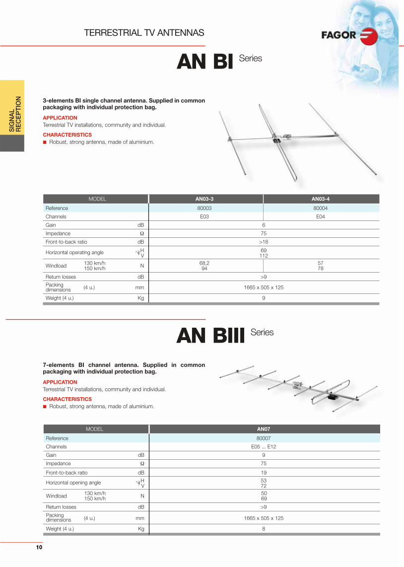
TERRESTRIAL TV ANTENNAS
3-elements BI single channel antenna. Supplied in commonpackaging with individual protection bag.
APPLICATIONTerrestrial TV installations, community and individual.
CHARACTERISTICS■ Robust, strong antenna, made of aluminium.
7-elements BI channel antenna. Supplied in commonpackaging with individual protection bag.
APPLICATIONTerrestrial TV installations, community and individual.
CHARACTERISTICS■ Robust, strong antenna, made of aluminium.
AN BI Series
MODEL AN03-3 AN03-4
Reference 80003 80004
Channels E03 E04
Gain dB 6
Impedance 75
Front-to-back ratio dB >18
H 69Horizontal operating angle o<) V 112
Windload 130 km/h N 68,2 57150 km/h 94 78
Return losses dB >9
Packingdimensions (4 u.) mm 1665 x 505 x 125
Weight (4 u.) Kg 9
AN BIII Series
MODEL AN07
Reference 80007
Channels E05 ... E12
Gain dB 9
Impedance 75
Front-to-back ratio dB 19
H 53Horizontal opening angle o<)V 72
Windload 130 km/h N 50150 km/h 69
Return losses dB >9
Packingdimensions (4 u.) mm 1665 x 505 x 125
Weight (4 u.) Kg 8
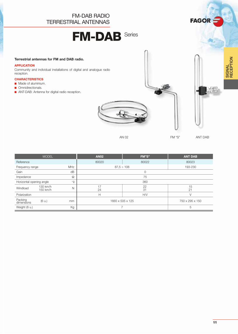
FM-DAB RADIOTERRESTRIAL ANTENNAS
Terrestrial antennas for FM and DAB radio.
APPLICATIONCommunity and individual installations of digital and analogue radioreception.
CHARACTERISTICS■ Made of aluminium.■ Omnidirectionals.■ ANT-DAB: Antenna for digital radio reception.
AN 02 FM “S” ANT DAB
11
SIG
NA
L R
EC
EP
TIO
N
FM-DAB Series
MODEL AN02 FM”S” ANT DAB
Reference 80020 80022 80023
Frequency range MHz 87,5 ÷ 108 193-230
Gain dB 0
Impedance 75
Horizontal opening angle o<) 360
Windload 130 km/h N 17 22 15150 km/h 24 31 21
Polarization H H/V V
Packingdimensions (6 u.) mm 1665 x 505 x 125 750 x 295 x 150
Weight (6 u.) Kg 7 5

UHF antennas for easy installation, obtaining importanttime economies and optimum electrical characteristics.They are designed to receive both vertical or horizontalpolarization signals. The wide range of models allows tocover a large variety of existing signals.
APPLICATIONAnalogue and Digital Terrestrial TV Installations, both individual orcommunity.
CHARACTERISTICS■ Quick and easy antenna mounting since ergonomical wing nuts are
provided.■ Tool-less set up of the reflectors.■ A built-in broadband symmetrizer guarantees life-long performance
of the antenna.
TERRESTRIAL TV ANTENNAS UHF
HORIZONTAL OPENING DIAGRAM
FAN 13 FAN 23
FAN 43 FAN 103
90° 90°
60°60°
30° 30°0 dB
-10
-20
90° 90°
60°60°
30° 30°0 dB
-10
-20
90° 90°
60°60°
30° 30°0 dB
-10
-20
90° 90°
60°60°
30° 30°0 dB
-10
-20
FAN 10369FAN 10351FAN 10337
FAN 4369FAN 4351FAN 4337
GAIN RESPONSE
dB 13
12
11
10
9
8
dB 15
14
13
12
11
10
9
dB 17
16
15
14
13
12
11
10
21 25 30 35 40 45 50 55 60 65 69
21 25 30 35 40 45 50 55 60 65 69
21 25 30 35 40 45 50 55 60 65 69
FAN 2369
12
SIG
NA
L R
EC
EP
TIO
N
FAN Series
MODEL FAN 1369 FAN 2369 FAN 4337 FAN 4351 FAN 4369 FAN 10337 FAN 10351 FAN 10369
Reference 81369 82369 84337 84351 84369 80337 80351 80369
Channels 21 ... 69 21 ... 69 21 ... 37 21 ... 51 21 ... 69 21 ... 37 21 ... 51 21 ... 69
Gain dB 10,5 12,5 14,5 16,5
Impedance 75
Return losses dB 9
Front-to-back ratio dB 25
Horizontal opening angle º<) 54 40 33 22
Windload 130 km/h N 50 54 70 112150 km/h 69 74 97 154
Length mm 474 818 1.267 1.232 1.253 2.442 2.390 2.490
Units per package 6 4 5 6 3
Packing dimensions mm 1300 x 505 x 165 1300 x 505 x 255 1300 x 505 x 255
Weight Kg 10 8 9 11 9

Rhombus shape antenna that provides a superior responsein the UHF band.
APPLICATIONSpecifically designed for Digital and Analogue Terrestrial TV installations.
CHARACTERISTICS■ Pre-assembled for easy set-up.■ The reflector and dipole have been designed for a higher front-to
back ratio.■ Long-life antenna due to its aluminium and “luran” plastic
construction.■ Ergonomic design for a tool-free installation.■ Suitable for horizontally or vertically polarised channels, maintaining
its water-resistance in any position.■ It has an “F” connector with protection cover.■ In case of low coverage areas, it allows to incorporate the @ktive,
a dipole that improves the antenna factor of merit in the installation(included in ref. 84386 and 84387).
DIGITAL TERRESTRIAL TV ANTENNAUHF
GAIN RESPONSE HORIZONTAL OPENING DIAGRAM
90° 90°
60°60°
30° 30°0 dB
-10
-20
21 25 29 33 37 41 45 49 53 57 61 65 69
dB 33.032.031.030.029.028.027.026.025.024.023.022.021.020.019.018.017.016.015.014.013.012.011.0
Di@na G69 16,5 dB
Di@na G69 @ktive 32 dB
13
SIG
NA
L R
EC
EP
TIO
N
Supply voltage 12 ÷ 24 Vdc
Current drawn 25 mA
SeriesDi@na G 69
MODEL Di@na G69 Di@na G69 6U Di@na G69 @ktive Di@na G69 @ktive 6U
Reference 84375 84377 84387 84386
Channels 21 ... 69
Gain dB 16,5 32
Impedance 75
Return losses dB 15
Front-to-back ratio dB 25
Horizontal opening angle º<) 33
Length mm 1.126
Windload 130 km/h N 71150 km/h 98
Units per package 1 1 (6u. Diana G69) 1 1 (6u. Diana G69 @ktive)
Packing Dimensions mm 740 x 330 x 180 760 x 340 x 650 740 x 330 x 180 760 x 340 x 650
Weight Kg 2 12 2 12

@ktive
LOW NOISE, ACTIVE DIPOLE
DESCRIPTIONUHF Preamplifier designed for TV reception in weak signal areas.
CHARACTERISTICS■ Low noise figure■ Protected against electric discharge■ High output level■ Designed with SMD technology■ Embedded shielding by design■ Excellent adaptation to input and output impedance■ Especially designed for Di@na antenna
MOUNTING OF @ktive ON DI@NA ANTENNA
SIG
NA
L R
EC
EP
TIO
N
14
MODEL @ktive
Reference 84385
Band covered MHz 470 ÷ 862
Minimum input level for S/N = 30 dB, analogue TV dBμV 34
Minimum input level for S/N = 19 dB, digital TV dBμV 23,5
Input impedance 300
Maximum output level DIN 45004B (-60 dB) dBμV 102
Output impedance 75
Output connector F(f)
Gain dB 18 (470 MHz) / 15 (862 MHz)
Noise figure dB 2
Packing dimensions mm 424 x 200 x 92
Weight Kg 0,250
Supply voltage 12 ÷ 24 Vdc
Current drawn 25 mA
Operating temperature range –20 ÷ 60º C
220 VAC
TV
HI-FI
AMB 836
FA 802N
DAB FM
Level meterTEST
(-30 dB)
24 VDC
Di@na G69 + @ktive

15
SIG
NA
L R
EC
EP
TIO
NCompact UHF antenna. Supplied in common packagingwith individual protection bag.
APPLICATIONSuitable for signal reception in individual and community installations.
CHARACTERISTICS■ Easy to assemble, just a click to put the directors and dipole into
place.■ The reflector and dipole have been designed for a higher Front-to-
back ratio.■ Suitable for horizontally or vertically polarised channels, maintaining
its water resistant feature.
DIGITAL TERRESTRIAL TV ANTENNAUHF
GAIN RESPONSE HORIZONTAL OPENING DIAGRAM
dB 13
12
11
10
9
821 25 30 35 40 45 50 55 60 65 69
90° 90°
60°60°
30° 30°0 dB
-10
-20
Min@ Series
MODEL Min@
Reference 84372
Channels 21 ... 69
Gain dB 12,5
Impedance 75
Return losses dB 15
Front-to-back ratio dB 25
Horizontal opening angle º<) 40
Length mm 750
Windload 130 km/h N 54150 km/h 74
Units per package 10
Packing dimensions (10 u.) mm 770 x 220 x 700
Weight (10 u.) Kg 14,5
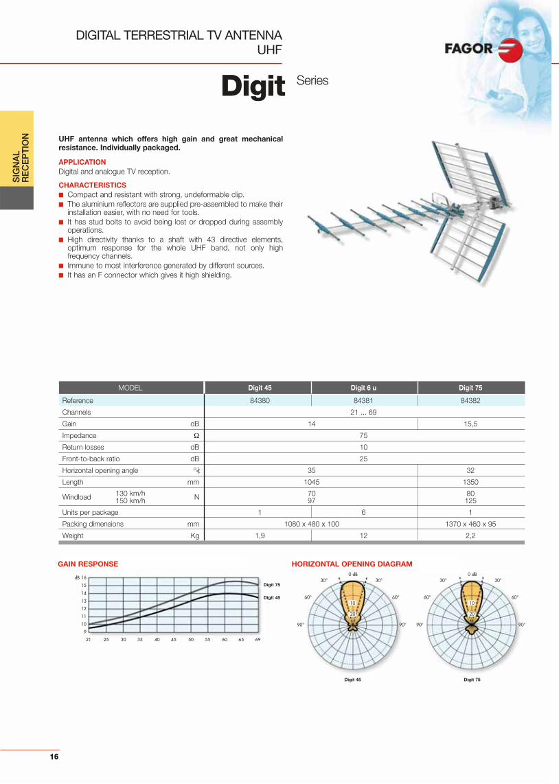
UHF antenna which offers high gain and great mechanicalresistance. Individually packaged.
APPLICATIONDigital and analogue TV reception.
CHARACTERISTICS■ Compact and resistant with strong, undeformable clip.■ The aluminium reflectors are supplied pre-assembled to make their
installation easier, with no need for tools. ■ It has stud bolts to avoid being lost or dropped during assembly
operations.■ High directivity thanks to a shaft with 43 directive elements,
optimum response for the whole UHF band, not only highfrequency channels.
■ Immune to most interference generated by different sources.■ It has an F connector which gives it high shielding.
DIGITAL TERRESTRIAL TV ANTENNAUHF
Digit
GAIN RESPONSE
dB 16
15
14
13
12
11
10
9
21 25 30 35 40 45 50 55 60 65 69
HORIZONTAL OPENING DIAGRAM
MODEL Digit 45 Digit 6 u Digit 75
Reference 84380 84381 84382
Channels 21 ... 69
Gain dB 14 15,5
Impedance 75
Return losses dB 10
Front-to-back ratio dB 25
Horizontal opening angle º<) 35 32
Length mm 1045 1350
Windload 130 km/h N 70 80150 km/h 97 125
Units per package 1 6 1
Packing dimensions mm 1080 x 480 x 100 1370 x 460 x 95
Weight Kg 1,9 12 2,2
16
SIG
NA
L R
EC
EP
TIO
N
90° 90°
60°60°
30° 30°0 dB
-10
-20
90° 90°
60°60°
30° 30°0 dB
-10
-20
Digit 75
Digit 45 Digit 75
Digit 45
Series

SATELLITE
Satellite dishes manufactured in electro zinc-coated steelwith a polyester coating ensuring high level of resistance toweather conditions.
APPLICATIONSuitable for community and individual Satellite TV installations.Available a wide range of diameters according to the size of the ins-tallation.
CHARACTERISTICS■ The parabolic reflectors are designed to achieve high gain.■ Pole or wall mounting.
DISHES
17
SIG
NA
L R
EC
EP
TIO
N
MODEL PO 064 PO 081 DPO 105*
Reference 86064 86081 86105
Diameter cm 51 x 57 73 x 80 91 x 100
Focal distance cm 32,7 46,8 58,3
Type of reflector OffsetMaterial Electro zinc-coated steel
Coating Polyester
Type of fixing Floor / Wall / Pole Pole
Mast diameter mm 30 ÷ 60 30 ÷ 60 30 ÷ 60
Elevation º<) 17 ÷ 55 17 ÷ 55 – 5 ÷ 82
Offset angle º<) 19
Azimuth º<) 180
LNB fixing Ø mm 25 ÷ 40
Frequency range GHz 10 ÷ 12,75
Gain (11,7 Ghz) dB 35 38 39,2
Efficiency % >60
Beam width (– 3 dB) º<) 2,8 2,4 2,1F/D relation 0,64
Operating: up to 100 km/hWind speed Maximum: up to 130 km/h
Packing dimensions mm 610 x 610 x 110 830 x 840 x 120 1020 x 1000 x 120
Weight Kg 5 9 10
*Pole not included. See accessories
ANTENNES
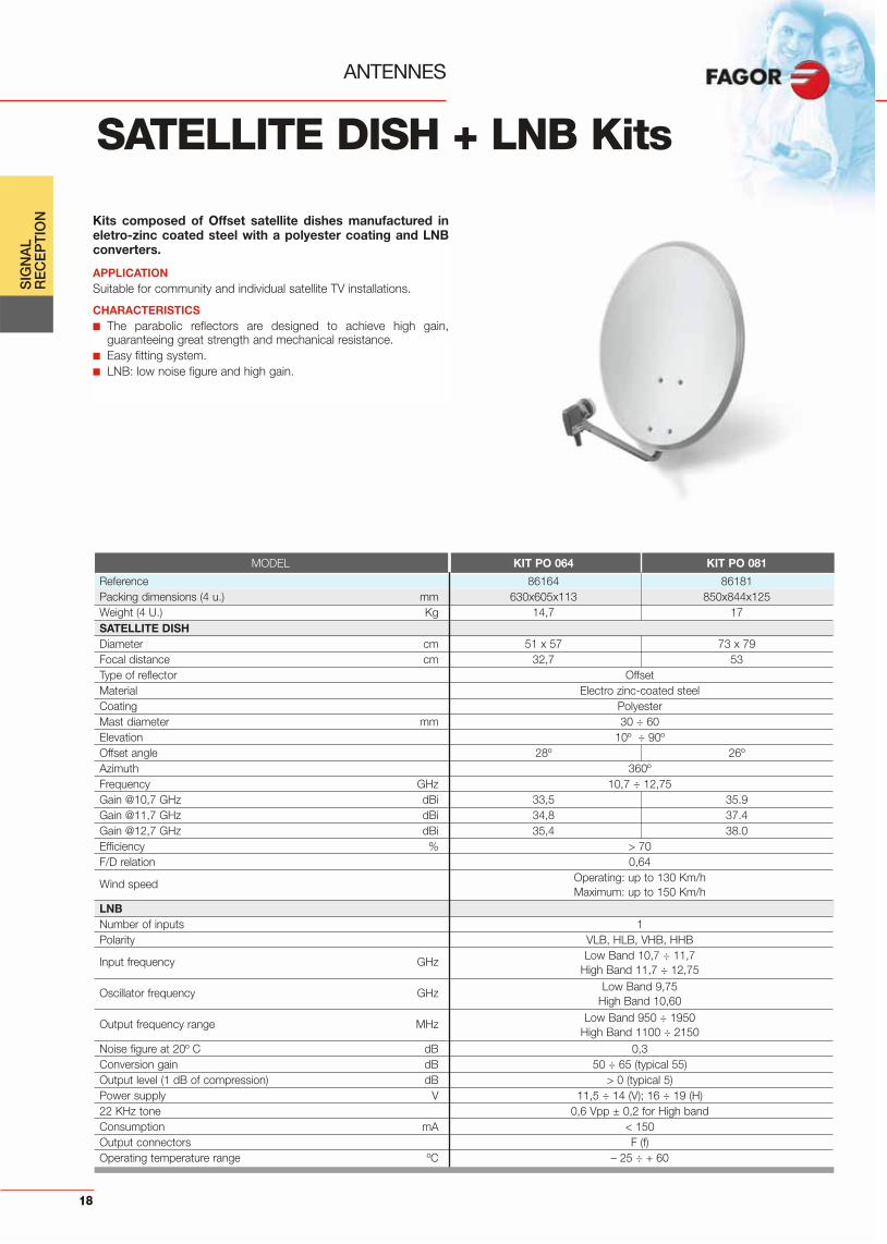
Kits composed of Offset satellite dishes manufactured ineletro-zinc coated steel with a polyester coating and LNBconverters.
APPLICATIONSuitable for community and individual satellite TV installations.
CHARACTERISTICS■ The parabolic reflectors are designed to achieve high gain,
guaranteeing great strength and mechanical resistance.■ Easy fitting system.■ LNB: low noise figure and high gain.
SATELLITE DISH + LNB Kits
SIG
NA
L R
EC
EP
TIO
N
18
MODEL KIT PO 064 KIT PO 081
Reference 86164 86181Packing dimensions (4 u.) mm 630x605x113 850x844x125Weight (4 U.) Kg 14,7 17SATELLITE DISHDiameter cm 51 x 57 73 x 79Focal distance cm 32,7 53Type of reflector OffsetMaterial Electro zinc-coated steelCoating PolyesterMast diameter mm 30 ÷ 60Elevation 10º ÷ 90ºOffset angle 28º 26ºAzimuth 360ºFrequency GHz 10,7 ÷ 12,75Gain @10,7 GHz dBi 33,5 35.9Gain @11,7 GHz dBi 34,8 37.4Gain @12,7 GHz dBi 35,4 38.0Efficiency % > 70F/D relation 0,64
Wind speed Operating: up to 130 Km/hMaximum: up to 150 Km/h
LNBNumber of inputs 1Polarity VLB, HLB, VHB, HHB
Input frequency GHz Low Band 10,7 ÷ 11,7High Band 11,7 ÷ 12,75
Oscillator frequency GHz Low Band 9,75 High Band 10,60
Output frequency range MHz Low Band 950 ÷ 1950High Band 1100 ÷ 2150
Noise figure at 20º C dB 0,3Conversion gain dB 50 ÷ 65 (typical 55)Output level (1 dB of compression) dB > 0 (typical 5)Power supply V 11,5 ÷ 14 (V); 16 ÷ 19 (H)22 KHz tone 0,6 Vpp ± 0,2 for High bandConsumption mA < 150Output connectors F (f)Operating temperature range ºC – 25 ÷ + 60

LNB
CONVERTERS
Universal low noise block converters suitable for any offsetsatellite dish.
APPLICATIONValid for any commercial TV SAT applications. The Universal modelhas one output for individual installations and the Quattro model has4 outputs for community installations.
CHARACTERISTICS■ Stand out for their low noise figure and high gain which together
with Offset type satellite dishes make it possible to obtain meritfactors ideal for collective installations.
■ One model for any kind of Ku transmission band.
SIG
NA
L R
EC
EP
TIO
N
19
Series
MODEL LNB 201 Universal LNB 204 Quattro
Reference 86129 86131
Number of inputs 1 4
Polarity VLB, HLB, VHB, HHB VLB HLB VHB HHB
Low band 10,7 ÷ 11,7Input frequency GHzHigh band 11,7 ÷ 12,75
Low band 9,75 ± 2 MHzOscillator frequency GHzHigh band 10,60 ± 2 MHz
Low band 950 ÷ 1950Output frequency range MHzHigh band 1100 ÷ 2150
Noise figure at 20º C dB 0,9
Conversion gain dB 50 ÷ 65 (typical 58)
Output level (1 dB of compression) dBm >0
Power supply V 11,5 ÷ 14 (V); 16 ÷ 19 (H) 11,5 ÷ 19
22 KHz tone 0,6 Vpp ± 0,2 for High band —
Consumption mA <200 <300
Output connectors F (f)
Operating temperature range ºC – 25 ÷ + 60
Packing dimensions mm 150 x 113 x 75
Weight Kg 0,48

1st IF SAT LINE AMPLIFIER
AL 461st IF SAT signal line amplifier.
APPLICATIONSuitable for digital or analogue TV installations.
CHARACTERISTICS■ Offers a linear response, up to 2150 MHz.■ Transparent for 22 KHz switching signal control.■ Remote powered through the coaxial cable.
FM
AMB820
FA 802 N
BSD 203 DC
AL-46
PO 064
Receptor SAT
Receptor TDT
INRF
DXR 216
INSAT
LNB 201 TVTV
HI FI
UHF
Individual installation application example
20
SIG
NA
L R
EC
EP
TIO
N
MODEL AL 46
Reference 86246
Type of connector F (f)
Frequency range MHz 950 ÷ 2300
Gain (950 ÷ 2300 MHz) dB 15 ÷ 18
Noise figure dB 7
Max. output level (- 35 dB) dBμV 109
Current drawn mA 50
DC pass (max.) A 1
Supply voltage Vdc 15 ± 3
Packing dimensions mm 80 x 20 x 25
Weight Kg 0,1
MECHANICAL ACCESSORIES
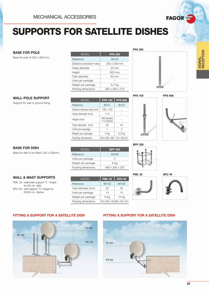
SUPPORTS FOR SATELLITE DISHES
BASE FOR DISHBase for dish to be fitted. 200 x 200mm.
MODEL BPP 200
Reference 82436
Units per package 2
Weight per package 6 Kg
Packing dimensions 480 x 290 x 320
BASE FOR POLEBase for pole of 200 x 200 mm.
MODEL PPA 200
Reference 86104
Distance between holes 200 x 200 mm
Holes diameter 20 mm
Height 820 mm
Tube diameter 60 mm
Units per package 1
Weight per package 6,7 Kg
Packing dimensions 920 x 280 x 270
WALL-POLE SUPPORTSupport for wall or ground fixing.
MODEL PPS 100 PPS 806
Reference 86101 86102
Distance between holes (mm) 190 x 100 –
Holes diameter (mm) 11,5 –
Height (mm) 468 (straight) –713 (vertical)
Tube diameter (mm) 50 40
Units per package 1 2
Weight per package 4 Kg 3,3 Kg
Packing dimensions 525 x 280 x 260 720 x 235x 50
WALL & MAST SUPPORTSPML 32: wall/mast support "L" shape
for 65 cm. dish.SPU 40: wall support "U" shape for
65/80 cm. dishes.
MODEL PML 32 SPU 40
Reference 86103 86106
Tube diameter (mm) 32 40
Units per package 10 10
Weight per package 8 Kg 15 Kg
Packing dimensions 440 x 380 x 130 580 x 430 x 210
FITTING A SUPPORT FOR A SATELLITE DISH
PPA 200
PO 064
PPS 100
FITTING A SUPPORT FOR A SATELLITE DISH
PO 064
PPS 806
SIG
NA
L R
EC
EP
TIO
N
21
PPA 200
PPS 100 PPS 806
BPP 200
PML 32 SPU 40

SIG
NA
L R
EC
EP
TIO
N
22
MECHANICAL ACCESSORIES
Triangular shaped towers made of several sections and atop part to fix an antenna mast.
APPLICATIONInstallations in which the antennas have to be located at a great heightor where the strength of the antennas needs reinforcing.
CHARACTERISTICS■ Made of zinc-plated iron.■ Round tube diameter: 20 mm.■ The towers can be fixed to the ground or roof by means of a tower
base that can be screwed or embedded.
PNT 15 PNT 25 TRT 25
TOWERS
PUTTING UP A TOWER
PNT 15PNT 25TRT 25
APR 035
CBL AC3
TNS 106 BTR ATBTR EMBTR AB
ANC VT
MODEL PNT 15 PNT 25 TRT 25
Reference 82401 82402 82403
Tower type upper upper lower
Height mm 1500 2500 2500
Width mm 180
Max. mast diameter mm 46
Material Zinc-plated iron
Units per package 1
Packing weight Kg 5 8 7
Packing dimensions mm 1500 x 180 x 180 2700 x 180 x 180 2500 x 180 x 180

23
SIG
NA
L R
EC
EP
TIO
N
MECHANICAL ACCESSORIES
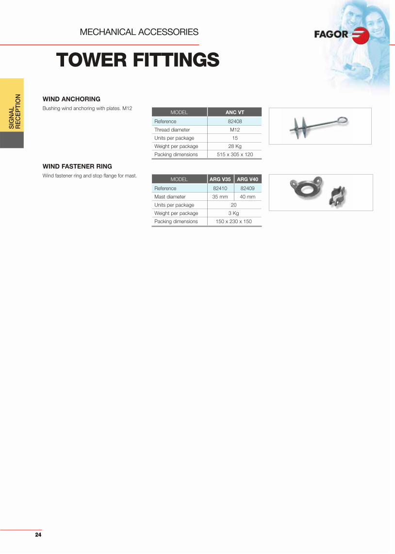
TOWER FITTINGS
MODEL BTR AT
Reference 82405
Width 180 mm
Units per package 4
Weight per package 6 Kg
Packing dimensions 310 x 310 x 220
TOWER BASE FOR SCREWING
TOWER BASE FOR EMBEDDING
GUY WIRE
Base for screwing zinc-plated iron tower.
Base for screwing zinc-plated iron tower.
3 mm braided steel wire.
MODEL BTR EM
Reference 82406
Width 180 mm
Units per package 4
Weight per package 8 Kg
Packing dimensions 510 x 310 x 220
PIVOTING TOWER FOR EMBEDDING
MODEL BTR AB
Reference 82407
Width 180 mm
Units per package 4
Weight per package 8 Kg
Packing dimensions 510 x 310 x 220
MODEL CBL AC3
Reference 82411
Length 100 m.
Weight per package 1,5 Kg
Packing dimensions 190 x 190 x 60
WIND TENSIONING DEVICE1/4“ tensioning device for wind. M8
MODEL TNS 106
Reference 82427
Units per package 25
Packing weight 1 Kg
Packing dimensions 150 x 25 x 20
24
TOWER FITTINGS
MECHANICAL ACCESSORIES
SIG
NA
L R
EC
EP
TIO
N WIND ANCHORINGBushing wind anchoring with plates. M12
MODEL ANC VT
Reference 82408
Thread diameter M12
Units per package 15
Weight per package 28 Kg
Packing dimensions 515 x 305 x 120
MODEL ARG V35 ARG V40
Reference 82410 82409
Mast diameter 35 mm 40 mm
Units per package 20
Weight per package 3 Kg
Packing dimensions 150 x 230 x 150
WIND FASTENER RINGWind fastener ring and stop flange for mast.
25
SIG
NA
L R
EC
EP
TIO
N
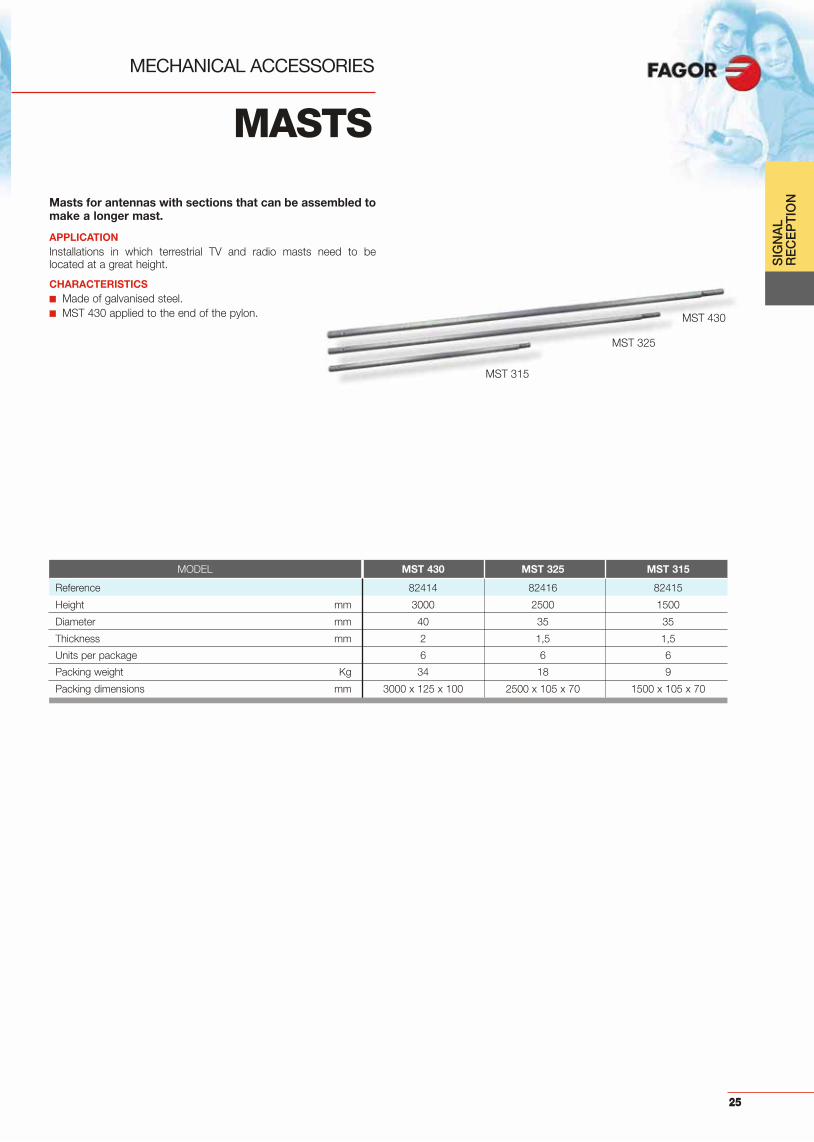
MASTS
MECHANICAL ACCESSORIES
Masts for antennas with sections that can be assembled tomake a longer mast.
APPLICATIONInstallations in which terrestrial TV and radio masts need to belocated at a great height.
CHARACTERISTICS■ Made of galvanised steel.■ MST 430 applied to the end of the pylon. MST 430
MST 325
MST 315
MODEL MST 430 MST 325 MST 315
Reference 82414 82416 82415
Height mm 3000 2500 1500
Diameter mm 40 35 35
Thickness mm 2 1,5 1,5
Units per package 6 6 6
Packing weight Kg 34 18 9
Packing dimensions mm 3000 x 125 x 100 2500 x 105 x 70 1500 x 105 x 70

SIG
NA
L R
EC
EP
TIO
N
26
MAST ACCESSORIES
MECHANICAL ACCESSORIES
MODEL BTJ 035
Reference 82418
Units per package 6
Packing weight 6 Kg
Packing dimensions 310 x 310 x 220
RIDGE TILE BASE FOR MAST
CHIMNEY BRACKET
Pivoting ridge tile base for 35-40 mm diameterand 41 mm inner diameter mast.
Bracket to fit a mast to a chimney, which bymeans of a wire and a tensioning deviceensures that a antenna mast is securely fixed.Enables masts to be fitted without any buildingwork on the facade.
MODEL ACH 045
Reference 82419
Mast diameter Up to 45 mm
Units per package 8
Weight 13 Kg
Dimensions 500 x 470 x 270
GUY WIRE TIGHTENERTightens 3 mm diameter guy wires.
MODEL APR 035
Reference 82429
Units per package 25
Packing weight 0,6 Kg
Dimensions 150 x 230 x 150
MODEL GRP 001
Reference 82428
Units per package 100
Packing weight 1,5 Kg
Packing dimensions 150 x 230 x 150
CLIPClip secured with nail.
SIG
NA
L R
EC
EP
TIO
N
27
CLAMPS
MECHANICAL ACCESSORIES
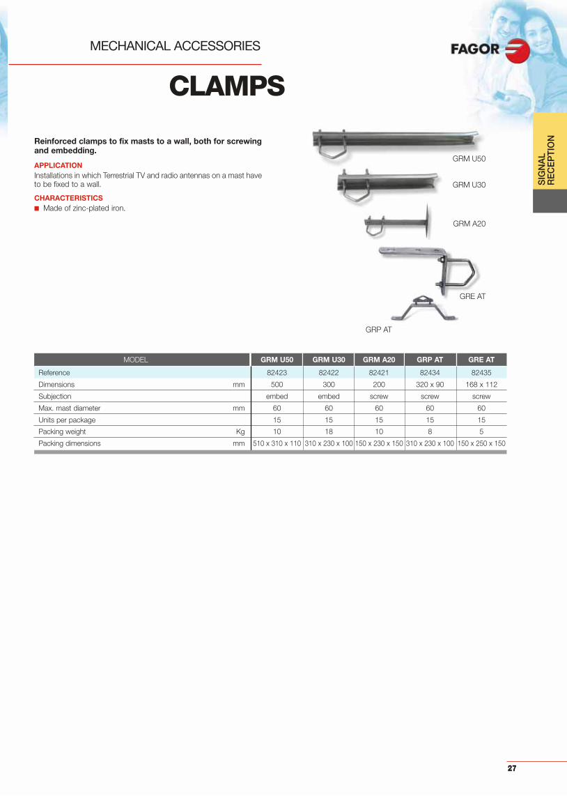
Reinforced clamps to fix masts to a wall, both for screwingand embedding.
APPLICATIONInstallations in which Terrestrial TV and radio antennas on a mast haveto be fixed to a wall.
CHARACTERISTICS■ Made of zinc-plated iron.
GRM U50
GRP AT
GRE AT
GRM U30
GRM A20
MODEL GRM U50 GRM U30 GRM A20 GRP AT GRE AT
Reference 82423 82422 82421 82434 82435
Dimensions mm 500 300 200 320 x 90 168 x 112
Subjection embed embed screw screw screw
Max. mast diameter mm 60 60 60 60 60
Units per package 15 15 15 15 15
Packing weight Kg 10 18 10 8 5
Packing dimensions mm 510 x 310 x 110 310 x 230 x 100 150 x 230 x 150 310 x 230 x 100 150 x 250 x 150

SIG
NA
L R
EC
EP
TIO
N
28
BRACKETS
MECHANICAL ACCESSORIES
DOUBLE BRACKET
SINGLE BRACKET
U-shaped zinc-plated bracket with three jawsfor fixing to the mast. For masts up to 60 mmin diameter. M8
U-shaped bracket with a jaw for fixing to themast.For masts up to 60 mm in diameter. M8
MODEL BRI D68
Reference 82425
Units per package 25
Packing weight 8 Kg
Packing dimensions 310 x 230 x 100
MODEL BRI S68
Reference 82426
Units per package 25
Packing weight 5 Kg
Packing dimensions 310 x 230 x 100
29
SIG
NA
L R
EC
EP
TIO
N
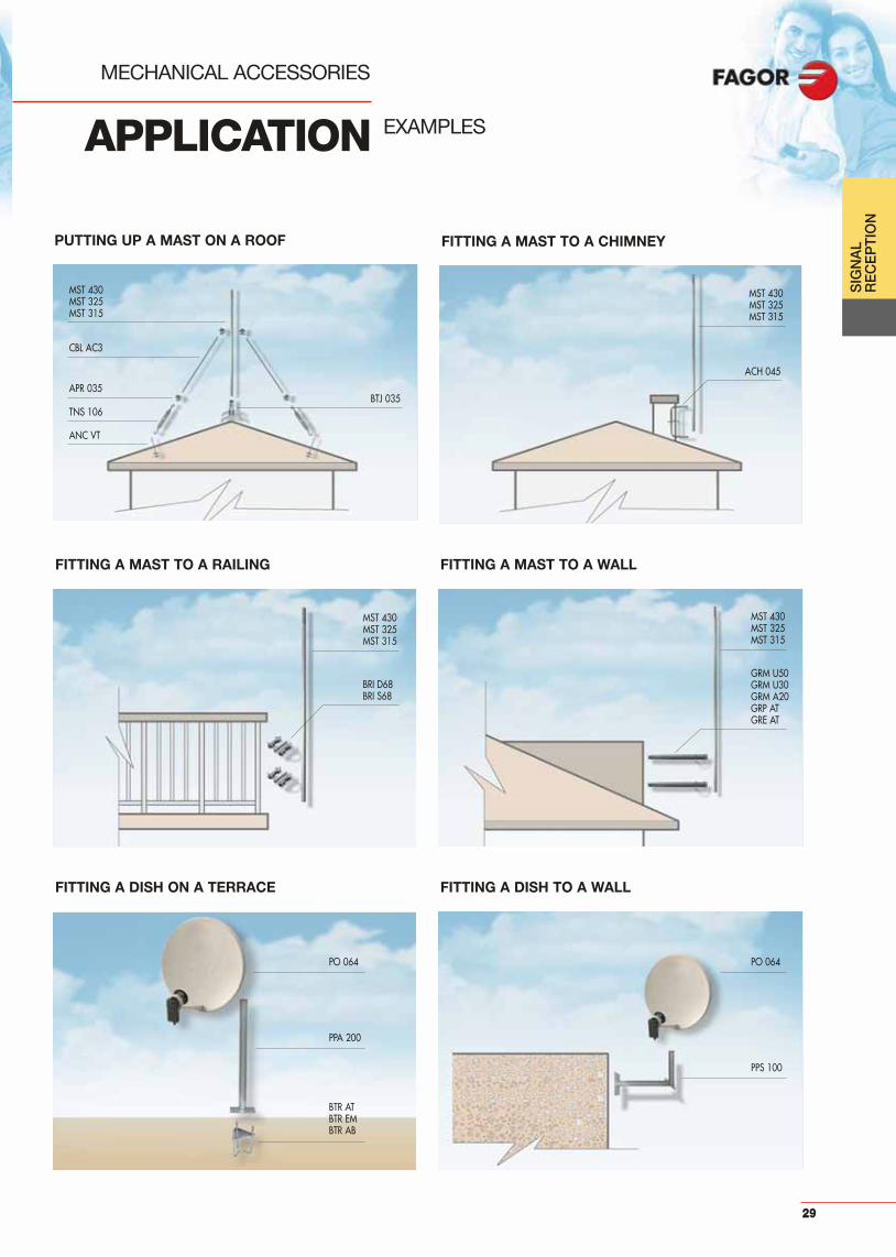
APPLICATION
MECHANICAL ACCESSORIES
EXAMPLES
FITTING A MAST TO A CHIMNEY
FITTING A MAST TO A WALLFITTING A MAST TO A RAILING
PUTTING UP A MAST ON A ROOF
CBL AC3
APR 035
TNS 106
MST 430MST 325MST 315
MST 430MST 325MST 315
BRI D68BRI S68
MST 430MST 325MST 315
GRM U50GRM U30GRM A20GRP ATGRE AT
FITTING A DISH TO A WALLFITTING A DISH ON A TERRACE
PO 064PO 064
PPA 200
BTR ATBTR EMBTR AB
PPS 100
ACH 045
BTJ 035
ANC VT
MST 430MST 325MST 315

30
31
HE
AD
EN
DS
ifferent systems based on the specific requi-rements of each installation. From systems
covering different types of processing under thesame format, like the Multi-Processing System,to universal amplification solutions like theMICROMATV® series.
MULTI-PROCESSING SYSTEM
• SRM+ Receiver - Modulator ................................. 32
• SRM+ ST Stereo Receiver - Modulator ................ 33
• SM+ VSB Modulator .............................................. 34
• SM+ ST Stereo VSB Modulator ............................ 35
• CIF + A/D Channel converter via IF ...................... 36
• SDT N QPSK/QAM Transmodulator...................... 37
• SDT SB QPSK/QAM Transmodulator ................... 38
• SDM+ QPSK/AM Demodulator-Modulator ................ 39
• SDM+ ST QPSK/AM Stereo Demodulator-Modulator ...... 40
• TDM COFDM - PAL Transmodulator..................... 41
• TDM-ST COFDM - PAL Stereo Transmodulator .. 42
• AFM FM Amplifier .................................................. 43
• SHA N/ SAC N Headend Amplifier ........................ 44
• IFL 1st IF SAT Twin Converter .............................. 45
• IFA S 1st IF SAT Headend Amplifier...................... 46
• SPS N Power supply............................................... 47
• SPS+ Power supply ................................................ 48
• Accessories............................................................. 49
• Application Examples............................................. 51
QPSK-AM COMPACT HEADEND• Disat 6 ..................................................................... 54
NEXUM SERIES
• NEX Channel Amplifier........................................... 55
• NEX Multi-channel Amplifier ................................. 56
• IFA 1st IF SAT Amplifier ......................................... 57
• SPS 523 Power supply ........................................... 58
• Accessories............................................................. 59
• Examples ................................................................. 61
MICROMATV SYSTEM
• MicroMATV FUTURA .............................................. 62
• UCF 200 - BUS adapter.......................................... 63
• MicroMATV plus ...................................................... 64
• MicroMATV plus N .................................................. 65
• MicroMATV .............................................................. 66
• SAB Series............................................................... 68
• Accessories............................................................. 69
• Examples ................................................................. 70
BAND AND DISTRIBUTION APLIFIERS & DTT RECEIVER
• SABAL Series .......................................................... 71
• DWBA 415................................................................ 72
• IFA 2000 N................................................................ 73
• TEDI 200 .................................................................. 74
• Examples ................................................................. 75
D INDEX Page
Headends

HE
AD
EN
DS
32
Analogue satellite TV receiver – modulator. Each modulereceives a Satellite TV channel and converts it into anAM-modulated RF channel. Just one model is all that isnecessary for any input or output channel.
APPLICATIONAnalogue satellite TV installations in large and medium sizecommunities. No need of individual receivers with each TV set.
CHARACTERISTICS■ Includes independent processing of audio carriers with PANDA-
compatible adaptive de-emphasis. ■ All system’s functions are memorised and controlled by a FAGOR
microprocessor.■ The direct connection between LNB and receiver and the possibility
of a splitting function at the input allows a very simple set-up.■ The modulator operates in any TV channel (BI, BIII, “S” Bands and
UHF) and its VSB output allows adjacent channel operation.■ The output auto-combining system and the signal of high spectral
purity allows broad band amplification.■ It also offers the possibility of fine tuning the output channel
frequency to disperse intermodulation products in installations withmany channels.
■ RF output signal ON/OFF switchable for analysis and headendadjustment.
■ Brightness adjustment available.■ Video modulation depth adjustable from 75 to 90%.■ Incorporates test bars generator.■ It allows to generate black screen for distributing audio signals.■ Screws and power supply cable included.
SRM 6000+ / SRM 7000+
MULTI - PROCESSING SYSTEMRECEIVER - MODULATOR
*Standards available: B/G, I, L, D/K, M, N…
MODEL * SRM 6000+ SRM 7000+
Reference 27660 27760
Assembly system Frame 19” Rack
Input/output connectors F (f)
1st IF input frequency MHz 950 ÷ 2150
Input level dBμV 49 ÷ 77 (–60 ÷ –32 dBm)
1st IF through losses dB 1,5
Dynamic threshold S / N dB < 8
B/G 18/27 (switchable)2nd IF bandwidth MHz L 27/36
AFC pulling range MHz ± 5
Audio tuning band MHz 4,3 ÷ 9mono: single subcarrier
Audio modes Stereo: double subcarrier ( 180 KHz)
IF audio bandwidth KHz 150 / 330 / PANDA compatible
Audio de-emphasis 50μs / J17 / PANDA adaptive (75μs)
Video de-emphasis CCIR (Curve B / RC 405.1)
VSB output channel E2... 69 (programmable)
Output level dBμV 75 ÷ 90 (adjustable)
Spurious in channel dBc – 60
Spurious in band dBc – 54
C/N ratio (8 modules) dB 56
Carrier accuracy KHz ± 30
Carrier stability KHz ± 10
Output fine tuning KHz ± 4,5 ( = 125 KHz)
Video modulation depth % 75...90
Packing dimensions mm 272 x 166 x 45
Weight Kg 1,7
Supply voltage Vdc 30 17 12 5
Current drawn (7,95 W) mA 3 16 460 415
Operating temperature range 0 ÷ 50º C
33
HE
AD
EN
DS
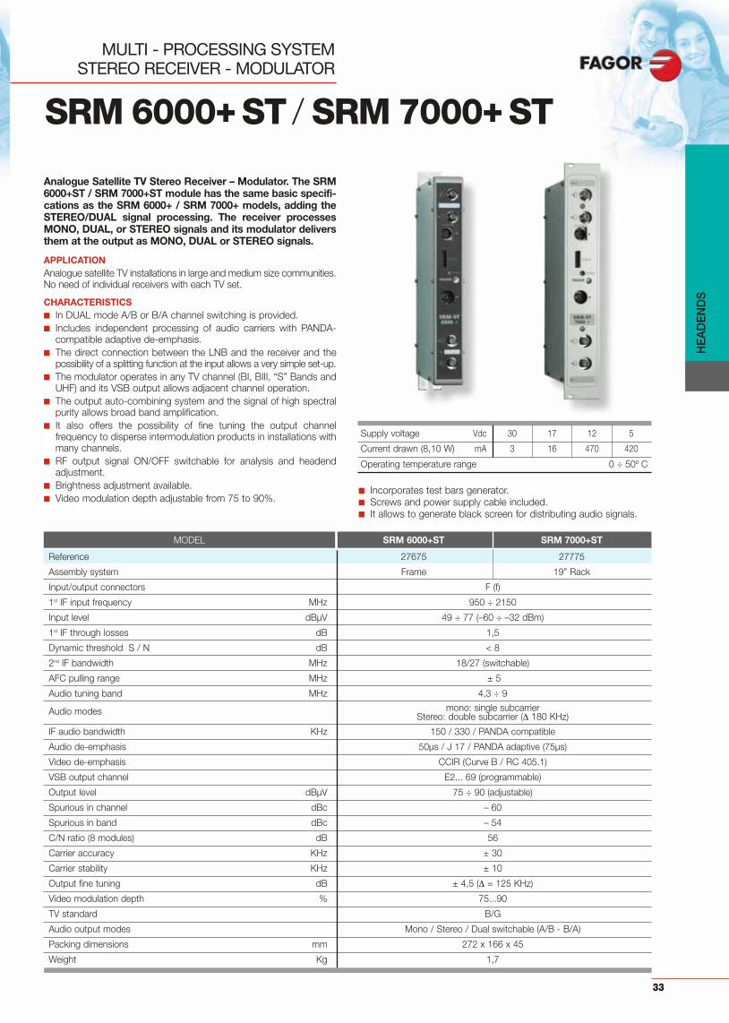
Analogue Satellite TV Stereo Receiver – Modulator. The SRM6000+ST / SRM 7000+ST module has the same basic specifi-cations as the SRM 6000+ / SRM 7000+ models, adding theSTEREO/DUAL signal processing. The receiver processesMONO, DUAL, or STEREO signals and its modulator deliversthem at the output as MONO, DUAL or STEREO signals.
APPLICATIONAnalogue satellite TV installations in large and medium size communities.No need of individual receivers with each TV set.
CHARACTERISTICS■ In DUAL mode A/B or B/A channel switching is provided.■ Includes independent processing of audio carriers with PANDA-
compatible adaptive de-emphasis.■ The direct connection between the LNB and the receiver and the
possibility of a splitting function at the input allows a very simple set-up.■ The modulator operates in any TV channel (BI, BIII, “S” Bands and
UHF) and its VSB output allows adjacent channel operation.■ The output auto-combining system and the signal of high spectral
purity allows broad band amplification.■ It also offers the possibility of fine tuning the output channel
frequency to disperse intermodulation products in installations withmany channels.
■ RF output signal ON/OFF switchable for analysis and headendadjustment.
■ Brightness adjustment available.■ Video modulation depth adjustable from 75 to 90%.
SRM 6000+ST / SRM 7000+ST
MULTI - PROCESSING SYSTEMSTEREO RECEIVER - MODULATOR
MODEL SRM 6000+ST SRM 7000+ST
Reference 27675 27775
Assembly system Frame 19” Rack
Input/output connectors F (f)
1st IF input frequency MHz 950 ÷ 2150
Input level dBμV 49 ÷ 77 (–60 ÷ –32 dBm)
1st IF through losses dB 1,5
Dynamic threshold S / N dB < 8
2nd IF bandwidth MHz 18/27 (switchable)
AFC pulling range MHz ± 5
Audio tuning band MHz 4,3 ÷ 9
Audio modes mono: single subcarrierStereo: double subcarrier ( 180 KHz)
IF audio bandwidth KHz 150 / 330 / PANDA compatible
Audio de-emphasis 50μs / J 17 / PANDA adaptive (75μs)
Video de-emphasis CCIR (Curve B / RC 405.1)
VSB output channel E2... 69 (programmable)
Output level dBμV 75 ÷ 90 (adjustable)
Spurious in channel dBc – 60
Spurious in band dBc – 54
C/N ratio (8 modules) dB 56
Carrier accuracy KHz ± 30
Carrier stability KHz ± 10
Output fine tuning dB ± 4,5 ( = 125 KHz)
Video modulation depth % 75...90
TV standard B/G
Audio output modes Mono / Stereo / Dual switchable (A/B - B/A)
Packing dimensions mm 272 x 166 x 45
Weight Kg 1,7
■ Incorporates test bars generator.■ Screws and power supply cable included. ■ It allows to generate black screen for distributing audio signals.
Supply voltage Vdc 30 17 12 5
Current drawn (8,10 W) mA 3 16 470 420
Operating temperature range 0 ÷ 50º C

HE
AD
EN
DS
34
Modulator with VSB output, that allows adjacent channeloperation. A programmable output channel means that themodulator can easily be inserted into the headend since itoperates in any TV channel (BI, BIII, “S” Bands and UHF).
APPLICATIONAnalogue satellite TV community installations, where locally producedchannels insertion is needed.
CHARACTERISTICS■ It allows audio volume adjustment to equalise them to the level of
other installed programs.■ It also offers the possibility of fine tuning the output channel
frequency to disperse intermodulation products in installations withmany channels.
■ RF output signal ON/OFF switchable for analysis and headendadjustment.
■ Brightness adjustment available..■ Video modulation depth adjustable from 75 to 90%.■ Incorporates test bars generator.■ Output frequency shift.■ Screws and power supply cable included.
SM 6000+ / SM 7000+
MULTI - PROCESSING SYSTEMVSB MODULATOR
*Standards available: B/G, I, L, D/K, M, N…
MODEL * SM 6000+ SM 7000+
Reference 19650 19750
Assembly system Frame 19” Rack
Input/output connector F (f)
Audio/Video input connector MINI DIN 5 ways (f)
Audio pre-emphasis μs 50
Video input level Vpp 0,9 ÷ 1,25 / 75
Audio input level Vpp 0,5 ÷ 2,5 ( = 13 KHz) / 10 K @ 1KHz
VSB output channel MHz E2... 69 (programmable)
Output level dBμV 75 ÷ 90 (adjustable)
Spurious in channel dBc – 60
Spurious in band dBc > 54
C/N ratio (8 modules) dB 56
Carrier accuracy KHz ± 30
Carrier stability KHz ± 10
Output fine tuning MHz ± 4,5 ( = 125 KHz)
Video modulation depth (switchable) % 85 + 5, –10 ( = 5%)
Pv / Ps ratio adjustable dB 13 + 1, –2 ( = 1 dB)
Packing dimensions mm 272 x 166 x 45
Weight Kg 1,5
Supply voltage Vdc 30 24 12 5
Current drawn (6,2 W) mA 1 70 320 133
Operating temperature range 0 ÷ 50º C

HE
AD
EN
DS
35
Modulator with VSB output, that allows adjacent channeloperation. It has 2 audio carriers for processing STEREO orDUAL signals. A programmable output channel means thatthe modulator can easily be inserted into the headend sinceit operates in any TV channel (BI, BIII, “S” Bands and UHF).
APPLICATIONAnalogue satellite TV community installations, where locally producedchannels insertion is needed.
CHARACTERISTICS■ In DUAL mode A/B or B/A channel switching is provided.■ It allows audio volume adjustment to equalise them to the level of
other installed programs.■ It also offers the possibility of fine tuning the output channel
frequency to disperse intermodulation products in installations withmany channels.
■ RF output signal ON/OFF switchable for analysis and headendadjustment.
■ Brightness adjustment available.■ Video modulation depth adjustable from 75 to 90%.■ Incorporates test bars generator ■ It allows to generate black screen for distributing audio signals.■ Screws and power supply cable included.
SM 6000+ST / SM7000+ST
MULTI - PROCESSING SYSTEMVSB STEREO MODULATOR
MODEL SM 6000+ST SM 7000+ST
Reference 19665 19765
Assembly system Frame 19” Rack
Input/output connector F (f)
Audio/Video input connector MINI DIN 5 ways (f)
Audio pre-emphasis μs 50
Video input level Vpp 0,9 ÷ 1,25 / 75
Audio input level Vpp 0,8 ÷ 1,1 ( = 13 KHz) / 10K
VSB output channel MHz E2... 69 (programmable)
Output level dBμV 75 ÷ 90 (adjustable)
Spurious in channel dBc – 60
Spurious in band dBc – 54
C/N ratio (8 modules) dB 56
Carrier accuracy KHz ± 30
Carrier stability KHz ± 10
Output fine tuning MHz ± 4,5 ( = 125 KHz)
Video modulation depth (switchable) % 85 + 5, –10 ( = 5%)
Pv / Ps ratio adjustable dB 13 + 1, –2 ( = 1 dB)
TV standard B / G
Audio output modes STEREO / DUAL switchable (A/B - B/A)
Packing dimensions mm 272 x 166 x 45
Weight Kg 1,5
Supply voltage Vdc 30 24 12 5
Current drawn (7,5 W) mA 1 115 335 145
Operating temperature range 0 ÷ 50º C
HE
AD
EN
DS
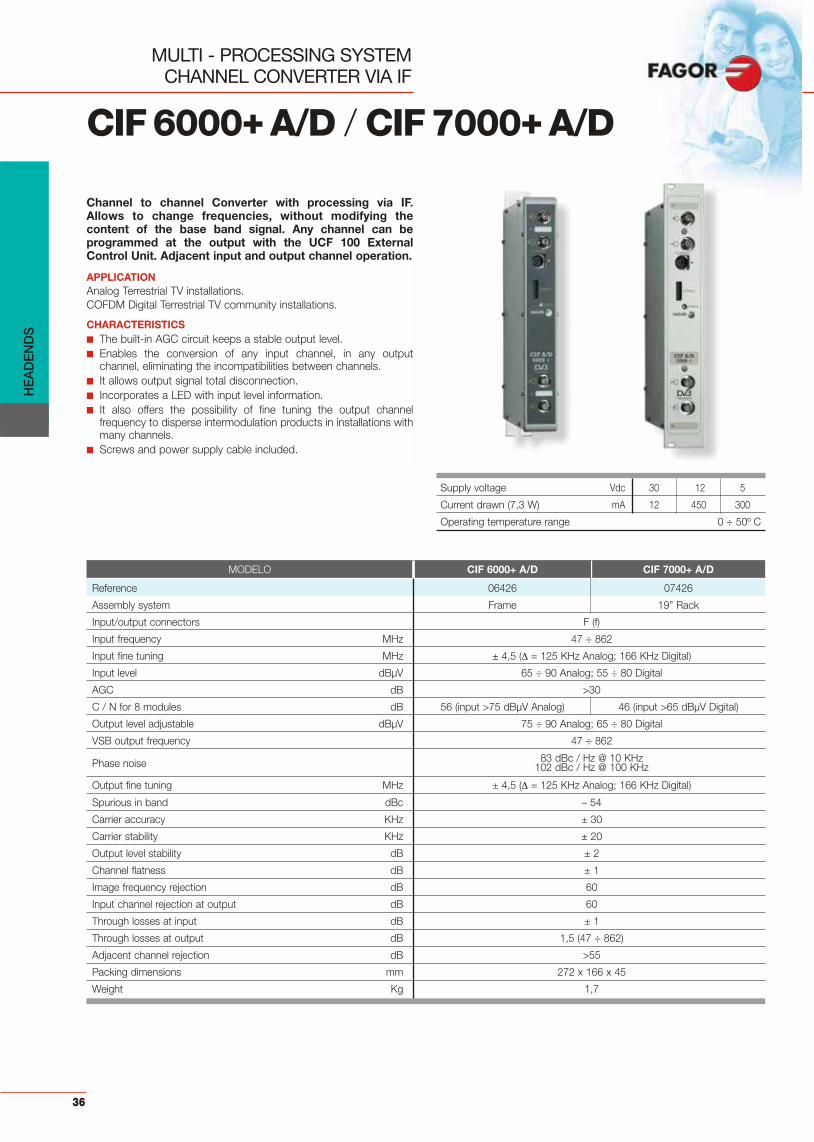
Channel to channel Converter with processing via IF.Allows to change frequencies, without modifying thecontent of the base band signal. Any channel can beprogrammed at the output with the UCF 100 ExternalControl Unit. Adjacent input and output channel operation.
APPLICATIONAnalog Terrestrial TV installations.COFDM Digital Terrestrial TV community installations.
CHARACTERISTICS■ The built-in AGC circuit keeps a stable output level.■ Enables the conversion of any input channel, in any output
channel, eliminating the incompatibilities between channels.■ It allows output signal total disconnection.■ Incorporates a LED with input level information.■ It also offers the possibility of fine tuning the output channel
frequency to disperse intermodulation products in installations withmany channels.
■ Screws and power supply cable included.
CIF6000+A/D / CIF7000+A/D
MULTI - PROCESSING SYSTEMCHANNEL CONVERTER VIA IF
MODELO CIF 6000+ A/D CIF 7000+ A/D
Reference 06426 07426
Assembly system Frame 19” Rack
Input/output connectors F (f)
Input frequency MHz 47 ÷ 862
Input fine tuning MHz ± 4,5 ( = 125 KHz Analog; 166 KHz Digital)
Input level dBμV 65 ÷ 90 Analog; 55 ÷ 80 Digital
AGC dB >30
C / N for 8 modules dB 56 (input >75 dBμV Analog) 46 (input >65 dBμV Digital)
Output level adjustable dBμV 75 ÷ 90 Analog; 65 ÷ 80 Digital
VSB output frequency 47 ÷ 862
Phase noise 83 dBc / Hz @ 10 KHz 102 dBc / Hz @ 100 KHz
Output fine tuning MHz ± 4,5 ( = 125 KHz Analog; 166 KHz Digital)
Spurious in band dBc – 54
Carrier accuracy KHz ± 30
Carrier stability KHz ± 20
Output level stability dB ± 2
Channel flatness dB ± 1
Image frequency rejection dB 60
Input channel rejection at output dB 60
Through losses at input dB ± 1
Through losses at output dB 1,5 (47 ÷ 862)
Adjacent channel rejection dB >55
Packing dimensions mm 272 x 166 x 45
Weight Kg 1,7
Supply voltage Vdc 30 12 5
Current drawn (7,3 W) mA 12 450 300
Operating temperature range 0 ÷ 50º C
36

HE
AD
EN
DS
37
SDT 6000N / SDT7000N
MULTI - PROCESSING SYSTEMQPSK / QAM TRANSMODULATOR
Transparent digital transmodulator that converts the QPSKsignal coming from the satellite into channels with QAM16/32/64/128/256 modulation for its distribution togetherwith the rest of the terrestrial and analogue satellitechannels through just one cable.
APPLICATIONVHF/UHF distribution SMATV installations, new or existing, equippedwith an extraordinary digital satellite-transmitted TV programmecapacity.
CHARACTERISTICS■ Adjacent channel operation.■ No need of input splitters or output combiners■ Displays BER, Bit Error Rate, for accurate measuring of installation
margin. ■ Easy programming of the output channel by UCF 100 Control Unit.■ Screws and power supply cable included.
MODEL SDT 6300 N SDT 7300 N SDT 6400 N SDT 7400 N
Reference 08136 08137 08146 08147
Assembly system Frame Rack 19” Frame Rack 19”
Input / output connectors F (f)
Input frequency MHz 950 ÷ 2150 (Resolution 1 MHz)
LNB powering V 18
Modulation type QPSK (DVB compatible)
Input level dBμV 44 ÷ 84 dBμV (– 65 ÷ – 25 dBm)
Input through losses dB 1,5
AFT pulling range MHz ± 5
IF band zero FI
QPSK Baud Rate Mbaud 1,5 ÷ 45 (Resolution 1K Baud)
Code rate (automatic) 1/2, 2/3, 3/4, 5/6, 7/8
FEC (Reed Solomon) DVB compliance
Deinterleaving DVB compliance
Descrambling DVB compliance
QAM modulation type 16/32/64/128/256 QAM
FEC (Reed Solomon) DVB compliance
Scrambling DVB compliance
Interleaving DVB compliance
Base band shaping (Roll-off) DVB compliance (12, 15, 18%)
Spectrum Inversion programmable
QAM Baud Rate Mbaud 7
MER dB > 35
Output frequency range MHz 47 ÷ 310 (Resolution 125 KHz) 302 ÷ 862 (Resolution 125 KHz)
Output through losses dB 1,5
Output level dBμV 65 ÷ 85 dBμV (– 44 ÷ – 24 dBm)
C/N ratio dB 46 typical
Output spurious dB < – 54 typical
Phase noise dB/Hz – 85 dBc @ 10 KHz
Packing dimensions mm 272 x 166 x 45
Weight Kg 1,6
Supply voltage Vdc 30 17 12 5
Current drawn (8,5 W) mA 1 15 330 770
Operating temperature range 0 ÷ 40º C

HE
AD
EN
DS
38
SDT 6000SB / SDT7000SB
MULTI - PROCESSING SYSTEMQPSK / QAM MODULATOR (Stuffing Bytes)
QPSK to QAM transmodulators that can increase theoutput Baud Rate, never reduce it. A device inserts packsof stuffing without information -called Stuffing Bytes- in theMPEG output stream. This enables digital satellite channelsto be seen with Set Top Box receivers, which do not allowthe input Baud rate to be varied.
APPLICATIONVHF/UHF distribution SMATV installations, new or existing, equippedwith an extraordinary digital satellite-transmitted TV programmecapacity.
CHARACTERISTICS■ Adjacent channel operation.■ No need of input splitters or output combiners■ Displays BER, Bit Error Rate, for accurate measuring of installation
margin. ■ Easy programming of the output channel by UCF 100 Control Unit.■ Screws and power supply cable included.
MODEL SDT 6300 SB SDT 7300 SB SDT 6400 SB SDT 7400 SB
Reference 08161 08171 08165 08175
Assembly system Frame Rack 19” Frame Rack 19”
Input / output connectors F (f)
Input frequency MHz 950 ÷ 2150 (Resolution 1 MHz)
LNB powering V 18
Modulation type QPSK (DVB compatible)
Input level dBμV 44 ÷ 84 dBμV (– 65 ÷ – 25 dBm)
Input through losses dB 1,5
AFT pulling range MHz ± 5
IF band zero FI
QPSK Baud Rate Mbaud 1,5 ÷ 45 (Resolution 1K Baud)
Code rate (automatic) 1/2, 2/3, 3/4, 5/6, 7/8
FEC (Reed Solomon) DVB compliance
Deinterleaving DVB compliance
Descrambling DVB compliance
QAM modulation type 16/32/64/128/256 QAM
FEC (Reed Solomon) DVB compliance
Scrambling DVB compliance
Interleaving DVB compliance
Base band shaping (Roll-off) DVB compliance (12, 15, 18% programmable)
Spectrum Inversion programmable
QAM Baud Rate Mbaud < 7 for 16/32/64/128 QAM; 6,650 for 256 QAM (Programmable)
MER dB > 35
Output frequency range MHz 47 ÷ 310 (Resolution 125 KHz) 302 ÷ 862 (Resolution 125 KHz)
Output through losses dB 1,5
Output level dBμV 65 ÷ 85 dBμV (– 44 ÷ – 24 dBm)
C/N ratio dB 46 typical
Output spurious dB < – 54 typical
Phase noise dB/Hz – 85 dBc @ 10 KHz
Packing dimensions mm 272 x 166 x 45
Weight Kg 1,6
Supply voltage Vdc 30 24 17 12 5
Current drawn (8,5 W) mA 1 — 20 300 860
Operating temperature range 0 ÷ 40º C

HE
AD
EN
DS
39
SDM 6000+ / SDM 7000+
MULTI - PROCESSING SYSTEMQPSK / AM TRANSMODULATOR
Transmodulator that converts the QPSK modulated signalcoming from the satellite into AM channels with analoguemodulation for its distribution together with the rest ofterrestrial and analogue satellite channels through just onecable. Operates in any TV channel in VSB, allowing adjacentchannels operation.
APPLICATIONCommunity installations where it is necessary to distribute the DigitalSatellite TV signal, converted into analogue channels. No need ofindividual receivers with each TV set.
CHARACTERISTICS■ No need of input splitters or output combiners.■ Displays the S/N ratio to know picture quality.■ Easy programming of the output channel by UCF 100 Control Unit.■ OSD to simplify system parameters programming.■ Baud Rate from 4 to 45 Mbaud.■ Automatic Code Rate detection.■ Menu guided programming with OSD, On Screen Display. ■ Teletext and Radio programs identification.■ Screws and power supply cable included.
MODEL SDM 6000+ SDM 7000+
Reference 27580 27880
Assembly system Frame 19” Rack
Output / input connectors F (f)
Input frequency MHz 950 ÷ 2150
Input modulation type QPSK (DVB compliance)
Input level dBμV 49 ÷ 89 (–60 ÷ –20 dBm)
1st IF input through losses dB 1,5
Dynamic threshold C / N (QEF FEC 3/4 ) dBc 8
1st IF bandwidth MHz 55
AFT pulling range MHz ± 5
Baud rate Mbaud 1,5 ÷ 45 (1 Kbaud resolution)
FEC DVB compliance 1/2, 2/3, 3/4, 5/6, 7/8 (automatic)
Output modulation type PAL, B/G
VSB output frequency range MHz E 2 ÷ E 69 (47 ÷ 862 MHz) programmable
Output fine tuning MHz ± 4,5 ( = 125 KHz)
Output through losses dB 1,5
Output level dBμV 75 ÷ 90 (–34 ÷ –19 dBm)
Spurious in channel dBc – 60
Spurious in band dBc – 54
Carrier accuracy KHz ± 30
Carrier stability KHz ± 10
Video modulation depth % 85
C/N ratio (RF output) dB 56
Packing dimensions mm 272 x 166 x 45
Weight Kg 1,8
*Standards available: B/G, I, L, D/K M, N...
Supply voltage Vdc 30 17 12 5
Current drawn (10,5 W) mA 2 16 430 1000
Operating temperature range 0 ÷ 40º C

HE
AD
EN
DS
MULTI - PROCESSING SYSTEMQPSK / AM STEREO TRANSMODULATOR
40
SDM 6000+ ST / SDM 7000+ST
Transmodulator that converts the QPSK modulated signalcoming from the satellite into AM channels with analoguemodulation for its distribution together with the rest ofterrestrial and analogue satellite channels, through just onecable. It has two audio carriers for STEREO DUAL signalsprocessing. Adjacent channel operation.
APPLICATIONCommunity installations where it´s necessary to distribute the DigitalSatellite TV signal, converted into analogue channels. No need ofindividual receivers with each TV set.
CHARACTERISTICS■ In DUAL mode A/B or B/A channel switching is provided.■ No need of input splitters or output combiners.■ Displays the S/N ratio to know picture quality.■ Easy programming of the output channel by UCF 100 Control Unit.■ OSD display to simplify system parameters programming.■ Baud Rate from4 to 45 Mbaud.■ Automatic Code Rate detection.■ Programming with OSD Display ■ Teletext and Radio programs identification.■ Screws and power supply cable included.
MODEL SDM 6000+ST SDM 7000+ST
Reference 27595 27895
Assembly system Frame 19” Rack
Output / input connectors F (f)
Input frequency MHz 950 ÷ 2150
Input modulation type QPSK (DVB compliance)
Input level dBμV 49 ÷ 89 (–60 ÷ –20 dBm)
1st IF input through losses dB 1,5
Dynamic threshold C / N (QEF FEC 3/4) dBc 8
1st IF bandwidth MHz 55
AFT pulling range MHz ± 5
Baud rate Mbaud 1,5 ÷ 45 (1 Kbaud resolution)
FEC DVB compliance 1/2, 2/3, 3/4, 5/6, 7/8 (automatic)
Output modulation type PAL, B/G
VSB output frequency range MHz E 2 ÷ E 69 (47 ÷ 862 MHz) programmable
Output fine tuning MHz ± 4,5 ( = 125 KHz)
Output through losses dB 1,5
Output level dBμV 75 ÷ 90 (–34 ÷ –19 dBm)
Spurious in channel dBc – 60
Spurious in band dBc – 54
Carrier accuracy KHz ± 30
Carrier stability KHz ± 10
Video modulation depth % 85
C/N ratio (RF output) dB 56
Audio output modes Stereo / Dual switchable (A/B - B/A)
Packing dimensions mm 272 x 166 x 45
Weight Kg 1,8
*Standards available: B/G, I, L, D/K M, N...
Supply voltage Vdc 30 17 12 5
Current drawn (10,6 W) mA 2 16 440 1005
Operating temperature range 0 ÷ 40º C

HE
AD
EN
DS
41
TDM 6000 / TDM 7000
MULTI - PROCESSING SYSTEMCOFDM-PAL TRANSMODULATOR
The TDM 6000 / TDM 7000 transmodulator converts a TV orradio channel with COFDM modulation on a terrestrialdigital television multiplex into a VHF/UHF channel withstandard PAL modulation.
APPLICATIONCommunity installations requiring the distribution of the digitalterrestrial TV signal converted into analogue channels. The installationof individual receivers with each TV set is not necessary.
CHARACTERISTICS■ Adjacent channel operation.■ Operates on any VSB output and input channel.■ Automatic detection/configuration of FFT mode (2K, 8K),
constellation, Code Rate, guard interval and bandwidth.■ Does not require input splitters or output combiners.■ Makes it possible to know image quality by measuring the BER
before Viterbi and by S/N estimation.■ The output channel is easily programmed through the UCF 100
control unit.■ Has an OSD menu to simplify the programming of the system
parameters.■ Identification of programs containing teletext and radio.■ Screws and power supply cable included.
MODEL TDM 6000 TDM 7000
Reference 27460 27560
Assembly system Frame 19” Rack
Input / Output connectors F (f)
Input demultiplexing through losses dB < 1
Input frequency MHz 50 ÷ 858,5
Input modulation type COFDM (DVB compatible)
Channel bandwidth MHz 7 / 8
Input level for modulation:64 QAM, Tu: 1/4 & CR: 2/3 dBμV 40.5 ÷ 84
Input impedance 75
COFDM modulation modes QPSK, 16QAM, 64QAM
Guard interval (auto-detection) 1/32, 1/16, 1/8, 1/4 of the symbol duration
FEC 1/2, 2/3, 3/4, 5/6, 7/8
Frequency resolution KHz 166.667
Capture range MHz ± 0.5
Input signal Compatible with PID filtering IEC-ISO 13818-1
PID filtering Up to 32 PID
Video decoding IEC-ISO 13818-2 compatible
Aspect ratio 4:3, 16:9
Video encoding PAL
Video output Video composed on 75
Audio output level 1 Vpp over 600
Audio output Stereo, Joint stereo, dual or mono
Teletext Inserted in the video output VBI
Output fine tuning MHz ± 4,5 ( = 125 KHz)
Output frequency range MHz 47 ÷ 862
Channel output allocation CCIR B/G
Output level dBμV 75 ÷ 90
Output multiplexing through losses dB 1.5
Packaging dimensions mm 272 x 166 x 45
Weight Kg 1,8
Supply voltage Vdc 30 24 17 12 5
Current drawn (10 W) mA 1 — — 430 960
Operating temperature range 0 a 40 º C

HE
AD
EN
DS
MULTI - PROCESSING SYSTEMCOFDM-PAL STEREO TRANSMODULATOR
42
TDM 6000 ST / TDM 7000 ST
The TDM 6000 / TDM 7000 stereo transmodulator convertsa TV or radio channel with COFDM modulation on aterrestrial digital television multiplex into a VHF/UHFchannel with standard PAL modulation. It has two audiocarriers for STEREO DUAL signals processing.
APPLICATIONCommunity installations requiring the distribution of the digitalterrestrial TV signal converted into analogue channels. The installationof individual receivers with each TV set is not necessary.
CHARACTERISTICS■ In DUAL mode A/B or B/A channel switching is provided.■ Adjacent channel operation.■ Operates on any VSB output and input channel.■ Automatic detection/configuration of FFT mode (2K, 8K),
constellation, Code Rate, guard interval and bandwidth.■ Does not require input splitters or output combiners.■ Makes it possible to know image quality by measuring the BER
before Viterbi and by S/N estimation.■ The output channel is easily programmed through the UCF 100
control unit.■ Has an OSD menu to simplify the programming of the system
parameters.■ Identification of programs containing teletext and radio.■ Screws and power supply cable included.
MODEL TDM 6000 ST TDM 7000 ST
Reference 27475 27575
Assembly system Frame 19” Rack
Input / Output connectors F (f)
Input demultiplexing through losses dB < 1
Input frequency MHz 50 ÷ 858,5
Input modulation type COFDM (DVB compatible)
Channel bandwidth MHz 7 / 8
Input level for modulation:64 QAM, Tu: 1/4 & CR: 2/3 dBμV 40.5 ÷ 84
Input impedance 75
COFDM modulation modes QPSK, 16QAM, 64QAM
Guard interval (auto-detection) 1/32, 1/16, 1/8, 1/4 of the symbol duration
FEC 1/2, 2/3, 3/4, 5/6, 7/8
Frequency resolution KHz 166.667
Capture range MHz ± 0.5
Input signal Compatible with PID filtering IEC-ISO 13818-1
PID filtering Up to 32 PID
Video decoding IEC-ISO 13818-2 compatible
Aspect ratio 4:3, 16:9
Video encoding PAL
Video output Video composed on 75
Audio output level 1 Vpp over 600
Audio output Stereo/Dual Switchable (A/B - B/A)
Teletext Inserted in the video output VBI
Output frequency range MHz 47 ÷ 862
Channel output allocation CCIR B/G
Output level dBμV 75 ÷ 90
Output multiplexing through losses dB 1.5
Packaging dimensions mm 272 x 166 x 45
Weight Kg 1,8
Supply voltage Vdc 30 24 17 12 5
Current drawn (10 W) mA 1 — — 430 960
Operate temperature range 0 a 40 º C

HE
AD
EN
DS
43
MULTI - PROCESSING SYSTEMFM AMPLIFIER
AFM 6000 / AFM7000
FM amplifier that allows radio signal processing incommunity headends. Amplifies the whole FM radio band.
APPLICATIONCommunity installations where FM radio signal distribution is needed.
CHARACTERISTICS■ A built-in FM/RF combiner allows trouble free insertion in any
headend.■ Allows selective attenuation of the FM signals by means of its 3
selective Notch Filters.■ Screws and power supply cable included.
MODEL AFM 6000 AFM 7000
Reference 35004 35005
Assembly system Frame 19” Rack
Input/output connectors F (f)
FM frequency range MHz 87,5 ÷ 108
TV frequency range MHz 47 ÷ 75 / 120 ÷ 862
FM max. output level DIN 45004 B (-35 dB) dBμV 125
Return losses dB >9
FM gain dB 40
FM gain regulation dB 20
10 (1 filter)Selective attenuation (notch filters) dB 15 (2 filters)
19 (3 filters)
TV through losses (47 ÷ 862 MHz) dB < 0,5
FM noise figure dB 6
Shielding factor dB < 65
Impedance 75
Packing dimensions mm 272 x 166 x 45
Weight Kg 1,2
Supply voltage Vdc 34 24
Current drawn (2,1 W) mA 10 70
Operating temperature renge 0 ÷ 50º C

HE
AD
EN
DS
44
MULTI - PROCESSING SYSTEMHEADEND AMPLIFIER
Broadband Amplifiers for SMATV and CATV headends.A.The SHA model is a single input amplifier. The SACAmplifier is a 4 input model to combine and amplify up to 4frames (32 channels).
APPLICATIONTV community installations, both SMATV and CATV.
CHARACTERISTICS■ They have gain regulation and a TEST point for the output signal
level.■ Each input has an amplification step before gain regulation. This way,
the noise figure is not directly affected by the gain regulation.■ Screws and power supply cable included.■ Optimum frequency response.■ High dynamic threshold.
SHA 6115N / SHA 7115 NSAC 6415N / SAC
SHA N SAC N
Supply voltage Vdc 24
Current drawn mA 170 (4 W) 320 (7,7 W)
Operating temperature range 0 ÷ 50º C
MODEL SHA 6115 N SHA 7115 N SAC 6415 N SAC 7415 N
Reference 35016 35017 35018 35019
Assembly system Frame 19” Rack Frame 19” Rack
Input/output connectors F (f)
Number of inputs 1 4
Frequency range MHz 47 ÷ 862
Input and output impedance 75
Gain dB 33 37
Gain regulation dB 20
Band flatness dB 4 5
Noise figure @ Max. Gain dB 5 12
IM3 output level dBμV 120 (–60 dBc DIN 45004 B)
CTB output level dBμV 108 (–60 dBc 42 Ch, EN 50083-3)
Isolation between inputs dB — 20
TEST output level dB – 30
TEST output connector F (f)
Packing dimensions mm 272 x 166 x 45
Weight Kg 1,2

HE
AD
EN
DS
45
MULTI - PROCESSING SYSTEM1st IF SAT TWIN CONVERTER
IFL 6000 / IFL7000
Twin Converter which converts 1st IF SAT signal to bedistributed through just one cable. Each IFL unit has a twinconversion module to independently process 2transponders. Designed for processing Analogue andDigital TV. Can be operated with adjacent transponders,both at input and output.
APPLICATIONSatellite analogue or digital TV community installations in large andmedium sized communities, where the 1st IF SAT signal must bedistributed through just one cable.
CHARACTERISTICS■ One model is all that is needed for any input and output channel.■ Input and output frequency accuracy are controlled by high
precision PLL´s, that guarantee a very low phase noise.■ A built-in AGC control fixes the output level.■ IFL-T model is a 1ST IF SAT TERMINAL converter and it has 2
independent inputs for processing signals coming from differentsources.
■ Screws and power supply cable included.
MODEL IFL 6000 IFL 7000 IFL 6000-T IFL 7000-T
Reference 06900 07900 06902 07902
Assembly system Frame 19” Rack Frame 19” Rack
Number of inputs 1 2 (independent)
Module capacity 2 Transponders
Input/output connectors F (f)
1st IF SAT input frequency MHz 950 ÷ 2150
Input level dBμV 49 ÷87 (–60 ÷ –22 dBm)
1st IF SAT through losses dB < 1,5
Return losses dB > 8
DC pass for LNB mA 500 max.
2nd IF Bandwidth MHz 27 / 36 (Switchable)
Phase noise (F. in 970 MHz, F. out 2150 MHz) dBc / Hz –75 @ 10 KHz
Output frequency MHz 950 ÷ 2150Channalized mode: steps of 40 MHz
Manual mode: steps of 2 MHz
Output level dBμV > 78 (–27 dBm)
Output level regulation dB 20
Output frequency stability MHz ± 0,15
Level stability (25º C ± 20º C) dB ± 2
CAG dB >40
Selectivity Suitable for 40 MHz or 30 MHz channalization
Packing dimensions mm 272 x 166 x 45
Weight Kg 1,6
Supply voltage Vdc 30 17 12 5
Current drawn (4,7 W) mA 6 20 130 515
Operating temperature range 0 ÷ 50º C

HE
AD
EN
DS
46
IFA 6000 S / IFA 7000 S
MULTI - PROCESSING SYSTEM1st IF SAT AMPLIFIER
Supply voltage 12 Vdc
Current drawn (3,6 W) 300 mA
Operating temperature range 0 ÷ 50º C
Headend amplifier that amplifies the 1st IF SAT signal andcombines it with RF channels.
APPLICATIONSatellite TV community installations where IF processors areincorporated.
CHARACTERISTICS■ Includes a RF / 1st IF diplexer which guarantees noise-free
terrestrial TV reception.■ Provides an equalized output level to compensate losses in the
distribution network.■ Compatible with any existing terrestrial headend.■ Designed for processing Analogue and Digital TV .■ Screws and power supply cable included.
MODEL IFA 6000 S IFA 7000 S
Reference 35914 35915
Assembly system Frame 19” Rack
Input/output connectors F (f)
Number of inputs 2 inputs 1st FI SAT + 1 inputs RF (15 ÷ 862 MHz)
LNB DC pass voltage (1st IF input) mA 17 V (400 max.)
1st IF SAT input frequency range MHz 950 ÷ 2300
RF frequency range MHz 15 ÷ 862
RF insertion losses dB < 2
Output band (1st IF SAT + RF) MHz 15 ÷ 2300
1st IF SAT min. input level dBμV 5930 (950 MHz)
1st IF SAT gain (± 2dB) dB 38 (2150 MHz)39 (2300 MHz)
RF signal rejection (1st IF SAT input) dB 40 (5 ÷ 862 MHz)
Output level DIN 45004B (IM3 – 35 dB) dBμV 125 (2150 MHz)
Output level regulation dB 20
Packing dimensions mm 272 x 166 x 45
Weight Kg 1,2

HE
AD
EN
DS
47
SPS 6000 N / SPS 7000 N
MULTI - PROCESSING SYSTEMPOWER SUPPLY
Supply voltage 187 ÷ 264 Vac
Current drawn (67 W output) 90 W
Operating temperature range 0 ÷ 50º C
MODEL SPS 6000-N SPS 7000-N
Reference 66002 67002
Assembly system Frame 19” Rack
Output voltage ± 5% Vdc 30 24 17 (LNB) 12 5
Output current 65,5 W* A 0,04 0,3 0,6 2,6 3,2
Max. absolute current per output** A 0,2 2,5 3,4 4 4,5
Max. total output power W 67
Packing dimensions mm 295 x 166 x 67
Weight Kg 1,45
* Example for 5 SRM + 1 SHA + 2 LNB** If total power does not exceed 67 W
Power Supply that provides the operating voltage for allmodules of the Multi-Processing system.
APPLICATIONMulti-Processing system headends.
CHARACTERISTICS■ Switching mode design to achieve a high performance with
maximum efficiency.■ Complies with the UNE-EN 60065 standard as a class I equipment.■ Protected against overloading.
HE
AD
EN
DS
48
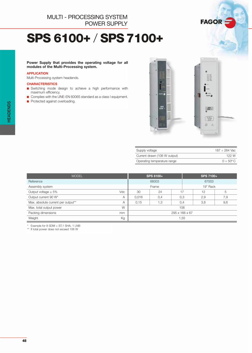
SPS 6100+ / SPS7100+
MULTI - PROCESSING SYSTEMPOWER SUPPLY
Power Supply that provides the operating voltage for allmodules of the Multi-Processing system.
APPLICATIONMulti-Processing system headends.
CHARACTERISTICS■ Switching mode design to achieve a high performance with
maximum efficiency. ■ Complies with the UNE-EN 60065 standard as a class I equipment.■ Protected against overloading.
Supply voltage 187 ÷ 264 Vac
Current drawn (106 W output) 122 W
Operating temperature range 0 ÷ 50º C
* Example for 8 SDM + ST,1 SHA, 1 LNB** If total power does not exceed 106 W
MODEL SPS 6100+ SPS 7100+
Reference 66003 67003
Assembly system Frame 19” Rack
Output voltage ± 5% Vdc 30 24 17 12 5
Output current 90 W* A 0,016 0,4 0,3 2,9 7,9
Max. absolute current per output** A 0,15 1,3 0,4 3,8 9,6
Max. total output power W 106
Packing dimensions mm 295 x 166 x 67
Weight Kg 1,55
HE
AD
EN
DS
49
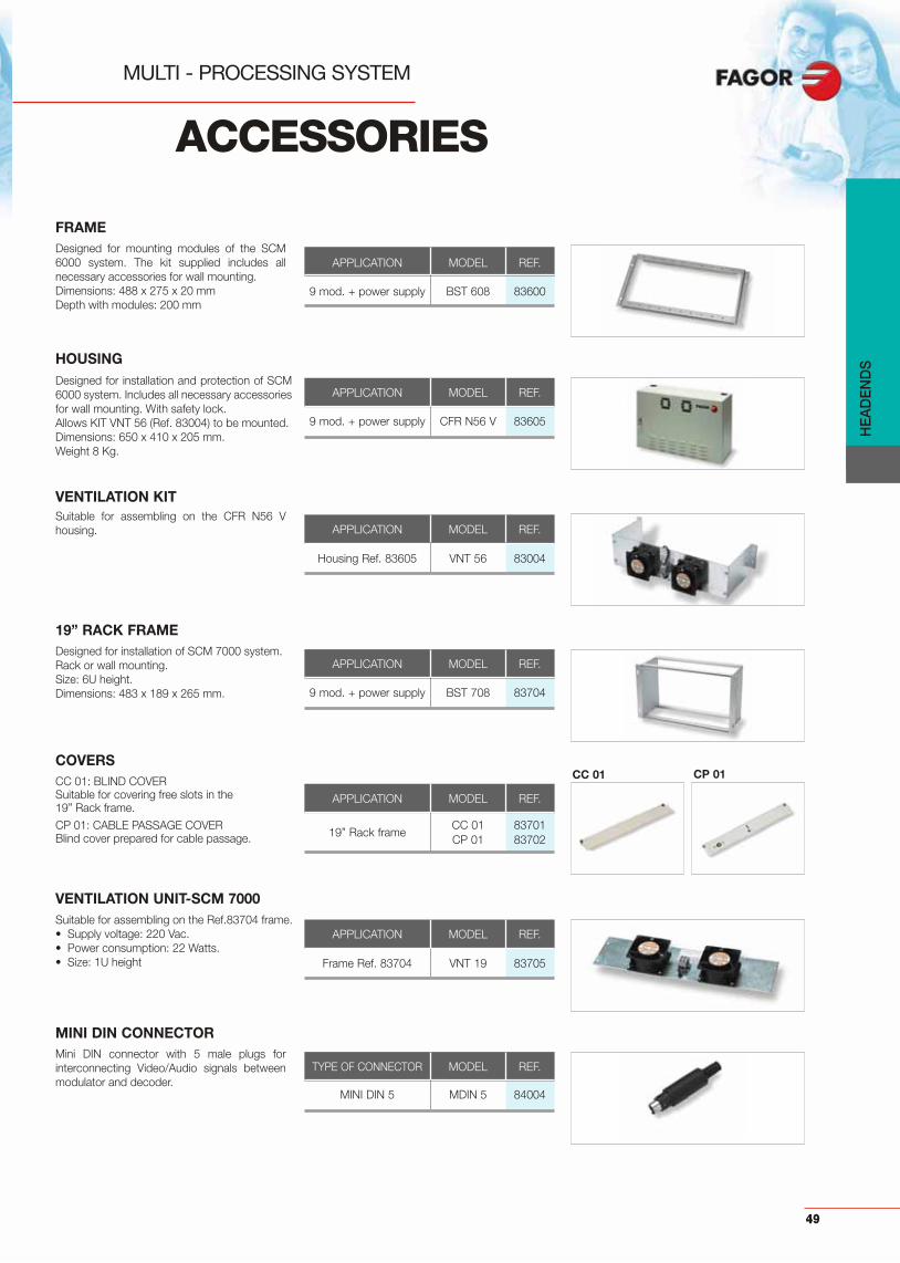
ACCESSORIES
MULTI - PROCESSING SYSTEM
CC 01 CP 01
APPLICATION MODEL REF.
9 mod. + power supply CFR N56 V 83605
HOUSING
19” RACK FRAME
COVERS
Designed for installation and protection of SCM6000 system. Includes all necessary accessoriesfor wall mounting. With safety lock.Allows KIT VNT 56 (Ref. 83004) to be mounted.Dimensions: 650 x 410 x 205 mm.Weight 8 Kg.
Designed for installation of SCM 7000 system.Rack or wall mounting.Size: 6U height.Dimensions: 483 x 189 x 265 mm.
CC 01: BLIND COVERSuitable for covering free slots in the19” Rack frame.
CP 01: CABLE PASSAGE COVERBlind cover prepared for cable passage.
APPLICATION MODEL REF.
Housing Ref. 83605 VNT 56 83004
VENTILATION KITSuitable for assembling on the CFR N56 Vhousing.
VENTILATION UNIT-SCM 7000Suitable for assembling on the Ref.83704 frame.• Supply voltage: 220 Vac.• Power consumption: 22 Watts.• Size: 1U height
APPLICATION MODEL REF.
9 mod. + power supply BST 608 83600
FRAMEDesigned for mounting modules of the SCM6000 system. The kit supplied includes allnecessary accessories for wall mounting.Dimensions: 488 x 275 x 20 mmDepth with modules: 200 mm
APPLICATION MODEL REF.
9 mod. + power supply BST 708 83704
APPLICATION MODEL REF.
CC 01 8370119” Rack frame
CP 01 83702
APPLICATION MODEL REF.
Frame Ref. 83704 VNT 19 83705
MINI DIN CONNECTORMini DIN connector with 5 male plugs forinterconnecting Video/Audio signals betweenmodulator and decoder.
TYPE OF CONNECTOR MODEL REF.
MINI DIN 5 MDIN 5 84004

HE
AD
EN
DS
50
ACCESSORIES
MULTI - PROCESSING SYSTEM
TYPE OF CONNECTOR MODEL REF.
F (m) - F (m) PMD FF 84031
75 F-F COAXIAL BRIDGERigid 75 coaxial bridge for splitting orcombining RF signals.
TYPE OF CONNECTOR MODEL REF.
MINI DIN 5 /CMD EU-ST 84032
Euroconnector
MINI DIN CABLE - EUROCONNECTOR
TYPE OF CONNECTOR MODEL REF.
MINI DIN 5 / 3 RCA CDM 3 RCA 84033
MINI DIN - 3RCA CABLEMini Din 5 / 3RCA cable for connecting Videoand Audio Stereo signals to the modulator.Length: 2 m.
Mini DIN 5 cable - euroconnector forconnecting Video/Audio Stereo signalsbetween modulator and decoder.Length: 2 m.
75 F LOADCoaxial resistive load for loading openconnectors. TYPE OF CONNECTOR MODEL REF.
F (m) CX 75 F 84011
TYPE OF CONNECTOR MODEL REF.
MINI DIN 8 UCF 100 85100
CONTROL UNITUniversal control unit designed forprogramming FAGOR modules.Packing dimensions: 155 x 110 x 50 mm.Weight: 0,1 Kg.

HE
AD
EN
DS
51
MULTI - PROCESSING SYSTEM
APPLICATION EXAMPLES
Nr. DESCRIPTION SCM 6000 SCM 7000
1 Receiver - Modulator - SRM+ Ref. 27660 Ref. 27760
2Amplifier - SHA N Ref. 35016 Ref. 35017
Amplifier - Combiner - SAC N Ref. 35018 Ref. 35019
3 Channel converter via IF - CIF+ Ref. 06410 - 06424 Ref. 07410 - 07424
4 FM Amplifier - AFM Ref. 35004 Ref. 35005
5 Power Supply - SPS+ Ref. 66003 Ref. 67003
6 BSV Modulator - SM+ Ref. 19650 Ref. 19750
7 QPSK - AM transmodulator - SDM+ Ref. 27580 Ref. 27880
8 75 F-F coaxial bridge - PMD FF Ref. 84031
9 Control unit - UCF Ref. 85100
10 75 F load - CX 75F Ref. 84011
11 Cable passage cover - CP 01 — Ref. 83702
12 Power Supply - SPS+ Ref. 66003 Ref. 67003
• Frame - BST 608 Ref. 83600 —
• Housing - CFR N56V Ref. 83605 —
• 19“ Rack frame - BST 708 — Ref. 83704
• Ventilation kit - VNT 56 Ref. 83004 —
• Ventilation unit - VNT 19 — Ref. 83705
AFM SAC N
SRM+ SRM+ SRM+ SDM+ SDM+ SDM+ SDM+ SDM+ SPS+
CIF+ CIF+ CIF+ CIF+ CIF+ CIF+
A A D D D D
SM+ SPS+
FM
OUTPUT (47 ÷ 862 MHz)
UHF UHF SATV SATVSURVEILLANCE
8
6
3
4
2
11
1
5
10
9
7
• 47 ÷ 862 MHz• 3 analogue satellite TV
programs• 4 DTT channels• 2 digital terrestrial TV
programs• 5 digital satellite TV
programs• 1 surveillance channel
12

HE
AD
EN
DS
52
MULTI - PROCESSING SYSTEM
APPLICATION EXAMPLES
OUTPUT(47 ÷ 2150 MHz)
SATVSATV
1
4
2 3
68
7 5
IFL IFL IFL IFL IFL IFA N
+LNB
SHA N SRM+ SRM+ SPS+
• 47 ÷ 2150 MHz• 10 digital SAT TV
transponders• 2 analogue satellite TV
programs
Nr. DESCRIPTION SCM 6000 SCM 7000
1 1st IF SAT Twin Converter - IFL Ref. 06900 Ref. 07900
2 1st IF SAT Amplifier - IFA S Ref. 35914 Ref: 35915
3 Receiver-Modulator - SRM+ Ref. 27660 Ref. 27760
4 Power Supply - SPS+ Ref. 66003 Ref. 67002
5Amplifier - SHA N Ref. 35016 Ref. 35017
Amplifier - Combiner - SAC N Ref. 35018 Ref. 35019
6 Control unit - UCF Ref. 85100
7 75 F-F coaxial bridge - PMD FF Ref. 84031
8 75 F load - CX 75 F Ref. 84011
• Frame - BST 608 Ref. 83600 —
• Housing - CFR N56V Ref. 83605 —
• 19“ Rack frame - BST 708 — Ref. 83704
• Ventilation kit - VNT 56 Ref. 83004 —
• Ventilation unit - VNT 19 — Ref. 83705

HE
AD
EN
DS
53
MULTI - PROCESSING SYSTEM
APPLICATION EXAMPLES
FM
OUTPUT(47 ÷ 2150 MHz)
UHF UHF SATV SATVSURVEILLANCE
13
2
14
6
4
5
8
11
9
13
7
12
10
AFM SAC N CIF+ CIF+
A A
TDM TDM TDM TDM SM+ SPS+
IFL IFL IFL IFL IFL IFL IFL IFL IFA N+ LNB
SPS+
SRM+ SRM+ SRM+ SDM+ SDM+ SDM+ SDM+ SDM+ SPS+
• 47 ÷ 2150 MHz• 16 digital satellite TV
transponders• 3 analogue satellite
TV programs• 4 digital terrestrial TV
programs• 2 digital terrestrial TV
programs• 1 surveillance channel• FM Radio• 5 digital satellite TV
programs
Nr. DESCRIPTION SCM 6000 SCM 7000
1 COFDM-PAL Transmodulator - TDM Ref. 27460 Ref. 27560
2 Receiver - Modulator - SRM+ Ref. 27660 Ref. 27760
3 Amplifier - Combiner - SAC N Ref. 35018 Ref. 35019
4 Channel Converter via IF - CIF+ Ref. 06410 - 06424 Ref. 07410 - 07424
5 FM Amplifier - AFM Ref. 35004 Ref. 35005
6 1st IF SAT Twin Converter - IFL Ref. 06900 Ref. 07900
7 1st IF SAT Amplifier - IFA S Ref. 35914 Ref: 35915
8 VSB Modulator - SM+ Ref. 19650 Ref. 19750
9 QPSK - AM Transmodulator - SDM+ Ref. 27580 Ref. 27880
10 Power Supply - SPS+ Ref. 66003 Ref. 67003
11 75 F-F coaxial bridge - PMD FF Ref. 84031
12 Control unit - UCF Ref. 85100
13 75 F load - CX 75 F Ref. 84011
14 Cable passage cover - CP 01 — Ref. 83702
• Frame - BST 608 Ref. 83600 —
• Housing - CFR N56V Ref. 83605 —
• 19“ Rack frame - BST 708 — Ref. 83704
• Ventilation kit - VNT 56 Ref. 83004 —• Ventilation unit - VNT 19 — Ref. 83705

COMPACT HEADENDQPSK / AM
DiSAT 6 Series
HE
AD
EN
DS
54
Input power 230 V ± 15%
Current drawn (230 Vac) max. 150 W
Operating temperature range 0 ÷ 45º C
QPSK/AM receiver designed for headend conversion of 6digital satellite TV channels to analogue TV in RF. Availablein two versions: DiSAT 6U for UHF channels (C21-C69) andDiSAT 6V for VHF channels (S09-S26).
APPLICATIONSuitable for small and medium sized distributions, giving its RFmodulated output in double sideband. Ideal for use in low costcommunity projects. No need for individual receivers to be installed foreach TV. Functions autonomously in communal areas of buildings,recovering reception automatically in case of electricity cuts or serviceinterruptions.
CHARACTERISTICS■ No need of input splitters.■ Receivers and output channels easily programmable by means
of the integrated programmer with access code.■ Valid for radio program reception.■ High audio and video quality.■ Combiner for mixing TV signals coming from other equipment.■ Independent output level regulation for each channel.■ RS 232 for software updating.■ Satellite signal demultiplexing bridges included.
MODEL DiSAT 6U DiSAT 6V
Reference 86504 86506
LNB / TUNERS
Input frequency MHz 950…2150
Input level dBμV 44 ÷ 77
ACF range MHz ± 3
LNB power VDC 13.0V/18.0V (Max 400 mA) with protection against short circuits
Impedance 75
Return losses dB 9
Step attenuation (in 6th receiver) dB 16
DEMODULATORS
Type of modulation QPSK (SCPC, MCPC)
Symbol rate MBaud 1 ÷ 30
Code Rate, FEC 1/2, 2/3, 3/4, 5/6, 7/8 Automatic
Video: aspect ratio 4:3
Video standard PAL
Mono/stereo audio L+R
TV RF MODULATORS
Modulation AM, DBL
Modulation standard B/G
Frequencies covered MHz 470 ÷ 860 160 ÷ 350
Output channel C21 ÷ 69 S09 ÷ S26
RF Output Level dBμV 90 90
Individual RF output adjustment dB 10
General RF output adjustment dB 20
In-band spurious (with 91 dBμV output level) dBc –60 –54
Impedance 75
Return loss dB 9
GENERAL DATA
Connectors F (f)
Dimensions mm 348 x 337 x 162
Packaging dimensions mm 400 x 330 x 195
Weight Kg 9

HE
AD
EN
DS
55
NEXUM SYSTEMCHANNEL AMPLIFIER
NEX Series
Single channel amplifier, suitable for amplifiying andfiltering of TV signals in MATV headend systems. Theseamplifiers are perfect for working in adjacent channels.
APPLICATIONMedium- to large-sized community digital and analogue TVinstallations located in poor reception areas with big level differencesbetween channels.
CHARACTERISTICS■ Metal chassis (zamak), integrating the input/output connectors to
give the unit great strength.■ High shielding degree.■ High reliability and screening factor due to “F” connectors.■ Modular design that allows channel configuration according to
installation needs.■ The use of filters with high "Q" factor (quality factor) inductive lines
guarantees a high channel selectivity.■ Easy to set-up due to its system of splitting at input and combining
at output.
Supply voltage 24 Vdc
Current drawn 65 mA
Operating temperature range 0 ÷ 50º C
MODEL
Reference
Channels
Max. output level (DIN 45004K) dBμV
Gain dB
Gain adjustment dB@ N±1
Bandwidth MHz
SelectivityPVN–PAN-1PAN–PVN+1 dBPV+20 MHz
Return losses dB
Noise figure dB
Current drawn (24 VDC) mA
Input-Output impedance
Input-Output connectors
Packing dimensions mm
Weight Kg
NEX 401 NEX 402 NEX DAB NEX 403 NEX 445 NEX 545
39102...04 39200 39201 39305...12 39421...69 39521...69
E02...E04 FM 87 ÷ 108 DAB 195 ÷ 223 E05...E12 21...69 21...69
115 115123 (DIN B –35 dB) (DIN B –35 dB) 123 117 125
40 40 35 40 40 50
30 30 30 30 30 3015 — — 15 15 15
7 21 28 7 8 8
@ –15 MHz20 35 23 20 16 1620 @ +15 MHz 20 16 16
>70 30 8 70 >70 >70
9
11 4 5 11 11 11
90 65 65 105 55 110
75
F (f)
195 x 70 x 32
0,45

NEXUM SYSTEMMULTICHANNEL AMPLIFIERS
Multichannel amplifier, suitable for amplifying and filteringof TV signals in MATV headend systems. These amplifiersare perfect for working in adjacent channels.
APPLICATIONMedium- to large-sized community digital and analogue TVinstallations located in poor reception areas with big level differencesbetween channels.
CHARACTERISTICS■ Metal chassis (zamak), integrating the input/output connectors to
give the unit great strength.■ High shielding degree.■ High reliability and screening factor due to “F” connectors.■ Modular design that allows channel configuration according to
installation needs.■ The use of filters with high "Q" factor (quality factor) inductive lines
guarantees a high channel selectivity.■ Easy to set-up due to its system of splitting at input and combining
at output.
NEX Series
MODEL
Reference
Channels
Max. output level dBμV
Gain dB
Gain adjustment dB
Bandwidth MHz
SelectivityPVN–PAN-1PAN–PVN+1 dBPV+20 MHz
Return losses dB
Noise figure dB
Current drawn (24 VDC) mA
Input-Output impedance
Input-Output connectors
Packing dimensions mm
Weight Kg
NEX 545 NEX 545 NEX 545 NEX 5452 channels 3 channels 4 channels 5 channels
39501...20 39580...600 39570 39571
— * — * 66 ÷ 69 65 ÷ 69
112 (2 Ch AM-TV) 111 (3 Ch AM-TV) 109 (4 Ch AM-TV) 108 (5 Ch AM-TV)109 (2 Ch COFDM) 107 (3 Ch COFDM) 106 (4 Ch COFDM) 105 (5 Ch COFDM)
50
30
16 24 32 40
@ N = ch 65 @ N = ch 64— — 16 1630 30 — —30 30 — —
9
11
110
75
F (f)
195 x 70 x 32
0,45
Supply voltage 24 Vdc
Operating temperature range 0 ÷ 50º C
* Different configurations upon request.
HE
AD
EN
DS
56

HE
AD
EN
DS
NEXUM SYSTEM1st IF SAT AMPLIFIER
IFA 400
Equalized amplifier for the 950 to 2300 MHz band. Amplifiesthe 1st IF SAT signal and mixes it with terrestrial channels.
APPLICATIONCommunity digital and analogue satellite TV installations where the1st IF SAT signal has to be distributed.
CHARACTERISTICS■ Metal chassis (zamak), integrating the input/output connectors to
give the unit great strength.■ High shielding degree.■ High reliability and screening factor due to its “F” connectors.■ Easy to set-up due to its system of splitting at input and combining
at output.
Supply voltage 24 (130 mA) Vdc
Current drawn 65 mA
Operating temperature range 0 ÷ 50º C
MODEL IFA 400
Reference 39204
Frequencies covered MHz 950 ÷ 2150
Number of inputs 1st IF 1 (950 ÷ 2150 MHz)
Number of inputs RF 1 (5 ÷ 862 MHz)
Gain (1st IF) dB 40 (950 MHz) 48 (2150 MHz)
Noise figure dB 7
RF signal rejection (1st IF input) dB 40 (5 ÷ 862 MHz)
Through losses RF dB 1,5 (5 ÷ 862 MHz)
Gain adjustment dB 20 (950 ÷ 2150 MHz)
Output level @2150 MHz dBμV 125 (DIN 45004B, DIM –35 dBc)113 (30 transponders, DIM –35 dBc)
Return losses dB 9
Voltage to LNB 13 VDC / 300 mA
Packing dimensions mm 195 x 70 x 32
Weight Kg 0,35
57
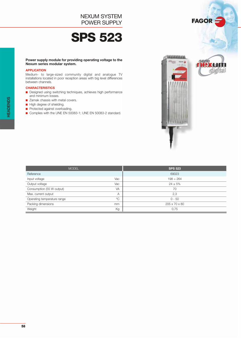
SPS 523
NEXUM SYSTEMPOWER SUPPLY
Power supply module for providing operating voltage to theNexum series modular system.
APPLICATIONMedium- to large-sized community digital and analogue TVinstallations located in poor reception areas with big level differencesbetween channels.
CHARACTERISTICS■ Designed using switching techniques, achieves high performance
and minimum losses.■ Zamak chassis with metal covers.■ High degree of shielding.■ Protected against overloading.■ Complies with the UNE EN 50083-1; UNE EN 50083-2 standard.
MODEL SPS 523
Reference 69023
Input voltage Vac 198 ÷ 264
Output voltage Vac 24 ± 5%
Consumption (55 W output) VA 70
Max. current output A 2,3
Operating temperature range ºC 0 - 50
Packing dimensions mm 205 x 70 x 80
Weight Kg 0,75
HE
AD
EN
DS
58

ACCESSORIES
NEXUM SERIES
TYPE OF CONNECTOR MODEL REF.
F (m) CX 75 F 84011
FRAME
HOUSING
75 F LOAD
Designed for mounting modules of the NexumSeries Modular System. The kit suppliedincludes all necessary accessories for wallmounting.Raster: 40 mm.Dimensions:Ref. 83109: 531 x 139 x 15 mm.Ref. 83110: 747 x 139 x 15 mm.Ref. 83111: 480 x 177 x 70 mm.Ref. 83112: 325 x 140 x 15 mm.
Designed for installation and protection ofNexum Series Modular System. With safetylock.Prepared for the VNT 56 Kit (Ref. 83004) to bemounted.Dimensions:Ref. 83605: 650 x 410 x 205 mm. (7 Kg)Ref. 83604: 790 x 590 x 205 mm. (8 Kg)Ref. 83607: 790 x 250 x 150 mm. (6 Kg)
Coaxial resistive load for loading open connectors.
TYPE OF CONNECTOR MODEL REF.
F (m) - F (m) PMD FFN 84034
75 F-F COAXIAL BRIDGERigid 75 coaxial bridge for splitting or combining RF signals.Raster: 40 mm.
TYPE OF CONNECTOR MODEL REF.
F (f) - F (f) ADF HH 84013
ADAPTERF Female-Female
APPLICATION MODEL REF.
12 mod. + power supply CFR N56V 83605or 8 modules SCM 6000
Housing for 2x18 Nexum,or 1 x 18 Nexum + CFR N218 836041 x 8 SCM 6000
Housing for 1 x 18 Nexum CFR N118 83607
BST N12 & BST N18
BSK N10
CFR N56V
CFR N118
CFR N218
HE
AD
EN
DS
59
TYPE OF CABLE MODEL REF.
CCF 017-N CNR MF 84012
F MALE CONNECTOR F(m) connector for cable (outside diameter 6,8 mm),
APPLICATION MODEL REF
6 mod. + power supply BST N06 83112
12 mod. + power supply BST N12 83109
18 mod. + power supply BST N18 83110
10 mod. + power supplyfor 19” Rack mounting BSK N10 83111

HE
AD
EN
DS
60
ACCESSORIES
NEXUM SERIES
BAND AMPLIFIER• Frequency band: 470 to 862 MHz• Gain: 12 dB• Max. output level: 105 dBuV• Noise figure: 3,5 dB• Band flatness: 2 dB• Power supply: 24V ± 5%• Consumption: < 50 mA
TYPE OF CONNECTOR MODEL REF.
F(f)-F(m) ABF 012 85053
SUPPLY INJECTOR• Frequency band: 5 to 2150 MHz• Return losses: -10 dB • Through losses: 0,5 dB• DC pass: 1A
TYPE OF CONNECTOR MODEL REF.
F(f)-F(m) ICF 001 85051
MODULE ADAPTION KIT
POWER SUPPLY ADAPTION KIT
For adaption to a SCM 5000 Frame. Includes:• 1 metallic support with screws.• 2 power supply cables.• 2 F-F coaxial bridges.
For adaption to a SCM 5000 Frame.Includes:• 1 metallic support with screws.• 1 power supply cable.
APPLICATION MODEL REF.
SCM 5000 NEX KIT 83706
APPLICATION MODEL REF.
SCM 5000 SPS KIT 83707
SCM 300 MODULE CONNECTIONS
SCM 300 POWER SUPPLY CONNECTIONS
Connections to install Nexum model in SCM 300 module.
Connections to install Nexum power supply in SCM 300 module.
APPLICATION MODEL REF.
SCM 300 CNX 300M 83708
APPLICATION MODEL REF.
SCM 300 CNX 300F 83709

HE
AD
EN
DS
61
SAT 1
IFA IFA NEX NEX NEX NEX NEX NEX NEX NEX NEX NEX
SPS
SAT 2 UHF 1 UHF 2 UHF 3 DAB FM
DXR 2D(Ref. 86242)
Nr. DESCRIPTION Nexum Series
1 Channel amplifier - NEX —
2 1st IF SAT amplifier - IFA Ref. 39204
3 Amplifier FM radio - NEX 402 Ref. 39200
4 Amplifier DAB radio - NEX DAB Ref. 39201
5 Power supply - SPS Ref. 69023
6 75 F-F coaxial bridge - PMD FFN Ref. 84034
7 Load - CX 75F Ref. 84011
8 Splitter- Combiner - DRX 2D Ref. 86242
2
5
1
3
6 74
• 47 ÷ 2150 MHz• 2 polarities of
1st IF SAT • 8 terrestrial channels,
analogue or digital• FM radio• DAB radio
• 47 ÷ 2150 MHz• 1 polarity of 1st IF SAT • DTT Channels: 66 to 69• 3 terrestrial channels,
analogue or digitalSAT
IFA NEX66-69
NEX NEX NEX
SPS
UHF
RF + SAT
Nr. DESCRIPTION Nexum Series
1 Multichannel amplifier - NEX 545 Ref. 39570
2 Channel amplifier - NEX —
3 1st IF SAT amplifier - IFA Ref. 39204
4 Power supply - SPS Ref. 69023
5 75 F-F coaxial bridge - PMD FFN Ref. 84034
6 Load - CX 75F Ref. 84011
3
1
4
2
65
SAT 1 RF SAT 2
SAT 1+ RF SAT 2 + RF
8
NEXUM SYSTEM
APPLICATION EXAMPLES
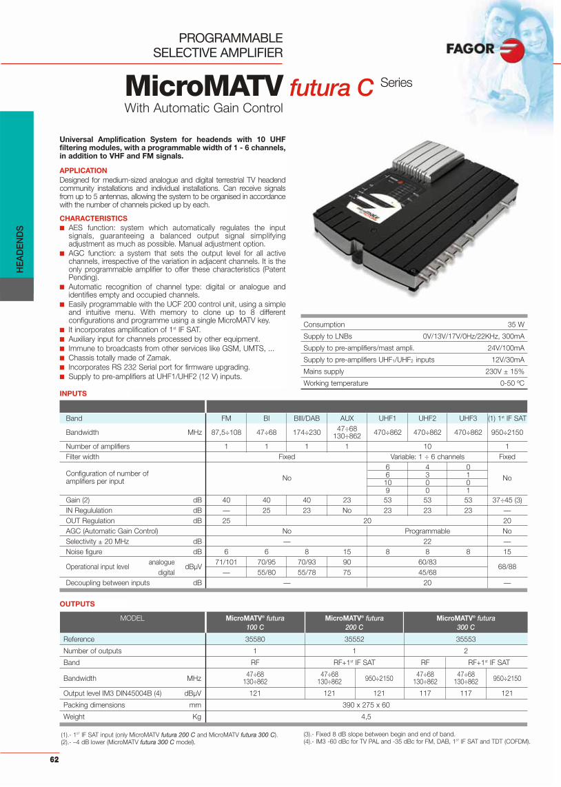
HE
AD
EN
DS
62
PROGRAMMABLE SELECTIVE AMPLIFIER
MicroMATV futura CWith Automatic Gain Control
Consumption 35 W
Supply to LNBs 0V/13V/17V/0Hz/22KHz, 300mA
Supply to pre-amplifiers/mast ampli. 24V/100mA
Supply to pre-amplifiers UHF1/UHF2 inputs 12V/30mA
Mains supply 230V ± 15%
Working temperature 0-50 ºC
Universal Amplification System for headends with 10 UHFfiltering modules, with a programmable width of 1 - 6 channels,in addition to VHF and FM signals.
APPLICATIONDesigned for medium-sized analogue and digital terrestrial TV headendcommunity installations and individual installations. Can receive signalsfrom up to 5 antennas, allowing the system to be organised in accordancewith the number of channels picked up by each.
CHARACTERISTICS■ AES function: system which automatically regulates the input
signals, guaranteeing a balanced output signal simplifyingadjustment as much as possible. Manual adjustment option.
■ AGC function: a system that sets the output level for all activechannels, irrespective of the variation in adjacent channels. It is theonly programmable amplifier to offer these characteristics (PatentPending).
■ Automatic recognition of channel type: digital or analogue andidentifies empty and occupied channels.
■ Easily programmable with the UCF 200 control unit, using a simpleand intuitive menu. With memory to clone up to 8 differentconfigurations and programme using a single MicroMATV key.
■ It incorporates amplification of 1st IF SAT.■ Auxiliary input for channels processed by other equipment.■ Immune to broadcasts from other services like GSM, UMTS, ...■ Chassis totally made of Zamak.■ Incorporates RS 232 Serial port for firmware upgrading.■ Supply to pre-amplifiers at UHF1/UHF2 (12 V) inputs.
Series
Band FM BI BIII/DAB AUX UHF1 UHF2 UHF3 (1) 1st IF SAT
Bandwidth MHz 87,5÷108 47÷68 174÷230 47÷68 470÷862 470÷862 470÷862 950÷2150130÷862Number of amplifiers 1 1 1 1 10 1Filter width Fixed Variable: 1 ÷ 6 channels Fixed
No
6 4 0
NoConfiguration of number of 6 3 1amplifiers per input 10 0 0
9 0 1Gain (2) dB 40 40 40 23 53 53 53 37÷45 (3)IN Regululation dB — 25 23 No 23 23 23 —OUT Regulation dB 25 20 20AGC (Automatic Gain Control) No Programmable NoSelectivity ± 20 MHz dB — 22 —Noise figure dB 6 6 8 15 8 8 8 15
Operational input level analogue
dBμV71/101 70/95 70/93 90 60/83
68/88digital — 55/80 55/78 75 45/68
Decoupling between inputs dB — 20 —
(1).- 1ST IF SAT input (only MicroMATV futura 200 C and MicroMATV futura 300 C).(2).- –4 dB lower (MicroMATV futura 300 C model).
(3).- Fixed 8 dB slope between begin and end of band.(4).- IM3 -60 dBc for TV PAL and -35 dBc for FM, DAB, 1ST IF SAT and TDT (COFDM).
MODEL MicroMATV® futura MicroMATV® futura MicroMATV® futura100 C 200 C 300 C
Reference 35580 35552 35553
Number of outputs 1 1 2
Band RF RF+1st IF SAT RF RF+1st IF SAT
Bandwidth MHz 47÷68 47÷68 950÷2150 47÷68 47÷68 950÷2150130÷862 130÷862 130÷862 130÷862
Output level IM3 DIN45004B (4) dBμV 121 121 121 117 117 121
Packing dimensions mm 390 x 275 x 60
Weight Kg 4,5
OUTPUTS
INPUTS
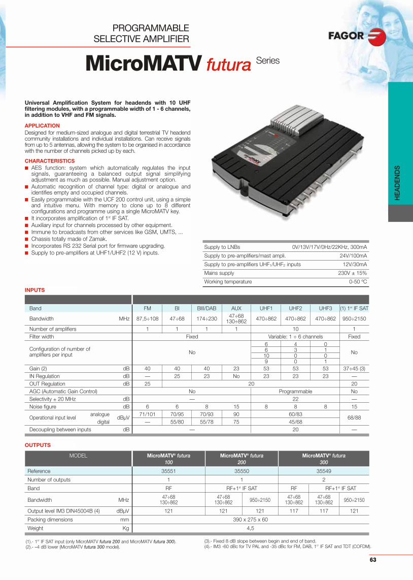
HE
AD
EN
DS
63
PROGRAMMABLE SELECTIVE AMPLIFIER
Supply to LNBs 0V/13V/17V/0Hz/22KHz, 300mA
Supply to pre-amplifiers/mast ampli. 24V/100mA
Supply to pre-amplifiers UHF1/UHF2 inputs 12V/30mA
Mains supply 230V ± 15%
Working temperature 0-50 ºC
Band FM BI BIII/DAB AUX UHF1 UHF2 UHF3 (1) 1st IF SAT
Bandwidth MHz 87,5÷108 47÷68 174÷230 47÷68 470÷862 470÷862 470÷862 950÷2150130÷862Number of amplifiers 1 1 1 1 10 1Filter width Fixed Variable: 1 ÷ 6 channels Fixed
No
6 4 0
NoConfiguration of number of 6 3 1amplifiers per input 10 0 0
9 0 1Gain (2) dB 40 40 40 23 53 53 53 37÷45 (3)IN Regulation dB — 25 23 No 23 23 23 —OUT Regulation dB 25 20 20AGC (Automatic Gain Control) No Programmable NoSelectivity ± 20 MHz dB — 22 —Noise figure dB 6 6 8 15 8 8 8 15
Operational input level analogue
dBμV71/101 70/95 70/93 90 60/83
68/88digital — 55/80 55/78 75 45/68
Decoupling between inputs dB — 20 —
(1).- 1ST IF SAT input (only MicroMATV futura 200 and MicroMATV futura 300).(2).- –4 dB lower (MicroMATV futura 300 model).
(3).- Fixed 8 dB slope between begin and end of band.(4).- IM3 -60 dBc for TV PAL and -35 dBc for FM, DAB, 1ST IF SAT and TDT (COFDM).
MODEL MicroMATV® futura MicroMATV® futura MicroMATV® futura100 200 300
Reference 35551 35550 35549
Number of outputs 1 1 2
Band RF RF+1st IF SAT RF RF+1st IF SAT
Bandwidth MHz 47÷68 47÷68 950÷2150 47÷68 47÷68 950÷2150130÷862 130÷862 130÷862 130÷862
Output level IM3 DIN45004B (4) dBμV 121 121 121 117 117 121
Packing dimensions mm 390 x 275 x 60
Weight Kg 4,5
OUTPUTS
Universal Amplification System for headends with 10 UHFfiltering modules, with a programmable width of 1 - 6 channels,in addition to VHF and FM signals.
APPLICATIONDesigned for medium-sized analogue and digital terrestrial TV headendcommunity installations and individual installations. Can receive signalsfrom up to 5 antennas, allowing the system to be organised in accordancewith the number of channels picked up by each.
CHARACTERISTICS■ AES function: system which automatically regulates the input
signals, guaranteeing a balanced output signal simplifyingadjustment as much as possible. Manual adjustment option.
■ Automatic recognition of channel type: digital or analogue andidentifies empty and occupied channels.
■ Easily programmable with the UCF 200 control unit, using a simpleand intuitive menu. With memory to clone up to 8 differentconfigurations and programme using a single MicroMATV key.
■ It incorporates amplification of 1st IF SAT.■ Auxiliary input for channels processed by other equipment.■ Immune to broadcasts from other services like GSM, UMTS, ...■ Chassis totally made of Zamak.■ Incorporates RS 232 Serial port for firmware upgrading.■ Supply to pre-amplifiers at UHF1/UHF2 (12 V) inputs.
INPUTS
MicroMATV futura Series

HE
AD
EN
DS
64
FAGOR CONTROL UNIT
UCF 200
Control unit valid for programming a MicroMATV pro and aMicroMATV futura by means of a simple and intuitive menu.With memory for cloning up to 8 different configurationsand one-key programming of more than one MicroMATV.Includes protector sleeve.
BUS USB ADAPTER
BUS ADAPTER 1.7
Communication interface between computer and UCF 200control unit for:■ Automatic programming of the MicroMATV Futura by means of the
"Programmation Guide".■ Recording of configurations/installations in the computer.■ Export of configurations to the UCF 200 control unit for future
installations.
MODEL BUS ADAPTER 1.7
Reference 85103
Packing dimensions mm 165 x 65 x 50
Weight Kg 0,2
MODEL UCF 200
Reference 85102
Display Alphanumerical, (2 x 16 characters)
Packing dimensions mm 46 x 18 x 14
Weight Kg 0,2

HE
AD
EN
DS
65
PROGRAMMABLE SELECTIVE AMPLIFIER
MICROMATV® plus Series
Universal amplification system capable of independentlyprocessing up to 10 TV channels (UHF and VHF), as well asthe FM signal.
APPLICATIONSuitable for community headends installations of digital and analogueterrestrial TV. The unit is designed to receive signals coming from upto 5 different antennas in medium-to-individual sized installations.The system can be configured according to the number of channelspicked up by each antenna.
CHARACTERISTICS■ Includes the Automatic Equalization System “AES”, an exclusive
function that simplifies the setting-up, since it automatically adjuststhe input signals, guaranteeing a perfect output signal. MicroMATVplus can also be manually adjusted.
■ Easy to programme through an external Control Unit, UCF 100. Allfunctions are automatically memorised and controlled by a FAGORMicroprocessor.
■ Includes a visual level indicator. ■ The amplifier has a 24V output and an auxiliary TV signal input.
Supply voltage 230 Vac –15 + 10 %
Current drawn 21 W
Operating temperature range 0 ÷ 50º C
MICROMATV® plus MICROMATV® plus MICROMATV® plusMODEL 1.9 2.8 5.5
Reference 35465 35485 35445
BI / BIII UHF FM BI / BIII UHF FM BI/BIII BIII UHF FMNumber of inputs 1 3 1 2 3 1 2 1 2 1
Number of channels 1 9 FM 2 8 FM 2 3 5 FM
Gain dB 43 53 35 43 53 35 43 53 35
Independent regulation per channel dB 25 / 20 20 — 25 / 20 20 — 25 / 20 20 —
General regulation dB 20 25 20 25 20 25
Selectivity (± 20 MHz) dB 25 — 25 — 25 —
Noise figure (typ.) dB 10 5,5 6 10 5,5 6 10 5,5 6
Max. input level dBμV 95 85 101 95 85 101 95 85 101
Min input level for S/N >45 dB BI 60BIII dBμV 57(opt. picture quality) UHF 53
Operating input level BI 70 ÷ 95BIII dBμV 70 ÷ 90(automatic equalization AES) UHF 60 ÷ 80
TV auxiliary input level dBμV 90
Auxiliary input frequency range MHz 47 - 68; 130 - 862
Auxiliary input gain dB 17
Output level DIN 45004B (– 60 dB)* dBμV 116
IM2 (-60 dB) dBμV 116
Output level: 10 channels dBμV 109
Isolation between inputs UHF - UHF dB >30UHF - VHF /FM >60
24 Vdc output mA 30
Packing dimensions mm 345 x 280 x 87
Weight Kg 3
*FM: DIN 45004B (–30 dB).

HE
AD
EN
DS
66
PROGRAMMABLE SELECTIVE AMPLIFIER
MICROMATV® plus N Series
Universal amplification system capable of independentlyprocessing up to 10 TV channels (UHF and VHF), as well asthe FM signal. This programmable amplification systemallows UHF filters to function in either single or dualchannel mode, which makes it an excellent solution forfuture digital terrestrial TV transmissions. In addition to itsfrequency flexibility, each of the MicroMATV plus N’s UHFchannels can be programmed in either single or dual chan-nel mode, in installation itself.
APPLICATIONDesigned for community headend installations of digital terrestrial TV.
CHARACTERISTICS■ Easy to programme through an external Control Unit, UCF 100.
All functions are automatically memorised and controlled by aFAGOR Microprocessor.
■ Includes a visual level indicator. ■ The amplifier has a 24V output and an auxiliary TV signal input.
Supply voltage 230 Vac –15 + 10 %
Current drawn 21 W
Operating temperature range 0 ÷ 50º C
MICROMATV® plus N MICROMATV® plus NMODEL 1.9 2.8
Reference 35467 35487
BI / BIII UHF FM BI / BIII UHF FMNumber of inputs 1 3 1 2 3 1
Number of channels (filters) 1 18 (9) FM 2 16 (8) FM
Gain dB 43 53 35 43 53 35
Independent regulation per channel dB 25 / 20 20 — 25 / 20 20 —
General regulation dB 20 25 20 25
Selectivity (± 24 MHz) dB 20 — 20 —
Noise figure (typ.) dB 10 5,5 6 10 5,5 6
Max. input level dBμV 95 85 101 95 85 101
Min input level for S/N >45 dB BI 60BIII dBμV 57(opt. picture quality) UHF 53
Operating input level BI 70 ÷ 95BIII dBμV 70 ÷ 90(automatic equalization AES) UHF 60 ÷ 80
Auxiliary TV input level dBμV 90
Auxiliary TV input frequency range MHz 47÷ 68; 130 ÷ 862
Auxiliary TV input gain dB 17
Output level DIN 45004B (–60 dB)* dBμV 116
IM2 (-60 dB) dBμV 116
Output level: 10 channels dBμV 109
Isolation between inputs UHF - UHF dB >30UHF - VHF /FM >60
24 Vdc output mA 30
Packing dimensions mm 345 x 280 x 87
Weight Kg 3
*FM: DIN 45004B (–30 dB).
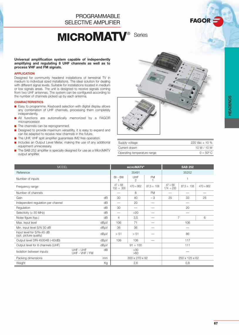
PROGRAMMABLE SELECTIVE AMPLIFIER
67
MICROMATV® Series
Universal amplification system capable of independentlyamplifying and regulating 8 UHF channels as well as toprocess VHF and FM signals.
APPLICATIONDesigned for community headend installations of terrestrial TV inmedium to individual sized installations. The ideal solution for dealingwith different signal levels. Suitable for installations located in mediumor low signals areas. The unit is designed to receive signals comingfrom two UHF antennas. The system can be configured according tothe number of channels picked up by each antenna.
CHARACTERISTICS■ Easy to programme. Keyboard selection with digital display allows
any combination of UHF channels, processing them completelyindependently.
■ All functions are automatically memorized by a FAGORmicroprocessor.
■ The channels can be reprogrammed.■ Designed to provide maximum versatility, it is easy to expand and
can be adapted to receive new channels in the future.■ The UHF, VHF split amplifier guarantees IM2 free operation.■ Includes an Output Level Meter, making the use of any additional
equipment unnecessary.■ The SAB 252 amplifier is specially designed for use as a MicroMATV
output amplifier.
Supply voltage 220 Vac ± 10 %
Current drawn 10 W / 10 W
Operating temperature range 0 ÷ 50º C
MODEL MICROMATV® SAB 252
Reference 35491 35252
BI - BIII UHF FMNumber of inputs 1 2 1 1
47 ÷ 68 470 ÷ 862 87,5 ÷ 108 47 ÷ 68 87,5 ÷ 108 470 ÷ 862Frequency range 132 ÷ 300 174 ÷ 230
Number of channels — 8 FM — — —
Gain dB 30 40 – 3 25 33 25
Independent regulation per channel dB — 20 — —
Regulation dB 30 — — 20
Selectivity (± 20 MHz) dB — >20 — —
Noise figure (typ.) dB 4 3,5 — 7 6
Max. input level dBμV 106 71 — 106
Min. input level S/N 30 dB dBμV 36 36 — —
Input level for S/N<45 dB dBμV > 51 > 51 — 86(opt. picture quality)
Output level DIN 45004B (–60dB) dBμV 106 106 — 117
Output level for 8 channels (UHF) dBμV 91 ÷ 100 111
UHF - UHF dB >30 —Isolation between inputs UHF - VHF / FM >60
Packing dimensions mm 300 x 270 x 92 250 x 125 x 62
Weight Kg 2,6 0,8
HE
AD
EN
DS

HE
AD
EN
DS
68
Band amplification system with separate VHF and UHFsignal processing, to reduce the IM2 products.
APPLICATIONThe different models in the SAB series cover a wide range of applica-tions:SAB 401/SAB 402can be used as a distribution amplifier, or anextension amplifier for collectives.
SAB 401 is designed for working in high temperature environments.
SAB 304/SAB 404, suitable for use as a band amplifier forcommunities.
SAB 301/SAB 301-A, broadband amplifiers which allow a completeprocessing of all TV channels, from 47 to 862 MHz. They can also beused as final amplifier in CATV network.
CHARACTERISTICS■ The circuit is housed in a single-part metal case which includes all
the input-output connectors.■ It has shielding at the top and bottom. ■ High level of mechanical rigidity and complete protection against
electrical interference.Supply voltage 230 Vac –10 % +15%
Current drawn 10 VA
Operating temperature range 0 ÷ 50º C
MODEL SAB 304 SAB 404 SAB 401** SAB 402 SAB 301 SAB 301-A
Reference 35304 35404 35415 35402 35301 35302
Number of inputs 4 4 1 1 1 1
Band coverage BI / FM / BIII / UHF BI / FM / BIII / UHF BI, FM, BIII*, UHF BI, FM, BIII*, UHF 47 ÷ 862 MHz 87,5 ÷ 862 MHz
Output levelDIN 45004B (–60 dB) dBμV 109 117 111 117 116 116
Gain dB 30 40 / 33 / 40 / 40 40, 33, 40, 40 40, 33, 40, 40 28 ÷ 35 28 ÷ 35
Input and output 75 75 75 75 75 75impedance
Noise figure dB 5 5 7, 7, 7, 6 7, 7, 7, 6 12...8 12...8
Regulation dB 20 20 20 20 20 20
Tilt regulation dB — — — — 0 ÷ 11 0 ÷ 11
Return pathcovered band MHz — — — — 5 ÷ 30 5 ÷ 65
Return pathinsertion losses dB — — — — – 3,5 – 3,5
Packingdimensions mm 250 x 125 x 62
Weight Kg 0,8
BAND AND DISTRIBUTIONAMPLIFIERS
SAB Series
* BIII : 132 - 300 MHz (S 05 - S 20)** With + 24 V (20 mA) auxiliary output

HE
AD
EN
DS
69
TYPE OF CONNECTOR MODEL REF.
F (f) - F (m) FT 110 F 85030
TRAP FILTER (BI)Insertion losses: <1 dBAttenuation: 20 dBSelectivity: 2 dB ( ± 12 MHz)Thermal drift: 20 KHz / oC
TYPE OF CONNECTOR MODEL REF.
F(f)-F(m) FTF 245 85052
TYPE OF CONNECTOR MODEL REF.
MINI DIN 8 UCF 100 85100
TYPE OF CONNECTOR MODEL REF.
F(f)-F(m) ICF 001 85051
DOUBLE TRAP FILTER
BAND AMPLIFIER
SUPPLY INJECTOR
CONTROL UNIT
Frequency band: 470 ÷ 862 MHzIn band return losses (out of notch filter): >10 dBRejection at central frequency (Fc): 18 dB at470 MHz / 10 dB at 862 MHzRejection at Fc ± 12 MHz: 2 dB In band through losses: <1 dBDC pass: 1 A
Frequency band: 470 ÷ 862 MHzGain: 12 dBFlatness: 2 dBNoise figure: 3,5 dBPower supply: 24 V ± 5%Consumption: <50 mAOutput level:
• ABF 012: 98 dBμV• AB 012 T: 105 dBμV
AB 012 T: telepowered
Frequency band: 5 ÷ 2150 MHzReturn losses: –10 dBThrough losses: 0,5 dBDC pass: 1 A
External programming unit.Packing dimensions: 155 x 110 x 50 mm.Weight: 0,1 Kg.
MICROMATV® SERIES
ACCESSORIES
TYPE OF CONNECTOR MODEL REF.
F(f)-F(m) ABF 012 85053
F(f)-F(m) AB 012 T 85027
TYPE OF CONNECTOR MODEL REF..
F(f)-F(m) ATF 020 85050
ADJUSTABLE ATTENUATORFrequency band: 5 ÷ 2150 MHzReturn losses: –10 dBThrough losses: 0,5 a 20 dBDC pass (0-22 KHz): 1 A
APPLICATION MODEL REF.
MICROMATVplusCRF MMP 83203
MICROMATV + SAB 252
HOUSINGDesigned for installation and protection of system elements. Includes all necessary accessories for wall mounting. Safety lock provided. Dimensions: 500 x 360 x 90 mm.Weight: 1,7 Kg.
TYPE OF CONNECTOR MODEL REF.
F (f) - F (m) FT 130 F 85023
TRAP FILTER (BIII)Insertion losses: <1 dBAttenuation: 20 dBSelectivity: 2 dB (± 12 MHz)Thermal drift: 20 KHz / oC

HE
AD
EN
DS
70
MICROMATV SERIES
APPLICATION EXAMPLES
UHF1
FMFTF 245
FT 130 F
UHF2
VHF
SALIDA
UHF UHF FM VHF
@ktive
ICF 001
OUTPUT
SAB 304
SAB 401 / SAB 402SAB 301/SAB 301-A
SALIDA
Main Line
70 dBμV
VHF B III
VHF B I
FM UHF
FM UHF UHF UHF VHF
UCF 100
SALIDA
FM
UHF1
UHF2
UHF3
VHF1 FT 110 F
FTF 245
ABF 012
MICROMATV plus MICROMATV futura 100 + Disat 6
UHF UHF UHF BIII FM
RF
SAT
UCF 200
DISAT 6
AUX
MICROMATV + SAB 252
AMB 800
IC N001F
@ktive
UHF
UCF 200
UHF UHF DAB FM SAT1
SAT2
ABF 012
CX 75 F
RF+ 1 ST IF SATRF+ FI SAT 2
@ktive
IFA 2000 N
MicroMATV futura 300 + IFA 2000N

BAND AND DISTRIBUTIONAMPLIFIERS
SABAL Series
Amplifiers specially designed for distribution of TV signalsup to 862 MHz or 2300 MHz.
APPLICATIONDesigned to work under adverse weather conditions, where a robustamplifier is needed.
CHARACTERISTICS■ Their circuit is integrated in a Zamak box, which ensures correct
operation of the amplifier.■ The DA 353 and WBA 433 models allow return path operation and
have slope control for the direct way.■ The HA 405 model is specially designed for amplifying both
analogue and DTT signals coming from several antennas. It has 5inputs with independent regulation and 40 dB gain.
■ The amplifier has been optimised by specific circuits which protectit against telecommunications services on adjacent frequencybands.
■ Built-in switch mode power supply.
Supply voltage 230 Vac ± 15 %
Power consumption <12VA
Operating temperature range 0 ÷ 50º C
*950÷2300 MHz: IM3 at –35 dB47÷862 MHz: IM3 at –60dB
HA 405 DA 353 DA 353 A DA 354 DA 354 A WBA 433 WBA 433 A
35945 35920 35922 35924 35925 35930 35932
BI FM BIII UHF1 1 1 2 1 1 1 1 1 1
47-68 87,5-108 174-230 470-862 5÷30 47÷862 5÷66 47÷862 5÷30 47÷862 5÷66 47÷862 5÷30 47÷862 950÷2300 5÷66 47÷862 950÷2300
116 117 116 117 116 117 121(IM2= 117 121(IM2= — 116 117 — 116 117115dBμV) 115dBμV)
75
10 15 10 15 10 15 10 15 10 15 10 6 15 10 6
40 30 40 40 15 35 15 35 15 35 15 35 – 2 35 34 - 41 – 2 35 34 - 41
20 20 20 20 20 20 20 20 20 20 20 20 — 20 20 — 20 20
— — — 20 — 20 — 20 — 20 — 20 — — 20 —— — — — — — — — — — — — 7/14 — — 7/14
1 OUT 1 IN-1 OUT 1 IN-1 OUT 1 IN-1 OUT 1 IN-1 OUT 1 IN-1 OUT 1 IN-1 OUT
30
4,5 5,5 7,5 6,5 9 6 9 6 9 6 9 6 — 6,5 8,5 — 6,5 8,5
F (f)
IP63
280 x 175 x 60
3,1
MODEL
Reference
Number of inputs
Band covered MHz
Max. output dBμVlevel*
Input/output impedance
Return losses dB
Gain dB
Level regulation dB
Equalisation- Variable dB- Switchable
TEST output dB
TEST output dBattenuation
Noise figure (typ.) dB
Input/output connectors
Weather protection
Packing mmdimensions
Weight Kg
HE
AD
EN
DS
71

72
HE
AD
EN
DS
Double extension amplifier specifically designed toCommunity satellite TV installations with IF processors.
APPLICATIONValid for a two-cable system with two independent satellite TV circuitsand a common one for terrestrial TV, in addition to the return path.
CHARACTERISTICS■ The 1st IF SAT signals from inputs 1/2 and the terrestrial signal from
input 1 are amplified and distributed to their two outputs.■ Has an equaliser for each satellite signal (0-20 dB regulation) with
selectable pre-emphasis from 7 to 14 dB.■ Has a double TEST socket for each output with 30 dB attenuation.■ Controls ARE protected under the front cover.■ Integrates a switch mode power supply to reduce the inside
temperature and help extend the life of the equipment.■ Housed in a metal case, with F connectors.
D WBA 415
DOUBLE EXTENSIONAMPLIFIER
MODEL D WBA 415
Reference 35934
Number of inputs 2
Number of outputs 2+2 test
Connectors F (f)
1st IF SAT frequency range MHz 950 ÷ 2.150
1st IF SAT output level dBμV 125 (DIN 45004B ; IM3 –35 dB)
1st IF SAT gain dB 34 ÷ 41 / 950 ÷ 2.150
1st IF SAT gain regulation dB 15
1st IF SAT tilt selection dB 7 / 14
IF input and output adaptation dB 6
Noise figure dB 8,5
RF frequency range MHz 47÷ 862
RF output level dBμV 117 (DIN 45004B; IM3 –60)115 (3p=; IM3 –52dB)
RF gain dB 35
RF gain regulation dB 20
RF tilt regulation dB 0 ÷ 18
RF input and output regulation dB 10
Noise figure dB 8
Return channel MHz 5 ÷ 30
Return channel gain dB –2
Test output level dB –30
Protection rating IP63
Power supply V 230 ± 15 %
Consumption W 17
Operating temperature ºC –10 ÷ 50
Packing dimensions mm 280 x 175 x 60
Weight Kg 3,2

HE
AD
EN
DS
73
IFA 2000 N
1st IF SATAMPLIFIER
Amplifies the 1st IF SAT signal and combines it withterrestrial channels. It has one input for amplifying the IFsignal and another input for the RF signal.
APPLICATIONCommunity Satellite TV installations with IF processors.
CHARACTERISTICS■ A high performance RF / 1st IF SAT diplexer guarantees a noise
free terrestrial TV reception.■ The 1st IF SAT amplification with positive slope (more gain in high
frequencies: 8 dB) to compensate the cable attenuation, allowsdistribution of the 1st IF SAT signal to more users.
■ It provides optional supply voltage for the LNB (+13 Vdc; 22KHz).■ Power supply included.
WEATHERPROOF HOUSING
MODEL CFR 20
Reference 83602
Packing dimensions mm 330 x 285 x 190
Weight Kg 2,45
Supply voltage 220 +15% –10% Vac
Power consumption a 220 V 15VA
Operating temperature range 0 ÷ 50º C
MODEL IFA 2000 N
Reference 35904
Input/output connectors F (f)
Number of inputs One 1st IF SAT input + one RF input
LNB DC pass voltage (1st IF SAT input) mA 13 Vdc / 300 mA + 0,8 Vpp 22 Khz (ON / OFF: 22 KHz)
1st IF SAT frequency range MHz 950 ÷ 2300
1st IF SAT input rejection dB 40 (15 ÷ 862 MHz)
RF frequency range MHz 15 ÷ 862
RF through losses dB 1,5
Output band coverage (1st IF SAT + RF) MHz 15 ÷ 2300
42 (950 MHz)1st IF SAT gain dB 50 (2150 MHz)
1st IF SAT gain regulation dB 17
125 (DIN 45004B, DIN -35 dBc)Output level @ 2150 MHz dBμV 113 (30 transponders, DIN -35 dBc)
Packing dimensions mm 272 x 166 x 45Weight Kg 1,7

74
HE
AD
EN
DS
DIGITAL TERRESTRIAL RECEIVER
Operating temperature 0-40º C
Packing dimensions 330 x 220 x 70
Weight 1,4 kg.
MODEL Tedi 200
Reference 86511POWER SUPPLYPower supply voltage AC 175~240V; 50/60HzConsumption 8 W MAX.Max. Current +5Vdc 50 mAHARDWARETunerInput impedance 75 OhmRF input connector IEC female, 9,5 mmRF output connector IEC male, 9,5 mmInput frequency 47~68 MHz (BI) 174~230 MHz (BIII) 470~862 MHz (UHF)Input levels –80 dBm a –20 dBm (29 dBμV a 89 dBμV)ConnectorTV SCART connector CVBS, RGB, Audio L/RVCR SCART connector: CVBS in-out, Audio L/R in-outRCA outputs Video (CVBS) x 1, Audio L x 1, Audio R x 1, Audio S/P DIF x 19 Pin Sub-D (male): RS 232SYSTEMConstellation QPSK, 16QAM, 64QAMTransmission mode 2K / 8K FFTFEC 1/ 2, 2/3, 3/4, 5/6, y 7/8Guard interval 1/4, 1/8, 1/16, 1/32Transport Stream MPEG-2 ISO/IEC 13818-1Input Rate Máx. 60 M bit/sVideo Resolution 720 x 576 (PAL) 720 x 489 (NTSC)Video Format 4:3, 16:9MPEG decoder MPEG-1, MPEG-2 ISO/IEC 13818-1 Layer I&IIAudio Mode Left / Right / StereoVideo output impedance 75 OhmVideo output level 1 VppAudio output impedance: 600 OhmAudio output level: 2 Vrms
Tedi 200
Reduced size, carefully designed DTT receiver, withON/OFF connector for energy savings. Also has automaticchannel search and memorizes the last tuned channel.Multiple functions and connector options.
APPLICATIONReception of free digital terrestrial channels with no need to changeTV.
CHARACTERISTICS■ DVB-T compliance.■ Electronic Programme Guide (EPG) for 14 days.■ Teletext and DVB subtitles.■ OSD menu in 11 languages.■ 8 favourites programme lists.■ Language selection ■ Freeze image, zoom function...■ Mosaic function■ Screen format: 16:9 or 4:3> Parental control using a secret code.■ Freeze image, zoom function...■ 4-digit display, clock.■ S/PDIF digital audio output■ Video, Audio and Stereo Audio Output.■ Two SCART connectors: TV and VCR.■ 5 V power supply for indoor antenna.■ Includes: remote control (with batteries), SCART connector cable,
antenna cable and user manual.

D-WBA 415
BAND AMPLIFIERS
APPLICATION EXAMPLES
Connecting AERIAL+TDT+VCR+HIFI+TV
DES 2xx +
SAT1 SAT2 UHF UHF UHF VHF VHF
D-WBAD-WBAD-WBA
RF+SAT 2
SAT 1
IFA400
IFA400
RF cableRF cable
VCR
RF cable
Scart cable
HI-FI
RCA cable
Scart cableTo record TDT
+5 Vdc
DVB-T aerial DVB-T adaptedinstallation
DVB-Tindoor aerial
75
HE
AD
EN
DS
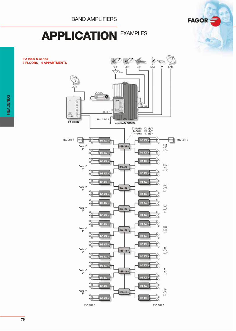
BAND AMPLIFIERS
APPLICATION EXAMPLES
MICROMATV FUTURA
BSD 201 S BSD 201 S
BSD 201 S
2150 MHz 105 dBμV862 MHz 102 dBμV47 MHz 97 dBμV
IFA 2000 N
BSD 201 S
DIS 409 +DIS 409 +
DIS 409 +DIS 409 +
DES 411 +
DIS 409 +DIS 409 +
DIS 409 +DIS 409 +
DIS 409 +DIS 409 +
DIS 409 +DIS 409 +
DES 416 +
DES 416 +
DIS 409 +DIS 409 +
DIS 409 +DIS 409 +
DES 420 +
DIS 409 +DIS 409 +
DIS 409 +DIS 409 +
DES 420 +
DIS 409 +DIS 409 +
DIS 409 +DIS 409 +
DES 420 +
DIS 409 +DIS 409 +
DIS 409 +DIS 409 +
DES 425 +
DIS 409 +DIS 409 +
DIS 409 +DIS 409 +
DES 425 +
IFA 2000 N series8 FLOORS - 4 APPARTMENTS
UHF
UCF 200
UHF UHF DAB FM SAT1
SAT2
ABF 012
CX 75 F
RF+ FI SAT 1
@ktive
58.665.262.6
56.264
61.8
59.367.866.1
56.566.365
53.864.964
5567.466.9
516565
5067.668.1
Planta Nº8º
Planta Nº7º
Planta Nº6º
Planta Nº5º
Planta Nº4º
Planta Nº3º
Planta Nº2º
Planta Nº1º
HE
AD
EN
DS
76
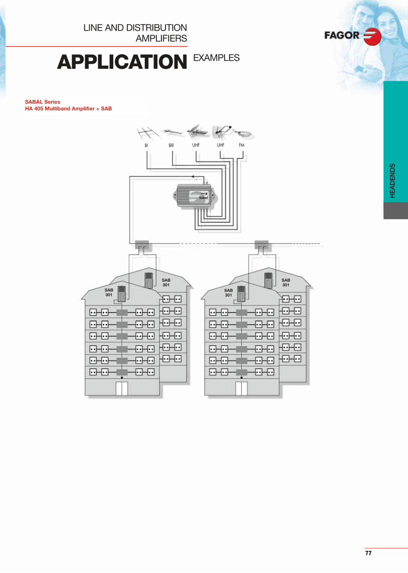
LINE AND DISTRIBUTION AMPLIFIERS
SABAL SeriesHA 405 Multiband Amplifier + SAB
SAB301
SAB301
SAB301
SAB301
BIII UHF UHF FMBI
APPLICATION EXAMPLES
HE
AD
EN
DS
77

LINE AND DISTRIBUTION AMPLIFIERS
HEADENDRF + 1ª FI SAT
WBA 433
WBA 433
WBA 433 WBA 433
WBA 433 WBA 433
UHF UHF SAT SAT SATFM
SABAL SeriesWBA 433 Wide Band Amplifier
APPLICATION EXAMPLES
HE
AD
EN
DS
78

HE
AD
EN
DS
79

80

81
whole range of products from simpleequipment for individual installations to
indoor amplification.
Mast band amplifiers
• AMB 600-N Series................................................... 82
• AMB 600-N (FM) Series .......................................... 83
• AMB 800 Series....................................................... 84
Power supply
• FA 802 N................................................................... 86
Examples.............................................................................. 87
Indoor amplifiers
• AD 52/AD 420 Series .............................................. 88
• AD 540 / AD 1000 Series ....................................... 89
• AD 2300 Series........................................................ 90
Examples.............................................................................. 91
Indoor amplifier
• MOD Series ............................................................. 92
A
INDEX Page
MA
ST
AN
D IN
DO
OR
A
MP
LIFI
ER
S
Mast and Indoor Amplifiers
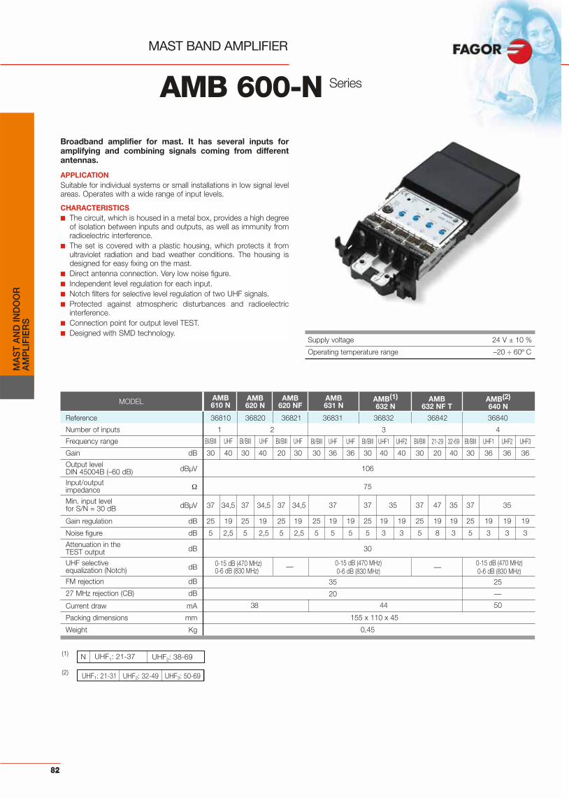
82
MA
ST
AN
D IN
DO
OR
A
MP
LIFI
ER
S
MAST BAND AMPLIFIER
AMB 600-N Series
Broadband amplifier for mast. It has several inputs foramplifying and combining signals coming from differentantennas.
APPLICATIONSuitable for individual systems or small installations in low signal levelareas. Operates with a wide range of input levels.
CHARACTERISTICS■ The circuit, which is housed in a metal box, provides a high degree
of isolation between inputs and outputs, as well as immunity fromradioelectric interference.
■ The set is covered with a plastic housing, which protects it fromultraviolet radiation and bad weather conditions. The housing isdesigned for easy fixing on the mast.
■ Direct antenna connection. Very low noise figure.■ Independent level regulation for each input.■ Notch filters for selective level regulation of two UHF signals.■ Protected against atmospheric disturbances and radioelectric
interference.■ Connection point for output level TEST.■ Designed with SMD technology.
Supply voltage 24 V ± 10 %
Operating temperature range –20 ÷ 60º C
(1)
(2)
MODEL AMB 610 N
AMB 620 N
AMB 620 NF
AMB 631 N
AMB(1) 632 N
AMB 632 NF T
AMB(2)640 N
N UHF1: 21-37 UHF2: 38-69
UHF1: 21-31 UHF2: 32-49 UHF3: 50-69
Reference 36810 36820 36821
Number of inputs 1 2
Frequency range BI/BIII UHF BI/BIII UHF BI/BIII UHF
Gain dB 30 40 30 40 20 30
Output level dBμVDIN 45004B (–60 dB)Input/outputimpedance
Min. input level dBμV 37 34,5 37 34,5 37 34,5for S/N = 30 dB
Gain regulation dB 25 19 25 19 25 19
Noise figure dB 5 2,5 5 2,5 5 2,5
Attenuation in the dBTEST outputUHF selective dB 0-15 dB (470 MHz) —equalization (Notch) 0-6 dB (830 MHz)FM rejection dB
27 MHz rejection (CB) dB
Current draw mA 38
Packing dimensions mm
Weight Kg
36831 36832 36842 36840
3 4
BI/BIII UHF UHF BI/BIII UHF1 UHF2 BI/BIII 21-29 32-69 BI/BIII UHF1 UHF2 UHF3
30 36 36 30 40 40 30 20 40 30 36 36 36
106
75
37 37 35 37 47 35 37 35
25 19 19 25 19 19 25 19 19 25 19 19 19
5 5 5 5 3 3 5 8 3 5 3 3 3
30
0-15 dB (470 MHz) — 0-15 dB (470 MHz) 0-6 dB (830 MHz) 0-6 dB (830 MHz)
35 25
20 —
44 50
155 x 110 x 45
0,45

83
MA
ST
AN
D IN
DO
OR
A
MP
LIFI
ER
S
MAST BAND AMPLIFIERFM PROCESSING
AMB 600-N Series
Broadband amplifier with FM processing . It has severalinputs for amplifying and combining signals coming fromdifferent antennas.
APPLICATIONSuitable for individual systems or small installations in low signal levelareas. Operates with a wide range of input levels.
CHARACTERISTICS■ The circuit, which is housed in a metal box, provides a high degree
of isolation between inputs and outputs, as well as immunity fromradioelectric interference.
■ The set is covered with a plastic housing, which protects it fromultraviolet radiation and bad weather conditions. The housing isdesigned for easy fixing on the mast.
■ Direct antenna connection. Very low noise figure.■ Independent level regulation for each input.■ Notch filters for selective level regulation of two UHF signals.■ Protected against atmospheric disturbances and radioelectric
interference.■ Connection point for output level TEST.■ Designed with SMD technology■ The AMB 624N, AMB 635N and AMB 644N models give higher
output level, keeping second and third order intermodulationproducts at very low level, when operate with strong input signals.
Supply voltage 24 V ± 10 %
Operating temperature range –20 ÷ 60º C
MODEL AMB 621 N
AMB 623 N
AMB 624 N
AMB 630 N
AMB 644 N
AMB(1) 634 N
AMB 635 N
Reference 36814 36823 36824
Number of inputs 2
Frequency range BI/FM/BIII UHF BI/FM/BIII UHF FM UHF
Gain dB -0,5 40 30 40 30 40
Output level dBμV 106 111DIN 45004B (–60 dB)Input/outputimpedance
Min. input level dBμV — 34,5 37 34,5 — 34,5for S/N = 30 dB
Gain regulation dB — 19 25 19 25 19
Noise figure dB — 2,5 5 2,5 5 2,5
Attenuation in the dBTEST output
UHF selective dB — —equalization (Notch)
27 MHz Rejection (CB) dB
Current drawn mA 38
Packing dimensions mm
Weight Kg
36830 36834 36845 36844
3 4
BI/FM/BIII UHF UHF BI/FM/BIII UHF 1 UHF 2 BI/FM BIII UHF BI/FM BIII UHF UHF
30 36 36 30 40 40 30 30 36 30 30 36 36
106 111
75
37 37 35 37 37
25 19 19 25 19 19 25 25 19 25 25 19 19
5 5 3 5 5
30
0-15 dB (470 MHz) — 0-15 dB (470 MHz) 0-6 dB (830 MHz) 0-6 dB (830 MHz)
20
44 50
155 x 110 x 45
0,45
(1) N UHF1: 21-37 UHF2: 38-69

84
MAST BAND AMPLIFIER
AMB 800
Professional mast band amplifiers, immune to all signalsfrom other services which share the radioelectricspectrum, such as mobile phones, wireless transmissions,terrestrial communications….
APPLICATIONSuitable for individual systems or small installations, with high sensiti-vity and output power (114 dBμV), the AMB 800 is a heavy-dutyamplifier, ideal for future applications according to new DigitalTerrestrial TV (DTT) requirements. It is prepared to process both ana-logue and digital signals during the migration towards DTT.
CHARACTERISTICS■ Very low noise figure and independent from gain regulation■ The mechanical solution guarantees an exceptional immunity
against noise invasion, a critical aspect for DTT reception.■ 3 Notch filters can be adjusted over the whole UHF band, or even in
their extremes to achieve an additional rejection to unwanted signals.■ F connectors.■ Output level Test.■ Wide range of input levels.■ AMB 802 DC, AMB 836 with DC pass for pre-amplifiers.
MODEL AMB 801 AMB 802 DC** AMB 810 AMB 820 AMB 823
Reference 36011 36012 36010 36020 36023Nbr. of inputs 1 2Bands UHF UHF BI/BIII UHF BI/BIII UHF BI÷FM/BIII UHFGain dB 38 28 28 38 28 38 28 38Gain regulation dB 15 15 25 15 25 15 25 15Output level DIN 45004B-60 dBμV 114Input/output impedance 75Noise figure dB 3 4 5 3 5 3 5 3Rejection out of band dB Compliance with EN 50083-2 “Antenna Input Resistance” • Internal immunity against unwanted signals from out of bandTest output dB –30 dB (from main output)Current draw mA 93Packing dimensions mm 170 x 105 x 50Weight Kg 0,355
MODEL AMB 824 AMB 830 AMB 831 AMB 832*
Reference 36024 36030 36031 36032Nbr. of inputs 2 3Bands FM BIII/UHF BI÷FM/BIII UHF UHF BI/BIII UHF UHF BI/BIII UHF1 UHF2
Gain dB 28 28/38 28 38 38 28 38 38 28 38 38Gain regulation dB 25 25/15 25 15 15 25 15 15 25 15 15Output level DIN 45004B-60 dBμV 114Input/output impedance 75Noise figure dB 5 3/5 5 6 6 5 6 6 5 3 3Rejection out of band dBCompliance with EN 50083-2 “Antenna Input Resistance” • Internal immunity against unwanted signals from out of bandTest output dB –30 dB (from main output)Current draw mA 100 93Packing dimensions mm 170 x 105 x 50Weight Kg 0,355
MA
ST
AN
D IN
DO
OR
A
MP
LIFI
ER
S
Series
Supply voltage 24 ± 10% VdcOperating temperature range – 20 ÷ 60º C
Selective equalization 3 tuneable UHF filters in main amplification lineNotch 1 390 MHz 12
660 MHz 7Notch 2 445 MHz 16
720 MHz dB 7Notch 3 600 MHz 4
975 MHz 11

85
UHF1: 21...37UHF1: 38...69* Other frequencies available under request.** With DC pass 12 Vcc, 40 mA
at UHF input.
B UHF1: 21-24 UHF2: 26-69T UHF1: 21-29 UHF2: 30-69
L UHF1: 21-34 UHF2: 35-69
N UHF1: 21-37 UHF2: 38-69
V UHF1: 21-39 UHF2: 41-69
A UHF1: 21-41 UHF2: 43-69
R UHF1: 21-45 UHF2: 46-69S UHF1: 21-47 UHF2: 48-69
Q UHF1: 21-49 UHF2: 50-69
W UHF1: 21-54 UHF2: 55-69
U UHF1: 21-56 UHF2: 57-69
C UHF1: 21-59 UHF2: 60-69
MODEL AMB 834* AMB 835 AMB 836** AMB 840*
Reference 36034 36035 36047 36055Nbr. of inputs 3 4Bands BI÷FM UHF1 UHF2 B BIII UHF FM BI÷DAB UHF BI÷FM/BIII UHF UHF1 UHF2
Gain dB 28 38 38 28 28 38 18 18 28 28 34 33 33Gain regulation dB 25 15 15 25 25 15 15 15 15 25 15 15 15Output level DIN 45004B-60 dBμV 114Input/output impedance 75Noise figure dB 5 3 3 5 5 3 6 6 4 5 6 7 7Rejection out of band dB Compliance with EN 50083-2 “Antenna Input Resistance” • Internal immunity against unwanted signals from out of bandTest output dB –30 dB (from main output)Current draw mA 93 70 100Packing dimensions mm 170 x 105 x 50Weight Kg 0,355
MA
ST
AN
D IN
DO
OR
A
MP
LIFI
ER
S
MAST BAND AMPLIFIER
AMB 800
Professional mast band amplifiers, immune to all signalsfrom other services which share the radioelectricspectrum, such as mobile phones, wireless transmissions,terrestrial communications….
APPLICATIONSuitable for individual systems or small installations, with high sensiti-vity and output power (114 dBμV), the AMB 800 is a heavy-dutyamplifier, ideal for future applications according to new DigitalTerrestrial TV (DTT) requirements. It is prepared to process both ana-logue and digital signals during the migration towards DTT.
CHARACTERISTICS■ Very low noise figure and independent from gain regulation■ The mechanical solution guarantees an exceptional immunity
against noise invasion, a critical aspect for DTT reception.■ 3 Notch filters can be adjusted over the whole UHF band, or even in
their extremes to achieve an additional rejection to unwanted signals.■ F connectors.■ Output level Test.■ Wide range of input levels.■ AMB 802 DC, AMB 836 with DC pass for pre-amplifiers.
Series
Supply voltage 24 ± 10% VdcOperating temperature range – 20 ÷ 60º C
Selective equalization 3 tuneable UHF filters in main amplification lineNotch 1 390 MHz 12
660 MHz 7Notch 2 445 MHz 16
720 MHz dB 7Notch 3 600 MHz 4
975 MHz 11
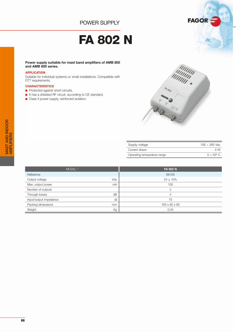
POWER SUPPLY
FA 802 N
Power supply suitable for mast band amplifiers of AMB 800and AMB 600 series.
APPLICATIONSuitable for individual systems or small installations. Compatible withDTT requirements.
CHARACTERISTICS■ Protected against short-circuits.■ It has a shielded RF circuit, according to CE standard.■ Class II power supply, reinforced isolation.
86
MA
ST
AN
D IN
DO
OR
A
MP
LIFI
ER
S
Supply voltage 195 ÷ 265 Vac
Current drawn 4 W
Operating temperature range 0 ÷ 50º C
MODEL * FA 802 N
Reference 66105
Output voltage Vdc 24 ± 10%
Max. output power mA 100
Number of outputs 2
Through losses dB 4
Input/output impedance 75
Packing dimensions mm 165 x 92 x 60
Weight Kg 0,45

INDIVIDUAL RECEPTION
220 VAC
TV
HI-FI
AMB 840
FA 802 N
BIV BVUHF FM
Mast amplification with AMB 836
AMB 840
24 VDC
APPLICATION EXAMPLES
220 VAC
TV
HI-FI
AMB 836
FA 802 N
UHF FM
Level meter
TEST
(-30 dB)24 VDC
87
@ktive
DAB
MA
ST
AN
D IN
DO
OR
A
MP
LIFI
ER
S
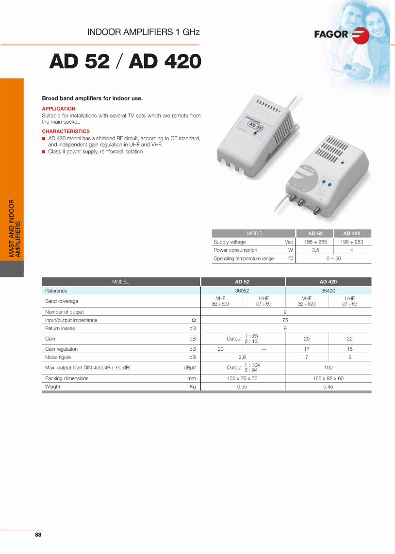
88
MA
ST
AN
D IN
DO
OR
A
MP
LIFI
ER
S
Broad band amplifiers for indoor use.
APPLICATIONSuitable for installations with several TV sets which are remote fromthe main socket.
CHARACTERISTICS■ AD 420 model has a shielded RF circuit, according to CE standard,
and independent gain regulation in UHF and VHF.■ Class II power supply, reinforced isolation.
INDOOR AMPLIFIERS 1 GHz
MODEL AD 52 AD 420
Supply voltage Vac 195 ÷ 265 198 ÷ 253
Power consumption W 3,5 4
Operating temperature range ºC 0 ÷ 50
AD 52 / AD 420
MODEL AD 52 AD 420
Reference 36052 36420
Band coverage VHF UHF VHF UHF(E2 ÷ S20) (21 ÷ 69) (E2 ÷ S20) (21 ÷ 69)
Number of output 2
Input/output impedance 75
Return losses dB 9
1 : 23Gain dB Output 2 : 13 20 22
Gain regulation dB 20 — 17 15
Noise figure dB 2,8 7 5
1 : 104Max. output level DIN 45004B (–60 dB) dBμV Output 2 : 94 100
Packing dimensions mm 135 x 70 x 70 165 x 92 x 60
Weight Kg 0,35 0,45

Self-powered broadband amplifier for indoor use.AD 540: amplifies signals from 47 to 862 MHz.AD 1000: amplifies signals from 47 to 862 MHz, and allowsreturn path (from 5 to 30 MHz).AD 1000 A: amplifies signals from 87 to 862 MHz.
APPLICATIONSuitable for individual digital terrestrial TV installations. The AD 1000and AD 1000 A models are compatible with CATVs operators.
CHARACTERISTICS■ Gain control■ It has slope regulation to compensate the losses due to coaxial
cable attenuation. Models AD 1000 and AD 1000A incorporate anequalization control.
■ AD 540: 4 independent outputs with the same output level.■ AD 1000/AD 1000 A: Two independent outputs, the second one
attenuated 10 dB with respect to the first one.■ The circuit is housed in a zamak box that ensures a high level of
shielding.
INDOOR AMPLIFIERFULL BAND 1 GHz
AD 540 /AD 1000
MODEL AD 540 AD 1000 AD 1000 A
Reference 36425 36100 36101
Number of inputs 1
Number of outputs 4 2
Frequency range 47 ÷ 862 87 ÷ 862
Gain dB 16 ÷ 20 (47 ÷ 862) Output 1: 20 / Output 2: 10
Max. output level DIN 45004B, –60 dBc dBμV 100 Output 1: 112 / Output 2: 102
Input / output return losses dB 10
Gain regulation dB 0 ÷ 16 0 ÷ 10
Tilt regulation dB – 0 ÷ 10
Noise figure dB 5 5
Input / output impedance 75
Return path frequency range MHz – 5 ÷ 30 5 ÷ 65
Return path through loss dB – 2,5
Input / output connectors F (f)
Packing dimensions mm 152 x 100 x 42 165 x 92 x 60
Weight Kg 0,4
MODEL AD 540 AD 1000
Supply voltage 230 Vac –15% +10%
Power consumption W 3 7
Operating temperature range ºC 0 ÷ 50
89
MA
ST
AN
D IN
DO
OR
A
MP
LIFI
ER
S

90
MA
ST
AN
D IN
DO
OR
A
MP
LIFI
ER
S
Supply voltage 230 Vac ± 10 %
Power consumption 5,5 VA
Operating temperature range 0 ÷ 50º C
Self-powered broadband amplifier for indoor use. Amplifiessignals of the following ranges: 47÷862 MHz and 950÷2300MHz. Includes return path.
APPLICATIONDesigned for amplification in digital or analogue terrestrial TV indoorinstallations.
CHARACTERISTICS■ Amplification with positive slope (more gain in high frequencies, 4 dB
in the RF band and 7 dB in the 1st IF SAT band) to compensate thecable attenuation.
■ 20 dB gain regulation in RF band.■ Two independent outputs, the second one attenuated 10 dB with
respect to the first one. ■ It allows DC pass between outputs and input. Includes return path,
DISEqC or 22 KHz.■ The circuit is housed in a zamak box that ensures a high level of
shielding.
INDOOR AMPLIFIER2,3 GHz
AD 2300
*950 ÷ 2300 MHz: IM3 at –35 dB47 ÷ 862 MHz: IM3 at –60 dB
MODEL AD 2300
Reference 36230
Number of inputs 1
Number of outputs 2
Frequency range MHz 47 ÷ 862 950 ÷ 2300
Gain 47 MHz 862 MHz 950 MHz 2150 MHz • Output 1
dB16 20 23 30
• Output 2 4 8 13 20Max. output level DIN 4500 4B*
• Output 1 dBμV 108 114• Output 2 96 104
Reflection coefficient dB 9 6
Gain regulation dB 20 —
Noise figure dB 4,5 10
Input / output impedance 75
Return path frequency range MHz 5 ÷ 30
Return path through loss dB 3,5 (Output 1)
Input / output connectors F (f)
Max. current drawn A 0,5
Packing dimensions mm 165 x 92 x 60
Weight Kg 0,4

INDOOR EQUIPMENT
Indoor amplification (RF & 1st IF SAT)
DES 4XX+
DES 4XX+
PAU
22+
BSD 203 BSD 210
1
2
DIS
409+
DIS
409+ AD 2300
AD 1000
+ VR
RF
21 69
21 69
AD 1000
APPLICATION EXAMPLES
Indoor amplification RF
Indoor amplification RF
AD 540
RF
BSD 201 S
91
MA
ST
AN
D IN
DO
OR
A
MP
LIFI
ER
S

MODEL MOD 500
Reference 86515
Output channel E2-E4 / E5-S20 / 21-69
Standard B /G / H / D / K / I / L / M / N
Output level dBμv 60 ÷ 75 (adjustable)
IN-OUT covered band MHz 2 -2150 MHz
IN-OUT insertion losses 15 - 47 MHz dB < 2,5
47-2150 MHz < 1,5
RF input/output impedance 75
RF input/output connectors F(f)
Video input level Vpp 0,9 ÷ 1
Video input impedance 75
Audio input level mV 150 ÷ 775
Adjustable audio deviation KHz ± 50
Audio input impedance k 10
Audio and Video input connectors RCA (f)
S/N ratio dB 55 dB
Packing dimensions mm 100 x 150 x 44
Weight kg 0,4
MOD Series
AUDIO/VIDEO MODULATOR
Self-powered modulator which generates an RF channel withthe Audio and Video information coming from a Video, DVD,IRD, video door entry system, security cameras, etc.
APPLICATIONSThis modulator enables the reception of a signal coming from a receiverwith Audio and Video output, on a TV set without Audio and Video input.The antenna signal from an outlet socket can be combined with anewly generated channel and both are delivered at the output, thusenabling their coaxial cable distribution throughout the dwelling.
CHARACTERISTICS■ Double side band modulation, allowing one channel spacing operation.■ Compact design, making it easy to install.■ The output channel is easily programmed by two buttons and an
alphanumerical display.■ Audio volume can be adjusted to be equalised with the volume of
other programmes.■ Incorporates a video-test bar generator making TV tuning easier.■ Multi-standard and multi-band, with one single model covering all
standards and channels.■ A PLL circuit ensures high stability of the output channel.
Supply voltage 230 Vac + 10 ÷ -15%
Power consumption 3 VA
Operating temperature range -10 ÷ +50º C
92
MA
ST
AN
D IN
DO
OR
A
MP
LIFI
ER
S

93
MA
ST
AN
D IN
DO
OR
A
MP
LIFI
ER
S

94

95
agor has designed a wide range of compo-nents for guaranteeing a perfect distribution
of the signal to each user.F
Tap-offs and Splitters
• Saddle & clamp DES-N / DIS-N Series................. 96
• F Connector SPT / TAP Series .............................. 97
Shielded diplexer
• DXR Series .............................................................. 99
Outlet sockets
• 5-1000 MHz BASIC Series ..................................... 100
• 5-2300 MHz BASIC Series ..................................... 101
Equalizers
• ECU Series .............................................................. 102
Coaxial cables
• CCF Series............................................................... 103
INDEX Page
DIS
TRIB
UTI
ON
Distribution

CONNECTIONS
TAP-OFFS AND SPLITTERSSADDLE CLAMP
96
DIS
TRIB
UTI
ON
WEATHERPROOF PROTECTOR
MODEL PE-DES N
Reference 85014Packing dimensions mm 380 x 160 x 160Weight Kg 1,1
Shielded tap-offs and splitters with saddle & clamp,suitable for QPSK, QAM, and analogue signal distribution incommunity installations.APPLICATIONAnalogue and Digital Terrestrial TV Installations, both individual orcommunity.
CHARACTERISTICS ■ Maximum efficiency with minimum output level at headend.■ Same level between users in the same floor.■ Linear attenuation in the whole band. ■ High signal levels can be used thanks to a special shielding design.■ Easy to set up.■ Weatherproof protector.■ Valid for reduced
space installations.■ Valid for DiseqC
signals
DES+ / DIS+ Series
DIS 204+ DIS 409+ DES 211+ DES 216+ DES 220+ DES 225+ DES 411+ DES 416+ DES 420+ DES 425+
85354 85355 85370 85371 85372 85373 85380 85381 85382 85383
2 4 2 4
5 ÷ 23003,5 7,5 2,5 1,2 0,7 0,5 4 1,8 0,9 0,63,5 7,5 2,2 1,1 0,8 0,5 3,5 1,8 0,9 0,64 7,5 2,4 1,1 0,8 0,6 4 1,9 0,9 0,7
4,5 8,5 2,9 1,5 1 1 4,2 2,8 1,4 1,15,5 9,5 3,2 1,5 1,2 1,4 4,4 3,2 1,9 1,65,5 9,5 3,7 2 1,5 1,8 4,5 3,5 2 1,7
11 16 21 25 11 15,5 20 2511 16 21 25 11 16 20 2511 16 21 25 11 16 20 2511 16 21,5 25 12 16 20 25
11,5 16,5 21,5 25 13 16 20 25,511,5 16,5 21,5 25,5 13 16,5 20,5 25,523 24 25 25 23 25 25 2520 21 25 25 23 25 25 25
24 24 21 22 22 25 21 21 22 2122 22 21 22 22 25 21 21 22 2314 14 17 20 20 22 15 16 20 2212 14 20 20 25 17 18 18 18 1913 12 20 20 25 22 20 22 23 2512 12 17 16 17 15 16 18 17 16
12 13 17 16 18 19 21 2012 12 12 12 16 16 16 16
NO NO SISI SI SI
NONONO
185 x 90 x 50
10
0,85
MODELS
Reference
Nr of outputs
Covered band MHz
5 - 47 MHz47 - 550 MHz
IN-OUT 550 - 862 MHzInsertion loss 950 - 1550 MHz dB
1550 - 2150 MHz2150 - 2300 MHz
5 - 47 MHz47 - 550 MHz
IN-TAP 950 - 1550 MHzTap loss 950 - 1550 MHz dB
1550 - 2150 MHz2150 - 2300 MHz
Isolation 47 - 950 MHz dBOUT-TAP 950 - 2150 MHzOUT-OUT 47 - 862 MHz dBTAP-TAP isolation 950 - 2150 MHzIN 47 - 862 MHz dBReturn loss 950 - 2150 MHzOUT 47 - 862 MHz dBReturn loss 950 - 2150 MHzTAP 47 - 862 MHz dBReturn loss 950 - 2150 MHzCD pass IN - OUT24 VDC, 0, 5A, 22 KHz OUT - IN
CD pass IN - TAP24 VDC, 0, 5A, 22 KHz TAP - IN
TAP-TAP
Packing dimensions mm
Units per packing
Weight Kg
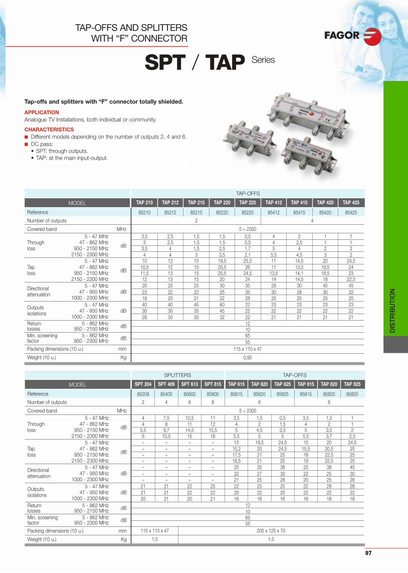
DIS
TRIB
UTI
ON
97
Tap-offs and splitters with “F” connector totally shielded.
APPLICATIONAnalogue TV Installations, both individual or community.
CHARACTERISTICS■ Different models depending on the number of outputs 2, 4 and 6.■ DC pass:
• SPT: through outputs.• TAP: at the main input-output.
TAP-OFFS AND SPLITTERS WITH “F” CONNECTOR
SPT / TAP Series
SPT 204 SPT 409 SPT 613 SPT 815 TAP 615 TAP 620 TAP 625 TAP 815 TAP 820 TAP 825
85209 85405 85600 85800 85615 85620 85625 85815 85820 85825
2 4 6 8 6 8
5 ÷ 23004 7,5 10,5 11 3,5 1,5 0,5 3,5 1,5 14 8 11 12 4 2 1,5 4 2 1
5,5 9,7 14,5 15,5 5 4,5 3,5 5 3,5 26 10,5 15 16 5,5 5 5 5,5 3,7 2,5– – – – 15 19,5 24,5 15 20 24,5– – – – 15,2 20 24,5 15,5 20,5 25– – – – 17,5 21 25 18 22,5 25– – – – 18,5 21 25 19 22,5 25– – – – 25 35 38 25 38 45– – – – 22 27 30 22 25 30– – – – 21 25 28 20 25 28
21 21 22 25 22 25 25 22 28 2821 21 22 22 20 22 20 22 22 2220 21 20 21 16 16 16 16 18 18
12106555
115 x 110 x 47 205 x 125 x 70
1,5 1,5
MODÈL
Reference
Number of outputs
Covered band MHz5 - 47 MHz
Through 47 - 862 MHzdBloss 950 - 2150 MHz
2150 - 2300 MHz5 - 47 MHz
Tap 47 - 862 MHzdBloss 950 - 2150 MHz
2150 - 2300 MHz
Directional 5 - 47 MHz
attenuation 47 - 950 MHz dB1000 - 2300 MHz
Outputs 5 - 47 MHz
isolations 47 - 950 MHz dB1000 - 2300 MHz
Return 5 - 862 MHz dBlosses 950 - 2150 MHzMin. screening 5 - 862 MHz dBfactor 950 - 2300 MHz
Packing dimensions (10 u.) mm
Weight (10 u.) Kg
SPLITTERS TAP-OFFS
TAP 210 TAP 212 TAP 215 TAP 220 TAP 225 TAP 412 TAP 415 TAP 420 TAP 425
85210 85212 85215 85220 85225 85412 85415 85420 85425
2 4
5 ÷ 23003,5 2,5 1,5 1,5 0,5 4 2 1 13 2,5 1,5 1,5 0,5 4 2,5 1 1
3,5 4 1,5 2,5 1,7 5 4 2 24 4 3 3,5 2,1 5,5 4,5 3 2
10 12 15 19,5 25,5 11 14,5 20 24,510,5 12 15 20,5 26 11 13,5 19,5 2411,5 13 15 20,5 24,5 13,5 14,1 18,5 2312 13 15 20 24 14 14,5 18 22,520 25 25 30 35 28 30 45 4523 22 22 25 35 30 28 30 3218 20 21 22 28 25 25 25 2540 40 45 60 22 23 23 23 2330 30 35 45 22 22 22 22 2228 30 30 32 22 21 21 21 21
12106555
115 x 110 x 47
0,95
MODEL
Reference
Number of outputs
Covered band MHz5 - 47 MHz
Through 47 - 862 MHzdBloss 950 - 2150 MHz
2150 - 2300 MHz5 - 47 MHz
Tap 47 - 862 MHzdBloss 950 - 2150 MHz
2150 - 2300 MHz
Directional 5 - 47 MHz
attenuation 47 - 950 MHz dB1000 - 2300 MHz
Outputs 5 - 47 MHz
isolations 47 - 950 MHz dB1000 - 2300 MHz
Return 5 - 862 MHz dBlosses 950 - 2150 MHzMin. screening 5 - 862 MHz dBfactor 950 - 2300 MHz
Packing dimensions (10 u.) mm
Weight (10 u.) Kg
TAP-OFFS

PAU 24 FPAU 24 F
BSD 201 S BSD 201 S
UHF
UCF 200
UHF UHF DAB FM SAT1
SAT2
ABN 012F
CX 75 F
RF+ FI SAT 1RF+ FI SAT 2IFA 2000 N
PAU 24 FPAU 24 F
PAU 24 FPAU 24 F
PAU 24 FPAU 24 F
TAP 215
TAP 215
TAP 215
TAP 215
TAP 212
TAP 212
TAP 212
TAP 212
DIS
TRIB
UTI
ON
98
RISER DISTRIBUTIONNETWORK
FLOOR DISTRIBUTION NETWORK
FLOOR DISTRIBUTION NETWORK
APPLICATION EXAMPLES
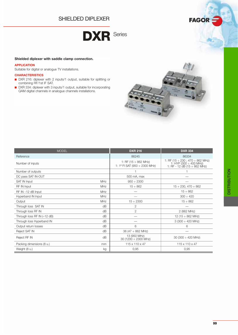
Shielded diplexer with saddle clamp connection.
APPLICATIONSuitable for digital or analogue TV installations.
CHARACTERISTICS■ DXR 216: diplexer with 2 inputs/1 output, suitable for splitting or
combining RF/1st IF SAT.■ DXR 334: diplexer with 3 inputs/1 output, suitable for incorporating
QAM digital channels in analogue channels installations.
SHIELDED DIPLEXER
DXR Series
MODEL DXR 216 DXR 334
Reference 86245 86334
1: RF (15 ÷ 862 MHz) 1: RF (15 ÷ 230 ; 470 ÷ 862 MHz)Number of inputs 1: HYP (300 ÷ 400 MHz)
1: 1ª FI SAT (950 ÷ 2300 MHz) 1: RF - 12 dB (15 ÷ 862 MHz)
Number of outputs 1 1
DC pass SAT IN-OUT 500 mA, max —
SAT IN Input MHz 950 ÷ 2300 —
RF IN Input MHz 15 ÷ 862 15 ÷ 230, 470 ÷ 862
RF IN –12 dB Input MHz — 15 ÷ 862
Hyperband IN Input MHz — 300 ÷ 420
Output MHz 15 ÷ 2300 15 ÷ 862
Through loss SAT IN dB 2 —
Through loss RF IN dB 2 2 (862 MHz)
Through loss RF IN (–12 dB) dB — 12 (15 ÷ 862 MHz)
Through loss Hyperband IN dB — 3 (300 ÷ 420 MHz)
Output return losses dB 6 6
Reject SAT IN dB 36 (47 ÷ 862 MHz) —
13 (950 MHz) 30 (300 ÷ 420 MHz)Reject RF IN dB 30 (1200 ÷ 2300 MHz)
Packing dimensions (8 u.) mm 115 x 110 x 47 115 x 110 x 47
Weight (8 u.) kg 0,95 0,95
DIS
TRIB
UTI
ON
99

DIS
TRIB
UTI
ON
100
Outlet sockets with inductive devices for adequate filtering ofthe signals at the outputs, with minimum through losses.
APPLICATIONTV Installations, both individual or community to be used as endsocket or for cascading.
CHARACTERISTICS■ The circuit has a metal (zamak) housing to achieve a high degree of
shielding.■ It has a special shielding at the input and output connections, and
it is designed for easy installation.■ The outlet’s directivity guarantees enough isolation between floors.■ Compatible with most of the electrical devices available.
OUTLET SOCKETS5 ÷ 1000 MHz
BASIC Series
*BIF 01 S model must be connected directly to tap-off or splitter.
TV - SAT COVER
MODEL
Reference
Technology
Band coverage MHz
Return path 5 - 68 MHzThrough losses 68 - 470 MHz dB
470 - 1000 MHz
Return path 5 - 68 MHz
Derivation losses TV 118 - 470 MHz dB470 - 1000 MHzR 87,5 - 108 MHz
Directivity TV - OUT dBR - OUT
Isolation TV - R dB
Shielding factor 40 - 470 MHz dB70 - 862 MHz
Impedance
Return losses dB
Output connectors (UNE 20-523-79) RTV
Packing dimensions (20 u.) mm
Weight (20 u.) Kg
BIF 01 S BIF 01 N BIF 05 N BIF 09 N BIF 14 N BRF 00 N
85164 85159 85160 85161 85162 85163
Inductive Resistive
5 ÷ 1000
2,5 1,5 1,2 4Single* End 2,5 1 1,2 4
2,5 1 1,6 4
0,5 2,5 7,5 11 13,5 40,5 3 7 11 15 40,5 3 7 11 15,2 46 6 12,5 18 17 15
— — 15 —— — 30 —
30 —
7565
75 —
9,5 —
IEC 9,5 (f) IEC 9,5 (m)
300 x 165 x 85
1,5
MODEL C BIF C BIF B
Reference 85033 85034
Colour beige white
Packing dimensions (20 u.) mm 190 x 90 x 85
Weight (20 u.) Kg 0,5
SUPPLEMENT FOR SURFACE MOUNTING
MODEL SS BT SS BT B
Reference 85020 85031
Colour beige white
Packing dimensions (15 u.) mm 260 x 135 x 90
Weight (15 u.) Kg 0,5
Frequency (MHz) 5 68 87,5 108 118 1000
TV
RADIO

DIS
TRIB
UTI
ON
101
Outlet sockets with inductive devices for adequate filtering ofthe signals at the outputs, with minimum through losses.
APPLICATIONSuitable for Digital TV, up to 2300 MHz in individual and communityinstallations.
CHARACTERISTICS■ The circuit has a metal (zamak) housing to achieve a high degree of
shielding.■ It has a special shielding at the input and output connections, and
it is designed for easy installation.■ The outlet’s directivity guarantees enough isolation between floors.■ Compatible with most of the electrical devices available.
OUTLET SOCKETS5 ÷ 2300 MHz
BASIC Series
Frequency (MHz) 5 862 950 2300
TV
SAT
TV - SAT COVER
MODEL C BSD C BSD B
Reference 86230 86231
Colour beige white
Packing dimensions (20 u.) mm 190 x 90 x 85Weight (20 u.) Kg 0,5
SUPPLEMENT FOR SURFACE MOUNTING
MODEL SS BT SS BT B
Reference 85020 85031
Colour beige white
Packing dimensions (15 u.) mm 260 x 135 x 90
Weight (15 u.) Kg 0,5
*BSD 201 S and BSD 201 SDC model must be connected directly to tap-offs or splitter.
MODEL
Reference
Number of outputs
Band coverage MHz
DC passIN-OUT 300 mA max
SAT 300 mA max5 - 30 MHz
Through losses47 - 862 MHz
dB950 - 2150 MHz2150 - 2300 MHz
5 - 30 MHz
Derivation losses47 - 862 MHz
dB950 - 2150 MHz2150 - 2300 MHz
5 - 30 MHz
Directivity47 - 862 MHz
dB950 - 2150 MHz2150 - 2300 MHz
5 - 30 MHz
Isolation TV-R47 - 862 MHz
dB950 - 2150 MHz2150 - 2300 MHz
Return losses5 - 862 MHz
dB950 - 2300 MHzVHF 30 - 300 MHz dBShielding factor UHF 300 - 862 MHzSAT 950 - 2300 MHz
Output connectors (UNE 20-523-79) TVSAT
Packing dimensions (20 u.) mm
Weight (20 u.) Kg
BSD 201 S BSD 201 SDC BSD 203 N BSD 203 DC BSD 210 N BSD 210 DC BSD 215 N BSD 220 N
86218 86221 86205 86204 86219 86211 86215 86220
2
5 ÷ 2300
— — — — yes — yes — yes — yes — —
— 3,0 3,0 3,0
Single*— 2,5 2,0 1,8— 2,5 3,0 3,0— 3,0 3,0 3,0
0,5 2,0 10 15,0 16,01 3,0 11,5 15,0 20,01 3,0 12 16,0 20,01 3,0 12,5 16,0 22,0— — 15 23 25— — 22 23 25— — 18 20 25— — 20 20 2330 30 30 25 3515 15 25 25 3015 15 15 15 2518 18 25 20 30
106
756555
IEC 9,5 (f)IEC 9,5 (m)
300 x 165 x 85
2
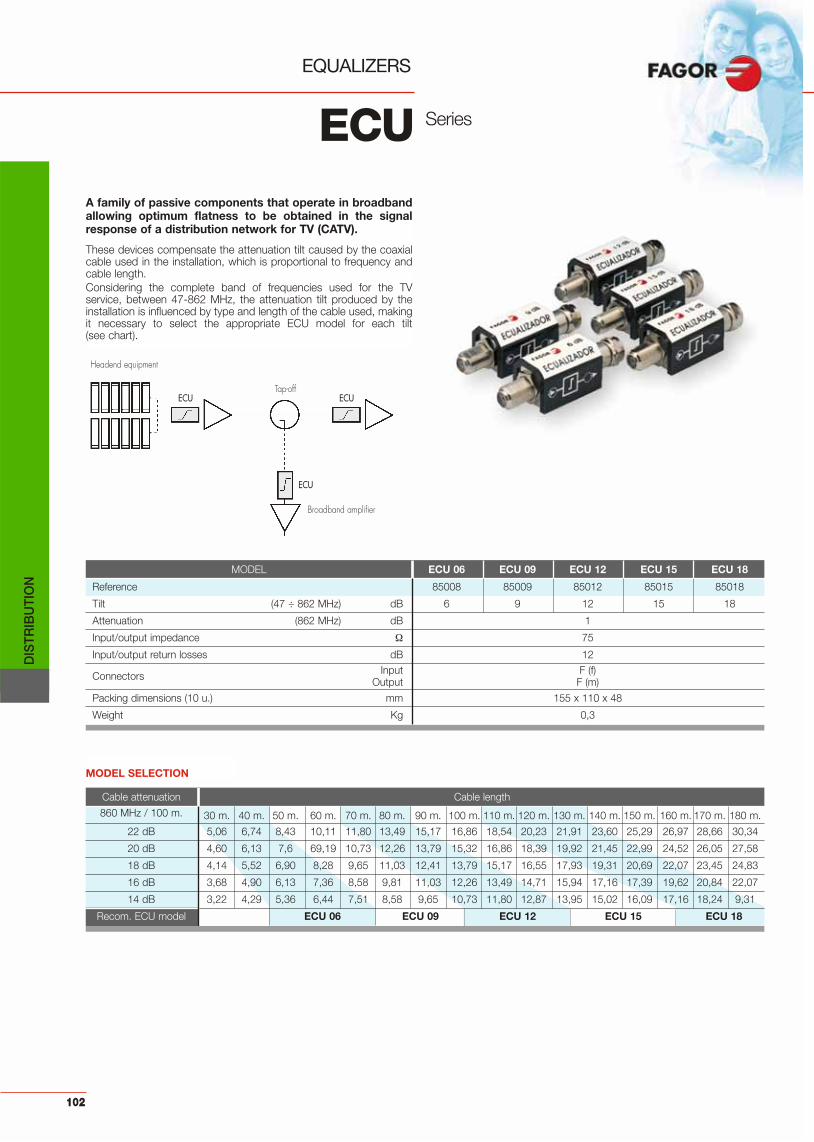
DIS
TRIB
UTI
ON
102
A family of passive components that operate in broadbandallowing optimum flatness to be obtained in the signalresponse of a distribution network for TV (CATV).
These devices compensate the attenuation tilt caused by the coaxialcable used in the installation, which is proportional to frequency andcable length.Considering the complete band of frequencies used for the TVservice, between 47-862 MHz, the attenuation tilt produced by theinstallation is influenced by type and length of the cable used, makingit necessary to select the appropriate ECU model for each tilt(see chart).
EQUALIZERS
ECU Series
MODEL ECU 06 ECU 09 ECU 12 ECU 15 ECU 18
Reference 85008 85009 85012 85015 85018
Tilt (47 ÷ 862 MHz) dB 6 9 12 15 18
Attenuation (862 MHz) dB 1
Input/output impedance 75
Input/output return losses dB 12Input F (f)Connectors Output F (m)
Packing dimensions (10 u.) mm 155 x 110 x 48
Weight Kg 0,3
MODEL SELECTION
Cable attenuation Cable length
860 MHz / 100 m. 30 m. 40 m. 50 m. 60 m. 70 m. 80 m. 90 m. 100 m. 110 m. 120 m. 130 m. 140 m. 150 m. 160 m. 170 m. 180 m.
22 dB 5,06 6,74 8,43 10,11 11,80 13,49 15,17 16,86 18,54 20,23 21,91 23,60 25,29 26,97 28,66 30,34
20 dB 4,60 6,13 7,6 69,19 10,73 12,26 13,79 15,32 16,86 18,39 19,92 21,45 22,99 24,52 26,05 27,58
18 dB 4,14 5,52 6,90 8,28 9,65 11,03 12,41 13,79 15,17 16,55 17,93 19,31 20,69 22,07 23,45 24,83
16 dB 3,68 4,90 6,13 7,36 8,58 9,81 11,03 12,26 13,49 14,71 15,94 17,16 17,39 19,62 20,84 22,07
14 dB 3,22 4,29 5,36 6,44 7,51 8,58 9,65 10,73 11,80 12,87 13,95 15,02 16,09 17,16 18,24 9,31
Recom. ECU model ECU 06 ECU 09 ECU 12 ECU 15 ECU 18
Headend equipment
Broadband amplifier
Tap-offECU ECU
ECU

Low loss cables for use in CATV signal distribution in com-munity and individual MATV-SMATV installations.
APPLICATION• CCF SAT is valid for 1st IF SAT installations.• CCF 017 & CCF 020 is used in general distribution.• CCF SAT H in a low smoke halogen free cable(LSHF). • CCF TRA & CCF TRN:are valid for trunk installations.
CHARACTERISTICS■ Black cables should be used for distribution
where PE cables are to be exposed to sunlight.
COAXIAL CABLES
CCF Serie
CCF TRA
CCF SAT-N
CCF SAT
MODEL CCF TRN CCF TRA CCF SAT CCF SAT CCF SAT N CCF SAT H CCF SAT H CCF 019 CCF 019 CCF 019 N CCF 017 CCF 020
Reference 84121 84111 84102 84123 84104 84112 84133 84119 84019 84020 84127 84129
Coil length 250 250 250 100/500 250 250 100/500 100/500 250 250 100/500 100/500
Coil support wood wood cardboard cardboard cardboard plastic cardboard cardboard cardboard cardboard cardboard cardboard
External conductor PE black PE black PVC white PVC white PE black LSFH white LSFH white PVC white PVC white PE black PVC white PVC white
Packing dimensions 400 x 400 x 380 360 x 360 x 350 360 x 360 x 180 270 x 270 x 660 360 x 360 x 180 265 x 265 x 300 270 x 270 x 660 270 x 270 x 660 360 x 360 x 180 360 x 360 x 180 270 x 270 x 660 270 x 270 x 660
Weight 26,8 25,5 12 5/25 10 10,5 5,5/28 5/25 12 10 4,5/23 4,5/23
MODEL CCF TRN CCF TRA CCF SAT CCF SAT H CCF 019 CCF 017 CCF 020CCF SAT N CCF 019 N
Internal conductorMaterial CuDiameter mm 1,6 1,63 1,1 1,1 1 1,15 1Resistance Ω/Km 8,57 9 20 19 23 20 22DielectricMaterial PE physical process dielectricDiameter mm 7,2 7,2 4,8 4,8 4,8 4,9 4,6External conductorMaterial sheet Cu / Pet Al / Pet / Al Cu / Pet Al / Pet / AlMaterial net Cu CuSn Cu AlResistance Ω/Km 8,3 8 22 21 30 33 46External conductorDiameter mm 10,2 10,1 6,7 6,8 6,8 6,9 6,6Min. curvature radius mm 80 40Attenuation / 100 m: 50 MHz 2,7 3,1 4,8 4,4 4,7 4,8 4,5
100 MHz 3,8 4,4 6,5 6,2 6,5 6,4 6,6200 MHz 5,4 6,3 8,6 8,7 8,8 8,5 8,6300 MHz 6,6 7,7 10 10,7 10,3 9,8 10,2470 MHz 8,3 9,6 12,5 13,4 12,8 12,3 12,7600 MHz 10,2 10,8 14,9 15,1 14,9 14,5 15,1860 MHz dB 12,3 13 17,9 18,1 17,8 17,4 18,1
1000 MHz 13,5 14 22,2 19,5 20 22,3 19,41350 MHz 16,4 16,2 22,4 22,7 21,6 22,2 211500 MHz 17,3 17,1 23,5 23,9 22,6 23,3 24,41750 MHz 18,7 18,5 25,7 25,8 26,4 25,8 26,42050 MHz 18,9 20 27,6 27,9 29,5 28,2 29,32150 MHz 19,8 20,5 28,9 28,6 30,9 29,6 30,7
Shielding efficiency 5-1000 MHz dB 90 80 75 701000-2150 MHz 85 75 70 65
Capacity pF/m 54 55Impedance Ω 75Reflection point dB < –20
DIS
TRIB
UTI
ON
103

104

105
AC
CE
SS
OR
IES
Accessories
whole range of accessories to improve thequality of the installations, such as combiners,
attenuators, filters, ...A

AC
CE
SS
OR
IES TYPE OF CONNECTOR MOD. REF.
IEC (f)-IEC (m) AT 323 85005
IEC (f)-IEC (m) AT 020 85007
TYPE OF CONNECTOR MOD. REF.
F(f)-F(m) ICF 001 85051
SUPPLY INJECTORFrequency band: 5 to 2150 MHzReturn losses: -10 dB Through losses: 0,5 dBDC pass: 1A
106
TYPE OF CONNECTOR MOD. REF.
F (m)-F (f) FAT 010 85041
FIX ATTENUATORFrequency band: 5 to 2300 MHzLosses: 10 dBReturn losses: 10 dBImpedance: 75 Ohm.DC block
ADJUSTABLE ATTENUATORFrequency band: 47 ÷ 862 MHzAT 323: Regulation margin: 3 - 23 dBAT 020: Impedance: 75 Ohm.
Regulation margin: 0 - 23 dB
ACCESSORIES
TYPE OF CONNECTOR MOD. REF.
F(f)-F(m) ATF 020 85050
ADJUSTABLE ATTENUATORFrequency band: 5 to 2150 MHzReturn losses: -10 dB Through losses: 0,5 to 20 dBDC pass (0-22 KHz): 1A
AT 323 AT 020
TWO WAY SPLITTER COMBINER
TWO WAY SPLITTER COMBINER
Band coverage: 5 ÷ 862 MHzImpedance: 75 Combining losses: 4 dBOutput isolation: 22 dB
Band coverage: 5 ÷ 862 MHzImpedance: 75 Combining losses: 4 dBOutput isolation: 22 dB
TYPE OF CONNECTOR MODEL REF.
2 x IEC (f) - 1 x IEC (m) MB 021 85001
TYPE OF CONNECTOR MODEL REF.
2 x IEC (m) - 1 x IEC (f) DB 012 85002
TWO WAY SPLITTER COMBINERBand coverage: 5 ÷ 862 MHzImpedance: 75 Combining losses: 4 dBOutput isolation: 22 dB
TYPE OF CONNECTOR MODEL REF.
F (f) MD 012F 85028

AC
CE
SS
OR
IES
TYPE OF CONNECTOR MODEL REF.
F(f)-F(m) FTF 245 85052
DOUBLE TRAP FILTERFrequency band: 470 to 862 MHzIn band return losses (out of notch filter): >10 dBRejection at central frequency (Fc): 18 dB at470 MHz / 10 dB at 862 MHzRejection at Fc ± 12 MHz: 2 dBIn band through losses: <1 dBDC pass: 1 A
107
TYPE OF CONNECTOR MODEL REF.
— RC 075 85010
LOADING RESISTOR75 resistor suitable for loading unusedinputs/outputs.
TYPE OF CONNECTOR MODEL REF.
F (f)-F (m) FT 110 F 85030
TRAP FILTER (BI)
TYPE OF CONNECTOR MODEL REF.
F(f)-F(m) FT 130 F 85023
TRAP FILTER (BIII)Insertion losses: <1 dBAttenuation: 20 dBOutband attenuation: 1 dBSelectivity: 2 dB (±12 MHz)Thermal drift: 20 KHz / ºC
Insertion losses: <1 dBAttenuation: 20 dBSelectivity: 2 dB (±12 MHz)Thermal drift: 20 KHz / ºC
TYPE OF CONNECTOR MODEL REF.
F (m) CX 75 F 84011
75 F LOADCoaxial resistive load for loading openconnectors.(SCM 5000, 6000 and 7000 series).
TYPE OF CONNECTOR MODEL REF.
F (m)-F (f) FPA 470 85042
HIGH PASS FILTERPassage band: 470 to 1000 MHzInsertion losses: 1,5 dBReturn losses: 10 dBImpedance: 75 Ohm.
ACCESSORIES
BROAD BAND AMPLIFIER (UHF)Frequency band: 470 ÷ 862 MHzGain: 12 dBFlatness: 2 dBNoise figure: 3,5 dBPower supply: 24 V ± 5%Consumption: <50 mAOutput level:
• ABF 012: 98 dBμV• AB 012 T: 105 dBμV
AB 012 T: telepowered
TYPE OF CONNECTOR MODEL REF.
F(f)-F(m) ABF 012 85053
F(f)-F(m) AB 012 T 85025

AC
CE
SS
OR
IES
“F” ADAPTORFemale-female F adapter (5 ÷ 2300 MHz).
TYPE OF CONNECTOR MODEL REF.
CCF 017-N CNR MF 84012
TYPE OF CABLE MODEL REF.
CCF TRN / CCF TRA CNR F TRN 84014
TYPE OF CONNECTOR MODEL REF.
F(f)-F(f) ADF HHS 84016
F (m) CONNECTORF(m) connector for cable (outside diameter 6,8 mm).
108
TYPE OF CONNECTOR MODEL REF.
IEC 9,5 (m) CNR MI 84028
IEC 9,5 (f) CNR HI 84029
SHIELDED CONNECTOR
CONNECTORF(m) connector for trunk cable.
ACCESSORIES
75 F-F COAXIAL BRIDGERigid 75 coaxial bridge for splitting or combining RF signals.Raster: 48 mm. (Ref. 84031 y 84003)
Multi-processing systemRaster: 40 mm. (Ref. 84034)
Nexum system
TYPE OF CONNECTOR MODEL REF.
F (m) - F (m) PMD FF 84031
F (m) - F (m) PMD FFN 84034
PMD FF PMD FF N

AC
CE
SS
OR
IES
109

110

111
Technical Notes
Technical Notes ................................................................. 112
INDEX Page
TEC
HN
ICA
LN
OTE
S

112
TECHNICAL NOTES
TEC
HN
ICA
LN
OTE
S
CHANNEL DEFINITION
CHANNEL PICTURE AUDIOTV BAND CHANNEL LIMITS CARRIER CARRIER
MHz MHz MHz
Standard B Italy
BI A 52,5 - 59,5 53,75 59,25B 61 - 68 62,25 67,75
B (II) C 81 - 88 82,25 87,75B (III) D 174 - 181 175,25 180,75
E 182,5 - 189,5 183,75 189,25F 191 - 198 192,25 197,75G 200 - 207 201,25 206,75H 209 - 216 210,25 215,75H1 216 - 223 217,25 222,75H2 223 - 230 224,25 229,75
Standard D OIRT
BI I 48,5 - 56,5 49,75 56,25II 58 - 66 59,25 65,75III 76 - 84 77,25 83,75
B (II) IV 84 - 92 85,25 91,75V 92 - 100 93,25 99,75
BIII VI 174 - 182 175,25 181,75VI 182 - 190 183,25 189,75VIII 190 - 198 191,25 197,75IX 198 - 206 199,25 205,75X 206 - 214 207,25 213,75XI 214 - 222 215,25 221,75XII 222 - 230 223,25 229,75
Standard I Ireland
BI A 44,5 - 52,5 45,75 51,75B 52,5 - 60,5 53,75 59,75C 60,5 - 68,5 61,75 67,75
BIII D 174 - 182 175,25 181,25E 182 - 190 183,25 189,25F 190 - 198 191,25 197,25G 198 - 206 199,25 205,25H 206 - 214 207,25 213,25I 214 - 222 215,25 221,25J 222 - 230 223,25 229,2
Standard L France
BI 2 49,00 - 57,00 49,25 55,753 53,75 - 61,75 54,00 60,504 57,00 - 65,00 57,25 63,75
BIII 5 174,75 - 182,75 176,00 182,506 182,75 - 190,75 184,00 190,507 190,75 - 198,75 192,00 198,508 198,75 - 206,75 200,00 206,509 206,75 - 214,75 208,00 214,5010 214,75 - 222,75 216,00 222,50
Pv
Ps 1
Ps 2Sc
16 dB
10 ÷ 13 dB
7 dB
4,43 MHz
5,5 MHz
7 MHz
0,25 MHz0,75 MHz
5,74 MHz
Pv
Ps 1
Ps 2Sc
16 dB
10 ÷ 13 dB
7 dB
4,43 MHz
5,5 MHz 1,25 MHz1,25 MHz
5,74 MHz
8 MHz
Pv
Ps
Sc
16 dB
7 dB
4,43 MHz
6 MHz 0,75 MHz1,25 MHz
8 MHz
STANDARD B
STANDARD G
STANDARD IPv
Ps
Sc
16 dB
10 dB
4,43 MHz
6,5 MHz 0,25 MHz1,25 MHz
8 MHz
STANDARD L

113
TECHNICAL NOTES
CCIR STANDARDS
CCIR-Standard B D G H I K L M N
Number of lines 625 625 625 625 625 625 625 525 625
Channel Bandwidth 7 8 8 8 8 8 8 6 6
Video Bandwidth (MHz) 5 6 5 5 5,5 6 6 4,2 4,2
Video sound spacing +5,5 +6,5 +5,5 +5,5 +6 +6,5 +6,5 +4,5 +4,5
Vestigial side band (MHz) 0,75 0,75 1,25 1,25 1,25 0,75 1,25 0,75 0,75
Picture modulation Neg. Neg. Neg. Neg. Neg. Neg. Pos. Neg. Neg.
Sound modulation FM FM FM FM FM FM AM FM FM
COUNTRY VHF UHF TV STANDARD
Algeria B H PALArgentina N N PAL-NAustralia B H PALAustria B G PALBahrein B G PALBelgium B H PALBulgary D K SECAMChina D K PALCyprus B G PAL/SECAMCzech Rep. D K SECAMDenmark B G PALEgypt B G; H SECAMFinland B G PALFrance L L SECAMGermany B G PALGibraltar B G PALGreat Britain I I PALGreece B G SECAMHolland B G PALHong Kong I I PALHungary D K SECAMIceland B G PALIndia B — PALIndonesia B — PALIrak B — SECAMIran B G SECAMIreland I I PALIsrael B G PALItaly B G PALJapan M M NTSCJordan B G PALKorea M — NTSCKuwait B G PALLebanon B — SECAMLibya B H SECAMLuxembourg B/L G/L SECAM/PALMalaysia B G PAL
COUNTRY VHF UHF TV STANDARD
Malta B H PALMexico M M NTSCMonaco E L/G SECAM/PALMorocco B H SECAMNigeria B G PALNorway B G PALOman B G PALPakistan B G PALPhilippines M M NTSCPoland D K SECAMPortugal B G PALQuatar B G PALRomania D K PALSaudi Arabia B G PAL/SECAMSingapore B G PALSouthafrica I I PALSpain B G PALSri Lanka B — PALSweden B G PALSwitzerland B G PALSyria B — SECAMThailand B/M — PALTunisia B G SECAMTurkey B G PALU.A.E. B G PALU.S.A. M M NTSCYemen B — PALYugoslavia B G PAL
CCIR = Comité Consultatif International des RadiocommunicationsPAL = Phase Alternation LineSECAM = Séquentielle à mémoireNTSC = National Television System Commitee
TEC
HN
ICA
LN
OTE
S

114
TECHNICAL NOTES
TEC
HN
ICA
LN
OTE
S
FREQUENCY ALLOCATIONS
BI FM S Low BIII S High Hyperband BIV BV
E2-E4
S1-S10 E5-E12 S11-S21 S21-S41 E21-E37 E38-E69
47 68 87,5 108 174 230 300 470 606 862 MHz
VHF UHF
CHANNELS ACCORDING TO CCIR, B, G, I (EUROPE) STANDARDS
CHANNEL VIDEO AUDIO FREC.CHANNEL BANDWIDTH (B) (B) CENTRAL
MHz MHz MHz MHzVHF BI 2 47...54 48,25 53,75 50,5
3 54...61 55,25 60,75 57,54 61...68 62,25 67,75 64,5
VHF Bs(low) S1 104...111 105,25 110,75 107,5
S2 111...118 112,25 117,75 114,5S3 118...125 119,25 124,75 121,5S4 125...132 126,25 131,75 128,5S5 132...139 133,25 138,75 135,5S6 139...146 140,25 145,75 149,5S7 146...153 147,25 152,75 156,5S8 153...160 154,25 159,75 163,5S9 160...167 161,25 166,75 170,5
S10 167...174 168,25 173,75VHF BIII
5 174...181 175,25 180,75 177,56 181...188 182,25 187,75 184,57 188...195 189,25 194,75 121,58 195...202 196,25 201,75 198,59 202...209 203,25 208,75 205,5
10 209...216 210,25 215,75 212,511 216...223 217,25 222,75 219,512 223...230 224,25 229,75 226,5
VHF Bs(high) S11 230...237 231,25 236,75 233,5
S12 237...244 238,25 243,75 240,5S13 244...251 245,25 250,75 247,5S14 251...258 252,25 257,75 254,5S15 258...265 259,25 264,75 261,5S16 265...272 266,25 271,75 268,5S17 272...279 273,25 278,75 275,5S18 279...286 280,25 285,75 282,5S19 286...293 287,25 292,75 289,5S20 293...300 294,25 299,75 295,5
VHFHyperband
S21 302...310 303,25 308,75 306S22 310...318 311,25 316,75 314S23 318...326 319,25 324,75 322S24 326...334 327,25 332,75 330S25 334...342 335,25 340,75 338S26 342...350 343,25 348,75 346S27 350...358 351,25 356,75 354S28 358...366 359,25 364,75 362S29 366...374 367,25 372,75 370S30 374...382 375,25 380,75 378S31 382...390 383,25 388,75 386S32 390...398 391,25 396,75 394S33 398...406 399,25 404,75 402S34 406...414 407,25 412,75 410S35 414...422 415,25 420,75 418S36 422...430 423,25 428,75 426S37 430...438 431,25 436,75 434S38 438...446 439,25 444,75 442S39 446...454 447,25 452,75 450S40 454...462 455,25 460,75 458S41 462...470 463,25 468,75 468
CHANNEL VIDEO AUDIO FREC.CHANNEL BANDWIDTH G, I G I CENTRAL
MHz MHz MHz MHzUHF
21 470...478 471,25 476,75 477,25 47422 478...486 479,25 484,75 485,25 48223 486...494 487,25 492,75 493,25 49024 494...502 495,25 500,75 501,25 49825 502...510 503,25 508,75 509,25 50626 510...518 511,25 516,75 517,25 51427 518...526 519,25 524,75 525,25 52228 526...534 527,25 532,75 533,25 53029 534...542 535,25 540,75 541,25 53830 542...550 543,25 548,75 549,25 54631 550...558 551,25 556,75 557,25 55432 558...566 559,25 564,75 565,25 56233 566...574 567,25 572,75 573,25 57034 574...582 575,25 580,75 581,25 57835 582...590 583,25 588,75 589,25 58636 590...598 591,25 596,75 597,25 59437 598...606 599,25 604,75 605,25 60238 606...614 607,25 612,75 613,25 61039 614...622 615,25 620,75 621,25 61840 622...630 623,25 628,75 629,25 62641 630...638 631,25 636,75 637,25 63442 638...646 639,25 644,75 645,25 64243 646...654 647,25 652,75 653,25 65044 654...662 655,25 660,75 661,25 65845 662...670 663,25 668,75 669,25 66646 670...678 671,25 676,75 677,25 67447 678...686 679,25 684,75 685,25 68248 686...694 687,25 692,75 693,25 69049 694...702 695,25 700,75 701,25 69850 702...710 703,25 708,75 709,25 70651 710...718 711,25 716,75 717,25 71452 718...726 719,25 724,75 725,25 72253 726...734 727,25 732,75 733,25 73054 734...742 735,25 740,75 741,25 73855 742...750 743,25 748,75 749,25 74656 750...758 751,25 756,75 757,25 75457 758...766 759,25 764,75 765,25 76258 766...774 767,25 772,75 773,25 77059 774...782 775,25 780,75 781,25 77860 782...790 783,25 788,75 789,25 78661 790...798 791,25 796,75 797,25 79462 798...806 799,25 804,75 805,25 80263 806...814 807,25 812,75 813,25 81064 814...822 815,25 820,75 821,25 81865 822...830 823,25 828,75 829,25 82666 830...838 831,25 836,75 837,25 83467 838...846 839,25 844,75 845,25 84268 846...854 847,25 852,75 853,25 85069 854...862 855,25 860,75 861,25 858

115
TECHNICAL NOTES
TEC
HN
ICA
LN
OTE
S
CONVERSION TABLE
μV 75 dBμV dBm
1 0 -1091,5 3,5 -105,52 6 -1032,5 8,0 -1013 9,5 -99,53,5 11 -984 12 -974,5 13 -96
5 14 -956 15,5 -93,57 17 -928 18 -919 19 -90
10 20 -8915 23,5 -85,520 26 -8325 28 -8130 29,5 -79,535 31 -7840 32 -7745 33 -76
50 34 -7560 35,5 -73,570 37 -7280 38 -7190 39 -70
100 40 -69150 43,5 -66,5200 46 -63250 48 -61300 49,5 -59,5350 51 -58400 52 -57450 53 -56
500 54 -55600 55,5 -53,5700 57 -52800 58 -51900 59 -50
mV 75 dBμV dBm
1 60 -491,5 63,5 -45,52 66 -432,5 68 -413 69,5 -39,53,5 71 -384 72 -374,5 73 -36
5 74 -356 75,5 -33,57 77 -328 78 -319 79 -30
10 80 -2915 83,5 -25,520 86 -2325 88 -2130 89,5 -19,535 91 -1840 92 -1745 93 -16
50 94 -1560 95,5 -13,570 97 -1280 98 -1190 99 -10
100 100 -9150 103,5 -5,5200 106 -3250 108 -1300 109,5 +0,5350 111 +2400 112 +3450 113 +4
500 114 +5600 115,5 +6,5700 117 +8800 118 +9900 119 +10
1.000 120 +11
V 75 dBμV dBm
1 120 +111,5 123,5 +14,52 126 +172,5 128 +193 129,5 +20,53,5 131 +224 132 +234,5 133 +24
5 134 +256 135,5 +26,57 137 +288 138 +299 139 +30
10 140 +31
dB ratio /factorx(–) dB (+) x1,0 0,0 1,00,94 0,5 1,060,89 1 1,120,84 1,5 1,190,8 2 1,250,75 2,5 1,330,71 3 1,410,67 3,5 1,50,63 4 1,60,6 4,5 1,670,56 5 1,780,53 5,5 1,880,5 6 2,00,47 6,5 2,120,45 7 2,240,42 7,5 2,370,4 8 2,50,38 8,5 2,660,35 9 2,820,33 9,5 3,00,32 10 3,160,28 11 3,550,25 12 4,00,22 13 4,50,2 14 5,00,18 15 5,620,16 16 6,30,14 17 7,10,125 18 8,00,11 19 8,90,10 20 10,00,89 21 11,20,08 22 12,50,071 23 14,10,063 24 16,00,056 25 17,80,05 26 20,00,045 27 22,40,04 28 25,00,035 29 28,20,032 30 31,60,028 31 35,50,025 32 400,022 33 450,02 34 500,018 35 560,016 36 630,014 37 710,0125 38 800,011 39 890,010 40 1000,0056 45 1780,0032 50 3160,0018 55 5620,001 60 1.000
BROAD BAND AMPLIFIERSReduction of the output level for broadband amplifiers according to the number of channels.
Nr.of channels 2 3 4 5 6 7 8 9 10 12 14 16
Reduction of dB 0 –2 –3 –4 –5 –5,5 –6 –6,5 –7 –8 –8,5 –9the output level (Rc)
CASCADE AMPLIFICATIONReduction of output level for broadband amplifiers according to the number of cascade amplifiers in the system.
Nr. of amplifiers — 2 3 4 5 6 7
Reduction of dB 0 3 4,8 6 7 7,8 8,5output level (RA)
The output level of the amplifiers must be reducedaccording to the table above to keep theintermodulation products at the same level.
NO = NS - RC - RA
NO = Max. operating level.NS = Output level (DIN 45004 B, IM3 –60 dB).RC = Reduction by nr. of channels.RA = Reduction by nr. of amplifiers
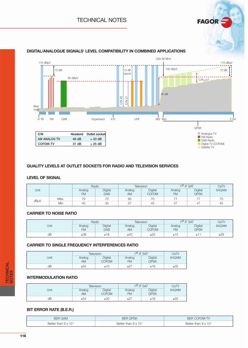
116
TECHNICAL NOTES
TEC
HN
ICA
LN
OTE
S
47 BI FM DAB Hyperband 470 UHF 862 950 2150
QPSK
DIGITAL/ANALOGUE SIGNALS’ LEVEL COMPATIBILITY IN COMBINED APPLICATIONS
QUALITY LEVELS AT OUTLET SOCKETS FOR RADIO AND TELEVISION SERVICES
LEVEL OF SIGNAL
Radio Television 1st IF SAT CaTVUnit Analog Digital Analog Digital Analog Digital 64QAM
FM DAB AM COFDM FM QPSK
dBμVMáx. 70 70 80 70 77 77 70Mín 40 30 57 45 47 47 45
CARRIER TO NOISE RATIO
Radio Television 1st IF SAT CaTVUnit Analog Digital Analog Digital Analog Digital 64QAM
FM DAB AM COFDM FM QPSK
dB 38 18 43 25 15 11 28
BER QAM BER QPSK BER COFDM-TV
Better than 9 x 10⁻⁵ Better than 9 x 10⁻⁵ Better than 9 x 10⁻⁵
C/N Headend Outlet socket
AM ANALOG TV 46 dB 43 dB
COFDM-TV 31 dB 25 dB
CARRIER TO SINGLE FREQUENCY INTERFERENCES RATIO
Television 1st IF SAT CaTVUnit Analog Digital Analog Digital 64QAM
AM COFDM FM QPSK
dB 54 10 27 18 35
INTERMODULATION RATIO
Television 1st IF SAT CaTVUnit Analog Digital Analog Digital 64QAM
AM COFDM FM QPSK
dB 54 30 27 18 35
BIT ERROR RATE (B.E.R.)
110 dBμV 110 dBμV
100 dBμV
36 dB
15 dBtypical
C/N 12
C/N
31
C/N
46
10 dB 10 dB
C69 36 MHz
95 dBμV
Basenoise
Analogue TVFM Radio DAB Radio Digital TV (COFDM)Satélite TV

117
TEC
HN
ICA
LN
OTE
S

118

119
PR
OD
UC
TIN
DE
X
Product Index
Alphabetical index (models) ............................................. 120
Numerical index (ref. numbers)........................................ 121
INDEX Page

ALPHABETICAL INDEX (MODELS)
CBL AC3 82411 23CC 01 83701 49CCF 017 84127 103CCF 019 84019 103CCF 019 N 84020 103CCF 020 84129 103CCF SAT 84102 103CCF SAT H 84133 103CCF SAT N 84104 103CCF TRA 84111 103CCF TRN 84121 103CFR 20 83602 73CFR MMP 83203 69CFR N118 83607 59CFR N218 83604 59CFR N56V 83605 59CIF 6000 + AD 06426 36CIF 7000 + AD 07426 36CMD 3 RCA 84033 50CMD EU-ST 84032 50CNR F TRN 84014 108CNR HI 84029 108CNR MF 84012 59CNR MI 84028 108CNX 300F 83709 60CNX 300M 83708 60CP 01 83702 49CX 75F 84011 50
DA 353 35920 71DA 353 A 35922 71DA 354 35924 71DA 354 A 35925 71DB 012 85002 106DES 211 + 85370 96DES 216 + 85371 96DES 220 + 85372 96DES 225 + 85373 96DES 411 + 85380 96DES 416 + 85381 96DES 420 + 85382 96DES 425 + 85383 96Di@na G 69 6 u. 84377 13Di@na G 69 aktive 84387 13Di@na G 69 aktive 6 u 84386 13Di@na G 69 84375 13Digit 45 84380 16Digit 6u 84381 16Digit 75 84382 16DIS 204 + 85354 96DIS 409 + 85355 96DiSAT 6U 86504 54DiSAT 6V 86506 54DPO 105 86105 17D WBA 415 35934 72DXR 216 86245 99DXR 2D 86242 98DXR 334 86334 99
ECU 06 85008 102ECU 09 85009 102ECU 12 85012 102ECU 15 85015 102ECU 18 85018 102
FA 802 N 66105 86FAN 10337 80337 12FAN 10351 80351 12FAN 10369 80369 12FAN 1369 81369 12FAN 2369 82369 12FAN 4337 84337 12FAN 4351 84351 12FAN 4369 84369 12FAT 010 85041 106FM “S” 80022 11FPA 470 85042 107FT 110 F 85030 107FT 130 F 85023 69FTF 245 85052 69
GRE AT 82435 27GRM A20 82421 27GRM U30 82422 27
SAC 7415 N 35018 44SDM 6000 + 27580 38SDM 6000 + ST 27595 40SDM 7000 + 27880 38SDM 7000 + ST 27895 40SDT 6300 N 08136 37SDT 6400 N 08146 37SDT 7300 N 08137 37SDT 7400 N 08147 37SDT 6300 SB 08161 38SDT 6400 SB 08171 38SDT 7300 SB 08165 38SDT 7400 SB 08175 38SHA 6115 N 35016 44SHA 7115 N 35017 44SM 6000 + 19650 34SM 6000 + ST 19665 35SM 7000 + 19750 34SM 7000 + ST 19765 35SPS 523 69523 58SPS 6000 N 66002 47SPS 6100 + 66003 48SPS 7000 N 67002 47SPS 7100 + 67003 48SPT 204 85209 97SPT 409 85405 97SPT 613 85600 97SPT 815 85800 97SPU 40 86106 21SRM 6000 + 27660 32SRM 6000 + ST 27675 33SRM 7000 + 27760 32SRM 7000 + ST 27775 33SS BT 85020 100SS BT B 85031 100
TAP 210 85210 97TAP 212 85212 97TAP 215 85215 97TAP 220 85220 97TAP 225 85225 97TAP 412 85412 97TAP 415 85415 97TAP 420 85420 97TAP 425 85425 97TAP 615 85615 97TAP 620 85620 97TAP 625 85625 97TAP 815 85815 97TAP 820 85820 97TAP 825 85825 97TDM 6000 27460 41TDM 6000 ST 27475 42TDM 7000 27560 41TDM 7000 ST 27575 42Tedi 200 86507 74TNS 106 82427 23TRT 25 82403 22
UCF 100 85100 50UCF 200 85102 64
VNT 19 83705 49VNT 56 83004 49
WBA 433 35930 71WBA 433 A 35932 71
GRM U50 82423 27GRP 001 82428 26GRP AT 82434 27
HA 405 35945 71
IC 001 85003 106ICF 001 85051 60IFA 2000 N 35904 73IFA 400 39204 57IFA 6000 S 35914 46IFA 7000 S 35915 46IFL 6000 06900 45IFL 6000 T 06902 45IFL 7000 07900 45IFL 7000 T 07902 45
Kit PO 064 86164 18Kit PO 081 86181 18
LNB 201 86129 19LNB 204 86131 19
MB 021 85001 106MD 012 F 85028 106MDIN 5 84004 49MICROMATV 35491 67MICROMATV futura 100 35551 63MICROMATV futura 100 C 35580 62MICROMATV futura 200 35550 63MICROMATV futura 200 C 35552 62MICROMATV futura 300 35549 63MICROMATV futura 300 C 35553 62MICROMATVplus 35465 65MICROMATVplus N 35467 66Min@ 84372 15MOD 500 86515 92MST 315 82415 25MST 325 82416 25MST 430 82414 25
NEX 401 39102 55NEX 402 39200 55NEX 403 39305 55NEX 445 39421 55NEX 545 39521 55NEX 545 Bicanal 39501 56NEX 545 Penta 39571 56NEX 545 Tetra 39570 56NEX 545 Tricanal 39580 56NEX DAB 39201 55
PE DES N 85014 96PMD FF 84031 50PMD FF N 84034 59PML 32 86103 21PNT 15 82401 22PNT 25 82402 22PO 064 86064 17PO 081 86081 17PPA 200 86104 21PPS 100 86101 21PPS 806 86102 21
RC 075 85010 107
SAB 252 35252 67SAB 301 35301 68SAB 301- A 35302 68SAB 304 35304 68SAB 401 35415 68SAB 402 35402 68SAB 404 35404 68SAC 6415 N 35018 44
AB 012 T 85027 69ABF 012 85053 60ACH 045 82419 26AD 1000 36100 89AD 1000 A 36101 89AD 2300 36230 90AD 420 36420 88AD 52 36052 88AD 540 36425 89ADF HHS 84016 59AFM 6000 35004 43AFM 7000 35005 43aktive 84385 14AL 46 86246 20AMB 610 N 36810 82AMB 620 N 36820 82AMB 620 NF 36821 82AMB 621 N 36814 82AMB 623 N 36823 83AMB 624 N 36824 83AMB 630 N 36830 83AMB 631 N 36831 82AMB 632 N 36832 82AMB 632 NFT 36842 82AMB 634 N 36834 83AMB 635 N 36835 83AMB 640 N 36840 82AMB 644 N 36844 83AMB 810 36010 84AMB 820 36020 84AMB 823 36023 84AMB 824 36024 84AMB 830 36030 84AMB 831 36031 84AMB 832 36032 84AMB 834 36034 85AMB 835 36035 85AMB 836 36047 85AMB 840 36055 85AN 02 80020 11AN 03-3 80003 10AN 03-4 80004 10AN 07 80007 10ANC VT 82408 24ANT DAB 80023 11APR 035 82429 26ARG V35 82410 24ARG V40 82409 24AT 020 85007 106AT 323 85005 106ATF 020 85050 69
BIF 01 N 85159 100BIF 01 S 85164 100BIF 05 N 85160 100BIF 09 N 85161 100BIF 14 N 85162 100BPP 200 82436 21BRF 00 N 85163 100BRI D68 82425 28BRI S68 82426 28BSD 201 S 86218 101BSD 201 SDC 86221 101BSD 203 DC 86204 101BSD 203 N 86205 101BSD 210 DC 86211 101BSD 210 N 86219 101BSD 215 N 86215 101BSD 220 N 86220 101BSK N10 83111 59BST 608 83600 49BST 708 83704 49BST N06 83112 59BST N12 83109 59BST N18 83110 59BTJ 035 82418 26BTR AB 82407 23BTR AT 82405 23BTR EM 82406 23BUS ADAPTER 85193 64
C BIF 85033 100C BIF B 85034 100C BSD 86230 101C BSD B 86231 101
MOD. REF. Pág. MOD. REF. Pág. MOD. REF. Pág. MOD. REF. Pág.
A
B
C
D
E
F
G
H
I
K
L
M
N
P
R
S
T
U
V
W
120
PR
OD
UC
TIN
DE
X

121
NUMERICAL INDEX (REF. NUMBERS)
06426 CIF 6000 + AD 3606900 IFL 6000 4506902 IFL 6000 T 4507426 CIF 7000 +AD 3607900 IFL 7000 4507902 IFL 7000 T 4508136 SDT 6300 N 3708137 SDT 7300 N 3708146 SDT 6400 N 3708147 SDT 7400 N 3708161 SDT 6300 SB 3808171 SDT 6400 SB 3808165 SDT 7300 SB 3808175 SDT 7400 SB 3819650 SM 6000 + 3419665 SM 6000 + ST 3519750 SM 7000 + 3419765 SM 7000 + ST 3527460 TDM 6000 4127475 TDM 6000 ST 4227560 TDM 7000 4127575 TDM 7000 ST 4227580 SDM 6000 + 3827595 SDM 6000 + ST 4027660 SRM 6000 + 3227675 SRM 6000 + ST 3327760 SRM 7000 + 3227775 SRM 7000 + ST 3327880 SDM 7000 + 3827895 SDM 7000 + ST 4035004 AFM 6000 4335005 AFM 7000 4335016 SHA 6115 N 4435017 SHA 7115 N 4435018 SAC 6415 N 4435018 SAC 7415 N 4435252 SAB 252 6735301 SAB 301 6835302 SAB 301- A 6835304 SAB 304 6835402 SAB 402 6835404 SAB 404 6835415 SAB 401 6835465 MICROMATVplus 6535467 MICROMATVplus N 6535491 MICROMATV 6735549 MICROMATV futura 300 6335550 MICROMATV futura 200 6335551 MICROMATV futura 100 6335552 MICROMATV futura 200 C 6235553 MICROMATV futura 300 C 6235580 MICROMATV futura 100 C 6235904 IFA 2000 N 7335914 IFA 6000 S 4635915 IFA 7000 S 4635920 DA 353 7135922 DA 353 A 7135924 DA 354 8335925 DA 354 A 8335930 WBA 433 7135930 WBA 433 A 7135934 D WBA 415 7235945 HA 405 7136010 AMB 810 8436020 AMB 820 8436023 AMB 823 8436024 AMB 824 8436030 AMB 830 8436031 AMB 831 8436032 AMB 832 8436034 AMB 834 8536035 AMB 835 8536047 AMB 836 8536052 AD 52 8836055 AMB 840 8536100 AD 1000 89
36101 AD 1000 A 8936230 AD 2300 9036420 AD 420 8836425 AD 540 8936810 AMB 610 N 8236814 AMB 621 N 8236820 AMB 620 N 8236821 AMB 620 NF 8236823 AMB 623 N 8336824 AMB 624 N 8336830 AMB 630 N 8336831 AMB 631 N 8236832 AMB 632 N 8236834 AMB 634 N 8336835 AMB 635 N 8336840 AMB 640 N 8236842 AMB 632 NFT 8236844 AMB 644 N 8339102 NEX 401 5539200 NEX 402 5539201 NEX DAB 5539204 IFA 400 5739305 NEX 403 5539421 NEX 445 5539501 NEX 545 Bicanal 5639521 NEX 545 5539570 NEX 545 Tetra 5639571 NEX 545 Penta 5639580 NEX 545 Tricanal 5666002 SPS 6000 N 4766003 SPS 6100 + 4866105 FA 802 N 8667002 SPS 7000 N 4767003 SPS 7100 + 4869523 SPS 523 5880003 AN 03-3 1080004 AN 03-4 1080007 AN 07 1080020 AN 02 1180022 FM “S” 1180023 ANT DAB 1180337 FAN 10337 1280351 FAN 10351 1280369 FAN 10369 1281369 FAN 1369 1282369 FAN 2369 1282401 PNT 15 2282402 PNT 25 2282403 TRT 25 2282405 BTR AT 2382406 BTR EM 2382407 BTR AB 2382408 ANC VT 2482409 ARG V40 2482410 ARG V35 2482411 CBL AC3 2382414 MST 430 2582415 MST 315 2582416 MST 325 2582418 BTJ 035 2682419 ACH 045 2682421 GRM A20 2782422 GRM U30 2782423 GRM U50 2782425 BRI D68 2882426 BRI S68 2882427 TNS 106 2382428 GRP 001 2682429 APR 035 2682434 GRP AT 2782435 GRE AT 2782436 BPP 200 2183004 VNT 56 4983109 BST N12 5983110 BST N18 5983111 BSK N10 59
83112 BST N06 5983203 CFR MMP 6983600 BST 608 4983602 CFR 20 8683604 CFR N218 5983605 CFR N56V 5983607 CFR N118 5983701 CC 01 4983702 CP 01 4983704 BST 708 4983705 VNT 19 4983707 SPS KIT 6083708 CNX 300M 6083709 CNX 300F 6084004 MDIN 5 4984011 CX 75F 5084012 CNR MF 5984014 CNR F TRN 10884016 ADF HHS 5984019 CCF 019 10384020 CCF 019 N 10384028 CNR MI 10884029 CNR HI 10884031 PMD FF 5084032 CMD EU-ST 5084033 CMD 3 RCA 5084034 PMD FF N 5984102 CCF SAT 10384104 CCF SAT N 10384111 CCF TRA 10384121 CCF TRN 10384127 CCF 017 10384129 CCF 020 10384133 CCF SAT H 10384337 FAN 4337 1284351 FAN 4351 1284369 FAN 4369 1284372 Min@ 1584375 Di@na G69 1384377 Di@na G 69 6 u. 1384380 Digit 45 1684381 Digit 6u 1684382 Digit 75 1684385 aktive 1484386 Di@na G 69 aktive 6 u 1384387 Di@na G 69 aktive 1385001 MB 021 10685002 DB 012 10685003 IC 001 10685005 AT 323 10685008 ECU 06 10285009 ECU 09 10285010 RC 075 10785012 ECU 12 10285014 PE DES N 9685015 ECU 15 10285018 ECU 18 10285020 SS BT 10085023 FT 130 F 6985027 AB 012 T 6985028 MD 012 F 10685030 FT 110 F 10785031 SS BT B 10085033 C BIF 10085034 C BIF B 10085041 FAT 010 10685042 FPA 470 10785050 ATF 020 6985051 ICF 001 6085052 FTF 245 6985053 ABF 012 6085100 UCF 100 5085102 UCF 200 6485159 BIF 01 N 10085160 BIF 05 N 10085161 BIF 09 N 100
85162 BIF 14 N 10085163 BRF 00 N 10085164 BIF 01 S 10085193 BUS ADAPTER 6485209 SPT 204 9785210 TAP 210 9785212 TAP 212 9785215 TAP 215 9785220 TAP 220 9785225 TAP 225 9785354 DIS 204 + 9685355 DIS 409 + 9685370 DES 211 + 9685371 DES 216 + 9685372 DES 220 + 9685373 DES 225 + 9685380 DES 411 + 9685381 DES 416 + 9685382 DES 420 + 9685383 DES 425 + 9685405 SPT 409 9785412 TAP 412 9785415 TAP 415 9785420 TAP 420 9785425 TAP 425 9785600 SPT 613 9785615 TAP 615 9785620 TAP 620 9785625 TAP 625 9785800 SPT 815 9785815 TAP 815 9785820 TAP 820 9785825 TAP 825 9786064 PO 064 1786081 PO 081 1786101 PPS 100 2186102 PPS 806 2186103 PML 32 2186104 PPA 200 2186105 DPO 105 1786106 SPU 40 2186129 LNB 201 1986131 LNB 204 1986164 Kit PO 064 1886181 Kit PO 081 1886204 BSD 203 DC 10186205 BSD 203 N 10186211 BSD 210 DC 10186215 BSD 215 N 10186218 BSD 201 S 10186219 BSD 210 N 10186220 BSD 220 N 10186221 BSD 201 SDC 10186230 C BSD 10186231 C BSD B 10186242 DXR 2D 9886245 DXR 216 9986246 AL 46 2086334 DXR 334 9986504 DiSAT 6U 5486506 DiSAT 6V 5486507 Tedi 200 7486515 MOD 500 92
REF. MOD. Pág. REF. MOD. Pág. REF. MOD. Pág. REF. MOD. Pág.
PR
OD
UC
TIN
DE
X

122

123


JJK/
FAG
OR
• G
ENER
AL C
AT. 0
9-10
• G
B •
ABRI
L 20
09R
ef: 9
I083
P.V.
P.: 5
,00
Fagor Electrónica, S.Coop.
San Andrés, s/n.E-20500 Mondragón (Spain)Tel.: +34 943 712526Fax: +34 943 712893E-mail: [email protected]
www.fagorelectronica.com