Cat control valves 2015 03 en tcm11 24090
32
64 VARIVENT ® control valves Industry regulations are continually updated to stricter and higher standards. While equipment and components are required to meet these high standards, the expectation from industry buyers is to have state-of-the-art quality technology with minimal costs – operation, maintenance and service. The modular design of the VARIVENT ® valve system allows individual customization for specific tasks. These adjustments create better efficiency for system operators. The VARIVENT ® systems don't require many parts, thereby reducing the need for large spare parts inventories. Integration of control valves in the process control system directly influences the quality of control and the product. This is a prerequisite for preventive maintenance as well as better efficiency of the process system. Function of the valve Control valves serve as actuator elements in the control circuits. The respective actuator valve acts as a throttle device that sets a desired flow rate in a pipe. Technical configuration The linear- or equal-percentage control cone as well as the corresponding valve seat is placed in the fully cleanable, dead- zone-free VARIVENT ® housing. Uncomplicated adjustments to changing operating conditions are possible due to the replaceable seat ring with control cone. Visual inspections of the control valve are simplified by the open lantern, which also indicates any leakages. Clamp connections between the individual modules permit quick installation and maintenance of the control valve. Type S control valves are wet-room compatible. The options spring- to-close (NC)/spring-to-open (NO) of the valve can be selected freely due to reversibility of the actuators. Special positioners specify the stroke with very high accuracy. Several Kvs values, per nominal width, are possible due to the suitable combinations of seat ring and control cone. Thus, the valve can be optimally adjusted to the process. Soft and metallically sealing valve discs are available. General benefits Proven seal geometry Dead-zone-free VARIVENT ® housing Maximum efficiency in cleaning Low spare part stocks GEA Tuchenhagen VARIVENT ® Valves with Special Functions Overview VARIVENT ® Control Valve
description
http://www.gea.com/global/en/binaries/CAT-Control-Valves-2015-03-EN_tcm11-24090.pdf
Transcript of Cat control valves 2015 03 en tcm11 24090

64
VARIVENT® control valves
Industry regulations are continually updated to stricter and higher standards. While equipment and components are required to meet these high standards, the expectation from industry buyers is to have state-of-the-art quality technology with minimal costs – operation, maintenance and service.
The modular design of the VARIVENT® valve system allows individual customization for specific tasks. These adjustments create better efficiency for system operators. The VARIVENT® systems don't require many parts, thereby reducing the need for large spare parts inventories.
Integration of control valves in the process control system directly influences the quality of control and the product. This is a prerequisite for preventive maintenance as well as better efficiency of the process system.
Function of the valve
Control valves serve as actuator elements in the control circuits. The respective actuator valve acts as a throttle device that sets a desired flow rate in a pipe.
Technical configuration
The linear- or equal-percentage control cone as well as the corresponding valve seat is placed in the fully cleanable, dead-zone-free VARIVENT® housing. Uncomplicated adjustments to changing operating conditions are possible due to the replaceable seat ring with control cone. Visual inspections of the control valve are simplified by the open lantern, which also indicates any leakages.
Clamp connections between the individual modules permit quick installation and maintenance of the control valve. Type S control valves are wet-room compatible. The options spring-to-close (NC)/spring-to-open (NO) of the valve can be selected freely due to reversibility of the actuators.
Special positioners specify the stroke with very high accuracy. Several Kvs values, per nominal width, are possible due to the suitable combinations of seat ring and control cone. Thus, the valve can be optimally adjusted to the process. Soft and metallically sealing valve discs are available.
General benefits
Proven seal geometry
Dead-zone-free VARIVENT® housing
Maximum efficiency in cleaning
Low spare part stocks
GEA Tuchenhagen VARIVENT® Valves with Special Functions
Overview VARIVENT® Control Valve

65
Application examples
The necessity to adhere to the strict standards in food production requires that control valves be customized for the highest hygienic demands in the food industry.
Any contamination would endanger the product also in the production of medical products in the pharmaceutics industry, in chemical process plants, as well as in the technical use of enzymes, cells and micro-organisms. Therefore, it is necessary to use hygienic control valves with no dead-zones, that can be cleaned efficiently and without residual residue.
VARIVENT® valves permit low-germ processes. The actuator valves meet highly hygienic demands and make it possible to conduct pipe cleaning through efficient CIP or SIP processes.
S-series control valves are used for pressure control, flow control or to mix liquids. Typical applications are: pressure modulation, yeast control or filling. There are different control valves for diverse control tasks (e.g. for recipe management, batch log and dosing) available.
Special features
Low maintenance and installation effort by clamped connections
Linear- and equal-percentage control cones
Stainless steel actuator
Modular design for flexible optimization for application conditions
Soft- or metal-sealing valve discs
Positioners for many different applications
Closed position of a control valve with a seal
GEA Tuchenhagen VARIVENT® Valves with Special Functions
Overview VARIVENT® Control Valve
4

66
VARIVENT® type S
The VARIVENT® modular system has many versions available for optimizing the valves in the process system. Divert valves are also available for mixing or distribution of products. Different cone valve seat combinations permit user-specific optimization for each particular plant process.
Housing combinations
VARIVENT® type S control valves are available with different housing combinations.
Valve seat version
The clamped housing connection is characterized by a high level of flexibility when it comes to installing the valve. The port orientation of the valve can be adapted to the pipeline system in question.
The ease of replacing the seat ring with the associated valve disc allows for adjustment of the desired Kvs value.
For the housing combinations L and T, the vertical port is connected to the valve housing with a clamping connection.
* Only for use in the gas area, e.g. in gas blocks (brewery)
Kvs values
Nominal width
0.1* 0.16*0.25* 0.4* 0.63* 1* 1.6 2.5 4 6.3 10 16 25 35 60 80 100 160 200 260 380
DN 25 • • • • • • • • • • •
DN 40 • • • •
DN 50 • • • •
DN 65 • • •DN 80 • • •DN 100 • • • •DN 125 • • • •DN 150 • • •
OD 1" • • • • • • • • • • •
OD 1 ½" • • • •
OD 2" • • • •
OD 2 ½" • • •OD 3" • • •OD 4" • • • •OD 6" • • •
IPS 2" • • • •
IPS 3" • • •IPS 4" • • • •IPS 6" • • •
Clamped housing connection: Seat ring clamped by clamping
connection
L0-housing
GEA Tuchenhagen VARIVENT® Valves with Special Functions
Overview VARIVENT® Control Valve

67
Control characteristics
The characteristic curve of a control valve is defined as the dependence of the Kv value from the stroke, specified by the shape of the control cone. Linear- or equal-percentage control cones are available.
For a valve with a linear characteristic curve, the Kv value changes continually at a ratio to the stroke, while the equal-percentage characteristic curve shows a percentage change of the particular Kv value that is identical to the stroke change.
A linear characteristic curve of the valve is wanted for controls where the control valve causes more than 30 % of the total pressure drop, e.g. in level control. In all other applications, use of an equal-percentage control cone is recommended. This is the case in approx. 90 % of all applications.
The Kvs value is defined as the flow in m³/h of water at 5–30 °C, which flows through the valve at full opening at a pressure drop of 1 bar.
Usually, the Kvs value of the valve is chosen approx. 30 % larger than the maximum Kv value calculated for the respective operating conditions. This compensates the tolerance of the Kvs value. Therefore, it is also possible to adjust the maximum flow.
The control valves with a 3-stage seat (type S_K) have linear control characteristics. They are used to reduce cavitation and noise and are mostly used for large differential pressures.
The divert valves are available as flow mixer (type S_W) or flow divider (type S_X). They are only available with linear control cones in the metallic-sealing design.
Control valve with linear control cone
Control valve with equal-percentage control cone
GEA Tuchenhagen VARIVENT® Valves with Special Functions
Overview VARIVENT® Control Valve
4.1

68
Sealing acc. to the VARIVENT® principle
The hygienic control valves are characterized by special seal technology. The metallic stop design prolongs the life of the seal because of its symmetrical wear with every stroke. This allows for extended time between required maintenance services with the process system, thereby allowing for continuous production and shorter downtimes.
The special groove shape in the valve disc ensures the seal has a secure hold at all times up to a pressure differential of 10 bar during switching. To minimize the danger of cavitation, the pressure loss between the upper and the lower housing should be kept as low as possible. The seal geometry was optimized using FEM calculations.
Seals
Long operating time
Vacuum-proof
Selection of FDA-compliant seal materials
•EPDM
•FKM
•HNBR
If additional shut-off functions do not have to be performed, or if a higher leakage rate of the seat seal can be tolerated, then the control valves with a metal seat design can be used. These valves offer the benefit of lower maintenance requirements.
Representation of the stress load of the housing O-ring and the V-ring
Metal seat design
GEA Tuchenhagen VARIVENT® Valves with Special Functions
Overview VARIVENT® Control Valve

69
Pipe classes
Standard VARIVENT® valve housings are supplied with welding ends, although the valves can be delivered with various connection fittings as an option.
The dimensions of the welding ends comply with the following standards:• Metric: Outside diameter acc. to DIN 11850,
series II; DIN 11866, series A• Inch OD: Outside diameter based on
ASME-BPE-a-2004, DIN 11866, series C• Inch IPS: Outside diameter acc. to IPS sched. 5
Surfaces
The standard for surfaces in contact with the product depends on the particular nominal width standard:• Metric, inch OD: Ra ≤ 0.8 μm• Inch IPS: Ra ≤ 1.2 μm
Higher-quality surfaces are an available option.
Surfaces not in contact with the product (housing) are matte blasted as standard. Alternatively, a ground outer surface is available.
Materials
Components in contact with the product are produced from 1.4404/AISI 316 L, while those not in contact with the product use 1.4301/AISI 304. Other materials, e.g. for use when handling aggressive fluids, are available upon request.
For detailed information about the properties of the materials, refer to the material properties table.
Works certificate and acceptance test certificate
Optionally, the valve housings and internal components can be supplied with a works certificate 2.2 or an acceptance test certificate 3.1 acc. to EN 10204.
If 3.1 acceptance test certificates are required, please notify us of this when placing the order.
Seal materials
Seals in contact with the product are EPDM (standard), HNBR, FKM and FFKM (upon request; not available for all valve types). NBR material is used for seals not in contact with the product. Other materials for seals in contact with the product are available upon request. EPDM will be supplied if no seal material is specified in the orders.
The mixing constituents of our seal materials are contained in the FDA White List and are in accordance with FOOD and DRUG (FDA) guidelines 21 CFR Part 177.2600 or 21 CFR 177.1550: "Rubber articles intended for repeated use".
The resistance of the seal material depends on the nature and temperature of the product being transported. The contact time with certain products can negatively affect the service life of seals.
For detailed information about the properties of the seal materials, refer to the seal material properties table.
GEA Tuchenhagen VARIVENT® Valves with Special Functions
Technical Data VARIVENT® Control Valve
4.1
70
Operating pressure
The valves can be operated down to a negative pressure of –0.95 bar. The maximum product pressure for which the standard valves can be configured is 10 bar. Upon request, individual valve types can be supplied with the nominal pressure level of PS20. It should be noted in this case, however, that when switching soft-sealing valves, the pressure differential between the upper and lower housing is only allowed to be 10 bar at most.
Actuator types
The modular structure of VARIVENT® control valves makes it possible to equip them with different actuator sizes. The required actuator size is adjusted to the process requirements when ordered.
Recommended flow direction
If possible, the valves should close against the flow direction in order to avoid water hammer.
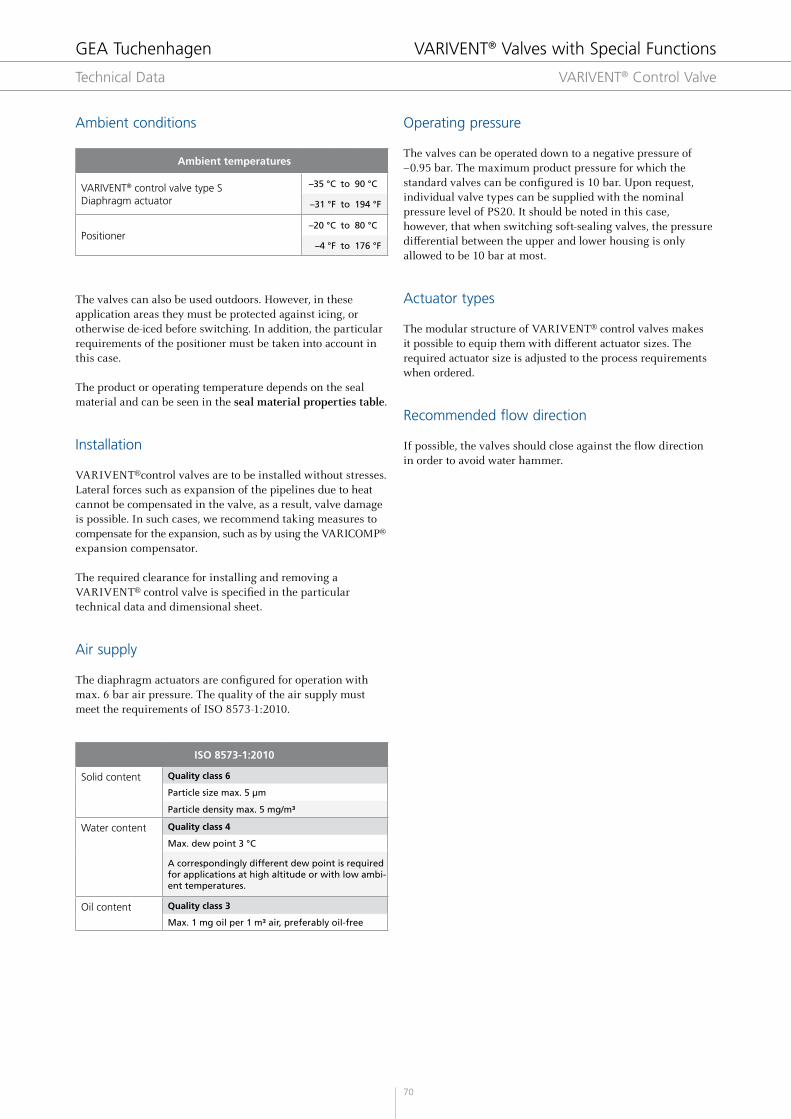
ISO 8573-1:2010
Solid content Quality class 6
Particle size max. 5 μm
Particle density max. 5 mg/m³
Water content Quality class 4
Max. dew point 3 °C
A correspondingly different dew point is required for applications at high altitude or with low ambi-ent temperatures.
Oil content Quality class 3
Max. 1 mg oil per 1 m³ air, preferably oil-free
Ambient conditions
The valves can also be used outdoors. However, in these application areas they must be protected against icing, or otherwise de-iced before switching. In addition, the particular requirements of the positioner must be taken into account in this case.
The product or operating temperature depends on the seal material and can be seen in the seal material properties table.
Installation
VARIVENT®control valves are to be installed without stresses. Lateral forces such as expansion of the pipelines due to heat cannot be compensated in the valve, as a result, valve damage is possible. In such cases, we recommend taking measures to compensate for the expansion, such as by using the VARICOMP® expansion compensator.
The required clearance for installing and removing a VARIVENT® control valve is specified in the particular technical data and dimensional sheet.
Air supply
The diaphragm actuators are configured for operation with max. 6 bar air pressure. The quality of the air supply must meet the requirements of ISO 8573-1:2010.
Ambient temperatures
VARIVENT® control valve type S Diaphragm actuator
–35 °C to 90 °C
–31 °F to 194 °F
Positioner–20 °C to 80 °C
–4 °F to 176 °F
GEA Tuchenhagen VARIVENT® Valves with Special Functions
Technical Data VARIVENT® Control Valve

71
Main alloy elements in % by mass
Material number
Short name Similar materials WS***Cr
(Chrome)Ni
(Nickel)
Mo (Molybde-
num)
C max. (Carbon)
1.4301* X5CrNi18-10 AISI 304 BS 304S15 SS2332 18 17.5 – 19.5 8.0 – 10.5 – 0.07
1.4404** X2 CrNiMo 17-12-2 AISI 316L BS 316S11 SS2348 25 16.5 – 18.5 10.0 – 13.0 2.0 – 2.5 0.03
1.4435 X2 CrNiMo 18-14-3 AISI 316L BS 316S11 SS2353 27 17.0 – 19.0 12.5 – 15.0 2.5 – 3.0 0.03
1.4462 X2 CrNiMoN 22-5-3 2205 BS 318S13 SS2377 37 21.0 – 23.0 4.5 – 6.5 2.5 – 3.5 0.03
1.4410 X2 CrNiMoN 22-5-3 SAF 2507® – SS2328 39 24.0 – 26.0 6.0 – 8.0 3.0 – 4.5 0.03
1.4529 X1 NiCrMoCuN 25-20-7 AISI 926 – – 42 19.0 – 21.0 24.0 – 26.0 6.0 – 7.0 0.02
AL-6XN® – – – – 42 20.0 – 22.0 23.5 – 25.5 6.0 – 7.0 0.03
1.4539 X1 NiCrMoCu 25-20-5 AISI 904L BS 904S13 SS2562 35 19.0 – 21.0 24.0 – 26.0 4.0 – 5.0 0.02
2.4602NiCr21Mo14W
HASTELLOY C-22– – – 69 20.0 – 22.0 – 12.5 – 14.5 0.01
2.4819NiMo16Cr15W
HASTELLOY C-276N 10276 – – 75 14.5 – 16.5 – 15.0 – 17.0 0.01
Material properties
Seal material properties
Other applications on request * Depending on the installation situation ** Inorganic acids include hydrochloric acid, nitric acid, sulphuric acid
Seal material EPDM FKM HNBR FFKM
General application temperature*−40 to 135 °C−40 to 275 °F
−10 to 200 °C14 to 392 °F
−25 to 140 °C−13 to 284 °F
−10 to 230 °C14 to 446 °F
Medium ConcentrationAt permitted
operating temperature
Alkali
≤ 3 % up to 80 °C + + +
≤ 5 % up to 40 °C + +
≤ 5 % up to 80 °C + − − +
> 5 % − − +
Inorganic acid**
≤ 3 % up to 80 °C + + + +
≤ 5 % up to 80 °C + +
> 5 % up to 100 °C − + − +
Water up to 80 °C + + + +
Steam up to 135 °C +
Steam, approx. 30 min
up to 150 °C + − +
Hydrocarbons/ fuels
− + +
Products containing grease
≤ 35 % + + + +
> 35 % − + + +
Oils − + + +
+ = Good resistance = Reduced service life
− = Not resistant
* Standard material for components not in contact with the product** Standard material for components in contact with the product (other materials available on request)*** Effective sum of stainless steels = % Cr + 3.3 * (% Mo + 0.5 W) + 20 N
GEA Tuchenhagen VARIVENT® Valves with Special Functions
Technical Data VARIVENT® Control Valve
4.1
72
Diaphragm actuatorControl Valves
GEA Tuchenhagen
Valve Selection Matrix

73
Analogue or digital SAMSON
positioner
3-stage seat, reduction of high
differential pressures
Divert valve, product-merging
Divert valve,product distribution
VARIVENT®
control valve type S_K
VARIVENT®
control valve type S_W
VARIVENT®
control valve type S_X
Linear characteristic curve
Equal-percentage characteristic curve
VARIVENT®
control valve type S_F
VARIVENT®
control valve type S_J
VARIVENT® Valves with Special Functions
VARIVENT® Control Valve
4.1

74
Technical data of the standard version
Control characteristics Equal-percentage
Recommended flow direction From bottom to top
Material in contact with the product 1.4404 / AISI 316 L
Material not in contact with the product 1.4301 / AISI 304
Seal material in contact with the product EPDM, FKM, HNBR
Ambient temperature 0 to 45 °C
Air supply pressure Max. 6 bar (max. 87 psi) Certificates
Product pressure DN 25 – 65, OD 1" – 2 ½", IPS 2"
16 bar*
DN 80 – 150, OD 3" – 6", IPS 3" – 6"
10 bar
Surface in contact with the product DN, OD Ra ≤ 0.8 μm
IPS Ra ≤ 1.2 μm
External housing surface Matte blasted
Positioner I/P positioner; type 3725
Actuator type Diaphragm actuator air/spring
Connection fittings Welding end
Identification Adhesive ID tag
Valve seat version Clamped seat ring
Certificates
Pipe Housing Diaphragm surface 175 cm² Diaphragm surface 350 cm² Diaphragm surface 750 cm² Valve
Nominal width
Ø [mm]
C [mm]
A [mm]
B [mm]
D [mm]
H [mm]
D [mm]
H [mm]
D [mm]
H [mm]
X[mm]
DN 25 28.0 × 1.50 90.0 50.0 58.0 215 343.00 – – – – 393.00
DN 40 41.0 × 1.50 90.0 62.0 64.0 215 349.00 280 353.00 – – 415.00
DN 50 53.0 × 1.50 90.0 74.0 70.0 215 355.00 280 359.00 – – 433.00
DN 65 70.0 × 2.00 125.0 96.0 83.0 215 366.00 280 370.00 – – 466.00
DN 80 85.0 × 2.00 125.0 111.0 90.5 215 373.50 280 377.50 – – 488.50
DN 100 104.0 × 2.00 125.0 130.0 100.0 – – 280 387.00 390 444.00 574.00
DN 125 129.0 × 2.00 150.0 155.0 112.5 – – – – 390 456.50 611.50
DN 150 154.0 × 2.00 150.0 180.0 125.0 – – – – 390 538.00 718.00
OD 1" 25.4 × 1.60 90.0 46.0 56.0 215 341.00 280 345.00 – – 391.00
OD 1 ½" 38.1 × 1.60 90.0 59.0 62.5 215 350.50 280 354.50 – – 413.50
OD 2" 50.8 × 1.60 90.0 71.5 69.0 215 356.75 280 360.75 – – 432.25
OD 2 ½" 63.5 × 1.60 125.0 90.0 80.0 215 370.00 280 374.00 – – 464.00
OD 3" 76.2 × 1.60 125.0 103.0 86.5 215 – 280 380.50 – 437.50 540.50
OD 4" 101.6 × 2.00 125.0 127.5 99.0 – – 280 388.75 390 445.75 573.25
OD 6" 152.4 × 2.77 150.0 177.0 123.0 – – – – 390 536.50 713.50
IPS 2" 60.3 × 2.00 114.3 81.0 73.5 215 351.50 280 355.50 – – 436.50
IPS 3" 88.9 × 2.30 152.5 115.0 92.5 215 371.50 280 375.50 – – 490.50
IPS 4" 114.3 × 2.30 152.5 140.0 105.0 – – 280 382.00 390 439.00 579.00
IPS 6" 168.2 × 2.00 152.5 192.0 131.0 – – – – 390 532.00 724.00
* A product pressure of more than 10 bar is only available for control valves with metallic control cone seal.
GEA Tuchenhagen VARIVENT® Valves with Special Functions
VARIVENT® Control Valve, Type S Equal-Percentage Characteristic Curve

75
Position Description of the order code
1 Valve type
S VARIVENT® control valve
2 Housing combinations
A B C E L
3 Supplement to the valve type
F Equal-percentage characteristic curve
4 / 5 Nominal width (upper housing/lower housing)
DN 25 OD 1"
DN 40 OD 1 ½"
DN 50 OD 2" IPS 2"
DN 65 OD 2 ½"
DN 80 OD 3" IPS 3"
DN 100 OD 4" IPS 4"
DN 125
DN 150 OD 6" IPS 6"
6 Non-actuated position
Z Spring-to-close (NC)
A Spring-to-open (NO)
7 Control cone seal
M Metallic, no V-ring
W Soft-sealing, with V-ring
8 Kvs value
0.1 DN 25, OD 1" 2.5 DN 25, OD 1" 60 DN 65 – 100, OD 2 ½" – 4", IPS 2" – 4"
0.16 DN 25, OD 1" 4 DN 25, OD 1" 80 DN 80 – 100, OD 3" – 4", IPS 3" – 4"
0.25 DN 25, OD 1" 6.3 DN 25 – 40, OD 1" – 1 ½" 100 DN 100 – 125, OD 4", IPS 4"
0.4 DN 25, OD 1" 10 DN 25 – 50, OD 1" – 2", IPS 2" 160 DN 100 – 125, OD 4", IPS 4"
0.63 DN 25, OD 1" 16 DN 40 – 50, OD 1 ½" – 2", IPS 2" 200 DN 125 – 150, OD 6", IPS 6"
1 DN 25, OD 1" 25 DN 40 – 65, OD 1 ½" – 2 ½", IPS 2" 260 DN 125 – 150, OD 6", IPS 6"
1.6 DN 25, OD 1" 35 DN 50 – 80, OD 2" – 3", IPS 2" – 3" 380 DN 150, OD 6", IPS 6"
9 Actuator
175 Diaphragm surface 175 cm2
350 Diaphragm surface 350 cm2
750 Diaphragm surface 750 cm2
10 Actuation pressure
1 0.4 – 0.2 bar 4 1.65 – 2.65 bar 7 2.2 – 3.4 bar
2 0.8 – 2.4 bar 5 1.9 – 3.1 bar 8 2.3 – 4.2 bar
3 1.0 – 3.0 bar 6 2.1 – 3.3 bar 9 2.4 – 3.6 bar
11 Actuator material
S Stainless Steel
P Steel sheet, powder-coated
12 Seal material in contact with the product
1 EPDM (FDA)
2 FKM (FDA)
3 HNBR (FDA; to DN 100, OD 4")
13 Surface quality of the housing
1 Inside Ra ≤ 1.2 μm, outside matte blasted (IPS)
2 Inside Ra ≤ 0.8 μm, outside matte blasted (DN, OD)
14 Connection fittings
N Welding end
15 Options (See acc. to valve types)+
16 Positioner
0------- Order code for positioners, see at the end of the Section Control Valves index
T
Position 1 2 3 4 / 5 6 7 8 9 10 11 12 13 14 15 16
Code S F - / - - - - N + 0-------
The code is composed as follows, depending on the chosen configuration:
For order codes differing from the standard version, please refer to section 7 (options).
GEA Tuchenhagen VARIVENT® Valves with Special Functions
Equal-Percentage Characteristic CurveVARIVENT® Control Valve, Type S
4.1

76
Technical data of the standard version
Control characteristics Linear
Recommended flow direction From bottom to top
Material in contact with the product 1.4404 / AISI 316 L
Material not in contact with the product 1.4301 / AISI 304
Seal material in contact with the product EPDM, FKM, HNBR
Ambient temperature 0 to 45 °C
Air supply pressure Max. 6 bar (max. 87 psi) Certificates
Product pressure DN 25 – 65, OD 1" – 2 ½", IPS 2"
16 bar*
DN 80 – 150, OD 3" – 6", IPS 3"
10 bar
Surface in contact with the product DN, OD Ra ≤ 0.8 μm
IPS Ra ≤ 1.2 μm
External housing surface Matte blasted
Positioner I/P positioner; type 3725
Actuator type Diaphragm actuator air/spring
Connection fittings Welding end
Identification Adhesive ID tag
Valve seat version Clamped seat ring
Certificates
Pipe Housing Diaphragm surface 175 cm² Diaphragm surface 350 cm² Diaphragm surface 750 cm² Valve
Nominal width
Ø [mm]
C [mm]
A [mm]
B [mm]
D [mm]
H [mm]
D [mm]
H [mm]
D [mm]
H [mm]
X[mm]
DN 25 28.0 × 1.50 90.0 50.0 58.0 215 343.00 – – – – 393.00
DN 40 41.0 × 1.50 90.0 62.0 64.0 215 349.00 280 353.00 – – 415.00
DN 50 53.0 × 1.50 90.0 74.0 70.0 215 355.00 280 359.00 – – 433.00
DN 65 70.0 × 2.00 125.0 96.0 83.0 215 366.00 280 370.00 – – 466.00
DN 80 85.0 × 2.00 125.0 111.0 90.5 215 373.50 280 377.50 – – 488.50
DN 100 104.0 × 2.00 125.0 130.0 100.0 – – 280 387.00 390 444.00 574.00
DN 125 129.0 × 2.00 150.0 155.0 112.5 – – – – 390 456.50 611.50
DN 150 154.0 × 2.00 150.0 180.0 125.0 – – – – 390 538.00 718.00
OD 1" 25.4 × 1.60 90.0 46.0 56.0 215 341.00 280 345.00 – – 391.00
OD 1 ½" 38.1 × 1.60 90.0 59.0 62.5 215 350.50 280 354.50 – – 413.50
OD 2" 50.8 × 1.60 90.0 71.5 69.0 215 356.75 280 360.75 – – 432.25
OD 2 ½" 63.5 × 1.60 125.0 90.0 80.0 215 370.00 280 374.00 – – 464.00
OD 3" 76.2 × 1.60 125.0 103.0 86.5 215 – 280 380.50 – 437.50 540.50
OD 4" 101.6 × 2.00 125.0 127.5 99.0 – – 280 388.75 390 445.75 573.25
OD 6" 152.4 × 2.77 150.0 177.0 123.0 – – – – 390 536.50 713.50
IPS 2" 60.3 × 2.00 114.3 81.0 73.5 215 351.50 280 355.50 – – 436.50
IPS 3" 88.9 × 2.30 152.5 115.0 92.5 215 371.50 280 375.50 – – 490.50
IPS 4" 114.3 × 2.30 152.5 140.0 105.0 – – 280 382.00 390 439.00 579.00
IPS 6" 168.2 × 2.00 152.5 192.0 131.0 – – – – 390 532.00 724.00
* A product pressure of more than 10 bar is only available for control valves with metallic control cone seal.
GEA Tuchenhagen VARIVENT® Valves with Special Functions
VARIVENT® Control Valve, Type S Linear Characteristic Curve

77
Position Description of the order code
1 Valve type
S VARIVENT® control valve
2 Housing combinations
A B C E L
3 Supplement to the valve type
J Linear characteristic curve
4 / 5 Nominal width (upper housing/lower housing)
DN 25 OD 1"
DN 40 OD 1 ½"
DN 50 OD 2" IPS 2"
DN 65 OD 2 ½"
DN 80 OD 3" IPS 3"
DN 100 OD 4" IPS 4"
DN 125
DN 150 OD 6" IPS 6"
6 Non-actuated position
Z Spring-to-close (NC)
A Spring-to-close (NO)
7 Control cone seal
M Metallic, no V-ring
W Soft-sealing, with V-ring
8 Kvs value
0.1 DN 25, OD 1" 2.5 DN 25, OD 1" 60 DN 65 – 100, OD 2 ½" – 4", IPS 2" – 4"
0.16 DN 25, OD 1" 4 DN 25, OD 1" 80 DN 80 – 100, OD 3" – 4", IPS 3" – 4"
0.25 DN 25, OD 1" 6.3 DN 25 – 40, OD 1" – 1 ½" 100 DN 100 – 125, OD 4", IPS 4"
0.4 DN 25, OD 1" 10 DN 25 – 50, OD 1" – 2", IPS 2" 160 DN 100 – 125, OD 4", IPS 4"
0.63 DN 25, OD 1" 16 DN 40 – 50, OD 1 ½" – 2", IPS 2" 200 DN 125 – 150, OD 6", IPS 6"
1 DN 25, OD 1" 25 DN 40 – 65, OD 1 ½" – 2 ½", IPS 2" 260 DN 125 – 150, OD 6", IPS 6"
1.6 DN 25, OD 1" 35 DN 50 – 80, OD 2" – 3", IPS 2" – 3" 380 DN 150, OD 6", IPS 6"
9 Actuator
175 Diaphragm surface 175 cm2
350 Diaphragm surface 350 cm2
750 Diaphragm surface 750 cm2
10 Actuation pressure
1 0.4 – 0.2 bar 4 1.65 – 2.65 bar 7 2.2 – 3.4 bar
2 0.8 – 2.4 bar 5 1.9 – 3.1 bar 8 2.3 – 4.2 bar
3 1.0 – 3.0 bar 6 2.1 – 3.3 bar 9 2.4 – 3.6 bar
11 Actuator material
S Stainless Steel
P Steel sheet, plastic-coated
12 Seal material in contact with the product
1 EPDM (FDA)
2 FKM (FDA)
3 HNBR (FDA; to DN 100, OD 4")
13 Surface quality of the housing
1 Inside Ra ≤ 1.2 μm, outside matte blasted (IPS)
2 Inside Ra ≤ 0.8 μm, outside matte blasted (DN, OD)
14 Connection fittings
N Welding end
15 Options (See acc. to valve types)+
16 Positioner
0------- Order code for positioners, see at the end of the Section Control Valves index
T
Position 1 2 3 4 / 5 6 7 8 9 10 11 12 13 14 15 16
Code S J - / - - - - N + 0-------
The code is composed as follows, depending on the chosen configuration:
GEA Tuchenhagen VARIVENT® Valves with Special Functions
For order codes differing from the standard version, please refer to section 7 (options).
Linear Characteristic CurveVARIVENT® Control Valve, Type S
4.1

78
Technical data of the standard version
Control characteristics Linear
Recommended flow direction From bottom to top
Material in contact with the product 1.4404 / AISI 316 L
Material not in contact with the product 1.4301 / AISI 304
Seal material in contact with the product EPDM, FKM, HNBR
Ambient temperature 0 to 45 °C
Air supply pressure Max. 6 bar (max. 87 psi) Certificates
Product pressure DN 25 – 65, OD 1" – 2 ½", IPS 2"
16 bar
DN 80 – 100, OD 3" – 4", IPS 3 – 4"
10 bar
Surface in contact with the product DN, OD Ra ≤ 0.8 μm
IPS Ra ≤ 1.2 μm
External housing surface Matte blasted
Positioner I/P positioner; type 3725
Actuator type Diaphragm actuator air/spring
Connection fittings Welding end
Identification Adhesive ID tag
Valve seat version Clamped seat ring
Certificates
Pipe Housing Diaphragm surface 175 cm² Diaphragm surface 350 cm² Diaphragm surface 750 cm² Valve
Nominal width
Ø [mm]
C [mm]
A [mm]
D [mm]
H [mm]
D [mm]
H [mm]
D [mm]
H [mm]
X[mm]
DN 25 28.0 × 1.50 90.0 On request 215 343.00 – – – – 393.00
DN 40 41.0 × 1.50 90.0 On request 215 349.00 280 353.00 – – 415.00
DN 50 53.0 × 1.50 90.0 On request 215 355.00 280 359.00 – – 433.00
DN 65 70.0 × 2.00 125.0 On request 215 366.00 280 370.00 – – 466.00
DN 80 85.0 × 2.00 125.0 On request 215 373.50 280 377.50 – – 488.50
DN 100 104.0 × 2.00 125.0 On request – – 280 387.00 390 444 574.00
OD 1" 25.4 × 1.60 90.0 On request 215 341.00 280 345.00 – – 391.00
OD 1 ½" 38.1 × 1.60 90.0 On request 215 350.50 280 354.50 – – 413.50
OD 2" 50.8 × 1.60 90.0 On request 215 356.75 280 360.75 – – 432.25
OD 2 ½" 63.5 × 1.60 125.0 On request 215 370.00 280 374.00 – – 464.00
OD 3" 76.2 × 1.60 125.0 On request 215 – 280 380.50 – 437.5 540.50
OD 4" 101.6 × 2.00 125.0 On request – – 280 388.75 390 445.75 573.25
IPS 2" 60.3 × 2.00 114.3 On request 215 351.50 280 355.50 – – 436.50
IPS 3" 88.9 × 2.30 152.5 On request 215 371.50 280 375.50 – – 490.50
IPS 4" 114.3 × 2.30 152.5 On request – – 280 382.00 390 439 579.00
GEA Tuchenhagen VARIVENT® Valves with Special Functions
VARIVENT® Control Valve, Type S 3-stage Seat

79
Position Description of the order code
1 Valve type
S VARIVENT® control valve
2 Housing combinations
A B C E
3 Supplement to the valve type
K 3-stage seat, linear characteristic curve
4 / 5 Nominal width (upper housing/lower housing)
DN 25 OD 1"
DN 40 OD 1 ½"
DN 50 OD 2" IPS 2"
DN 65 OD 2 ½"
DN 80 OD 3" IPS 3"
DN 100 OD 4" IPS 4"
DN 125
DN 150 OD 6" IPS 6"
6 Non-actuated position
Z Spring-to-close (NC)
A Spring-to-close (NO)
7 Control cone seal
M Metallic, no V-ring
W Soft-sealing, with V-ring
8 Kvs value
2.3 DN 25, OD 1"
8.0 DN 40, OD 1 ½"
12.6 DN 50, OD 2", IPS 2"
24.1 DN 65, OD 2 ½"
30.7 DN 80, OD 3", IPS 3"
58.2 DN 100, OD 4", IPS 4"
9 Actuator
175 Diaphragm surface 175 cm2
350 Diaphragm surface 350 cm2
750 Diaphragm surface 750 cm2
10 Actuation pressure
1 0.4 – 0.2 bar 4 1.65 – 2.65 bar 7 2.2 – 3.4 bar
2 0.8 – 2.4 bar 5 1.9 – 3.1 bar 8 2.3 – 4.2 bar
3 1.0 – 3.0 bar 6 2.1 – 3.3 bar 9 2.4 – 3.6 bar
11 Actuator material
S Stainless Steel
P Steel sheet, plastic-coated
12 Seal material in contact with the product
1 EPDM (FDA)
2 FKM (FDA)
3 HNBR (FDA; to DN 100, OD 4")
13 Surface quality of the housing
1 Inside Ra ≤ 1.2 μm, outside matte blasted (IPS)
2 Inside Ra ≤ 0.8 μm, outside matte blasted (DN, OD)
14 Connection fittings
N Welding end
15 Options (See acc. to valve types)+
16 Positioner
0------- Order code for positioners, see at the end of the Section Control Valves index
Position 1 2 3 4 / 5 6 7 8 9 10 11 12 13 14 15 16
Code S K - / - - - - /2F N + 0-------
The code is composed as follows, depending on the chosen configuration:
GEA Tuchenhagen VARIVENT® Valves with Special Functions
For order codes differing from the standard version, please refer to section 7 (options).
3-stage SeatVARIVENT® Control Valve, Type S
4.1

80
Technical data of the standard version
Control characteristics Linear
Recommended flow direction From bottom to top
Material in contact with the product 1.4404 / AISI 316 L
Material not in contact with the product 1.4301 / AISI 304
Seal material in contact with the product EPDM, FKM, HNBR
Ambient temperature 0 to 45 °C
Air supply pressure Max. 6 bar (max. 87 psi) Certificates
Product pressure DN 25 – 65, OD 1" – 2 ½", IPS 2"
16 bar
DN 80 – 100, OD 3" – 4", IPS 3 – 4"
10 bar
Surface in contact with the product DN, OD Ra ≤ 0.8 μm
IPS Ra ≤ 1.2 μm
External housing surface Matte blasted
Positioner I/P positioner; type 3725
Actuator type Diaphragm actuator air/spring
Connection fittings Welding end
Identification Adhesive ID tag
Valve seat version Clamped seat ring
Certificates
Pipe Housing Diaphragm surface 175 cm² Diaphragm surface 350 cm² Diaphragm surface 750 cm² Valve
Nominal width
Ø [mm]
C [mm]
A [mm]
D [mm]
H [mm]
D [mm]
H [mm]
D [mm]
H [mm]
X[mm]
DN 25 28.0 × 1.50 90.0 50.0 215 343.00 – – – – 393.00
DN 40 41.0 × 1.50 90.0 62.0 215 349.00 280 353.00 – – 415.00
DN 50 53.0 × 1.50 90.0 74.0 215 355.00 280 359.00 – – 433.00
DN 65 70.0 × 2.00 125.0 96.0 215 366.00 280 370.00 – – 466.00
DN 80 85.0 × 2.00 125.0 111.0 215 373.50 280 377.50 – – 488.50
DN 100 104.0 × 2.00 125.0 130.0 – – 280 387.00 390 444.00 574.00
OD 1" 25.4 × 1.60 90.0 46.0 215 341.00 280 345.00 – – 391.00
OD 1 ½" 38.1 × 1.60 90.0 59.0 215 350.50 280 354.50 – – 413.50
OD 2" 50.8 × 1.60 90.0 71.5 215 356.75 280 360.75 – – 432.25
OD 2 ½" 63.5 × 1.60 125.0 90.0 215 370.00 280 374.00 – – 464.00
OD 3" 76.2 × 1.60 125.0 103.0 215 – 280 380.50 – 437.50 540.50
OD 4" 101.6 × 2.00 125.0 127.5 – – 280 388.75 390 445.75 573.25
IPS 2" 60.3 × 2.00 114.3 81.0 215 351.50 280 355.50 – – 436.50
IPS 3" 88.9 × 2.30 152.5 115.0 215 371.50 280 375.50 – – 490.50
IPS 4" 114.3 × 2.30 152.5 140.0 – – 280 382.00 390 439.00 579.00
GEA Tuchenhagen VARIVENT® Valves with Special Functions
Divert Valve, Product-mergingVARIVENT® Control Valve, Type S

81
Position Description of the order code
1 Valve type
S VARIVENT® control valve
2 Housing combinations
W U Y M
3 Supplement to the valve type
W Divert valve, product-merging, linear characteristic curve
4 / 5 Nominal width (upper housing/lower housing)
DN 25 OD 1"
DN 40 OD 1 ½"
DN 50 OD 2" IPS 2"
DN 65 OD 2 ½"
DN 80 OD 3" IPS 3"
DN 100 OD 4" IPS 4"
DN 125
DN 150 OD 6" IPS 6"
6 Non-actuated position
Z Spring-to-close (NC)
A Spring-to-close (NO)
7 Control cone seal
M Metallic, no V-ring
W Soft-sealing, with V-ring
8 Kvs value
6.3 DN 25, OD 1"
16 DN 40, OD 1 ½"
25 DN 50, OD 2", IPS 2"
35 DN 65, OD 2 ½"
60 DN 80, OD 3", IPS 3"
100 DN 100, OD 4", IPS 4"
260 DN 125
360 DN 150, OD 6", IPS 6"
9 Actuator
175 Diaphragm surface 175 cm2
350 Diaphragm surface 350 cm2
750 Diaphragm surface 750 cm2
10 Actuation pressure
1 0.4 – 0.2 bar 4 1.65 – 2.65 bar 7 2.2 – 3.4 bar
2 0.8 – 2.4 bar 5 1.9 – 3.1 bar 8 2.3 – 4.2 bar
3 1.0 – 3.0 bar 6 2.1 – 3.3 bar 9 2.4 – 3.6 bar
11 Actuator material
S Stainless Steel
P Steel sheet, plastic-coated
12 Seal material in contact with the product
1 EPDM (FDA)
2 FKM (FDA)
3 HNBR (FDA; to DN 100, OD 4")
13 Surface quality of the housing
1 Inside Ra ≤ 1.2 μm, outside matte blasted (IPS)
2 Inside Ra ≤ 0.8 μm, outside matte blasted (DN, OD)
14 Connection fittings
N Welding end
15 Options (See acc. to valve types)+
16 Positioner
0------- Order code for positioners, see at the end of the Section Control Valves index
Position 1 2 3 4 / 5 6 7 8 9 10 11 12 13 14 15 16
Code S W - / - - - - /2F N + 0-------
The code is composed as follows, depending on the chosen configuration:
GEA Tuchenhagen VARIVENT® Valves with Special Functions
For order codes differing from the standard version, please refer to section 7 (options).
Divert Valve, Product-mergingVARIVENT® Control Valve, Type S
4.1

82
Technical data of the standard version
Control characteristics Linear
Recommended flow direction From bottom to top
Material in contact with the product 1.4404 / AISI 316 L
Material not in contact with the product 1.4301 / AISI 304
Seal material in contact with the product EPDM, FKM, HNBR
Ambient temperature 0 to 45 °C
Air supply pressure Max. 6 bar (max. 87 psi) Certificates
Product pressure DN 25 – 65, OD 1" – 2 ½", IPS 2"
16 bar
DN 80 – 100, OD 3" – 4", IPS 3 – 4"
10 bar
Surface in contact with the product DN, OD Ra ≤ 0.8 μm
IPS Ra ≤ 1.2 μm
External housing surface Matte blasted
Positioner I/P positioner; type 3725
Actuator type Diaphragm actuator air/spring
Connection fittings Welding end
Identification Adhesive ID tag
Valve seat version Clamped seat ring
Certificates
Pipe Housing Diaphragm surface 175 cm² Diaphragm surface 350 cm² Diaphragm surface 750 cm² Valve
Nominal width
Ø [mm]
C [mm]
A [mm]
D [mm]
H [mm]
D [mm]
H [mm]
D [mm]
H [mm]
X[mm]
DN 25 28.0 × 1.50 90.0 50.0 215 343.00 – – – – 393.00
DN 40 41.0 × 1.50 90.0 62.0 215 349.00 280 353.00 – – 415.00
DN 50 53.0 × 1.50 90.0 74.0 215 355.00 280 359.00 – – 433.00
DN 65 70.0 × 2.00 125.0 96.0 215 366.00 280 370.00 – – 466.00
DN 80 85.0 × 2.00 125.0 111.0 215 373.50 280 377.50 – – 488.50
DN 100 104.0 × 2.00 125.0 130.0 – – 280 387.00 390 444.00 574.00
OD 1" 25.4 × 1.60 90.0 46.0 215 341.00 280 345.00 – – 391.00
OD 1 ½" 38.1 × 1.60 90.0 59.0 215 350.50 280 354.50 – – 413.50
OD 2" 50.8 × 1.60 90.0 71.5 215 356.75 280 360.75 – – 432.25
OD 2 ½" 63.5 × 1.60 125.0 90.0 215 370.00 280 374.00 – – 464.00
OD 3" 76.2 × 1.60 125.0 103.0 215 – 280 380.50 – 437.50 540.50
OD 4" 101.6 × 2.00 125.0 127.5 – – 280 388.75 390 445.75 573.25
IPS 2" 60.3 × 2.00 114.3 81.0 215 351.50 280 355.50 – – 436.50
IPS 3" 88.9 × 2.30 152.5 115.0 215 371.50 280 375.50 – – 490.50
IPS 4" 114.3 × 2.30 152.5 140.0 – – 280 382.00 390 439.00 579.00
GEA Tuchenhagen VARIVENT® Valves with Special Functions
Divert Valve, Product DistributionVARIVENT® Control Valve, Type S

83
Position Description of the order code
1 Valve type
S VARIVENT® control valve
2 Housing combinations
W U Y M
3 Supplement to the valve type
X Divert valve, product distribution, linear characteristic curve
4 / 5 Nominal width (upper housing/lower housing)
DN 25 OD 1"
DN 40 OD 1 ½"
DN 50 OD 2" IPS 2"
DN 65 OD 2 ½"
DN 80 OD 3" IPS 3"
DN 100 OD 4" IPS 4"
DN 125
DN 150 OD 6" IPS 6"
6 Non-actuated position
Z Spring-to-close (NC)
A Spring-to-close (NO)
7 Control cone seal
M Metallic, no V-ring
W Soft-sealing, with V-ring
8 Kvs value
6.3 DN 25, OD 1"
16 DN 40, OD 1 ½"
25 DN 50, OD 2", IPS 2"
35 DN 65, OD 2 ½"
60 DN 80, OD 3", IPS 3"
100 DN 100, OD 4", IPS 4"
260 DN 125
360 DN 150, OD 6", IPS 6"
9 Actuator
175 Diaphragm surface 175 cm2
350 Diaphragm surface 350 cm2
750 Diaphragm surface 750 cm2
10 Actuation pressure
1 0.4 – 0.2 bar 4 1.65 – 2.65 bar 7 2.2 – 3.4 bar
2 0.8 – 2.4 bar 5 1.9 – 3.1 bar 8 2.3 – 4.2 bar
3 1.0 – 3.0 bar 6 2.1 – 3.3 bar 9 2.4 – 3.6 bar
11 Actuator material
S Stainless Steel
P Steel sheet, plastic-coated
12 Seal material in contact with the product
1 EPDM (FDA)
2 FKM (FDA)
3 HNBR (FDA; to DN 100, OD 4")
13 Surface quality of the housing
1 Inside Ra ≤ 1.2 μm, outside matte blasted (IPS)
2 Inside Ra ≤ 0.8 μm, outside matte blasted (DN, OD)
/5 Additional manual adjustment
/24 Sterile lock complete
14 Connection fittings
N Welding end
15 Options (See acc. to valve types)+
16 Positioner
0------- Order code for positioners, see at the end of the Section Control Valves index
Position 1 2 3 4 / 5 6 7 8 9 10 11 12 13 14 15 16
Code S X - / - - - - /2F N + 0-------
The code is composed as follows, depending on the chosen configuration:
GEA Tuchenhagen VARIVENT® Valves with Special Functions
For order codes differing from the standard version, please refer to section 7 (options).
Divert Valve, Product DistributionVARIVENT® Control Valve, Type S
4.1

84
Position 1 2 3 4 / 5 6 7 8 9 10 11 12 13 14 15 16
Code S B F - DN80/DN80 - Z M 80 - 350 8 - S - 1 2 N / 24 + 0-------
Position Description of the order code for options
15 Accessories
/ 24 Sterile lock complete
Technical data
Material 1.4301
Barrier fluid e.g. sterile water, condensate, steamIMPORTANT: The sterile lock is not suitable for permanent vapor application. Brief actuation is recommended after or before the switching procedure.
Available nominal widths
Metric DN 25 – 150
Inch OD OD 1" – 6"
Inch IPS IPS 2" – 6"
Typical application and description
Incorporation of the option in the order code and example
The sterile lock is used for reliable separation between the surface of the valve disc in contact with the product and the atmosphere.
Applying sterilizing media to the sterile lock prevents contamination of the product from atmosphere due to the switching movement of the valve stem (“elevator effect”).
If the media has a tendency towards crystallization, this effect can be avoided by pressurizing the sterile lock with a liquid and securing the shaft seal against damage.
Dimensions
Nominal widthConnection
[mm]Weight
[kg]
DN 25 OD 1" 6 / 4 0.4
DN 40 OD 1 ½" 6 / 4 0.8
DN 50 OD 2" IPS 2" 6 / 4 0.8
DN 65 OD 2 ½" 6 / 4 1.5
DN 80 OD 3" IPS 3" 6 / 4 1.5
DN 100 OD 4" IPS 4" 6 / 4 2.6
DN 125 6 / 4 5.9
DN 150 OD 6" IPS 6" 6 / 4 7.2
GEA Tuchenhagen VARIVENT® Valves with Special Functions
Options Sterile Lock

85
Position 1 2 3 4 / 5 6 7 8 9 10 11 12 13 14 15 16
Code S B F - DN80/DN80 - Z M 80 - 350 8 - S - 1 2 N / 2F + 0-------
Double stem control
To avoid vibrations that may result from the flow dynamics within the valve body, the control valves are optionally available with an additional lower guide of the valve shaft from a nominal width of DN80, OD 3" and IPS 3"onwards. The control valves with 3-stage seats and the divert valves are equipped with the double stem guide in all nominal widths.
Additional manual adjustment
Optionally, the diaphragm actuators can be equipped with an additional manual adjustment. This is attached on the upper actuator lid. The hand wheel can be used to manually adjust the stroke of the valve disc against the spring force of the actuator.
Changing the nominal signal range and reversing the operating direction of the diaphragm actuator without special tools is possible in the manually adjusted design as well.
Diaphragm surface 175 cm²
Diaphragm surface 350 cm²
Diaphragm surface 750 cm²
Nominal width
H1[mm]
H1[mm]
H1[mm]
DN 25 577 – –
DN 40 583 590 –
DN 50 589 596 –
DN 65 600 607 –
DN 80 608 615 –
DN 100 – 624 799
DN 125 – – 812
DN 150 – – 893
OD 1" 575 582 –
OD 1 ½" 585 592 –
OD 2" 591 598 –
OD 2 ½" 604 611 –
OD 3" – 618 793
OD 4" – 626 801OD 6" – – 892
IPS 2" 586 593 –
IPS 3" 606 613 –
IPS 4" – 619 794
IPS 6" – – 887
Position Description of the order code for options
15 Accessories
/2F Double stem control
/5 Additional manual adjustment
Incorporation of the option in the order code and example
No. 13 in the order code /2F Double stem control
No. 13 in the order code /5 Additional manual adjustment
GEA Tuchenhagen VARIVENT® Valves with Special Functions
Options Double Stem Control and Additional Manual Adjustment
4.1

86
Function of the positioner
Positioners convert an electrical or pneumatic input signal into a corresponding output signal (set position).
Description
Positioners compare the set value from a superordinate controller (PLC) to the stroke of the control valve and convert it into a pneumatic actuator pressure that is sent to the diaphragm actuator. A mechanical return of the current position of the actuator stroke can balance out changes regarding operating pressure and actuation energy automatically. This improves the accuracy and reduces the actuation time. Interferences such as friction or flow influences are balanced out by the positioner itself. The positioners can be used in the normal and split range operation.
The positioners are directly assembled to the diaphragm actuator of the control valve, which means the pneumatic connections are realized without additional tubes or hoses.
GEA Tuchenhagen VARIVENT® Valves with Special Functions
Options Positioner

87
Differentiation acc. to type of signal
Pneumatic/electropneumatic positioner A difference is made acc. to the input signal between pneumatic (p/p-) and electropneumatic (i/p-) positioners.
Pneumatic (p/p) positionersFor pneumatic devices, the input value is a mechanical signal with a pressure of 0.2 to 1 bar (3 to 15 psi) and the output value is an actuator pressure up to 6 bar (90 psi) at most.
Electropneumatic (i/p) positioners For the electropneumatic positioners, the input is an analogue direct current signal of 4 to 20 mA or a digital signal (PROFIBUS, Foundation Fieldbus). The input signal is converted into the corresponding required pressure with an integrated circuit. The output signal is an actuation pressure with up to 6 bar (90 psi).
Special features of digital positioners
Simple operation
Display with switchable reading direction
Automatic set-up (except for type 3730-0)
Independent recognition of errors in the actuator
Movement direction independent of the installation orientation
Continuous monitoring of the zero point
Minimized air consumption
Fail-safe storage of all parameters
Type 3766
Type 3725 Type 3730
Type 3767
GEA Tuchenhagen VARIVENT® Valves with Special Functions
Options Positioner
4.1
88
Type 3725 3730-0 3730-1
Digital Analog Digital
Input/output signal i/p i/p i/p
Communication
Diagnosis
Guide size 4 to 20 mA 4 to 20 mA 4 to 20 mA
Split range • • •
Supply air pressure 1.4 to 7 bar 1.4 to 7 bar 1.4 to 7 bar
Actuation pressure 0 to 7 bar 0 to 7 bar 0 to 7 bar
Options
Position indicator, 4 – 20 mA
With 3/2 directional solenoid valve
Pressure gage component • • •
AS-Interface module type 6150 • • •
Open/close position feedback
2 proximity switches (software) •
1 inductive+ 1 software proximity switch
2 proximity switches
Approval acc. to ATEX
II 2G Ex ia IIC T4 •
EEx ia • •
II 2G Ex ia IIC T6 / II 2D Ex tb IIIC T80°C
II 2G Ex ia IIC T6
IECEx •
Operating elements
Display • •
Volume throttle • • •
Buttons 3
Dial switch/push button •
Slider
Potentiometer •
DIP switch •
Setting screws
Ambient temperature –20 to +80 °C –20 to +80 °C –20 to +80 °C
Index of protection class IP66 IP66 IP66
Option in the order code 1 2 3
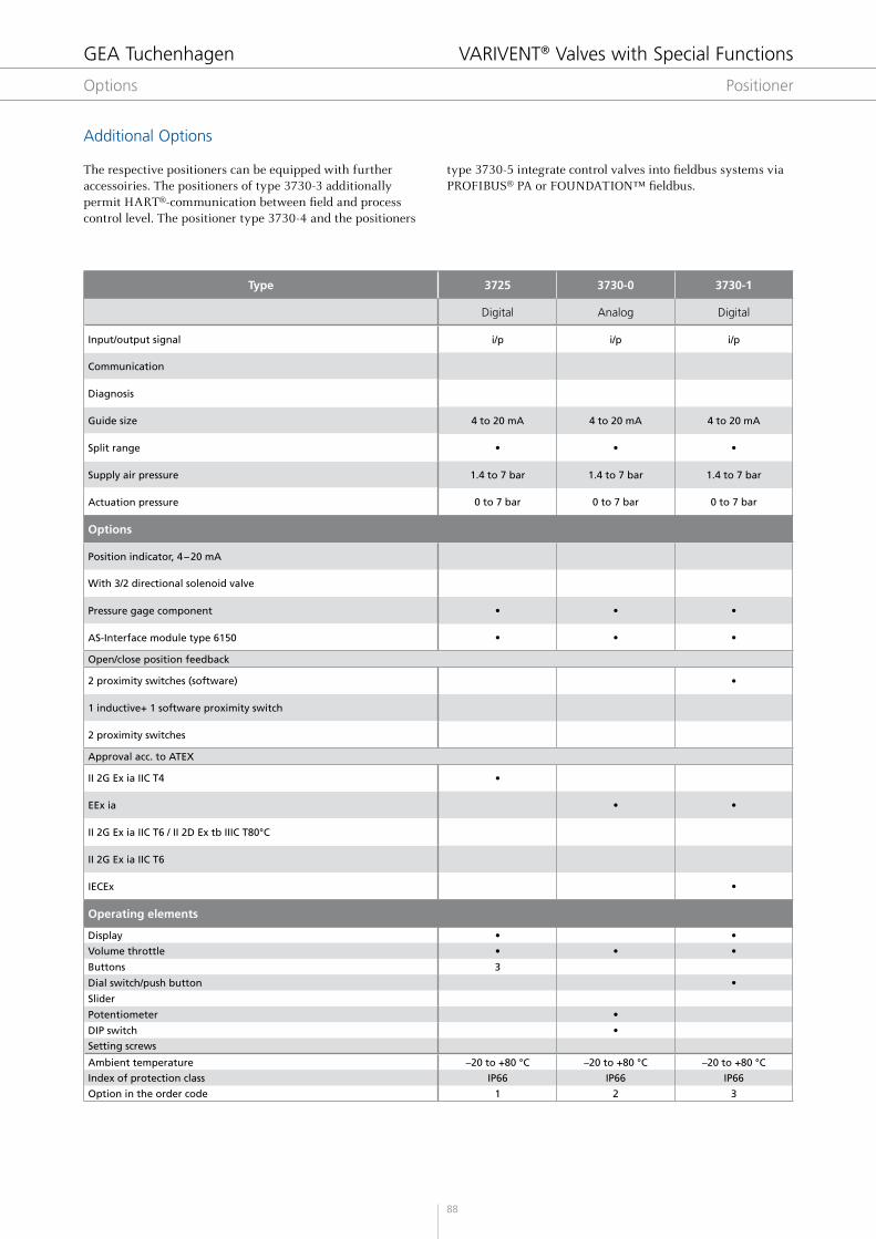
Additional Options
The respective positioners can be equipped with further accessoiries. The positioners of type 3730-3 additionally permit HART®-communication between field and process control level. The positioner type 3730-4 and the positioners
type 3730-5 integrate control valves into fieldbus systems via PROFIBUS® PA or FOUNDATION™ fieldbus.
GEA Tuchenhagen VARIVENT® Valves with Special Functions
Options Positioner

89
3730-2 3730-3 3730-4 3730-5 3766 3767
Digital Digital Digital Digital Analog Analog
i/p i/p i/p i/pp/p
can be converted to i/pi/p
can be converted to p/p
HART PROFI BUS FOUNDATION
EXPERTplus EXPERTplus EXPERTplus EXPERTplus
4 to 20 mA 4 to 20 mA – –0.2 to 1 bar(4 to 20 mA)
0 to 20 mA(0.2 to 1 bar)
• • • • • •
1.4 to 7 bar 1.4 to 7 bar 1.4 to 7 bar 1.4 to 7 bar 1.4 to 6 bar 1.4 to 6 bar
0 to 7 bar 1 to 7 bar 0 to 7 bar 0 to 3.5 bar 0 to 6 bar 0 to 6 bar
Options
• •
• • • •
• • • • • •
• •
Open/close position feedback
• • • •
• • •
• •
Approval acc. to ATEX
• • •
•
• • • • •
Operating elements
• • • •
• • • • • •
1 1 1 1
• • • •
• • • •
• •
–20 to +80 °C –20 to +80 °C –45 to +80 °C –45 to +80 °C –20 to +80 °C –20 to +80 °C
IP66 IP66 IP66 IP66 IP 54 IP 54
4 5 6 7 8 9
The optionally available 3/2 way solenoid valve for the positioner type 3720-2, 3720-3, 3730-4 and 3767 converts binary control signals into pneumatic control signals, which opens or closes the associated diaphragm actuator.
GEA Tuchenhagen VARIVENT® Valves with Special Functions
Options Positioner
4.1

90
Position Description of the order code
1 Positioner type
0 (0) without positioner
1 (1) Type 3725 I/P
2 (2) Type 3730-1 I/P
3 (3) Type 3730-0 I/P
4 (4) Type 3730-2 I/P
5 (5) Type 3730-3 I/P HART
6 (6) Type 3730-5 I/P (Fieldbus)
7 (7) Type 3730-4 I/P Profibus
8 (8) Type 3766 P/P
9 (9) Type 3767 I/P
2 Solenoid valve
– Without
1 With 3/2 directional solenoid valve 24 V DC
3 Open/close position feedback
– Without information
S 2 proximity switches (software)
I 1 proximity switch
F 2 proximity switches
4 Position feedback
– Without position feedback
2 With position feedback 4 – 20 mA
5 Ex-design
– Without Ex-protection certificate
E With Ex-protection certificate*
6 Pressure gage component
– Without pressure gage assembly
1 With pressure gage assembly
7 Air connection
M Metric for air hose Ø 6/4 mm
Z Inch for air hose Ø OD ¼" (6.35/4.35 mm)
8 ASI module
– Without ASI module
A With ASI module
Position 1 2 3 4 5 6 7 8
Code +
The code to describe the positioner is attached to the order code of the control valve.
The code is composed as follows, depending on the chosen configuration:
Positioner
* For the available ATEX approvals please see table “further options”.
GEA Tuchenhagen VARIVENT® Valves with Special Functions
Options

91
Formula symbols used:
Q = Flow rate (liquid) [m3/h] QN = Flow rate (gas) at the standard condition [m3/h] p1 = Pressure upstream of the valve [bar abs.] p2 = Pressure downstream of the valve [bar abs.] Δp = Differential pressure [bar] ρ = Density (liquid) [kg/m3] ρN = Density (gas) at the standard condition [kg/m3] η = Dynamic viscosity [mPas] T1 = 273+t1 = Operating temperature [Kelvin] = Operating temperature [°C]
1.Kvvaluecalculation:
Kv- value = Valve-stroke-dependent flow volume Q in m3/h referring to water at t = 5 to 30 °C at a differential pressure of Δp = p1 – p2 = 1 bar in the control valve.
For low-viscose liquids: For high-viscose liquids:
For gases:
• subcritical pressure reduction at Δp < 0.5 p1 or p2 > 0.5 p1
Example 1: low-viscose liquid
Q = 30 m3/h, = 1000 kg/m3, Δp = 0.5 bar, p1 = 7 bar
• overcritical pressure reduction at Δp < 0.5 p1 or p2 < 0.5 p1
Over-critical pressure reduction = strong noise development
Calculation as below
At different operating conditions: Highest throughput and lowest differential pressure.
0.46 0.52 0.59 0.68 0.8 1.00 1.35 1.9 3.0 4.9 9.5 20
0.46 0.50 0.54 0.58 0.62 0.68 0.74 0.80 0.86 0.90 0.94 0.98
=ρ
KvQ
31.6 pmh
3
=ρ ××
KvQ514
Tp p
mh
N N 1
2
3
=×
ρ ×KvQ
257 pT
mh
N
1N 1
3
=ρ
KvQ
31.6 pmhT
3
=×η×
Kv1
1.05Q
216 pmhL
23 3
< =KvKv
0.46 Kv KvT
LL > =
KvKv
20 Kv KvT
LT
< < =×
ρ0.46
KvKv
20 KvQ
F 31.6 pT
L R
< < =×
ρ0.46
KvKv
20 KvQ
F 31.6 pT
L R
0,46<KvT
KvL
<20⇒Kv=Q
FR×31,6ρΔp
0,46<KvT
KvL
<20⇒Kv=Q
FR×31,6ρΔp
= ≈Kv30
31.610000.5
42.46mh
3
0,46<KvT
KvL
<20⇒Kv=Q
FR×31,6ρΔp
GEA Tuchenhagen VARIVENT® Valves with Special Functions
Design VARIVENT® Control Valve
4.1

92
2.DeterminationoftheKvsvalueand the valve size
The chosen Kvs value must be above the calculated Kv value. This ensures that the control valve works even at deviating operating data (Reserve).
There are two cases for this:
Linear control cone
Equal-percentage control cones
3. Determination of the control cone
The characteristic curve of the control valve is defined as the dependence of the Kv value from the stroke. Control valves are performed either with an equal-percentage or a linear characteristic curve. The equal-percentage characteristic curve is characterized by stroke changes leading to same percentage changes of the particular Kv value. For a linear characteristic curve, same stroke changes cause changes to the Kv value.
The selection of the control cone depends on the ratio of thepressure reduction Δp = p1 – p2 in the control valve at maximum flow to the pressure reduction Δpges in the entire system.• Equal-percentage control cones are used if less than 30% of
the total pressure drop is caused in the line system of the control valve. Level control is a typical example for this.
• Equal-percentage control cones are used if less than 30% of the total pressure drop is caused in the line system of the control valve; these are approx. 90 % of the applications of the control valves.
Kv = 42.5 m3/h, equal-percentage control characteristics
4. Determination of the nominal width and actuator size of the valve
Calculation of the actuator forces is the basis for the actuator selection scheme. The diaphragm actuator to be chosen acc. to the required closing force is determined depending on the selected Kvs value of the valve and the maximum product pressure. This information must be specified in the order.
Example:Chosen Kvs = 80, p1 = 7 bar, (Q = 30 m3/h)
A valve nominal width of DN 80 is chosen from the data sheet. An actuator of size 350 results. Based on the flow volume, a flow speed of 1.6 m/s through the valve results.
According to the data sheet, a Kvs value of 80 m3/h must be chosen, i.e. management of the control task set requires a valve of DN 80.
Example:
=≈
Kv req.Kv value calculated
0.6
= =Kv req.42.50.6
70.8
=≈
Kv req.Kv value calculated
0.7
GEA Tuchenhagen VARIVENT® Valves with Special Functions
Design VARIVENT® Control Valve

93
Nominal width KvsSeat bore Ø
[mm]
Maximum product pressure
[bar]
Diaphragm surface
of the actuator [cm²]
Actuation pressure
[bar]
Stroke [mm]
DN 25, OD 1"
0.1 3
16 175 1.00 – 3.00
15
0.16 3
0.25 3
0.63 6
1 6
1.6 12
2.5 12
4 12
6.3 24
DN 40, OD 1 ½"
6.3 24 16 175 1.00 – 3.00
10 24 16 175 1.00 – 3.00
16 3113.5 175 1.00 – 3.00
16 350 0.80 – 2.40
25 389.3 175 1.00 – 3.00
16 350 0.80 – 2.40
DN 50, OD 2", IPS 2"
10 24 13.5 175 1.00 – 3.00
16 319 175 1.00 – 3.00
16 350 0.80 – 2.40
25 389 175 1.00 – 3.00
16 350 0.80 – 2.40
35 489.3 175 1.00 – 3.00
16 350 2.10 – 3.30
40 489.3 175 1.00 – 3.00
16 350 2.10 – 3.30
DN 65, OD 2 ½"
25 388 175 1.00 – 3.00
15.5 350 0.80 – 2.40
35 485 175 1.00 – 3.00
16 350 2.10 – 3.30
40 485 175 1.00 – 3.00
16 350 2.10 – 3.30
60 63 16 350 2.10 – 3.30
DN 80, OD 3", IPS 3"
35 485 175 1.00 – 3.00
10 350 2.10 – 3.30
40 485 175 1.00 – 3.00
10 350 2.10 – 3.30
60 63 10 350 2.10 – 3.30
80 80 10 350 2.10 – 3.30
DN 100, OD 4", IPS 4"
60 63 10 350 2.10 – 3.30
80 80 10 350 2.10 – 3.30
100 80 10 750 1.65 – 2.65
30
160 100 10 750 2.20 – 3.40
DN 125
100 80 10 750 2.20 – 3.40
160 100 10 750 1.65 – 2.65
200 110 10 750 1.65 – 2.65
260 130 10 750 2.20 – 3.40
DN 150, OD 6", IPS 6"
200 110 10 750 1.65 – 2.65
260 130 10 750 2.20 – 3.40
360 150 7.5 750 2.20 – 3.40
The data apply at flow against the fail-safe position of the cone without V-ring. The maximum permitted product pressures must not be exceeded.
The actuator pressure range for the actuator function is 0.4 to 2 bar, the minimum required air supply pressure is 4 bar.
Valve design, VARIVENT® control valve type S
GEA Tuchenhagen VARIVENT® Valves with Special Functions
Design VARIVENT® Control Valve
4.1

94
Customer
Company/Customer Number
Project
Contact
Phone
Product
Case I(e.g. product at full load)
Case II(e.g. product at
partial load)
Case III(e.g. CIP)
Type of medium Liquid
Gas / gaseous
Saturated steam
Liquid
Gas / gaseous
Saturated steam
Liquid
Gas / gaseous
Saturated steam
Name of medium
Density ρ ___________ kg/m³
lb/gal [US] lb/gal[UK]
___________ kg/m³
lb/gal [US] lb/gal[UK]
___________ kg/m³
lb/gal [US] lb/gal[UK]
Viscosity η (for liquids only) _______________ mPas/cP _______________ mPas/cP _______________ mPas/cP
Compressibility factor Z (for gas)
Isentropic exponent γ (gases and steams)
Process
Unit for pressure. bar-g lb/ft²-g
mbar-g psi-g
MPa-g
bar-g lb/ft²-g
mbar-g psi-g
MPa-g
bar-g lb/ft²-g
mbar-g psi-g
MPa-g
Input pressure p1
Output pressure p2
Differential pressure (optional)
Application temperature ___________ K
°F °C
___________ K
°F °C
___________ K
°F °C
Flow ___________ l/h
m³/h mn³/h
gpm kg/h
lb/h scfm
___________ l/h
m³/h mn³/h
gpm kg/h
lb/h scfm
___________ l/h
m³/h mn³/h
gpm kg/h
lb/h scfm
GEA Tuchenhagen VARIVENT® Valves with Special Functions
Questionnaire VARIVENT® Control Valves

95
Basic data
Housing combination A B C E L T W U Y M
Nominal size standard DN OD IPS
Control characteristics Equal-percentage Linear
Options for the control valve 3-stage seat Divert valve type W Divert valve type X
Seat seal Metallic Soft
Seal material EPDM FKM HNBR FFKM(onrequest)
Positioner basic type S 3730-0 3730-1 3730-2 3730-3 HART
3730-4PROFIBUS 3730-5 Foundation Fieldbus
3767 i/p 3766 p/p 3725
Feedback (optional) Inductive threshold contact Analogue position indicator (4…20 mA)
Options for the positioner Double stem guide Pressure gage component
Sterile lock Additional manual adjustment
Certificates 3A ATEX FDA
Certificates 3.1 Certificate
Comments / Miscellaneous
GEA Tuchenhagen VARIVENT® Valves with Special Functions
Questionnaire VARIVENT® Control Valves
4.1