CASTING TECHNIQUES OF CANNONBALLS FROM THE · PDF fileCASTING TECHNIQUES OF CANNONBALLS FROM...
13
CASTING TECHNIQUES OF CANNONBALLS FROM THE AKKO 1 SHIPWRECK: ARCHAEOMETALLURGICAL INVESTIGATION D. Cvikel a , E. D. Mentovich b , D. Ashkenazi c,* , Y. Kahanov a a Leon Recanati Institute for Maritime Studies, University of Haifa, Haifa, Israel b School of Chemistry, Tel Aviv University, Ramat Aviv, Israel c Faculty of Engineering, Tel Aviv University, Ramat Aviv, Israel (Received 16 February 2012; accepted 27 January 2013) Abstract Eleven cannonballs were found in the Akko 1 shipwreck; two of them, a 9-pdr and a 24-pdr, were retrieved and studied using archaeometallurgical methods. Findings are reported in the present work. The aim of this research was to study the manufacturing technologies of the two cannonballs, and if possible to determine their date and manufacturing location according to the detailed technological analysis. The examination used optical microscopy, scanning electron microscopy, including energy dispersive spectroscopy, and hardness tests. The results show that the two cannonballs were casted by sand moulds, in two dissimilar processes and were made of different types of cast-iron. The non-uniformity of the 24-pdr cannonball could be the outcome of using a feeder of gray cast-iron in order to complete the casting process and compensating for the shrinkage of the metal. Based on their manufacturing process, it is suggested that the cannonballs were manufactured about the end of the first half of the nineteenth century. Combined with the archaeological and historical background, this supports the possibility that Akko 1 was a naval auxiliary vessel, which was in Akko harbour circa 1840. Keywords: Akko 1 shipwreck; Archaeometallurgy; Cannonballs; Cast-iron; Casting; Metallography * Corresponding author: [email protected] Journal of Mining and Metallurgy, Section B: Metallurgy J. Min. Metall. Sect. B-Metall. 49 (1) B (2013) 107 - 119 DOI:10.2298/JMMB120216022C 1. Introduction 1.1. Historical background The city of Akko (St. Jean d’Acre, Acre, Akka) is located at the north end of Haifa Bay, in northern Israel. It is one of the most ancient cities in Israel, with evidence of habitation since the Early Bronze Age (3300 ). The present harbour of Akko has a history of more than 2,500 years [1–4]. The town and harbour were conquered by the Ottomans in 1516 [5]. Between the end of the eighteenth and the first half of the nineteenth centuries, Akko was involved in three naval campaigns. Napoleon Bonaparte laid siege to the Ottoman town on 19 March 1799. The Ottomans, aided by a British squadron commanded by W. Sidney Smith, fought back, and after 61 days of indecisive siege, the French retreated toward Egypt [6–8]. In 1831, Ibrahim Pasha, the son of Muhammad Ali—the ruler of Egypt, laid siege to Akko, aided by an Egyptian fleet. On 9 December 1831, the Egyptian ships bombarded Akko heavily, but the engagement was not decisive. Gunfire from the town sank one gunboat and damaged the other ships. The Egyptian ships retreated to Haifa and later sailed back to Alexandria for repairs. However, the town was taken by the Egyptian army on 27 May 1832, after a six month land siege [6, 9, 10]. Several years later, on 3 November 1840, a British-Austrian-Ottoman fleet bombarded Akko. A shell hitting the main Egyptian powder magazine of Akko resulted in an explosion which destroyed a significant section of the town. Akko was taken by the allied fleet the following day [6, 7, 10]. In these three naval operations, western European or eastern Mediterranean ships of various types, rates and classes, took part. From analyses of the archaeological data combined with the historical background, it is believed that the Akko 1 shipwreck is apparently a result of the 1840 campaign. 1.2. The Akko 1 shipwreck The Akko 1 shipwreck was excavated for three seasons between 2006 and 2008 by an expedition of the Leon Recanati Institute for Maritime Studies at the University of Haifa. The shipwreck site is inside Akko harbour, 70 m north of ‘The Tower of Flies’, at a maximum depth of 4 m (Fig. 1). The shipwreck remains were 23 m long from bow to aft extremity, and 4.66 m wide from the line of the false keel to the
-
Upload
trinhduong -
Category
Documents
-
view
214 -
download
2
Transcript of CASTING TECHNIQUES OF CANNONBALLS FROM THE · PDF fileCASTING TECHNIQUES OF CANNONBALLS FROM...

CASTING TECHNIQUES OF CANNONBALLS FROM THE AKKO 1SHIPWRECK: ARCHAEOMETALLURGICAL INVESTIGATION
D. Cvikel a, E. D. Mentovich b, D. Ashkenazi c,*, Y. Kahanova
aLeon Recanati Institute for Maritime Studies, University of Haifa, Haifa, Israelb School of Chemistry, Tel Aviv University, Ramat Aviv, Israel
c Faculty of Engineering, Tel Aviv University, Ramat Aviv, Israel
(Received 16 February 2012; accepted 27 January 2013)Abstract
Eleven cannonballs were found in the Akko 1 shipwreck; two of them, a 9-pdr and a 24-pdr, were retrieved and studiedusing archaeometallurgical methods. Findings are reported in the present work. The aim of this research was to study themanufacturing technologies of the two cannonballs, and if possible to determine their date and manufacturing locationaccording to the detailed technological analysis. The examination used optical microscopy, scanning electron microscopy,including energy dispersive spectroscopy, and hardness tests. The results show that the two cannonballs were casted by sandmoulds, in two dissimilar processes and were made of different types of cast-iron. The non-uniformity of the 24-pdrcannonball could be the outcome of using a feeder of gray cast-iron in order to complete the casting process andcompensating for the shrinkage of the metal. Based on their manufacturing process, it is suggested that the cannonballswere manufactured about the end of the first half of the nineteenth century. Combined with the archaeological and historicalbackground, this supports the possibility that Akko 1 was a naval auxiliary vessel, which was in Akko harbour circa 1840.
Keywords: Akko 1 shipwreck; Archaeometallurgy; Cannonballs; Cast-iron; Casting; Metallography
* Corresponding author: [email protected]
Journal of Mining and Metal lurgy,Section B: Metal lurgy
J. Min. Metall. Sect. B-Metall. 49 (1) B (2013) 107 - 119
DOI:10.2298/JMMB120216022C
1. Introduction1.1. Historical background
The city of Akko (St. Jean d’Acre, Acre, Akka) islocated at the north end of Haifa Bay, in northernIsrael. It is one of the most ancient cities in Israel,with evidence of habitation since the Early BronzeAge (3300 ). The present harbour of Akko has ahistory of more than 2,500 years [1–4]. The town andharbour were conquered by the Ottomans in 1516 [5].
Between the end of the eighteenth and the first halfof the nineteenth centuries, Akko was involved inthree naval campaigns. Napoleon Bonaparte laid siegeto the Ottoman town on 19 March 1799. TheOttomans, aided by a British squadron commanded byW. Sidney Smith, fought back, and after 61 days ofindecisive siege, the French retreated toward Egypt[6–8]. In 1831, Ibrahim Pasha, the son of MuhammadAli—the ruler of Egypt, laid siege to Akko, aided byan Egyptian fleet. On 9 December 1831, the Egyptianships bombarded Akko heavily, but the engagementwas not decisive. Gunfire from the town sank onegunboat and damaged the other ships. The Egyptianships retreated to Haifa and later sailed back toAlexandria for repairs. However, the town was taken
by the Egyptian army on 27 May 1832, after a sixmonth land siege [6, 9, 10]. Several years later, on 3November 1840, a British-Austrian-Ottoman fleetbombarded Akko. A shell hitting the main Egyptianpowder magazine of Akko resulted in an explosionwhich destroyed a significant section of the town.Akko was taken by the allied fleet the following day[6, 7, 10].
In these three naval operations, western Europeanor eastern Mediterranean ships of various types, ratesand classes, took part. From analyses of thearchaeological data combined with the historicalbackground, it is believed that the Akko 1 shipwreckis apparently a result of the 1840 campaign.
1.2. The Akko 1 shipwreck
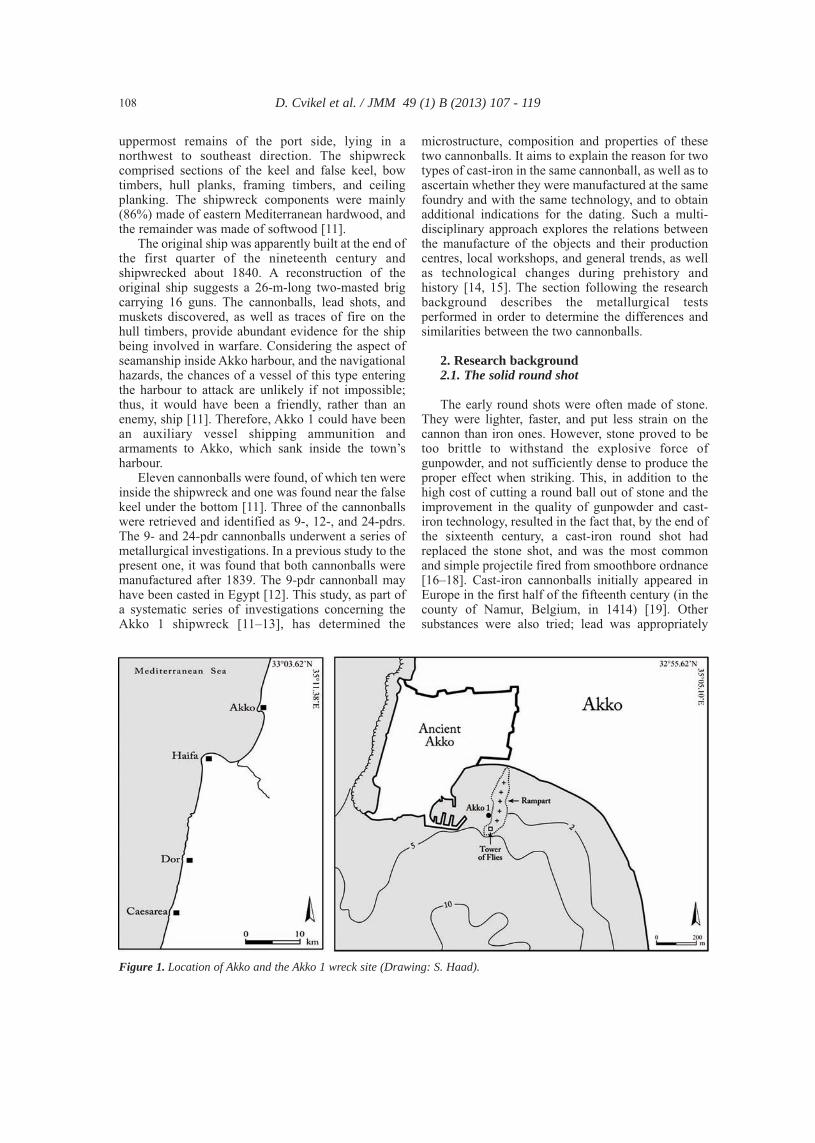
The Akko 1 shipwreck was excavated for threeseasons between 2006 and 2008 by an expedition ofthe Leon Recanati Institute for Maritime Studies at theUniversity of Haifa. The shipwreck site is inside Akkoharbour, 70 m north of ‘The Tower of Flies’, at amaximum depth of 4 m (Fig. 1). The shipwreckremains were 23 m long from bow to aft extremity,and 4.66 m wide from the line of the false keel to the
uppermost remains of the port side, lying in anorthwest to southeast direction. The shipwreckcomprised sections of the keel and false keel, bowtimbers, hull planks, framing timbers, and ceilingplanking. The shipwreck components were mainly(86%) made of eastern Mediterranean hardwood, andthe remainder was made of softwood [11].
The original ship was apparently built at the end ofthe first quarter of the nineteenth century andshipwrecked about 1840. A reconstruction of theoriginal ship suggests a 26-m-long two-masted brigcarrying 16 guns. The cannonballs, lead shots, andmuskets discovered, as well as traces of fire on thehull timbers, provide abundant evidence for the shipbeing involved in warfare. Considering the aspect ofseamanship inside Akko harbour, and the navigationalhazards, the chances of a vessel of this type enteringthe harbour to attack are unlikely if not impossible;thus, it would have been a friendly, rather than anenemy, ship [11]. Therefore, Akko 1 could have beenan auxiliary vessel shipping ammunition andarmaments to Akko, which sank inside the town’sharbour.
Eleven cannonballs were found, of which ten wereinside the shipwreck and one was found near the falsekeel under the bottom [11]. Three of the cannonballswere retrieved and identified as 9-, 12-, and 24-pdrs.The 9- and 24-pdr cannonballs underwent a series ofmetallurgical investigations. In a previous study to thepresent one, it was found that both cannonballs weremanufactured after 1839. The 9-pdr cannonball mayhave been casted in Egypt [12]. This study, as part ofa systematic series of investigations concerning theAkko 1 shipwreck [11–13], has determined the
microstructure, composition and properties of thesetwo cannonballs. It aims to explain the reason for twotypes of cast-iron in the same cannonball, as well as toascertain whether they were manufactured at the samefoundry and with the same technology, and to obtainadditional indications for the dating. Such a multi-disciplinary approach explores the relations betweenthe manufacture of the objects and their productioncentres, local workshops, and general trends, as wellas technological changes during prehistory andhistory [14, 15]. The section following the researchbackground describes the metallurgical testsperformed in order to determine the differences andsimilarities between the two cannonballs.
2. Research background2.1. The solid round shot
The early round shots were often made of stone.They were lighter, faster, and put less strain on thecannon than iron ones. However, stone proved to betoo brittle to withstand the explosive force ofgunpowder, and not sufficiently dense to produce theproper effect when striking. This, in addition to thehigh cost of cutting a round ball out of stone and theimprovement in the quality of gunpowder and cast-iron technology, resulted in the fact that, by the end ofthe sixteenth century, a cast-iron round shot hadreplaced the stone shot, and was the most commonand simple projectile fired from smoothbore ordnance[16–18]. Cast-iron cannonballs initially appeared inEurope in the first half of the fifteenth century (in thecounty of Namur, Belgium, in 1414) [19]. Othersubstances were also tried; lead was appropriately
D. Cvikel et al. / JMM 49 (1) B (2013) 107 - 119 108
Figure 1. Location of Akko and the Akko 1 wreck site (Drawing: S. Haad).
dense and less brittle than stone, but too soft;wrought-iron was very strong but difficult to workand expensive; and cast-iron united the necessaryqualities of hardness, strength, density, and cheapness[17, 18].
Iron or brass moulds, divided into two halvesfitting each other exactly, were used for theproduction of cast-iron round shots. These moulds(termed Coquilles à boulet in French), were mouldedin sand, and were made in a frame with a woodenpattern [20–22]. Later in the nineteenth century, it wasfound that iron moulds make an inferior, brittle article,liable to be easily broken, principally during the morerapid cooling of the metal. Therefore, moulds weremade of sand, similar to sand used in casting guns,although less refractory sand was needed, as the massof the metal was less, and consequently, possessedless heat. The sand was mixed with clay-water, to giveit form and consistency [17, 23].
The liquid metal was brought from the furnace ina bucket or in a ladle made of iron and coated withclay, having wrought-iron or wooden handles. It waspoured into the moulds in a small stream using afeeder, which entered the mould from the side, at thejuncture between the two halves, in order to preventinjury to the form. As the metal was raised, the airescaped through a different vent, which also served asa dead-head to collect the scoria. This vent wasvertically above the plane of the mould seam [17, 23].To produce a sound casting, additional material had tobe furnished in order to compensate for the shrinkagecaused by the cooling and solidifying metal [17, 24].
External or internal flaws could have resultedfrom the ebullitions and the interception of air. The airwould not have time to escape if the vent was filled upwith the metallic liquid. This sort of problem wasgreater in casting small calibre cannonballs since theycooled down much sooner compared with largecalibres [22].
Once taken out of the moulds, the cannonballswere imperfect, and their surface was seldom smooth.As closely joined as the moulds were, the cannonballsalmost always had a circular seam formed by themetal running out through the juncture between thetwo halves, and tearing at the fracture of the vent. Thisirregularity could have scratched the bore of thecannon. Therefore, one method to smooth thecannonball was to remove the excess metal using ahammer and a chisel. Another method was to re-heatthe shot until it became red-hot, and hammer it withmechanical hammers until it became as perfectlysmooth as possible. In some navies, severalcannonballs were later placed together in a largerevolving iron cylinder, which, by friction, polishedand made their surfaces more uniform [17, 21–23,25]. Since it was technologically impossible to cast aperfect spherical ball without any irregularities, andexactly to the diameter required, the manufacturerwas allowed a certain element of error [18, 24].
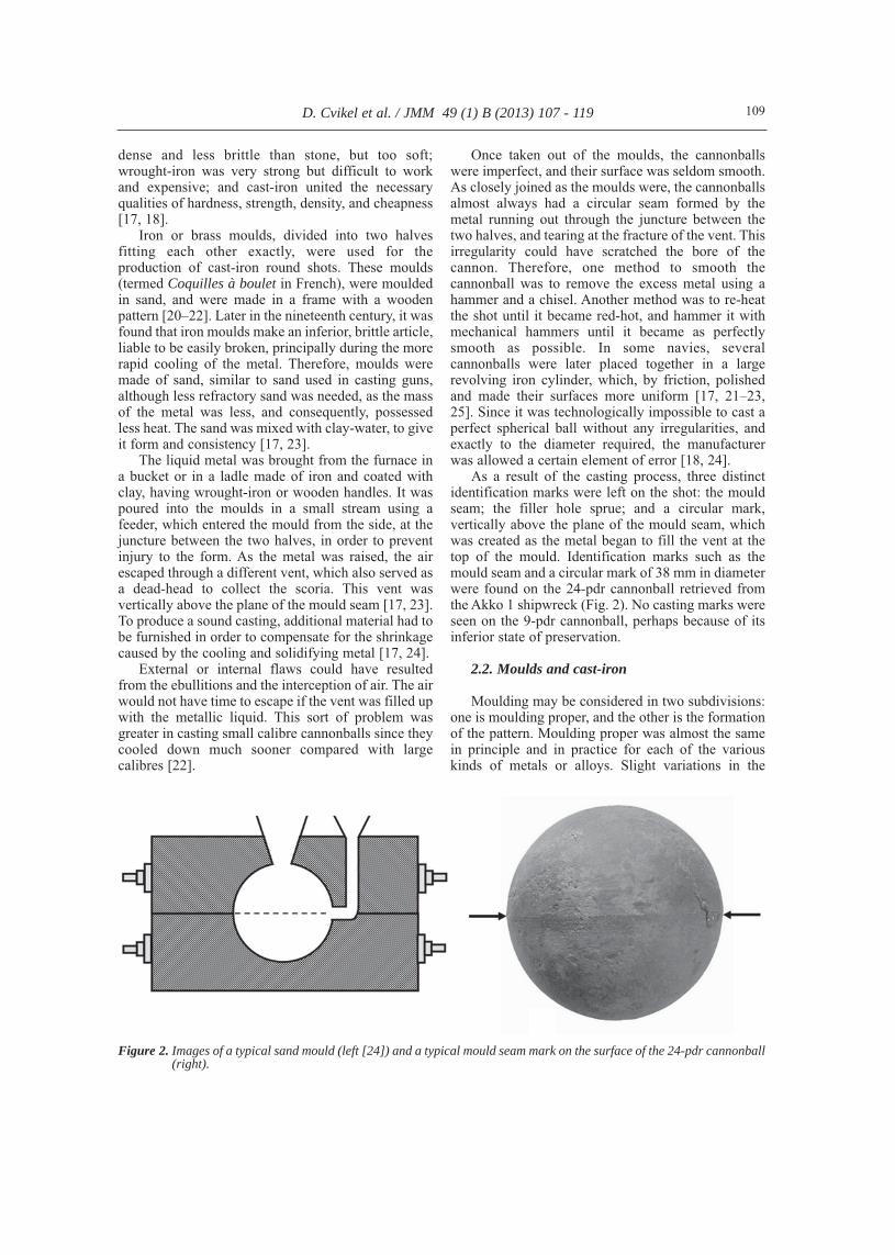
As a result of the casting process, three distinctidentification marks were left on the shot: the mouldseam; the filler hole sprue; and a circular mark,vertically above the plane of the mould seam, whichwas created as the metal began to fill the vent at thetop of the mould. Identification marks such as themould seam and a circular mark of 38 mm in diameterwere found on the 24-pdr cannonball retrieved fromthe Akko 1 shipwreck (Fig. 2). No casting marks wereseen on the 9-pdr cannonball, perhaps because of itsinferior state of preservation.
2.2. Moulds and cast-iron
Moulding may be considered in two subdivisions:one is moulding proper, and the other is the formationof the pattern. Moulding proper was almost the samein principle and in practice for each of the variouskinds of metals or alloys. Slight variations in the
D. Cvikel et al. / JMM 49 (1) B (2013) 107 - 119 109
Figure 2. Images of a typical sand mould (left [24]) and a typical mould seam mark on the surface of the 24-pdr cannonball(right).
materials for moulding and in their treatment were theonly differences in moulds which were designed to beused for metals. The principal materials used inmoulding were sand of various kinds, loam, plaster ofParis, blackening, and metal [26].
Sand was the most common, and certainly themost convenient and available material, and wasconsidered superior to all other materials formoulding [26]. As early as the Chalcolithic period,open moulds made of sand or sand and clay mixturewere used for casting copper objects [27, 28]. Sand ismore or less porous, and very refractory, so that thehot metals do not melt or bake it, two qualities of greatimportance in the successful operation of the process.The various kinds of good moulding sand employedin foundries for casting iron or brass have been foundto be of an almost uniform chemical composition,varying in grain or aggregate form only [26, 29].
Clay was frequently used for improving theadhesiveness of sand. It was selected from the whiteluminous kind, argillaceous earth, or fine clay. Theclay was either dissolved in a large quantity of water,and kept in the foundry for occasional use, or wasdried, pounded, run through a fine sieve, and thenmixed with the sand [17, 23, 26]. Moulds consistingpartly of loam or sand and partly of metal were infrequent use in iron foundries of the nineteenthcentury [26].
Cast-iron smelting was already been used in Chinasince 500 BCE (mostly gray cast-iron), but it was firstintroduced in Europe in the fifteenth century, and wasused as a raw material for blacksmiths [30–33]. TheChinese produced their low carbon iron platesindirectly from treating cast-iron by variousdecarburization processes [33]. The mass productionand use of cast-iron in Europe as an importantstructural material began in the eighteenth century inEngland when A. Darby developed a method ofsmelting iron with coked coal [30, 34, 35].
In 1810, a Swedish chemist, J. J. Berzelius,attempted to isolate silicon for the first time from itsoxide at a temperature of 1500°C by melting Si, C,and Fe in a sealed crucible [36]. Four years later, theGerman scientist K. Karsten concluded that thedifferent types of cast-iron result from different formsof carbon content [37]. During the nineteenth centurymany technical innovations were developed,including continuous melting; furnace improvements(such as better blowers and pouring devices);microscopic analysis of metals including themetallography process, developed by H. C. Sorby in1863; moulding equipment; and many other tools thatare commonly used in modern workshops andfactories [38, 39]. In 1837, a dependable mouldingmachine was introduced into the market, andcommercial mechanical blower devices entered themarket after the middle of the nineteenth century. The
nineteenth century also brought many improvementsin materials, equipment and processes, and as a result,the use of iron for castings increased significantly[40].
Cast-iron is characterized and classified accordingto its graphite percentage, shape, size andmicrostructure distribution, including ferritic,pearlitic and ferit-pearlitic matrix, and is divided intolamellar graphite cast-iron, moduler, vernicular, etc.[41]. Cast-iron contains mainly 2–4 wt% carbon (C)and mostly 0.5–3 wt% silicon (Si). Other elementswhich can be found are sulphur, phosphorus, andmanganese. Increment of carbon concentration resultsin a lower melting point of the cast [30]. Both moderngray cast-iron and the metallurgical control of metalswere inaugurated at the beginning of the nineteenthcentury (between 1810 and 1815) [30, 42]. The maindifference between gray and white cast-iron is theamount of silicon present in the alloy: gray cast-ironcontains more than 1 wt% Si, whereas white cast-ironcontains less than 1 wt% Si [43]. Since Si is a graphitestabilizing element, the addition of more than 1 wt%Si causes the C to precipitate as dark graphite flakes,surrounded by a bright pearlite matrix, and alternatingthin layers of α-ferrite and a dark cementite (Fe3C)phase [44]. The graphite formation results from aslower cooling rate solidification or according to thehigh presence of silicon in the cast-iron [37].However, a structural transition from white to graycast-iron may occur in accord with heat released andinappropriate heat treatment [41]. Cast-iron is agradient material, which means that differentmicrostructures may occur for the same compositionand the physicochemical state of molten metal as aresult of different cooling rates [45]. Parameters suchas shape and dimension of the mould and the castedobjects, the pouring temperature, and the presence ofsmall amount of different elements such as Mg, S andO, can influence the cooling rate and may causechanges in the microstructure [46]. The graphiteflakes cause low strength and ductility, but have goodmachinability and wear resistance. Less than 1 wt% Sicauses a precipitation of Fe3C particles rather thangraphite. The massive amount of cementite results ingood hardness, good abrasion resistance andbrittleness [40]. By 1860 metallurgists already knewthat gray cast-iron has good castability, a low meltingpoint (~1200oC), good fluidity, and that it is weak intension but has high strength in compression [17, 23,47]. Thermal heat treatment may improve the impactstrength of the cast-iron compared to the as-castmaterial [48]. Different manufacturing processes ofcast-iron, which varied from one foundry to another,resulted in variations in material properties [49].
Two dissimilar types of pores are formed duringcasting: the first is formed during the early stage ofsolidification, and the second is formed during the
D. Cvikel et al. / JMM 49 (1) B (2013) 107 - 119 110

last stage of the solidification process. The poreconcentration depends on factors such as thecooling rate and the carbon content [50]. Gasporosity is a significant problem, which occurs incast-iron products, and is usually caused by thedevelopment of gases during the casting process.Hydrogen and nitrogen are the common gases thatcause porosity in cast-iron. Their presence duringthe casting process may result from the reactionbetween the metallic iron and the sand mould, orfrom the development of gas bubbles, whichdissolve in the liquid metal through solidification.The solubility of hydrogen and nitrogen gasses inthe liquid metal decreases as the amount of carbonand silicon in the cast-iron increases [51].
3. Experimental methods and testing
The two cannonballs retrieved from the Akko 1shipwreck (9-pdr and 24-pdr, shown in Fig. 3) werestudied using metallographic optical microscopy(OM), scanning electron microscopy with energy-dispersive spectrometry (SEM-EDS), and hardnesstesting. The present results were compared withprevious scanning SEM-EDS and X-RayFluorescence (XRF) spectrometetry measurements[12].
Metallographic examination was performed forboth cannonballs, including cutting samples with adiamond wheel dicing saw and creating strips thatwere cut into smaller pieces. First, a rough polish wasperformed on the samples using 80 grit silicon carbide(SiC) paper. Then the samples were mounted inBakelite at a temperature of 180oC and a pressure of20 bars. Surface preparation of the specimens beganby grinding with 240–600 grit SiC papers, followedby polishing using 5–0.05 µm alumina pastes andfinally polishing using 0.05 µm colloidal silica
polishing suspension paste. After that, the sampleswere first cleaned in an ultrasonic bath to remove anycontamination, and then cleaned with ethanol anddried. Later the samples were etched with Nital acid(97 mL ethyl alcohol and 3 mL nitric acid). Afterpreparation, the samples were examined in ametallographic OM (ZEISS, AXIO Scope A.1).
SEM-EDS analysis was performed for bothcannonballs, characterized by a FEI Quanta 200FEGESEM in high vacuum mode, using the Everhart-Thonley Secondary Electron (SE) detector. Chemicalanalysis was performed using SEM-EDS with Si(Li)liquid cooled Oxford X-ray detector. Following themetallurgical examination, Rockwell C hardnessmeasurements were performed along the diameter ofboth cannonballs, with 15 N load using Future-Techhardness tester.
4. Results
Visual observation of both cannonballs revealed auniform corrosion layer at the external surface of theobject. Graphite flakes are known as sites for iron-oxide formation, so the corrosions initiate along thegraphite flake boundaries [52]. The corrosionproducts on the surface of archaeological objectsdepend on different factors, among them thecomposition and the environment in which the objectwas held, including the pH, temperature and time[53]. The metallographic OM and SEM-EDS analysisof both cannonballs, the presence of cavitiescontaining sand [12], and the seam marks on the 24-pdr shot, reveal that the 9-pdr and 24-pdr cannonballswere manufactured by sand mould casting of cast-iron. A comparison with previous SEM-EDS and X-Ray Fluorescence (XRF) spectrometetrymeasurements is shown in Tables 1 (SEM-EDS) and 2(XRF).
D. Cvikel et al. / JMM 49 (1) B (2013) 107 - 119 111
Figure 3. Images of the cannonballs after cleaning the marine encrustation: (a) 9-pdr and (b) 24-pdr (Photo: J. J.Gottlieb).
D. Cvikel et al. / JMM 49 (1) B (2013) 107 - 119 112
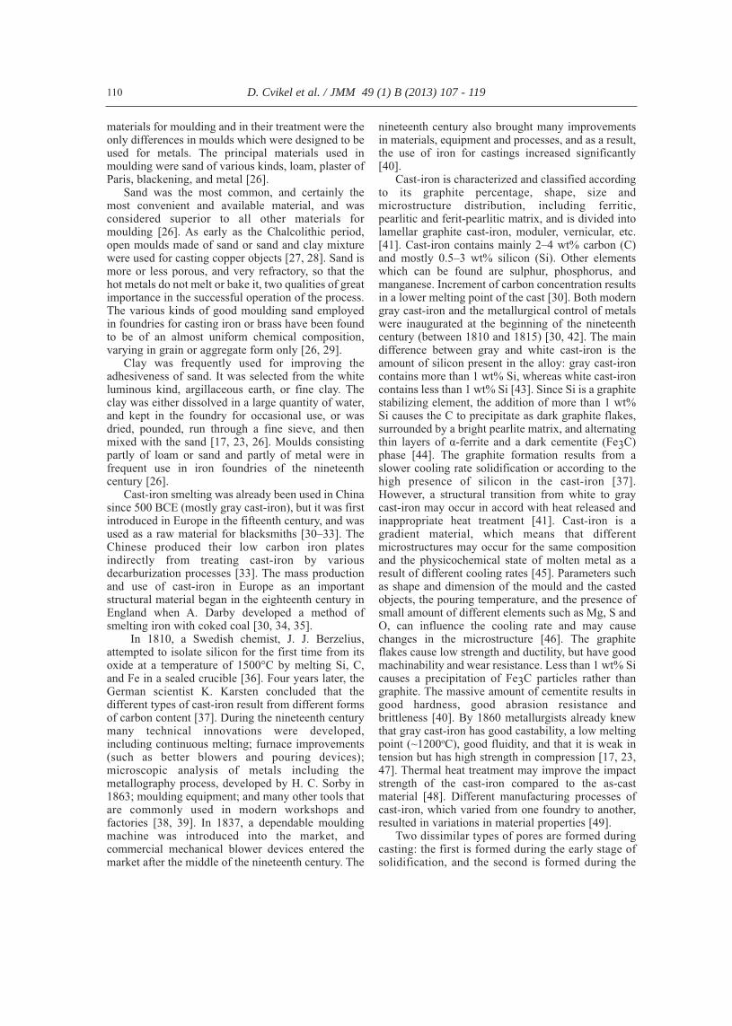
Table 1. SEM-EDS results of the cannonballs cast-iron (values in wt%), using Quanta 200 ESEM FEG from FEI.
Specimen descriptionCompositions weight
Fe C Si Mn P
The 9-pdr cannonball, white cast-iron (Fig. 4, internal part of the cannonball, area B') 96.5 2.7 – 0. 8 –
The 9-pdr cannonball, white cast-iron (Fig. 4, internal part of the cannonball, area A')[ref. 13] 95.4 3.8 – 0.8 –
The 24-pdr cannonball, gray cast-iron containing graphite flakes (Fig. 10, near externalsurface of the cannonball, area A) 96. 7 2.3 0.5 – 0.5
The 24-pdr cannonball, gray cast-iron containing graphite flakes (Fig. 10, near externalsurface of the cannonball, area B) 95.3 4.7 – – –
The 24-pdr cannonball, gray cast-iron containing graphite flakes (Fig. 10, near externalsurface of the cannonball, area A) [ref. 13] 97.4 1.3 1.3 – –
The 24-pdr cannonball, gray cast-iron, graphite flakes (Fig. 10, near external surface ofthe cannonball, area B) [ref.13] 10.2 89.8 – – –
The 24-pdr cannonball, white cast-iron (Fig. 10, internal part of the cannonball, area C,measurement 1) 95.4 3.9 – 0.7 –
The 24-pdr cannonball, white cast-iron (Fig. 10, internal part of the cannonball, area C,measurement 2) 94.6 – – 0.6 4.8
The 24-pdr cannonball, white cast-iron (Fig. 10, internal part of the cannonball, area C,measurement 3) 98.3 – 0.9 0.8 –
The 24-pdr cannonball, white cast-iron (Fig. 10, internal part of the cannonball, area C,measurement 4) 98.4 – 1.1 – 0.5
The 24-pdr cannonball, white cast-iron (Fig. 10, internal part of the cannonball, area C,measurement 5) [ref.13] 93.7 4.8 – 0.8 0.7
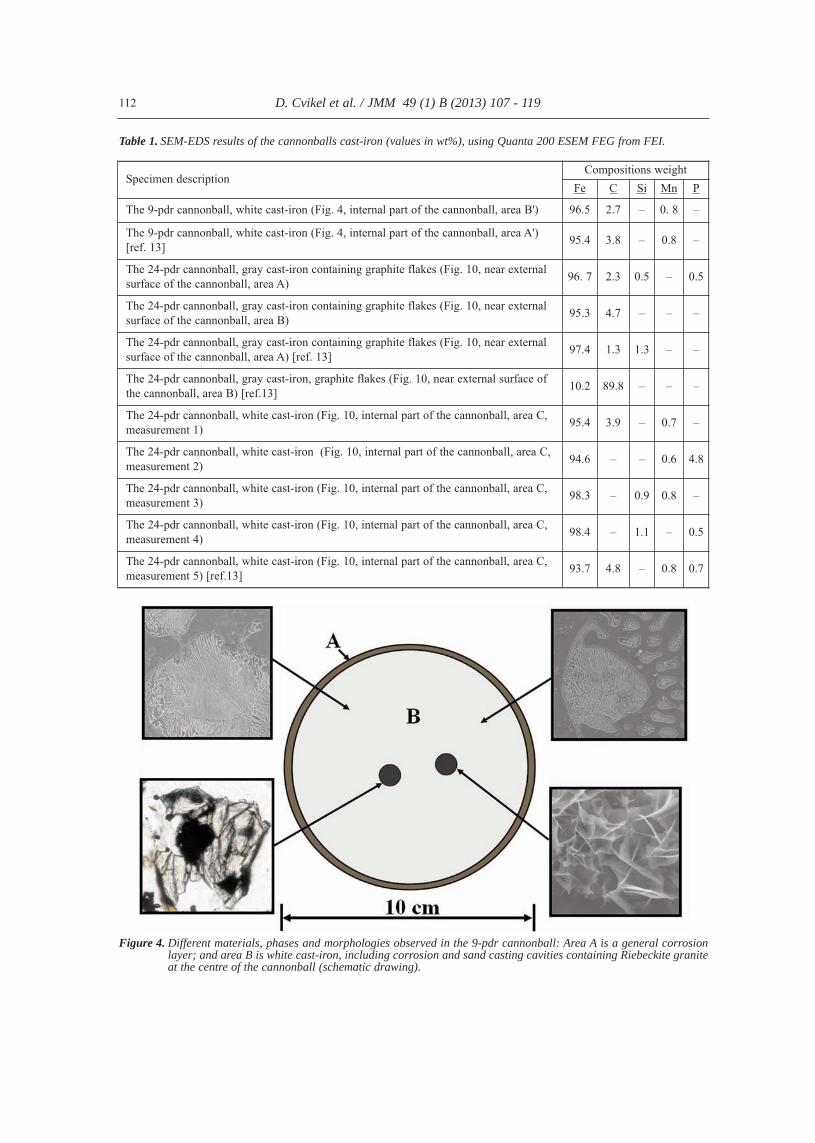
Figure 4. Different materials, phases and morphologies observed in the 9-pdr cannonball: Area A is a general corrosionlayer; and area B is white cast-iron, including corrosion and sand casting cavities containing Riebeckite graniteat the centre of the cannonball (schematic drawing).
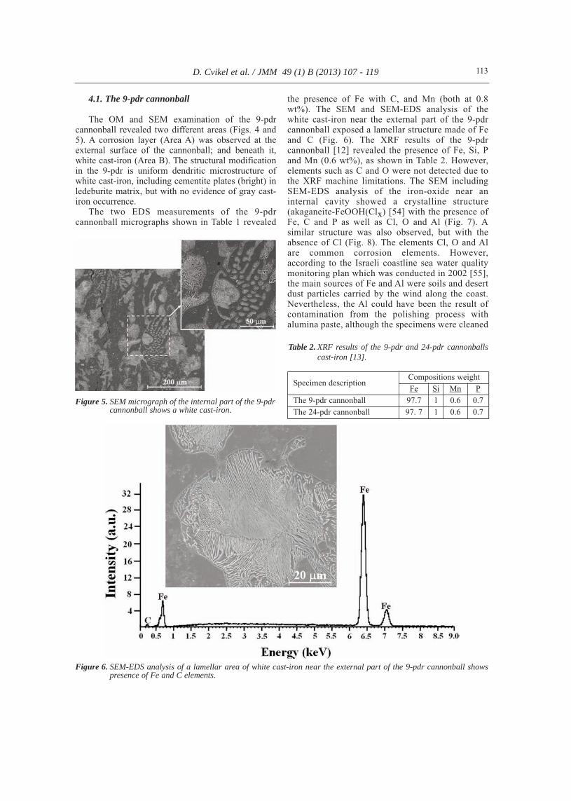
4.1. The 9-pdr cannonball
The OM and SEM examination of the 9-pdrcannonball revealed two different areas (Figs. 4 and5). A corrosion layer (Area A) was observed at theexternal surface of the cannonball; and beneath it,white cast-iron (Area B). The structural modificationin the 9-pdr is uniform dendritic microstructure ofwhite cast-iron, including cementite plates (bright) inledeburite matrix, but with no evidence of gray cast-iron occurrence.
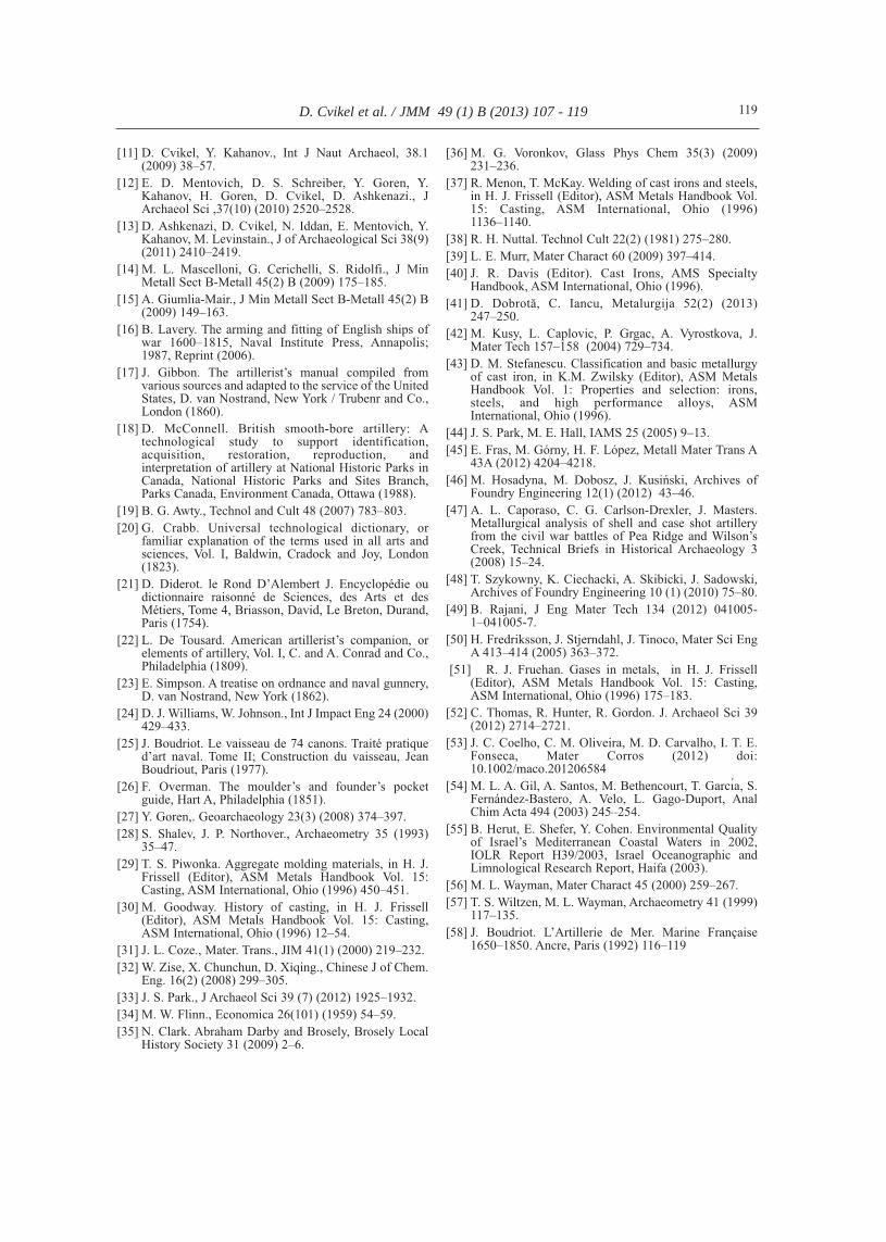
The two EDS measurements of the 9-pdrcannonball micrographs shown in Table 1 revealed
the presence of Fe with C, and Mn (both at 0.8wt%). The SEM and SEM-EDS analysis of thewhite cast-iron near the external part of the 9-pdrcannonball exposed a lamellar structure made of Feand C (Fig. 6). The XRF results of the 9-pdrcannonball [12] revealed the presence of Fe, Si, Pand Mn (0.6 wt%), as shown in Table 2. However,elements such as C and O were not detected due tothe XRF machine limitations. The SEM includingSEM-EDS analysis of the iron-oxide near aninternal cavity showed a crystalline structure(akaganeite-FeOOH(Clx) [54] with the presence ofFe, C and P as well as Cl, O and Al (Fig. 7). Asimilar structure was also observed, but with theabsence of Cl (Fig. 8). The elements Cl, O and Alare common corrosion elements. However,according to the Israeli coastline sea water qualitymonitoring plan which was conducted in 2002 [55],the main sources of Fe and Al were soils and desertdust particles carried by the wind along the coast.Nevertheless, the Al could have been the result ofcontamination from the polishing process withalumina paste, although the specimens were cleaned
D. Cvikel et al. / JMM 49 (1) B (2013) 107 - 119 113
Figure 5. SEM micrograph of the internal part of the 9-pdrcannonball shows a white cast-iron.
Figure 6. SEM-EDS analysis of a lamellar area of white cast-iron near the external part of the 9-pdr cannonball showspresence of Fe and C elements.
Table 2. XRF results of the 9-pdr and 24-pdr cannonballscast-iron [13].
Specimen descriptionCompositions weightFe Si Mn P
The 9-pdr cannonball 97.7 1 0.6 0.7The 24-pdr cannonball 97. 7 1 0.6 0.7

with an ultrasonic bath before their examination.The Rockwell hardness test results along the
diameter of the 9-pdr cannonball showed that thehardness near the external surface of the cannonballwas moderately higher than the hardness in its innerpart, as shown in Fig. 9.
4.2. The 24-pdr cannonball
The OM and SEM examination of the 24-pdrcannonball revealed three different areas (Fig. 10). Acorrosion layer (Area A) was observed at the external
D. Cvikel et al. / JMM 49 (1) B (2013) 107 - 119 114
Figure 8. SEM photography showing akaganeite-FeOOH(Clx) iron-oxide including SEM-EDS analysis at the internalcavity in the 9-pdr cannonball revealed the presence of Fe, C and P, which are typical elements of cast-iron, aswell as O and Al, which are corrosion and soil elements.
Figure 7. SEM photography showing akaganeite-FeOOH(Clx) iron-oxide including SEM-EDS analysis near the internalcavity in the 9-pdr cannonball revealed the presence of Fe, C and P, which are typical elements of cast-iron, aswell as Cl, O and Al, which are corrosion and soil elements.

surface of the cannonball; and beneath it a dendriticcast-iron microstructure, containing two differentstructures including gray (Area B) and white (Area C)cast-iron. The 24-pdr cannonball microstructure nearthe external surface was made of gray cast-ironincluding pearlite phase and graphite flakes (as shownby SEM in Fig. 11), and white cast-iron at the centreof the cannonball (Fig. 12).
The EDS analysis of the 24-pdr cannonballmicrographs (Table 1) showed the presence of Fe,C, Si, Mn and P, which are typical materials in whitecast-iron [36]. The EDS analysis of the gray cast-iron revealed the presence of Fe, C, Si and P, but noMn was observed. The EDS analysis of the whitecast-iron revealed the presence of Fe, C, P and Mn(0.8 wt% on average). At the places where P wasobserved, the surface of the metal was brighter. Atthe centre of the cannonball, sand remains werefound, probably resulting from the sand castingprocess. The XRF examination of the 24-pdr
D. Cvikel et al. / JMM 49 (1) B (2013) 107 - 119 115
Figure 9. Rockwell C hardness test results along thediameter of the 9-pdr cannonball.
Figure 10.Different materials, phases and morphologies observed in the 24-pdr cannonball: Area A is a general corrosionlayer; area B is gray cast-iron with graphite flakes; area C is white cast-iron, including corrosion and sandcasting cavities containing quartz sand at the centre of the cannonball (schematic drawing).
Figure 11. SEM micrograph near the surface of the 24-pdrcannonball shows gray cast-iron containing agraphite flake (black area).

cannonball [12] showed the presence of Fe, Si, Mn(0.6 wt%), and P (Table 2).
A SEM micrograph at the external surface of thecannonball, including EDS analysis, discloseduniform corrosion (near the gray cast-iron area).Corrosion products such as Na, Cl, O, K, Zn, Ca andAl were observed in different areas of the 24-pdrcannonball, as shown in Table 3. The SEMincluding SEM-EDS analysis of the cavity (Figs. 10and 13) observed in the bulk of the 24-pdrcannonball (a white cast-iron area) before grinding,polishing and etching, exposed crystalline structureof akaganeite-FeOOH(Clx) iron-oxide morphology(Fig. 14), which is the most common corrosionproduct of iron in a marine environment [54]. Thechloride ions are necessary materials for akaganeiteformation and stabilization. Flower-like or star-likecarbide morphology [40, 54], which is characterisedby the presence of isolated variable multi-armcarbide solidification microstructures, was alsoobserved in the 24-pdr cannonball (Fig. 15).
D. Cvikel et al. / JMM 49 (1) B (2013) 107 - 119 116
Figure 12. SEM micrograph of the internal part of the 24-pdr cannonball shows a white cast-iron.
Figure 13. SEM micrograph of the 24-pdr cannonballshows a cavity near the centre of thecannonball, which results from the sand casting
Figure 14. SEM micrograph of a cavity near the centre ofthe 24-pdr cannonball reveals akaganeite-FeOOH(Clx) iron-oxide morphology.
Table 3. SEM-EDS results of the 24-pdr cannonball at the corrosion areas (values in wt%), using Quanta 200 ESEM FEGfrom FEI.
Specimen descriptionCompositions weight percentage (wt%)
Fe C O Si Mn Na Cl K Zn Ca Al P
Gray cast-iron containing graphite flakes 77.6 8 2.1 1.4 – 4.2 4.2 0.6 1.4 – – 0.5White-iron, akaganeite akaganeite-FeOOH(Clx) 86.6 4 2.8 0.9 0.4 1.8 0.7 0.4 2 – – 0.4
White-iron, corrosion with flowers morphology 75.7 – – 1.3 – 13.2 9.2 0.6 – – – –
Gray cast-iron, general corrosion near the externalsurface of the cannonball 55. 8 23.9 13.8 2.8 0.7 – 0.3 0.4 0.9 0.4 – 1
Gray cast-iron, general corrosion near the externalsurface of the cannonball (at a cavity) 59.8 23 4.8 1.8 – – 0.5 – 7.8 0.3 1.6 0.4

The Rockwell hardness test results along thediameter of the 24-pdr cannonball showed that thehardness near the external surface of the cannonballwas significantly higher than the hardness in its innerpart (Fig. 16).
5. Discussion
A thorough study of the manufacturingtechnologies of the two cannonballs may provideinformation about the cannonballs’ date andmanufacturing location. The various tests performedon the two cannonballs were designed to determinetheir microstructure, composition and properties in
order to understand their detailed manufacturingprocess. For example, the use of a feeder in the 24-pdr cannonball in order to compensate for metalshrinkage suggests that it was manufactured duringthe first half of the nineteenth century. Thetechnological analysis may provide us withadditional information regarding manufacturingtechniques of different workshops during the firsthalf of the nineteenth century.
The sand found in the pores inside the 9-pdr and24-pdr cannonballs could not have come from theseabed environment of the shipwreck site, since thecavities were located near the centre of thecannonballs, in places where no presence ofcorrosion products was observed [12]. Therefore, it issuggested that this sand is the remains of the sandcasting.
The Rockwell hardness test, as well as the OMand SEM-EDS microscopy results along the diameterof the two cannonballs, demonstrated that they weremade of different cast-iron (see Tables 1 and 3).While the 9-pdr cannonball hardness is uniform(according to its uniform structure), as shown in Fig.9, the 24-pdr cannonball is non-homogeneousaccording to its non-uniform gray and white cast-ironstructure, as shown in Fig. 16, with higher hardnessnear the external surface of the cannonball.
The fact that the two cannonballs are different interms of their microstructure and their hardnessdistribution could result from two dissimilarprocesses:
(a) The casting of the 9-pdr cannonball was madein one step, without the use of a feeder and withoutany feeding of additional molten material. Therefore,the white cast-iron is present in all parts of thecannonball including the external part, where the heatremoval rate is higher [37].
(b) In the 24-pdr cannonball gray cast-iron ispresent only in the external part of the cannonball,while white cast-iron is present in the internal part.Therefore, it may be assumed that in the 24-pdrcannonball the liquid material of the white cast-ironwas poured into the casting mould first, and only thenwas the liquid material of the gray cast-iron poured inusing a feeder.
The addition of liquid material (gray cast-iron)into the sand mould during the solidification,apparently results from the need to close spacesinside the bulk of the cannonball and thereby reduceporosity to the minimum. It is also possible that theuse of gray cast-iron was intended to ameliorate thehardness and wear resistance of the external surfaceof the 24-pdr cannonball. This may indicates thatduring the period of the cannonballs’ manufacture, itwas already known that the presence of porosity in acannonball could result in a reduction of their targetfiring capability. Adding manganese to both
D. Cvikel et al. / JMM 49 (1) B (2013) 107 - 119 117
Figure 15. SEM micrograph of a cavity near the centre ofthe 24-pdr cannonball shows flower-like or star-like morphology.
Figure 16. Rockwell C hardness test results along thediameter of the 24-pdr cannonball.

cannonballs during solidification results in reducinggas holes and porosity [12, 56, 57], which probablyimproved firing capabilities. The importance of usinga feeder in the 24-pdr cannonball results from the factthat the bigger the mould is, the larger the shrinkageproblem caused during solidification [24].
Shell guns were introduced in 1837 [58]. The factthat only cannonballs were found in the shipwreck,might indicate at a pre-1837 dating. However,cannonballs were still in use during the Crimean War(1854–1856) [58]. Considering that the introductionof modern gray cast-iron occurred at the beginning ofthe nineteenth century (between 1810 and 1815) [30,42], combined with the presence of gray cast-iron inthe 24-pdr cannonball, suggest that the twocannonballs were casted during the first half of thenineteenth century. It seems that they were notmanufactured post-1860, since at that time thequalities of gray cast-iron were already known [17,23, 47], and the use of white cast-iron was less likely.Thus, the casting of the cannonballs could have takenplace between about 1810 and not later than 1860.This is supported by the relatively high concentrationof manganese in both cannonballs, since the presenceof more than 0.1 wt% Mn means that the manganesewas added deliberately into the alloy and designatesa post-1839 manufacture date [12, 56]. Therefore, themanufacturing technologies presented in this study,reinforce the possible dating of the two cannonballs.
Considering the metallurgical and chemicalcomposition analysis, the naval context of Akko 1shipwreck, and the fact that no naval campaign tookplace in the Akko vicinity after 1840, it is suggestedthat the Akko 1 shipwreck could have taken part inthe battle of 1840 and sank. However, its being anauxiliary vessel that entered Akko harbour withammunition and supply a short while earlier or evenlater than 1840 is no less logical. The approximate1840 or earlier dating reinforces the assumption thatit was a ship friendly to the Egyptian forcescontrolling Akko at that time [11].
6. Conclusions
The two cannonballs retrieved from the Akko 1shipwreck were made of cast-iron and manufacturedby sand casting moulds. The fact that the cast-iron inthe 24-pdr cannonball is non-uniform might indicatethe use of a feeder in order to compensate for metalshrinkage during the cooling process, and wasperhaps also done in order to improve the hardnessand wear resistance of the external surface of the 24-pdr cannonball. The different manufacturing processobserved on the two cannonballs, suggest that theywere manufactured by two different technologies atthe same foundry, or in different foundries and withdifferent technologies. The latter may support the
possibility that they belonged to different navies. Thecannonballs were apparently manufactured about theend of the first half of the nineteenth century, andconsidering the archaeological and historicalbackground, this may reinforce the suggestion thatAkko 1 was a naval auxiliary brig which was in Akkoharbour about 1840.
Acknowledgements
The underwater excavations and research of theAkko 1 shipwreck have been supported by RonMarlar, the Yaacov Salomon Foundation, ReuvenSadnai—Coral Maritime Services Ltd., the HalpernFoundation, the Sir Maurice Hatter Fellowship,Hecht Trust, the Jewish National Fund Fellowship,the President, Rector, Dean and Faculty ofHumanities, University of Haifa, and anonymousdonors, to whom the authors are most grateful.The authors would also like to thank Rudi Roth,
artillery historian, for his valuable insights andadvice; and Barbara Doron for the English editing.Further thanks are due to Mario Levinstein andDavid Schreiber from the School of MechanicalEngineering at Tel Aviv University for theirassistance.
References
[1] M. Dothan. Tell Acco, in: E. Stern (Editor), The newencyclopedia of archaeological excavations in the HolyLand, Vol. 1, Israel Exploration Society, Carta,Jerusalem (1993) 17–24.
[2] N. Makhouly, C. N. Johns. Guide to Acre, Governmentof Palestine. Department of Antiquities, Jerusalem(1946).
[3] A. Negev, S. Gibson (Eds.). ArchaeologicalEncyclopedia of the Holy Land. Continuum, NewYork/London (2005).
[4] A. Raban. The Harbours of Akko, in M. Yedaya(Editor), The western Galilee antiquities, Ministry ofDefence Publishing, Tel Aviv (1986) 180–189 (inHebrew).
[5] B. Masters. Acre, in G. Ágoston, B. Masters (Editors),Encyclopedia of the Ottoman Empire, Facts on File,New York (2009) 9–10.
[6] R. C. Anderson. Notes on Acre and some of the coastdefences in Syria (papers on subjects connected withthe duties of the Corps of Royal Engineers, VI), JohnWeale, London (1843).
[7] R. C. Anderson. Naval wars in the Levant 1559–1853.University Press of Liverpool, Liverpool (1952).
[8] C. La Jonquière. L`Expédition d`Egypte, 1798–1801,H. Charles-Lavauzelle, Paris (1900).
[9] A. J. Rustum, Notes on Akka and its defences underIbrahim Pasha. American University of Beirut, Beirut(1926).
[10] G. E. Durand-Viel. Les campagnes navales deMohammed Aly et d’Ibrahim, Vol. II, ImprimerieNational, Paris (1935).
D. Cvikel et al. / JMM 49 (1) B (2013) 107 - 119 118
[11] D. Cvikel, Y. Kahanov., Int J Naut Archaeol, 38.1(2009) 38–57.
[12] E. D. Mentovich, D. S. Schreiber, Y. Goren, Y.Kahanov, H. Goren, D. Cvikel, D. Ashkenazi., JArchaeol Sci ,37(10) (2010) 2520–2528.
[13] D. Ashkenazi, D. Cvikel, N. Iddan, E. Mentovich, Y.Kahanov, M. Levinstain., J of Archaeological Sci 38(9)(2011) 2410–2419.
[14] M. L. Mascelloni, G. Cerichelli, S. Ridolfi., J MinMetall Sect B-Metall 45(2) B (2009) 175–185.
[15] A. Giumlia-Mair., J Min Metall Sect B-Metall 45(2) B(2009) 149–163.
[16] B. Lavery. The arming and fitting of English ships ofwar 1600–1815, Naval Institute Press, Annapolis;1987, Reprint (2006).
[17] J. Gibbon. The artillerist’s manual compiled fromvarious sources and adapted to the service of the UnitedStates, D. van Nostrand, New York / Trubenr and Co.,London (1860).
[18] D. McConnell. British smooth-bore artillery: Atechnological study to support identification,acquisition, restoration, reproduction, andinterpretation of artillery at National Historic Parks inCanada, National Historic Parks and Sites Branch,Parks Canada, Environment Canada, Ottawa (1988).
[19] B. G. Awty., Technol and Cult 48 (2007) 783–803.[20] G. Crabb. Universal technological dictionary, or
familiar explanation of the terms used in all arts andsciences, Vol. I, Baldwin, Cradock and Joy, London(1823).
[21] D. Diderot. le Rond D’Alembert J. Encyclopédie oudictionnaire raisonné de Sciences, des Arts et desMétiers, Tome 4, Briasson, David, Le Breton, Durand,Paris (1754).
[22] L. De Tousard. American artillerist’s companion, orelements of artillery, Vol. I, C. and A. Conrad and Co.,Philadelphia (1809).
[23] E. Simpson. A treatise on ordnance and naval gunnery,D. van Nostrand, New York (1862).
[24] D. J. Williams, W. Johnson., Int J Impact Eng 24 (2000)429–433.
[25] J. Boudriot. Le vaisseau de 74 canons. Traité pratiqued’art naval. Tome II; Construction du vaisseau, JeanBoudriout, Paris (1977).
[26] F. Overman. The moulder’s and founder’s pocketguide, Hart A, Philadelphia (1851).
[27] Y. Goren,. Geoarchaeology 23(3) (2008) 374–397. [28] S. Shalev, J. P. Northover., Archaeometry 35 (1993)
35–47.[29] T. S. Piwonka. Aggregate molding materials, in H. J.
Frissell (Editor), ASM Metals Handbook Vol. 15:Casting, ASM International, Ohio (1996) 450–451.
[30] M. Goodway. History of casting, in H. J. Frissell(Editor), ASM Metals Handbook Vol. 15: Casting,ASM International, Ohio (1996) 12–54.
[31] J. L. Coze., Mater. Trans., JIM 41(1) (2000) 219–232. [32] W. Zise, X. Chunchun, D. Xiqing., Chinese J of Chem.
Eng. 16(2) (2008) 299–305.[33] J. S. Park., J Archaeol Sci 39 (7) (2012) 1925–1932. [34] M. W. Flinn., Economica 26(101) (1959) 54–59.[35] N. Clark. Abraham Darby and Brosely, Brosely Local
History Society 31 (2009) 2–6.
[36] M. G. Voronkov, Glass Phys Chem 35(3) (2009)231–236.
[37] R. Menon, T. McKay. Welding of cast irons and steels,in H. J. Frissell (Editor), ASM Metals Handbook Vol.15: Casting, ASM International, Ohio (1996)1136–1140.
[38] R. H. Nuttal. Technol Cult 22(2) (1981) 275–280.[39] L. E. Murr, Mater Charact 60 (2009) 397–414.[40] J. R. Davis (Editor). Cast Irons, AMS Specialty
Handbook, ASM International, Ohio (1996).[41] D. Dobrotă, C. Iancu, Metalurgija 52(2) (2013)
247–250. [42] M. Kusy, L. Caplovic, P. Grgac, A. Vyrostkova, J.
Mater Tech 157–158 (2004) 729–734.[43] D. M. Stefanescu. Classification and basic metallurgy
of cast iron, in K.M. Zwilsky (Editor), ASM MetalsHandbook Vol. 1: Properties and selection: irons,steels, and high performance alloys, ASMInternational, Ohio (1996).
[44] J. S. Park, M. E. Hall, IAMS 25 (2005) 9–13.[45] E. Fras, M. Górny, H. F. López, Metall Mater Trans A
43A (2012) 4204–4218.[46] M. Hosadyna, M. Dobosz, J. Kusiński, Archives of
Foundry Engineering 12(1) (2012) 43–46.[47] A. L. Caporaso, C. G. Carlson-Drexler, J. Masters.
Metallurgical analysis of shell and case shot artilleryfrom the civil war battles of Pea Ridge and Wilson’sCreek, Technical Briefs in Historical Archaeology 3(2008) 15–24.
[48] T. Szykowny, K. Ciechacki, A. Skibicki, J. Sadowski,Archives of Foundry Engineering 10 (1) (2010) 75–80.
[49] B. Rajani, J Eng Mater Tech 134 (2012) 041005-1–041005-7.
[50] H. Fredriksson, J. Stjerndahl, J. Tinoco, Mater Sci EngA 413–414 (2005) 363–372.
[51] R. J. Fruehan. Gases in metals, in H. J. Frissell(Editor), ASM Metals Handbook Vol. 15: Casting,ASM International, Ohio (1996) 175–183.
[52] C. Thomas, R. Hunter, R. Gordon. J. Archaeol Sci 39(2012) 2714–2721.
[53] J. C. Coelho, C. M. Oliveira, M. D. Carvalho, I. T. E.Fonseca, Mater Corros (2012) doi:10.1002/maco.201206584
[54] M. L. A. Gil, A. Santos, M. Bethencourt, T. Garcıa, S.Fernández-Bastero, A. Velo, L. Gago-Duport, AnalChim Acta 494 (2003) 245–254.
[55] B. Herut, E. Shefer, Y. Cohen. Environmental Qualityof Israel’s Mediterranean Coastal Waters in 2002,IOLR Report H39/2003, Israel Oceanographic andLimnological Research Report, Haifa (2003).
[56] M. L. Wayman, Mater Charact 45 (2000) 259–267.[57] T. S. Wiltzen, M. L. Wayman, Archaeometry 41 (1999)
117–135.[58] J. Boudriot. L’Artillerie de Mer. Marine Française
1650–1850. Ancre, Paris (1992) 116–119
D. Cvikel et al. / JMM 49 (1) B (2013) 107 - 119 119