Cassini Radar BODP SIS - NASA
102
DORA-001 Cassini Radar Instrument Team Cassini Radar Burst Ordered Data Products SIS Version 2.0 Bryan Stiles May 1, 2008 Jet Propulsion Laboratory California Institute of Technology NASA D-27891
Transcript of Cassini Radar BODP SIS - NASA

DORA-001
Cassini Radar Instrument Team
Cassini Radar Burst Ordered Data Products SIS Version 2.0
Bryan Stiles
May 1, 2008 Jet Propulsion Laboratory California Institute of Technology NASA D-27891


2008/06/25 Cassini RADAR Burst Ordered Data Products SIS, Version 2.0 ii
Document Log
Revision Date
Revised Pages Description Revised By
02/28/2004 All Original. B. Stiles
03/15/2004 14, 39, 77,78
Added num_bursts_in_flight data field to engineering data segment to handle a special case used in distant scatterometry.
B. Stiles
02/28/2005 14,15, 18,
26, 30, 43,79,103
Added mention that product_id is file name without extension to Table 5. Changed definition of t_sc_clock in intermediate data segment. Cleaned up various typos. Removed "processable bit" (bit 6) of engineer_qual_flag as it was redundant. Explained that spacecraft clock counts are not exactly one second. Added a RINGS target. Provided more details on when science data segment fields will be archived. Modified PRODUCER_FULL_NAME and PRODUCER_INSTITUTION_NAME values. Set data types of altimeter_profile_range_start and altimeter_profile_range_step to real32 in the Appendix. Now they agree with the start byte table.
B. Stiles
05/16/2005 Signature page, 14,
15,23,26,30
Removed PDS program manager for signature page, Removed DATA_TAKE_NO keyword from labels. Documented two unusual data cases 1) Compressed Scatterometer Mode, 2) Radio frequency source scans.
B. Stiles
06/27/2005 34 Corrected erroneous SBDR record length of 1204 bytes to the correct length of 1273 bytes. B. Stiles
06/29/2005 24,34 Corrected inaccurate reference to DOM to TDS, SBDR record length is 1272 bytes. (1273 is start byte of echo data)
B. Stiles
09/27/2005 21,26,30, 42,99,103
Slight modification to filename and PRODUCT_ID format. Altimeter data field name and definition changed to height_above_surface from range_to_target. Minor typos corrected.
B. Stiles
12/19/2007 All Reformatted from FrameMaker into Word P. Callahan
03/12/2008 Appendix D
Added Altimeter ASCII Product material. Updated discussion of altimeter data. Changed height_above_surface to surface_height; has_std to surf_ht_std. Additional minor revisions, formatting.
P. Callahan
04/04/2008 Appendix D Clarified definitions of uncorrected and corrected surface height. P. Callahan
04/18/2008 10 Clarified definitions and use of time offset variables. P. Callahan
05/01/2008 All
Changed document properties and formatting of last figure to correct problems when exporting to HTML. Also corrected numerous formatting problems. Fixed various items found in PDS review
J. Shimada, P. Callahan

2008/06/25 Cassini RADAR Burst Ordered Data Products SIS, Version 2.0 iii
Table of Contents 1 INTRODUCTION ...................................................................................................................1
1.1 Purpose and Scope.................................................................................................................... 1 1.2 Applicable Documents (References) ....................................................................................... 1 1.3 Relationships with Other Interfaces......................................................................................... 2
2 DATA PRODUCT CHARACTERISTICS AND ENVIRONMENT ........................................... 2 2.1 Instrument Overview.................................................................................................................. 2 2.2 Instrument Description Summary ............................................................................................ 3 2.3 Data Products Description........................................................................................................ 3
2.3.1 Engineering Data Segment ............................................................................................... 5 2.3.2 Intermediate Level Data Segment..................................................................................... 6 2.3.3 Science Data Segment.................................................................................................... 10 2.3.4 Sampled Echo Data......................................................................................................... 15 2.3.5 Altimeter Profile ............................................................................................................... 15
2.4 Data Processing....................................................................................................................... 16 2.4.1 Data Product Generation................................................................................................. 16 2.4.2 Science Processing and Calibration Algorithms.............................................................. 16 2.4.3 Data Flow......................................................................................................................... 16 2.4.4 Labeling and Identification............................................................................................... 17
2.5 Standards Used in Generating Data Products...................................................................... 19 2.5.1 Coordinate Systems ........................................................................................................ 19 2.5.2 PDS Standards................................................................................................................ 20 2.5.3 Data Storage Conventions .............................................................................................. 20
2.6 Data Validation ......................................................................................................................... 20
3 APPLICABLE PDS SOFTWARE TOOLS........................................................................... 20
4 APPENDIX A EXAMPLE LBDR PDS LABEL .................................................................... 21
5 APPENDIX B.1: PARTIAL CONTENTS OF SBDR.FMT.................................................... 23
6 APPENDIX B.2: CONTENTS OF LBDR.FMT .................................................................... 24
7 APPENDIX: B.3 CONTENTS OF ABDR.FMT .................................................................... 24
8 APPENDIX C: DETAILED DESCRIPTION OF FIELDS IN SBDR RECORD ..................... 25 8.1 SBDR Start Byte Table ............................................................................................................ 25 8.2 List of SBDR Field Descriptions............................................................................................. 32
8.2.1 Engineering Data Segment Fields................................................................................... 32 8.2.2 Intermediate Level Data Segment Fields ........................................................................ 65 8.2.3 Science Data Segment Fields ......................................................................................... 77
9 APPENDIX D: ABDR SUMMARY FILE (ASCII CSV)........................................................ 89

2008/06/25 Cassini RADAR Burst Ordered Data Products SIS, Version 2.0 1
1 INTRODUCTION
1.1 Purpose and Scope The purpose of this Data Product Software Interface Specification (SIS) is to provide users
of the Cassini Burst Ordered Data Products (BODP) with a detailed description of the products and a description of how they were generated. Cassini Burst Ordered Data Products are data sets at various stages of processing which are organized as time-ordered records for each burst. The products described in this SIS are listed in Table 1, Cassini Burst Order Data Products.
Table 1: Cassini Radar Burst Ordered Data Products
Data Set ID Name Description
CO-V/E/J/S-RADAR-3-SBDR-V1.0
Short Burst Data Records
Instrument Telemetry and Calibrated Science Data in Burst Order. Excludes time sampled echo data and altimeter profiles.
CO-V/E/J/S-RADAR-3-LBDR-V1.0
Long Burst Data Records
Same as SBDR but includes time sampled echo data.
CO-SSA-RADAR-3-ABDR-V1.0
Altimetry Burst Data Records
Same as SBDR but includes altimeter profiles. Only covers time periods in Altimeter mode.
CO-SSA-RADAR-3-ABDR-SUMMARY-V1.0
Altimetry Burst Data Summary
Additional information extracted from altimeter profiles. Only covers time periods in Altimeter mode.
This SIS is intended to provide enough information to enable users to read and understand
the Cassini Burst Ordered Data Products. This SIS is intended for software developers, engineers, and scientists interested in accessing and using these products.
This Data Product SIS describes how Cassini Radar Burst Ordered Data Products were processed, formatted, labeled, and uniquely identified. The document discusses standards used in generating the product and software that may be used to access the product. The data product structure and organization is described in sufficient detail to enable a user to read the product.
A description of the BODP product formats and the data contained in them is provided in Section 2.3 – Data Products Description. This description is at a level of detail, which we expect to be useful for the majority of users. For examples of PDS labels (headers) see Appendices A and B. For a detailed description of all the data fields in the BODP products and a table of their locations in the file see Appendix C. The length of records can also be found in Appendix C as well as in the attached PDS label of each BODP file.
1.2 Applicable Documents (References) This Data Product SIS is responsive to the following Cassini documents: 1) Project Data Management Plan, JPL D-12560, PD 699-061, Rev. B, April 1999, and
Science Management Plan, JPL D-9178, PD 699-006, July 1999. 2) Cassini RADAR Basic Image Data Records SIS, JPL D-27889, Feb 2004, Version 1.0. 3) Cassini/Huygens Archive Plan for Science Data, JPL D-15976, 699-068. 4) SIS for Cassini RADAR Digital Map Products, JPL D-xxxx, Version 1.0
2008/06/25 Cassini RADAR Burst Ordered Data Products SIS, Version 2.0 2
This SIS is also consistent with the following Planetary Data System documents: 5) Planetary Data System Data Preparation Workbook, Version 3.1, February 17, 1995,
JPL D-7669, Part 1. 6) Planetary Data System Data Standards Reference, June 15, 2001, Version 3.4,
JPL D-7669, Part 2. 7) SIS for Cassini Radar Basic Image Data Records, JPL Document #D-27889 8) Volume SIS for Cassini Radar Digital Map Products, JPL Document #D-30412, USGS
#IO-AR-014 9) SIS for Cassini Radar Digital Map Products, JPL Document #D-30411, USGS
#IO-AR-015 10) Volume SIS for Cassini Radar Instrument Team Data Products, Document # D-27890 Finally, this SIS is meant to be consistent with the contract negotiated between the Cassini
Project and the Cassini RADAR Experiment Principal Investigator (PI) in which data products and documentation are explicitly defined as deliverable products.
1.3 Relationships with Other Interfaces There are two other data product sets that contain data from the Cassini Radar instrument.
These are: the Basic Image Data Records (BIDR) and the Digital Map Products (DMP). Both of these product sets are downstream from the data products described in this
document. The Cassini Radar Instrument team is responsible for developing and documenting the BIDR data. See SIS [7].
The document that describes the volume which contains BODP and BIDR data is [10]. Randolph Kirk of the US Geological Survey is responsible for developing and documenting
the DMP data. The relevant SIS's are [8] and [9].
2 DATA PRODUCT CHARACTERISTICS AND ENVIRONMENT
2.1 Instrument Overview The Cassini RADAR is a facility instrument on the Cassini Orbiter. It is capable of passive
(radiometer) and active (scatterometer, altimeter, SAR imaging) operation. During active mode operation interleaved passive measurements are also obtained.
The primary target for Cassini Radar observations is Titan, the largest Saturnian moon. Due to its thick hazy atmosphere, Titan's surface was not imaged successfully by the Pioneer or Voyager spacecraft, though atmospheric "windows" in the near infrared have been exploited by the Hubble Space Telescope and earth-based telescopes to produce low-resolution albedo maps of part of the surface. The Cassini radar instrument will obtain backscatter and altimeter sounding measurements of portions of Titan's surface. High resolution synthetic aperture radar (SAR) backscatter images of 15% of Titan's surface will be obtained. Radiometer measurements covering the entire surface of Titan will also be acquired.

2008/06/25 Cassini RADAR Burst Ordered Data Products SIS, Version 2.0 3
2.2 Instrument Description Summary Instrument Type: Radar Modes:
Imaging (13.78 GHz; 0.425 MHz & 0.85 MHz bandwidth) Altimeter (13.78 GHz; 4.25 MHz bandwidth) Scatterometer (13.78 GHz; 0.1 MHz bandwidth) Radiometer (13.78 GHz; 135 MHz bandwidth)
Number of nominal Operational Periods: One (1) per selected flyby of Titan (approximately 12 to 22 flybys, total)
Duration of nominal Operational Period: From 300 minutes before to 300 minutes after closest approach to Titan for prime operation.
Peak Power: 86 W Data Rates:
1 kbps: Radiometer only 30 kbps: Altimeter & Scatterometer / Radiometer 365 kbps: SAR Imaging / Radiometer
2.3 Data Products Description This document describes the data included in the Burst Ordered Data Products. Burst
Ordered Data Products (BODP) are comprehensive data files that include engineering telemetry, radar operational parameters, raw echo data, instrument viewing geometry, and calibrated science data. The BODP files contain time-ordered fixed length records. Each record corresponds to the full set of relevant data for an individual radar burst. The Cassini Radar is operated in "burst mode", which means the radar transmits a number of pulses in sequence then waits to receive the return signals. "Burst" is a descriptive term for the train of pulses transmitted by the radar. We use the term "burst" (somewhat unconventionally) to refer to an entire measurement cycle including transmit, receipt of echo, and radiometric (passive) measurements of the naturally occurring radiation emitted from the surface. In fact, even when the transmitter is turned off and only passive measurements are made we still refer to the measurement cycle as a burst.
Burst Ordered Data Products are fixed header length, fixed record length files. The header is an attached PDS label. See Section 2.4.4 – Labeling and Identification for a description of BODP attached PDS labels and Appendix A and B for examples. Records are rows in a table. Each data field is a column. All one needs to know to read a particular data value from a particular data field is the header length, the record size, and the byte offset of the data field within the record. Since a UTC time tag is included in each record, it is a simple matter to restrict the data one reads to a particular time interval. In order to further facilitate temporal segmentation of the data, we plan to provide a Cassini Radar Transition (CRT) file for each Titan pass. This file will maintain a temporally ordered list of the times and transition types for all scan start and end events, and radar mode transitions (e.g., radiometry to scatterometry mode switch). See the Volume SIS for more information about CRT file formats.
The BODP comprise three separate similar data sets, including the Short Burst Data Record (SBDR) the Long Burst Data Record (LBDR) and the Altimeter Burst Data Record (ABDR) plus the ABDR Summary file. The only difference among the first three formats is whether or not two data fields are included: the sampled echo data, and the altimeter profile.

2008/06/25 Cassini RADAR Burst Ordered Data Products SIS, Version 2.0 4
The altimeter profile is an intermediate processing result between sampled echo data and a final surface height estimate. LBDRs include the echo data but not the altimeter profile. ABDRs include the altimeter profile but not the echo data. SBDRs include neither. Note that the ABDR and ABDR Summary files only cover time periods when the instrument is in altimetry mode (e.g., bandwidth). These trivial differences necessitate different data sets because the two fields in question are much larger than all the other data fields combined. The majority of the bursts in a typical Titan pass are passive measurements. These bursts do not produce echo data or altimeter profiles. Of the active mode bursts most are not in altimeter mode so no altimeter profiles are produced. Including these two data fields when they are invalid would ridiculously increase the size of the archived data. The alternative of having variable length records was deemed to overly complicate data archiving and analysis procedures. Maintaining three data sets reduces data volume while allowing record lengths to remain fixed. The ABDR Summary file is an ASCII comma-separated value file that provides additional information derived from the altimeter profile. The ABDR Summary file is an addition to Version 2 of the data and is described in Appendix D.
Consider a typical Titan pass. When approaching Titan, first only radiometer measurements are obtained. Then the transmitter is turned on and scatterometer measurements are added. When Titan is close enough for useful altimetry, the radar goes into altimeter mode. Finally, about 15 minutes prior to closest approach SAR observation begins. On the outbound portion of the pass these transitions occur in reverse. When the data from a pass is received on the ground, it is processed in the following manner: An SBDR record is produced for every burst throughout the pass. An LBDR file is produced which only contains records for the middle portion of the pass during which the transmitter was on. (Sometimes it is necessary to create multiple LBDR files in order to avoid file lengths > 2Gbytes which are problematic for older operating systems.) An ABDR file is produced which contains records for only the periods (typically one inbound, one outbound) in which the radar is in altimeter mode. If desired, bursts can be easily matched across data sets. One data field in each record is a burst identifier, which uniquely distinguishes a burst from all other bursts in the mission. Records in different data sets that correspond to the same burst have the same burst ID.
Excepting unitless quantities and raw telemetry, all data fields are stored in standard units: 1 time in seconds 2 frequency in Hertz 3 power in Watts 4 current in Amps 5 voltage in Volts 6 length in kilometers 7 temperature in Kelvin 8 angles in degrees 9 velocity in kilometers per second 10 angular velocity in degrees per second 11 energy in Joules The SBDR data record is divided into three consecutive segments from three different
levels of processing: 1) the engineering data segment, 2) the intermediate level data segment (mostly spacecraft geometry), and 3) the science data segment (antenna temperature, backscatter, measurement geometry, etc.). Below, in Sections 2.3.1 – 2.3.3, we describe a subset of the fields in each of these data segments which is likely to be of interest to the average

2008/06/25 Cassini RADAR Burst Ordered Data Products SIS, Version 2.0 5
user. The engineering data segment contains a complete copy of the telemetry data downlinked from the spacecraft and thus has the most fields by far. It includes temperatures, instrument instructions, operational parameters of the radar, and raw measurements (i.e., unnormalized radiometer counts.) For the sake of conciseness, we avoid discussing many of these fields here. For a full description of all SBDR fields see Appendix C. In Section 2.3.4 we describe the raw active mode data, and in Section 2.3.5 we describe the altimeter profile.
2.3.1 Engineering Data Segment The engineering data segment includes a copy of the radar telemetry contained in the
Engineering Ground Support Equipment (EGSE) files obtained from the spacecraft data downlinks. This data is stored to allow investigators to access as much of the information obtained by the spacecraft as possible. Telemetry data is decoded and converted to standard units. The most important fields in this segment are the radar operational parameters and the raw radiometer data. The following table documents each of these fields. Each field in the table is 4 bytes long.
Table 2: Fields of Interest in the Engineering Data Segment
Data Field Name Data Type Description
burst_id integer An integer which uniquely identifies each burst throughout the mission.
rx_window_pri integer The receive window length in units of PRI (pulse repetition interval).
radar_mode integer
The operational mode of the radar. 0 = Scatterometry, 1 = Altimetry, 2 = Low resolution SAR, 3 = High resolution SAR, 4 = Radiometer only. Adding 8 to any of these values indicates auto-gain is enabled. Auto-gain is N/A for Radiometer only mode.
adc_rate float
Analog to Digital Converter sampling rate in Hz. This is the rate at which the echo is sampled. Since Cassini uses video offset rather than IQ sampling. Each sample is a real (not complex) value.
antenna_int_period float The length of a single radiometer antenna measurement window in seconds.
chirp_time_step float Chirp step duration in seconds.
num_rad_meas float Number of radiometer antenna measurement windows.
num_chirp_steps integer
Number of chirp steps. One step means two different frequencies before and after the step, so that the number of distinct frequencies is one more than the number of steps.
chirp_length float Total length of chirp in seconds. This is equivalent to the width (during transmission) of an individual pulse.
chirp_freq_step float The change in frequency for each chirp step in Hz. num_pulses integer Number of pulses transmitted. burst_period float Time in seconds between consecutive bursts.

2008/06/25 Cassini RADAR Burst Ordered Data Products SIS, Version 2.0 6
Data Field Name Data Type Description
PRI float Pulse repetition interval in seconds.
rx_window_delay float Time in seconds from start of burst to start of receive window.
chirp_start_freq float Starting frequency of chirp in Hz. raw_res_load_meas integer Resistive load measurement (raw counts)
raw_antenna_meas integer Radiometer antenna measurement summed over all windows (raw counts).
raw_noise_diode_meas integer Noise diode measurement (raw counts).
noise_diode_int_period float The length of the noise diode measurement window in seconds.
res_load_int_period float The length of the resistive load measurement window in seconds.
baq_mode integer
A flag which identifies the method used to compress the raw active mode data. Usually this value is unimportant to the user because the echo data has been decompressed. When the value is 3, however, the raw echo data has a special meaning. See below.
num_bursts_in_flight integer
Number of bursts transmitted with a single round trip time. The value is almost always 1. In this case, all the fields in the record correspond to the same measurement. For more details, see num_bursts_in_flight.
raw_active_mode_length integer Number of valid data values in the time sampled echo data array after decompression.
raw_active_mode_rms float Root mean square of the time sampled echo data after decompression.
2.3.2 Intermediate Level Data Segment The Intermediate Level Data Segment contains timing and spacecraft geometry
information which is computed using various NAIF kernel files in addition to the EGSE raw radar telemetry file. It also contains several temperatures which were obtained from ancillary spacecraft temperature telemetry files.
The SPICE geometry library is used to compute spacecraft ephemeris and attitude information in two coordinate frames: an inertial frame (J2000) centered on the target (typically Titan), and the target body fixed frame (TBF). Although both frames are centered on the target, the orientations of the frames differ. The TBF frame maintains a constant orientation with respect to any point on the surface of the target. For example, if the target were Earth, the TBF coordinates of the point 100 m above the Washington monument would not change with time. The inertial frame coordinate system is the standard J2000 coordinate system translated so that it is centered at the target's (Titan's) center at the time of the start of the burst.
For observations of other icy satellites, Jupiter, Saturn, Earth, or Venus, the target will be the body in question, and the J2000 and TBF coordinate systems will be defined accordingly. (Ring observations will have the target "RINGS" but the TBF coordinate system will be

2008/06/25 Cassini RADAR Burst Ordered Data Products SIS, Version 2.0 7
IAU_SATURN, the official IAU Saturn body fixed coordinate system.) Some observations will be distant microwave sources or cold sky calibration. For these cases the s/c geometry will be Earth centered for J2000, and the TBF fields will have special meaning. TBF fields for cold sky calibrations are invalid. For microwave source scans, TBF spacecraft position is a unit vector pointing from the spacecraft to the microwave source, spacecraft velocity is 0, and all other TBF parameters default to J2000 values. Microwave source scans are readily identified because the target_name field contains a string designating the microwave source (i.e. ORION, M15, etc) rather than a solar system body. Text (character string) fields for the name of the target and the official name of the target body fixed coordinate frame are reported for each burst.
The data fields in this segment include time at start of burst, spacecraft position and velocity, the direction vectors of the axes of the spacecraft coordinate system, and the angular velocity vector of the spacecraft.
The spacecraft position and velocity vectors are obtained at the start time of the burst (t_ephem_time). The geometry for active mode data is calculated at
t_ephem_time + act_geom_time_offset. act_geom_time_offset is midway between the center of the transmit window and the center
of the receive window – the average time that the signal was reflected from the surface. The geometry for passive mode data is calculated at t_ephem_time + pass_geom_time_offset. pass_geom_time_offset is the mid-point of the summed radiometer windows. Users can compute the spacecraft position at either of these times using values of the
position and velocity in an equation shown generically as new_sc_pos = sc_pos + geom._time_offset * sc_vel where sc_pos and sc_vel are in the desired coordinate system, the time offset is active or
passive, and the equation applies to each component of the position. Performing this position update is crucial to using the altimeter data in the ABDR.
The following table documents each field in detail. Geometry information is often expressed as three dimensional vectors. Such information is stored as three data fields: one for each of the x, y, and z components. In the table only the x components are listed. X-component data field names end in "_x" (e.g., sc_vel_j2000_x), y-component field names in "_y", and z-component field names in "_z". The three components are always consecutive in x, y, z order. Fields with data type "double" are real valued 8 byte numbers. UTC time strings are 24 bytes long. Other strings are multiples of 4 bytes long as specified in the table. All other fields are four bytes long.

2008/06/25 Cassini RADAR Burst Ordered Data Products SIS, Version 2.0 8
Table 3: Fields of Interest in the Intermediate Level Data Segment
Data Field Name Data Type Description
engineer_qual_flag integer
Flag to indicate quality of intermediate level data segment. Bit 0 is the LSB. The following table indicates the meaning of setting each bit to 1. Bit 0 Bad or missing s/c attitude data Bit 1 Other bad of missing geometry data Bit 2 Missing temperature telemetry (scwg_tmp) Bit 3 Missing temperature telemetry (feed_tmp) Bit 4 Missing temperature telemetry (hga_tmp) Bit 5 Downlink error in raw data file The other 26 bits are not currently used but are available for future use.
t_sc_clock double Encoded spacecraft clock time at start of burst. This value is used by the SPICE software employed by the Cassini Navigation Team.
t_ephem_time double Time at start of burst expressed in seconds since 12:00 AM Jan. 1, 2000.
t_utc_ymd string
Time at start of burst expressed as a UTC time tag in yyyy-mm-ddThh:mm:ss.sss format. One blank space is padded at the end of the string to make certain the record length is a multiple of 4 bytes.
t_utc_doy string
Time at start of burst expressed as a UTC time tag in yyyy-doyThh:mm:ss.sss format. Three blank spaces are padded at the end of the string to make certain the record length is a multiple of 4 bytes.
transmit_time_offset double Time offset in seconds from t_ephem_time at which the leading edge of the first transmit pulse leaves the antenna.
time_from_closest_approach double t_ephem_time - closest_approach_time
time_from_epoch double t_ephem_time - epoch_time
target_name string
Name of body observed during this burst (measurement cycle). The string is 16 characters (bytes) long including space characters padded at the end.
tbf_frame_name string Name of the target body fixed frame in the NAIF SPICE system. The string is 24 characters (bytes) long including space characters padded at the end.
pole_right_ascension double Right ascension (east positive longitude in the target centered J2000 celestial sphere) of the North pole of the target body in degrees at the epoch time.
pole_declination double Declination (latitude in the target centered J2000 celestial sphere) of the North pole of the target body in degrees at the epoch time.

2008/06/25 Cassini RADAR Burst Ordered Data Products SIS, Version 2.0 9
target_rotation_rate double Positive east rotation rate in degrees/s of the target body about its axis in the target centered J2000 inertial coordinate system.
target_rotation_angle double
The rotation about the north pole of the target body required to complete the transformation from J2000 to target body fixed coordinates. Target body fixed coordinates at epoch_time can be computed by successively applying the following three rotations to the J2000 coordinates: pole_right_ascension degrees about the J2000 Z-axis, 90 - pole_declination degrees about the once-rotated Y-axis, and target_rotation_angle degrees about the twice rotated Z-axis. An additional rotation of target_rotation_rate * time_from_epoch degrees about the thrice rotated Z-axis yields the target body fixed coordinates at t_ephem_time.
beam_number integer The number (1-5) of the beam for which measurements are obtained during this burst.
sc_pos_j2000_x double x-component of spacecraft position in target-centered J2000 inertial coordinate system.
sc_vel_j2000_x double x component of spacecraft velocity in target-centered J2000 inertial coordinate system.
sc_pos_target_x double x-component of spacecraft position in target body fixed (TBF) coordinate system.
sc_vel_target_x double x-component of spacecraft velocity in target body fixed (TBF) coordinate system.
sc_x_axis_j2000_x double
x-component of direction vector representing the spacecraft coordinate system's x-axis in the J2000 coordinate system. This is a unitless quantity. The vector magnitude is one.
sc_y_axis_j2000_x double
x-component of direction vector representing the spacecraft coordinate system's y-axis in the J2000 coordinate system. This is a unitless quantity. The vector magnitude is one.
sc_z_axis_j2000_x double
x-component of direction vector representing the spacecraft coordinate system's z-axis in the J2000 coordinate system. This is a unitless quantity. The vector magnitude is one.
sc_x_axis_target_x double
x-component of direction vector representing the spacecraft coordinate system's x-axis in the TBF coordinate system. This is a unitless quantity. The vector magnitude is one.

2008/06/25 Cassini RADAR Burst Ordered Data Products SIS, Version 2.0 10
sc_y_axis_target_x double
x-component of direction vector representing the spacecraft coordinate system's y-axis in the TBF coordinate system. This is a unitless quantity. The vector magnitude is one.
sc_z_axis_target_x double
x-component of direction vector representing the spacecraft coordinate system's z-axis in the TBF coordinate system. This is a unitless quantity. The vector magnitude is one.
rot_vel_j2000_x double x-component of spacecraft angular velocity vector in J2000 coordinate system. Units are degrees/s.
rot_vel_target_x double x-component of spacecraft angular velocity vector in TBF coordinate system. Units are degrees/s.
2.3.3 Science Data Segment Two primary estimates of geophysical quantities are available in the science data
segment: 1) the normalized backscatter cross-section σ0 obtained from the scatterometer measurement, 2) the antenna temperature determined from the radiometer measurement. The antenna temperature is computed for every burst. The normalized backscatter cross-section is computed for all bursts with active mode data. For each burst in altimeter mode, the surface height is estimated. In addition to these primary values, ancillary parameters are also computed. The ancillary parameters include intermediate values (e.g., receiver temperature, total echo energy, system gain, etc.), analytical estimates of the standard deviation of the residual error in each of the two primary measurements, and measurement geometry. A "corrected" version of σ0 is also computed in which the effects of incidence angle are removed by a global average model. This quantity is produced in order to ease the identification of surface features from σ0 maps. Science team input was used to specify the incidence angle correction method. Synthetic Aperture Radar (SAR) ancillary data is also included in the science data segment when available. The SAR images themselves are stored in the Basic Image Data Record (BIDR) files.
Measurement geometry information is available for both the active and passive mode measurements. Some of the active and passive mode quantities are likely to be identical (e.g. polarization orientation angle). However, separate data fields are reported, because the differences in the passive and active mode measurement times can in principle cause the two cases to differ. Passive geometry is computed for the time corresponding to the midpoint of the passive receiver window (summed radiometer windows). Active mode geometry is computed for the time halfway between the midpoint of the transmission and the midpoint of the active mode receiver window. The full set of measurement geometry for each case includes: the polarization orientation angle, emission/incidence angle, azimuth angle, the measurement centroid, and four points on the 3 dB gain contour of the measurement. The centroid and contour points are specified in latitude and longitude, using the standard west longitude positive geodetic coordinate system sanctioned by the IAU. The geodetic part of the definition is moot since Titan is modeled by a sphere. See [1] and [3] for a more rigorous definition of the coordinate system. The measurement geometry will not be available and will be flagged as invalid for cases in which there is no target body or the measurement extends beyond the limb of the target body. There is no plan to compute the science data segment for non-Titan bodies with the exception of radiometric observations of Saturn and its rings. For other bodies these fields will be flagged as invalid. For most non-Titan icy satellite observations, due to SNR effects, only a single antenna temperature or backscatter measurement will be computable rather than values for each burst.

2008/06/25 Cassini RADAR Burst Ordered Data Products SIS, Version 2.0 11
For these observations a single backscatter value and a single antenna temperature value will be reported in the AAREADME.TXT file in the root directory of the volume. (No altimetry data will be obtained for bodies other than Titan.)
The following table summarizes the data fields in the science data segment. All fields are 4 bytes long except doubles which are 8 bytes. When a field is invalid its value is set to zero and the science_qual_flag bits are set accordingly.
Table 4: Science Data Segment Data Fields
Data Field Name Date Type Description
science_qual_flag integer
Quality flag specifying which of the science data elements are valid. Zero value indicates all data fields are valid. The meaning of a set bit (bit =1) is as follows for each bit. (Bit 0 is the LSB). Bit 0 All passive mode fields are invalid. Bit 1 All active mode fields are invalid. Bit 2 All altimeter fields are invalid. Bit 3 All scatterometer fields are invalid. Bit 4 All radiometer fields are invalid. Bit 5 Passive boresight is not on surface. Bit 6 One or more of passive ellipse points is not on surface. Bit 7 Active boresight is not on surface. Bit 8 One or more of active ellipse points is not on surface. Bit 9 All SAR fields are invalid. Remaining 22 bits are currently unassigned but may be utilized at a later time.
system_gain float Coefficient used to convert radiometer counts to antenna temperature.
antenna_temp float Antenna contribution to overall system temperature. receiver_temp float Receiver contribution to overall system temperature.
ant_temp_std float Estimated standard deviation of the residual error in antenna temperature estimate.
pass_geom_time_offset float Time offset in seconds from burst reference time (t_ephem_time) for which the passive geometry fields were computed
pass_pol_angle float
Angle of orientation of the electric field vector about the look vector during receipt of the passive mode measurement. Angle is zero when the electric field vector is perpendicular to the plane of incidence as defined by the look vector and the target surface normal, and increases counterclockwise.

2008/06/25 Cassini RADAR Burst Ordered Data Products SIS, Version 2.0 12
Data Field Name Date Type Description
pass_emission_angle float The angle between the antenna look direction and the surface normal during receipt of the passive mode measurement.
pass_azimuth_angle float
The direction of the projection of the antenna look vector in the plane tangent to the surface at the measurement centroid, expressed by the angle counterclockwise from East (e.g. North is 90 degrees).
pass_centroid_lon float Longitude of the passive (one-way) antenna boresight.
pass_centroid_lat float Latitude of the passive (one-way) antenna boresight.
pass_major_width float Width of major axis of ellipse representing passive measurement one-way 3-dB gain pattern contour.
pass_minor_width float Width of minor axis of ellipse representing passive measurement one-way 3-dB gain pattern contour.
pass_ellipse_pt1_lon float Longitude of first point in ellipse representing passive measurement one-way 3-dB gain pattern contour. This point is on the major axis of the best fit ellipse.
pass_ellipse_pt2_lon float
Longitude of second point in ellipse representing passive measurement one-way 3-dB gain pattern contour. This point is on the major axis of the best fit ellipse.
pass_ellipse_pt3_lon float
Longitude of third point in ellipse representing passive measurement one-way 3-dB gain pattern contour. This point is on the minor axis of the best fit ellipse.
pass_ellipse_pt4_lon float
Longitude of fourth point in ellipse representing passive measurement one-way 3-dB gain pattern contour. This point is on the minor axis of the best fit ellipse.
pass_ellipse_pt1_lat float Latitude of first point in ellipse representing passive measurement one-way 3-dB gain pattern contour. This point is on the major axis of the best fit ellipse.
pass_ellipse_pt2_lat float
Latitude of second point in ellipse representing passive measurement one-way 3-dB gain pattern contour. This point is on the major axis of the best fit ellipse.
pass_ellipse_pt3_lat float Latitude of third point in ellipse representing passive measurement one-way 3-dB gain pattern contour. This point is on the minor axis of the best fit ellipse.
pass_ellipse_pt4_lat float Latitude of fourth point in ellipse representing passive measurement one-way 3-dB gain pattern contour. This point is on the minor axis of the best fit ellipse.

2008/06/25 Cassini RADAR Burst Ordered Data Products SIS, Version 2.0 13
Data Field Name Date Type Description
num_pulses_received integer Number of pulses that were received completely within the echo window. Partial pulses are ignored.
total_echo_energy float Estimate of the total energy in the receiver window in Joules.
noise_echo_energy float Estimate of the noise contribution to the energy in the receiver window.
x_factor float Ratio of received signal energy to normalized backscatter cross-section.
sigma0_uncorrected float Normalized backscatter cross-section. Quantity is unitless. Scale is physical (linear) not dB (logarithmic),
sigma0_corrected float
Normalized backscatter cross-section corrected to minimize dependence on incidence angle. Quantity is unitless. Scale is physical (linear) not dB (logarithmic).
sigma0_uncorrected_std float Estimated standard deviation of residual error in normalized backscatter cross-section.
surface_height float
Estimated height of the body surface above the center (reference point) in km. Computed from the active mode data when the radar is in altimeter mode. No corrections for off-nadir pointing are applied. For other radar modes this data field is invalid, as indicated by science_qual_flag. See Appendix D. This value corresponds to the PDS Data Dictionary element definition derived_planetary_radius.
surf_ht_std float Estimated uncertainty in the surface_height measurement from the second moment of the compressed pulse.
act_geom_time_offset float Time offset in seconds from burst reference time (t_ephem_time) for which the active geometry fields were computed.
act_pol_angle float
Angle of orientation of the electric field vector about the look vector during the active mode measurement. Angle is zero when the electric field vector is perpendicular to the plane of incidence as defined by the look vector and the target surface normal, and increases counterclockwise. Angle is computed for the time halfway between the transmission midpoint and the midpoint of the active mode receiver window.
act_incidence_angle float The angle between the antenna look direction and the surface normal halfway between transmission and receipt of the active mode signal.

2008/06/25 Cassini RADAR Burst Ordered Data Products SIS, Version 2.0 14
Data Field Name Date Type Description
act_azimuth_angle float
The direction of the projection of the antenna look vector in the plane tangent to the surface at the measurement centroid expressed by the angle counterclockwise from East (e.g. North is 90 degrees).
act_centroid_lon float Longitude of the active (two-way) antenna boresight. act_centroid_lat float Latitude of the active (two-way) antenna boresight.
act_major_width float Width of major axis of ellipse representing active measurement two-way 3-dB gain pattern contour.
act_minor_width float Width of minor axis of ellipse representing active measurement two-way 3-dB gain pattern contour.
act_ellipse_pt1_lon float Longitude of first point in ellipse representing active measurement two-way 3-dB gain pattern contour. This point is on the major axis of the best fit ellipse.
act_ellipse_pt2_lon float
Longitude of second point in ellipse representing active measurement two-way 3-dB gain pattern contour. This point is on the major axis of the best fit ellipse.
act_ellipse_pt3_lon float Longitude of third point in ellipse representing active measurement two-way 3-dB gain pattern contour. This point is on the minor axis of the best fit ellipse.
act_ellipse_pt4_lon float Longitude of fourth point in ellipse representing active measurement two-way 3-dB gain pattern contour. This point is on the minor axis of the best fit ellipse.
act_ellipse_pt1_lat float Latitude of first point in ellipse representing active measurement two-way 3-dB gain pattern contour. This point is on the major axis of the best fit ellipse.
act_ellipse_pt2_lat float Latitude of second point in ellipse representing active measurement two-way 3-dB gain pattern contour. This point is on the major axis of the best fit ellipse.
act_ellipse_pt3_lat float Latitude of third point in ellipse representing active measurement two-way 3-dB gain pattern contour. This point is on the minor axis of the best fit ellipse.
act_ellipse_pt4_lat float Latitude of fourth point in ellipse representing active measurement two-way 3-dB gain pattern contour. This point is on the minor axis of the best fit ellipse.
altimeter_profile_range_start float Range to the beginning of the buffer containing the altimeter profile.
altimeter_profile_range_step float Difference in range between consecutive range bins in altimeter profile.
altimeter_profile_length integer Number of valid entries in altimeter profile
sar_azimuth_res float Effective SAR image resolution in km along azimuth dimension.

2008/06/25 Cassini RADAR Burst Ordered Data Products SIS, Version 2.0 15
Data Field Name Date Type Description
sar_range_res float Effective SAR image resolution in km along range dimension.
sar_centroid_bidr_lon float Longitude of active measurement centroid in the BIDR oblique cylindrical map projection.
sar_centroid_bidr_lat float Latitude of active measurement centroid in the BIDR oblique cylindrical map projection.
2.3.4 Sampled Echo Data The sampled echo data array is located at the end of each record in the LBDR data files.
It constitutes the only difference between SBDR records and LBDR records. The array consists of 32,768 4-byte floating-point values. It contains the active mode time-sampled data obtained during the receive window. The data was encoded prior to downlinking from the spacecraft in order to minimize the data transfer rate, and then decoded during the ground processing (the data stored in the array has already been decoded). The length of the array corresponds to the maximum amount of echo data that can ever be obtained from a single burst. Only the first N elements in the array are valid data. These data are N floating point values in the range [-127.5, 127.5] sampled consecutively at a rate of B Hz. N is stored in the raw_active_mode_length data field in the engineering data segment. B is in the adc_rate field in the same segment. The raw_active_mode_rms field (also in the engineering data segment) contains the root mean square of the N sampled echo data values. We suspect that only a few investigators will actually need to make use of the sampled echo data.
There is one special case in which the sampled echo data takes on a different meaning. When the baq_mode field is set to 3 that signifies the compressed scatterometer mode. In this mode all data samples are not downlinked from the spacecraft. Instead, the absolute values of the samples are summed across all the pulses in the pulse train. The summation is stored in the sampled echo data array. (Since it is a summation, the values may be outside the nominal range.) In this case an additional data value is appended after the N=raw_active_mode_length array. The (N+1)st sample corresponds to the DC offset of the entire pulse train.
2.3.5 Altimeter Profile The altimeter profile is an intermediate result in the altimeter processing. The altimeter
profile is the range compressed active mode data obtained while the radar is in altimeter mode (bandwidth). It is located at the end of each record in the ABDR files. It is an array of floating point values with the number of values stored in the altimeter_profile_length data field in the science data segment. During range compression the active mode data is segmented by pulse. Each pulse is correlated with a real -valued replica of the chirped transmit waveform in order to distribute the energy within each returned pulse into range bins. The range for the first sample of the altimeter profile and the range step are data fields in the science data segment. The number of pulses received is also stored in the science data segment. Dividing the profile length by the number of pulses yields the number of range bins. The profile array is arranged so that the range bins for each pulse are contiguous in the array (i.e., (Pulse1, Range1), (Pulse1, Range2) ..., (Pulse1, Range n), (Pulse2, Range1), (Pulse2, Range2), ...).
During the development of the altimeter processor it was found that the altimeter signal was rather complex and had unique characteristics that were not well-represented by just the two values in the SBDR portion of the record. It was decided to partially analyze the data into a

2008/06/25 Cassini RADAR Burst Ordered Data Products SIS, Version 2.0 16
stand-alone data product that could be used by more people than might be willing to use the altimeter profiles. This additional ABDR Summary file is described in Appendix D.
2.4 Data Processing This document uses the "Committee of Data Management and Computation" (CODMAC)
data level number system. The data products referred to in this document are "level 3."
2.4.1 Data Product Generation The JPL Cassini RADAR science data products will be produced by the radar processing
group in Section 334. The pre-processor (part of the radar analysis software (RAS)) creates SBDR and LBDR files for each radar observation (i.e., each Titan pass). Initially these files only contain valid data in the engineering and intermediate level data segments. These files will then be used as inputs for the various science processing (SP) routines. Processors for the radiometer and scatterometer are applied to the SBDR and LBDR files. The scatterometer processor puts data into the scatterometer fields in the science data segment. The radiometer processor fills the radiometer data fields. The altimeter processor will generate an ABDR file (only for altimeter mode data) and populate the altimeter data fields in the BODP files. The SAR processor will produce a Basic Image Data Record file containing a SAR image and populate the SAR ancillary data fields in the BODP files. These programs will also apply low level (instrument based) calibration to the resulting data records, but will generally not attempt to perform data-driven calibration techniques. In some cases, the calibration model will be produced by other RAS software and communicated via configuration file. Configuration files will be archived along with the data. RAS and SP software will ingest telemetry data and other ancillary data (NAIF SPICE files) which are separately archived by other elements of the Cassini project.
2.4.2 Science Processing and Calibration Algorithms When the development of the radiometer, scatterometer, SAR, and altimeter processors is
complete, each of these algorithms will be summarized here. References to peer-reviewed articles will be provided when available to further document the algorithms employed along with the calibration methods contained in those algorithms.
2.4.3 Data Flow Cassini RADAR telemetry packets are transmitted to earth along with other spacecraft and
instrument telemetry at the conclusion of each data take. The radar data packets are queried from the telemetry data system (TDS) on a computer in the radar testbed which has access to TDS. These packets are placed sequentially into a raw data file. The raw file is initially processed by radar software on the testbed computer which identifies radar science activity blocks (SAB) within the telemetry stream and reformats the data and provides some quick look displays and limit checking. The reformatted data file (L0) is then delivered to the radar processing group for processing by RAS and then SP. Temperature telemetry files from the spacecraft are also queried from TDS and delivered to the processing group for RAS and SP to use. All other ancillary data is obtained from SPICE kernel files which are delivered by different elements of the project to an ftp site. These files are separately archived into the PDS system.
The RAS pre-processor reads the radar L0 file, associated temperature telemetry files, and the SPICE kernel files; and all relevant data are placed into the SBDR/LBDR engineering and intermediate data segments. The science processors ingest the SBDR/LBDR files and produce mode specific science data products and modify science data segment fields. These

2008/06/25 Cassini RADAR Burst Ordered Data Products SIS, Version 2.0 17
products will be delivered to PDS and to the mapping group at the United State Geological Survey (USGS) in Flagstaff AZ. There, the data products will be processed into higher level map products documented in the DMP SIS. During the primary mission (July 2004 through July 2008) approximately 18 Titan flybys will have radar data takes. In addition, various radar observations will be conducted on other icy satellites, the rings, and Saturn's atmosphere. The processing chain will be operated about once per month to produce the relevant science data products for each data take.
2.4.4 Labeling and Identification The data products discussed in this SIS all have attached PDS labels. For a general
description of PDS labels and for the file naming conventions for this data set see the Volume SIS.
A PDS label is object-oriented and describes the objects in the data file. The PDS label contains keywords for product identification, and storing and organizing ancillary data. The label also contains descriptive information needed to interpret or process the data objects in the file.
PDS labels are written in Object Description Language (ODL) [ref. 5]. PDS label statements have the form of "keyword = value". Each label statement is terminated with a carriage return character (ASCII 13) and a line feed character (ASCII 10) sequence to allow the label to be read by many operating systems. Pointer statements with the following format are used to indicate the location of data objects in the file:
^object = location where the carat character (^, also called a pointer) is followed by the name of the specific
data object. The location is the starting record number for the data object within the file. The keywords used are listed in the following table. The text following the description keyword includes several UTC times of interest in day of year (doy) format including the closest approach time of the pass, the trigger time of the radar instrument command sequence, and the epoch time (usually the same as the closest approach time). See Appendices A and B for example PDS labels.
Table 5: PDS Label Keywords
Keyword Values Description
PDS_VERSION_ID "PDS3" PDS Version Number
RECORD_TYPE "FIXED_LENGTH" Records are fixed length for each product type.
RECORD_BYTES ASCII INTEGER Number of bytes in a record. FILE_RECORDS ASCII INTEGER Number of records in entire file.
LABEL_RECORDS ASCII INTEGER Number of records comprising the label (header).
DATA_SET_ID See Table 1. ID code of Burst Ordered Data Product Set
DATA_SET_NAME "CASSINI RADAR SHORT BURST DATA RECORD" Name of the data set
PRODUCER_ID JPL Abbreviation of producer organization.

2008/06/25 Cassini RADAR Burst Ordered Data Products SIS, Version 2.0 18
Keyword Values Description
PRODUCER_FULL_NAME
"INST LEAD CHARLES ELACHI CONTACT BRYAN
STILES"
Name of individual responsible for producing data set.
PRODUCER_INSTITUTION_ NAME
"JET PROPULSION LABORATORY" Name of producer organization
PRODUCT_ID "xxxx_yy_Dzzz_[Pm_]Vnn"
This is the filename of the product without its extension. xxxx = The acronym for the data set LBDR, SBDR, or ABDR yy = The radar mode of the data in the file represented as a two digit decimal integer between 00 and 15. This value represents a 4-bit binary flagging scheme. Bit 0 (LSB) = 1 means radiometer only mode data is present in the file. Bit 1 = 1 means scatterometer mode data is present in the file Bit 2 = 1 means altimeter mode data is present in the file. Bit 3 = 1 means SAR mode data is present in the file. The only yy values expected to occur are 01=radiometer mode only, 02=scatterometer mode only, 07= all but SAR modes, 08= SAR mode only, and 15=all four modes, but all possibilities are covered. zzz = 3 digit radar observation counter. One observation corresponds to a single up-linked radar command sequence. For example, a Titan fly-by is one observation. [Pm_] = an optional piece of the LBDR (only) identifier where m = 1 or 2 for the two parts of an LBDR that exceeds the 2 GB file size limit. If the LBDR is less than 2 GB so that only 1 file is needed, this part of the identifier is omitted.
[nn= 2 digit version number
PRODUCT_VERSION_ID NN Two digit integer indicating the version
number of a product file.

2008/06/25 Cassini RADAR Burst Ordered Data Products SIS, Version 2.0 19
Keyword Values Description INSTRUMENT_HOST_
NAME "CASSINI ORBITER" Name of host spacecraft
INSTRUMENT_HOST_ID "CO" Abbreviation of host spacecraft name
INSTRUMENT_NAME "CASSINI RADAR" Name of instrument INSTRUMENT_ID "RADAR" Abbreviation of instrument name TARGET_NAME "TITAN" Target of observation
START_TIME YYYY-DOYTHH:MM:SS.sss Earliest time data acquired STOP_TIME YYYY-DOYTHH:MM:SS.sss Latest time data acquired
SPACECRAFT_CLOCK_START_COUNT ASCII INTEGER Earliest S/C clock count
SPACECRAFT_CLOCK_STOP_COUNT ASCII INTEGER Latest S/C clock count
PRODUCT_CREATION_TIME
YYYY-DOYTHH:MM:SS.sss Time data file was created
MISSION_NAME "CASSINI-HUYGENS" Official name of Cassini Mission SOFTWARE_VERSIO
N_ID "V1.0" Version of processor software
DESCRIPTION TEXT Description of data file PROCESSING_HISTO
RY_TEXT TEXT Description of chain of processing which created file
2.5 Standards Used in Generating Data Products
2.5.1 Coordinate Systems Geometrical data such as spacecraft position, velocity and attitude, are reported in the
inertial target-centered J2000 coordinate frame as well as in a target body fixed (TBF) rotating frame. Measurement locations are reported in the TBF frame as planetodetic surface coordinates (latitude and longitude). The PDS Navigation and Ancillary Information Facility (NAIF) definitions are used for the frames. The TBF frame for each target is defined in the NAIF planetary kernel file (PCK) for the Saturnian system. This file will be updated during tour as Cassini observations improve knowledge of the states of bodies in the Saturnian system. In particular, the spin state of Titan has been updated based on an initial analysis of the Radar images (B.W. Stiles et al, 2008, “Determining Titan’s Spin State from Cassini Radar Images”, Astron. Journal, 135, 1669). In order to fully document the coordinates used, the PCK file used in the processing is included in the EXTRAS directory. A s of this writing, the solution from Stiles et al is being used for data takes Ta through T30 for which it was fit, while a simpler long-term solution from NAIF is used for data takes after T30.
For convenience, the set of angles used to transform coordinates from the inertial frame to the target body fixed (TBF) frame is also included in the BODP files (see Intermediate Data Segment, e.g., pole_right_ascension, pole_declination, target_rotation_rate, target_rotation_angle).

2008/06/25 Cassini RADAR Burst Ordered Data Products SIS, Version 2.0 20
2.5.2 PDS Standards The Cassini Burst Ordered Data Products comply with the Planetary Data System
standards for file formats and labels, as specified in the PDS Standards Reference [4].
2.5.3 Data Storage Conventions The Cassini Burst Ordered Data Products contain binary data. Data is stored as 32 bit
integers, 32-bit IEEE floating point, or 64-bit IEEE floating point as appropriate. The files are generated on a PC running the Linux operating system so little endian byte ordering is employed. The PDS label sections are stored as ASCII character strings conforming to the conventions outlined in the PDS Standards Reference [4].
2.6 Data Validation Cassini Radar Burst Ordered Data products will be validated before being released to the
PDS. Validation is accomplished in two parts: validation for scientific integrity and validation for compliance with PDS standards. The Cassini Science Archive Working Group (SAWG) Data Validation Team will oversee validation, which includes representatives from Radar Team and PDS. Science team members are expected to conduct validation for scientific integrity in the course of their analysis of the products. The details of the science validation process are the responsibility of the Radar Science Team.
Validation for compliance with PDS standards is also the responsibility of the Radar Science Team with help from the PDS Imaging Node that will receive the data products. PDS will provide software tools, examples, and advice to help make this part of the validation as efficient as possible.
A data set will pass a peer review before it is accepted by PDS. The Cassini Radar Team and the associated PDS Node will convene a peer review committee made up of scientists and data engineers. The committee will examine the data set to make sure it is complete, meets the product specifications as defined in the SIS. The committee will include a PDS representative to ensure that the data set is in compliance with PDS standards.
3 Applicable PDS Software Tools PDS-labeled tables can be viewed with the program NASAView developed by the PDS
and available for a variety of computer platforms from the PDS web site at http://pdsproto.jpl.nasa.gov/Distribution/license.html There is no charge for NASAView.

2008/06/25 Cassini RADAR Burst Ordered Data Products SIS, Version 2.0 21
4 Appendix A Example LBDR PDS Label PDS_VERSION_ID = PDS3 /* FILE FORMAT AND LENGTH */ RECORD_TYPE = FIXED_LENGTH RECORD_BYTES = 132344 FILE_RECORDS = 1000 LABEL_RECORDS = 1 /* POINTERS TO START RECORDS OF OBJECTS IN FILE */ ^LBDR_TABLE = 2 /* FILE DESCRIPTION */ DATA_SET_ID = "CO-V/E/J/S-RADAR-3-LBDR-V1.0" DATA_SET_NAME = "CASSINI ORBITER RADAR LONG BURST DATA RECORD" PRODUCER_INSTITUTION_NAME = "JPL CAL TECH" PRODUCER_ID = JPL PRODUCER_FULL_NAME = "INST LEAD CHARLES ELACHI CONTACT BRYAN STILES" PRODUCT_ID = LBDR_IO_D001_V01 PRODUCT_VERSION_ID = 01 INSTRUMENT_HOST_NAME = "CASSINI ORBITER" INSTRUMENT_HOST_ID = CO INSTRUMENT_NAME = "CASSINI RADAR" INSTRUMENT_ID = RADAR TARGET_NAME = TITAN START_TIME = YYYY-DOYThh:mm:ss STOP_TIME = YYYY-DOYThh:mm:ss SPACECRAFT_CLOCK_START_COUNT = nnnnnnnnn SPACECRAFT_CLOCK_STOP_COUNT = nnnnnnnnn PRODUCT_CREATION_TIME = YYYY-DOYThh:mm:ss.sss MISSION_NAME = "CASSINI-HUYGENS" SOFTWARE_VERSION_ID = "V1.0" DESCRIPTION = "CASSINI RADAR LONG BURST DATA RECORD FOR THE TA TITAN PASS WITH CLOSEST APPROACH TIME YYYY-DOYThh:mm:ss.sss TRIGGER TIME YYYY-DOYThh:mm:ss.sss and EPOCH TIME YYYY-DOYThh:mm:ss.sss." PROCESSING_HISTORY_TEXT="....." /* DESCRIPTIONS OF OBJECTS CONTAINED IN FILE */ OBJECT = LBDR_TABLE INTERCHANGE_FORMAT = BINARY ROWS = 999 COLUMNS = 236 ROW_BYTES = 132344 ^STRUCTURE = "LBDR.FMT"

2008/06/25 Cassini RADAR Burst Ordered Data Products SIS, Version 2.0 22
DESCRIPTION = "This is the table definition for a Cassini Radar Long Burst Data Record, which includes a Short Burst Data Record (engineering telemetry, spacecraft geometry, and calibrated science data) plus the raw counts of the sampled echo data." END_OBJECT = LBDR_TABLE

2008/06/25 Cassini RADAR Burst Ordered Data Products SIS, Version 2.0 23
5 Appendix B.1: Partial Contents of SBDR.FMT OBJECT = COLUMN NAME = SYNC DATA_TYPE = PC_UNSIGNED_INTEGER START_BYTE = 1 BYTES = 4 UNIT = "NO UNIT OF MEASUREMENT DEFINED" END_OBJECT = COLUMN OBJECT = COLUMN NAME = SPACECRAFT_CLOCK DATA_TYPE = PC_UNSIGNED_INTEGER START_BYTE = 5 BYTES = 4 UNIT = "SECOND" END_OBJECT = COLUMN OBJECT = COLUMN NAME = BURST_ID DATA_TYPE = PC_UNSIGNED_INTEGER START_BYTE = 9 BYTES = 4 UNIT = "NO UNIT OF MEASUREMENT DEFINED" END_OBJECT = COLUMN OBJECT = COLUMN NAME = CDS_PICKUP_RATE DATA_TYPE = PC_REAL START_BYTE = 13 BYTES = 4 UNIT = "BITS PER SECOND" END_OBJECT = COLUMN OBJECT = COLUMN NAME = BURST_START_TIME DATA_TYPE = PC_REAL START_BYTE = 17 BYTES = 4 UNIT = "SECOND" END_OBJECT = COLUMN .(..... Continues for 235 columns totaling 1272 bytes.)

2008/06/25 Cassini RADAR Burst Ordered Data Products SIS, Version 2.0 24
6 Appendix B.2: Contents of LBDR.FMT ^SBDR_STRUCTURE = "SBDR.FMT" OBJECT = COLUMN NAME = ECHO_DATA DATA_TYPE = PC_REAL START_BYTE = 1205 ITEMS = 32768 ITEM_BYTES = 4 DESCRIPTION = "Array of 32,768 real samples of the RADAR echo return. Each real value is an antenna voltage estimate at a particular instant in time. These estimates are proportional to voltage but are expressed in data numbers and need to be converted to engineering units. The values may or may not have passed through a lossy BAQ compression/decompression algorithm. The timing of the samples and other relevant RADAR instrument parameters are included in the engineering data segment of each LBDR record." END_OBJECT = COLUMN
7 Appendix: B.3 Contents of ABDR.FMT ^SBDR_STRUCTURE = "SBDR.FMT" OBJECT = COLUMN NAME = RANGE_PROFILE DATA_TYPE = PC_REAL START_BYTE = 1205 ITEMS = 32768 ITEM_BYTES = 4 DESCRIPTION = "Array of 32,768 values resulting from range compression of the sampled echo data counts obtained while in altimeter mode. Detailed description pending altimeter processor development." END_OBJECT = COLUMN

2008/06/25 Cassini RADAR Burst Ordered Data Products SIS, Version 2.0 25
8 Appendix C: Detailed Description of Fields in SBDR record
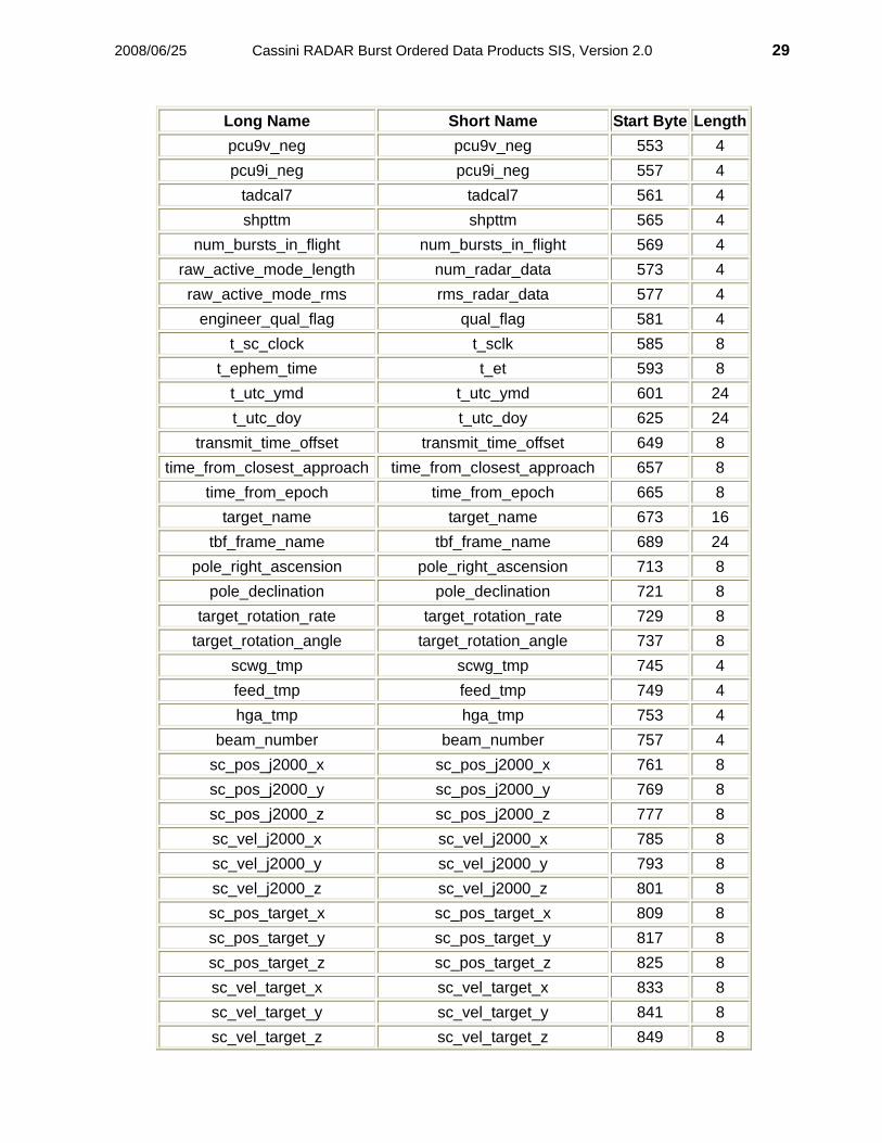
8.1 SBDR Start Byte Table The following table lists the starting byte of each field in a SBDR record along with long
and short names for each field and its length in bytes. The long names are the names used to document the field and the names employed in the PDS format file `SBDR.FMT' (See Appendix B). The short names are values occurring in the ground processing software and are included here to assist the software developers. An SBDR record is 1272 bytes long.
SBDR Start Byte Table
Long Name Short Name Start Byte Lengthsync sync 1 4
spacecraft_clock sclk 5 4 burst_id burst_id 9 4
cds_pickup_rate scpr 13 4 burst_start_time brst 17 4
header_tfi header_tfi 21 4 header_tnc header_tnc 25 4 header_typ header_typ 29 4 header_tca header_tca 33 4 header_tcb header_tcb 37 4 header_tcc header_tcc 41 4
pwri pwri 45 4 vicc vicc 49 4 vimc vimc 53 4
tail_len tail_len 57 4 tail_id tail_id 61 4
sab_counter sab_counter 65 4 sab_len sab_len 69 4
fswm fswm 73 4 fswc fswc 77 4 ctbc ctbc 81 4
rx_window_pri ctrx 85 4 ctps ctps 89 4 ctbe ctbe 93 4
ctps_ctbe ctps_ctbe 97 4 header_end header_end 101 4
slow_tfi slow_tfi 105 4

2008/06/25 Cassini RADAR Burst Ordered Data Products SIS, Version 2.0 26
Long Name Short Name Start Byte Lengthdata_take_number dtn 109 4
slow_typ slow_typ 113 4 calibration_source csr 117 4
radar_mode r_mode 121 4 sin sin 125 4
bem bem 129 4 baq_mode baq_mode 133 4
tro tro 137 4 receiver_bandwidth rc_bw 141 4
adc_rate adc 145 4 at1_tot at1_tot 149 4 at3_tot at3_tot 153 4 at4_tot at4_tot 157 4
at1_each at1_each 161 4 at3_each at3_each 165 4 at4_each at4_each 169 4
antenna_int_period rip 173 4 chirp_time_step csd 177 4 num_rad_meas rad 181 4
num_chirp_steps csq 185 4 chirp_length chirp_length 189 4
chirp_freq_step slow_cfs 193 4 fast_tfi fast_tfi 197 4
fin fin 201 4 fast_type fast_type 205 4
num_pulses pul 209 4 bii bii 213 4
burst_period bpd 217 4 pri pri 221 4
rx_window_delay rwd 225 4 chirp_start_freq fast_csf 229 4
iebtth iebtth 233 4 iebttl iebttl 237 4
bgcalls bgcalls 241 4 delvmn delvmn 245 4 delvda delvda 249 4 delvyr delvyr 253 4

2008/06/25 Cassini RADAR Burst Ordered Data Products SIS, Version 2.0 27
Long Name Short Name Start Byte Lengthraw_res_load_meas cnt_rl 257 4 raw_antenna_meas cnt_radio 261 4
raw_noise_diode_meas cnt_nd 265 4 eout eout 269 4 subr subr 273 4
space_craft_time space_craft_time 277 4 noise_diode_int_period hip 281 4
res_load_int_period cip 285 4 fwdtmp fwdtmp 289 4 be1tmp be1tmp 293 4 be2tmp be2tmp 297 4 be3tmp be3tmp 301 4 be4tmp be4tmp 305 4 be5tmp be5tmp 309 4 diptmp diptmp 313 4 rlotmp rlotmp 317 4 tadcal1 tadcal1 321 4 nsdtmp nsdtmp 325 4 lnatmp lnatmp 329 4 evdtmp evdtmp 333 4 mratmp mratmp 337 4 mruttm mruttm 341 4 dcgttm dcgttm 345 4 cucttm cucttm 349 4 twttmp twttmp 353 4 epctmp epctmp 357 4 tw1ttm tw1ttm 361 4 ep1ttm ep1ttm 365 4 p_stmp p_stmp 369 4 p_sttm p_sttm 373 4 fguttm fguttm 377 4 tadcal4 tadcal4 381 4 esstmp esstmp 385 4 wgb1t1 wgb1t1 389 4 wgb3t1 wgb3t1 393 4 wgb3t2 wgb3t2 397 4 wgb3t3 wgb3t3 401 4

2008/06/25 Cassini RADAR Burst Ordered Data Products SIS, Version 2.0 28
Long Name Short Name Start Byte Lengthwgb5t1 wgb5t1 405 4 pcutmp pcutmp 409 4 adctmp adctmp 413 4 tadcal2 tadcal2 417 4 ecltmp ecltmp 421 4 cputmp cputmp 425 4
memtmp memtmp 429 4 sadctmp sadctmp 433 4 tadcal3 tadcal3 437 4 frwdpw frwdpw 441 4 dcgmon dcgmon 445 4
lpltlm lpltlm 449 4 nsdcur nsdcur 453 4 hpapsm hpapsm 457 4 catcur catcur 461 4
p_smon p_smon 465 4 svlsta svlsta 469 4
usotmp usotmp 473 4 cpbnkv cpbnkv 477 4 essvlt essvlt 481 4
tadcal5 tadcal5 485 4 pcu5v_pos pcu5v_pos 489 4 pcu5i_pos pcu5i_pos 493 4 pcu5v_neg pcu5v_neg 497 4 pcu5i_neg pcu5i_neg 501 4
pcu15v_pos pcu15v_pos 505 4 pcu15i_pos pcu15i_pos 509 4 pcu15v_neg pcu15v_neg 513 4 pcu15i_neg pcu15i_neg 517 4 pcu12v_neg pcu12v_neg 521 4 pcu12i_neg pcu12i_neg 525 4
pcucur pcucur 529 4 pllmon pllmon 533 4 ctu5i ctu5i 537 4
tadcal6 tadcal6 541 4 pcu9v_pos pcu9v_pos 545 4 pcu9i_pos pcu9i_pos 549 4
2008/06/25 Cassini RADAR Burst Ordered Data Products SIS, Version 2.0 29
Long Name Short Name Start Byte Lengthpcu9v_neg pcu9v_neg 553 4 pcu9i_neg pcu9i_neg 557 4
tadcal7 tadcal7 561 4 shpttm shpttm 565 4
num_bursts_in_flight num_bursts_in_flight 569 4 raw_active_mode_length num_radar_data 573 4 raw_active_mode_rms rms_radar_data 577 4
engineer_qual_flag qual_flag 581 4 t_sc_clock t_sclk 585 8
t_ephem_time t_et 593 8 t_utc_ymd t_utc_ymd 601 24 t_utc_doy t_utc_doy 625 24
transmit_time_offset transmit_time_offset 649 8 time_from_closest_approach time_from_closest_approach 657 8
time_from_epoch time_from_epoch 665 8 target_name target_name 673 16
tbf_frame_name tbf_frame_name 689 24 pole_right_ascension pole_right_ascension 713 8
pole_declination pole_declination 721 8 target_rotation_rate target_rotation_rate 729 8
target_rotation_angle target_rotation_angle 737 8 scwg_tmp scwg_tmp 745 4 feed_tmp feed_tmp 749 4 hga_tmp hga_tmp 753 4
beam_number beam_number 757 4 sc_pos_j2000_x sc_pos_j2000_x 761 8 sc_pos_j2000_y sc_pos_j2000_y 769 8 sc_pos_j2000_z sc_pos_j2000_z 777 8 sc_vel_j2000_x sc_vel_j2000_x 785 8 sc_vel_j2000_y sc_vel_j2000_y 793 8 sc_vel_j2000_z sc_vel_j2000_z 801 8 sc_pos_target_x sc_pos_target_x 809 8 sc_pos_target_y sc_pos_target_y 817 8 sc_pos_target_z sc_pos_target_z 825 8 sc_vel_target_x sc_vel_target_x 833 8 sc_vel_target_y sc_vel_target_y 841 8 sc_vel_target_z sc_vel_target_z 849 8

2008/06/25 Cassini RADAR Burst Ordered Data Products SIS, Version 2.0 30
Long Name Short Name Start Byte Lengthsc_x_axis_j2000_x sc_x_axis_j2000_x 857 8 sc_x_axis_j2000_y sc_x_axis_j2000_y 865 8 sc_x_axis_j2000_z sc_x_axis_j2000_z 873 8 sc_y_axis_j2000_x sc_y_axis_j2000_x 881 8 sc_y_axis_j2000_y sc_y_axis_j2000_y 889 8 sc_y_axis_j2000_z sc_y_axis_j2000_z 897 8 sc_z_axis_j2000_x sc_z_axis_j2000_x 905 8 sc_z_axis_j2000_y sc_z_axis_j2000_y 913 8 sc_z_axis_j2000_z sc_z_axis_j2000_z 921 8 sc_x_axis_target_x sc_x_axis_target_x 929 8 sc_x_axis_target_y sc_x_axis_target_y 937 8 sc_x_axis_target_z sc_x_axis_target_z 945 8 sc_y_axis_target_x sc_y_axis_target_x 953 8 sc_y_axis_target_y sc_y_axis_target_y 961 8 sc_y_axis_target_z sc_y_axis_target_z 969 8 sc_z_axis_target_x sc_z_axis_target_x 977 8 sc_z_axis_target_y sc_z_axis_target_y 985 8 sc_z_axis_target_z sc_z_axis_target_z 993 8
rot_vel_j2000_x rot_vel_j2000_x 1001 8 rot_vel_j2000_y rot_vel_j2000_y 1009 8 rot_vel_j2000_z rot_vel_j2000_z 1017 8 rot_vel_target_x rot_vel_target_x 1025 8 rot_vel_target_y rot_vel_target_y 1033 8 rot_vel_target_z rot_vel_target_z 1041 8
norm_cnt_rl norm_cnt_rl 1049 4 norm_cnt_nd norm_cnt_nd 1053 4
norm_cnt_radio norm_cnt_radio 1057 4 science_qual_flag science_qual_flag 1061 4
system_gain system_gain 1065 4 antenna_temp antenna_temp 1069 4 receiver_temp receiver_temp 1073 4 ant_temp_std ant_temp_std 1077 4
pass_geom_time_offset pass_geom_time_offset 1081 4 pass_pol_angle pass_pol_angle 1085 4
pass_emission_angle pass_emission_angle 1089 4 pass_azimuth_angle pass_azimuth_angle 1093 4 pass_centroid_lon pass_centroid_lon 1097 4

2008/06/25 Cassini RADAR Burst Ordered Data Products SIS, Version 2.0 31
Long Name Short Name Start Byte Lengthpass_centroid_lat pass_centroid_lat 1101 4 pass_major_width pass_major_width 1105 4 pass_minor_width pass_minor_width 1109 4
pass_ellipse_pt1_lon pass_ellipse_pt1_lon 1113 4 pass_ellipse_pt2_lon pass_ellipse_pt2_lon 1117 4 pass_ellipse_pt3_lon pass_ellipse_pt3_lon 1121 4 pass_ellipse_pt4_lon pass_ellipse_pt4_lon 1125 4 pass_ellipse_pt1_lat pass_ellipse_pt1_lat 1129 4 pass_ellipse_pt2_lat pass_ellipse_pt2_lat 1133 4 pass_ellipse_pt3_lat pass_ellipse_pt3_lat 1137 4 pass_ellipse_pt4_lat pass_ellipse_pt4_lat 1141 4
num_pulses_received num_pulses_received 1145 4 total_echo_energy total_echo_energy 1149 4 noise_echo_energy noise_echo_energy 1153 4
x_factor x_factor 1157 4 sigma0_uncorrected sigma0 1161 4
sigma0_corrected sigma0_corrected 1165 4 sigma0_uncorrected_std sigma0_uncorrected_std 1169 4
surface_height surface_height 1173 4 surf_ht_std surf_ht_std 1177 4
act_geom_time_offset act_geom_time_offset 1181 4 act_pol_angle act_pol_angle 1185 4
act_incidence_angle act_incidence_angle 1189 4 act_azimuth_angle act_azimuth_angle 1193 4 act_centroid_lon act_centroid_lon 1197 4 act_centroid_lat act_centroid_lat 1201 4 act_major_width act_major_width 1205 4 act_minor_width act_minor_width 1209 4
act_ellipse_pt1_lon act_ellipse_pt1_lon 1213 4 act_ellipse_pt2_lon act_ellipse_pt2_lon 1217 4 act_ellipse_pt3_lon act_ellipse_pt3_lon 1221 4 act_ellipse_pt4_lon act_ellipse_pt4_lon 1225 4 act_ellipse_pt1_lat act_ellipse_pt1_lat 1229 4 act_ellipse_pt2_lat act_ellipse_pt2_lat 1233 4 act_ellipse_pt3_lat act_ellipse_pt3_lat 1237 4 act_ellipse_pt4_lat act_ellipse_pt4_lat 1241 4
altimeter_profile_range_start altimeter_profile_range_start 1245 4

2008/06/25 Cassini RADAR Burst Ordered Data Products SIS, Version 2.0 32
Long Name Short Name Start Byte Lengthaltimeter_profile_range_step altimeter_profile_range_step 1249 4
altimeter_profile_length altimeter_profile_length 1253 4 sar_azimuth_res sar_azimuth_res 1257 4 sar_range_res sar_range_res 1261 4
sar_centroid_bidr_lon sar_centroid_bidr_lon 1265 4 sar_centroid_bidr_lat sar_centroid_bidr_lat 1269 4
8.2 List of SBDR Field Descriptions Data items below are numbered 8.2.n.#, where n = 1, 2, 3 for Engineering, Intermediate,
Science Data Segments in order to keep a running count of the items.
8.2.1 Engineering Data Segment Fields
8.2.n.1 sync Constant hexadecimal value used for binary format checking. PDS_Object: Column of Table conceptual_type: real storage_type: unint32 number_of_bytes: 4 units: none minimum_value: 77746B6A hexadecimal maximum_value: 77746B6A hexadecimal
8.2.n.2 spacecraft_clock (sclk) Reference spacecraft clock count for each burst. The LSB is nearly 1 second but not
exactly. For exact time references use t_ephem_time PDS_Object: Column of Table conceptual_type: real storage_type: unint32 number_of_bytes: 4 units: 1 spacecraft clock count minimum_value: 0 maximum_value: 232 -1
8.2.n.3 burst_id An identifier for each burst which is unique for the course of the mission. Consecutive bursts within a data take have consecutive record_id values. PDS_Object: Column of Table conceptual_type: real storage_type: unint32 number_of_bytes: 4

2008/06/25 Cassini RADAR Burst Ordered Data Products SIS, Version 2.0 33
units: none minimum_value: 0 maximum_value: 232 -1
8.2.n.4 cds_pickup_rate (scpr) CDS pickup rate. PDS_Object: Column of Table conceptual_type: real storage_type: unint32 number_of_bytes: 4 units: bits/s valid_values: 364800, or 30400
8.2.n.5 burst_start_time (brst) Burst start time expressed as an offset from the reference spacecraft clock count. The precise spacecraft time at the start of the burst is sclk + brst in seconds. PDS_Object: Column of Table conceptual_type: real storage_type: unint32 number_of_bytes: 4 units: s minimum_value: 0.0 maximum_value: 1.0
8.2.n.6 header_tfi Specified execute time of test and control instruction expressed as time after IEB trigger,
bits 0-15 of Test and Control IEB instruction. PDS_Object: Column of Table
conceptual_type: real storage_type: float32 number_of_bytes: 4 units: s minimum_value: 0 maximum_value: 65535 (18.2 hours)
8.2.n.7 header_tnc Test and control mode, bits 24-31 of Test and Control IEB. PDS_Object: Column of Table conceptual_type: real storage_type: unint32 number_of_bytes: 4 units: none minimum_value: 0 maximum_value: 255

2008/06/25 Cassini RADAR Burst Ordered Data Products SIS, Version 2.0 34
8.2.n.8 header_typ Instruction type (test and control), bits 22-23 of Test and Control IEB. PDS_Object: Column of Table conceptual_type: real storage_type: unint32 number_of_bytes: 4 units: none possible value: 1
8.2.n.9 header_tca Test and Control Parameter A, bits32-47 of Test and Control IEB PDS_Object: Column of Table conceptual_type: real storage_type: unint32 number_of_bytes: 4 units: none minimum_value: 0 maximum_value: 65535
8.2.n.10 header_tcb Test and Control Parameter B, bits 48-63 of Test and Control IEB PDS_Object: Column of Table conceptual_type: real storage_type: unint32 number_of_bytes: 4 units: none minimum_value: 0 maximum_value: 65535
8.2.n.11 header_tcc Test and Control Parameter C, bits 64-79 of Test and Control IEB PDS_Object: Column of Table conceptual_type: real storage_type: unint32 number_of_bytes: 4 units: none minimum_value: 0 maximum_value: 65535
8.2.n.12 pwri Most recent power instruction. PDS_Object: Column of Table conceptual_type: real storage_type: unint32

2008/06/25 Cassini RADAR Burst Ordered Data Products SIS, Version 2.0 35
number_of_bytes: 4 units: none minimum_value: 0 maximum_value: 232 -1
8.2.n.13 vicc Valid/invalid spacecraft command count (least significant 16 bits). Bit 0 (MSB) 0=valid,
1=invalid. Bits 1-15 represent command counter. PDS_Object: Column of Table conceptual_type: real storage_type: unint32 number_of_bytes: 4 units: none minimum_value: 0 maximum_value: 65535
8.2.n.14 vimc Valid/invalid spacecraft message count (least significant 16 bits). Bit 0 (MSB) 0=valid,
1=invalid. Bits 1-15 represent message counter. PDS_Object: Column of Table conceptual_type: real storage_type: unint32 number_of_bytes: 4 units: none minimum_value: 0 maximum_value: 65535
8.2.n.15 tail_len Word (16-bit) count of SAR/ Altimeter Block (SAB) tail. PDS_Object: Column of Table conceptual_type: real storage_type: unint32 number_of_bytes: 4 units: none possible values: 0 (no tail), 32, 16384
8.2.n.16 tail_id Running count of non-zero length SAB tails. PDS_Object: Column of Table conceptual_type: real storage_type: unint32 number_of_bytes: 4 units: none minimum_value: 0

2008/06/25 Cassini RADAR Burst Ordered Data Products SIS, Version 2.0 36
maximum_value: 65535
8.2.n.17 sab_counter Running count of SABs. PDS_Object: Column of Table conceptual_type: real storage_type: unint32 number_of_bytes: 4 units: none minimum_value: 0 maximum_value: 65535
8.2.n.18 sab_len Word (16-bit) count of SAB data field. PDS_Object: Column of Table conceptual_type: real storage_type: unint32 number_of_bytes: 4 units: none minimum_value: 0 maximum_value: 65535
8.2.n.19 fswm Flight software error module ID. PDS_Object: Column of Table conceptual_type: real storage_type: unint32 number_of_bytes: 4 units: none minimum_value: 0 maximum_value: 255
8.2.n.20 fswc Flight software error code. PDS_Object: Column of Table conceptual_type: real storage_type: unint32 number_of_bytes: 4 units: none minimum_value: 0 maximum_value: 255
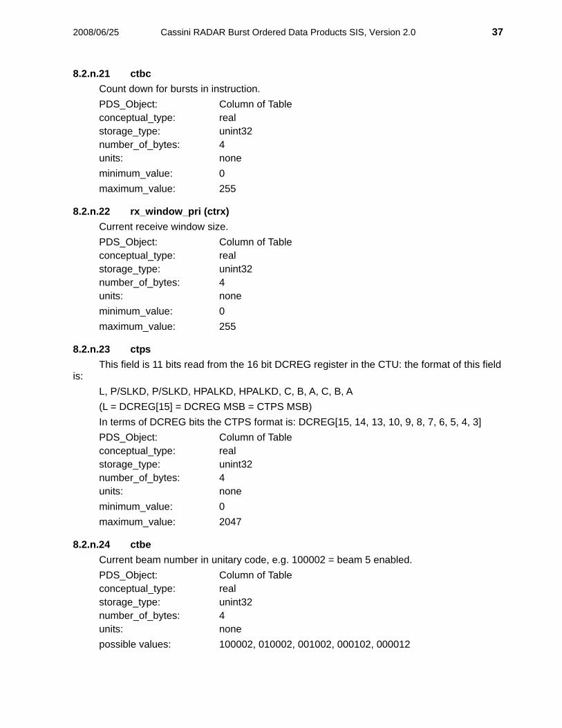
2008/06/25 Cassini RADAR Burst Ordered Data Products SIS, Version 2.0 37
8.2.n.21 ctbc Count down for bursts in instruction. PDS_Object: Column of Table conceptual_type: real storage_type: unint32 number_of_bytes: 4 units: none minimum_value: 0 maximum_value: 255
8.2.n.22 rx_window_pri (ctrx) Current receive window size. PDS_Object: Column of Table conceptual_type: real storage_type: unint32 number_of_bytes: 4 units: none minimum_value: 0 maximum_value: 255
8.2.n.23 ctps This field is 11 bits read from the 16 bit DCREG register in the CTU: the format of this field
is: L, P/SLKD, P/SLKD, HPALKD, HPALKD, C, B, A, C, B, A (L = DCREG[15] = DCREG MSB = CTPS MSB) In terms of DCREG bits the CTPS format is: DCREG[15, 14, 13, 10, 9, 8, 7, 6, 5, 4, 3] PDS_Object: Column of Table conceptual_type: real storage_type: unint32 number_of_bytes: 4 units: none minimum_value: 0 maximum_value: 2047
8.2.n.24 ctbe Current beam number in unitary code, e.g. 100002 = beam 5 enabled. PDS_Object: Column of Table conceptual_type: real storage_type: unint32 number_of_bytes: 4 units: none possible values: 100002, 010002, 001002, 000102, 000012

2008/06/25 Cassini RADAR Burst Ordered Data Products SIS, Version 2.0 38
8.2.n.25 ctps_ctbe Original telemetry 16 bit encoding of CTPS (Most significant 11 bits) and CTBE (least
significant 5 bits) stored as a 32 bit integer. PDS_Object: Column of Table conceptual_type: real storage_type: unint32 number_of_bytes: 4 units: none minimum_value: 0 maximum_value: 64094
8.2.n.26 header_end Instruction read back disagree (IRBD) which consists of 17 single bit flags at the end of a
SAB header. PDS_Object: Column of Table conceptual_type: real storage_type: unint32 number_of_bytes: 4 units: none minimum_value: 0 maximum_value: 255 maximum_value: 217 - 1
8.2.n.27 slow_tfi Time from IEB trigger for slow field instruction. PDS_Object: Column of Table conceptual_type: real storage_type: unint32 number_of_bytes: 4 units: none minimum_value: 0 maximum_value: 65535 (18.2 hours)
8.2.n.28 data_take_number (dtn) Data take number. Definition: 000000002 = the first IEB Sequence Table uploaded after launch. The MOS will increment this parameter by one for every new IEB Sequence Table that is
uploaded. This value will "roll over" from 255 to 0 if necessary. Typical events that will cause the generation and uploading of a new IEB Sequence Table
include: • Normal Radar SAR or ALT operation at Titan • Calibration not associated with normal operation (e.g. period Cruise Phase calibration) • Icy satellite measurements, imaging • "Target-of-opportunity" measurements, imaging

2008/06/25 Cassini RADAR Burst Ordered Data Products SIS, Version 2.0 39
PDS_Object: Column of Table conceptual_type: real storage_type: unint32 number_of_bytes: 4 units: none minimum_value: 0 maximum_value: 255
8.2.n.29 slow_typ Slow field instruction type (3). PDS_Object: Column of Table conceptual_type: real storage_type: unint32 number_of_bytes: 4 units: none minimum_value: 0 possible value: 3
8.2.n.30 calibration_source (csr) Calibration source. The following bit patterns are assigned to the various Calibration Sources: (the three or
four character mode name is in parenthesis) 00002 = Normal Operation. (norm) 00012 = Antenna being used as the Calibration Source. (ant) 00102 = Noise Diode being used as the Calibration Source. (diod) 00112 = Resistive Load being used as the Calibration Source. (load) 01002 = Rerouted Chirp being used as the Calibration Source. (chrp) 01012 = Leakage Signal being used as the Calibration Source. (leak) 01102 = Radiometer Only Calibration Mode. (rado) 01112 = Transmit Only Calibration Mode. (xmto) 10002 = Auto-Gain Control. (agc) 10012 - 11112 = (reserved by the CTU) PDS_Object: Column of Table conceptual_type: real storage_type: unint32 number_of_bytes: 4 units: none minimum_value: 0 maximum_value: 15

2008/06/25 Cassini RADAR Burst Ordered Data Products SIS, Version 2.0 40
8.2.n.31 radar_mode (r_mode) This field represents the radar mode, and is defined as follows:
(the four character mode name is in parenthesis) 00002 = ALTL: Altimeter, Low-Resolution (altl) 00012 = ALTH: Altimeter, High-Resolution (alth) 00102 = SARL: Synthetic Aperture Radar, Low-Resolution (sarl) 00112 = SARH: Synthetic Aperture Radar, High-Resolution (sarh) 01002 = Radiometer Only (rado) 01012 = Inter-Galactic Object (IGO) Calibration (igoc) 01102 = Earth Viewing Calibration (evca) 01112 = Bi-Static Operation (bsop) 10002 = ALTL with Auto Gain (alag) 10012 = ALTH with Auto Gain (ahag) 10102 = SARL with Auto Gain (slag) 10112 = SARH with Auto Gain (shag) 11002-11112 = (spare) PDS_Object: Column of Table conceptual_type: real storage_type: unint32 number_of_bytes: 4 units: none minimum_value: 0 maximum_value: 15
8.2.n.32 sin Slow field instruction number. The MOS will reset this parameter to zero (000000002) for
every Data Take, and will increment this parameter by one for every slow field instruction. This value will "roll over" from 255 to 0 if necessary.
PDS_Object: Column of Table conceptual_type: real storage_type: unint32 number_of_bytes: 4 units: none minimum_value: 0 maximum_value: 255
8.2.n.33 bem Beam mask. The following bit patterns describe the possible Beam Masks used by the Cassini RADAR
DSS: 000002 = All beams disabled (Used during internal source Calibration modes such as
noise diode, resistive load and rerouted chirp).

2008/06/25 Cassini RADAR Burst Ordered Data Products SIS, Version 2.0 41
000012 = Beam #1 Only enabled. 000102 = Beam #2 Only enabled. 000112 = Beams #2 and #1 enabled. 100002 = Beam #5 Only enabled. 110102 = Beams #5, #4 and #2 enabled. 111112 = All Five Beams enabled. PDS_Object: Column of Table conceptual_type: real storage_type: unint32 number_of_bytes: 4 units: none minimum_value: 0 maximum_value: 31
8.2.n.34 baq_mode BAQ compression mode. The following bit patterns are assigned to the various BAQ Modes: 0002 = 8-to-2 bit Block Adaptive Quantization (normally used SAR mode) 0012 = 8-to-1 bit Block Adaptive Quantization (i.e. sign bit and thresholds, only) 0102 = 8 bit to 0 (no active mode data) 0112 = 8 bit to 2 MSB's 1002 = 8 bit to 4 MSB's 1012 = 8 bits straight (normally used Calibration mode) 1102 = 8-to-4 bit Block Adaptive Quantization (normally used Low Res ALT mode) 1112 = 8-to-4 bit Block Adaptive Quantization (normally used Hi Res ALT mode) PDS_Object: Column of Table conceptual_type: real storage_type: unint32 number_of_bytes: 4 units: none minimum_value: 0 maximum_value: 7
8.2.n.35 tro Transmit Burst/Receive Window Offset. The Transmit Burst/Receive Window Offset is the difference between the length of the
Transmit Burst and the length of the Receive Window. PDS_Object: Column of Table conceptual_type: real storage_type: float32
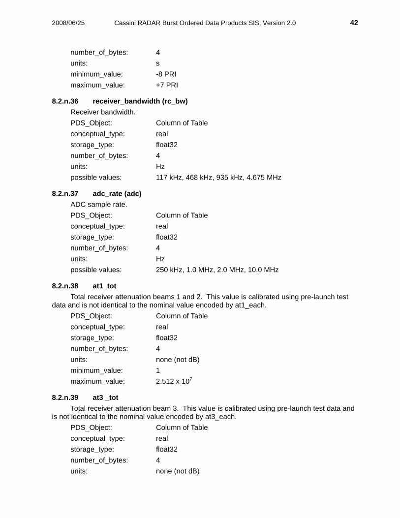
2008/06/25 Cassini RADAR Burst Ordered Data Products SIS, Version 2.0 42
number_of_bytes: 4 units: s minimum_value: -8 PRI maximum_value: +7 PRI
8.2.n.36 receiver_bandwidth (rc_bw) Receiver bandwidth. PDS_Object: Column of Table conceptual_type: real storage_type: float32 number_of_bytes: 4 units: Hz possible values: 117 kHz, 468 kHz, 935 kHz, 4.675 MHz
8.2.n.37 adc_rate (adc) ADC sample rate. PDS_Object: Column of Table conceptual_type: real storage_type: float32 number_of_bytes: 4 units: Hz possible values: 250 kHz, 1.0 MHz, 2.0 MHz, 10.0 MHz
8.2.n.38 at1_tot Total receiver attenuation beams 1 and 2. This value is calibrated using pre-launch test
data and is not identical to the nominal value encoded by at1_each. PDS_Object: Column of Table conceptual_type: real storage_type: float32 number_of_bytes: 4 units: none (not dB) minimum_value: 1 maximum_value: 2.512 x 10⁷
8.2.n.39 at3 _tot Total receiver attenuation beam 3. This value is calibrated using pre-launch test data and
is not identical to the nominal value encoded by at3_each. PDS_Object: Column of Table conceptual_type: real storage_type: float32 number_of_bytes: 4 units: none (not dB)

2008/06/25 Cassini RADAR Burst Ordered Data Products SIS, Version 2.0 43
minimum_value: 1 maximum_value: 2.512 x 10⁷
8.2.n.40 at4 _tot Total receiver attenuation beam 4 and 5. This value is calibrated using pre-launch test
data and is not identical to the nominal value encoded by at4_each. PDS_Object: Column of Table conceptual_type: real storage_type: float32 number_of_bytes: 4 units: none (not dB) minimum_value: 1 maximum_value: 2.512 x 10⁷
8.2.n.41 at1_each This parameter describes the attenuation for the Microwave Receiver (MR) in the RFES
when either Antenna Beam #1 or #2 are selected. The least significant twelve bits actually report three separate attenuators in the RFES MR.
From MSB to LSB: Bits [11,...,07] report the commanded attenuation (0dB - 31dB) of attenuator #1 (resolution
of 1 dB). Bits [06,...,02] report the commanded attenuation (0dB - 31dB) of attenuator #2 (resolution of 1 dB). Bits [01,00] report the commanded attenuation (0dB - 12dB) of attenuator #3 (resolution of 4 dB). The total nominal attenuation is the sum of the three attenuator settings (in dB).
PDS_Object: Column of Table conceptual_type: real storage_type: unint32 number_of_bytes: 4 units: none minimum_value: 0 maximum_value: 4095
8.2.n.42 at3_each This parameter describes the attenuation for the Microwave Receiver (MR) in the RFES
when Antenna Beam #3 is selected. The least significant twelve bits actually report three separate attenuators in the RFES MR.
From MSB to LSB: Bits [11,...,07] report the commanded attenuation (0dB - 31dB) of attenuator #1 (resolution
of 1 dB). Bits [06,...,02] report the commanded attenuation (0dB - 31dB) of attenuator #2 (resolution of 1 dB). Bits [01,00] report the commanded attenuation (0dB - 12dB) of attenuator #3 (resolution of 4 dB). The total nominal attenuation is the sum of the three attenuator settings (in dB).
PDS_Object: Column of Table conceptual_type: real storage_type: unint32

2008/06/25 Cassini RADAR Burst Ordered Data Products SIS, Version 2.0 44
number_of_bytes: 4 units: none minimum_value: 0 maximum_value: 4095
8.2.n.43 at4_each This parameter describes the attenuation for the Microwave Receiver (MR) in the RFES
when either Antenna Beam #4 or #5 are selected. The least significant twelve bits actually report three separate attenuators in the RFES MR.
From MSB to LSB: Bits [11,...,07] report the commanded attenuation (0dB - 31dB) of attenuator #1 (resolution
of 1 dB). Bits [06,...,02] report the commanded attenuation (0dB - 31dB) of attenuator #2 (resolution of 1 dB). Bits [01,00] report the commanded attenuation (0dB - 12dB) of attenuator #3 (resolution of 4 dB). The total nominal attenuation is the sum of the three attenuator settings (in dB).
PDS_Object: Column of Table conceptual_type: real storage_type: unint32 number_of_bytes: 4 units: none minimum_value: 0 maximum_value: 4095
8.2.n.44 antenna_int_period (rip) Radiometer integration period. This parameter is the length of time during which passive
signal energy received by the antenna is measured during each radiometer measurement. PDS_Object: Column of Table conceptual_type: real storage_type: float32 number_of_bytes: 4 units: s minimum_value: 0.010 s maximum_value: 0.075 s
8.2.n.45 chirp_time_step (csd) Chirp step duration, the duration in time of each single frequency step. PDS_Object: Column of Table conceptual_type: real storage_type: float32 number_of_bytes: 4 units: s possible_values: should always be 666.7 ns

2008/06/25 Cassini RADAR Burst Ordered Data Products SIS, Version 2.0 45
8.2.n.46 num_rad_meas (rad) Radiometer window counts. The number of times within a "burst" that radiometer
measurements occur. PDS_Object: Column of Table conceptual_type: real storage_type: unint32 number_of_bytes: 4 units: none minimum_value: 1 maximum_value: 255
8.2.n.47 num_chirp_steps (csq) Chirp step quantity, number of frequency changes used to perform a chirp. (For example, a chirp estimated by two discrete frequencies exhibits one frequency
change, hence csq=1.) PDS_Object: Column of Table conceptual_type: real storage_type: unint32 number_of_bytes: 4 units: none minimum_value: 216 maximum_value: 749
8.2.n.48 chirp_length Total length of a chirped signal in time, i.e. csd(csq+1). PDS_Object: Column of Table conceptual_type: real storage_type: float32 number_of_bytes: 4 units: s minimum_value: 0.144 ms maximum_value: 0.5 ms
8.2.n.49 chirp_freq_step (slow_cfs) Chirp frequency step size. PDS_Object: Column of Table conceptual_type: real storage_type: float32 number_of_bytes: 4 units: Hz minimum_value: 0 Hz maximum_value: 117.2 kHz

2008/06/25 Cassini RADAR Burst Ordered Data Products SIS, Version 2.0 46
8.2.n.50 fast_tfi Time from IEB trigger for fast field instruction. PDS_Object: Column of Table conceptual_type: real storage_type: float32 number_of_bytes: 4 units: s minimum_value: 0 maximum_value: 65535 (18.2 hours)
8.2.n.51 fin Fast field instruction number. The MOS will reset this parameter to zero (000000002) for
every Data Take, and will increment this parameter by one for every fast field Instruction. This value will "roll over" from 255 to 0 if necessary.
PDS_Object: Column of Table conceptual_type: real storage_type: unint32 number_of_bytes: 4 units: none minimum_value: 0 maximum_value: 255
8.2.n.52 fast_typ Instruction type (fast field=2) PDS_Object: Column of Table conceptual_type: real storage_type: unint32 number_of_bytes: 4 units: none possible_value: 2
8.2.n.53 num_pulses (pul) Number of pulses per burst. PDS_Object: Column of Table conceptual_type: real storage_type: unint32 number_of_bytes: 4 units: none minimum_value: 0 maximum_value: 255
8.2.n.54 bii Bursts in instruction. Bursts in Instruction represents to total number of Bursts (i.e., Burst Periods) to be
generated per Fast Field Instruction.

2008/06/25 Cassini RADAR Burst Ordered Data Products SIS, Version 2.0 47
Hardware in the DSS maintains a count of the number of Bursts generated for each Fast Field Instruction, and when the appropriate number of complete Burst Periods has elapsed, that hardware generate an interrupt to the Flight Computer, and stops generating Bursts.
If Bursts in Instruction is zero, the DSS is in the so-called "Perpetual Instruction" mode. In this mode, the Digital Subsystem generates waveforms based on a given Fast/Slow instruction pair for an indefinite amount of time (i.e., it will not be limited by the upper range of the bii parameter).
PDS_Object: Column of Table conceptual_type: real storage_type: unint32 number_of_bytes: 4 units: none minimum_value: 0 maximum_value: 255
8.2.n.55 burst_period (bpd) Burst period. The Burst Period is the total time interval allocated for the transmission of
pulses, the receipt of echoes, and the taking of Radiometry data. PDS_Object: Column of Table conceptual_type: real storage_type: float32 number_of_bytes: 4 units: s minimum_value: 10 ms maximum_value: 4.095 s
8.2.n.56 pri Pulse repetition interval. This parameter is the time interval between successive
transmitted (chirped) pulses. PDS_Object: Column of Table conceptual_type: real storage_type: float32 number_of_bytes: 4 units: s minimum_value: 0.002 ms maximum_value: 4.092 ms
8.2.n.57 rx_window_delay (rwd) The Receive Window Delay (as defined in the DSS) is measured from the beginning of the
first pulse in the first PRI that makes up the Transmit Burst. It includes the PRIs that make up the Transmit Burst and the PRIs between the end of Transmit Burst and the beginning of the Receive Window. The Receive Window Delay will always be an integer number of PRIs.
PDS_Object: Column of Table conceptual_type: real storage_type: float32 number_of_bytes: 4

2008/06/25 Cassini RADAR Burst Ordered Data Products SIS, Version 2.0 48
units: s minimum_value: 0 maximum_value: 1023 PRI
8.2.n.58 chirp_start_freq (fast_csf) Chirp start frequency is defined as the frequency of the first frequency step that forms the
chirp. PDS_Object: Column of Table conceptual_type: real storage_type: float32 number_of_bytes: 4 units: Hz minimum_value: 0 Hz maximum_value: 30 MHz
8.2.n.59 iebtth Most significant 16 bits of the IEB trigger time or the ILX execution time. PDS_Object: Column of Table conceptual_type: real storage_type: unint32 number_of_bytes: 4 units: none minimum_value: 0 maximum_value: 65535
8.2.n.60 iebttl Least significant 16 bits of the IEB trigger time or the ILX execution time. PDS_Object: Column of Table conceptual_type: real storage_type: unint32 number_of_bytes: 4 units: none minimum_value: 0 maximum_value: 65535
8.2.n.61 bgcalls Number of calls to the background task during one ETA interrupt period. (Flight S/W only) PDS_Object: Column of Table conceptual_type: real storage_type: unint32 number_of_bytes: 4 units: none minimum_value: 0 maximum_value: 65535

2008/06/25 Cassini RADAR Burst Ordered Data Products SIS, Version 2.0 49
8.2.n.62 delvmn BSL or CROC-FSW delivery date: month. PDS_Object: Column of Table conceptual_type: real storage_type: unint32 number_of_bytes: 4 units: month minimum_value: 1 maximum_value: 12
8.2.n.63 delvda BSL or CROC-FSW delivery date: day. PDS_Object: Column of Table conceptual_type: real storage_type: unint32 number_of_bytes: 4 units: day of month minimum_value: 1 maximum_value: 31
8.2.n.64 delvyr BSL or CROC-FSW delivery date: year PDS_Object: Column of Table conceptual_type: real storage_type: unint32 number_of_bytes: 4 units: year minimum_value: 1990 maximum_value: 2010
8.2.n.65 raw_res_load_meas (cnt_rl) Raw counts for resistive load measurement. PDS_Object: Column of Table conceptual_type: real storage_type: unint32 number_of_bytes: 4 units: none minimum_value: 0 maximum_value: 4095
8.2.n.66 raw_antenna_meas (cnt_radio) Raw counts for antenna (radiometer) measurement summed over all measurement
windows. PDS_Object: Column of Table conceptual_type: real

2008/06/25 Cassini RADAR Burst Ordered Data Products SIS, Version 2.0 50
storage_type: unint32 number_of_bytes: 4 units: none minimum_value: 0 maximum_value: 220 -1
8.2.n.67 raw_noise_diode_meas (cnt_nd) Raw counts for noise diode measurement. PDS_Object: Column of Table conceptual_type: real storage_type: unint32 number_of_bytes: 4 units: none minimum_value: 0 maximum_value: 4095
8.2.n.68 eout 3 LSBs of Engineering Flight Computer Output Discretes. These discrete bits are: OUT*2,
OUT*1 and OUT*0; they correspond to SWD*, TIS* and RMC* in the SDB. See Cassini RADAR DSS High Level Design document Section 4.6.1 for more information.
PDS_Object: Column of Table conceptual_type: real storage_type: unint32 number_of_bytes: 4 units: none minimum_value: 0 maximum_value: 7
8.2.n.69 subr SubCom row number for this burst. Indicates which elements of engineering telemetry
were most recently updated. See Cassini RADAR DSS High Level Design document Section 7.3 for more information.
PDS_Object: Column of Table conceptual_type: real storage_type: unint32 number_of_bytes: 4 units: none minimum_value: 0 maximum_value: 15
8.2.n.70 space_craft_time Twelve Least significant bits of spacecraft clock logged when the Engineering data in this
SubCom data set was acquired. PDS_Object: Column of Table conceptual_type: real storage_type: unint32

2008/06/25 Cassini RADAR Burst Ordered Data Products SIS, Version 2.0 51
number_of_bytes: 4 units: none minimum_value: 0 maximum_value: 4095
8.2.n.71 noise_diode_int_period (hip) Integration time of noise diode measurement. PDS_Object: Column of Table conceptual_type: real storage_type: float32 number_of_bytes: 4 units: s minimum_value: 0.0 maximum_value: 0.02
8.2.n.72 res_load_int_period (cip) Integration time of resistive load measurement. PDS_Object: Column of Table conceptual_type: real storage_type: float32 number_of_bytes: 4 units: s minimum_value: 0.0 maximum_value: 0.08
8.2.n.73 fwdtmp Forward diode temperature. PDS_Object: Column of Table conceptual_type: real storage_type: float32 number_of_bytes: 4 units: K
8.2.n.74 be1tmp Beam 1 temperature. PDS_Object: Column of Table conceptual_type: real storage_type: float32 number_of_bytes: 4 units: K
8.2.n.75 be2tmp Beam 2 temperature. PDS_Object: Column of Table conceptual_type: real

2008/06/25 Cassini RADAR Burst Ordered Data Products SIS, Version 2.0 52
storage_type: float32 number_of_bytes: 4 units: K
8.2.n.76 be3tmp Beam 3 temperature. PDS_Object: Column of Table conceptual_type: real storage_type: float32 number_of_bytes: 4 units: K
8.2.n.77 be4tmp Beam 4 temperature. PDS_Object: Column of Table conceptual_type: real storage_type: float32 number_of_bytes: 4 units: K
8.2.n.78 be5tmp Beam 5 temperature. PDS_Object: Column of Table conceptual_type: real storage_type: float32 number_of_bytes: 4 units: K
8.2.n.79 diptmp Diplexer temperature. PDS_Object: Column of Table conceptual_type: real storage_type: float32 number_of_bytes: 4 units: K
8.2.n.80 rlotmp Resistive load temperature. PDS_Object: Column of Table conceptual_type: real storage_type: float32 number_of_bytes: 4 units: K

2008/06/25 Cassini RADAR Burst Ordered Data Products SIS, Version 2.0 53
8.2.n.81 tadcal1 Thermistor calibration temperature. PDS_Object: Column of Table conceptual_type: real storage_type: float32 number_of_bytes: 4 units: K
8.2.n.82 nsdtmp Noise diode temperature. PDS_Object: Column of Table conceptual_type: real storage_type: float32 number_of_bytes: 4 units: K
8.2.n.83 lnatmp Low noise amplifier temperature. PDS_Object: Column of Table conceptual_type: real storage_type: float32 number_of_bytes: 4 units: K
8.2.n.84 evdtmp Envelope detector temperature. PDS_Object: Column of Table conceptual_type: real storage_type: float32 number_of_bytes: 4 units: K
8.2.n.85 mratmp Microwave receiver temperature. PDS_Object: Column of Table conceptual_type: real storage_type: float32 number_of_bytes: 4 units: K
8.2.n.86 mruttm Microwave receiver unit base plate temperature. PDS_Object: Column of Table conceptual_type: real storage_type: float32

2008/06/25 Cassini RADAR Burst Ordered Data Products SIS, Version 2.0 54
number_of_bytes: 4 units: K
8.2.n.87 dcgttm Digital chirp generator base plate temperature. PDS_Object: Column of Table conceptual_type: real storage_type: float32 number_of_bytes: 4 units: K
8.2.n.88 cucttm Chirp up converter and amplifier base plate temperature. PDS_Object: Column of Table conceptual_type: real storage_type: float32 number_of_bytes: 4 units: K
8.2.n.89 twttmp Traveling Wave Tube (TWT) temperature. PDS_Object: Column of Table conceptual_type: real storage_type: float32 number_of_bytes: 4 units: K
8.2.n.90 epctmp Electronic power converter (EPC) temperature. PDS_Object: Column of Table conceptual_type: real storage_type: float32 number_of_bytes: 4 units: K
8.2.n.91 tw1ttm TWT base plate temperature. PDS_Object: Column of Table conceptual_type: real storage_type: float32 number_of_bytes: 4 units: K
8.2.n.92 ep1ttm EPC base plate temperature.

2008/06/25 Cassini RADAR Burst Ordered Data Products SIS, Version 2.0 55
PDS_Object: Column of Table conceptual_type: real storage_type: float32 number_of_bytes: 4 units: K
8.2.n.93 p_stmp Power supply temperature. PDS_Object: Column of Table conceptual_type: real storage_type: float32 number_of_bytes: 4 units: K
8.2.n.94 p_sttm Power supply base plate temperature. PDS_Object: Column of Table conceptual_type: real storage_type: float32 number_of_bytes: 4 units: K
8.2.n.95 fguttm Frequency generator unit base plate temperature. PDS_Object: Column of Table conceptual_type: real storage_type: float32 number_of_bytes: 4 units: K
8.2.n.96 tadcal4 Thermistor calibration temperature 2. PDS_Object: Column of Table conceptual_type: real storage_type: float32 number_of_bytes: 4 units: K
8.2.n.97 esstmp Energy storage subsystem heat sink temperature. PDS_Object: Column of Table conceptual_type: real storage_type: float32 number_of_bytes: 4 units: K

2008/06/25 Cassini RADAR Burst Ordered Data Products SIS, Version 2.0 56
8.2.n.98 wgb1t1 Beam 1 lower waveguide temperature. PDS_Object: Column of Table conceptual_type: real storage_type: float32 number_of_bytes: 4 units: K
8.2.n.99 wgb3t1 Beam 3 lower wave guide temperature 1. PDS_Object: Column of Table conceptual_type: real storage_type: float32 number_of_bytes: 4 units: K
8.2.n.100 wgb3t2 Beam 3 lower wave guide temperature 2. PDS_Object: Column of Table conceptual_type: real storage_type: float32 number_of_bytes: 4 units: K
8.2.n.101 wgb3t3 Beam 3 lower waveguide temperature 3. PDS_Object: Column of Table conceptual_type: real storage_type: float32 number_of_bytes: 4 units: K
8.2.n.102 wgb5t1 Beam 5 lower waveguide temperature. PDS_Object: Column of Table conceptual_type: real storage_type: float32 number_of_bytes: 4 units: K
8.2.n.103 pcutmp Power converter unit temperature. PDS_Object: Column of Table conceptual_type: real storage_type: float32

2008/06/25 Cassini RADAR Burst Ordered Data Products SIS, Version 2.0 57
number_of_bytes: 4 units: K
8.2.n.104 adctmp Radiometer analog to digital converter temperature. PDS_Object: Column of Table conceptual_type: real storage_type: float32 number_of_bytes: 4 units: K
8.2.n.105 tadcal2 Thermistor extended range calibration temperature #1. PDS_Object: Column of Table conceptual_type: real storage_type: float32 number_of_bytes: 4 units: K
8.2.n.106 ecltmp Emitter coupled logic portion temperature. PDS_Object: Column of Table conceptual_type: real storage_type: float32 number_of_bytes: 4 units: K
8.2.n.107 cputmp Engineering flight computer CPU board temperature. PDS_Object: Column of Table conceptual_type: real storage_type: float32 number_of_bytes: 4 units: K
8.2.n.108 memtmp Engineering flight computer memory board temperature. PDS_Object: Column of Table conceptual_type: real storage_type: float32 number_of_bytes: 4 units: K
8.2.n.109 sadctmp Science analog to digital converter temperature.

2008/06/25 Cassini RADAR Burst Ordered Data Products SIS, Version 2.0 58
PDS_Object: Column of Table conceptual_type: real storage_type: float32 number_of_bytes: 4 units: K
8.2.n.110 tadcal3 Thermistor extended range calibration temperature #2. PDS_Object: Column of Table conceptual_type: real storage_type: float32 number_of_bytes: 4 units: K
8.2.n.111 frwdpw Forward power telemetry. PDS_Object: Column of Table conceptual_type: real storage_type: float32 number_of_bytes: 4 units: W
8.2.n.112 dcgmon Chirp envelope monitoring point. An envelope reflecting the presence of a DCG output
signal is developed by the Digital CHIRP Generator. In effect, this envelope represents each burst of transmission by the RADAR. It will have an amplitude of 2 to 5 volts and widths of 500 microseconds to 75 milliseconds. The envelope is differentially received, peak detected, and then sequentially sampled by the Analog signal Multiplexer. A drooping peak detector level without regenerative resurgence is indicative of delayed or missing envelopes.
PDS_Object: Column of Table conceptual_type: real storage_type: float32 number_of_bytes: 4 units: none minimum_value: 100 maximum_value: 4000
8.2.n.113 lpltlm The low power level telemetry signal is generated in the RFES. It is the envelope of the
transmitted burst out of the CUCA. This envelope has an amplitude of 4 to 5 volts and widths of 500 microseconds to 75 milliseconds. It is differentially received, peak detected, and then sequentially sampled by the Analog Signal Multiplexer. This peak detected output will also produce a decaying level between transmission envelopes, with a resurgence to maximum initiated by each envelope. Each resurgence serving to confirm a transmission. Missing envelopes will identify with a decayed peak detector level.
PDS_Object: Column of Table

2008/06/25 Cassini RADAR Burst Ordered Data Products SIS, Version 2.0 59
conceptual_type: real storage_type: float32 number_of_bytes: 4 units: W
8.2.n.114 nsdcur Noise diode current. PDS_Object: Column of Table conceptual_type: real storage_type: float32 number_of_bytes: 4 units: A
8.2.n.115 hpapsm High power amplifier Ku-band transmitter current PDS_Object: Column of Table conceptual_type: real storage_type: float32 number_of_bytes: 4 units: A
8.2.n.116 catcur TWT cathode current PDS_Object: Column of Table conceptual_type: real storage_type: float32 number_of_bytes: 4 units: A
8.2.n.117 p_smon Power supply current. PDS_Object: Column of Table conceptual_type: real storage_type: float32 number_of_bytes: 4 units: A
8.2.n.118 svlsta Secondary line voltage status. PDS_Object: Column of Table conceptual_type: real storage_type: float32 number_of_bytes: 4 units: V

2008/06/25 Cassini RADAR Burst Ordered Data Products SIS, Version 2.0 60
8.2.n.119 usotmp Ultra-stable oscillator temperature. PDS_Object: Column of Table conceptual_type: real storage_type: float32 number_of_bytes: 4 units: K
8.2.n.120 cpbnkv Capacitor bank voltage. PDS_Object: Column of Table conceptual_type: real storage_type: float32 number_of_bytes: 4 units: V
8.2.n.121 essvlt Energy storage subsystem output voltage. PDS_Object: Column of Table conceptual_type: real storage_type: float32 number_of_bytes: 4 units: V
8.2.n.122 tadcal5 Conditioned voltage calibration #1. PDS_Object: Column of Table conceptual_type: real storage_type: float32 number_of_bytes: 4 units: V
8.2.n.123 pcu5v_pos Power converter unit +5 V voltage. PDS_Object: Column of Table conceptual_type: real storage_type: float32 number_of_bytes: 4 units: V
8.2.n.124 pcu5i_pos Power converter unit +5 V current. PDS_Object: Column of Table conceptual_type: real storage_type: float32

2008/06/25 Cassini RADAR Burst Ordered Data Products SIS, Version 2.0 61
number_of_bytes: 4 units: A
8.2.n.125 pcu5v_neg Power converter unit -5 V voltage. PDS_Object: Column of Table conceptual_type: real storage_type: float32 number_of_bytes: 4 units: V
8.2.n.126 pcu5i_neg Power converter unit -5 V current. PDS_Object: Column of Table conceptual_type: real storage_type: float32 number_of_bytes: 4 units: A
8.2.n.127 pcu15v_pos Power converter unit +15 V voltage. PDS_Object: Column of Table conceptual_type: real storage_type: float32 number_of_bytes: 4 units: V
8.2.n.128 pcu15i_pos Power converter unit +15 V current. PDS_Object: Column of Table conceptual_type: real storage_type: float32 number_of_bytes: 4 units: A
8.2.n.129 pcu15v_neg Power converter unit -15 V voltage. PDS_Object: Column of Table conceptual_type: real storage_type: float32 number_of_bytes: 4 units: V
8.2.n.130 pcu15i_neg Power converter unit -15 V current.

2008/06/25 Cassini RADAR Burst Ordered Data Products SIS, Version 2.0 62
PDS_Object: Column of Table conceptual_type: real storage_type: float32 number_of_bytes: 4 units: A
8.2.n.131 pcu12v_neg Power converter unit -12 V voltage. PDS_Object: Column of Table conceptual_type: real storage_type: float32 number_of_bytes: 4 units: V
8.2.n.132 pcu12i_neg Power converter unit -12 V current. PDS_Object: Column of Table conceptual_type: real storage_type: float32 number_of_bytes: 4 units: A
8.2.n.133 pcucur Power converter unit 30 V current. PDS_Object: Column of Table conceptual_type: real storage_type: float32 number_of_bytes: 4 units: A
8.2.n.134 pllmon Phase locked loop 20 MHz frequency. PDS_Object: Column of Table conceptual_type: real storage_type: float32 number_of_bytes: 4 units: Hz
8.2.n.135 ctu5i Control and timing unit +5 V current. PDS_Object: Column of Table conceptual_type: real storage_type: float32 number_of_bytes: 4 units: A

2008/06/25 Cassini RADAR Burst Ordered Data Products SIS, Version 2.0 63
8.2.n.136 tadcal6 TADC Mux calibration. PDS_Object: Column of Table conceptual_type: real storage_type: float32 number_of_bytes: 4 units: none
8.2.n.137 pcu9v_pos Power converter unit +9 V voltage. PDS_Object: Column of Table conceptual_type: real storage_type: float32 number_of_bytes: 4 units: V
8.2.n.138 pcu9i_pos Power converter unit +9 V current. PDS_Object: Column of Table conceptual_type: real storage_type: float32 number_of_bytes: 4 units: A
8.2.n.139 pcu9v_neg Power converter unit -9 V voltage. PDS_Object: Column of Table conceptual_type: real storage_type: float32 number_of_bytes: 4 units: V
8.2.n.140 pcu9i_neg Power converter unit -9 V current. PDS_Object: Column of Table conceptual_type: real storage_type: float32 number_of_bytes: 4 units: A
8.2.n.141 tadcal7 Conditioned voltage calibration #2. PDS_Object: Column of Table conceptual_type: real storage_type: float32

2008/06/25 Cassini RADAR Burst Ordered Data Products SIS, Version 2.0 64
number_of_bytes: 4 units: V
8.2.n.142 shpttm Inboard shearplate temperature. PDS_Object: Column of Table conceptual_type: real storage_type: float32 number_of_bytes: 4 units: K
8.2.n.143 num_bursts_in_flight Number of transmitted bursts simultaneously in flight. This number is usually 1. The only
exceptions are distant scatterometer measurements. For values greater than one the returned echo data from a transmitted burst is not stored in the same record with the radar instrument parameters used to command that burst.
For example, consider the case in which num_bursts_in_flight =2 in record #2 of the file. All of the engineering data segment fields in record #2 refer to the burst transmitted in measurement cycle #2, except num_raw_active_mode_data and rms_raw_active_mode_data which correspond to data received in measurement cycle #2 but transmitted in a previous cycle. The intermediate level data segment field definitions are unaffected by the value of num_bursts_in_flight. The science data segment fields correspond to data collected in measurement cycle #2. The active mode science data fields would (if valid) correspond to a burst transmitted in a previous cycle. (In practice, active mode science data fields will not be valid for num_bursts_in_flight> 1, because distant scatterometry does not have a high enough SNR to compute a measurement for each individual burst. ) In the LBDR file, the active mode data array contains data collected in measurement cycle #2, but transmitted in a previous measurement cycle.
To obtain the active mode data for the burst transmitted in measurement cycle #2 one needs to look ahead num_bursts_in_flight-1 records. For our example (num_bursts_in_flight =2) the received echo data is in measurement cycle #3.
The active mode measurement geometry is always defined for a point in time midway between the centers of the transmit and receive windows in a single measurement cycle. This results in a temporal bias when num_bursts_in_flight> 1.
PDS_Object: Column of Table conceptual_type: integer storage_type: unint32 number_of_bytes: 4 units: none
8.2.n.144 raw_active_mode_length Number of valid entries in the time sampled echo data array. PDS_Object: Column of Table conceptual_type: integer storage_type: unint32 number_of_bytes: 4 units: none

2008/06/25 Cassini RADAR Burst Ordered Data Products SIS, Version 2.0 65
maximum value: 32000 minimum value: 0
8.2.n.145 raw_active_mode_rms Root mean square of valid echo data array entries. PDS_Object: Column of Table conceptual_type: real storage_type: float32 number_of_bytes: 4 units: none
8.2.2 Intermediate Level Data Segment Fields
8.2.n.146 engineer_qual_flag Flag to indicate quality of intermediate level data segment. Bit 0 is the LSB. The following
table indicates the meaning of setting each bit to 1. Bit 0 Bad or missing s/c attitude data Bit 1 Other bad of missing geometry data Bit 2 Missing temperature telemetry (scwg_tmp) Bit 3 Missing temperature telemetry (feed_tmp) Bit 4 Missing temperature telemetry (hga_tmp) Bit 5 Downlink error in raw data file The other 26 bits are not currently used but are available for future use. PDS_Object: Column of Table conceptual_type: integer storage_type: unint32 number_of_bytes: 4 units: none possible values: 0, 1, 2, 255
8.2.n.147 t_sc_sclk Encoded spacecraft clock time. This value is used by the SPICE software employed by
the Cassini Navigation Team. PDS_Object: Column of Table conceptual_type: real storage_type: float64 number_of_bytes: 8 units: N/A
8.2.n.148 t_et Ephemeris time in seconds since J2000. PDS_Object: Column of Table conceptual_type: real

2008/06/25 Cassini RADAR Burst Ordered Data Products SIS, Version 2.0 66
storage_type: float64 number_of_bytes: 8 units: s
8.2.n.149 t_utc_ymd UTC time in yyyy-mm-ddThh:mm:ss.sss format. One space character is padded at the
end to ensure file size is a multiple of 4 bytes. PDS_Object: Column of Table conceptual_type: text storage_type: ASCII string number_of_bytes: 24 units: none
8.2.n.150 t_utc_doy UTC time in yyyy-doyThh:mm:ss.sss format. Three space characters are padded at the
end to ensure file size is a multiple of 4 bytes. PDS_Object: Column of Table conceptual_type: text storage_type: ASCII string number_of_bytes: 24 units: none
8.2.n.151 transmit_time_offset Time offset in seconds from t_ephem_time at which the leading edge of the first transmit
pulse leaves the antenna. PDS_Object: Column of Table conceptual_type: real storage_type: float64 number_of_bytes: 8 units: s
8.2.n.152 time_from_closest_approach t_ephem_time - closest_approach_time. The closest approach time is estimated by the
ground processor and included in the value of the DESCRIPTION keyword in the PDS label (header) in UTC format to the nearest ms.
PDS_Object: Column of Table conceptual_type: real storage_type: float64 number_of_bytes: 8 units: s
8.2.n.153 time_from_epoch t_ephem_time - epoch_time. The value of epoch_time is usually the same as the closest
approach time but may differ occasionally for logistic reasons. PDS_Object: Column of Table conceptual_type: real

2008/06/25 Cassini RADAR Burst Ordered Data Products SIS, Version 2.0 67
storage_type: float64 number_of_bytes: 8 units: s
8.2.n.154 target_name Name of body observed during this burst. Space characters are padded at the end to
ensure the string is 16 bytes long. PDS_Object: Column of Table conceptual_type: text storage_type: ASCII string number_of_bytes: 16 units: none
8.2.n.155 tbf_frame_name Name of target body fixed frame in the NAIF SPICE system (i.e., "IAU_TITAN"). Space
characters are padded at the end to ensure the string is 24 bytes long. PDS_Object: Column of Table conceptual_type: text storage_type: ASCII string number_of_bytes: 24 units: none
8.2.n.156 pole_right_ascension Right ascension (east positive longitude in the target centered J2000 celestial sphere) of
the North pole of the target body in degrees at the epoch time. PDS_Object: Column of Table conceptual_type: real storage_type: float64 number_of_bytes: 8 units: degrees
8.2.n.157 pole_declination Declination (latitude in the target centered J2000 celestial sphere) of the North pole of the
target body in degrees at the epoch time. PDS_Object: Column of Table conceptual_type: real storage_type: float64 number_of_bytes: 8 units: degrees
8.2.n.158 target_rotation_rate The rotation about the north pole of the target body required to complete the
transformation from J2000 to target body fixed coordinates. PDS_Object: Column of Table conceptual_type: real storage_type: float64

2008/06/25 Cassini RADAR Burst Ordered Data Products SIS, Version 2.0 68
number_of_bytes: 8 units: degrees/s
8.2.n.159 target_rotation_angle The rotation about the north pole of the target body required to complete the
transformation from J2000 to target body fixed coordinates. Target body fixed coordinates at epoch_time can be computed by successively applying
the following three rotations to the J2000 coordinates: pole_right_ascension degrees about the J2000 Z-axis, 90 - pole_declination degrees about the once-rotated Y-axis, and target_rotation_angle degrees about the twice rotated Z-axis.
An additional rotation of target_rotation_rate * time_from_epoch degrees about the thrice rotated Z-axis yields the target body fixed coordinates at t_ephem_time.
PDS_Object: Column of Table conceptual_type: real storage_type: float64 number_of_bytes: 8 units: degrees
8.2.n.160 scwg_tmp Ku-band waveguide 3 temperature 9 PDS_Object: Column of Table conceptual_type: real storage_type: float32 number_of_bytes: 4 units: K
8.2.n.161 feed_tmp X, Ka, Ku-band feed temperature 5 PDS_Object: Column of Table conceptual_type: real storage_type: float32 number_of_bytes: 4 units: K
8.2.n.162 hga_tmp High gain antenna reflector rear temperature 1 PDS_Object: Column of Table conceptual_type: real storage_type: float32 number_of_bytes: 4 units: K
8.2.n.163 beam_number Number of the current beam. PDS_Object: Column of Table

2008/06/25 Cassini RADAR Burst Ordered Data Products SIS, Version 2.0 69
conceptual_type: integer storage_type: unint32 number_of_bytes: 4 units: none possible values: 1, 2, 3, 4, 5
8.2.n.164 sc_pos_j2000_x X component of the spacecraft position vector in the J2000 frame. PDS_Object: Column of Table conceptual_type: real storage_type: float64 number_of_bytes: 8 units: km
8.2.n.165 sc_pos_j2000_y Y component of the spacecraft position vector in the J2000 frame. PDS_Object: Column of Table conceptual_type: real storage_type: float64 number_of_bytes: 8 units: km
8.2.n.166 sc_pos_j2000_z Z component of the spacecraft position vector in the J2000 frame. PDS_Object: Column of Table conceptual_type: real storage_type: float64 number_of_bytes: 8 units: km
8.2.n.167 sc_vel_j2000_x X component of the spacecraft velocity vector in the J2000 frame. PDS_Object: Column of Table conceptual_type: real storage_type: float64 number_of_bytes: 8 units: km/s
8.2.n.168 sc_vel_j2000_y Y component of the spacecraft velocity vector in the J2000 frame. PDS_Object: Column of Table conceptual_type: real storage_type: float64 number_of_bytes: 8 units: km/s

2008/06/25 Cassini RADAR Burst Ordered Data Products SIS, Version 2.0 70
8.2.n.169 sc_vel_j2000_z Z component of the spacecraft velocity vector in the J2000 frame. PDS_Object: Column of Table conceptual_type: real storage_type: float64 number_of_bytes: 8 units: km/s
8.2.n.170 sc_pos_target_x X component of the spacecraft position vector in the target body frame. Value is zero if
target name is `NONE' or `CALIBRATION.' PDS_Object: Column of Table conceptual_type: real storage_type: float64 number_of_bytes: 8 units: km
8.2.n.171 sc_pos_target_y Y component of the spacecraft position vector in the target body frame. Value is zero if
target name is `NONE' or `CALIBRATION.' PDS_Object: Column of Table conceptual_type: real storage_type: float64 number_of_bytes: 8 units: km
8.2.n.172 sc_pos_target_z Z component of the spacecraft position vector in the target body frame. Value is zero if
target name is `NONE' or `CALIBRATION.' PDS_Object: Column of Table conceptual_type: real storage_type: float64 number_of_bytes: 8 units: km
8.2.n.173 sc_vel_target_x X component of the spacecraft velocity vector in the target body frame. Value is zero if
target name is `NONE' or `CALIBRATION.' PDS_Object: Column of Table conceptual_type: real storage_type: float64 number_of_bytes: 8 units: km/s

2008/06/25 Cassini RADAR Burst Ordered Data Products SIS, Version 2.0 71
8.2.n.174 sc_vel_target_y Y component of the spacecraft velocity vector in the target body frame. Value is zero if
target name is `NONE' or `CALIBRATION.' PDS_Object: Column of Table conceptual_type: real storage_type: float64 number_of_bytes: 8 units: km/s
8.2.n.175 sc_vel_target_z Z component of the spacecraft velocity vector in the target body frame. Value is zero if
target name is `NONE' or `CALIBRATION.' PDS_Object: Column of Table conceptual_type: real storage_type: float64 number_of_bytes: 8 units: km/s
8.2.n.176 sc_x_axis_j2000_x X component of the unit vector in the J2000 frame parallel to the X axis of the spacecraft
coordinate system. PDS_Object: Column of Table conceptual_type: real storage_type: float64 number_of_bytes: 8 units: none minimum_value: -1 maximum_value: 1
8.2.n.177 sc_x_axis_j2000_y Y component of the unit vector in the J2000 frame parallel to the X axis of the spacecraft
coordinate system. PDS_Object: Column of Table conceptual_type: real storage_type: float64 number_of_bytes: 8 units: none minimum_value: -1 maximum_value: 1
8.2.n.178 sc_x_axis_j2000_z Z component of the unit vector in the J2000 frame parallel to the X axis of the spacecraft
coordinate system. PDS_Object: Column of Table conceptual_type: real
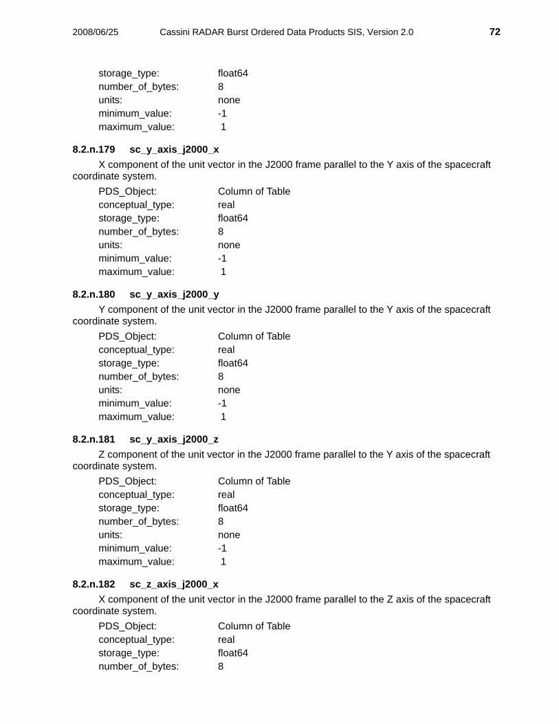
2008/06/25 Cassini RADAR Burst Ordered Data Products SIS, Version 2.0 72
storage_type: float64 number_of_bytes: 8 units: none minimum_value: -1 maximum_value: 1
8.2.n.179 sc_y_axis_j2000_x X component of the unit vector in the J2000 frame parallel to the Y axis of the spacecraft
coordinate system. PDS_Object: Column of Table conceptual_type: real storage_type: float64 number_of_bytes: 8 units: none minimum_value: -1 maximum_value: 1
8.2.n.180 sc_y_axis_j2000_y Y component of the unit vector in the J2000 frame parallel to the Y axis of the spacecraft
coordinate system. PDS_Object: Column of Table conceptual_type: real storage_type: float64 number_of_bytes: 8 units: none minimum_value: -1 maximum_value: 1
8.2.n.181 sc_y_axis_j2000_z Z component of the unit vector in the J2000 frame parallel to the Y axis of the spacecraft
coordinate system. PDS_Object: Column of Table conceptual_type: real storage_type: float64 number_of_bytes: 8 units: none minimum_value: -1 maximum_value: 1
8.2.n.182 sc_z_axis_j2000_x X component of the unit vector in the J2000 frame parallel to the Z axis of the spacecraft
coordinate system. PDS_Object: Column of Table conceptual_type: real storage_type: float64 number_of_bytes: 8

2008/06/25 Cassini RADAR Burst Ordered Data Products SIS, Version 2.0 73
units: none minimum_value: -1 maximum_value: 1
8.2.n.183 sc_z_axis_j2000_y Y component of the unit vector in the J2000 frame parallel to the Z axis of the spacecraft
coordinate system. PDS_Object: Column of Table conceptual_type: real storage_type: float64 number_of_bytes: 8 units: none minimum_value: -1 maximum_value: 1
8.2.n.184 sc_z_axis_j2000_z Z component of the unit vector in the J2000 frame parallel to the Z axis of the spacecraft
coordinate system. PDS_Object: Column of Table conceptual_type: real storage_type: float64 number_of_bytes: 8 units: none minimum_value: -1 maximum_value: 1
8.2.n.185 sc_x_axis_target_x X component of the unit vector in the target body frame parallel to the X axis of the
spacecraft coordinate system. Value is zero if target name is `NONE' or `CALIBRATION.' PDS_Object: Column of Table conceptual_type: real storage_type: float64 number_of_bytes: 8 units: none minimum_value: -1 maximum_value: 1
8.2.n.186 sc_x_axis_target_y Y component of the unit vector in the target body frame parallel to the X axis of the
spacecraft coordinate system. Value is zero if target name is `NONE' or `CALIBRATION.' PDS_Object: Column of Table conceptual_type: real storage_type: float64 number_of_bytes: 8 units: none minimum_value: -1

2008/06/25 Cassini RADAR Burst Ordered Data Products SIS, Version 2.0 74
maximum_value: 1
8.2.n.187 sc_x_axis_target_z Z component of the unit vector in the target body frame parallel to the X axis of the
spacecraft coordinate system. Value is zero if target name is `NONE' or `CALIBRATION.' PDS_Object: Column of Table conceptual_type: real storage_type: float64 number_of_bytes: 8 units: none minimum_value: -1 maximum_value: 1
8.2.n.188 sc_y_axis_target_x X component of the unit vector in the target body frame parallel to the Y axis of the
spacecraft coordinate system. Value is zero if target name is `NONE' or `CALIBRATION.' PDS_Object: Column of Table conceptual_type: real storage_type: float64 number_of_bytes: 8 units: none minimum_value: -1 maximum_value: 1
8.2.n.189 sc_y_axis_target_y Y component of the unit vector in the target body frame parallel to the Y axis of the
spacecraft coordinate system. Value is zero if target name is `NONE' or `CALIBRATION.' PDS_Object: Column of Table conceptual_type: real storage_type: float64 number_of_bytes: 8 units: none minimum_value: -1 maximum_value: 1
8.2.n.190 sc_y_axis_target_z Z component of the unit vector in the target body frame parallel to the Y axis of the
spacecraft coordinate system. Value is zero if target name is `NONE' or `CALIBRATION.' PDS_Object: Column of Table conceptual_type: real storage_type: float64 number_of_bytes: 8 units: none minimum_value: -1 maximum_value: 1

2008/06/25 Cassini RADAR Burst Ordered Data Products SIS, Version 2.0 75
8.2.n.191 sc_z_axis_target_x X component of the unit vector in the target body frame parallel to the Z axis of the
spacecraft coordinate system. Value is zero if target name is `NONE' or `CALIBRATION.' PDS_Object: Column of Table conceptual_type: real storage_type: float64 number_of_bytes: 8 units: none minimum_value: -1 maximum_value: 1
8.2.n.192 sc_z_axis_target_y Y component of the unit vector in the target body frame parallel to the Z axis of the
spacecraft coordinate system. Value is zero if target name is `NONE' or `CALIBRATION.' PDS_Object: Column of Table conceptual_type: real storage_type: float64 number_of_bytes: 8 units: none minimum_value: -1 maximum_value: 1
8.2.n.193 sc_z_axis_target_z Z component of the unit vector in the target body frame parallel to the Z axis of the
spacecraft coordinate system. Value is zero if target name is `NONE' or `CALIBRATION.' PDS_Object: Column of Table conceptual_type: real storage_type: float64 number_of_bytes: 8 units: none minimum_value: -1 maximum_value: 1
8.2.n.194 rot_vel_j2000_x X component of the spacecraft angular velocity vector in the J2000 frame. PDS_Object: Column of Table conceptual_type: real storage_type: float64 number_of_bytes: 8 units: rad/s
8.2.n.195 rot_vel_j2000_y Y component of the spacecraft angular velocity vector in the J2000 frame. PDS_Object: Column of Table conceptual_type: real

2008/06/25 Cassini RADAR Burst Ordered Data Products SIS, Version 2.0 76
storage_type: float64 number_of_bytes: 8 units: rad/s
8.2.n.196 rot_vel_j2000_z Z component of the spacecraft angular velocity vector in the J2000 frame. PDS_Object: Column of Table conceptual_type: real storage_type: float64 number_of_bytes: 8 units: rad/s
8.2.n.197 rot_vel_target_x X component of the spacecraft angular velocity vector in the target body frame. Value is
zero if target name is `NONE' or `CALIBRATION.' PDS_Object: Column of Table conceptual_type: real storage_type: float64 number_of_bytes: 8 units: rad/s
8.2.n.198 rot_vel_target_y Y component of the spacecraft angular velocity vector in the target body frame. Value is
zero if target name is `NONE' or `CALIBRATION.' PDS_Object: Column of Table conceptual_type: real storage_type: float64 number_of_bytes: 8 units: rad/s
8.2.n.199 rot_vel_target_z Z component of the spacecraft angular velocity vector in the target body frame. Value is
zero if target name is `NONE' or `CALIBRATION.' PDS_Object: Column of Table conceptual_type: real storage_type: float64 number_of_bytes: 8 units: rad/s
8.2.n.200 norm_cnt_rl Normalized radiometer resistive load measurement. PDS_Object: Column of Table conceptual_type: real storage_type: float32 number_of_bytes: 4

2008/06/25 Cassini RADAR Burst Ordered Data Products SIS, Version 2.0 77
units: counts/s minimum_value: 0 maximum_value: N/A
8.2.n.201 norm_cnt_nd Normalized radiometer noise diode measurement. PDS_Object: Column of Table conceptual_type: real storage_type: float32 number_of_bytes: 4 units: counts/s minimum_value: 0 maximum_value: N/A
8.2.n.202 norm_cnt_radio Normalized radiometer antenna measurement. PDS_Object: Column of Table conceptual_type: real storage_type: float32 number_of_bytes: 4 units: counts/s minimum_value: 0 maximum_value: N/A
8.2.3 Science Data Segment Fields
8.2.n.203 science_qual_flag Quality flag specifying which of the science data elements are valid. Zero value
indicates all data fields are valid. The meaning of a set bit (bit =1) is as follows for each bit. (Bit 0 is the LSB).
Bit 0 All passive mode fields are invalid. Bit 1 All active mode fields are invalid. Bit 2 All altimeter fields are invalid. Bit 3 All scatterometer fields are invalid. Bit 4 All radiometer fields are invalid. Bit 5 Passive boresight is not on surface. Bit 6 One or more of passive ellipse points is not on surface. Bit 7 Active boresight is not on surface. Bit 8 One or more of active ellipse points is not on surface.
PDS_Object: Column of Table conceptual_type: real storage_type: int32 number_of_bytes: 4 units: none minimum_value: 0

2008/06/25 Cassini RADAR Burst Ordered Data Products SIS, Version 2.0 78
maximum_value: N/A
8.2.n.204 system_gain Coefficient used to convert radiometer counts to antenna brightness temperature.
PDS_Object: Column of Table conceptual_type: real storage_type: float32 number_of_bytes: 4 units: dB
8.2.n.205 antenna_temp Antenna contribution to overall system temperature. PDS_Object: Column of Table conceptual_type: real storage_type: float32 number_of_bytes: 4 units: K
8.2.n.206 receiver_temp Internally generated receiver noise contribution to overall system temperature. PDS_Object: Column of Table conceptual_type: real storage_type: float32 number_of_bytes: 4 units: K
8.2.n.207 ant_temp_std Estimated standard deviation of the residual error in antenna temperature estimate. PDS_Object: Column of Table conceptual_type: real storage_type: float32 number_of_bytes: 4 units: K
8.2.n.208 pass_geom_time_offset Time offset from t_ephem_time for which passive geometry fields are computed. This time
is defined to be the mid-point of the summed radiometer windows. PDS_Object: Column of Table conceptual_type: real storage_type: float32 number_of_bytes: 4 units: s

2008/06/25 Cassini RADAR Burst Ordered Data Products SIS, Version 2.0 79
8.2.n.209 pass_pol_angle Angle of orientation of the electric field vector about the look vector during receipt of the
passive mode measurement. Angle is zero when the electric field vector is perpendicular to the plane of incidence as defined by the look vector and the target surface normal, and increases counterclockwise.
PDS_Object: Column of Table conceptual_type: real storage_type: float32 number_of_bytes: 4 units: deg
8.2.n.210 pass_emission_angle The angle between the antenna look direction and the surface normal during receipt of the
passive mode measurement. PDS_Object: Column of Table conceptual_type: real storage_type: float32 number_of_bytes: 4 units: deg
8.2.n.211 pass_azimuth_angle The direction of the projection of the antenna look vector in the plane tangent to the
surface at the measurement centroid, expressed by the angle counterclockwise from East (e.g. North is 90 degrees).
PDS_Object: Column of Table conceptual_type: real storage_type: float32 number_of_bytes: 4 units: deg
8.2.n.212 pass_centroid_lon Longitude of the passive (one-way) antenna boresight. PDS_Object: Column of Table conceptual_type: real storage_type: float32 number_of_bytes: 4 units: deg
8.2.n.213 pass_centroid_lat Latitude of the passive (one-way) antenna boresight. PDS_Object: Column of Table conceptual_type: real storage_type: float32 number_of_bytes: 4 units: deg

2008/06/25 Cassini RADAR Burst Ordered Data Products SIS, Version 2.0 80
8.2.n.214 pass_major_width Width of major axis of passive best fit ellipse, the distance along the map projection
reference sphere between point 1 and point 2. PDS_Object: Column of Table conceptual_type: real storage_type: float32 number_of_bytes: 4 units: km
8.2.n.215 pass_minor_width Width of minor axis of passive best fit ellipse, the distance along the map projection
reference sphere between point 3 and point 4. PDS_Object: Column of Table conceptual_type: real storage_type: float32 number_of_bytes: 4 units: km
8.2.n.216 pass_ellipse_pt1_lon Longitude of first point in ellipse representing passive measurement one-way 3-dB gain
pattern contour. This point is on the major axis of the best fit ellipse. Each point on the best fit ellipse is computed in the plane tangent to the surface at the boresight and then extended to the reference surface along the line of site of the antenna.
PDS_Object: Column of Table conceptual_type: real storage_type: float32 number_of_bytes: 4 units: deg
8.2.n.217 pass_ellipse_pt2_lon Longitude of second point in ellipse representing passive measurement one-way 3-dB gain
pattern contour. This point is on the major axis of the best fit ellipse. PDS_Object: Column of Table conceptual_type: real storage_type: float32 number_of_bytes: 4 units: deg
8.2.n.218 pass_ellipse_pt3_lon Longitude of third point in ellipse representing passive measurement one-way 3-dB gain
pattern contour. This point is on the minor axis of the best fit ellipse. PDS_Object: Column of Table conceptual_type: real storage_type: float32 number_of_bytes: 4 units: deg

2008/06/25 Cassini RADAR Burst Ordered Data Products SIS, Version 2.0 81
8.2.n.219 pass_ellipse_pt4_lon Longitude of fourth point in ellipse representing passive measurement one-way 3-dB gain
pattern contour. This point is on the minor axis of the best fit ellipse. PDS_Object: Column of Table conceptual_type: real storage_type: float32 number_of_bytes: 4 units: deg
8.2.n.220 pass_ellipse_pt1_lat Latitude of first point in ellipse representing passive measurement one-way 3-dB gain
pattern contour. This point is on the major axis of the best fit ellipse. PDS_Object: Column of Table conceptual_type: real storage_type: float32 number_of_bytes: 4 units: deg
8.2.n.221 pass_ellipse_pt2_lat Latitude of second point in ellipse representing passive measurement one-way 3-dB gain
pattern contour. This point is on the major axis of the best fit ellipse. PDS_Object: Column of Table conceptual_type: real storage_type: float32 number_of_bytes: 4 units: deg
8.2.n.222 pass_ellipse_pt3_lat Latitude of third point in ellipse representing passive measurement one-way 3-dB gain
pattern contour. This point is on the minor axis of the best fit ellipse. PDS_Object: Column of Table conceptual_type: real storage_type: float32 number_of_bytes: 4 units: deg
8.2.n.223 pass_ellipse_pt4_lat Latitude of fourth point in ellipse representing passive measurement one-way 3-dB gain
pattern contour. This point is on the minor axis of the best fit ellipse. PDS_Object: Column of Table conceptual_type: real storage_type: float32 number_of_bytes: 4 units: deg
2008/06/25 Cassini RADAR Burst Ordered Data Products SIS, Version 2.0 82
8.2.n.224 num_pulses_received Number of pulses which were received completely within the echo window. Partial pulses
are ignored. PDS_Object: Column of Table conceptual_type: real storage_type: float32 number_of_bytes: 4 units: none
8.2.n.225 total_echo_energy Estimate of the total energy in the receiver window in Joules. PDS_Object: Column of Table conceptual_type: real storage_type: float32 number_of_bytes: 4 units: J
8.2.n.226 noise_echo_energy Estimate of the noise contribution to the energy in the receiver window. PDS_Object: Column of Table conceptual_type: real storage_type: float32 number_of_bytes: 4 units: J
8.2.n.227 x_factor Ratio of received signal energy to normalized backscatter cross-section. PDS_Object: Column of Table conceptual_type: real storage_type: float32 number_of_bytes: 4 units: J
8.2.n.228 sigma0_uncorrected (sigma0) Normalized backscatter cross-section. Quantity is unitless. Scale is physical (linear) not
dB (logarithmic). PDS_Object: Column of Table conceptual_type: real storage_type: float32 number_of_bytes: 4 units: none

2008/06/25 Cassini RADAR Burst Ordered Data Products SIS, Version 2.0 83
8.2.n.229 sigma0_corrected Normalized backscatter cross-section corrected to minimize dependence on incidence
angle. Quantity is unitless. Scale is physical (linear) not dB (logarithmic). PDS_Object: Column of Table conceptual_type: real storage_type: float32 number_of_bytes: 4 units: none
8.2.n.230 sigma0_uncorrected_std Estimated standard deviation of residual error in normalized backscatter cross-section. PDS_Object: Column of Table conceptual_type: real storage_type: float32 number_of_bytes: 4 units: none
8.2.n.231 surface_height Estimated height of body surface above the center (reference point) determined from the
first moment of the compressed waveform after noise subtraction. The quantity is computed by subtracting the measured range to target from the spacecraft distance to body center from the ephemeris. No correction for off-nadir pointing is included. Computed from the active mode data when the radar is in altimeter mode. For other radar modes this data field is invalid, as indicated by science_qual_flag. This value corresponds to the PDS Data Dictionary element definition derived_planetary_radius.
PDS_Object: Column of Table conceptual_type: real storage_type: float32 number_of_bytes: 4 units: km
8.2.n.232 surf_ht_std Estimated uncertainty of the surface_height measurement based on the second central
moment of the noise-subtracted waveform distribution. This quantity is more a measure of signal spread and surface variation than of “noise” in the measurement itself.
PDS_Object: Column of Table conceptual_type: real storage_type: float32 number_of_bytes: 4 units: km
8.2.n.233 act_geom_time_offset Time offset from t_ephem_time for which active geometry fields are computed. This time
is defined to be the midway between the center of the transmit window and the center of the receive window.
PDS_Object: Column of Table

2008/06/25 Cassini RADAR Burst Ordered Data Products SIS, Version 2.0 84
conceptual_type: real storage_type: float32 number_of_bytes: 4 units: s
8.2.n.234 act_pol_angle Angle of orientation of the electric field vector about the look vector during the active mode
measurement. Angle is zero when the electric field vector is perpendicular to the plane of incidence as defined by the look vector and the target surface normal, and increases counterclockwise. Angle is determined for a time halfway between transmission and receipt of the active mode signal.
PDS_Object: Column of Table conceptual_type: real storage_type: float32 number_of_bytes: 4 units: deg
8.2.n.235 act_incidence_angle The angle between the antenna look direction and the surface normal halfway between
transmission and receipt of the active mode signal. PDS_Object: Column of Table conceptual_type: real storage_type: float32 number_of_bytes: 4 units: deg
8.2.n.236 act_azimuth_angle The direction of the projection of the antenna look vector in the plane tangent to the
surface at the measurement centroid expressed by the angle counterclockwise from East (e.g. North is 90 degrees).
PDS_Object: Column of Table conceptual_type: real storage_type: float32 number_of_bytes: 4 units: deg
8.2.n.237 act_centroid_lon Longitude of the active (two-way) antenna boresight. PDS_Object: Column of Table conceptual_type: real storage_type: float32 number_of_bytes: 4 units: deg
8.2.n.238 act_centroid_lat Latitude of the active (two-way) antenna boresight.

2008/06/25 Cassini RADAR Burst Ordered Data Products SIS, Version 2.0 85
PDS_Object: Column of Table conceptual_type: real storage_type: float32 number_of_bytes: 4 units: deg
8.2.n.239 act_major_width Width of major axis of active best fit ellipse, the distance along the map projection
reference sphere between point 1 and point 2. PDS_Object: Column of Table conceptual_type: real storage_type: float32 number_of_bytes: 4 units: km
8.2.n.240 act_minor_width Width of minor axis of active best fit ellipse, the distance along the map projection
reference sphere between point 3 and point 4. PDS_Object: Column of Table conceptual_type: real storage_type: float32 number_of_bytes: 4 units: km
8.2.n.241 act_ellipse_pt1_lon Longitude of first point in ellipse representing active measurement two-way 3-dB gain
pattern contour. This point is on the semi-major axis of the best fit ellipse. PDS_Object: Column of Table conceptual_type: real storage_type: float32 number_of_bytes: 4 units: deg
8.2.n.242 act_ellipse_pt2_lon Longitude of second point in ellipse representing active measurement two-way 3-dB gain
pattern contour. This point is on the semi-major axis of the best fit ellipse. PDS_Object: Column of Table conceptual_type: real storage_type: float32 number_of_bytes: 4 units: deg
8.2.n.243 act_ellipse_pt3_lon Longitude of third point in ellipse representing active measurement two-way 3-dB gain
pattern contour. This point is on the semi-minor axis of the best fit ellipse. PDS_Object: Column of Table
2008/06/25 Cassini RADAR Burst Ordered Data Products SIS, Version 2.0 86
conceptual_type: real storage_type: float32 number_of_bytes: 4 units: deg
8.2.n.244 act_ellipse_pt4_lon Longitude of fourth point in ellipse representing active measurement two-way 3-dB gain
pattern contour. This point is on the semi-minor axis of the best fit ellipse. PDS_Object: Column of Table conceptual_type: real storage_type: float32 number_of_bytes: 4 units: deg
8.2.n.245 act_ellipse_pt1_lat Latitude of first point in ellipse representing active measurement two-way 3-dB gain pattern
contour. This point is on the semi-major axis of the best fit ellipse. PDS_Object: Column of Table conceptual_type: real storage_type: float32 number_of_bytes: 4 units: deg
8.2.n.246 act_ellipse_pt2_lat Latitude of second point in ellipse representing active measurement two-way 3-dB gain
pattern contour. This point is on the semi-major axis of the best fit ellipse. PDS_Object: Column of Table conceptual_type: real storage_type: float32 number_of_bytes: 4 units: deg
8.2.n.247 act_ellipse_pt3_lat Latitude of third point in ellipse representing active measurement two-way 3-dB gain
pattern contour. This point is on the semi-minor axis of the best fit ellipse. PDS_Object: Column of Table conceptual_type: real storage_type: float32 number_of_bytes: 4 units: deg
8.2.n.248 act_ellipse_pt4_lat Latitude of fourth point in ellipse representing active measurement two-way 3-dB gain
pattern contour. This point is on the semi-minor axis of the best fit ellipse. PDS_Object: Column of Table conceptual_type: real

2008/06/25 Cassini RADAR Burst Ordered Data Products SIS, Version 2.0 87
storage_type: float32 number_of_bytes: 4 units: deg
8.2.n.249 altimeter_profile_range_start Range to the beginning of the buffer containing the altimeter profile. PDS_Object: Column of Table conceptual_type: real storage_type: float32 number_of_bytes: 4 units: km
8.2.n.250 altimeter_profile_range_step Difference in range between consecutive range bins in altimeter profile. PDS_Object: Column of Table conceptual_type: real storage_type: float32 number_of_bytes: 4 units: km
8.2.n.251 altimeter_profile_length Number of valid entries in altimeter profile. PDS_Object: Column of Table conceptual_type: integer storage_type: unint32 number_of_bytes: 4 units none minimum value: 0 maximum value: 32000
8.2.n.252 sar_azimuth_res Effective SAR image resolution along azimuth dimension. The value is the width on the
ground of a nominal Doppler bin (1bin width = 1/(pulse train duration)) for the current burst multiplied by a constant factor which depends on filter parameters used during azimuth compression.
PDS_Object: Column of Table conceptual_type: real storage_type: float32 number_of_bytes: 4 units: km

2008/06/25 Cassini RADAR Burst Ordered Data Products SIS, Version 2.0 88
8.2.n.253 sar_range_res Effective SAR image resolution along range dimension. The value is the width on the
ground of a nominal range bin (1bin width = speed of light/(chirp bandwidth)) for the current burst multiplied by a constant factor which depends on filter parameters used during range compression.
PDS_Object: Column of Table conceptual_type: real storage_type: float32 number_of_bytes: 4 units: km
8.2.n.254 sar_centroid_bidr_lon Longitude of the active (two-way) antenna boresight in the BIDR oblique cylindrical map
projection. PDS_Object: Column of Table conceptual_type: real storage_type: float32 number_of_bytes: 4 units: deg
8.2.n.255 sar_centroid_bidr_lat Latitude of the active (two-way) antenna boresight in the BIDR oblique cylindrical map
projection. PDS_Object: Column of Table conceptual_type: real storage_type: float32 number_of_bytes: 4 units: deg

2008/06/25 Cassini Radar Altimeter – ASCII File Description (Version 2 data) 89
9 Appendix D: ABDR Summary File (ASCII CSV) This Appendix describes the Altimeter ABDR Summary file which is created during altimeter processing to provide additional
information about the altimeter signal in an easy-to-use, stand-alone format (comma separated value, or CSV). Additional information about the altimeter data as of the generation of this document is also provided to help users understand the information in these data. Following the algorithm descriptions, a brief overview of the altimeter measurement is given.
File name structure: ABDR_SUMMARY_yy_Dzzz_Vnn.CSV, corresponding to the ABDR*.DAT, and the detached label is ABDR*.LBL, where
yy = Radar mode zzz = 3-digit Radar observation counter (unique through the mission) nn = 2-digit version number The structure of the Cassini Radar Altimeter ABDR Summary file is given in the following table. Each row in the file contains the 17 parameters listed in the table. Each row in the file represents one burst of data. All pulses within a burst are averaged before the parameters are derived. The algorithms for producing the items that are not copied from the LBDR are described following the table.
These data are Version 2. The format has been updated to allow predictable record lengths for the PDS SPREADSHEET
object. Data produced after January 1, 2008 use the new Radar-determined Titan pole location.
Parameter Method Units Format Algorithm
SAB Counter Copy from LBDR Count Integer (I9)
Spacecraft Event Time (UTC) for beginning of burst Copy from LBDR None
UTC yyyy-mm-ddThh:mm:ss.ss
s
Time from closest approach Copy from LBDR sec Float (F8.2)
Range to antenna boresight intercept with surface
First moment of waveform. Not corrected for off-nadir pointing.
meter Integer (F8.0) Note: used in surface height correction
Active Centroid Longitude (west 0-360) Copy from LBDR deg Float (F7.2)

2008/06/25 Cassini Radar Altimeter – ASCII File Description (Version 2 data) 90
Parameter Method Units Format Algorithm
Active Centroid Latitude Copy from LBDR deg Float (F7.2)
Threshold surface height From threshold range detection meter Integer (I8) Algo 1 (from center, so ~2575000)
MLE surface height MLE estimate of surface height meter Integer (I8) Algo 8
First moment surface height From first moment of waveform range (Range to Surface) meter Integer (I8) Algo 2 (In ABDR field
surface_height) Corrected first moment surface height
First moment height corrected for off-nadir angle and altitude meter Integer (I8) Algo 3
Corrected threshold surface height
Threshold height corrected for off-nadir angle and altitude meter Integer (I8) Algo 4
Height span of backscatter Distribution (“depth”)
Square root of the second central moment meter Integer (I8) Algo 5 (In ABDR field
surf_ht_std) Skewness of backscatter distribution
Third central moment normalized dimensionless Float (F8.2) Algo 6
Incidence angle Copy from LBDR degrees Float (F8.3)
Sigma0 Calibrated MLE amplitude estimate dB Float (F8.2) Algo 9 (see note)
SNR Ratio of peak to estimated noise backscatter value dB Float (F8.2) Algo 7
MLE fit quality Difference between data and model % Float (F8.2) Final value of err_ML in algo
8

2008/06/25 Cassini Radar Altimeter – ASCII File Description (Version 2 data) 91
Algo 1: Threshold Detected Surface Height Data samples are shifted to put the maximum value at the middle of the received window (1000 points). A noise level is computed as the average over the first 200 samples. The threshold bin is the first sample > 15 times the noise level. The total range is computed by transforming bin with altimeter constants and resolving the range ambiguity. The corresponding Titan surface height is found without taking into account the slant geometry for the computed incidence
angle (see Corrected Threshold Surface Height).
Algo 2: First Moment Surface Height Data samples are shifted to put the maximum value at the middle of the received window (1000 points). A noise level is computed as the average over the first 200 samples. All values < 10 * noise are put to zero (if 10 * noise is > max(data) the threshold 10 * noise is iteratively reduced by dividing
by 2). The first moment bin is estimated as Sum( bin*value ) / Sum( value ). The total range is computed by transforming bin with altimeter constants and resolving the range ambiguity. The corresponding Titan surface height is found without taking into account the slant geometry for the computed incidence
angle (see Corrected First Moment Surface Height). (This value corresponds to the PDS Data Dictionary element definition derived_planetary_radius.)
Algo 3: Corrected First Moment Surface Height The first moment height is corrected for spacecraft range to surface and off-nadir pointing effects based on simulations
including surface curvature and RMS surface height over the altimeter footprint as it varies with range.
Algo 4: Corrected Threshold Surface Height The threshold height is corrected for spacecraft range to surface and off-nadir pointing effects based on simulations
including surface curvature and RMS surface height over the altimeter footprint as it varies with range.
Algo 5: Height Span (Depth) – Square root of second central moment Data samples are shifted to put the maximum value at the middle of the received window (1000 points). A noise level is computed as the average over the first 200 samples. All values < 10 * noise are put to zero (if 10 * noise is > max(data) the threshold 10 * noise is iteratively reduced by dividing
by 2). Bin values relative to the first moment (bin_c) are used to estimate the second moment bin as Sum( bin_c^2*value ) / Sum(
value ). The second moment range is computed by transforming this bin with altimeter constants.

2008/06/25 Cassini Radar Altimeter – ASCII File Description (Version 2 data) 92
Algo 6: Height Skewness – Normalized third central moment Data samples are shifted to put the maximum value at the middle of the received window (1000 points). A noise level is computed as the average over the first 200 samples. All values < 10 * noise are put to zero (if 10 * noise is > max(data) the threshold 10 * noise is iteratively reduced by dividing
by 2). Bin values relative to the first moment (bin_c) are used to estimate the third moment bin as Sum( bin_c^3*value ) / Sum(
value ). The third moment range is computed by transforming this bin with altimeter constants. The value is normalized by dividing by the second moment raised to the 1.5 power.
Algo 7: Signal to Noise Ratio Data samples are shifted to put the maximum value at the middle of the received window (1000 points). A noise level is computed as the average over the first 200 samples. MAX = maximum of data values. The SNR value is found: SNR=10*log10(MAX/noise) .
Algo 8: Maximum Likelihood Estimate of Height A model of the expected return for the Cassini altimeter pulse for the given off-nadir angle and RMS surface height distribution is fit to the observed values with an iterative Maximum Likelihood Estimator (MLE). The procedure is widely used in processing ocean altimeter data such as TOPEX and Jason-1. The resulting estimates are usually comparable to the first moment estimates. The algorithm can be confused if the observed pulse is significantly different (e.g., double-peaked) from the assumed model. The solutions intrinsically correct for range and off-nadir effects that must be explicitly corrected for the threshold and first moment estimates. A complete description of this processing is in press for publication in Transactions on Geoscience and Remote Sensing (Alberti et al).

2008/06/25 Cassini Radar Altimeter – ASCII File Description (Version 2 data) 93
Algo 9: Backscatter (sigma0) Estimate Constants & definitions: k=1.38e-23 B = transmitted signal bandwidth G0 = antenna gain 53.1 dB sigma_p = sqrt(1/log(2)/8)/B PT = peak transmitted power (48.084 W) Lambda = transmitted central wavelength T = transmitted pulse length For each fly-by calibration data are processed (ALTH mode). Data with antenna calibration source are used (csr = 1): to give noise_antenna_mean = mean of power detected data ATT_cal = value of attenuation used during acquisition of antenna data. Using system temperature test data (L1=-27 and T1 = 814, L2=-31 and T2=956), the two parameters for the linear
approximation of system temperature are found: b=(T2-T1)/(L2-L1) ; a=T1-b*L1 The system temperature during calibration is found: T_sys = a + b*10*log10(ATT_cal) The calibration constant is found: C = k*B*T_sys/ noise_antenna_mean*ATT_cal The final value of AMP output of the MLE method (see algo 8) is used to evaluate the final sigma0: K=(G0^2) * (lambda^2) * c / 2 / ((4*pi)^2) ./ (H^3) * PT .* B .* T .* pi .* sigma_p sigma_0 = 2./ATT.*AMP*C/K, where ATT = attenuation value used. NOTE: The AMP value is the amplitude estimate from the MLE. For waveforms that do not conform to the pulse model
used in the MLE, the amplitude estimate may not be a good representation of the total backscatter. In particular, for multi-peaked or diffuse waveforms, this value will underestimate the total return power. The SBDR and LBDR files contain a backscatter estimate from the scatterometer processing which does include all returned power.

2008/06/25 Cassini Radar Altimeter – ASCII File Description (Version 2 data) 94
Overview of Cassini Radar Altimetry The Cassini RADAR instrument is described in detail in Elachi et al. (2004). The central antenna beam (Beam 3 for SAR)
of Cassini’s 4-m high gain antenna is roughly circular, with a full-width half maximum of 0.35 degrees (6 milliradians). This beam is used for non-SAR observations, including altimetry. Altimetry is performed with the beam pointed at nadir, and thus altimetry data is confined to short segments of the spacecraft ground track. Typical altimeter observations (“tracks”) are 300 to 600 km long. A unique observation was obtained on T30 that was about 3500 km long, much of it over the T28 SAR image swath.
The raw altimeter data product is an echo profile – intensity versus propagation time delay referenced to the spacecraft clock –
resulting from matched filter processing (“compressing”) 10-MHz samples of the frequency-encoded (“chirped”, 4.2-MHz bandwidth) pulse to give one-way range resolution of 30 m (“range bin”). Time delay is determined from the echo profile as described above in algorithms 1, 2, 8. The delay corresponds (via a factor of two and the speed of light) to the range to the target. Data are taken in bursts of pulses (typically 15) separated by 1-3 seconds. Determining the surface height relative to a reference point (in this case the center of mass) also depends upon an independent measurement of the position of the point relative to the altimeter. The Cassini-Titan distance is found using the ephemeris determined by the project navigation team. The Cassini-Titan distance is reconstructed after a flyby to an accuracy of better than 100 m. As noted in Section 2.3.2, the spacecraft position and velocity vectors are obtained at the start time of the burst (t_ephem_time). The geometry for altimeter data is calculated at
t_ephem_time + act_geom_time_offset. Users can compute the spacecraft position at this time using values of the position and velocity in an equation shown
generically as new_sc_pos = sc_pos + act_geom._time_offset * sc_vel
where sc_pos and sc_vel are in the desired coordinate system and the equation applies to each component of the position. Performing this position update is crucial to using the altimeter data (but as noted, it is already done for the altimeter bursts).
The echo profile is defined by the surface radar backscatter cross section as a function of range weighted by the antenna
beam pattern. If the beam is not directed vertically (at nadir), the estimated range may not correspond exactly to the altitude. The spacecraft attitude is maintained near nadir-pointing by Cassini’s attitude control system. The beam nominally intersects the surface within about 2 milliradians (0.12 degrees, approximately 1/3 of a beam width) of nadir. For the early flybys Ta and T3 when the Titan ephemeris, and thus the relative position of the spacecraft and Titan, was less well-known, the off-nadir angle was somewhat larger than 2 milliradians (mrad). The error from these variations is corrected above in algorithms 3, 4. For off-nadir angles greater than the nominal ~1 mrad, the error grows rapidly.
For locally flat surfaces with ample signal to noise like the Earth’s oceans, modeling of the altimeter return in the pulse-
limited case using the Brown model (Brown, 1977) can yield range resolutions of better than 0.1 of the nominal range resolution. The

2008/06/25 Cassini Radar Altimeter – ASCII File Description (Version 2 data) 95
early observations of Titan suggested that this model could be applicable to the data so that using the Brown model in a Maximum Likelihood Estimator (MLE) the range could have a precision of a few meters. Unfortunately, later data have shown that the pulses are sometimes more complex than predicted by the Brown model. Improved MLE fits require a better pulse model. The MLE algorithm for single peaked waveforms gives a height estimate similar to that from the first moment. Single peak waveforms occur over most of Titan, the main exception being the brightest, apparently hilly and complex areas.
The figure below shows a “radargram” – signal strength vs height above the center of Titan for T30. As noted above, T30
was unique in being a very long track of altimeter data (about 3500 km) over the T28 SAR swath. The track goes from a typical altimeter altitude of 10,000 km above the surface to closest approach at approximately 1000 km. At the lower altitude the antenna footprint becomes much smaller (~6 km rather than ~60 km) providing improved spatial resolution. The second figure below shows the end of the track (the right edge of the first figure – the along track scales are centered at different places).

2008/06/25 Cassini Radar Altimeter – ASCII File Description (Version 2 data) 96

2008/06/25 Cassini Radar Altimeter – ASCII File Description (Version 2 data) 97
The T30 altimeter track provided significant insight into the altimeter data. The main conclusion was that the much of the return width, or “depth,” seen in the radargrams is sub-footprint surface height variation. With this understanding, simulations with RMS surface height variations of approximately 100-200 m and including surface curvature and off nadir pointing are able to reproduce many of the characteristics of the radargrams. After additional analysis, it was decided to include the signal second central moment and the skewness – the third moment normalized by the second moment as shown in algorithm 6 – to provide numerical data to represent the depth and complexity seen in the radargrams. As can be seen below, there is small-scale information, usually much smaller scale than the antenna footprint, that cannot be easily conveyed by statistics. Thus, the data in the ASCII file provide a starting point for understanding the altimeter data; but much additional information can be obtained from the waveforms in the ABDR.

2008/06/25 Cassini Radar Altimeter – ASCII File Description (Version 2 data) 98
References Alberti, G., L. Festa, C. Papa, and G. Vingione (2008), “A Waveform Model for Near-nadir Radar Altimetry Applied to the
Cassini Mission to Titan”, IEEETrans. Geosci. Remote Sensing, in press Brown, G.S. (1977), “The average impulse response of a rough surface and its application,” IEEE Transactions on Antenna
and Propagation, AP 25(1), 67-74. Elachi, C.; Allison, M. D.; Borgarelli, L.; Encrenaz, P.; Im, E.; Janssen, M. A.; Johnson, W. T. K.; Kirk, R. L.; Lorenz, R. D.;
Lunine, J. I.; Muhleman, D. O.; Ostro, S. J.; Picardi, G.; Posa, F.; Rapley, C. G.; Roth, L. E.; Seu, R.; Soderblom, L. A.; Vetrella, S.; Wall, S. D.; Wood, C. A.; Zebker, H. A. (2004), RADAR: “The Cassini Titan Radar Mapper,” Space Science Reviews, 115, Issue 1-4, 71-110.
Zebker, H.A., Y. Gim, P. Callahan, S. Hensley, R. Lorenz (2008), “Analysis and Intepretation of Cassini Titan Radar Altimeter Echoes”, submitted to Icarus.