Cashpower Prepayment Metering Cashpower Gemini HMI … HMI (35).pdf · Cashpower Gemini HMI –...
35
Cashpower Gemini HMI – Version 11 Firmware Cashpower Prepayment Metering Cashpower Gemini HMI User Guide Document version: 0.0 Date: 14 th December 2011 Issued by Product Management: Dave Tarr © 2011 Landis+Gyr (Pty) Ltd Electricity Prepayment Meters Residential
Transcript of Cashpower Prepayment Metering Cashpower Gemini HMI … HMI (35).pdf · Cashpower Gemini HMI –...

C ash p ow er G emin i H MI – V ers i on 1 1 F i r mwar e
Cashpower Prepayment Metering
Cashpower Gemini HMI
User Guide
Document version: 0.0
Date: 14th December 2011
Issued by Product Management: Dave Tarr
© 2011 Landis+Gyr (Pty) Ltd
Electricity Prepayment Meters
Residential

2/35 Released Introduction
© Landis+Gyr (Pty) Ltd Cashpower Gemini HMI – User Guide
Revision history
Version Date Originator Comments
0.0 14/12/2011 Dave Tarr First Release

Introduction Released 3/35
Cashpower Gemini HMI – User Guide © Landis+Gyr (Pty) Ltd
Table of Contents
1 Introduction______________________________________________________________________ 6
2 Human-Machine Interface (Meter)____________________________________________________ 7
3 Customer Interface Unit (CIU) _______________________________________________________ 8
4 Liquid Crystal Display Indications __________________________________________________ 10
4.1 Load switch Status Indicator _____________________________________________________ 11
4.2 Alarm Indicator ________________________________________________________________ 11
4.3 Remaining Credit Indicator ______________________________________________________ 11
4.4 Information Indicator ___________________________________________________________ 11
4.5 Currency Indicator _____________________________________________________________ 12
4.6 Power (kWh) Indicator __________________________________________________________ 12
4.7 Happy and Sad Faces __________________________________________________________ 12
5 LED Indicators __________________________________________________________________ 13
5.1 Rate of Consumption Indicator (Rate LED) __________________________________________ 13
5.2 Alarm LED (Customer Interface Unit Only) __________________________________________ 13
6 Optical Communications Port (Meter only) ___________________________________________ 14
7 General Meter Operation __________________________________________________________ 15
7.1 Entering tokens via the keypad ___________________________________________________ 16
7.2 Token Processing _____________________________________________________________ 16 7.2.1 Incomplete Token ___________________________________________________________ 16 7.2.2 Complete Token ____________________________________________________________ 16
7.2.2.1 Token Accepted _________________________________________________________ 16 7.2.2.2 Token Accepted as a Valid Key Change Number _______________________________ 16 7.2.2.3 Token Overflow Rejection _________________________________________________ 17 7.2.2.4 Incorrect Token __________________________________________________________ 17 7.2.2.5 Duplicate Token _________________________________________________________ 17 7.2.2.6 Expired Token___________________________________________________________ 17
7.3 Token Decryption and Processing _________________________________________________ 17 7.3.1 Electricity Credit Token _______________________________________________________ 18 7.3.2 Set 1st Dispenser Key Token __________________________________________________ 18 7.3.3 Set 2nd Dispenser Key Token __________________________________________________ 18 7.3.4 Clear Tamper Token _________________________________________________________ 18 7.3.5 Set Power Limit Token _______________________________________________________ 18 7.3.6 Set Credit Levels Token ______________________________________________________ 18 7.3.7 Clear Credit Token __________________________________________________________ 18 7.3.8 Initiate Dispenser Test Token (Non Meter-Specific Token) ___________________________ 19 7.3.9 Commissioning Token (Non Meter-Specific Token) _________________________________ 19 7.3.10 Commissioning Token (Meter-Specific Token) _____________________________________ 19 7.3.11 Decommissioning Token (Meter-Specific Token) ___________________________________ 19 7.3.12 Set Credit Metering Mode (Meter-Specific Token) __________________________________ 19 7.3.13 Set Prepayment Metering Mode (Meter-Specific Token) _____________________________ 19 7.3.14 Set Energy Limiting Mode (Meter-Specific Token) __________________________________ 20 7.3.15 Set DAE Value (Meter-Specific Token) ___________________________________________ 20 7.3.16 Force Load Switch Open (Meter-Specific Token) ___________________________________ 20
7.4 Commissioning and Decommissioning the Meter _____________________________________ 20
7.5 Power Limiting ________________________________________________________________ 20

4/35 Released Introduction
© Landis+Gyr (Pty) Ltd Cashpower Gemini HMI – User Guide
7.6 Reverse Power Detection and Metering ____________________________________________ 21
7.7 Automatic/Manual Load Reconnection _____________________________________________ 21
7.8 Disconnect on Power Failure ____________________________________________________ 21
7.9 Optical Port __________________________________________________________________ 21
7.10 Credit Reader Interface _________________________________________________________ 21
8 Anti-tamper Features ____________________________________________________________ 22
8.1 General _____________________________________________________________________ 22
8.2 Anti-Tamper Switch ____________________________________________________________ 22
8.3 Reverse Energy Detection ______________________________________________________ 22
8.4 Resetting a Tamper Condition ___________________________________________________ 22
9 Meter Operation (Prepayment Metering Mode) _______________________________________ 23
10 Meter Operation (Credit Metering Mode)_____________________________________________ 24
11 Meter Operation (Energy Limiting Mode) ____________________________________________ 25
11.1 Daily Allocation of Energy (DAE) _________________________________________________ 25
11.2 Operation ___________________________________________________________________ 25
11.3 Alarms ______________________________________________________________________ 26
12 Customer Interface Unit - Specific Functions ________________________________________ 28
12.1 General _____________________________________________________________________ 28
12.2 Audible Low-Credit Alarm _______________________________________________________ 28
12.3 Other Audible Tones ___________________________________________________________ 28
13 Information Functions____________________________________________________________ 29
13.1 Meter Number (Register 000) ____________________________________________________ 30
13.2 Instantaneous Power (Register 001) ______________________________________________ 30
13.3 Current Credit Register – 0.1kWh Resolution (Register 002) ____________________________ 30
13.4 Total Units Counter – 0.1kWh Resolution (Register 003) _______________________________ 30
13.5 DAE Accumulated Credit Register – 0.001kWh Resolution (Register 004) _________________ 30
13.6 Current 24-Hour Consumption (Register 006) _______________________________________ 30
13.7 Previous 24-Hour Consumption (Register 007) ______________________________________ 30
13.8 Current 30-Day Consumption (Register 008) ________________________________________ 30
13.9 Previous 30-Day Consumption (Register 009) _______________________________________ 30
13.10 DAE Value – 0.01kWh Resolution (Register 011) ____________________________________ 30
13.11 Low Credit Level (Register 012) __________________________________________________ 31
13.12 High Credit Level (Register 013)__________________________________________________ 31
13.13 Power Limit Level (Register 014) _________________________________________________ 31
13.14 Extended Meter Number (Register 024) ____________________________________________ 31
13.15 Scrolling Meter Number (Register 025) ____________________________________________ 31
13.16 Meter (Fixed) State Register 1 (Register 030) _______________________________________ 31
13.17 Meter (Fixed) State Register 0 (Register 031) _______________________________________ 32
13.18 Meter (Changeable) Option Register 0 (Register 035) _________________________________ 32
13.19 Meter (Display) State Register 0 (Register 037) ______________________________________ 33
13.20 Software Version Number (Register 048) ___________________________________________ 33
13.21 Power-Fail Counter (Register 050) ________________________________________________ 33
13.22 Last Token ID in Date/Time Format (Register 054) ___________________________________ 33
13.23 Identifier of Last Token Entered (Register 055) ______________________________________ 33

Introduction Released 5/35
Cashpower Gemini HMI – User Guide © Landis+Gyr (Pty) Ltd
13.24 Value of Last Token Entered (Register 056) _________________________________________ 33
13.25 Key Revision and Key Type (Register 057) __________________________________________ 33
13.26 Tariff Index (Register 058) _______________________________________________________ 33
13.27 Current Credit Register – 0.001kWh Resolution (Register 059) __________________________ 33
13.28 Supply Group Code (SGC) Register (Register 060) ___________________________________ 33
13.29 Total Units Counter – 0.001kWh Resolution (Register 061) _____________________________ 34
13.30 Current Credit Register – 0.000001kWh Resolution (Register 062) _______________________ 34
13.31 DAE Accumulated Credit Register – 0.000001kWh Resolution (Register 063) ______________ 34
13.32 DAE 15-Second Portion Register – 0.000001kWh Resolution (Register 064) _______________ 34
13.33 Low Credit Level – 0.000001kWh Resolution (Register 065) ____________________________ 34
13.34 Latch Inhibit Timer – 1-Minute Resolution (Register 066) _______________________________ 34
14 Error Codes _____________________________________________________________________ 35
14.1 Meter _______________________________________________________________________ 35
14.2 Customer Interface Unit _________________________________________________________ 35

6/35 Released Introduction
© Landis+Gyr (Pty) Ltd Cashpower Gemini HMI – User Guide
1 Introduction
Cashpower Gemini HMI is part of the Gemini family of prepayment meters and is a single-phase, keypad-based, stand-alone or split prepayment electricity meter in a British Standard housing. If used as a split prepayment meter, it comprises two parts, namely the meter and the customer interface unit.
The Gemini MMI can be used as a stand-alone prepayment meter, typically installed inside the household, or can be used as a split prepayment meter by simply connecting the customer interface unit, which will then be the customer‟s only interface with the meter.
When used as a split metering solution, the meter is usually installed in a secure, locked enclosure, typically a pavement kiosk or pole-mounted equivalent. The customer interface unit is usually installed in a convenient location in the consumer‟s home - remote from the meter and is connected to the meter with a pair of communications wires.
Figure 1: Customer Interface Unit
Figure 2: Gemini HMI Split Prepayment Meter

Human-Machine Interface (Meter) Released 7/35
Cashpower Gemini HMI – User Guide © Landis+Gyr (Pty) Ltd
2 Human-Machine Interface (Meter)
Figure 3: Meter typical front panel features
Rate of Consumption Indicator (Rate LED): This red LED provides both a visual indication of instantaneous power consumption as well as the reference output for verifying the meter‟s metrological accuracy.
Optical Communications Port: This port enables data to be transferred to and from the meter (e.g. the accessing of various registers or downloading of new parameters) using a portable interrogation device. The optical port‟s communication protocol complies with IEC 62056-21 Mode C.
LCD Display. Large custom LCD with language independent icons
Keypad: The meter has a 12-key non tactile keypad with audible feedback. The keypad is used for entry of tokens and accessing various management functions and meter parameters via the information mode. The keypad also has a backspace key.
Rate of consumption indicator (rate LED) 1000 pulses/kWh
Backspace Key In case of consumer key press
error
Optical communications port
Meter label Each meter has a unique identity label
printed at the time of manufacture
LCD Display With language independent icons
Keypad 12-key keypad with audible
feedback for key presses
Terminal Cover Supplied with short or long
terminal cover depending on utility requirements
Sealing Screw Use of utility sealing wires shows visible signs of
tampering
Information Key For entering the information mode to read
meter parameters

8/35 Released Customer Interface Unit (CIU)
© Landis+Gyr (Pty) Ltd Cashpower Gemini HMI – User Guide
3 Customer Interface Unit (CIU)
Figure 4: Customer Interface Unit front panel indications
The customer interface unit comprises a non-tactile, 12-key keypad with audible feedback (for the entry of tokens and accessing of various management functions), and a custom LCD (for the display of remaining credit, the scrolling in of keypad entries and various meter status and management functions).
A red rate of consumption LED provides a visual indication of instantaneous power consumption.
The rate LED on the customer interface unit is not a reference output and may not
be used for verifying the associated meter‟s metrological accuracy.
A yellow alarm LED indicator duplicates the alarm indication function on the LCD. Its main function is to give a visible indication of low credit levels.
The customer interface unit is effectively a remote display and keypad for the meter. Communications between the two units takes place in real time e.g. keypad entries at the customer interface unit are processed by the meter and echoed to the customer interface unit display.
Rate of consumption indicator (rate LED)
Liquid Crystal Display With language independent
icons
Associated meter serial number (Connected to this unit)
12-key keypad
Alarm indicator Indicates low credit (Visual & Audible)
Information key (For entering into information mode to
read meter
parameters)
Backspace key In case of consumer key press error

Customer Interface Unit (CIU) Released 9/35
Cashpower Gemini HMI – User Guide © Landis+Gyr (Pty) Ltd
Figure 5: Customer Interface Unit - Rear View

10/35 Released Liquid Crystal Display Indications
© Landis+Gyr (Pty) Ltd Cashpower Gemini HMI – User Guide
4 Liquid Crystal Display Indications
The LCD is designed to give a clear and unambiguous visual indication of the important meter functions by means of language-independent pictograms:
Figure 6: What the ICONS mean
Figure 7: Operational Displays
1 - Happy face
2 - Sad Face
3 - Alarm indicator
4 - Load switch status indicator
5 - Remaining credit indicator
6 - Information mode
7 - Currency function
8 - Power (kWh) function
9 - Not used
10 - Eight X 7 segment digits
Normal Operation
Zero Credit
Display shows remaining credit (kWh).
Load switch closed and consumption rate indicator flashes at a rate proportional to the power being used.
Credit running low and more needs to be purchased to avoid disconnection of supply.
Supply disconnected.
Low Credit Warning
Power Limit Lockout Supply disconnected.
Energy Limiting
Mode
Display shows the amount of accumulated energy currently available. The credit wedge will always be scrolling – up, if energy credit is accumulating, or down, if it is decreasing.
Scrolling wedge

Liquid Crystal Display Indications Released 11/35
Cashpower Gemini HMI – User Guide © Landis+Gyr (Pty) Ltd
4.1 Load switch Status Indicator
This icon indicates the status of the meter‟s internal load control switch.
Under normal operating conditions i.e. with the meter in credit, the load switch will be „closed‟ and power supplied to the consumer. It will „open‟ when credit expires.
4.2 Alarm Indicator
This is a „low credit‟ warning indicator that turns on if the remaining credit value is greater than zero, but less than half the low credit level programmed into the meter. Under these conditions it is displayed in conjunction with the smallest credit wedge icon on the LCD.
4.3 Remaining Credit Indicator
This „wedge‟ provides a quick visual indication of the remaining credit in the meter and functions as follows:
Displays all four credit wedge icons if the credit register is greater than, or equal to, the high credit level.
Displays the three smallest credit wedge icons if the credit register is greater than, or equal to, the low credit level but less than the high credit level.
Displays the two smallest credit wedge icons if the credit register is greater than or equal to half the low credit level, but less than the low credit level.
Displays the smallest credit wedge LCD icon if the credit register is greater than zero, but less than half the low credit level.
If the remaining credit is less than or equal to zero, all the credit wedge icons will be off.
When the remaining credit level reaches zero, the numeric display indicates 0.0kWh. If, for any reason, the credit level is decremented below zero i.e. negative, the display indicates 0. kWh. This is the case if the meter has been personalised not to display negative credit. Although there is no negative value displayed, it gives a quick visual indication that a negative value is present.
The Remaining Credit Indicator‟s function varies slightly, depending on which mode the meter is operating in.
In prepayment mode, the wedge segments toggle at pre-defined (token-settable) credit levels.
In energy limiting mode, the wedge icons are continuously scrolling from either left to right or right to left. If the amount of energy being consumed by the connected load is less than the rate at which energy credit (DAE) is being added i.e. the overall energy credit level in the meter is increasing, it scrolls from left to right. If the amount of energy being consumed by the connected load is more than the rate at which energy credit (DAE) is being added i.e. the overall energy credit level in the meter is decreasing, it scrolls from right to left.
The rate at which energy credit is added depends on the value of the DAE. This value is typically set to zero at the time of manufacture and can then be set to any value with an appropriate engineering token from the prepayment vending system at the time of installation.
4.4 Information Indicator
This icon turns on in response to pressing the information key on the keypad. It indicates that the meter is in information mode and the contents of various registers can be viewed.

12/35 Released Liquid Crystal Display Indications
© Landis+Gyr (Pty) Ltd Cashpower Gemini HMI – User Guide
4.5 Currency Indicator
This icon is turned on when the meter is in the Credit Mode.
4.6 Power (kWh) Indicator
This function is used whenever the displayed units represent power (kWh). It applies to both normal meter operation as well as when viewing registers via the information mode.
The power (kWh) icon will also flash at a rate of 1flash per second if no energy is being consumed i.e. if the meter is in creep lock.
4.7 Happy and Sad Faces
These two icons are used in combination to give a quick visual indication of good and bad status. For example, if the meter were operating normally, the happy face would be on. However, if it were to be tampered, the sad face would come on. Similar responses would apply during token entry e.g. entering an invalid Credit Transfer Number would result in the sad face flashing for a short period of time.

LED Indicators Released 13/35
Cashpower Gemini HMI – User Guide © Landis+Gyr (Pty) Ltd
5 LED Indicators
5.1 Rate of Consumption Indicator (Rate LED)
The rate at which energy is being consumed is indicated via the red rate LED. This is the reference output for determining the meter‟s metrological accuracy. It also gives a quick visual indication of electricity usage e.g. a fast rate when a stove is in use and a large amount of electricity being consumed.
The meter constant for Gemini HMI meter is set to 1000 impulses/kWh. The rate LED will therefore flash 1000 times for every kWh of energy consumed.
The rate LED on the customer interface unit is not a reference output and may not be used for verifying the associated meter‟s metrological accuracy.
5.2 Alarm LED (Customer Interface Unit Only)
On the Customer Interface Unit, the alarm indicator functionality of the LCD is duplicated on a flashing yellow LED to give a very clear visual indication to the consumer that the credit level is low and disconnection of the electricity supply could occur soon.

14/35 Released Optical Communications Port (Meter only)
© Landis+Gyr (Pty) Ltd Cashpower Gemini HMI – User Guide
6 Optical Communications Port (Meter only) This port enables data to be transferred to and from the meter (e.g. the accessing of various registers or downloading of new parameters).

General Meter Operation Released 15/35
Cashpower Gemini HMI – User Guide © Landis+Gyr (Pty) Ltd
7 General Meter Operation It is possible to switch the meter between any one of its three modes of operation at any stage via engineering tokens generated by the prepayment vending system.
Display and control functions common to all modes of operation are described in this section. Mode-specific functions are described in subsequent sections.
Figure 8: Entering tokens into the keypad of the meter
Figure 9: Typical displays
Normal operating mode
(includes zero credit and supply disconnected)
Number not recognized by meter
Number already used
Not enough digits entered
(30 second timeout)
Service call-out
Number expired
Power off
Meter tampered
Normal operating mode (Includes zero credit and supply disconnected)
Number not recognized by meter
Number already used Not enough digits entered (30-second timeout)
Meter Tampered
Service callout
Number expired
Service callout
Enter the 20 digit number as it appears on the token, into the meter via the keypad. An audible „beep‟ is heard on each key press. Incorrect entries can be corrected with the backspace key. Incomplete number entries will be cleared after 30 seconds. After entering a complete, valid number, the new credit total is displayed.

16/35 Released General Meter Operation
© Landis+Gyr (Pty) Ltd Cashpower Gemini HMI – User Guide
7.1 Entering tokens via the keypad
Tokens such as credit, set power limit and tamper reset, are entered into the meter by keying in the numbers printed on the token via the keypad. The numbers entered are displayed on the LCD as they are being entered and scroll from right to left, with a decimal point displayed at every fourth digit for ease of viewing.
Visual feedback is provided by flashing the happy face icon with each key press.
Audible feedback is provided by a „beep‟ on each key press.
Incorrect entries can be corrected with the backspace key, which removes the rightmost digit on the LCD with each key press. Two backspace key presses in quick succession will clear the entire entry.
Acceptance of a valid token is automatic. Once a complete token has been entered, the meter processes it and, depending on the result, displays one of the sequences described in – refer section 7.2. Again, depending on what sequence is invoked, the keypad could remain locked for a variable period of time i.e. it will not respond in any way to further key presses.
An incomplete token entry will be timed-out after 30 seconds; where after the customer interface unit reverts to normal operation.
7.2 Token Processing
Depending on the type of token entered into the meter, it will result in one of the display sequences described below:
7.2.1 Incomplete Token
A token entry is timed out if no key is pressed for more than 30 seconds. On time-out:
The token number is cleared off the display.
The remaining credit is displayed.
The happy face icon is turned on.
The sad face icon is flashed for 10 seconds.
7.2.2 Complete Token
If a complete token is entered, the meter:
Locks the keypad.
Proceeds to process the token number.
Depending on the result of the processing, one of the following sequences can occur. Refer to sections 7.2.2.1 through - 7.2.2.6.
7.2.2.1 Token Accepted
A scrolling credit wedge is displayed.
7.2.2.2 Token Accepted as a Valid Key Change Number
Note: Two tokens are required for a STS key change.
The scrolling credit wedge is displayed.
The key revision and key type, followed by the tariff index, is displayed during the above scrolling sequence.

General Meter Operation Released 17/35
Cashpower Gemini HMI – User Guide © Landis+Gyr (Pty) Ltd
7.2.2.3 Token Overflow Rejection
This occurs if the token is valid, but rejected because the current credit register would overflow. The following is displayed:
The happy face icon is flashed.
The sad face icon is turned on for 10 seconds.
If the token is rejected because the current credit register would overflow, the token can be used at a later stage when the credit in the meter has reduced.
7.2.2.4 Incorrect Token
If the token is rejected, the following will be displayed:
The happy face icon is turned off.
The sad face icon is flashed for the reject time.
NB: The reject function is included to discourage the entry of random numbers in an attempt to defraud the meter. The reject time will eventually settle at a maximum time of 82.5 seconds.
7.2.2.5 Duplicate Token
If the token is rejected because it has previously been entered i.e. a duplicate token:
Both the happy face and sad face icons are flashed simultaneously for 5 seconds.
7.2.2.6 Expired Token
If the token is rejected because it is older than the oldest token in the meter log i.e. „expired‟:
Both the happy face and sad face icons are alternately flashed for a period of 5 seconds.
7.3 Token Decryption and Processing
The Gemini HMI Version 11 meter will only accept tokens in the STS format.
The meter accepts information transferred as specified in the Standard Transfer Specification release 1.0:1995 with key typing included. Key expiry is not implemented.
STS tokens comprise 20-digit numbers.
The following token types will be recognised and accepted:
Electricity credit (meter-specific token) – refer to section 7.3.1.
Set 1st dispenser key (meter-specific token) – refer to section 7.3.2.
Set 2nd dispenser key (meter-specific token) – refer to section 7.3.3.
Clear tamper (meter-specific token) - refer to section 7.3.4.
Set maximum power load or power limit level (meter-specific token) - refer to section 7.3.5.
Set current credit levels (meter-specific token) - refer to section 7.3.6.
Clear credit (meter-specific token) - refer to section 7.3.7.
Initiate dispenser test (non meter-specific token) - refer to section 7.3.8.
Commissioning (non meter-specific token) - refer to section 7.3.9.
Commissioning (meter-specific token) - refer to section 7.3.10.
Decommissioning (meter-specific token) - refer to section 7.3.11.
Set credit-metering mode (meter-specific token) - refer to section 7.3.12.

18/35 Released General Meter Operation
© Landis+Gyr (Pty) Ltd Cashpower Gemini HMI – User Guide
Set prepayment-metering mode (meter-specific token) - refer to section 7.3.13.
Set energy limiting mode (meter-specific token) - refer to section 7.3.14.
Set DAE value (meter-specific token) - refer to section 7.3.15.
Force latch open (meter-specific token) - refer to section 7.3.16.
7.3.1 Electricity Credit Token
The electricity credit token transfers a variable quantity of credit to the meter.
7.3.2 Set 1st Dispenser Key Token
Key changes are occasionally carried out to maintain the security of a pre-payment system. Unless the prepayment vending system and meter are both operating on the same key, tokens vended from that system will not be accepted by the meter.
To effect a key change, two tokens (set 1st dispenser key and set 2nd dispenser key) need to be issued and entered into the meter within a 5-minute period of each other. NB: set 1st dispenser key and set 2nd dispenser key tokens may be entered in any sequence i.e. the 2nd dispenser key token may be entered first.
Note: Various ancillary functions e.g. clearing the meter log may be embedded into the key-change process (refer to the STS specification).
7.3.3 Set 2nd Dispenser Key Token
Refer to - 7.3.2.
7.3.4 Clear Tamper Token
If a meter has been tampered, normal operation can only be restored by entering a clear tamper token.
This token also reset the power-fail counter - refer to section 13.21.
7.3.5 Set Power Limit Token
This token sets the power limit level for the meter - refer to section 7.5.
7.3.6 Set Credit Levels Token
On accepting a power limit level number, the meter sets the appropriate high and low credit levels. These are the levels at which the segments in the „wedge‟ of the LCD credit indicator toggle. NB. The scaling factors of these tokens are different between prepayment and energy limiting modes of operation.
7.3.7 Clear Credit Token
On accepting a clear credit token, the meter clears any remaining credit to zero and opens the load switch, thus interrupting the electricity supply to the customer.

General Meter Operation Released 19/35
Cashpower Gemini HMI – User Guide © Landis+Gyr (Pty) Ltd
7.3.8 Initiate Dispenser Test Token (Non Meter-Specific Token)
There are a number of non-meter-specific tokens that can be used to test various functions on the meter. NB: These tests pertain to the meter and not the customer interface unit. .
On accepting an initiate dispenser test token, the meter executes all the tests that are embedded in that particular token. The following tests are supported:
In a test sequence (test all), each test has a duration of 2.5 seconds, and is performed in the above order. For a single test per token, the test has a duration of 5 seconds.
On completion of the test sequence, the meter returns to its normal mode of operation.
7.3.9 Commissioning Token (Non Meter-Specific Token)
This function is used to assist meter installation personnel by ensuring that the load remains disconnected and the tamper detect sensing switch function disabled (meter decommissioned). Once the installation is complete and the number entered, the load switch closes and the tamper detect sensing switch function is enabled.
7.3.10 Commissioning Token (Meter-Specific Token)
This is a meter-specific token that would operate in the same way as described in section 7.3.9
In the case of the Gemini HMI Split Meter (incorporating Energy Limiting Mode of operation), it performs an additional function when operating in Energy Limiting mode – refer to section 7.4.
7.3.11 Decommissioning Token (Meter-Specific Token)
On accepting a decommissioning token, the meter opens the load switch (load disconnected) and disables the tamper detect sensing switch function.
In the case of the Gemini HMI Split Meter (incorporating Energy Limiting mode of operation), it performs an additional function when operating in Energy Limiting Mode – refer to section 7.4.
7.3.12 Set Credit Metering Mode (Meter-Specific Token)
On accepting a set credit metering mode token, the meter commences operation as described in section 10.
7.3.13 Set Prepayment Metering Mode (Meter-Specific Token)
On accepting a set prepayment metering mode token, the meter commences operation as described in section 9
Function Token Number
Open the load switch 0000 0000 0001 5099 7584
HMI test - turns on all the LED’s, displays all segments on the LCD, and activates the buzzer
0000 0000 0001 6777 4880
Display the total units counter 0000 0000 0002 0132 8896
Display the key revision number and key type 1844 6744 0738 4377 2416
Display the tariff index 3689 3488 1475 5332 2496
Display the power limit level 0000 0000 0012 0797 4400
Display the tamper state 0000 0000 0022 8172 8512
Display the instantaneous power 0000 0000 0044 2920 8064
Display the software version number 0000 0000 0087 2419 5840
Test all the above functions (tests run sequentially)
5649 3153 7254 5031 3471

20/35 Released General Meter Operation
© Landis+Gyr (Pty) Ltd Cashpower Gemini HMI – User Guide
7.3.14 Set Energy Limiting Mode (Meter-Specific Token)
On accepting a set Energy Limiting mode token, the meter commences operation as described in section 11.
7.3.15 Set DAE Value (Meter-Specific Token)
This function is only applicable when operating in Energy Limiting mode – refer to section 7.4.
7.3.16 Force Load Switch Open (Meter-Specific Token)
This token provides a facility to independently disconnect the supply to the customer. On accepting a force latch open token, the meter opens the load switch (load disconnected).
Note that in the energy limiting mode of operation (refer to section 11), personalisable options exist to be able to enable or disable the incrementing of the DAE once the latch has been forced open.
7.4 Commissioning and Decommissioning the Meter
When decommissioned, the meter ceases to increment the DAE. On entering a meter-specific commissioning token, DAE incrementing commences at the defined rate.
The meter‟s commissioned / decommissioned status can be observed in the meter state register.
7.5 Power Limiting
The power-limiting feature allows utilities to set the maximum load that can be drawn by customers. The setting can be changed when necessary via a set power limit token from the prepayment vending system. It is implemented as follows:
If the preset power limit threshold is exceeded, the load switch will open for a period (factory set period of between 30s and 180s), after which it will re-close (either automatically or manually - refer to section 7.7).
If the power limit threshold continues to be exceeded, the above process is repeated. If, after 4 power-limit events within a 15-minute window, the limit is still being exceeded because of excessive energy consumption, the load switch will be opened for a period of 30 minutes (the power limit lockout period).
At the end of the lockout period, the load switch will re-close (either automatically or manually by pressing any key on the keypad - refer to section 7.7) and, unless the excessive loading has been removed, the process will be repeated. Note that tokens may be entered and the information modes accessed as normal during the power limit lockout period.
When in the power limit lockout mode, it is possible to view the remaining lockout time via information register 066 - refer to section 13.34.
If the power drawn by the customer is reduced in response to a power limit disconnect, the event will be ignored after 15 minutes has elapsed.
Power limiting is not a form of safety overload protection. It is designed to generally limit the overall usage of power in a particular area (possibly dictated by reticulation limitations or linked to a tariff allocation).
Display during 30-second power limit periods
Display during 30-minute power limit lockout period

General Meter Operation Released 21/35
Cashpower Gemini HMI – User Guide © Landis+Gyr (Pty) Ltd
7.6 Reverse Power Detection and Metering
The metering circuitry can detect and measure reverse power. A filter ensures that short periods of reverse power are ignored e.g. as a result of a motor running down and only significant reverse power detected. A significant reverse power condition will be flagged when there has been a continuous reverse power measurement equivalent to 50Wh.
Under reverse power conditions, metering will continue as normal i.e. credit will continue to be decremented.
A setting in the option register (refer to section 13.18) determines whether the meter should ignore a reverse power condition, or act on it by entering into the tampered state.
If the tamper on significant reverse power option is set, the meter will enter into the tampered state and open the load switch, thus disconnecting the supply of electricity to the customer.
If the tamper on significant reverse power option is not set, the meter will continue to meter energy usage in the normal way.
Once significant reverse energy has been detected and flagged, it can only be reset with a valid tamper reset token.
7.7 Automatic/Manual Load Reconnection
In some instances, local safety regulations require that the meter not automatically re-close the load switch after, for example, a power limit trip. Under these conditions, the load switch will remain in the open state until such time as any key on the keypad is pressed.
Using the example of a power limit trip (refer to section 7.5), the load switch will open and remain open for a period of 30 seconds. At the end of this 30-second period, the display will return to normal but, instead of the load switch closing, the load switch status icon on the LCD will start to flash, toggling between an open and closed state. This is the indication that the load switch may now be manually closed, by pressing any key on the keypad.
In the event of the load switch opening due to expiry of credit, it will only be able to close again on entry of a valid credit token. The manual action of entering a credit token via the keypad, results in the load switch closing when the last digit of the token is entered and accepted by the meter.
Automatic/manual load reconnection is a configurable option, set at the time of manufacture (refer to section 13.18). It may also be changed at any stage with a suitable engineering token.
7.8 Disconnect on Power Failure
This option, configurable at the time of manufacture (refer to section 13.18), forces the meter‟s load switch to open whenever there is a power failure. This can minimise attempts at fraud by, for example, cutting the neutral supply wire to the meter.
7.9 Optical Port
The Gemini HMI meter is provided with an optical interrogation port that allows two way communications with the meter.
The communications protocol complies with IEC 62056-21 mode C.
7.10 Credit Reader Interface
This port is available via a removable plug at the rear of the meter and should only be accessed when the meter is disconnected from power. It allows for meter data such as remaining credit to be extracted in the event of an electronics failure.
From a safety point of view, the meter must not be powered when accessing this port – the Credit Reader provides the necessary low-voltage supply to power the logic circuitry.
22/35 Released Anti-tamper Features
© Landis+Gyr (Pty) Ltd Cashpower Gemini HMI – User Guide
8 Anti-tamper Features
8.1 General
The Gemini HMI electronic circuitry is mechanically sealed at the time of manufacture by screw sealing plugs. The use of these sealing plugs ensures that there are visible signs of tampering if unauthorised entry to the meter is attempted
On installation, the Gemini HMI terminal cover is fitted to the meter with a single terminal cover screw. The screw is then sealed with utility-sealed wire seals. The use of the utility seal ensures that there is a visible sign of tampering from the front of the meter.
8.2 Anti-Tamper Switch
The Gemini HMI meter is fitted with a mechanical anti-tamper facility fitted.
The tamper facility automatically detects if the meter terminal cover is removed. This condition will set the tamper state thereby causing the meter to disconnect power to the household – it will remain in the tampered state when the cover is re-fitted to the meter
The tamper detect function may be enabled or disabled during production, or by means of a Set Options Register token. The tampered condition may be monitored by using the information functions
8.3 Reverse Energy Detection
The meter includes a Significant Reverse Energy (SRE) detection feature. If the line and load wires are swapped during installation, the meter will continue to operate and decrement credit, however, the meter can be factory-programmed to tamper and disconnect the load should SRE be detected. The reverse energy condition may be monitored by using the information functions
8.4 Resetting a Tamper Condition
Before resetting a tamper condition, care must be taken to remove the cause of the condition, e.g. ensure that the meter is wired correctly and that the terminal cover is securely fitted to the meter and that the tamper switch is closed. Failing to do this will cause an immediate tamper condition.
Once the terminal cover is fitted to the meter, check that the tamper switch is fully depressed by checking the tamper switch status in the meter state registers. If a meter has been tampered, normal operation can only be restored by entering a clear tamper token.

Meter Operation (Prepayment Metering Mode) Released 23/35
Cashpower Gemini HMI – User Guide © Landis+Gyr (Pty) Ltd
9 Meter Operation (Prepayment Metering Mode)
Figure 10: Display in Prepayment Metering mode
When set to the prepayment metering mode of operation, the meter functions as follows:
Displays the current credit register value to a resolution of 0.1 kWh.
The current credit register decrements as metering takes place. If the current credit register is allowed to decrement to zero, the load switch will open and the supply of electricity to the customer interrupted.
Displays any combination of the 4 credit wedge segments, depending on the actual current credit level in the meter.
Displays the happy face icon.
This icon will remain on even if the meter is out of credit and the load disconnected. Its primary function is to flag error conditions.
Displays the load switch status icon in either the closed or open position, depending on whether the meter is in or out of credit.
Credit tokens can be entered at any stage. The credit value contained in the token will be added to the current credit register.
When toggling from prepayment metering mode to any of the other modes of operation, normal operation as defined for those modes commences as per the state of the various meter registers e.g. if there is no credit in the credit register (load switch open) and the meter now toggled to the credit metering mode, the load switch will close.

24/35 Released Meter Operation (Credit Metering Mode)
© Landis+Gyr (Pty) Ltd Cashpower Gemini HMI – User Guide
10 Meter Operation (Credit Metering Mode)
Figure 11: Display in Credit Metering mode
When set to the credit metering mode of operation, the meter functions as follows:
The default display is the total register, displayed with leading zeros. Note: In information mode, the total register may be viewed with a resolution of 0.01kWh - with the most significant digit omitted e.g. 000874.36.
The credit metering mode icon is turned on.
All other display digits and icons work as per the prepayment mode of operation.
The load switch will remain in the closed position. NB: The load switch will open if the meter is tampered, decommissioned or in a power limit lockout state.
The total register increments as metering takes place.
The prepayment mode credit register does not decrement with metering pulses. It retains its value and, if prepayment credit token are entered, will increment accordingly.
When toggling from credit-metering mode to any of the other modes of operation, normal operation as defined for those modes commences as per the state of the various meter registers e.g. if toggled to the prepayment metering mode and there is no credit in the credit register, the load switch will open.
Meter Operation (Energy Limiting Mode) Released 25/35
Cashpower Gemini HMI – User Guide © Landis+Gyr (Pty) Ltd
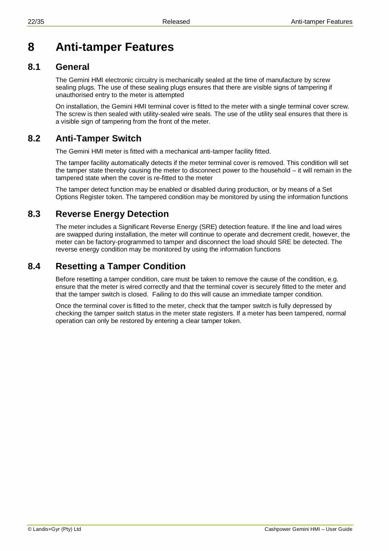
11 Meter Operation (Energy Limiting Mode) The Energy Limiting Mode of operation allows utilities to distribute a fixed amount of energy to customers over a period of time (typically on a monthly basis). It encourages the rational use of energy without severely inconveniencing customers.
11.1 Daily Allocation of Energy (DAE)
This is the amount of energy that a utility will allocate to a customer over a 24-hour period. The value may be changed at any stage by entering a suitable set DAE token.
A „daily‟ value was chosen to prevent confusion when accounting for months having differing numbers of days. Reference to „months‟ elsewhere in this document assumes a 30-day period.
11.2 Operation
Assume that a monthly energy allowance of 150kWh has been allocated to a customer. The Gemini HMI meter allocates this energy in regular, equal portions, over a thirty-day period i.e. by incrementing the kWh credit level with a value of 0.000870kWh every 15 seconds.
Assuming that the customer draws no power at all, the credit level will continue to increase. However, as soon as energy starts to be used, the credit level is proportionately decremented. If the rate at which energy is being used is less than the rate at which it is being incremented, the credit level will slowly continue to increase. If the rate at which energy is being used is greater than the rate at which it is being incremented, the credit level will slowly decrease. It is in the customer‟s interest to ensure that electricity is not wasted and that unnecessary appliances are turned off. By conserving energy, it will be possible to use it at a high rate for periods when required.
In the event of the customer exceeding the allocated allowance (credit level reduced to zero), the load is disconnected. However, the next allocation of credit will be available within a very short period of time (15 seconds) and the supply of electricity to the customer quickly restored. Providing the customer takes immediate steps to disconnect unnecessary appliances, it will be possible to have at least basic services available e.g. lighting. With a 150kWh monthly allocation of energy, it will be possible to maintain a continuous load of 200W whilst still maintaining a positive credit balance.
Figure 12: Graphical representation of Energy Limiting Mode of operation
Timing for the dispensing of the DAE is synchronised to the mains supply frequency. During a power failure the DAE does not continue to increment.
Accumulated
Energy
Accumulated Energy Less
Energy Used by Customer
Energy Used
by Customer
A: Customer starts using energy
B: Customer depletes accumulated
energy and load is disconnected
C: Customer starts using energy again
after load is reconnected
A : Consumer starts using energy.B : Consumer depletes accumulated energy and is disconnected.C : Consumer starts using energy again after reconnection.
0
500
1000
1500
2000
2500
3000
00:0
0
02:0
0
04:0
0
06:0
0
08:0
0
10:0
0
12:0
0
14:0
0
16:0
0
18:0
0
20:0
0
22:0
0
Time in hours
En
erg
y i
n k
W/
h B
CA

26/35 Released Meter Operation (Energy Limiting Mode)
© Landis+Gyr (Pty) Ltd Cashpower Gemini HMI – User Guide
When operating in the energy limiting mode, the meter functions as follows:
The default display shows the amount of accumulated energy currently available.
Because the accumulation of energy takes place at 15-second intervals, the amount incremented each time is very small e.g. 0.000870kWh.
With a normal meter display resolution of 0.1kWh, it will be some time before there is a significant change that actually results in the displayed digits changing. The 15-second changes can be viewed in real time with a resolution of 0.000001kWh via information register 063 – refer to section 13.31).
NB. When in information mode, the scrolling credit wedge is not displayed.
All other display icons work as per the prepayment mode of operation.(refer to section 9).
The load switch will remain in the closed position unless the meter is tampered, decommissioned, in a power limit lockout state or if the DAE has been exceeded.
If the DAE is exceeded, the load switch will operate in exactly the same way as it does when the meter is in power limiting mode. Also note that during the periods that the load is disconnected (for either power limiting or DAE expired), the DAE continues to increment in the background.
11.3 Alarms
The unique functionality of the energy limiting mode of operation requires a variation in the handling of the low credit level alarm thresholds. Because credit levels are automatically incremented, it is possible for the meter to move in and out of the alarm threshold without user interaction.
Another variation is the functioning of set credit level settings. In the energy limiting mode of operation they are not treated as absolute values but interpreted as a percentage of the DAE. This in order to prevent the resetting of alarm levels if and when the DAE values are adjusted. This setting is fixed at the time of manufacture but can be changed via an engineering token at any stage.
The alarm functionality is implemented as follows:
A level of hysteresis is applied to the alarm settings such that it is activated at half of the low credit level setting but only deactivates once it passes back up through the low credit level setting. When in the alarm state, the buzzer sounds and the alert LED is flashed.
The audible alarm may be silenced by pressing any key on the keypad (the alarm LED will continue to flash). It will remain silenced until such time as the credit level has passed back through the low credit level. At this point the alarm LED turns off and, if the remaining credit level is again decremented to below half of the low credit level, the above alarm sequence will again be activated.
If the customer does not press a key on the keypad to silence the alarm as described above, the buzzer will continue to sound and the alert LED flashed while the credit level is
Meter display format in energy limiting mode with credit decreasing
Scrolling direction Scrolling direction
Meter display format in energy limiting mode with credit increasing

Meter Operation (Energy Limiting Mode) Released 27/35
Cashpower Gemini HMI – User Guide © Landis+Gyr (Pty) Ltd
decrementing. If the credit level starts to increment, the buzzer will stop sounding but the alarm LED continues to flash. This behaviour will persist while the remaining credit level is below the low credit level.
NB: The audible alarm functionality described above pertains specifically to the customer interface unit. Other features that allow the function to be disabled or enabled as required are described in section 12.2.
When toggling from energy limiting mode to any of the other modes, normal operation as defined for those modes commences as per the state of the various meter registers e.g. if toggled to the prepayment metering mode and there is no credit in the credit register, the load switch will open.

28/35 Released Customer Interface Unit - Specific Functions
© Landis+Gyr (Pty) Ltd Cashpower Gemini HMI – User Guide
12 Customer Interface Unit - Specific Functions
12.1 General
The Customer Interface Unit (CIU) is effectively a remote extension of the meter‟s Human Machine Interface. It does, however, implement some local functions independently:
12.2 Audible Low-Credit Alarm
This function is provided to give consumers the option of having a timeous audible warning that credit is low and disconnection of the electricity supply could occur soon.
If needed (during normal operation of the customer interface unit), the above default settings can be changed by pressing and holding the „0‟ key on the keypad for 5 seconds. At the end of this period the buzzer beeps once (alarm disabled) or twice (alarm enabled). The mode can be toggled any number of times.
If the default setting of the alarm is changed via the keypad, it will revert to the default status every time power is removed from the customer interface unit.
12.3 Other Audible Tones
The customer interface unit generates a variety of tones in response to token entries e.g. there are two distinctly different tones to indicate Transfer Number Accept or Transfer Number Reject sequences.

Information Functions Released 29/35
Cashpower Gemini HMI – User Guide © Landis+Gyr (Pty) Ltd
13 Information Functions Pressing the information key toggles the meter into information mode (the information icon on the LCD
turns on and all digits display ). The contents of various registers can now be viewed by entering the appropriate, 3-digit register code.
Once in information mode, toggling between different registers may be done on an on-going basis by entering the appropriate 3-digit code i.e. the information key does not have to be pressed again.
Information mode may be exited by pressing the information key or, in the absence
of any other key presses, automatically after a period of 1 minute.
Information Register Functions
Info Register Number Function
000 Meter number
001 Instantaneous power
002 Current credit register (0.1kWh resolution)
003 Total units counter (0.1kWh resolution)
004 DAE accumulated credit register (0.001kWh resolution)
006 Current 24 hr. consumption
007 Previous 24 hr consumption
008 Current 30 day consumption
009 Previous 30 day consumption
011 DAE value (0.01kWh resolution)
012 Low credit level
013 High credit level (not applicable in Energy Limiting Mode)
014 Power limit level
024 Extended meter number
025 Scrolling meter number
030 Meter (fixed) state register 1
031 Meter (fixed) state register 0
035 Meter (changeable) option register 0
037 Meter (display) state register 0
048 Software version number
050 Power-fail counter
054 Last token ID in date format
055 Last credit token ID
056 Value of last credit token entered
057 Key revision and key type
058 Tariff index
059 Current credit register (0.001kWh resolution)
060 SGC register
061 Total units counter (0.001kWh resolution)
062 Current credit register (0.000001kWh resolution)
063 DAE accumulated credit register (0.000001kWh resolution)
064 DAE 15-sec portion register (0.000001kWh resolution)
065 Low credit level (0.000001kWh resolution) – Energy Limiting Mode only
066 Latch inhibit timer (1-minute resolution)
30/35 Released Information Functions
© Landis+Gyr (Pty) Ltd Cashpower Gemini HMI – User Guide
13.1 Meter Number (Register 000)
The meter displays the unique identity number personalised at the time of manufacture. It must match the number printed on the meter‟s front panel label. NB: This number excludes the manufacturer code (“07” in the case of Cashpower meters manufactured in South Africa), check-digit (last digit of the serial number label) and leading zeros of the meter number. For example, meter number 07 0286 6860 1 will be displayed as 286 6860.
13.2 Instantaneous Power (Register 001)
The meter displays the instantaneous power being consumed by the connected load. Readings are updated once per second.
13.3 Current Credit Register – 0.1kWh Resolution (Register 002)
This meter displays the remaining credit in the meter. Note that this is the total remaining credit available and includes credit entered via tokens as well as DAE increments.
13.4 Total Units Counter – 0.1kWh Resolution (Register 003)
The meter displays the total kWh consumed since it was put into service.
13.5 DAE Accumulated Credit Register – 0.001kWh Resolution (Register 004)
The meter displays the total credit that has accumulated via the DAE increments since it was put into service.
13.6 Current 24-Hour Consumption (Register 006)
The meter displays the number of hours into the current 24-hour period, followed by the consumption (kWh) during this period. By pressing the backspace key twice in rapid succession, the hour counter and consumption value is reset to zero and a new cycle commences using this as the reference time.
Note: This does not affect the previous 24-hour period statistic or either of the 30-day statistics.
13.7 Previous 24-Hour Consumption (Register 007)
The meter displays the previous 24-hour period consumption (kWh).
13.8 Current 30-Day Consumption (Register 008)
The meter displays the number of days into the current 30-day period, followed by the consumption (kWh) during this period. By pressing the backspace key twice in rapid succession, the day counter and consumption value is reset to zero and a new cycle commences using this as the reference date.
Note: This does not affect the previous 30-day period statistic or either of the 24-hour statistics.
13.9 Previous 30-Day Consumption (Register 009)
The meter displays the previous 30-day period consumption (kWh).
13.10 DAE Value – 0.01kWh Resolution (Register 011)
The meter displays the amount of energy that has been allocated to a customer over a 24-hour period. It is this value that gets broken down into equal portions and then added to the current credit register (refer to section 13.3) at 15-second intervals when the meter is operating in Energy Limiting Mode.

Information Functions Released 31/35
Cashpower Gemini HMI – User Guide © Landis+Gyr (Pty) Ltd
13.11 Low Credit Level (Register 012)
The meter displays the level at which the lower two credit wedges on the LCD come into operation. Note that this function is handled differently when the meter is operating in Energy Management Mode (refer to section 11)
13.12 High Credit Level (Register 013)
The meter displays the level at which the upper two credit wedges on the LCD come into operation. Note that this function is not applicable when the meter is operating in Energy Limiting Mode (refer to section 11).
13.13 Power Limit Level (Register 014)
The meter displays the power level (in either Amps or Watts) at which the load switch will be opened, causing the supply to the customer to be interrupted.
13.14 Extended Meter Number (Register 024)
The „extended meter number‟ displays the „missing‟ three digits of the STS meter number in the format „07- - - - - n‟ where:
07 is the manufacturer code (07 for S. African manufactured Landis+Gyr meters).
n represents the check digit.
13.15 Scrolling Meter Number (Register 025)
The meter displays the entire (11-digit) meter number i.e. the meter number as described in section 13.1 and the extended meter number as described in section 13.14, by scrolling it in from left to right on the LCD.
13.16 Meter (Fixed) State Register 1 (Register 030)
The meter displays the state in which the meter currently is. Note that these values are stored in the meter‟s EEPROM and will be maintained even if the meter is powered down:
Meter (Fixed) State Register 1
Display Function
XXXX XXX1 Load switch „armed‟ for manual re-closure
XXXX XXXX
XXXX XXXX
01 = Prepayment mode
Active metering mode: 10 = Credit metering mode
11 = Energy limiting mode
XXXX 1XXX Significant reverse energy detected
XXX1 XXXX Stop DAE incrementing when load switch forced open
XX1X XXXX Not used
X1XX XXXX Not used
1XXX XXXX Not used

32/35 Released Information Functions
© Landis+Gyr (Pty) Ltd Cashpower Gemini HMI – User Guide
13.17 Meter (Fixed) State Register 0 (Register 031)
The meter displays the state in which the meter currently is. Note that these values are stored in the meter‟s EEPROM and will be maintained even if the meter is powered down:
Meter (Fixed) State Register 0
Display Function
XXXX XXX1 Meter tampered
XXXX XX1X Meter out of credit
XXXX X1XX Meter in 30-second trip mode (power limit exceeded or DAE expired)
XXXX 1XXX Meter not initialised (default key)
XXX1 XXXX Meter decommissioned
XX1X XXXX DAE expired
X1XX XXXX Load switch forced open
1XXX XXXX Meter in 30-minute lockout mode (power limit exceeded or DAE expired)
On start-up, the 30-second and 30-minute trip/lockout modes are reset i.e. if either of them had been active at the time of powering the meter down, they do not resume from that state when starting up again.
13.18 Meter (Changeable) Option Register 0 (Register 035)
The meter displays the functions personalised at the time of manufacture. These functions can be subsequently changed via a token:
Meter (Changeable) Option Register 0
Display Function (bracketed values apply for bit set to 1)
XXXX XXX1 Display credit register (display total register) on meter as default display
XXXX XX1X Automatic (non-automatic) load switch closing after power limit trip
XXXX X1XX Amps (Watts) power limit display
XXXX 1XXX Do not disconnect / (Disconnect) load switch on power fail
XXX1 XXXX Don‟t tamper (do tamper) on significant reverse energy
XX1X XXXX Tamper detect sensing switch disabled (enabled)
X1XX XXXX Not used
1XXX XXXX Not used

Information Functions Released 33/35
Cashpower Gemini HMI – User Guide © Landis+Gyr (Pty) Ltd
13.19 Meter (Display) State Register 0 (Register 037)
The meter displays various states that are determined each time the meter starts up or that occur during normal operation. They are not stored in EEPROM:
Meter (Display) State Register 0
Display Function (bracketed values apply for bit set to 1)
XXXX XXX1 Not used
XXXX XX1X 50 (60) Hz mains frequency detected
XXXX X1XX Not used
XXXX 1XXX No EEPROM (EEPROM) error detected
XXX1 XXXX Tamper detect sensing switch state closed / (open)
XX1X XXXX Not used
X1XX XXXX Not used
1XXX XXXX Meter out of / (in) creep lock
13.20 Software Version Number (Register 048)
The meter displays the software version number masked into the microprocessor.
13.21 Power-Fail Counter (Register 050)
The meter displays the number of power failures that have occurred to date. This register is cleared with the entry of a tamper reset token – refer to section 7.3.4.
13.22 Last Token ID in Date/Time Format (Register 054)
The meter displays the date and time of issue of the last Credit Transfer Number entered. Note that the display toggles continuously between displaying the date and time.
13.23 Identifier of Last Token Entered (Register 055)
The token identifier is displayed (0 – 16777215) i.e. number of minutes elapsed since 01:01:1993.
13.24 Value of Last Token Entered (Register 056)
The meter displays the value (kWh) of the last Credit Transfer Number entered.
13.25 Key Revision and Key Type (Register 057)
Refer to the STS specification
13.26 Tariff Index (Register 058)
Refer to the STS specification
13.27 Current Credit Register – 0.001kWh Resolution (Register 059)
The meter displays the value of the credit register with a resolution of 0.001kWh. The most significant digit of the display (if in use) will be “pushed” off the display in this mode.
13.28 Supply Group Code (SGC) Register (Register 060)
This register will contain the initial SGC value, personalised at the time of manufacture. Once a successful meter key-change has been performed, the information is no longer valid and is, therefore, cleared. This option gives a quick indication of whether a key-change has been performed on the meter.

34/35 Released Information Functions
© Landis+Gyr (Pty) Ltd Cashpower Gemini HMI – User Guide
13.29 Total Units Counter – 0.001kWh Resolution (Register 061)
The meter displays the value of the total units register with a resolution of 0.001kWh. The most significant digit of the display (if in use) will be “pushed” off the display in this mode.
13.30 Current Credit Register – 0.000001kWh Resolution (Register 062)
The meter displays the value of the current credit register with a resolution of 0.000001kWh. The most significant digits of the display (if in use) will be “pushed” off the display in this mode. This is a very high resolution display that allows one to view both the incrementing of the credit register by the DAE at 15-second intervals as well as it decrementing due to the energy consumed by any connected load.
13.31 DAE Accumulated Credit Register – 0.000001kWh Resolution (Register 063)
The meter displays the value of the total credit entered into the meter via the DAE method with a resolution of 0.000001kWh. The most significant digits of the display (if in use) will be “pushed” off the display in this mode. This is a very high resolution display that allows one to view the incrementing of the credit register by the DAE at 15-second intervals.
13.32 DAE 15-Second Portion Register – 0.000001kWh Resolution (Register 064)
The meter displays the energy value that gets added to the current credit register every 15 seconds with a resolution of 0.000001kWh. The most significant digits of the display (if in use) will be “pushed” off the display in this mode.
13.33 Low Credit Level – 0.000001kWh Resolution (Register 065)
The meter displays the level at which the lower two credit wedges on the LCD come into operation with a resolution of 0.000001kWh. Note that this function is handled differently when the meter is operating in Energy Limiting Mode – refer to section 11.
13.34 Latch Inhibit Timer – 1-Minute Resolution (Register 066)
When the load switch has opened due to either a power limiting event or expiry of DAE and is in a 30-minute lockout state, the register displays the time remaining before the load switch will close again.

Error Codes Released 35/35
Cashpower Gemini HMI – User Guide © Landis+Gyr (Pty) Ltd
Copyright © 2005-2011 Landis+Gyr. All rights reserved. Subject to change without notice.
Landis+Gyr (Pty) Ltd
2 Slate Avenue, N1 Business Park
Old Johannesburg Road, Kosmosdal Ext. 7
Gauteng, South Africa
Tel: +12 645 3100
www.landisgyr.com/za
14 Error Codes
14.1 Meter
In the unlikely event of a catastrophic malfunction in the meter (meter), the supply to the consumer will be disconnected and a two-digit error code in the form ---XX--- displayed.
14.2 Customer Interface Unit
In the event of a communications failure with the customer interface unit (other than a broken wire, in which case the customer interface unit would not be powered) a two-digit error code in the form ---05--- will be displayed.