
Case Study of an ASIL D Torque Vectored Electric...
22
Presented by David Blackburn 23/09/2013 Revision 1 Case Study of an ASIL D Torque Vectored Electric Power Train Aligned to ISO26262
Transcript of Case Study of an ASIL D Torque Vectored Electric...
Presented by David Blackburn
23/09/2013
Revision 1
Case Study of an ASIL D Torque Vectored Electric Power Train
Aligned to ISO26262
2 © Zytek Group
Introduction
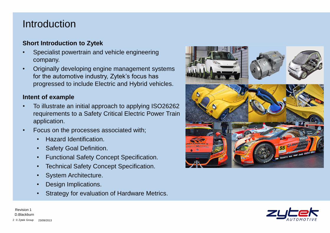
Short Introduction to Zytek
• Specialist powertrain and vehicle engineering
company.
• Originally developing engine management systems
for the automotive industry, Zytek’s focus has
progressed to include Electric and Hybrid vehicles.
23/09/2013
D.Blackburn
Revision 1
Intent of example
• To illustrate an initial approach to applying ISO26262
requirements to a Safety Critical Electric Power Train
application.
• Focus on the processes associated with;
• Hazard Identification.
• Safety Goal Definition.
• Functional Safety Concept Specification.
• Technical Safety Concept Specification.
• System Architecture.
• Design Implications.
• Strategy for evaluation of Hardware Metrics.
3 © Zytek Group
Vehicle Application
Rear wheeled drive lightweight sports car.
• High Level Architecture
• x2 Independent Electric Machines and Power Electronics (PE’s).
• Single communications bus between the PE’s and the rest of the vehicle.
• Single stage gearing
• No mechanical differential.
• Directly coupled to the drive wheel with no mechanical disconnect / master clutch.
• Performance
• Power: 300 kW (Approx. 400 hp).
• Torque: 850 Nm @ Machine Shaft (combined): 5100 Nm @ Wheels.
• Performance: 0 – 100 km/h approx. 4 seconds.
• Torque Vectoring available at all speeds.
23/09/2013
D.Blackburn
Revision 1
4 © Zytek Group
Safety Targets
Vehicle Level Hazard
• Unbalanced lateral torque across the vehicle, leading to the loss of control.
Hazard Analysis
• Considering the maximum differential wheel torque error possible (5100 Nm) under different road
surface conditions yields different Fault Tolerant Time Intervals (FTTI).
• Dry surface (high coefficient of friction)
• 5100 Nm Torque Error.
• FTTI = 100 ms.
• Wet surface (medium coefficient of friction)
• 5100 Nm Torque Error.
• FTTI = 60 ms.
• Icy surface (low coefficient of friction)
• 5100 Nm Torque Error.
• FTTI = 40 ms.
• The Probability of Exposure to the different road surface conditions then links these Fault Tolerant
Time Intervals to ASIL targets.
23/09/2013
D.Blackburn
Revision 1
5 © Zytek Group
ASIL Determination
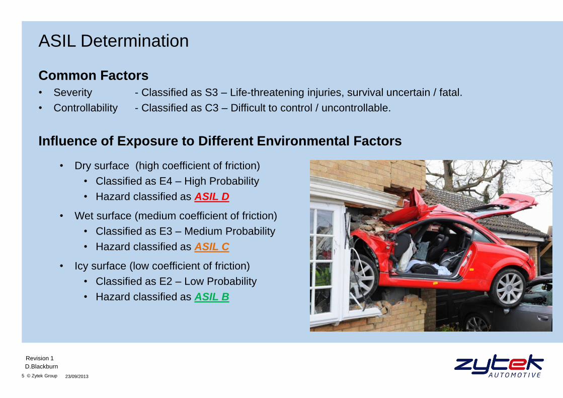
Common Factors
• Severity - Classified as S3 – Life-threatening injuries, survival uncertain / fatal.
• Controllability - Classified as C3 – Difficult to control / uncontrollable.
Influence of Exposure to Different Environmental Factors
• Dry surface (high coefficient of friction)
• Classified as E4 – High Probability
• Hazard classified as ASIL D
• Wet surface (medium coefficient of friction)
• Classified as E3 – Medium Probability
• Hazard classified as ASIL C
• Icy surface (low coefficient of friction)
• Classified as E2 – Low Probability
• Hazard classified as ASIL B
23/09/2013
D.Blackburn
Revision 1

6 © Zytek Group
Safety Targets
ASIL Table – ISO26262 Part 3
23/09/2013
D.Blackburn
Revision 1
Severity Class Probability Class Controllability Class
C1 C2 C3
S1
E1 QM QM QM
E2 QM QM QM
E3 QM QM A
E4 QM A B
S2
E1 QM QM QM
E2 QM QM A
E3 QM A B
E4 A B C
S3
E1 QM QM A
E2 QM A B
E3 A B C
E4 B C D
7 © Zytek Group
Safety Goals (SG)
(Definition: Highest level safety requirement, hence a ‘Black Box’ vehicle requirement)
List of Derived Safety Goals
SG1: Differential wheel torque of 5100 Nm, persistent for 100ms (510 Nms) shall be prevented.
Integrity: ASIL D
SG2: Differential wheel torque of 5100 Nm, persistent for 60ms (306 Nms) shall be prevented.
Integrity: ASIL C
SG3: Differential wheel torque of 5100 Nm, persistent for 40ms (204 Nms) shall be prevented.
Integrity: ASIL B
Failure of a number of different subsystems within the vehicle architecture have the potential to violate
these Safety Goals. The supplied drivetrain forms only part of this.
For purposes of this example, the influence of other failures beyond the Drivetrain are not considered.
23/09/2013
D.Blackburn
Revision 1
8 © Zytek Group
System Level FMEA Functions and Corresponding Failure Modes
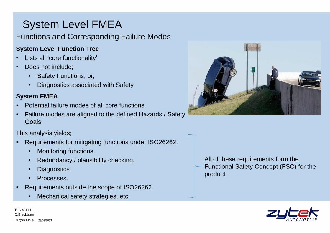
System Level Function Tree
• Lists all ‘core functionality’.
• Does not include;
• Safety Functions, or,
• Diagnostics associated with Safety.
System FMEA
• Potential failure modes of all core functions.
• Failure modes are aligned to the defined Hazards / Safety
Goals.
This analysis yields;
• Requirements for mitigating functions under ISO26262.
• Monitoring functions.
• Redundancy / plausibility checking.
• Diagnostics.
• Processes.
• Requirements outside the scope of ISO26262
• Mechanical safety strategies, etc.
23/09/2013
D.Blackburn
Revision 1
All of these requirements form the
Functional Safety Concept (FSC) for the
product.
9 © Zytek Group
Functional Safety Concept / Requirements
(Definition: Implementation independent safety behavior, allocated to architectural elements. Therefore
a collection of ‘Black Box’ sub-system requirements)
Functional Safety Requirements (FSR) Addressing SG1
FSR 1
1a. Each inverter shall ensure that the integral of torque error between the Left and Right drive
wheels remains below 510Nm seconds.
Integrity: ASIL D
1b. The FTTI shall be < 510Nms ( i.e. 100ms for 5100Nm, 200ms for 2550Nm, etc).
Integrity: ASIL D
1c. Safe state definition: All applied torque at both wheels shall be reduced to within the defined
Safe Residual Braking Torque limits.
Integrity: ASIL D
The Functional Safety Requirements addressing SG2 and SG3 are similar to those for SG1, with
different torque integral thresholds, FTTI’s and integrity requirements.
23/09/2013
D.Blackburn
Revision 1
10 © Zytek Group
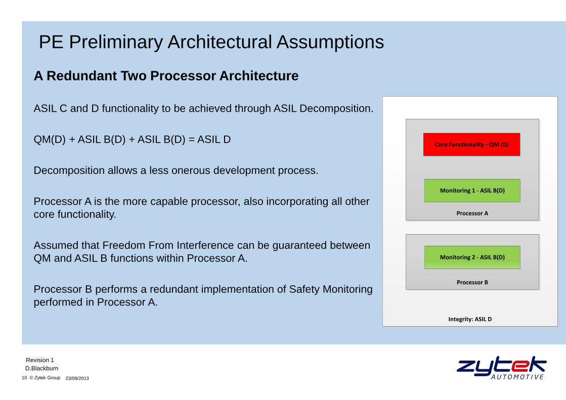
PE Preliminary Architectural Assumptions
A Redundant Two Processor Architecture
ASIL C and D functionality to be achieved through ASIL Decomposition.
QM(D) + ASIL B(D) + ASIL B(D) = ASIL D
Decomposition allows a less onerous development process.
Processor A is the more capable processor, also incorporating all other
core functionality.
Assumed that Freedom From Interference can be guaranteed between
QM and ASIL B functions within Processor A.
Processor B performs a redundant implementation of Safety Monitoring
performed in Processor A.
23/09/2013
D.Blackburn
Revision 1
Integrity: ASIL D
Processor B
Processor A
Core Functionality - QM (D)
Monitoring 1 - ASIL B(D)
Monitoring 2 - ASIL B(D)
11 © Zytek Group
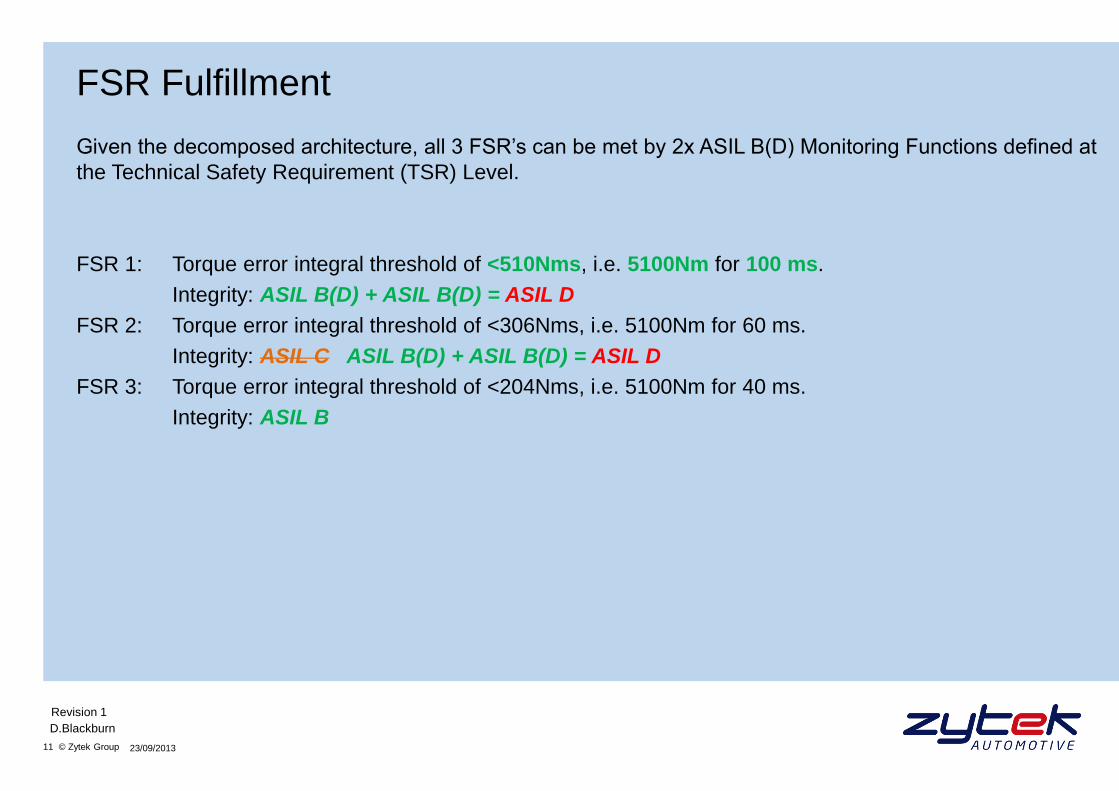
FSR Fulfillment
Given the decomposed architecture, all 3 FSR’s can be met by 2x ASIL B(D) Monitoring Functions defined at
the Technical Safety Requirement (TSR) Level.
FSR 1: Torque error integral threshold of <510Nms, i.e. 5100Nm for 100 ms.
Integrity: ASIL B(D) + ASIL B(D) = ASIL D
FSR 2: Torque error integral threshold of <306Nms, i.e. 5100Nm for 60 ms.
Integrity: ASIL C ASIL B(D) + ASIL B(D) = ASIL D
FSR 3: Torque error integral threshold of <204Nms, i.e. 5100Nm for 40 ms.
Integrity: ASIL B
23/09/2013
D.Blackburn
Revision 1
12 © Zytek Group
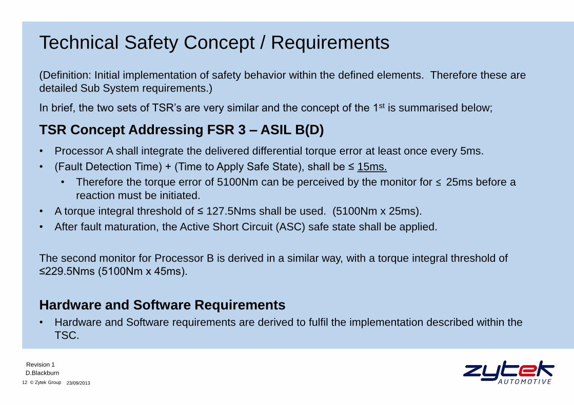
Technical Safety Concept / Requirements
(Definition: Initial implementation of safety behavior within the defined elements. Therefore these are
detailed Sub System requirements.)
In brief, the two sets of TSR’s are very similar and the concept of the 1st is summarised below;
TSR Concept Addressing FSR 3 – ASIL B(D)
• Processor A shall integrate the delivered differential torque error at least once every 5ms.
• (Fault Detection Time) + (Time to Apply Safe State), shall be ≤ 15ms.
• Therefore the torque error of 5100Nm can be perceived by the monitor for ≤ 25ms before a
reaction must be initiated.
• A torque integral threshold of ≤ 127.5Nms shall be used. (5100Nm x 25ms).
• After fault maturation, the Active Short Circuit (ASC) safe state shall be applied.
The second monitor for Processor B is derived in a similar way, with a torque integral threshold of
≤229.5Nms (5100Nm x 45ms).
Hardware and Software Requirements
• Hardware and Software requirements are derived to fulfil the implementation described within the
TSC.
23/09/2013
D.Blackburn
Revision 1
13 © Zytek Group
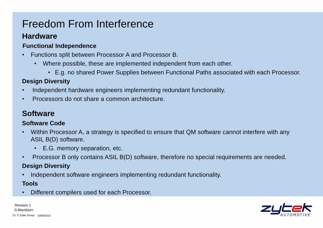
Freedom From Interference
Hardware
Functional Independence
• Functions split between Processor A and Processor B.
• Where possible, these are implemented independent from each other.
• E.g. no shared Power Supplies between Functional Paths associated with each Processor.
Design Diversity
• Independent hardware engineers implementing redundant functionality.
• Processors do not share a common architecture.
Software
Software Code
• Within Processor A, a strategy is specified to ensure that QM software cannot interfere with any
ASIL B(D) software.
• E.G. memory separation, etc.
• Processor B only contains ASIL B(D) software, therefore no special requirements are needed.
Design Diversity
• Independent software engineers implementing redundant functionality.
Tools
• Different compilers used for each Processor.
23/09/2013
D.Blackburn
Revision 1
14 © Zytek Group
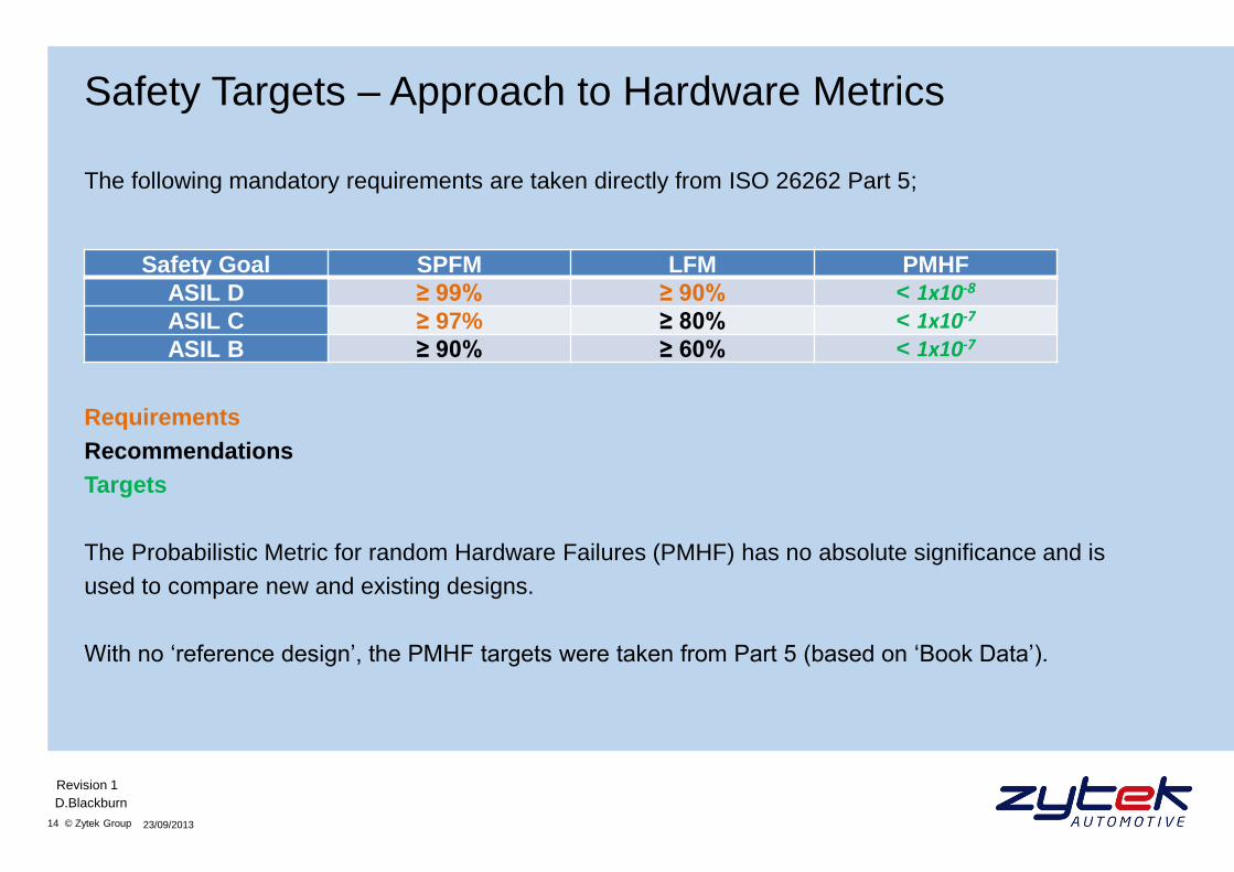
Safety Targets – Approach to Hardware Metrics
The following mandatory requirements are taken directly from ISO 26262 Part 5;
Requirements
Recommendations
Targets
The Probabilistic Metric for random Hardware Failures (PMHF) has no absolute significance and is
used to compare new and existing designs.
With no ‘reference design’, the PMHF targets were taken from Part 5 (based on ‘Book Data’).
23/09/2013
D.Blackburn
Revision 1
Safety Goal SPFM LFM PMHF
ASIL D ≥ 99% ≥ 90% < 1x10⁻⁸ ASIL C ≥ 97% ≥ 80% < 1x10⁻⁷ ASIL B ≥ 90% ≥ 60% < 1x10⁻⁷
15 © Zytek Group
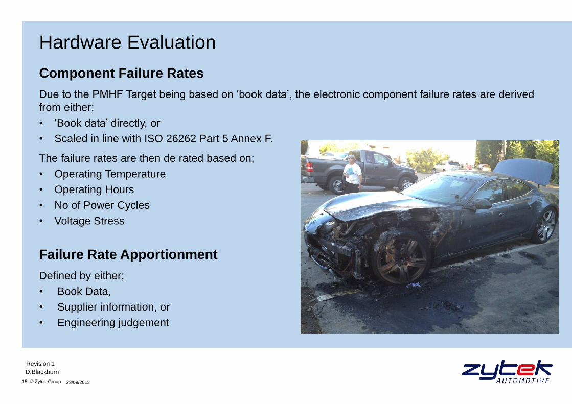
Hardware Evaluation
Component Failure Rates
Due to the PMHF Target being based on ‘book data’, the electronic component failure rates are derived
from either;
• ‘Book data’ directly, or
• Scaled in line with ISO 26262 Part 5 Annex F.
The failure rates are then de rated based on;
• Operating Temperature
• Operating Hours
• No of Power Cycles
• Voltage Stress
Failure Rate Apportionment
Defined by either;
• Book Data,
• Supplier information, or
• Engineering judgement
23/09/2013
D.Blackburn
Revision 1
16 © Zytek Group
Hardware Path FMEA
Each Functional Path was then split into the following elements;
• Input
• Logic
• Output
A component level FMEA was performed for each of the Hardware Path Elements.
This yields a list of failure modes and associated failure rates for each functional element.
If the function is split correctly and the failure modes defined accordingly, then a proportion of the FMEA
analysis can be modularised and reused in new designs.
In order to do this;
• Clear identification of element boundaries.
• Failure modes to be focused on the boundary of the Element and not at the ‘higher level’ intent.
• Schematics to be designed with modular elements in mind.
23/09/2013
D.Blackburn
Revision 1
17 © Zytek Group
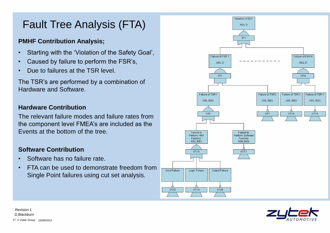
Fault Tree Analysis (FTA)
PMHF Contribution Analysis;
• Starting with the ‘Violation of the Safety Goal’,
• Caused by failure to perform the FSR’s,
• Due to failures at the TSR level.
The TSR’s are performed by a combination of
Hardware and Software.
Hardware Contribution
The relevant failure modes and failure rates from
the component level FMEA’s are included as the
Events at the bottom of the tree.
Software Contribution
• Software has no failure rate.
• FTA can be used to demonstrate freedom from
Single Point failures using cut set analysis.
23/09/2013
D.Blackburn
Revision 1
18 © Zytek Group
Diagnostic Coverage (DC)
There is inherent redundancy with the decomposed implementation of the ASIL D functionality.
For the purposes of DC analysis;
• The Primary Safety Functions are implemented by Processor A, and
• The Secondary Safety Functions are implemented by Processor B.
Additional diagnostics and plausibility strategies are defined at the TSR level.
These are architected into the FTA to propagate the correct failure rates.
Single Point Failures
• Associated with failures of Primary Safety Functions.
• Safety Mechanisms (SM’s) to mitigate Single Point failures are reliant on;
• Diagnostic functionality within the Primary Safety Functions.
Latent Faults / Dual Point Faults
• Safety Mechanisms (SM’s) to mitigate Latent / Dual Point failures are reliant on;
• The (redundant) Secondary Functions.
23/09/2013
D.Blackburn
Revision 1
19 © Zytek Group
Calculation of H/W Metrics
PMHF – Targets not achieved
• Once all DC strategies are represented in the Fault Trees, the FTA tool calculates the λd for the SG.
• Common hardware failures are revealed in the Cut Set Analysis, also performed by the FTA tool.
SPFM – Achieved >99%
• Calculated using the SM’s detailed for Single Point Faults.
• Uses DC derived from either;
• Part 5 Annex D, or,
• Engineering judgement.
LFM – Achieved >95%
• Calculated using the SM’s detailed for Latent / Dual Point Faults.
• DC derived in the same way as SPFM DC.
Part 5 allows for the SPFM and LFM calculations to be performed by combining all SG’s.
• By taking the metric targets of the highest ASIL under consideration, hence ASIL D targets.
23/09/2013
D.Blackburn
Revision 1
20 © Zytek Group
Issues During Development
• Short project timescales;
• ISO 26262 design process performed out of sequence / retrospectively.
• Increased risk of not fulfilling the Safety intent.
• Undefined Staged Vehicle Safety Releases
• ASIL B required for restricted ‘On Highway’ development.
• ASIL D required for development completion.
• Leading to additional revalidation effort.
23/09/2013
D.Blackburn
Revision 1
• The diagnostic strategy that defines how failures are mitigated
was not clear at the H/W design level, leading to;
• Diagnostic coverage being calculated retrospectively.
• Independence between SM’s compromised.
• FMEA modularisation process was developed during the
project, leading to;
• Schematic rework.
• Failure modes difficult to interpret.
• A very pessimistic analysis.
21 © Zytek Group
Lessons Learned
Key Elements That Require Early Adoption
• Complete Safety Plan with;
• Realistic Timescales to perform requirements capture in sequence.
• Development Safety Release milestones defined.
• Fault Tree Analysis must be performed to a TSR level very early on.
• Clear traceability between the violation of the SG and the failure of functions within the TSC.
• Highlights weaknesses in the Diagnostic Coverage strategy.
• Early indication of problem areas with excessive failure rates.
• Requirements for independence between functions more clear.
• Specify freedom from interference requirements for PCB layout.
• Avoid shared use of ‘multi-packaged’ devices.
Hardware Design Guidance
• Modular Schematic representation.
• FMEA analysis framework.
Power On Strategy
• Recommend that the PE does not power up during charging.
23/09/2013
D.Blackburn
Revision 1
22 © Zytek Group
Questions?
Contact Information
Contact: David Blackburn
Role: Principal Engineer – Product Safety
Email: [email protected]
Tel: +44(0)1543 412175
Website: zytekautomotive.co.uk
23/09/2013
D.Blackburn
Revision 1


![Vectored Thrust Flying Wing - Hobbicomanuals.hobbico.com/flz/flza3612-14-manual.pdf · Vectored Thrust Flying Wing ... Weight: 29.6 – 31.3 oz [840 – 885 g] Wing Loading: 10.4](https://static.fdocuments.us/doc/165x107/5af1af897f8b9a8b4c8f147a/vectored-thrust-flying-wing-thrust-flying-wing-weight-296-313-oz-840.jpg)


