Case Study: Installation of Canal Control Structures on ...
13
Presented at the July 9-12, 2002 USCID conference on Benchmarking Irrigation System Performance Using Water Measurement and Water Balances. San Luis Obispo, CA. http://www.itrc.org/papers/installation/installation.pdf ITRC Paper No. P02-005 CASE STUDY: INSTALLATION OF CANAL CONTROL STRUCTURES ON THE GOVERNMENT HIGHLINE CANAL Ram Dhan Khalsa 1 , Stuart Styles 2 , Charles Burt 3 , Bob Norman 4 ABSTRACT The Government Highline Canal Modernization Study was completed in April 2000 to evaluate options for reducing the flow rate requirement of the Government Highline Canal in order to increase the water supply in the “15-Mile Reach” of the Colorado River, thereby helping sustain habitat for fish species identified as endangered. The intent was to develop a design for which Colorado River diversions could be better matched to on-farm demands. It was determined that canal modernization, in the form of automated canal structures, in-system storage, and new operational procedures could significantly reduce operational spill. A systematic evaluation of the existing canal system and operations identified a potential savings of 28,500 acre-feet of water that could remain in the river or be returned to the river upstream of the 15-Mile Reach. This paper is an update to one done in 1999 for USCID about the Modernization Study. This paper will focus on the lessons learned from the actual implementation of the recommended structural and operational improvements, in particular the construction of the main components of this project including canal control structures. INTRODUCTION The Government Highline Canal is part of the federal Grand Valley Project in the Colorado River Basin in west-central Colorado, USA. The project is located at the confluence of the Colorado and Gunnison Rivers at Grand Junction, Colorado (refer to Figure 1). The elevation of Grand Junction is about 4600 feet (above sea level). The United States Bureau of Reclamation (USBR) built the Government 1 Design Engineer, Western Colorado Area Office, Northern Division, United States Bureau of Reclamation (USBR), Grand Junction, Colorado 81506. 2 Director, Irrigation Training and Research Center (ITRC), California Polytechnic State University (Cal Poly), San Luis Obispo, California 93407. 3 Professor and Chairman, ITRC, Cal Poly, San Luis Obispo, California 93407. 4 Planning Engineer, Western Colorado Area Office, Northern Division, USBR, Grand Junction, Colorado 81506. Irrigation Training and Research Center (ITRC) – www.itrc.org
Transcript of Case Study: Installation of Canal Control Structures on ...

Presented at the July 9-12, 2002 USCID conference on Benchmarking Irrigation System Performance Using Water Measurement and Water Balances. San Luis Obispo, CA.
http://www.itrc.org/papers/installation/installation.pdf ITRC Paper No. P02-005
CASE STUDY: INSTALLATION OF CANAL CONTROL STRUCTURES ON THE GOVERNMENT HIGHLINE CANAL
Ram Dhan Khalsa1, Stuart Styles2, Charles Burt3, Bob Norman4
ABSTRACT
The Government Highline Canal Modernization Study was completed in April 2000 to evaluate options for reducing the flow rate requirement of the Government Highline Canal in order to increase the water supply in the “15-Mile Reach” of the Colorado River, thereby helping sustain habitat for fish species identified as endangered. The intent was to develop a design for which Colorado River diversions could be better matched to on-farm demands. It was determined that canal modernization, in the form of automated canal structures, in-system storage, and new operational procedures could significantly reduce operational spill. A systematic evaluation of the existing canal system and operations identified a potential savings of 28,500 acre-feet of water that could remain in the river or be returned to the river upstream of the 15-Mile Reach.
This paper is an update to one done in 1999 for USCID about the Modernization Study. This paper will focus on the lessons learned from the actual implementation of the recommended structural and operational improvements, in particular the construction of the main components of this project including canal control structures.
INTRODUCTION
The Government Highline Canal is part of the federal Grand Valley Project in the Colorado River Basin in west-central Colorado, USA. The project is located at the confluence of the Colorado and Gunnison Rivers at Grand Junction, Colorado (refer to Figure 1). The elevation of Grand Junction is about 4600 feet (above sea level). The United States Bureau of Reclamation (USBR) built the Government
1 Design Engineer, Western Colorado Area Office, Northern Division, United States Bureau of Reclamation (USBR), Grand Junction, Colorado 81506. 2 Director, Irrigation Training and Research Center (ITRC), California Polytechnic State University (Cal Poly), San Luis Obispo, California 93407. 3 Professor and Chairman, ITRC, Cal Poly, San Luis Obispo, California 93407. 4 Planning Engineer, Western Colorado Area Office, Northern Division, USBR, Grand Junction, Colorado 81506.
Irrigation Training and Research Center (ITRC) – www.itrc.org

Presented at the July 9-12, 2002 USCID conference on Benchmarking Irrigation System Performance Using Water Measurement and Water Balances. San Luis Obispo, CA.
http://www.itrc.org/papers/installation/installation.pdf ITRC Paper No. P02-005
Highline Canal in the 1910s in cooperation with the Grand Valley Water Users Association (GVWUA). The Government Highline Canal receives water from the Grand Valley Project diversion dam. The canal travels in a mostly westerly direction for 55 miles (88.5 km) to the Badger Wash Check. The diversion dam is located about 8 miles (12.9 km) northeast of Palisade. The main canal has a diversion capacity of about 1,675 cfs (47.4 cms), about half of which goes to the Orchard Mesa Power Canal (OMPC) and half continues to GVWUA and other water users. The irrigated service area of the GVWUA is about 23,300 acres (9,400 ha). Project facilities are owned by the USBR; the facilities are maintained and operated by the GVWUA.
In 1987 the United States Fish and Wildlife Service (USFWS) developed the Recovery Implementation Program for the Endangered Fish Species in the Upper Colorado River Basin (Recovery Program), which identified a 15-Mile Reach of the Colorado River near Grand Junction, Colorado as an area needing additional water supplies during the late summer and fall months (August through November) to maintain habitat conditions for several identified endangered fish species (USBR 1998). The Grand Valley Water Management Project was established to evaluate potential improvements that could be incorporated into the USBR’s Grand Valley Project in order to provide additional flows in the 15-Mile Reach.
As a continuation of the Grand Valley Water Management Project a team of five agencies completed the Government Highline Canal Modernization Study (Modernization Study). The project team included the United States Bureau of Reclamation (USBR) Western Colorado Area Office in Grand Junction, Colorado; the Irrigation Training and Research Center (ITRC), California Polytechnic State University in San Luis Obispo, California; the Grand Valley Water Users Association (GVWUA) in Grand Junction, Colorado; the USBR Technical Services Center (TSC) in Denver, Colorado; and the University of Iowa’s Hydraulic Research Laboratory (IHRL) in Iowa City, Iowa.
A systematic evaluation of the existing Government Highline Canal, including current management practices and operation of project facilities, identified a potential savings of 28,500 acre-feet of water that could remain in the Colorado River or be returned to the river upstream of the 15-Mile Reach. An important aspect of the Modernization Study was the desire to maintain the current high level of water delivery service provided to the GVWUA customers, yet have less spill. The study made specific, pragmatic recommendations for reducing operational spill. The detailed analysis conducted as part of the Modernization Study is summarized in Styles et al. 1999. Funding for the initial modernization study was provided by the USBR. After the potential to reduce diversions by 28,500 acre-feet was identified, the Recovery Program agreed to fund the remainder of the study and the proposed improvements. The cost for the studies and improvements is approximately $7,000,000.
Irrigation Training and Research Center (ITRC) – www.itrc.org

Presented at the July 9-12, 2002 USCID conference on Benchmarking Irrigation System Performance Using Water Measurement and Water Balances. San Luis Obispo, CA.
http://www.itrc.org/papers/installation/installation.pdf ITRC Paper No. P02-005
Diversion DamGunnison River
Government Entrance to Tunnel #3
Highline Canal Entrance to Power CanalPrice Stubb Check
New Bypass Turnout Power Canal
Clifton Check
New Site (near Lewis Wash Siphon)
New Site (Indian Wash Flume)
New Site (near A7)
New Site (near A15)
New Site (near A21.5)
New Site (near A27)
New Site (near A32)
Stewart Wash (Double AMIL Gates)
Big Salt Wash
16 Rd Check
13 Road Check Colorado River
Highline Lake (Camp 7)
Check A49 Highline Lake
East Salt Wash CheckLEGEND
8 Road CheckBadger Wash Completely New Check
Badger Wash Check Modify Existing Check
Existing Check (new electronics)
Figure 1. Government Highline Canal Check Locations
MODERNIZATION PROJECT: CANAL CONTROL STRUCTURES
The goal of the Government Highline Canal modernization project was to maintain the same level of flexibility and reliability of service to the GVWUA customers, yet have less spill. The proposed improvements would allow for more water to flow into the “15-Mile Reach” of the Colorado River. Implementation of the project is expected to cause a 28,500 acre-feet reduction in the operational spill requirements of the GVWUA during the months of August through October. The manager will have better access to information and will be able to make more
Irrigation Training and Research Center (ITRC) – www.itrc.org

Presented at the July 9-12, 2002 USCID conference on Benchmarking Irrigation System Performance Using Water Measurement and Water Balances. San Luis Obispo, CA.
http://www.itrc.org/papers/installation/installation.pdf ITRC Paper No. P02-005
frequent flow rate changes at the canal headworks. In addition, the manager will have new capabilities for flow rate control at Camp 7 and at the new Palisade Pipeline Turnout (described below).
The main features of the modernization project are:
• Seven new check structures (operational in 2001) • New pump station at Highline Lake and the use of Highline Lake as a
buffer reservoir (planned in 2003) • New Palisade Pipeline turnout to the Colorado River upstream of the
15-Mile Reach (operational in 2001) • Implementation of SCADA - Supervisory Control and Data
Acquisition (planned for 2002) • Twenty-one new Remote Terminal Unit (RTU) sites connected by
radio • New central office control facilities • Modification to thirteen existing check structures • Modification to the OMPC turnout
The following sections describe the structural details and operational characteristics of the new and modified canal control structures. The discussion begins at the canal headworks and proceed in a downstream direction.
Government Highline Canal Headworks
The Government Highline Canal headworks structure consists of nine sluice gates. A single motor, located in an adjacent structure, powers a shaft, which can drive all of the gates simultaneously, or as many as are desired. A single stage “Littleman” controller is used to control the flow rate into the canal. The water level in the canal at the Littleman float location approximately 500 ft downstream of the headworks is approximately calibrated to flow rate.
The improvements to the headworks will provide the GVWUA with the capability to monitor and make changes to the canal flow rate remotely from a central office. This will be accomplished with the installation of a new, reliable controller, a water level sensor to replace the float and stilling well for the Littleman, a new RTU to control the gate motor, a gate position sensor, and the incorporation of radio communications. The office computer will display the gate position and the flow rate and operators will have the ability to change set-point from the office or on site.
The modified operation of this site will be similar to the current procedures. Only one gate will be adjusted to fine tune control; the other eight gates are only for gross flow rate control. The flow rate will be measured using an MGD acoustic Doppler flow meter.
Irrigation Training and Research Center (ITRC) – www.itrc.org

Presented at the July 9-12, 2002 USCID conference on Benchmarking Irrigation System Performance Using Water Measurement and Water Balances. San Luis Obispo, CA.
http://www.itrc.org/papers/installation/installation.pdf ITRC Paper No. P02-005
Inlet to Tunnel #3
At this site the canal splits between the Government Highline Canal and the Orchard Mesa Power Canal (OMPC). Diverted water flows through a radial gate, into an inverted siphon, across the Colorado River, and into the OMPC. A radial gate also controls the entrance to the Government Highline Canal. Previously the operation of the two gates was somewhat complex and the canal operators needed a day of adjustments to make a single flow rate change. The radial gate was manually adjusted with a wheel crank to maintain the desired water level in the OMPC.
A new RTU will be added at the Inlet to Tunnel #3 to control the two radial gates. The radial gate controlling the entrance to the Government Highline Canal will be automated with local closed-loop control to automatically maintain the upstream water level using the same RTU as the OMPC gate. The radial gate controlling the entrance to the OMPC siphon will be adjusted by operators at the district office (remote manual control) based on the flow rate into the OMPC. The flow rate will be determined from the water level in the OMPC downstream of the siphon under the Colorado River using a second RTU that communicates via 470 MHz spread spectrum radio to the controlling RTU.
Both gates will be equipped with new electrical gate actuators. The radial gate at the entrance to Tunnel 3 will be moved much more frequently. Therefore, the complete hoist mechanism will be replaced, and the gate hinges will be inspected thoroughly and repaired or replaced as necessary. A requirement for each of the check gates was the that the control of the gate must allow for the gate to be operated in a fully open mode such that the gate is out of the water.
Because of the critical nature of this control point redundant water level sensors were installed in the pool at the inlet to Tunnel #3 and in the OMPC across the river from the Tunnel 3 entrance.
Price-Stubb Check
The Price-Stubb check structure is located at the exit of Tunnel 3. The check structure consists of three stoplog bays to maintain the upstream water level. Current plans are to remove the stop log bays and install a new automated Langeman gate in the check structure. The gate will be locally controlled to maintain a desired upstream water surface elevation. The SCADA system will be set to provide an automatic alarm to the gate operator if the single automated gate position is either almost completely closed or completely open.
Palisade Pipeline Turnout (new facility)
Palisade Pipeline is a key structure of the modernization program - its simplicity and location will reduce the lag time normally associated with flow rate changes
Irrigation Training and Research Center (ITRC) – www.itrc.org
Presented at the July 9-12, 2002 USCID conference on Benchmarking Irrigation System Performance Using Water Measurement and Water Balances. San Luis Obispo, CA.
http://www.itrc.org/papers/installation/installation.pdf ITRC Paper No. P02-005
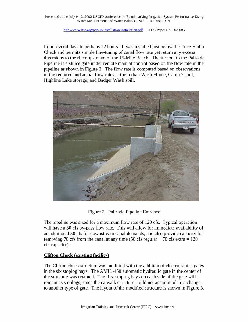
from several days to perhaps 12 hours. It was installed just below the Price-Stubb Check and permits simple fine-tuning of canal flow rate yet return any excess diversions to the river upstream of the 15-Mile Reach. The turnout to the Palisade Pipeline is a sluice gate under remote manual control based on the flow rate in the pipeline as shown in Figure 2. The flow rate is computed based on observations of the required and actual flow rates at the Indian Wash Flume, Camp 7 spill, Highline Lake storage, and Badger Wash spill.
Figure 2. Palisade Pipeline Entrance
The pipeline was sized for a maximum flow rate of 120 cfs. Typical operation will have a 50 cfs by-pass flow rate. This will allow for immediate availability of an additional 50 cfs for downstream canal demands, and also provide capacity for removing 70 cfs from the canal at any time (50 cfs regular + 70 cfs extra = 120 cfs capacity).
Clifton Check (existing facility)
The Clifton check structure was modified with the addition of electric sluice gates in the six stoplog bays. The AMIL-450 automatic hydraulic gate in the center of the structure was retained. The first stoplog bays on each side of the gate will remain as stoplogs, since the catwalk structure could not accommodate a change to another type of gate. The layout of the modified structure is shown in Figure 3.
Irrigation Training and Research Center (ITRC) – www.itrc.org

Presented at the July 9-12, 2002 USCID conference on Benchmarking Irrigation System Performance Using Water Measurement and Water Balances. San Luis Obispo, CA.
http://www.itrc.org/papers/installation/installation.pdf ITRC Paper No. P02-005
A new RTU was installed to monitor: i) position of the AMIL gate for an indication of stoplog maintenance, ii) position of the new sluice gates, iii) upstream water level, and iv) downstream water level in the Lewis Wash Check reach.
AMIL Gate
Figure 3. Clifton Check with new manual sluice gates
Lewis Wash Check and all new check structures
Automatic radial gates with two long crested weirs were the selected option for the new structures on the Government Highline Canal. The completed installation of a typical installation is shown in Figure 4. Figure 5 shows the general layout of the check structure. This provides the most flexibility for the GVWUA. The design included automatic electric radial gates in the middle with long crested weirs (LCW) on both sides. The combination of a radial gate(s) in the middle and LCW on each side provides the benefits of both undershot and overshot characteristics.
• By having a constant overpour, there would be significant flexibility in the control of the center gate(s). It could be operated manually or automated, although automation is definitely recommended.
• Because of the long crested weir sides, there will be a fair amount of latitude available in selecting the tuning constants for the automatic controller. The automatic controller tuning constants will be less stringent due to the water level being somewhat maintained by the weir.
• There will be much less gate movements with the weirs than without. This will extend the life of the motors, relays, etc.
• The design is similar to the gates used in the West End and Stage 1, but the weirs will have longer sides and will be submerged at maximum flows.
Irrigation Training and Research Center (ITRC) – www.itrc.org

Presented at the July 9-12, 2002 USCID conference on Benchmarking Irrigation System Performance Using Water Measurement and Water Balances. San Luis Obispo, CA.
http://www.itrc.org/papers/installation/installation.pdf ITRC Paper No. P02-005
• A set point of 0.8 feet above the weir crest will be used. This will provide some flexibility in the operating set point and also better flow characteristics.
• If there were an emergency situation where an additional amount of water came into the canal due to an incident such as a storm, the weir would pass additional emergency flows above the weir set point.
• The center gate will flush out silt while the sidewalls will allow for floating debris to pass over the crest.
Figure 4. Typical Installation of Automatic Radial Gates and Long Crested Weirs
Irrigation Training and Research Center (ITRC) – www.itrc.org

Presented at the July 9-12, 2002 USCID conference on Benchmarking Irrigation System Performance Using Water Measurement and Water Balances. San Luis Obispo, CA.
http://www.itrc.org/papers/installation/installation.pdf ITRC Paper No. P02-005
Under-S hot Gate
FRO NT View
Long Cres ted W eir
Under-S hot Gate
W alk way
PLAN View
Figure 5. Basic Check Design
Except for the configuration of the long crested weirs and gates, control of the Lewis Wash check structure will be identical to the other check structures. The radial gates will operate under automatic upstream control, with the necessary RTU, gate position sensors, and upstream water level sensors. A separating wall will be installed from the check to the existing siphon so that each siphon pipe can be flushed independently.
Indian Wash Flume
This is a critical site because it is used to monitor the flow rate into the service area farmed by GVWUA customers. A new sensor was installed in the flume to measure the velocity and depth of flow to determine the flow rate. This site is a monitoring site only – there are no control functions proposed at this location. The required flow rate at Indian Wash Flume will be determined with an operational rule that will account for changes in demand, Highline Lake water level, and spill or pumping into/out of Highline Lake. The flow rate will be “controlled” at this point by making manual remote changes to the turnout flow rate at the Palisade Pipeline turnout.
Irrigation Training and Research Center (ITRC) – www.itrc.org

Presented at the July 9-12, 2002 USCID conference on Benchmarking Irrigation System Performance Using Water Measurement and Water Balances. San Luis Obispo, CA.
http://www.itrc.org/papers/installation/installation.pdf ITRC Paper No. P02-005
Between the Indian Wash Flume and Stewart Wash
In addition to the Lewis Wash check, a total of six new check structures are proposed. New check structures are proposed to be located downstream of Lewis Wash, A1-1/4, A7, A15, A21.5, A27, and A32. The general structural data for the Government Highline Canal is summarized in Table 1.
Table 1. General Structure Data for Government Highline Canal
High Flows Low Flows Rounded Non- Length of Design Submerged Chk. Width Submerged Weir Req'd. w/ Check Q Weir Flow @ 0.1' Loss Weir Flow 0.8' Set Point
Site (CFS) (CFS) (ft) (CFS) (ft) A1-1/4 579 77 28 154 70
A7 554 73 28 145 65 A15 522 65 28 130 60
A21-1/5 469 59 24 118 55 A27 433 55 24 110 50 A32 332 45 20 95 45
Stewart Wash (existing facility)
The only potential modification to this site might be to adjust the set point for the two AMIL 450 radial gates.
Checks Downstream from the Stewart Wash (existing structures)
No new checks will be constructed in this reach. Controllers on the eight existing checks will be replaced with new RTUs. The new RTU will automatically maintain the water level upstream of the screens using a single radial gate. The entrance conditions to the check were improved to reduce head loss across the structure.
Camp 7 Check
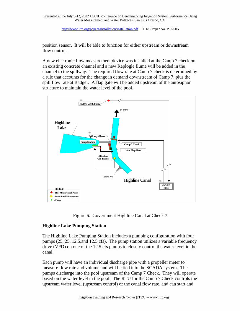
The Camp 7 check is a key structure under new operational procedures. The layout of the Camp 7 check structure and Highline Lake is shown in Figure 6. The Government Highline Canal will be operated under downstream control beyond this point. This Camp 7 check will serve as a new flow rate regulating structure. It will essentially serve as the first check for a new canal section. The check structure will be automated with a new RTU, water level sensors and gate
Irrigation Training and Research Center (ITRC) – www.itrc.org
Presented at the July 9-12, 2002 USCID conference on Benchmarking Irrigation System Performance Using Water Measurement and Water Balances. San Luis Obispo, CA.
http://www.itrc.org/papers/installation/installation.pdf ITRC Paper No. P02-005
position sensor. It will be able to function for either upstream or downstream flow control.
A new electronic flow measurement device was installed at the Camp 7 check on an existing concrete channel and a new Replogle flume will be added in the channel to the spillway. The required flow rate at Camp 7 check is determined by a rule that accounts for the change in demand downstream of Camp 7, plus the spill flow rate at Badger. A flap gate will be added upstream of the autosiphon structure to maintain the water level of the pool.
4 Pipelines with 4 meters
Highline Lake
Turnout A48
- Flow Measurement Points
Highline Canal
LEGEND
- Pump - Water Level Measurement
GVWUA Office
FLOW
Pump Station Spillway /Flume
Badger Wash Flume
Camp 7 Check
New Flap Gate
Figure 6. Government Highline Canal at Check 7
Highline Lake Pumping Station
The Highline Lake Pumping Station includes a pumping configuration with four pumps (25, 25, 12.5,and 12.5 cfs). The pump station utilizes a variable frequency drive (VFD) on one of the 12.5 cfs pumps to closely control the water level in the canal.
Each pump will have an individual discharge pipe with a propeller meter to measure flow rate and volume and will be tied into the SCADA system. The pumps discharge into the pool upstream of the Camp 7 Check. They will operate based on the water level in the pool. The RTU for the Camp 7 Check controls the upstream water level (upstream control) or the canal flow rate, and can start and
Irrigation Training and Research Center (ITRC) – www.itrc.org

Presented at the July 9-12, 2002 USCID conference on Benchmarking Irrigation System Performance Using Water Measurement and Water Balances. San Luis Obispo, CA.
http://www.itrc.org/papers/installation/installation.pdf ITRC Paper No. P02-005
stop pumps to maintain a water level. The control can change from upstream water level control to flow rate control “at the click of a button” by the operator at the GVWUA office. What makes this possible is proper programming of the RTU, measurement of the upstream water level, measurement of the flow rate, measurement of the gate position, limitations to gate travel, and a method of raising and lowering the gate. The only difference between this and any other automatically controlled check structure is that pumps are controlled, both upstream level and flow rate are measured, and programming for three functions are required.
Badger Wash Check
This is the end of the Government Highline Canal. Refer to Figure 7 for a general layout of the site. The modifications to this structure will include the addition of a Replogle flume to monitor spill flow rate and volume, a water level sensor to monitor the upstream water level and rehabilitation of one of the two existing gates (including actuator), limit switches, and a position sensor to provide automatic upstream water level control.
Lateral A57
Overflow weirs43 ft total length
Old automated gate
Manual sluice gate
Badger Wash
Spillway
Figure 7. Badger Wash Check and Spill
SUMMARY
In summary, the modernization steps to the Government Highline Canal emphasized simple solutions for the new control strategy necessary to maintain the current level of water delivery service, yet have less spill.
The results of the project will be that about 28,500 acre-feet of water can be used for the 15-Mile Reach of the Colorado River (located above the Gunnison River
Irrigation Training and Research Center (ITRC) – www.itrc.org

Presented at the July 9-12, 2002 USCID conference on Benchmarking Irrigation System Performance Using Water Measurement and Water Balances. San Luis Obispo, CA.
http://www.itrc.org/papers/installation/installation.pdf ITRC Paper No. P02-005
and Colorado River). These additional flows aid in the restoration of habitat for fish species identified as endangered.
REFERENCES
Bureau of Reclamation. 1998. “Grand Valley Water Management - Making Efficiency Improvements to the Government Highline Canal and Delivering Surplus Water from Green Mountain Reservoir to the Grand Valley Hydropower Plant”. Final Environmental Assessment. Western Colorado Area Office, Grand Junction, Colorado.
Styles, S.W., C.M. Burt, R.D. Khalsa and R. Norman. 1999. Case Study: Modernization of the Government Highline Canal. Presented at the USCID Workshop on Modernization of Irrigation Water Delivery Systems. Oct. 17-21, 1999. Phoenix, Arizona.
Irrigation Training and Research Center (ITRC) – www.itrc.org