Case study- Assignment Relates to the Overall Performances on Starter Motor against the Yoke...
53
ENGINEERING DEPARTMENT Lim Zhen Xing (FA Engineer) Department: BNA Employment Code: 13071015 Case Study: Assignment Relates to the Overall Performances on Starter Motor against the Yoke Assembly Housing and the Front Housing on the Position Marking Lock Submission date: 11 th NOVEMBER 2015 Mr. Teh (Quality Control Manager)
-
Upload
anzis-lim- -
Category
Documents
-
view
52 -
download
1
Transcript of Case study- Assignment Relates to the Overall Performances on Starter Motor against the Yoke...

ENGINEERING DEPARTMENT
Lim Zhen Xing (FA Engineer)Department: BNA
Employment Code: 13071015
Case Study: Assignment Relates to the Overall Performances on Starter Motor against the Yoke Assembly Housing and the Front Housing on the Position
Marking Lock
Submission date: 11th NOVEMBER 2015
Mr. Teh (Quality Control Manager)

Assignment Relates to the Overall Performances on Starter Motor against the Yoke Assembly Housing and the Front Housing on the Position Marking Lock.
TABLE OF CONTENTS
TABLE OF CONTENTS................................................................................................................................................ ii
LIST OF FIGURES........................................................................................................................................................ iv
LIST OF TABLES......................................................................................................................................................... iv
1. Introduction.........................................................................................................................................................1
1.2 Aim.................................................................................................................................................................2
Check and draw all of the dimensions on the starter motor rear housing cover;..............................................2
Determine the practical results on overall starter motor performances after modifications..........................2
2. Facilities/ Equipment............................................................................................................................................3
3. Initial Analysis...........................................................................................................................................................5
3.1 Check and Draw All of the dimensions on the Starter Motor Rear Housing Cover..........................................5
4. Determine the practical results on overall starter motor performances after modifications..........................6
5. Conclusions..........................................................................................................................................................12
APPENDICES..................................................................................................................................................................... I
APPENDIX 1: The Technical Specifications – OEM Starter Motor (Manufacturing No. : S14 -413 & OEM No.
23300-EB71B)............................................................................................................................................................ I
APPENDIX 2: Previous Drawing Dimension from One of the Aftermarket Manufacturers..................................II
APPENDIX 3: The Updated Results from the Coordinate Measuring Machine (CMM) after Measurement........III
APPENDIX 4 The Latest Drawing Dimensions After Modification on Rear Housing Cover.................................IV
APPENDIX 5: The Technical Specification of Computerized Starter Tester ST-16................................................V
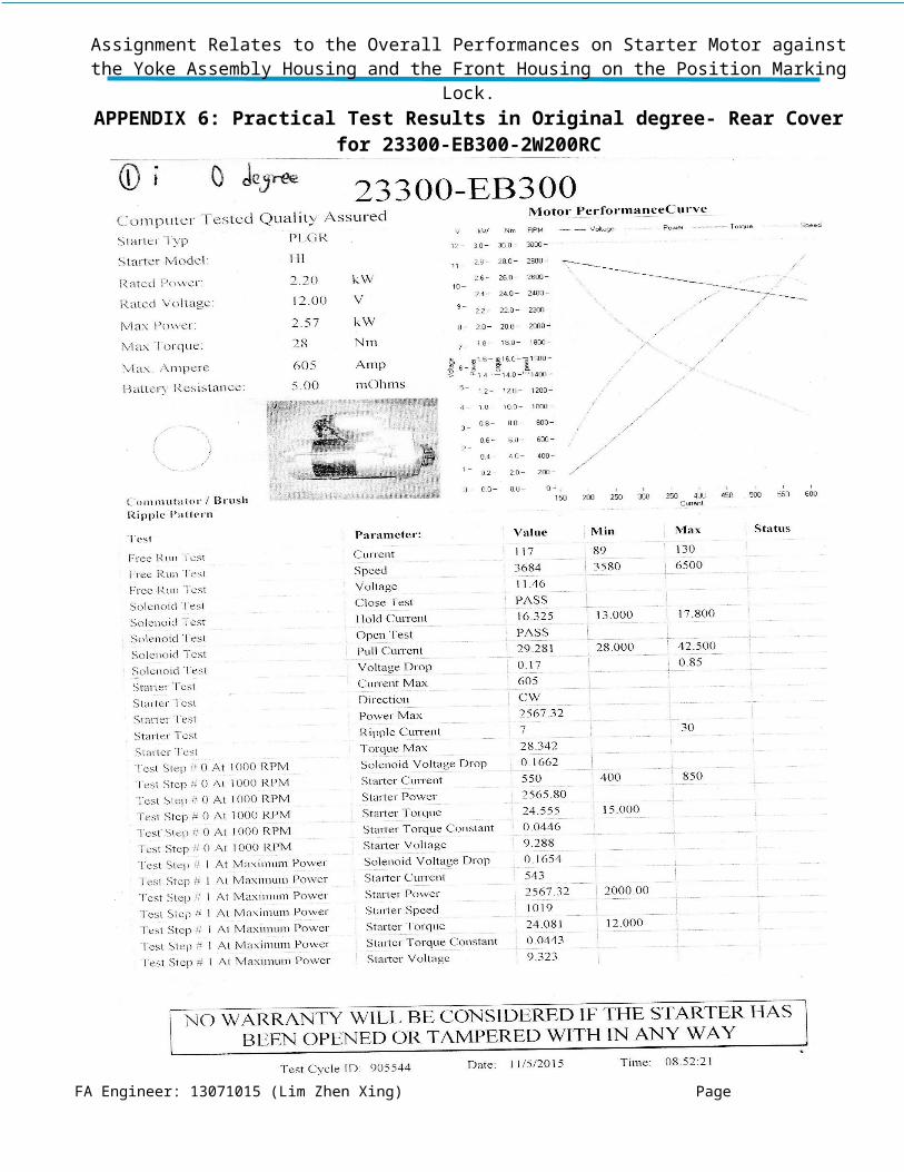
APPENDIX 6: Practical Test Results in Original degree- Rear Cover for 23300-EB300-2W200RC....................VI
APPENDIX 7: Practical Test Results in Original degree- Rear Cover for 23300-EB300-2W200RC...................VII
APPENDIX 8: Practical Test Results in Original degree- Rear Cover for 23300-EB300-2W200RC..................VIII
APPENDIX 9: Practical Test Results in Original degree- Rear Cover for 23300-EB300-2W200RC.....................IX
APPENDIX 10: Practical Test Results in 45 degree- Rear Cover for 23300-EB300-2W200RC.............................X
FA Engineer: 13071015 (Lim Zhen Xing) Page

Assignment Relates to the Overall Performances on Starter Motor against the Yoke Assembly Housing and the Front Housing on the Position Marking Lock.
APPENDIX 11: Practical Test Results in 45 degree- Rear Cover for 23300-EB300-2W200RC............................XI
APPENDIX 12: Practical Test Results in 45 degree- Rear Cover for 23300-EB300-2W200RC...........................XII
APPENDIX 13: Practical Test Results in 45 degree- Rear Cover for 23300-EB300-2W200RC..........................XIII
APPENDIX 14: Practical Test Results in 60 degree- Rear Cover for 23300-EB300-2W200RC.........................XIV
APPENDIX 15: Practical Test Results in 60 degree- Rear Cover for 23300-EB300-2W200RC..........................XV
APPENDIX 16: Practical Test Results in 60 degree- Rear Cover for 23300-EB300-2W200RC.........................XVI
APPENDIX 17: Practical Test Results in 60 degree- Rear Cover for 23300-EB300-2W200RC........................XVII
APPENDIX 18: DV Electronics Ltd. – Computerized Starter Tester ST16 Test Results on Starter Motor.......XVIII
FA Engineer: 13071015 (Lim Zhen Xing) Page

Assignment Relates to the Overall Performances on Starter Motor against the Yoke Assembly Housing and the Front Housing on the Position Marking Lock.
LIST OF FIGURES
Figure 1. Top view of the position marking lock at the OEM starter motor front housing..............................................1
Figure 2 Top view of the position marking lock at the OEM starter motor yoke assembly housing...............................1
Figure 3. Behind view of the modification multi-angle rear housing cover starter motor which follow back both of the
screws position and ground copper cable harness seat at brush holder............................................................................2
Figure 4(a) The measurement process of starter motor rear housing cover on the CMM & Figure4 (b) The enlarged
view of measurement process........................................................................................................................................5
Figure 5. The degree angle setup screw holes on the rear housing cover.......................................................................6
Figure 6. Graph of the Maximum Power, Torque and Ampere against Different Rear Housing Cover Setup Angles.. . .7
Figure 7. Graph of the Mean Maximum Power, Torque and Ampere against Different Mean Values Rear Housing
Cover Setup Angles.........................................................................................................................................................7
Figure 8. Graph of the Free Run Test on Current, Speed and Voltage against Different Rear Housing Cover Setup
Angles.............................................................................................................................................................................8
Figure 9. Graph of the Solenoid Test on Hold Current, Pull Current and Voltage Drop against Different Rear Housing
Cover Setup Angles.........................................................................................................................................................8
Figure 10. Graph of Starter test on Current Max. , Power Max., Ripple Current and Torque Max against Different Rear
Housing Cover Setup Angles..........................................................................................................................................9
Figure 11. Graph of The Test Step #0 at 1000 RPM on Solenoid Voltage Drop, Starter Current, Starter Power, Starter
Torque, Starter Torque Constant and Starter Voltage against Different Rear Housing Cover Setup Angles.................10
Figure 12. Graph of the Test Step #0 at Maximum Power on Solenoid Voltage Drop, Starter Current, Starter Power,
Starter Speed, Starter Torque, Starter Torque Constant and Starter Voltage against Different Rear Housing Cover
Setup Angles.................................................................................................................................................................11
LIST OF TABLES
Table 1. Facilities/ Equipment require in this experiment...............................................................................................4
FA Engineer: 13071015 (Lim Zhen Xing) Page

Assignment Relates to the Overall Performances on Starter Motor against the Yoke Assembly Housing and the Front Housing on the Position Marking Lock.
1. IntroductionAt the yoke assembly housing and the front housing of the starter motor, these position marking lock are always
provided in Original Equipment Manufacturer (OEM). This position marking lock is shown in the Figure 1 and
2. Sometimes the Marketing Purchasing Department is taken to the consideration in economic effect and
considered to purchase the yoke assembly or the front housing of the starter motor from the different suppliers.
This is very important and quite practical on aftermarket starter motors, either the manufacturers do not provide
this position marking lock or some minor deviation setup on both of the housing. The researcher has to identify
whether any different angles installation would be affect the performances on the starter motor.
Figure 1. Top view of the position marking lock at the OEM starter motor front housing
FA Engineer: 13071015 (Lim Zhen Xing) Page
Assignment Relates to the Overall Performances on Starter Motor against the Yoke Assembly Housing and the Front Housing on the Position Marking Lock.
Figure 2 Top view of the position marking lock at the OEM starter motor yoke assembly housing
1.2 AimThis part of the assignment relates to overall performances on the starter motor against the comparison between
different angles at the rear housing cover starter motor and the origin position marking lock. At the same times,
the rear housing cover works as the whole assembly with the both of the screws position on brush holder and
the ground copper cable harness seat for the yoke assembly housing as presented in Figure 3.
Figure 3. Behind view of the modification multi-angle rear housing cover starter motor which follow back both of the screws position and ground copper cable harness seat at brush holder
Objectives
This research is focused on two main study aspects as follow:
Check and draw all of the dimensions on the starter motor rear housing cover;
Determine the practical results on overall starter motor performances after modifications.
FA Engineer: 13071015 (Lim Zhen Xing) Page

Assignment Relates to the Overall Performances on Starter Motor against the Yoke Assembly Housing and the Front Housing on the Position Marking Lock.
2. Facilities/ Equipment
After the discussion, the EVERSPARK’s Brand New Department (BND) decided to apply for the Starter Motor
- OEM No.: 23300-EB71B [APPENDIX 1]. In this experiment, the researcher is applied in origin position
marking grove, 45 degree and 60 degree angles parallel at the fixed point of rear housing cover [APPENDIX 4].
The facilities/ Equipment are set out in Table 1.
FA Engineer: 13071015 (Lim Zhen Xing) Page

Assignment Relates to the Overall Performances on Starter Motor against the Yoke Assembly Housing and the Front Housing on the Position Marking Lock.
FA Engineer: 13071015 (Lim Zhen Xing) Page
Facilities/ Equipment Quantity
Brown & Sharpe Global Classic SR- Hexagon Metrology Coordinate Measuring Machine (CMM)
1
Previous: 2-Dimensional Drawing Dimension Reference from one
the Aftermarket Manufacturers [APPENDIX 2]
1
Latest:After Modification Multi-Angle 2-Dimension SolidWorks
Drawing Reference [APPENDIX 4]
1
DV Electronics Ltd. – Computerized Starter Tester ST16 [APPENDIX 5]
1

Assignment Relates to the Overall Performances on Starter Motor against the Yoke Assembly Housing and the Front Housing on the Position Marking Lock.
Table 1. Facilities/ Equipment require in this experiment
3. Initial Analysis
To minimize the deviation, the researcher is required to make sure that all the dimensions are absolutely correct
whether on the rear housing cover of the OEM starter or the previous 2-Dimension drawing reference from one
of the aftermarket manufacturers [APPENDIX 2].
3.1 Check and Draw All of the dimensions on the Starter Motor Rear Housing Cover
Therefore, the comparisons between both of the measurement results are needed. The precise measurement
generally collects from Coordinate Measuring Machine (CMM) are shown in Figure 4(a) and 4(b).
(a) (b)
Figure 4(a) The measurement process of starter motor rear housing cover on the CMM & Figure4 (b) The enlarged view of measurement process
FA Engineer: 13071015 (Lim Zhen Xing) Page

Assignment Relates to the Overall Performances on Starter Motor against the Yoke Assembly Housing and the Front Housing on the Position Marking Lock.
When received the results from the CMM, the researcher is required to find out the average of the dimension
deviation [APPENDIX 3]. To support the design software of the starter motor rear housing cover, the
SolidWorks 2013 executes under this modification [APPENDIX 4]. To accelerate the testing process, the BNS
sent out the latest drawing dimension paper to build the latest modification mould. The mould takes only 4 days
on progression, the project is under control.
4. Determine the practical results on overall starter motor performances after
modifications
To identify the reliable results, the DV Electronics Ltd. – Computerized Starter Tester ST16 has been employed
in this experiment [APPENDIX 5]. The researcher had simulated with Maximum Power, Maximum Torque,
Maximum Amperes, Free Run Test, Solenoid Test, Test Step #0 at 1000 RPM and Test Step #0 at Maximum
Power being altered in 3 different degree angles, all of the results are shown in Figure 5 till Figure 11. To
ensure that the starter motor is fully cool down in the winding and wiring harness under this test, the interval
between test 1, 2, 3 and so on are 50 minutes to 1 hour. Conversely, check the performances on starter motor
after heat up the test of i. and ii. are continuance. All of the results are fulfil the technical specification and pass
the test [APPENDIX 18].
In the test No. 1 and 2, both of the screws are match to the original degree setting whereas the test 3 and 4 have
placed on the 45° start from the origin without change the position on the brush holder and the yoke assembly
housing works as the whole assembly. When comes to the test 5 and 6, the algorithm on 60° is the interval
between 45° and the next screw holes so that the total degree angle measure from the origin is 45°+60° = 105°
provided in Figure
FA Engineer: 13071015 (Lim Zhen Xing) Page

Assignment Relates to the Overall Performances on Starter Motor against the Yoke Assembly Housing and the Front Housing on the Position Marking Lock.
Figure 5. The degree angle setup screw holes on the rear housing cover
The graph of this experiment shows the maximum power, torque and ampere against different rear housing
cover setup angles, as given in Figure 4. The results of this experiment indicate that the values of maximum
power and torque are remained constant whereas maximum ampere has no substantial change when increasing
of the angles. It is apparent from the Figure 5 till Figure 11 that there are small fluctuations on the results,
therefore the tightness between the connection cables from the test machine to the starter motor are under
consideration. This direct affect the small changing from the results but it is still acceptable.
FA Engineer: 13071015 (Lim Zhen Xing) Page

Assignment Relates to the Overall Performances on Starter Motor against the Yoke Assembly Housing and the Front Housing on the Position Marking Lock.
Figure 6. Graph of the Maximum Power, Torque and Ampere against Different Rear Housing Cover Setup Angles
Figure 7. Graph of the Mean Maximum Power, Torque and Ampere against Different Mean Values Rear Housing Cover Setup Angles
FA Engineer: 13071015 (Lim Zhen Xing) Page

Assignment Relates to the Overall Performances on Starter Motor against the Yoke Assembly Housing and the Front Housing on the Position Marking Lock.
Figure 8. Graph of the Free Run Test on Current, Speed and Voltage against Different Rear Housing Cover Setup Angles
Figure 9. Graph of the Solenoid Test on Hold Current, Pull Current and Voltage Drop against Different Rear Housing Cover Setup Angles
FA Engineer: 13071015 (Lim Zhen Xing) Page

Assignment Relates to the Overall Performances on Starter Motor against the Yoke Assembly Housing and the Front Housing on the Position Marking Lock.
Figure 10. Graph of Starter test on Current Max. , Power Max., Ripple Current and Torque Max against Different Rear Housing Cover Setup Angles
FA Engineer: 13071015 (Lim Zhen Xing) Page

Assignment Relates to the Overall Performances on Starter Motor against the Yoke Assembly Housing and the Front Housing on the Position Marking Lock.
Figure 11. Graph of The Test Step #0 at 1000 RPM on Solenoid Voltage Drop, Starter Current, Starter Power, Starter Torque, Starter Torque Constant and Starter Voltage against Different Rear Housing
Cover Setup AnglesFA Engineer: 13071015 (Lim Zhen Xing) Page

Assignment Relates to the Overall Performances on Starter Motor against the Yoke Assembly Housing and the Front Housing on the Position Marking Lock.
Figure 12. Graph of the Test Step #0 at Maximum Power on Solenoid Voltage Drop, Starter Current, Starter Power, Starter Speed, Starter Torque, Starter Torque Constant and Starter Voltage against
Different Rear Housing Cover Setup AnglesFA Engineer: 13071015 (Lim Zhen Xing) Page

Assignment Relates to the Overall Performances on Starter Motor against the Yoke Assembly Housing and the Front Housing on the Position Marking Lock.
5. Conclusions
All of the results have passed the test. In a direct comparison are provided in Figure 5, when the rear housing
cover aligned with both of the screw holes at the brush holder and the ground copper cable harness seat for the
yoke assembly housing, the overall performances on the starter motor will not influence the improperly
installation of the yoke assembly housing and the front housing on the position marking lock. These results are
vital, it allows the installation becomes easier and improves the assembly duration on starter motor.
FA Engineer: 13071015 (Lim Zhen Xing) Page

Assignment Relates to the Overall Performances on Starter Motor against the Yoke Assembly Housing and the Front Housing on the Position Marking Lock.
APPENDICES
APPENDIX 1: The Technical Specifications – OEM Starter Motor (Manufacturing No. : S14 -413 & OEM No. 23300-EB71B)
FA Engineer: 13071015 (Lim Zhen Xing) Page

Assignment Relates to the Overall Performances on Starter Motor against the Yoke Assembly Housing and the Front Housing on the Position Marking Lock.
APPENDIX 2: Previous Drawing Dimension from One of the Aftermarket Manufacturers
FA Engineer: 13071015 (Lim Zhen Xing) Page

Assignment Relates to the Overall Performances on Starter Motor against the Yoke Assembly Housing and the Front Housing on the Position Marking Lock.
APPENDIX 3: The Updated Results from the Coordinate Measuring Machine (CMM) after Measurement
FA Engineer: 13071015 (Lim Zhen Xing) Page

Assignment Relates to the Overall Performances on Starter Motor against the Yoke Assembly Housing and the Front Housing on the Position Marking Lock.
APPENDIX 4 The Latest Drawing Dimensions After Modification on Rear Housing Cover
FA Engineer: 13071015 (Lim Zhen Xing) Page

Assignment Relates to the Overall Performances on Starter Motor against the Yoke Assembly Housing and the Front Housing on the Position Marking Lock.
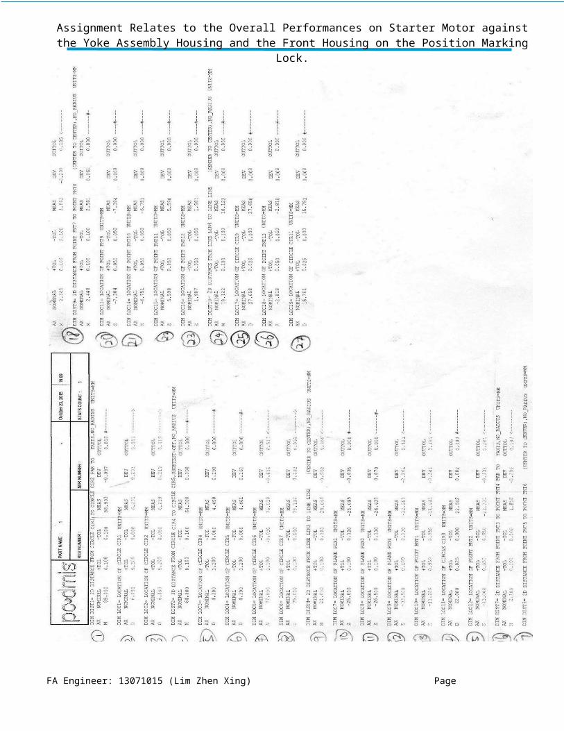
APPENDIX 5: The Technical Specification of Computerized Starter Tester ST-16
FA Engineer: 13071015 (Lim Zhen Xing) Page

Assignment Relates to the Overall Performances on Starter Motor against the Yoke Assembly Housing and the Front Housing on the Position Marking Lock.
APPENDIX 6: Practical Test Results in Original degree- Rear Cover for 23300-EB300-2W200RC
FA Engineer: 13071015 (Lim Zhen Xing) Page

Assignment Relates to the Overall Performances on Starter Motor against the Yoke Assembly Housing and the Front Housing on the Position Marking Lock.
APPENDIX 7: Practical Test Results in Original degree- Rear Cover for 23300-EB300-2W200RC
FA Engineer: 13071015 (Lim Zhen Xing) Page

Assignment Relates to the Overall Performances on Starter Motor against the Yoke Assembly Housing and the Front Housing on the Position Marking Lock.
APPENDIX 8: Practical Test Results in Original degree- Rear Cover for 23300-EB300-2W200RC
FA Engineer: 13071015 (Lim Zhen Xing) Page

Assignment Relates to the Overall Performances on Starter Motor against the Yoke Assembly Housing and the Front Housing on the Position Marking Lock.
APPENDIX 9: Practical Test Results in Original degree- Rear Cover for 23300-EB300-2W200RC
FA Engineer: 13071015 (Lim Zhen Xing) Page

Assignment Relates to the Overall Performances on Starter Motor against the Yoke Assembly Housing and the Front Housing on the Position Marking Lock.
APPENDIX 10: Practical Test Results in 45 degree- Rear Cover for 23300-EB300-2W200RC
FA Engineer: 13071015 (Lim Zhen Xing) Page
Assignment Relates to the Overall Performances on Starter Motor against the Yoke Assembly Housing and the Front Housing on the Position Marking Lock.
APPENDIX 11: Practical Test Results in 45 degree- Rear Cover for 23300-EB300-2W200RC
FA Engineer: 13071015 (Lim Zhen Xing) Page

Assignment Relates to the Overall Performances on Starter Motor against the Yoke Assembly Housing and the Front Housing on the Position Marking Lock.
APPENDIX 12: Practical Test Results in 45 degree- Rear Cover for 23300-EB300-2W200RC
FA Engineer: 13071015 (Lim Zhen Xing) Page

Assignment Relates to the Overall Performances on Starter Motor against the Yoke Assembly Housing and the Front Housing on the Position Marking Lock.
APPENDIX 13: Practical Test Results in 45 degree- Rear Cover for 23300-EB300-2W200RC
FA Engineer: 13071015 (Lim Zhen Xing) Page

Assignment Relates to the Overall Performances on Starter Motor against the Yoke Assembly Housing and the Front Housing on the Position Marking Lock.
APPENDIX 14: Practical Test Results in 60 degree- Rear Cover for 23300-EB300-2W200RC
FA Engineer: 13071015 (Lim Zhen Xing) Page
Assignment Relates to the Overall Performances on Starter Motor against the Yoke Assembly Housing and the Front Housing on the Position Marking Lock.
APPENDIX 15: Practical Test Results in 60 degree- Rear Cover for 23300-EB300-2W200RC
FA Engineer: 13071015 (Lim Zhen Xing) Page
Assignment Relates to the Overall Performances on Starter Motor against the Yoke Assembly Housing and the Front Housing on the Position Marking Lock.
APPENDIX 16: Practical Test Results in 60 degree- Rear Cover for 23300-EB300-2W200RC
FA Engineer: 13071015 (Lim Zhen Xing) Page

Assignment Relates to the Overall Performances on Starter Motor against the Yoke Assembly Housing and the Front Housing on the Position Marking Lock.
APPENDIX 17: Practical Test Results in 60 degree- Rear Cover for 23300-EB300-2W200RC
FA Engineer: 13071015 (Lim Zhen Xing) Page

Assignment Relates to the Overall Performances on Starter Motor against the Yoke Assembly Housing and the Front Housing on the Position Marking Lock.
APPENDIX 18: DV Electronics Ltd. – Computerized Starter Tester ST16 Test Results on Starter Motor Computer Setup Test No. (*OEM No.: 23300-EB71B) 23300-EB300Starter Type: PLGRStarter Model: HIRated Power: 2.2 kWRated Voltage: 12 VBattery Resistance 5 mOhms
1) i. 0 degree 1) ii. 0 degree 2) i. 0 degree 2) ii. 0 degree 3) i. 45 degree 3) ii. 45 degree 4) i. 45 degree 4) ii. 45 degree 5) i. 60 degree 5) ii. 60 degree 6) i. 60 degree 6) ii. 60 degreeMax. Power (kW) 2.57 2.43 2.52 2.68 2.52 2.45 2.74 2.55 2.44 2.43 2.6 2.47Max. Torque (Nm) 28 27 28 30 28 27 30 28 27 27 29 28
Max. Ampere (Amp) 605 601 605 631 632 611 631 611 601 601 623 611
1) i. 0 degree 1) ii. 0 degree 2) i. 0 degree 2) ii. 0 degree 3) i. 45 degree 3) ii. 45 degree 4) i. 45 degree 4) ii. 45 degree 5) i. 60 degree 5) ii. 60 degree 6) i. 60 degree 6) ii. 60 degreeFree Run Test (Current) 117 118 116 118 126 117 129 123 126 118 128 120Free Run Test (Speed) 3684 3736 3887 3687 3688 3975 3633 3842 3634 3900 3689 3949Free Run Test (Voltage) 11.46 11.41 11.42 11.43 11.4 11.45 11.4 11.41 11.4 11.41 11.39 11.41Solenoid Test (Hold Current) 16.325 14.948 15.792 17.615 17.44 15.765 17.784 16.04 17.527 15.58 17.744 15.966Solenoid Test (Pull Current) 29.281 28.235 29.715 30.93 31.242 29.672 31.675 30.267 30.679 29.517 31.268 29.917Solenoid Test (Voltage Drop) 0.17 0.14 0.17 0.18 0.26 0.22 0.27 0.41 0.25 0.13 0.25 0.217Starter Test (Current Max) 605 601 605 631 632 611 631 611 601 601 623 611Starter Test (Power Max) 2567.32 2433.57 2520.85 2678.19 2517.44 2451.04 2738.82 2554.23 2439.03 2425.26 2603.5 2469.31Starter Test (Ripple Current) 7 8 7 8 9 9 9 8 8 9 8 8Starter Test (Torque Max) 28.342 27.197 27.731 29.914 28.357 27.059 30.343 28.418 27.33 27.009 29.086 27.635Test Step #0 at 1000 RPM (Solenoid Voltage Drop) 0.1662 0.1257 0.164 0.1574 0.2294 0.2008 0.2393 0.3934 0.2155 0.1191 0.2302 0.2292Test Step #0 at 1000 RPM (Starter Current) 550 543 548 570 567 552 572 552 541 543 562 554Test Step #0 at 1000 RPM (Starter Power) 2565.8 2433.54 2512 2677.88 2517.06 2445.86 2738.79 2552.84 2438.65 2423.09 2603.21 2469.07Test Step #0 at 1000 RPM (Starter Torque) 24.555 23.314 24.048 25.616 24.089 23.417 26.177 24.419 23.312 23.206 24.916 23.604Test Step #0 at 1000 RPM (Starter Torque Constant) 0.00446 0.0429 0.0439 0.0449 0.0425 0.0424 0.0458 0.0442 0.0431 0.0427 0.0443 0.0426Test Step #0 at 1000 RPM (Starter Voltage) 9.288 9.314 9.284 9.188 9.194 9.267 9.173 9.265 9.323 9.307 9.214 9.248Test Step #0 at Maximum Power (Solenoid Voltage Drop) 0.1654 0.1259 0.1606 0.1564 0.2309 0.1963 0.2397 0.3898 0.2131 0.117 0.2311 0.2309Test Step #0 at Maximum Power (Starter Current) 543 544 531 567 571 539 573 545 537 534 565 557Test Step #0 at Maximum Power (Starter Power) 2567.32 2433.57 2520.85 2678.19 2517.44 2451.04 2738.82 2554.23 2439.03 2425.26 2603.05 2469.31Test Step #0 at Maximum Power (Starter Speed) 1019 994 1050 1007 988 1036 997 1019 1011 1024 990 991Test Step #0 at Maximum Power (Starter Torque) 24.081 23.38 22.942 25.409 24.35 22.605 26.247 23.951 23.048 22.622 25.119 23.812Test Step #0 at Maximum Power (Starter Torque Constant) 0.0443 0.043 0.0432 0.0448 0.0426 0.0419 0.0458 0.0439 0.0429 0.0424 0.0445 0.0428Test Step #0 at Maximum Power (Starter Voltage) 9.323 9.309 9.369 9.203 9.174 9.332 9.168 9.3 9.343 9.351 9.199 9.233
Conversely, check the starter performance after heat up the test of i. and ii. are continuance.To ensure that the starter motor is fully cool down in the winding and wiring harness under this test, the interval between test 1, 2, 3 and so on are 50 minutes to 1 hour.
FA Engineer: 13071015 (Lim Zhen Xing) Page