Case Studies of Smart Sensors and Smart MEMS Devices
60
1 Case Studies of Smart Sensors and Smart MEMS Devices 3 Case Studies of Smart Sensors & Smart MEMS © 2017: Dr. H. K. Verma Dr. H. K. Verma Distinguished Professor (EEE) Sharda University, Greater Noida (Formerly: Deputy Director and Professor of Instrumentation Indian Institute of Technology Roorkee)
Transcript of Case Studies of Smart Sensors and Smart MEMS Devices
1
Case Studies of
Smart Sensors and Smart MEMS Devices
3
Case Studies of Smart Sensors & Smart MEMS © 2017: Dr. H. K. Verma
Dr. H. K. Verma
Distinguished Professor (EEE)
Sharda University, Greater Noida
(Formerly: Deputy Director and Professor of Instrumentation
Indian Institute of Technology Roorkee)
2
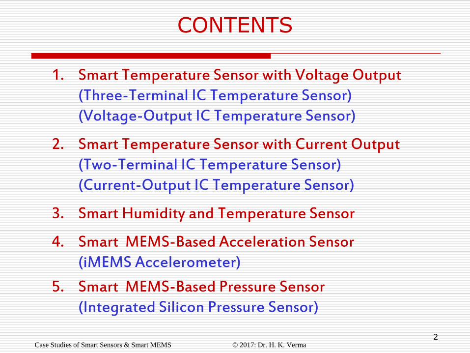
1. Smart Temperature Sensor with Voltage Output (Three-Terminal IC Temperature Sensor) (Voltage-Output IC Temperature Sensor)
2. Smart Temperature Sensor with Current Output (Two-Terminal IC Temperature Sensor) (Current-Output IC Temperature Sensor)
3. Smart Humidity and Temperature Sensor
4. Smart MEMS-Based Acceleration Sensor (iMEMS Accelerometer)
5. Smart MEMS-Based Pressure Sensor (Integrated Silicon Pressure Sensor)
Case Studies of Smart Sensors & Smart MEMS © 2017: Dr. H. K. Verma
CONTENTS
3
Case Study # 1
Smart Temperature Sensor with Voltage Output
or
Three-Terminal IC Temperature Sensor
or
Voltage-Output IC Temperature Sensor
Manufacturer: National Semiconductor Corporation
Website: www.national.com
Case Studies of Smart Sensors & Smart MEMS © 2017: Dr. H. K. Verma
4
LM35.…….
Major Specifications
Case Studies of Smart Sensors & Smart MEMS © 2017: Dr. H. K. Verma
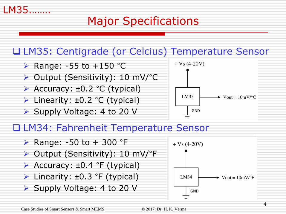
LM35: Centigrade (or Celcius) Temperature Sensor
Range: -55 to +150 °C
Output (Sensitivity): 10 mV/°C
Accuracy: ±0.2 °C (typical)
Linearity: ±0.2 °C (typical)
Supply Voltage: 4 to 20 V
LM34: Fahrenheit Temperature Sensor
Range: -50 to + 300 °F
Output (Sensitivity): 10 mV/°F
Accuracy: ±0.4 °F (typical)
Linearity: ±0.3 °F (typical)
Supply Voltage: 4 to 20 V
5
LM35.…….
Principle of LM35/LM34 (1)
Case Studies of Smart Sensors & Smart MEMS © 2017: Dr. H. K. Verma
These sensors are based on temperature sensitivity of band
gap voltage of silicon junction.
Band gap (or energy gap) is the energy range in a solid
where no free electron states can exist.
It refers to the energy gap (in electron volts, eV) between
the top of the valance band and the bottom of the
conduction band.
In other words, it is the smallest amount of energy in eV
required to free on outer-shell electron (or valance electron)
from its orbit about the nucleus to become a mobile charge
carrier (i.e. free electron).
6
LM35.…….
Principle of LM35/LM34 (2)
Case Studies of Smart Sensors & Smart MEMS © 2017: Dr. H. K. Verma
In conductors, the valance band and conduction band
overlap, hence they may not have a band gap.
In insulators, the band gap is too large to be bridged.
In semiconductors, the band gap is small. Electrons can
gain energy to jump from valance band to conduction
band by adsorbing either phonons (heat energy) or
photons (light energy).
So band gap in a semiconductor will decrease as its
temperature is raised.
7
LM35.…….
Principle of LM35/LM34 (3)
Case Studies of Smart Sensors & Smart MEMS © 2017: Dr. H. K. Verma
This property (temperature sensitivity) of
semiconductors forms the basis of all silicon
temperature sensors.
Values of band gap at 300K (i.e., 27°C) for some
semiconductors of interest are:
Si : 1.11 eV
Ge : 0.67 eV
Se : 1.74 eV
GaAs : 1.43 eV
GaP : 2.26 eV
GaS : 2.50 eV
8
LM35.…….
Principle of LM35/LM34 (4)
Case Studies of Smart Sensors & Smart MEMS © 2017: Dr. H. K. Verma
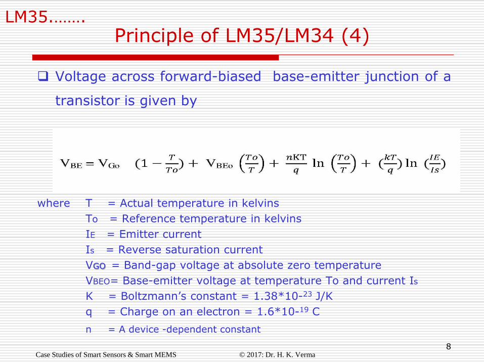
Voltage across forward-biased base-emitter junction of a
transistor is given by
where T = Actual temperature in kelvins
To = Reference temperature in kelvins
IE = Emitter current
Is = Reverse saturation current
VGO = Band-gap voltage at absolute zero temperature
VBEO= Base-emitter voltage at temperature To and current Is
K = Boltzmann’s constant = 1.38*10-23 J/K
q = Charge on an electron = 1.6*10-19 C
n = A device -dependent constant
9
LM35.…….
Principle of LM35/LM34 (5)
Case Studies of Smart Sensors & Smart MEMS © 2017: Dr. H. K. Verma
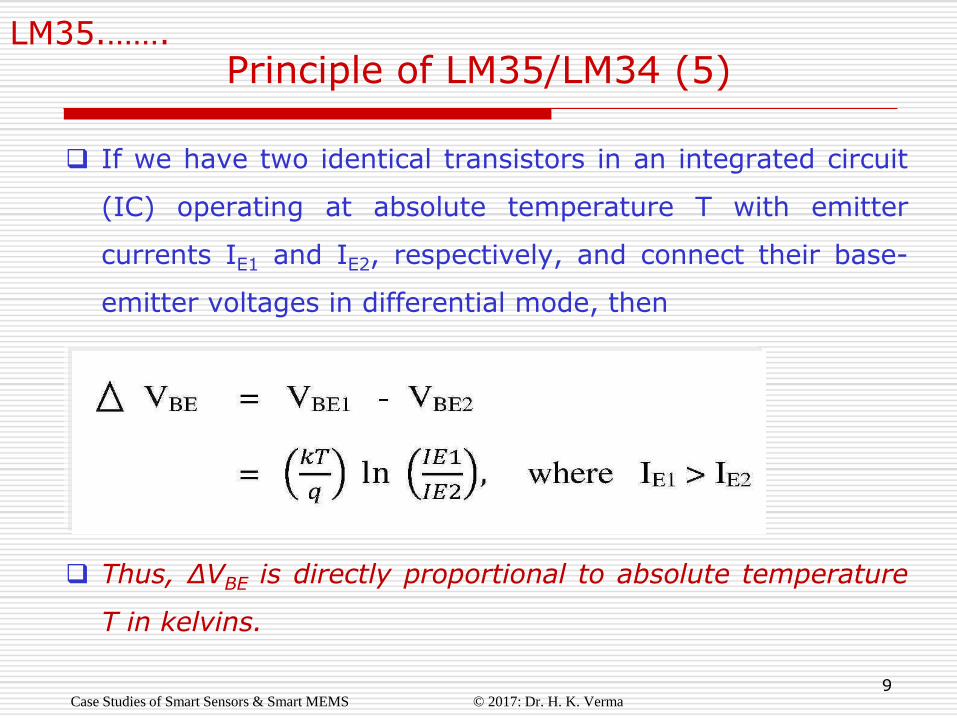
If we have two identical transistors in an integrated circuit
(IC) operating at absolute temperature T with emitter
currents IE1 and IE2, respectively, and connect their base-
emitter voltages in differential mode, then
Thus, ∆VBE is directly proportional to absolute temperature
T in kelvins.
10
LM35.…….
Design Values for LM35
Case Studies of Smart Sensors & Smart MEMS © 2017: Dr. H. K. Verma
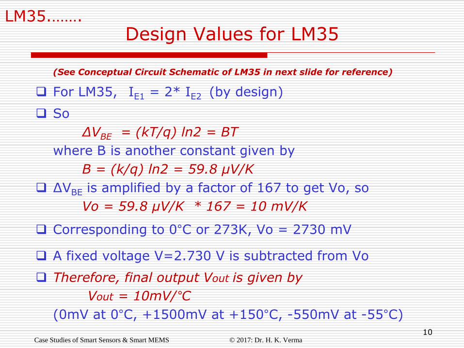
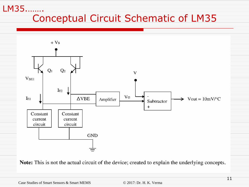
(See Conceptual Circuit Schematic of LM35 in next slide for reference)
For LM35, IE1 = 2* IE2 (by design)
So
∆VBE = (kT/q) ln2 = BT where B is another constant given by
B = (k/q) ln2 = 59.8 µV/K
∆VBE is amplified by a factor of 167 to get Vo, so
Vo = 59.8 µV/K * 167 = 10 mV/K
Corresponding to 0°C or 273K, Vo = 2730 mV
A fixed voltage V=2.730 V is subtracted from Vo
Therefore, final output Vout is given by
Vout = 10mV/°C
(0mV at 0°C, +1500mV at +150°C, -550mV at -55°C)
11
LM35.…….
Conceptual Circuit Schematic of LM35
Case Studies of Smart Sensors & Smart MEMS © 2017: Dr. H. K. Verma
12
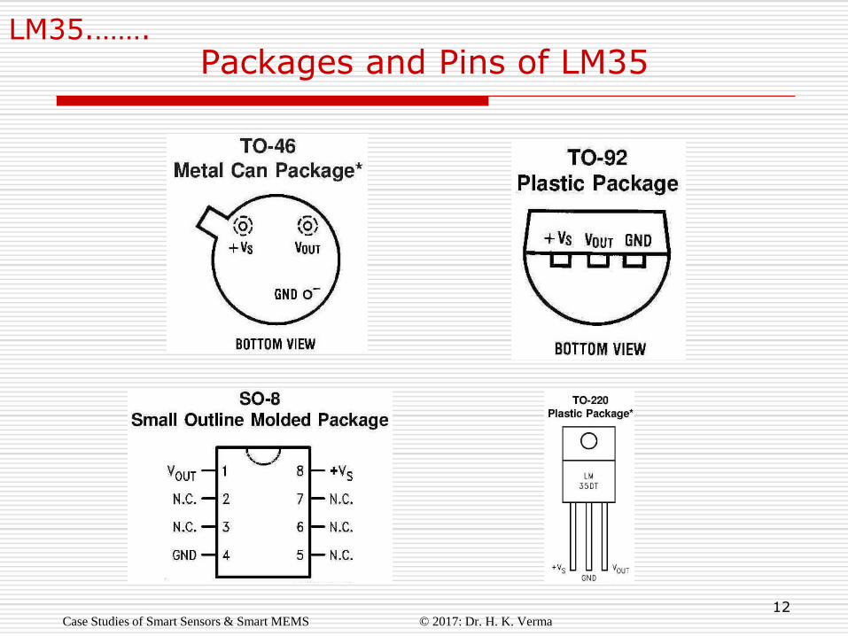
LM35.…….
Packages and Pins of LM35
Case Studies of Smart Sensors & Smart MEMS © 2017: Dr. H. K. Verma
13
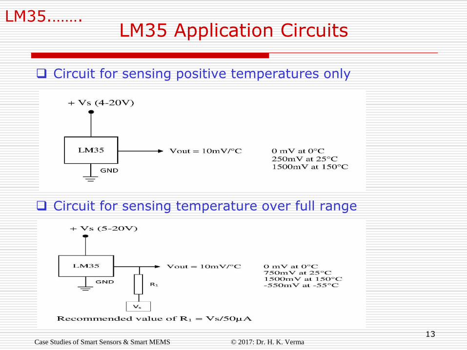
LM35.……. LM35 Application Circuits
Case Studies of Smart Sensors & Smart MEMS © 2017: Dr. H. K. Verma
Circuit for sensing positive temperatures only
Circuit for sensing temperature over full range
14
Case Study # 2
Smart Temperature Sensor with Current Output
or
Two-Terminal IC Temperature Sensor
or
Current-Output IC Temperature Sensor
Manufacturer: Analog Devices
Website: www.analog.com
Case Studies of Smart Sensors & Smart MEMS © 2017: Dr. H. K. Verma
15
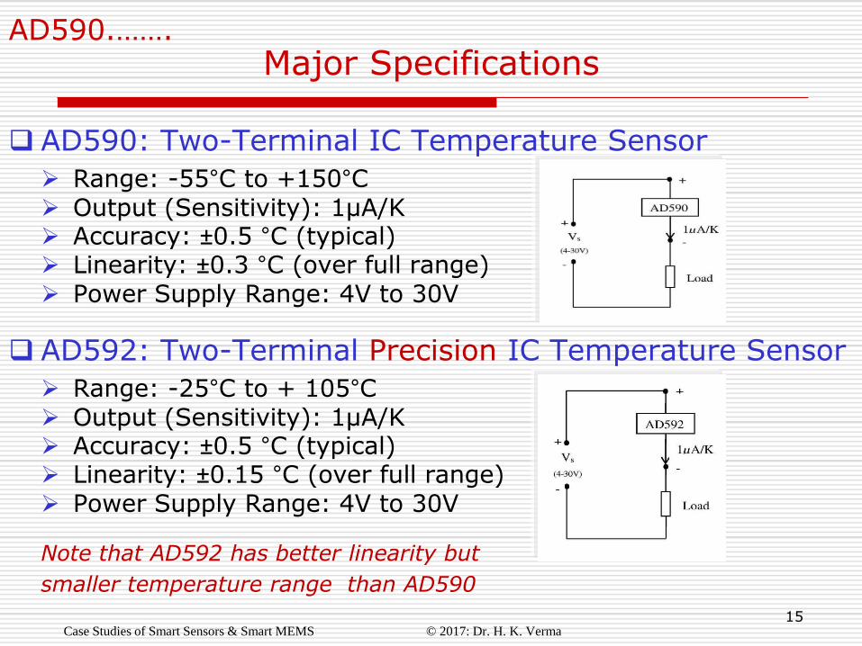
AD590.…….
Major Specifications
Case Studies of Smart Sensors & Smart MEMS © 2017: Dr. H. K. Verma
AD590: Two-Terminal IC Temperature Sensor
Range: -55°C to +150°C Output (Sensitivity): 1µA/K Accuracy: ±0.5 °C (typical) Linearity: ±0.3 °C (over full range) Power Supply Range: 4V to 30V
AD592: Two-Terminal Precision IC Temperature Sensor
Range: -25°C to + 105°C Output (Sensitivity): 1µA/K Accuracy: ±0.5 °C (typical) Linearity: ±0.15 °C (over full range) Power Supply Range: 4V to 30V
Note that AD592 has better linearity but
smaller temperature range than AD590

16
AD590.…….
Principle of AD590/592
Case Studies of Smart Sensors & Smart MEMS © 2017: Dr. H. K. Verma
These sensors, like LM35 and LM34, are also based on temperature sensitivity of band gap voltage of silicon junction. The detailed principle can be seen from the Case Study of LM35/34.
So the following equation is applicable to AD590/AD592 too:
However, ∆VBE is converted here to a proportional total device current, which is the output current signal proportional to absolute temperature T, namely
Iout = 1µA/K

17
AD590.…….
Circuit Diagram of AD590
Case Studies of Smart Sensors & Smart MEMS © 2017: Dr. H. K. Verma
(Source: Data Sheet of AD590)
18
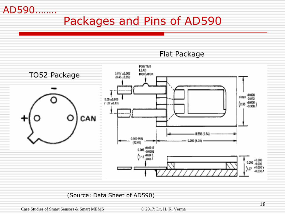
AD590.…….
Packages and Pins of AD590
TO52 Package
Flat Package
Case Studies of Smart Sensors & Smart MEMS © 2017: Dr. H. K. Verma
(Source: Data Sheet of AD590)
19
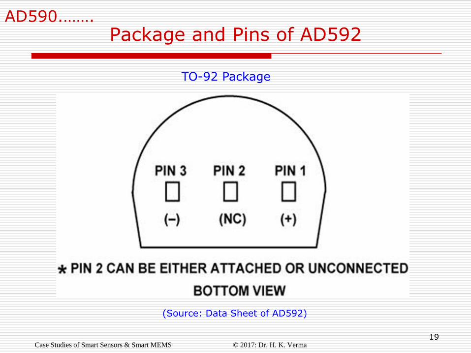
AD590.…….
Package and Pins of AD592
TO-92 Package
Case Studies of Smart Sensors & Smart MEMS © 2017: Dr. H. K. Verma
(Source: Data Sheet of AD592)
20
Case Study # 3
Smart Humidity and Temperature Sensor
Case Studies of Smart Sensors & Smart MEMS © 2017: Dr. H. K. Verma
Manufacturer: Sensirion Corporation
Website: www.sensirion.com
21
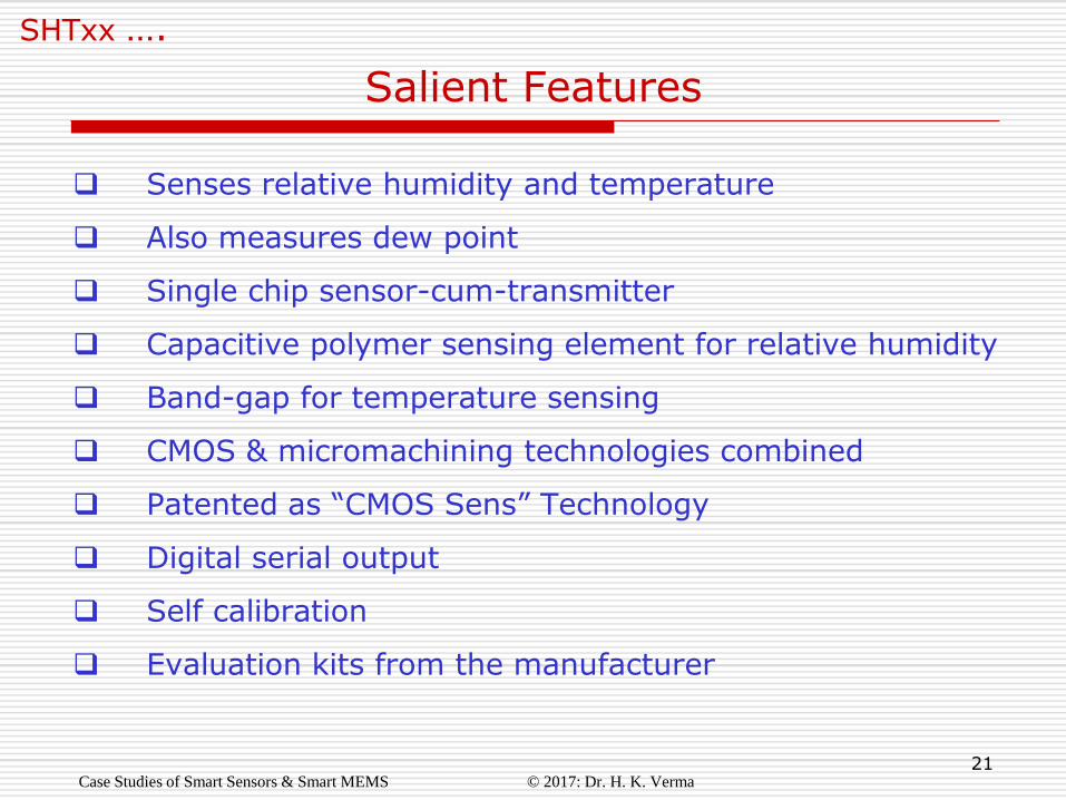
SHTxx ….
Senses relative humidity and temperature
Also measures dew point
Single chip sensor-cum-transmitter
Capacitive polymer sensing element for relative humidity
Band-gap for temperature sensing
CMOS & micromachining technologies combined
Patented as “CMOS Sens” Technology
Digital serial output
Self calibration
Evaluation kits from the manufacturer
Salient Features
Case Studies of Smart Sensors & Smart MEMS © 2017: Dr. H. K. Verma
22
SHTxx ….
o Fast response
o Ultra low power consumption
o Automatic power down feature
o Excellent long term stability
o Excellent performance-to-price ratio
o Insensitivity to external disturbance (EMC)
o Fully calibrated digital output
o Data with CRC bits
Performance Features
Case Studies of Smart Sensors & Smart MEMS © 2017: Dr. H. K. Verma
23
Devices in SHTxx Series
Case Studies of Smart Sensors & Smart MEMS © 2017: Dr. H. K. Verma
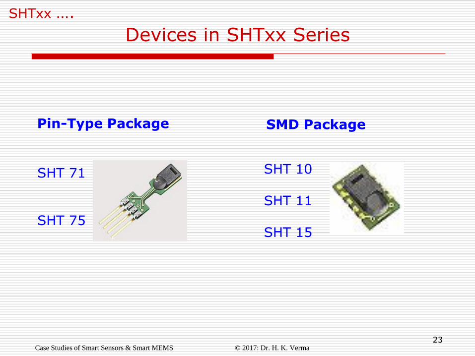
SHTxx ….
Pin-Type Package SMD Package
SHT 71 SHT 75
SHT 10 SHT 11 SHT 15
24
SHTxx ….
Technical Data
Case Studies of Smart Sensors & Smart MEMS © 2017: Dr. H. K. Verma
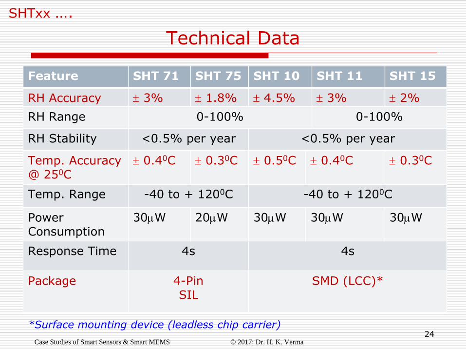
Feature SHT 71 SHT 75 SHT 10 SHT 11 SHT 15
RH Accuracy 3% 1.8% 4.5% 3% 2%
RH Range 0-100% 0-100%
RH Stability <0.5% per year <0.5% per year
Temp. Accuracy @ 250C
0.40C 0.30C 0.50C 0.40C 0.30C
Temp. Range -40 to + 1200C -40 to + 1200C
Power Consumption
30W 20W 30W 30W 30W
Response Time 4s 4s
Package 4-Pin SIL
SMD (LCC)*
*Surface mounting device (leadless chip carrier)
25
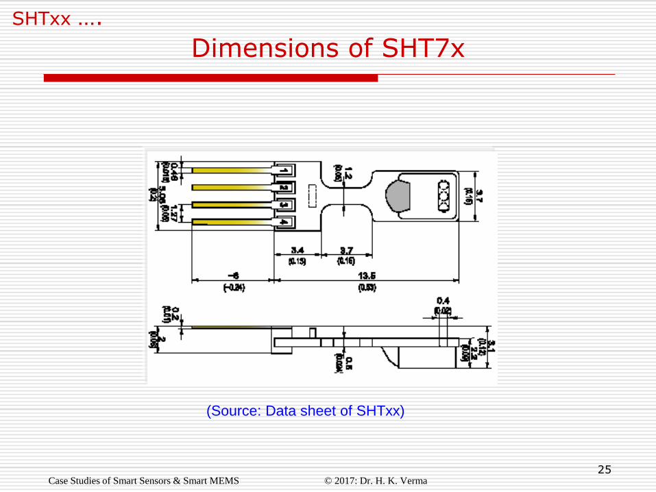
Dimensions of SHT7x
Case Studies of Smart Sensors & Smart MEMS © 2017: Dr. H. K. Verma
SHTxx ….
(Source: Data sheet of SHTxx)
26
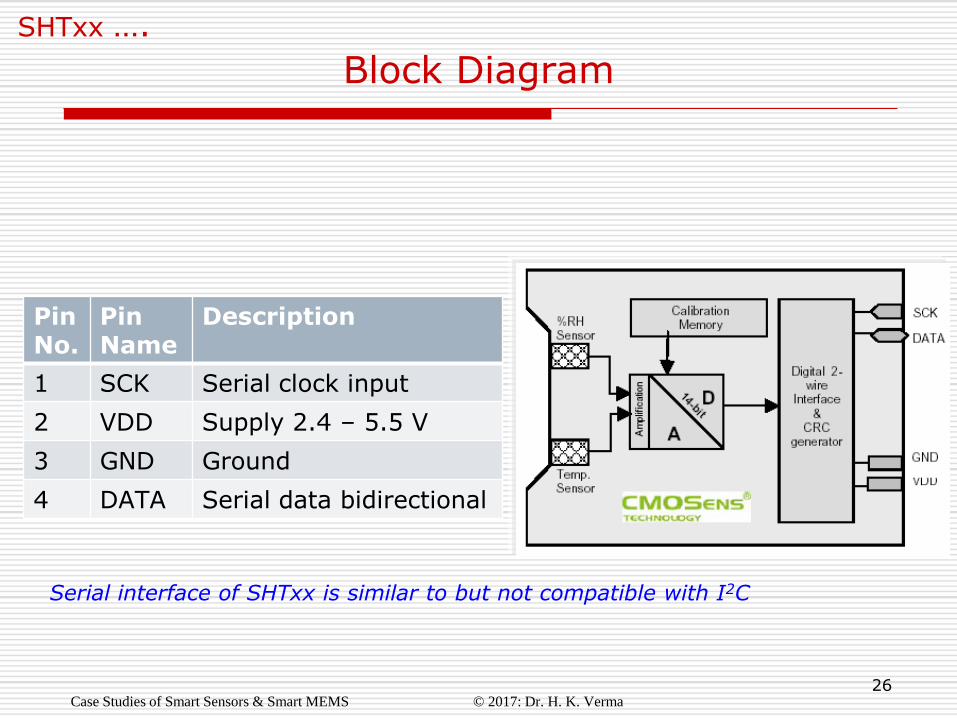
Block Diagram
Case Studies of Smart Sensors & Smart MEMS © 2017: Dr. H. K. Verma
SHTxx ….
Serial interface of SHTxx is similar to but not compatible with I2C
Pin No.
Pin Name
Description
1 SCK Serial clock input
2 VDD Supply 2.4 – 5.5 V
3 GND Ground
4 DATA Serial data bidirectional
27
Amplifiers for amplifying outputs of sensors
14-bit ADC for analog to digital conversion
Serial interface circuit for 2-wire serial transmission
8-bit CRC generator for error control
Calibration circuit for self calibration
Calibration memory for storing calibration coefficients
On-Chip Circuitry
Case Studies of Smart Sensors & Smart MEMS © 2017: Dr. H. K. Verma
SHTxx ….
28
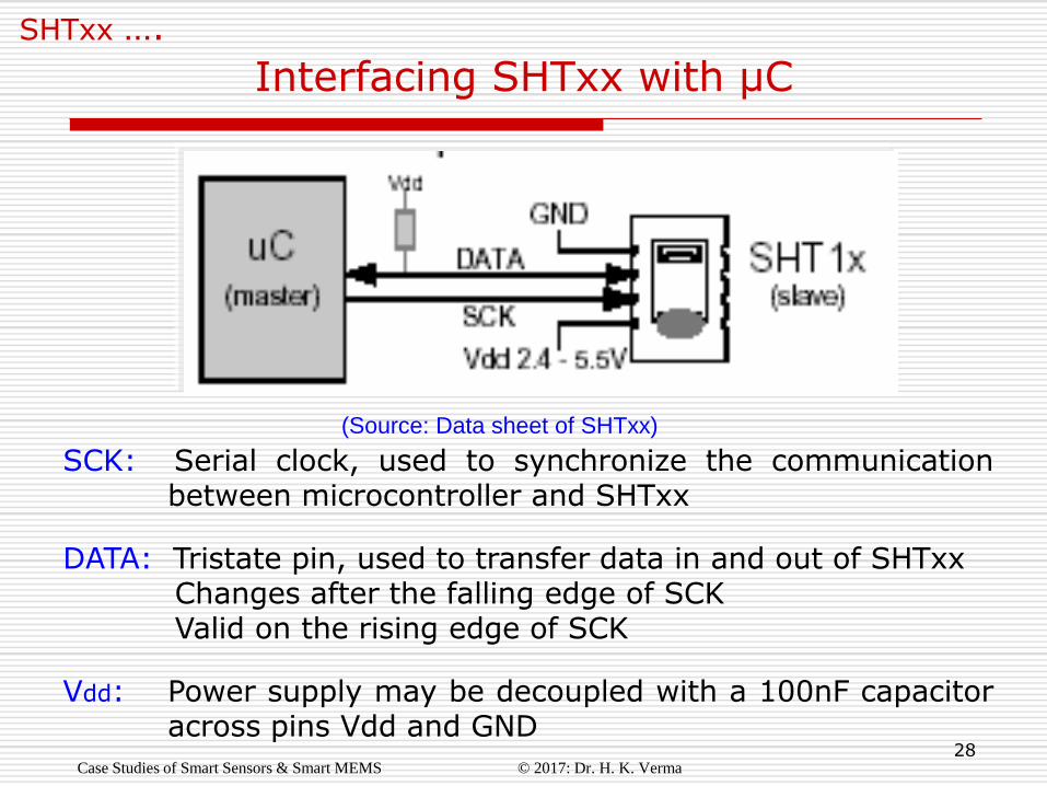
Interfacing SHTxx with µC
Case Studies of Smart Sensors & Smart MEMS © 2017: Dr. H. K. Verma
SHTxx ….
SCK: Serial clock, used to synchronize the communication between microcontroller and SHTxx
DATA: Tristate pin, used to transfer data in and out of SHTxx Changes after the falling edge of SCK Valid on the rising edge of SCK
Vdd: Power supply may be decoupled with a 100nF capacitor across pins Vdd and GND
(Source: Data sheet of SHTxx)
29
Case Study # 4
Smart Acceleration Sensor
or
iMEMS Accelerometer
Manufacturer: Analog Devices
Website: www.analog.com
Case Studies of Smart Sensors & Smart MEMS © 2017: Dr. H. K. Verma
30
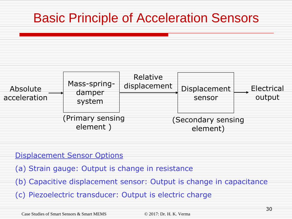
Basic Principle of Acceleration Sensors
Case Studies of Smart Sensors & Smart MEMS © 2017: Dr. H. K. Verma
Mass-spring- damper system
Electrical output
(Primary sensing element )
(Secondary sensing element)
Displacement Sensor Options
(a) Strain gauge: Output is change in resistance
(b) Capacitive displacement sensor: Output is change in capacitance
(c) Piezoelectric transducer: Output is electric charge
Displacement sensor
Relative displacement Absolute
acceleration
31
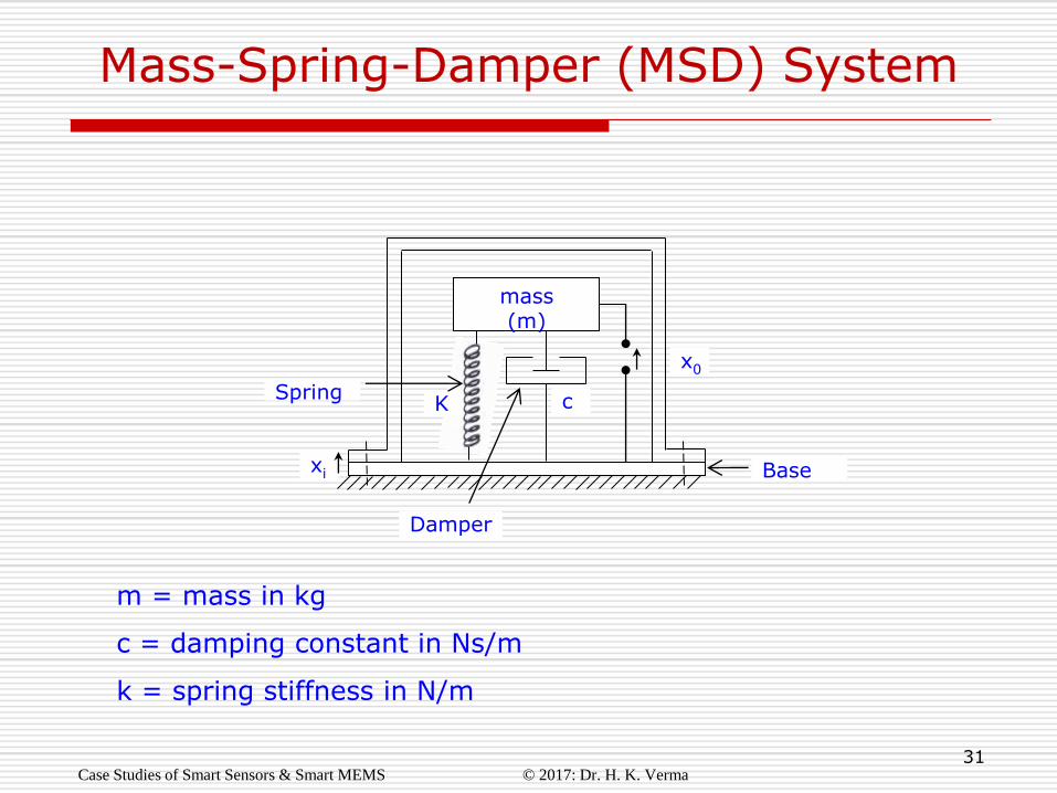
Mass-Spring-Damper (MSD) System
mass (m)
K Spring
x0
c
xi
Damper
m = mass in kg
c = damping constant in Ns/m
k = spring stiffness in N/m
Case Studies of Smart Sensors & Smart MEMS © 2017: Dr. H. K. Verma
Base
32
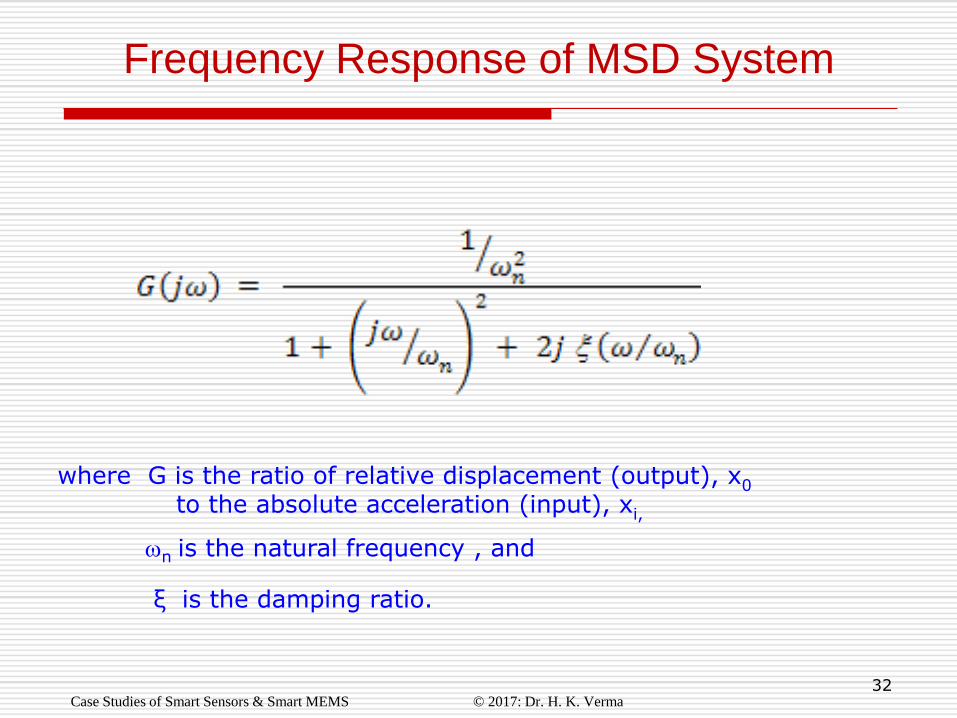
Frequency Response of MSD System
where G is the ratio of relative displacement (output), x0 to the absolute acceleration (input), xi,
ξ is the damping ratio.
n is the natural frequency , and
Case Studies of Smart Sensors & Smart MEMS © 2017: Dr. H. K. Verma
33
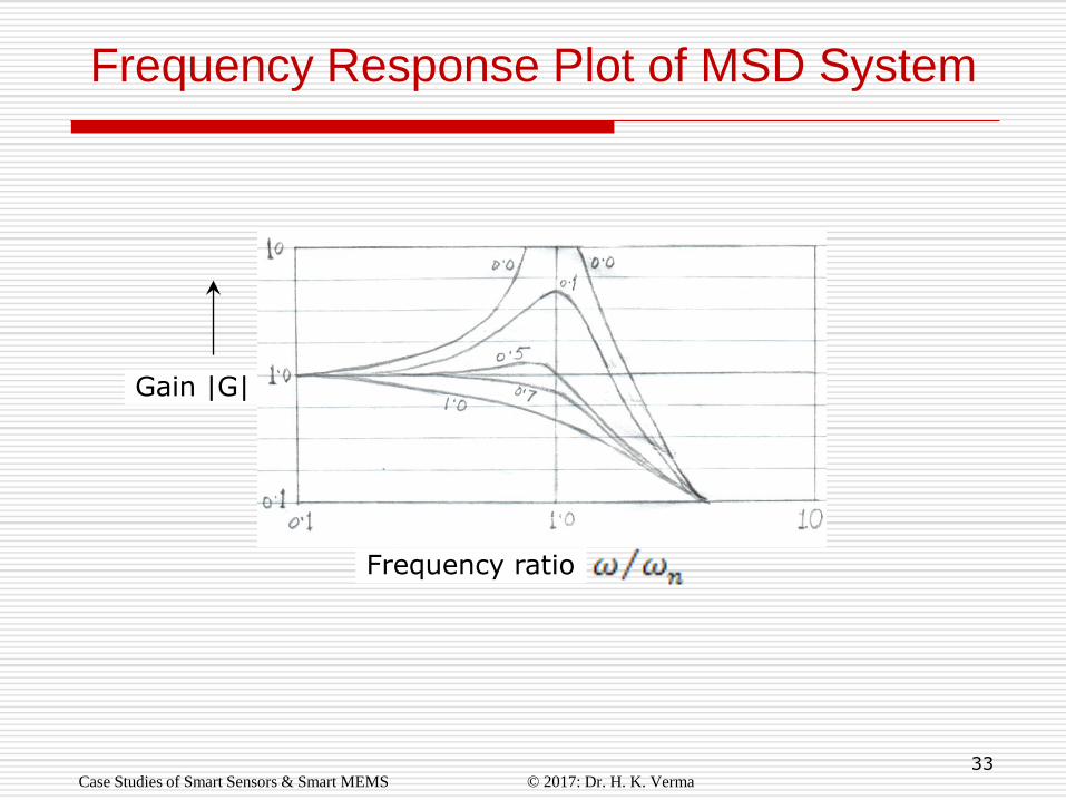
Frequency Response Plot of MSD System
Gain |G|
Frequency ratio
Case Studies of Smart Sensors & Smart MEMS © 2017: Dr. H. K. Verma
34
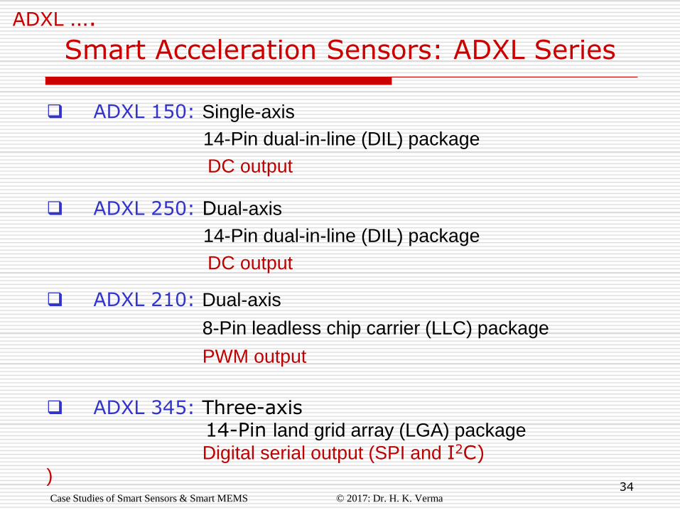
ADXL 150: Single-axis
14-Pin dual-in-line (DIL) package
DC output
ADXL 250: Dual-axis
14-Pin dual-in-line (DIL) package
DC output
ADXL 210: Dual-axis
8-Pin leadless chip carrier (LLC) package
PWM output
ADXL 345: Three-axis 14-Pin land grid array (LGA) package
Digital serial output (SPI and I2C) )
Smart Acceleration Sensors: ADXL Series
ADXL ….
Case Studies of Smart Sensors & Smart MEMS © 2017: Dr. H. K. Verma
35
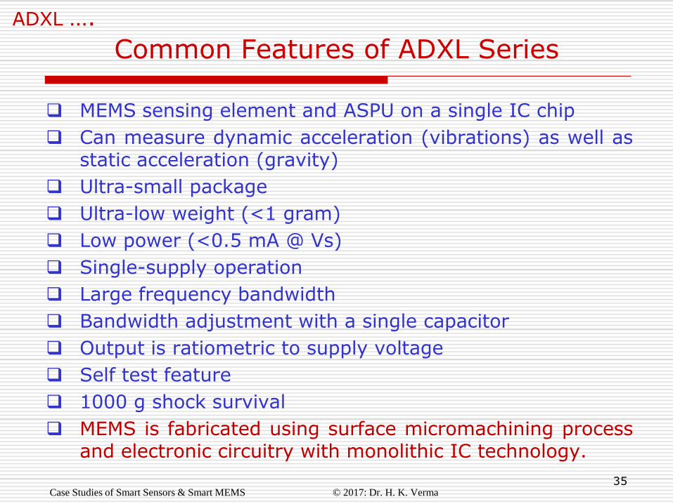
Common Features of ADXL Series
ADXL ….
MEMS sensing element and ASPU on a single IC chip
Can measure dynamic acceleration (vibrations) as well as static acceleration (gravity)
Ultra-small package
Ultra-low weight (<1 gram)
Low power (<0.5 mA @ Vs)
Single-supply operation
Large frequency bandwidth
Bandwidth adjustment with a single capacitor
Output is ratiometric to supply voltage
Self test feature
1000 g shock survival
MEMS is fabricated using surface micromachining process and electronic circuitry with monolithic IC technology.
Case Studies of Smart Sensors & Smart MEMS © 2017: Dr. H. K. Verma
36
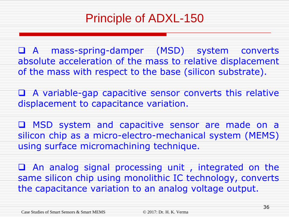
A mass-spring-damper (MSD) system converts absolute acceleration of the mass to relative displacement of the mass with respect to the base (silicon substrate). A variable-gap capacitive sensor converts this relative displacement to capacitance variation. MSD system and capacitive sensor are made on a silicon chip as a micro-electro-mechanical system (MEMS) using surface micromachining technique.
An analog signal processing unit , integrated on the same silicon chip using monolithic IC technology, converts the capacitance variation to an analog voltage output.
Principle of ADXL-150
Case Studies of Smart Sensors & Smart MEMS © 2017: Dr. H. K. Verma
37
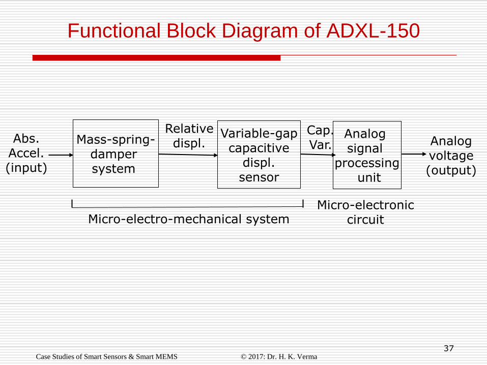
Functional Block Diagram of ADXL-150
Case Studies of Smart Sensors & Smart MEMS © 2017: Dr. H. K. Verma
Mass-spring- damper system
Analog voltage (output)
Variable-gap capacitive
displ. sensor
Relative displ. Abs.
Accel. (input)
Analog signal
processing unit
Cap. Var.
Micro-electro-mechanical system Micro-electronic
circuit
38
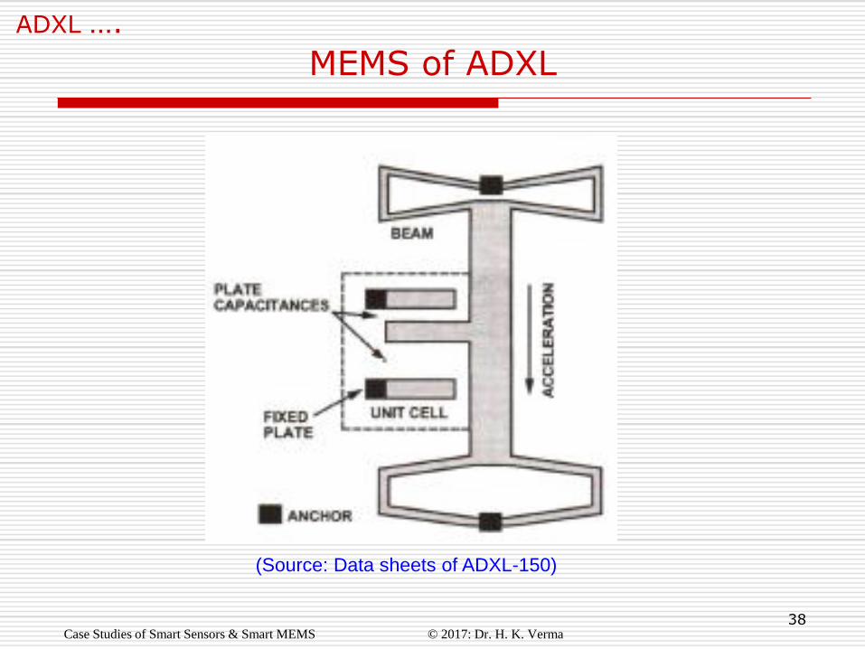
MEMS of ADXL
ADXL ….
(Source: Data sheets of ADXL-150)
Case Studies of Smart Sensors & Smart MEMS © 2017: Dr. H. K. Verma
39
Details of MEMS of ADXL
ADXL ….
Primary and secondary sensing elements are fabricated as a micro-electro-mechanical system (MEMS) using a proprietary surface micromachining process.
Made by depositing poly-silicon on a sacrificial oxide layer that is then etched away leaving behind the suspended primary sensing element.
Secondary sensing element has several capacitance cells for relative displacement of the mass (beam) w.r.t. the base (silicon substrate).
MEMS also has several capacitance cells for electro-statically forcing the beam during self test.
During self-test a force equivalent to 20% of full-scale acceleration acts on the beam and a proportional voltage- change appears on the output pin.
Case Studies of Smart Sensors & Smart MEMS © 2017: Dr. H. K. Verma
40
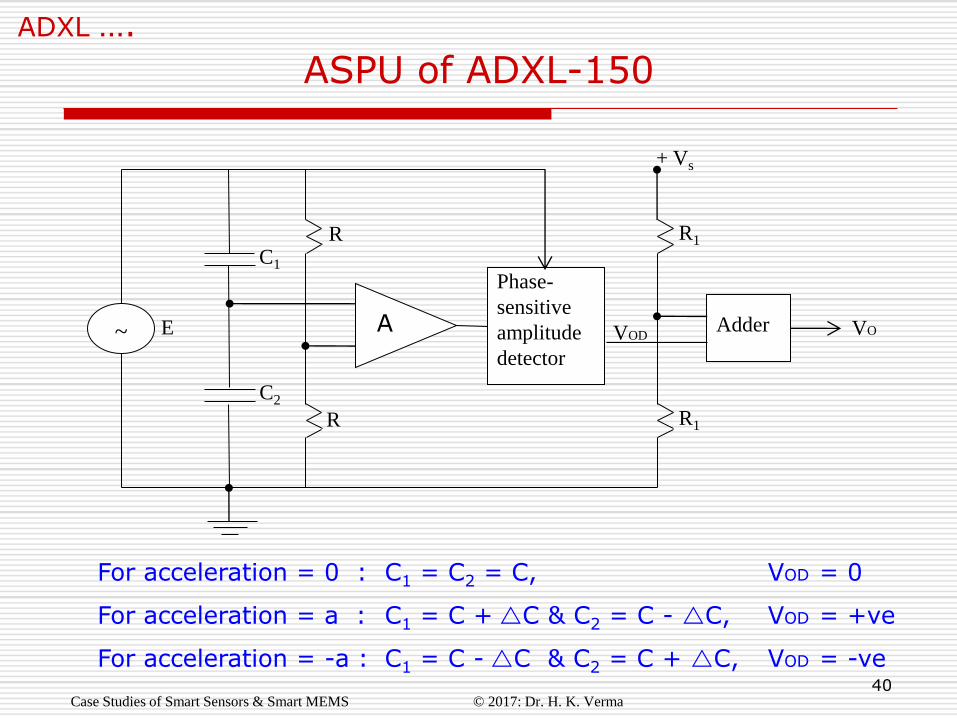
ASPU of ADXL-150
ADXL ….
Phase-
sensitive
amplitude
detector ~
Adder
C1
C2
R
R R1
R1
+ Vs
E
For acceleration = 0 : C1 = C2 = C, VOD = 0
For acceleration = a : C1 = C +C & C2 = C - C, VOD = +ve
For acceleration = -a : C1 = C -C & C2 = C + C, VOD = -ve
A VO
Case Studies of Smart Sensors & Smart MEMS © 2017: Dr. H. K. Verma
VOD
41
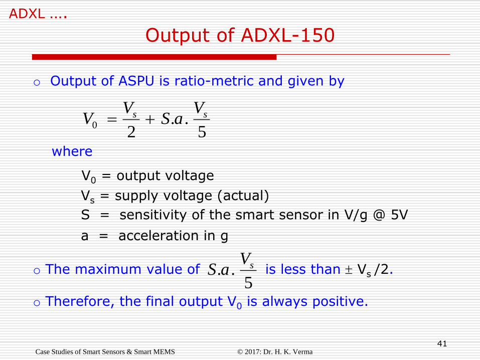
Output of ADXL-150
ADXL ….
5..
20
ss VaS
VV
o Output of ASPU is ratio-metric and given by
where
V0 = output voltage
Vs = supply voltage (actual)
S = sensitivity of the smart sensor in V/g @ 5V
a = acceleration in g
o The maximum value of is less than Vs /2. o Therefore, the final output V0 is always positive.
5.. sV
aS
Case Studies of Smart Sensors & Smart MEMS © 2017: Dr. H. K. Verma
42
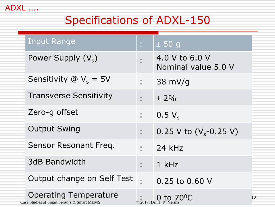
Specifications of ADXL-150
ADXL ….
Input Range : 50 g
Power Supply (Vs) : 4.0 V to 6.0 V Nominal value 5.0 V
Sensitivity @ Vs = 5V : 38 mV/g
Transverse Sensitivity : 2%
Zero-g offset : 0.5 Vs
Output Swing : 0.25 V to (Vs-0.25 V)
Sensor Resonant Freq. : 24 kHz
3dB Bandwidth : 1 kHz
Output change on Self Test : 0.25 to 0.60 V
Operating Temperature : 0 to 700C Case Studies of Smart Sensors & Smart MEMS © 2017: Dr. H. K. Verma
43
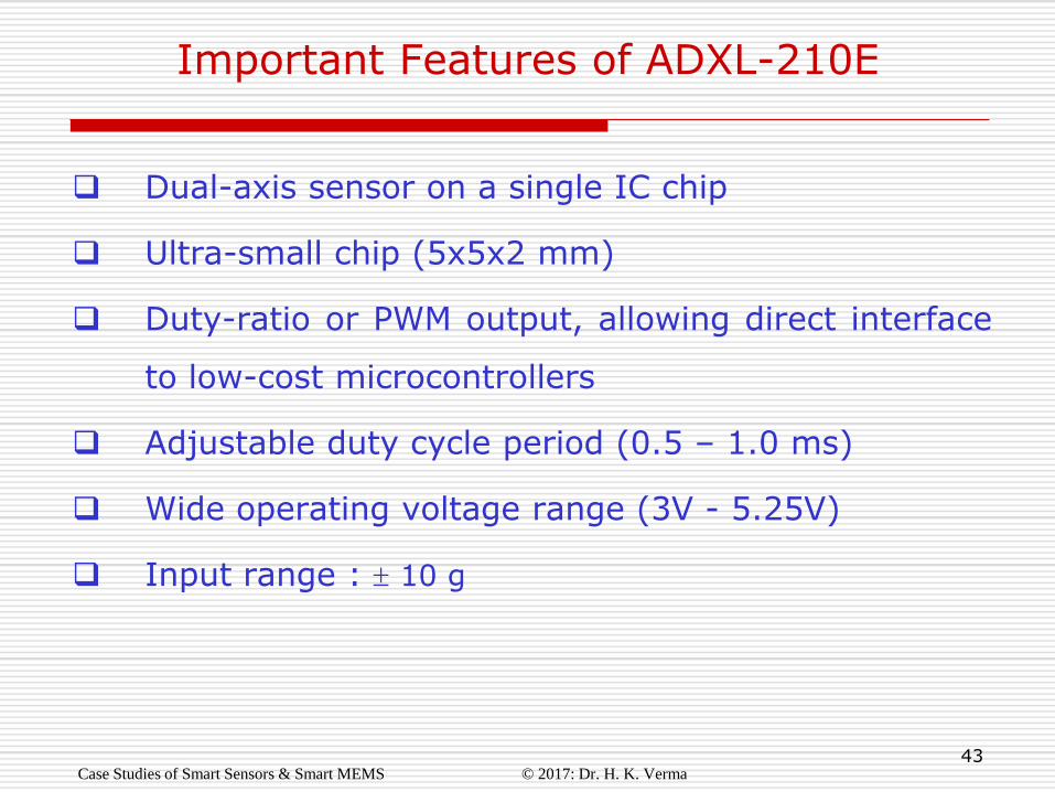
Important Features of ADXL-210E
Dual-axis sensor on a single IC chip
Ultra-small chip (5x5x2 mm)
Duty-ratio or PWM output, allowing direct interface
to low-cost microcontrollers
Adjustable duty cycle period (0.5 – 1.0 ms)
Wide operating voltage range (3V - 5.25V)
Input range : 10 g
Case Studies of Smart Sensors & Smart MEMS © 2017: Dr. H. K. Verma
44
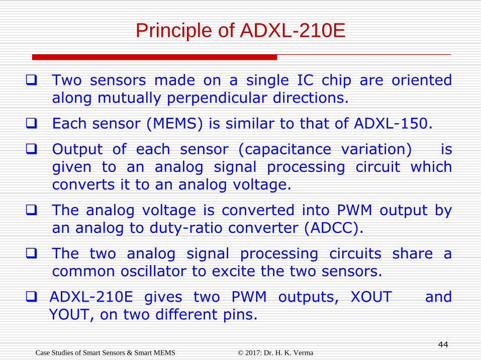
Two sensors made on a single IC chip are oriented along mutually perpendicular directions.
Each sensor (MEMS) is similar to that of ADXL-150.
Output of each sensor (capacitance variation) is given to an analog signal processing circuit which converts it to an analog voltage.
The analog voltage is converted into PWM output by an analog to duty-ratio converter (ADCC).
The two analog signal processing circuits share a common oscillator to excite the two sensors.
ADXL-210E gives two PWM outputs, XOUT and YOUT, on two different pins.
Principle of ADXL-210E
Case Studies of Smart Sensors & Smart MEMS © 2017: Dr. H. K. Verma
45
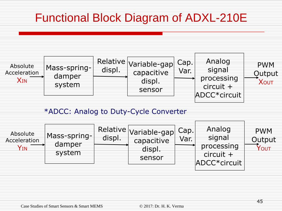
Functional Block Diagram of ADXL-210E
Case Studies of Smart Sensors & Smart MEMS © 2017: Dr. H. K. Verma
Mass-spring- damper system
PWM Output XOUT
Variable-gap capacitive
displ. sensor
Relative displ.
Absolute Acceleration
XIN
Analog signal
processing circuit +
ADCC*circuit
Cap. Var.
Mass-spring- damper system
PWM Output
YOUT
Variable-gap capacitive
displ. sensor
Relative displ.
Absolute Acceleration
YIN
Cap. Var.
Analog signal
processing circuit +
ADCC*circuit
*ADCC: Analog to Duty-Cycle Converter
46
Important Features of ADXL-345
Three-axis sensor on a single IC chip
Ultra-small and thin package (3x5x1 mm)
Digital serial output: SPI (3 & 4 wire) and I2C
13-bit resolution
Wide operating voltage range (2.0V – 3.6V)
Input range: 16 g
Case Studies of Smart Sensors & Smart MEMS © 2017: Dr. H. K. Verma
47
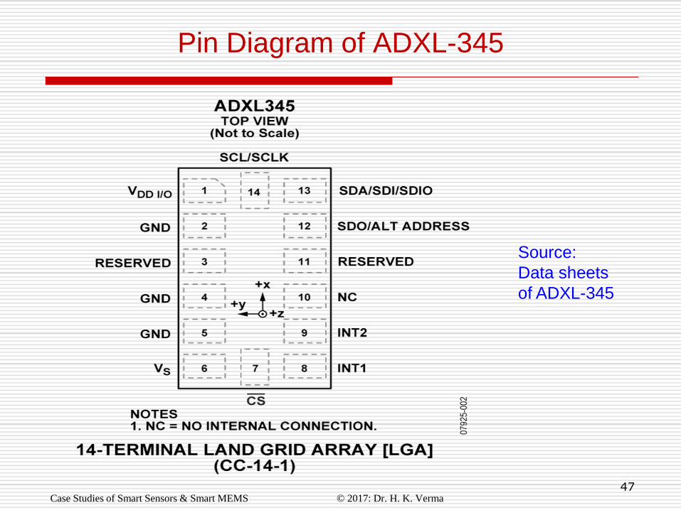
Pin Diagram of ADXL-345
Case Studies of Smart Sensors & Smart MEMS © 2017: Dr. H. K. Verma
Source:
Data sheets
of ADXL-345
48
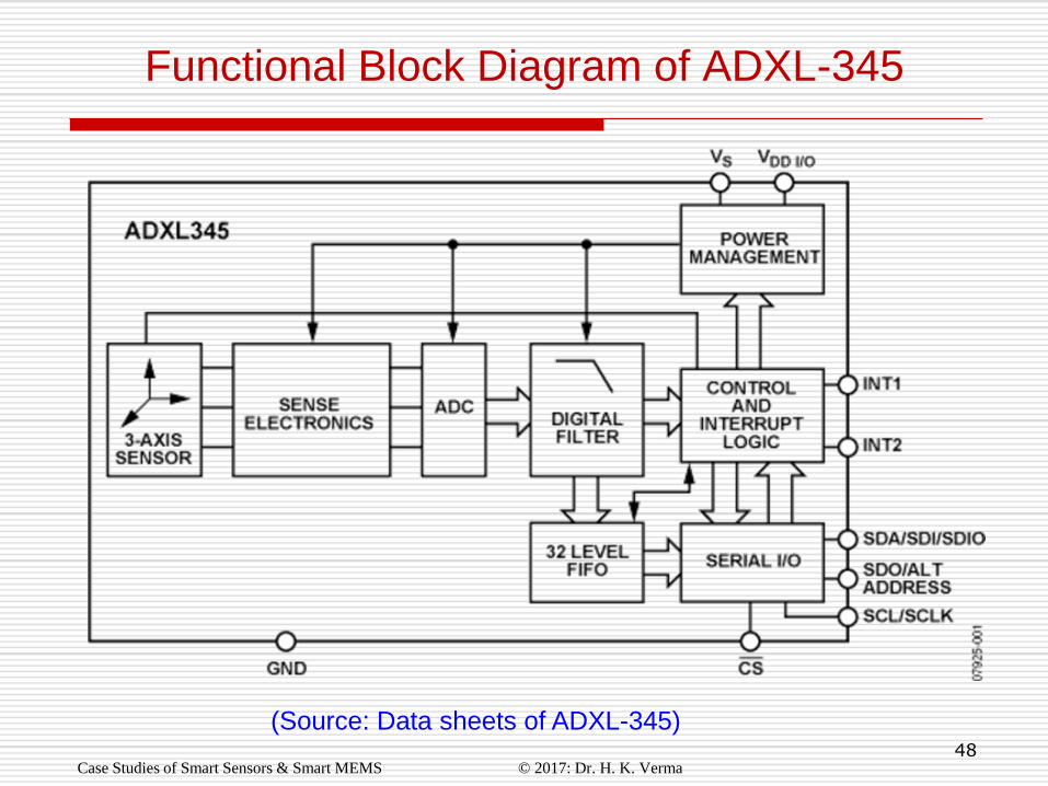
Functional Block Diagram of ADXL-345
Case Studies of Smart Sensors & Smart MEMS © 2017: Dr. H. K. Verma
(Source: Data sheets of ADXL-345)

49
Case Study # 5
Smart Pressure Sensor
or
Integrated Silicon Pressure Sensor
Manufacturer: Freescale Semiconductor Inc.
Website: www.freescale.com
Case Studies of Smart Sensors & Smart MEMS © 2017: Dr. H. K. Verma
50
MPX5700.…….
Types of Pressure and Pressure Sensor
Case Studies of Smart Sensors & Smart MEMS © 2017: Dr. H. K. Verma
Types of Pressure
Differential pressure
Gauge pressure
Absolute pressure
Types of Pressure Sensor
Diaphragm with strain-gauges
Vibrating diaphragm
Piezoelectric

51
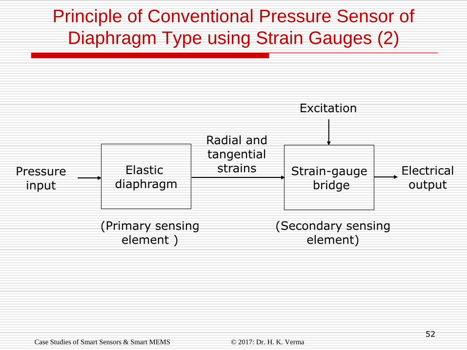
Principle of Conventional Pressure Sensor of
Diaphragm Type using Strain Gauges (1)
Case Studies of Smart Sensors & Smart MEMS © 2017: Dr. H. K. Verma
An elastic diaphragm, acting as primary sensing element, senses the pressure input and converts it into strains.
Radial stress and strain are positive maximum at the periphery of the diaphragm
So two strain gauges are placed along radial directions near the periphery of the diaphragm
Tangential stress and strain are negative maximum at the centre of the diaphragm
So two more strain gauges are placed along tangential directions near the centre of the diaphragm
The four strain gauges are appropriately connected in a full bridge configuration
This strain gauge bridge acts as secondary sensing element.
52
Principle of Conventional Pressure Sensor of
Diaphragm Type using Strain Gauges (2)
Case Studies of Smart Sensors & Smart MEMS © 2017: Dr. H. K. Verma
Elastic diaphragm
Electrical output
(Primary sensing element )
(Secondary sensing element)
Strain-gauge bridge
Radial and tangential
strains Pressure input
Excitation
53
MPX5700 ….
Monolithic silicon pressure sensor
Diaphragm based piezo-resistive sensor
High-level analog output signal
Combines micromachining, bipolar integrated-
circuit and thin-film metallization techniques
Available for absolute, differential and gauge
pressure measurements
Salient Features of MPX5700
Case Studies of Smart Sensors & Smart MEMS © 2017: Dr. H. K. Verma
54
MPX5700 ….
MPX5700A
Smart absolute pressure sensor Has single pressure port
MPX5700D
Smart differential pressure sensor Has two pressure ports
MPX5700G
Smart gauge pressure sensor Has single pressure port With an opening to expose other side of diaphragm
to atmosphere.
Variants of MPX5700
Case Studies of Smart Sensors & Smart MEMS © 2017: Dr. H. K. Verma
55
MPX5700.…….
Principle of MPX5700
Case Studies of Smart Sensors & Smart MEMS © 2017: Dr. H. K. Verma
A silicon diaphragm, serving as primary sensing element,
converts pressure into tangential and radial strains.
Strains are sensed by four piezo-resistive strain gauges
connected as a full whetstone bridge, thus serving as
secondary sensing element.
The bridge output is amplified by a 2-stage amplifier.
The amplified output signal is 0-4.7V @5.0V supply.
56
MPX5700.…….
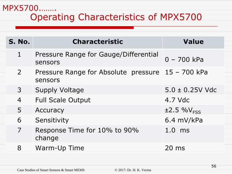
Operating Characteristics of MPX5700
Case Studies of Smart Sensors & Smart MEMS © 2017: Dr. H. K. Verma
…
S. No. Characteristic Value
1 Pressure Range for Gauge/Differential sensors
0 – 700 kPa
2 Pressure Range for Absolute pressure sensors
15 – 700 kPa
3 Supply Voltage 5.0 ± 0.25V Vdc
4 Full Scale Output 4.7 Vdc
5 Accuracy ±2.5 %VFSS
6 Sensitivity 6.4 mV/kPa
7 Response Time for 10% to 90% change
1.0 ms
8 Warm-Up Time 20 ms
57
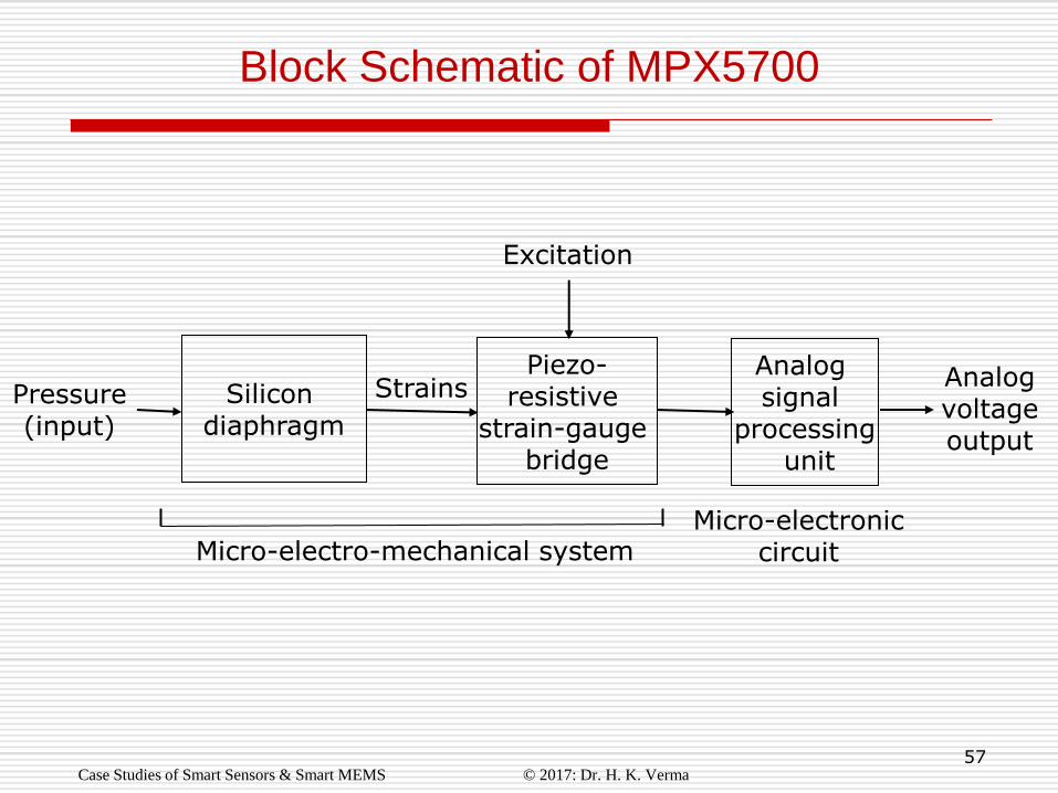
Block Schematic of MPX5700
Case Studies of Smart Sensors & Smart MEMS © 2017: Dr. H. K. Verma
Silicon diaphragm
Analog voltage output
Piezo- resistive
strain-gauge bridge
Strains Pressure (input)
Analog signal
processing unit
Micro-electro-mechanical system Micro-electronic
circuit
Excitation
58
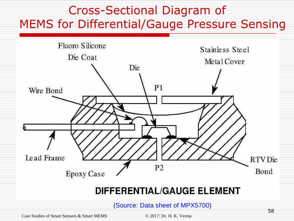
Cross-Sectional Diagram of MEMS for Differential/Gauge Pressure Sensing
Case Studies of Smart Sensors & Smart MEMS © 2017: Dr. H. K. Verma
(Source: Data sheet of MPX5700)

59
Cross-Sectional Diagram of MEMS for Absolute Pressure Sensing
Case Studies of Smart Sensors & Smart MEMS © 2017: Dr. H. K. Verma
(Source: Data sheet of MPX5700)

60
MPX5700 ….
PIN 1: VOUT PIN 2: GROUND PIN 3: VS
PIN 4: NC PIN 5: NC PIN 6: NC
Packages and Pins
Case Studies of Smart Sensors & Smart MEMS © 2017: Dr. H. K. Verma
(Source: Data sheet of MPX5700)