Case Histories of Differnet Seepage Problems for Nine ... · Case Histories of Different Seepage...
20
SECTION 4 Tailings and Waste Disposal-Seepage, Contamination, Regulations, and Control ABSTRACT 36 Case Histories of Different Seepage Problems for Nine Tailings Dams by K. E. Robinson, Partner, Dames & Moore, North Vancouver, British Columbia, Canada, and G. C. Toland, Partner, Dames & Moore, Salt Lake City, Utah, USA Seepage, oversteepened slopes, earthquakes, soft foundations, and pond operations are major design consider- ations for tailings ponds. However, of the numerous tail- ings investigations undertaken by our firm, control of seepage has been, by far, the most significant considera- tion. This paper discusses nine case histories of projects where seepage was, or could have been, a problem. There is an obvious divergence of interests in the design of tailings dams. The requirements for control of pollutants in water courses and groundwater aquifers suggest designs with impervious dams and impoundment reservoirs. Conversely, drainage blankets, and/or pervious foundations and embankments improve stability and permit construction of the most economical structures. This paper discusses projects that include a combin- ation of bvo construction methods - relatively impervious dams constructed using imported materials and relatively pervious "upstream construction" tailings dams, and two foundation types - relatively pervious and relatively impervious. Case histories include some that represent unusual conditions and others that represent the more general problems facing dam designers in the control of seepage. NINE CASE HISTORIES OF SEEPAGE PROBLEMS 781
Transcript of Case Histories of Differnet Seepage Problems for Nine ... · Case Histories of Different Seepage...

SECTION 4 Tailings and Waste Disposal-Seepage, Contamination, Regulations, and Control
ABSTRACT
36 Case Histories of Different Seepage
Problems for Nine Tailings Dams by K. E. Robinson, Partner,
Dames & Moore, North Vancouver, British Columbia, Canada,
and G. C. Toland, Partner, Dames & Moore,
Salt Lake City, Utah, USA
Seepage, oversteepened slopes, earthquakes, soft foundations, and pond operations are major design considerations for tailings ponds. However, of the numerous tailings investigations undertaken by our firm, control of seepage has been, by far, the most significant consideration. This paper discusses nine case histories of projects where seepage was, or could have been, a problem.
There is an obvious divergence of interests in the design of tailings dams. The requirements for control of pollutants in water courses and groundwater aquifers suggest designs with impervious dams and impoundment reservoirs. Conversely, drainage blankets, and/or pervious foundations and embankments improve stability and permit construction of the most economical structures.
This paper discusses projects that include a combination of bvo construction methods - relatively impervious dams constructed using imported materials and relatively pervious "upstream construction" tailings dams, and two foundation types - relatively pervious and relatively impervious. Case histories include some that represent unusual conditions and others that represent the more general problems facing dam designers in the control of seepage.
NINE CASE HISTORIES OF SEEPAGE PROBLEMS 781
INTRODUCTION
Tailings disposal problems have faced the mining engineer for many years. Historically the easiest and most economical solution was to discharge tailings slurry by gravity to the nearest body of water and let nature take care of the disposal problem. However, as communities and farming activities have encroached on mining areas, and fishing industries and interested individuals have applied pressure to government regulatory bodies, the need for properly engineered tailings disposal areas has become apparent. There are many factors that influence the final dam design utilized at a given site such as: topography, geology and foundation soils, tailings properties, method of deposition of slurry, hydrology, alternate use for the impoundment area for water storage or evaporation, availability of construction materials, time constraints, monitoring requirements, costs, stability, seepage limitations and reclamation. All these factors combine to place specific restrictions or boundary conditions on the designers ability to develop a cost effective structure.
Generally the item that affects the design of the impoundment facilities the most is the impact of seepage on stability and pollution control considerations. This paper discusses nine specific projects where seepage was a major factor in the design and/or remedial treatment was required.
It is unfortunately apparent in these case histories that what is good for stability is usually bad for contamination and vice versa. In some of the examples it is apparent that emphasizing one at the expense of the other has caused specific problems.
TYPES OF DAMS AND FOUNDATION CONDITIONS
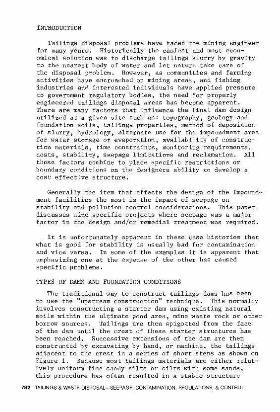
The traditional way to construct tailings dams has been to use the "upstream construction" technique. This normally involves constructing a starter dam using existing natural soils within the ultimate pond area, mine waste rock or other borrow sources. Tailings are then spigotted from the face of the dam until the crest of these starter structures has been reached. Successive extensions of the dam are then constructed by excavating by hand, or machine, the tailings ad1acent to the crest in a series of short steps as shown on Figure 1. Because most tailings materials are either relatively uniform fine sandy silts or silts with some sands, this procedure has often resulted in a stable structure
782 TAILINGS & WASTE DISPOSAL-SEEPAGE, CONTAMINATION, REGULATIONS, & CONTROL

POND
SLIMES
BEACH SEEPAGE WATER LINE
UPSTREAM CONSTRUCTION WITH TA Ill NG S
FIGURE I
because of the natural segregation of sandier materials near the face of the dam and progressively finer materials away from the dam until a "slimes" zone has been reached in the vicinity of the water pond. However, this type of structure can cause stability problems if: 1) the starter dam is constructed using relatively impervious material so that the phreatic surface rises to the outer face of the structure; 2) slimes pockets are permitted to form close to the crest of the dam so that seepage emerges in perched zones up the extending slope; 3) flood conditions combine with slurry deposition to result in a significantly high phreatic surface; or 4) significant earthquake loading results in liquefaction or high stresses in the tailings backfill. This paper discusses five projects where "upstream construction" has been used to raise tailings dams over both pervious and impervious foundations.
Pervious foundations are those that have a higheE4permeabili ty than the tailings backfill - greater than 10 centimeters per second. These foundations are most conducive to dam stability as they provide a continuous drainage blanket under the tailings backfill. Impervious foundations, where the permeability is less than the tailings, are most suitable where seepage control is required. However, for this type of foundation more care is required in designing and constructing the dam to ensure overall safety.
Increasing µressure from society to reduce pollution of streams and groundwater aquifers, particularly from radioactive wastes has resulted in the need to prevent seepage
NINE CASE HISTORIES OF SEEPAGE PROBLEMS 783

from some tailings impoundment facilities. Because requirements for milling activities may result in a need to store water in the tailings pond for recirculation or evaporation purposes, it may be more economical to discharge total tailings at high elevation against a hillside and have slimes and water accumulate at the dam face. Under these conditions it is necessary to construct relatively impervious dams with imported materials using "downstream construction" techniques. This type of construction is illustrated on Figure 2 which shows a total dam completed in one construction phase, or a staged structure with sloping upstream section of relatively impervious material. Four projects where impervious dams have been placed over impervious foundations are discussed
FREE WATER} SEEPAGE WATER LINE
MATERIAL
1--__.,;,..--IMPERMEABLE CORE
SLIMES
DRAIN BLANKET
(a ) TOT AL DAM
(b) STAGED DAM
DOWNSTREAM CONSTRUCTION WITH IMPORTED MATERIALS
FIGURE 2
784 TAILINGS & WASTE DISPOSAL-SEEPAGE, CONTAMINATION, REGULATIONS, & CONTROL

z z rn 0 )> Cf) rn I
~ 0 ~ rn Cf)
0 ,, Cf) rn rn "j; Gl rn -u ::0 0 aJ r rn s: Cf)
al en
ELEVATION IN FEET 3300
3280
3260
3240
3220
3200
, ,
Original Ground Surface
~ 100- minimum to tdQ• of I-.... ponded water -------11""'
Elov. 3290
.,,..,----- ---- -::::.----- ----------- Propoa1d
TaillnQI Backfill
• Exi1tln9 -Taillno1 Backfill
Phreotlc Surface
FEET
m5o m w ~ ~ ~
PROJECT I TYPICAL DYKE SECTION
FIGURE 3

including two cases where the foundations were not as impervious as had originally been anticipated.
RELATIVELY PERVIOUS FOUNDATIONS
Upstream Construction
Project 1.
This project involved the design of an extension to an abandoned silver tailings irnpoundrnent area in the Coeur d' Alene Valley of Idaho. The existing pond was constructed on limited land area where the southern boundary was defined by a railway and the Coeur d'Alene River and the north and west boundaries were defined by a relatively steep hillside. The irnpoundment covers an area of approximately 1400 by 300 feet. The maximum height of the dam of 45 feet had been developed in three raises between 1967 and 1975 as shown on a typical cross-section, Figure 3. Upstream construction techniques had already been utilized with a resulting relatively steep outer slope. Fortunately the foundation soils below the darn consisted of very pervious sand, gravel and cobbles and the starter dam was constructed of similar materials which were excavated within the impoundment area. Because of the topography, it was desired to raise the darn in three 10 foot lifts to a maximum final height of 75 feet.
Problems associated with the design of the raised embankment included: stability considerations because of the steep existing outer slope, slime pockets near the embankment face, control of the phreatic surface and development of a suitable decant system for the raised sections.
Piezometers installed prior to, and during, our investigations indicated that the phreatic surface was very low within the impoundrnent area and close to the foundation sand and gravel in the vicinity of the perimeter embankment. Standard flow net analyses indicated that the phreatic surf ace should be higher. Fortunately, it was possible to complete a full-scale, insitu, constant head permeability test for a period of about 6 weeks. A pond of water was maintained over about 50 percent of the tailings impoundment area by pumping water at the rate of 450 gallons per minute for about 16 hours per week. By monitoring piezometers it was possible to establish that the predominant seepage path is downward through the tailings backfill and into the permeable foundation gravels. This indicated that there are sandy areas vertically connected throughout the backfill
786 TAILINGS & WASTE DISPOSAL-SEEPAGE, CONTAMINATION, REGULATIONS, & CONTROL

near the embankment face which intersect slimes pockets that could otherwise cause perched water zones. This observation agrees with experience on other projects where granular foundations underlie tailings impoundment facilities.
Based on the field investigation and full scale permeability and laboratory tests, the raised embankment crosssection shown on Figure 3 was designed. This design included excavating a drainage trench through the upper area of the existing tailings to cut through some fairly continuous slimes zones to provide more positive interconnection between sand zones. The overall slope was flattened to 2 horizontal to 1 vertical from the original slope of 1.3 horizontal to 1 vertical. With the drainage provided, a range of phreatic surfaces as shown on Figure 3 is anticipated. Under these conditions the dam will be stable, even under design seismicity which was studied in detail as discussed in a paper by McKee, Robinson and Urlich (1978)*. To determine actual phreatic surfaces and provide for remedial action, if necessary, such as further slope flattening or keeping the pond more than the design requirement of 100 feet from the crest of the dike at any stage, a series of piezometers have been installed and additional piezometers will be placed during future extensions of the dam. Water level monitoring is vital to the design concepts discussed above, and requires specific mine action.
Project 2.
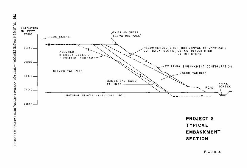
This project involved a tungsten disposal area near Bishop, California. Tailings have been discharged against a relatively steep talus-covered valley wall of Pine Creek Canyon. A series of four tailings ponds have been established over a 4000 by 900 foot area. The ponds are confined by Pine Creek on one side and the talus slopes on the other. The four ponds are constructed adjacent to one another in a stair-step configuration. The maximum embankment heights are in the order of 200 feet with side slopes developed by "upstream construction" methods of between 1. 2 and 1. 8 horizontal to 1.0 vertical, as indicated on the typical section shown on Figure 4. A unique feature of this project is the high perimeter embankment which was recently subjected to significant earthquake accelerations, with no apparent signs of distress,
*References are included at the end of the text.
NINE CASE HISTORIES OF SEEPAGE PROBLEMS 787
iii a>
~ r z Gl en Qo
~ ~ m g en -u 0 en > r I
en m m "i! Gl jTI
() 0 z );! ;;:: z ~ cs _z ::IJ m Gl c r
~ cs z 5fl Qo
() 0 z -I ::IJ 0 r
ELEVATION IN FEET
7300
7250
7200 _,
71 5 0
7100_
7050
TALUS SLOPE
-, EXISTING CREST ELEVATION 7266'
ASSUMED -,~ ..... A'' HIGHEST LEVEL OF --- ---- -___ PHREATIC SURFACE__.,;;>-.,,
SLIMES TAILINGS
RECOMMENDED 2 TO I (HORIZONTAL TO VERTICAL) CUT BACK SLOPE, USING 15FOOT HIGH
1.5 TO I STEPS
EMBANKMENT CONFIGURATION
SAND TAILINGS
SLIMES AND TAILINGS--------
NATURAL GLACIAL-ALLUVIAL SO!L
PROJECT 2
TYPICAL
EMBANKMENT
SECTION
FIGURE 4

Foundation conditions below the tailings ponds consist of a combination of talus from the adjacent mountain slopes and finer grained, glacio-alluvial soils. The permeability of the foundation soils ranges from moderately low to high. However, the back boundary of all the ponds is formed by highly permeable talus which provides direct drainage into the more highly permeable foundation soils, as indicated schematically on the valley profile shown on Figure 5. Decanting of liquids from the pond surfaces has not been required because of the permeable nature of the talus backing. In Pond 3 where the talus tends to be somewhat less permeable, infiltration wells have been installed to provide decanting directly into more coarse talus at lower elevations.
With this highly permeable zone at the back of the impoundments, it was assumed that the phreatic surface was very low within the tailings near the embankment face and that this was the reason for the long term stable condition of the embankments. However, high water level readings in old piezometers resulted in our recent investigation. The purpose was to determine if the phreatic surface was high and, if it was, what remedial action to take, if any. Fortunately, our investigation, which included the installation of a number of isolated piezometers in each boring, detected only nominal perched water levels in some areas where slimes had been allowed to accumulate near the face of the dam. Overall stability was not adversely affected.
Of special interest during our investigation was an earthquake about 12 miles from the site of Magnitude 5.7 on the
ALLUVIUM
PROJECT 2 OF VALLEY PROFILE Fl GURE 5
NINE CASE HISTORIES OF SEEPAGE PROBLEMS 789

Richter scale which caused estimated accelerations at the base of the embankments of about 0.12g with peak accelerations approaching 0.2g. Drilling was in progress at the time of the quake and our inspector observed numerous rockfalls and minor slides on the adjacent hillsides. The drill rig was shaking so violently that the drill rod bent in the hole and a just recovered sample partially liquified. How7 ever, the embankment suffered no distress and the only signs of disturbance were observed in areas adjacent to ponded water back from the face, where settlement indicated minor near surface liquefaction.
Back stability analyses of the slopes using the actual earthquake loading conditions confirmed that the phreatic surface had to be extremely low, as indicated on Figure 4, and there was significant apparent cohesion in the sand zone near the face of the dam. Tailings disposal by spigotting from successive upstream construction lifts resulted in a series of three zones of tailings including an outer sand zone, an intermediate silty sand to sandy silt zone, and an interior slime zone as indicated on Figure 4.
This project indicates that under extremely favorable site conditions a very economical structure can be utilized to store tailings to relatively high final elevations. However, our investigations did indicate that long term stability should be improved slightly by flattening the overall slope as shown on Figure 4 to 2 horizontal to 1 vertical. This flattening can be completed efficiently and economically by utilizing the stripped material to raise successive lifts of Pond 4 which is presently only 30 feet high.
Impervious Dams
Project 3.
This tailings disposal project located in Europe was designed as an impervious dam founded on an impervious foundation. However, because of unusual conditions in the immediate vicinity of the dam, problems developed which required remedial treatment. It was intended that the dam act as a water storage reservoir because of the need to recycle as much water to the mill as possible. Because of limited available borrow materials, it was necessary to construct the 80 foot starter dam using rockfill with a thin concrete liner on the upstream face to provide an impervious boundary. Tailings would be discharged up the valley from the dam to form a sloping beach front with slimes accumulat-
790 TAILINGS & WASTE DISPOSAL-SEEPAGE, CONTAMINATION, REGULATIONS, & CONTROL

ing near the dam and a water pond adjacent to the structure. Foundations under the reservoir consisted of relatively impervious slates which have almost vertical bedding. The dam itself is founded on a vertically bedded Karstic limestone formation which forms the most resistant part of the valley. The strike of the formation is parallel to the axis of the dam and the limestone extends just past the upstream toe. The Karstic nature of the limestone was recognized and a grout blanket was placed over the exposed limestone in the reservoir area.
During initial filling of the reservoir sinkholes developed on a number of separate occasions which resulted in draining of the reservoir, subsequent repair by placing mine waste and debris in the exposed sinkhole and refilling of the reservoir. After the last sinkhole developed, an investigation was completed to establish the extent and degree of sinkholes that could exist in addition to those already observed, and to develop remedial measures to prevent further sinkholes from developing. This would be particularly critical during future extensions of the dam which would raise it to an ultimate height of 200 feet.
The area where the sinkholes were observed was immediately upstream of the toe of the concrete face in the center of the valley. At this location it had been extremely difficult to completely strip and clean the fine grained soils at the base of the valley during construction because of water and available space. During the subsequent investigation a number of interconnected sinkholes were uncovered when this area was carefully stripped. In addition, very extensive caverns were detected in the limestone formation in the left abutment near the crest of the ultimate dam.
Two solutions were proposed to solve the problem and permit tailings disposal as quickly as possible. One included deposition of tailings from the dam face to develop a sand zone adjacent to the dam. This would be combined with a granular drainage blanket over the Karstic limestone formation. This approch would keep the ponded water away from potential future sinkholes and provide a filter above the limestone. The second alternative, which was ultimately chosen, consisted of placing a ten-foot thick zone of mine waste over the limestone on the assumption that this material would bridge and plug potential sinkholes that could develop during future operations. Both solutions required extremely careful cleaning of all soil over the unprotected limestone and plugging of any openings in the limestone with a combin-
NINE CASE HISTORIES OF SEEPAGE PROBLEMS 791
ation of mine waste and concrete.
Project 4.
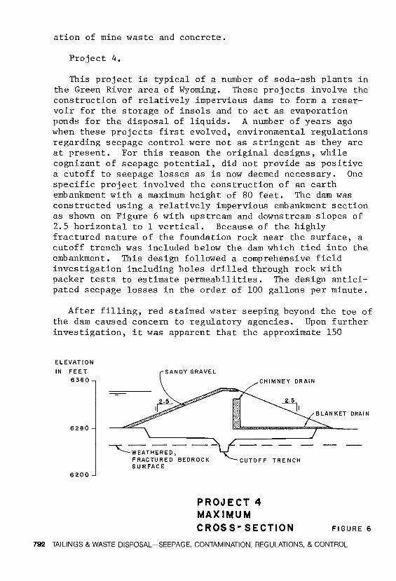
This project is typical of a number of soda-ash plants in the Green River area of Wyoming. These projects involve the construction of relatively impervious dams to form a reservoir for the storage of insols and to act as evaporation ponds for the disposal of liquids. A number of years ago when these projects first evolved, environmental regulations regarding seepage control were not as stringent as they are at present. For this reason the original designs, while cognizant of seepage potential, did not provide as positive a cutoff to seepage losses as is now deemed necessary. One specific project involved the construction of an earth embankment with a maximum height of 80 feet. The dam was constructed using a relatively impervious embankment section as shown on Figure 6 with upstream and downstream slopes of 2.5 horizontal to 1 vertical. Because of the highly fractured nature of the foundation rock near the surface, a cutoff trench was included below the dam which tied into the embankment. This design followed a comprehensive field investigation including holes drilled through rock with packer tests to estimate permeabilities. The design anticipated seepage losses in the order of 100 gallons per minute.
After filling, red stained water seeping beyond the toe of the dam caused concern to regulatory agencies. Upon further investigation, it was apparent that the approximate 150
ELEVATION
IN FEET
6360
6280
6200
SANDY GRAVEL
~WEAT~D-,FRACTURED BEDROCK SURFACE
CHIMNEY DRAIN
CUTOFF TRENCH
PROJECT 4 MAXIMUM CROSS- SECTION FIGURE 6
792 TAILINGS & WASTE DISPOSAL-SEEPAGE, CONTAMINATION, REGULATIONS, & CONTROL

gallons per minute of observed seepage was indicative of water losses from the reservoir which passes into fractures that extended below the impervious cutoff toward the abutments of the dam. While the total volume of seepage was not exceptional, and was within the limits of reasonable estimates, the effect on environmentalists was significant because of the color and its visual impact.
For this project remedial action was not required because of the existence of an old pond at a lower elevation down valley from the dam under consideration. This dam acts as a secondary evaporation pond with excess water pumped back to the upper pond. However, the significance of minor geologic features such as interconnected fracture zones beneath irnpoundment areas which could extend around abutments or under the main fracture zone, that would be sealed by an impervious cutoff, for these types of darns must be given careful consideration in future projects. It is probable that the best solution would include a small holding pond downstream to collect and return seepage thereby reducing the need for a comprehensive cutoff below the dam which may be next to impossible to provide.
RELATIVELY IMPERVIOUS FOUNDATIONS
Upstream Construction
Project 5.
This project illustrates the potential problems that can develop where upstream construction is utilized under uncontrolled conditions and unusual climatology. This project, located on the western flank of the Rocky Mountain Trench near Kimberley, British Columbia, involved the failure of an iron tailings dike and the subsequent loss of 2 million tons of stored tailings in 1948. Tailings had been deposited for many years utilizing the old historical procedure of raising the embankment by steps using hand mucking procedures and tailings, with spigotting from trestles mounted on the crest of the rising darn section. Details of the structure, height and size are sketchy. However, based on discussions with people involved and our observations, it appears that failure was the direct result of freezing conditions and a high phreatic surface. That particular year snow melt and spring runoff started a few weeks before the failure. However, a later cold spell resulted in extremely low temperatures and refreezing of the face of the dam which probably resulted in
NINE CASE HISTORIES OF SEEPAGE PROBLEMS 793

a raised water surf ace as runoff and seepage water accumulated against the crest of the dam. A slope failure from static seepage conditions probably resulted and caused excessive shear stresses throughout the embankment and adjacent backfill. This apparently resulted in liquefaction of a large mass of tailings which flowed down a valley towards the St. Mary River a few miles away. Fortunately the two work~ men, who were attending the spigots ancl slurry disposal system at the time of the failure, were able to manoeuvre across frozen chunks of soil to the side of the valley as the sliding mass moved downslope.
Foundation conditions under the tailings area where the failure occurred are not known exactly. However, a recently constructed dam downstream from the failure area was placed over renmants of the old iron tailings spill which rested directly on relatively impervious glacial till. It is therefore expected that the foundation materials in the vicinity of the failure are relatively impervious.
For the new embankment system it was possible to construct a 30 foot high starter dam using silica tailings as borrow material after placing an initial 4-foot thick lift of sand and gravel to develop a working pad. Because of the sensitive nature of the saturated tailings foundation materials at the site, it was necessary to construct the first 4-foot lift slowly while frequently monitoring piezometers installed in the foundation tailings. A series of upstream construction lifts will raise the ultimate structure to a total height of 80 feet. The first 2 lifts have already been completed. Because of the sensitivity of the structure to seepage, a nrnnber of piezometers have been installed and monitored on a regular basis. A carefully designed drainage blanket at the base of the starter dam combined with spigotting from the dam crest has kept the phreatic level well within the design requirements discussed in detail in a paper by Robinson (1978).
Project 6.
This project involves a uranium tailings disposal area where upstream construction techniques were used to build an embankment of over 150 feet maximrnn height. The impoundment area, including two separate ponds having a total area of about 50 acres each, is situated above the San Miguel River where riverbank side slopes are in the order of 30 degrees or less. Foundation conditions for the dam consist of
794 TAILINGS & WASTE DISPOSAL-SEEPAGE, CONTAMINATION, REGULATIONS, & CONTROL

relatively impervious, sound sandstone. The 25 foot high starter dam was constructed utilizing sand tailings from a previous disposal area.
The outside face of the dam varies in slope from 1.5 to 3.0 horizontal to 1.0 vertical with the flattest sections at the higher levels of the embankment as shown on Figure 7. The steep lower dam section rests directly on relatively impervious rock, resulting in seepage at the toe of the section and some erosion and degradation. A slide in one section of this lower slope occurred as a result of seepage buildup combined with surface freezing which raised the water level against the steep slope. We investigated the dam and concluded that the factor of safety under steady state seepage conditions was 1.2.
To improve stability and eliminate potential erosion and piping at the toe of the dam, we recommended that a rockfill berm be placed on the downstream face, as shown on Figure 7, and the pond be operated to keep decant water as far from the face as possible. The rock buttress fill has not yet been
ELEVATION
IN FEET
200
IO 0
"'-----TAILINGS
HORIZONTAL DRAIN......__ --
0 BEDROCK
SCALE= !"=100°
--
PROJECT 6
TYPICAL
CROSS-SECTION
RECOMMENDED ROCK FILL BUTTRESS (NOT CONSTRUCTED)
OUTLINE OF DAM
FIGURE 7
NINE CASE HISTORIES OF SEEPAGE PROBLEMS 795

constructed. As an alternative to this remedial treatment, the owner requested a test section of horizontal drains be installed which, if successful, could provide a more economical solution to the seepage problem. Based on the test section, it was apparent that drain spacing would have to be less than 5 feet along the darn which was too expensive an undertaking. The close spacing would be required because of the permeability of the sands of about lo-4 centimeters per second, and the random pockets and layers of slimes that were within the zone requiring drainage. This can be a common problem for darns using "upstream construction" unless spigotting is completed under controlled conditions, with sufficient spigot points to minimize ponding near the crest where slimes would be deposited. The most significant factors affecting this project were the impervious rock foundation and the proximity of the pond to the darn crest.
Project 7.
A number of tailings ponds have been established at a large copper mine in Arizona. The first four ponds were located in small valleys on either side of a ridge so that they eventually combined as the tailings darns were extended to a maximum height of about 200 feet. Because of problems with one of the embankments, a new cross-section was designed for a high darn that is presently being used for tailings disposal.
Bedrock in the area is dacite which is sound where unweathered, but is generally covered by weathered rock and residual soil. This upper zone is a relatively impermeable lo-6 centimeters per second or less. The problem irnpoundrnent area was constructed using a 45 foot high starter darn of weathered dacite - well graded silty sand with gravel. A stationary cyclone was established which directed sands to the darn crest and slimes to the back pond area. Upstream construction was then provided by excavating beach sand and placing it in 6 to 8 foot lifts.
After the total height had exceeded 60 feet during early filling, the cyclone broke down and total tailings were discharged into the back of the pond. This forced the ponded water and slimes to rest against the darn face. This combined with the relatively impervious starter darn, raised the phreatic surface to critical levels and required remedial action. A series of "French" drains were installed along raised sections of the darn to collect near surface seepage and direct it to a collection system. This prevented seepage from emerging at
796 TAILINGS & WASTE DISPOSAL-SEEPAGE, CONTAMINATION, REGULATIONS, & CONTROL

the top of the starter dam. Provisions were then made to spigot total tailings from the dam crest and develop a beach at the face keeping the pond away.
The design of a new tailings disposal area required two starter dams. One dam initially stored sand tailings from a large cyclone while the second one was constructed 2500 feet upstream to store the s·limes,Jovertilow. The 120 foot high main starter dam was constructed with a main downstream shell of broken rock in a 30 foot wide filter zone of minus 3 inch rock, and a 50 foot wide upstream zone of well graded broken conglomerate. A system of internal drains was incorporated into the final design.
Once the storage between the two starter dams was filled with sand, total tailings were discharged from the crest of the main starter dam so that standard upstream lifts could be used to complete the dam to its ultimate height of 630 feet.
With sand tailings stored behind the main starter dam and internal drains, a well designed system was established creating positive drainage and a low phreatic surface. For both the large dam system and the original pond, water level control was aided by establishing a minimum distance between dam crest and ponded water. For the large dam the pond setback varies from 200 feet at the starter dam level to 750 feet at the ultimate crest.
Project 8.
This project is relatively typ.ical of the impact of government regulations on the construction of uranium tailings impoundments. The project is located in Wyoming and required the design of tailings dam embankments 50 feet high over an area of 3000 by 3000 feet. This project went through many stages of design, review and redesign as the regulatory agencies required more stringent controls against seepage loss. It was a case where the designers suggested three alternative methods for controlling seepage and providing a safe structure, and the regulatory authorities eventually insisted on all three procedures being utilized.
The dam is presently being constructed with alluvial sllilty sands and sandy silts with an upstream slope of 3 horizontal to 1 vertical and downstream slopes of 2 horizontal to 1 vertical above and below an intermediate 15 foot wide bench. Soil conditions below the impoundment area consist of low
NINE CASE HISTORIES OF SEEPAGE PROBLEMS 797

permeability, poorly indurated siltstones and sandstones. This material has a measured permeability of lo-5 centimeters per second, and a water table 90 feet below the existing ground surface.
Because of an apparent overreaction to the control of radioactive waste, the owner was forced to include synthetic liners in the embankment and throughout the pond area. In addition the design was changed to require a 50-deep excavation below existing grade so that all tailings would be buried. The 50-foot high dam then forms a retention structure for stored liquids prior to effluent evaporation. Because of liner costs, the owner decided to construct the impoundment area in a grid of four stages so that capital costs could be deferred even though embankment costs would eventually be much higher.
The most serious concern to design consultants is the apparent need for redundant safety features. With the foundation material having such a low permeability and a significant capacity for radionuclide uptake by ion exchange, the need for placing a liner under the total impoundment facility was questioned. Even though the liner was utilized, the regulatory agency require an embankment stability analysis based on full saturation with 18 monitoring piezometers - requirements which are considered to be extremely conservative.
Project 9.
This tailings disposal project, located in the Shirley Basin, Wyoming, also involved uranium tailings. Foundation conditions consist of poorly indurated claystones and sandstones having relatively low permeability. The design included a maximum dam height of 60 feet, upstream and downstream slopes of 2 horizontal to 1 vertical and 2.5 to 1, respectively. The structure was raised in 3 stages with an impervious cut-off trench located at the toe of the first embankment stage. Succeeding stages were built in the downstream direction as shown on Figure 8. The main embankment section was constructed using a relatively low permeability clayey sand.
Of significance for this project was that the design required control of the phreatic surface with a chimney drain. Because it was not possible to find a suitable graded borrow material in the area that would satisfy filter criteria and provide the required drainage, it was necessary to satisfy
798 TAILINGS & WASTE DISPOSAL-SEEPAGE, CONTAMINATION, REGULATIONS, & CONTROL

z z m
§;? en m I
~ 0 ;!;! 8j 0 "Tl en m m
~ GJ m -u :Il 0 CD r m s: en ..... co co
CLAYEY SAND
{INTERMEDIATE DAM)
CYCLONED TAILINGS
PROJECT 9
TYPICAL SECTION
EMBANKMENT HEIGHT GREATER
THAN 30 FEET
ELEVATION IN FEET
7120
7080
7040
7000
FIGURE 8

the authorities that cycloned uranium tailings would be suitable. This was done and the chimney drain was connected to a blanket drain also constructed of cycloned sands. This material provided a stable dam section. Seepage passing through the structure is being collected by ditches just downstream of the toe where it is directed to a sump and pumped back to the reservoir.
Of further interest on this project was the fact that regulatory authorities did not agree on the most suitable method for construction of the dam, One agency requested the use of an all clay structure with no internal drainage system while the other insisted on an internal drainage system similar to that utilized. It is also of interest that monitoring of the pump back water from the collector ditch has shown low concentrations of radionuclides. This has been attributed to the effects of ion exchange in the dam fill and natural foundation materials.
CONCLUSIONS
The case histories discussed in this paper cover a wide variety of embankment and foundation conditions. These projects were chosen because, in some cases, they represent unusual conditions, while in others, they tend to be representative of more general problems facing tailings dam designers in the control of seepage. If pollution control requirements permit, it is most desireable to provide as free draining a structure as possible and use "upstream construction". However, if it is necessary to provide tight controls over seepage losses, and a permeable structure with a pump back system can not be utilized, then extreme care is required in assessing the near surface geological conditions. Seepage problems associated with foundation conditions in the reservoir can have a much more significant impact on the total facilities than a properly designed dam structure used to retain the perimeter of the tailings.
REFERENCES
McKee, B. E., Robinson, K. E., and Urlich, C. M. (May 1978) "Upstream Design for Extension of an Abandoned Tailings Dam" - Tailings Disposal Today, Vol. 2, Miller Freeman Publications.
Robinson, K. E. (1977) "Tailings Dam Constructed on Very Loose, Saturated Sandy Silt" - Canadian Geotechnical Journal; Vol. 14, No. 3.
800 TAILINGS & WASTE DISPOSAL-SEEPAGE, CONTAMINATION, REGULATIONS, & CONTROL