Cascade 3072 Delivery System - Atlas Resell Management 3072 Intallation Guide.pdfCascade 3072...
8
Cascade ® 3072 Delivery System I NSTALLATION G UIDE 86.0128.00 Rev H Getting Started See the section below that applies to your unit. Delivery System Mounted to the Wall . . . . . . . . . . . . . 1 Delivery System Mounted to Preference II 5512 Cabinet . . . . . . . . . . . . . . . . . . . . . . . . . . . . . . . . . . . . . . 4 Delivery System Mounted to Preference Collection 5531/5631 Cabinet (Sink Side) . . . . . . . . . . . . . . . . . . 4 Delivery System Mounted to Preference Collection 5531/5631 Cabinet to Storage or Drawer Side . . . . . 5 Delivery System Mounted to Preference II 5612 Cabinet . . . . . . . . . . . . . . . . . . . . . . . . . . . . . . . . . . . . . . 5 Delivery System Mounted to Preference Collection 5543 Central . . . . . . . . . . . . . . . . . . . . . . . . . . . . . . . . . 6 Recommended Tools • Hex key set • Level • Diagonal cutters • 1/8" drill bit • 3/16" drill bit • Electric drill Figure 1. Cascade 3072 Delivery System Delivery System Mounted to the Wall Select the Backboard Mounting Location The location of the backboard must allow the control head to easily reach the desired working area at the dental chair. WARNING Consult a licensed professional, such as a structural or architectural engineer, for mounting to metal stud or masonry walls. Ensure that all installations conform to local code requirements. Mounting structure must be designed to support a minimum shear load of 100 lb (445 N) and a minimum moment of 112 ft-lb (152 N-m).
Transcript of Cascade 3072 Delivery System - Atlas Resell Management 3072 Intallation Guide.pdfCascade 3072...
Cascade® 3072 Delivery SystemINSTALLATION GUIDE
Getting Started
See the section below that applies to your unit.Delivery System Mounted to the Wall . . . . . . . . . . . . . 1Delivery System Mounted to Preference II 5512 Cabinet . . . . . . . . . . . . . . . . . . . . . . . . . . . . . . . . . . . . . . 4Delivery System Mounted to Preference Collection 5531/5631 Cabinet (Sink Side) . . . . . . . . . . . . . . . . . . 4Delivery System Mounted to Preference Collection 5531/5631 Cabinet to Storage or Drawer Side . . . . . 5Delivery System Mounted to Preference II 5612 Cabinet . . . . . . . . . . . . . . . . . . . . . . . . . . . . . . . . . . . . . . 5Delivery System Mounted to Preference Collection 5543 Central . . . . . . . . . . . . . . . . . . . . . . . . . . . . . . . . . 6
Recommended Tools
• Hex key set
• Level
• Diagonal cutters
• 1/8" drill bit
• 3/16" drill bit
• Electric drill
Figure 1. Cascade 3072 Delivery System
Delivery System Mounted to the Wall
Select the Backboard Mounting LocationThe location of the backboard must allow the control head to easily reach the desired working area at the dental chair.
WARNING Consult a licensed professional, such as a structural or architectural engineer, for mounting to metal stud or masonry walls. Ensure that all installations conform to local code requirements. Mounting structure must be designed to support a minimum shear load of 100 lb (445 N) and a minimum moment of 112 ft-lb (152 N-m).
86.0128.00 Rev H
Cascade 3072 Delivery System Installation Guide
• The maximum extension of the arm is 54" (1372 mm) or 63" (1600 mm) from the mounting surface to the front edge of the control head.
• Maximum vertical travel of the work surface is 18" (457 mm) or 26" (660 mm) respectively.
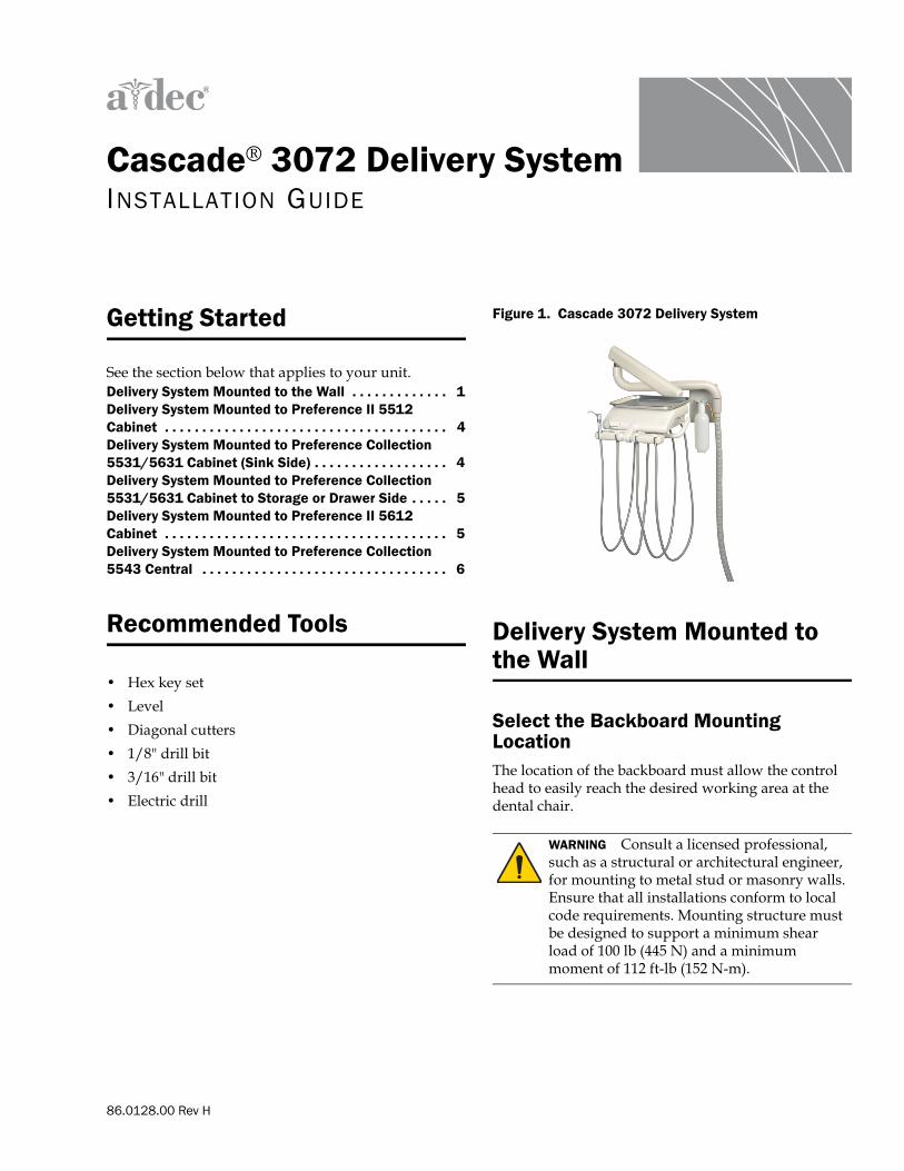
Mount the Backboard1. Hold the backboard template, p/n 85.0049.00,
against the wall in the location selected (see Figure 2). Place a level at the top line of the template to ensure the template is level before marking the mounting holes.
Figure 2. Backboard Template
2. Mark the six mounting holes. Drill a 3/16” (5 mm) diameter hole at these locations.
3. Align the backboard with the mounting holes and secure it in place with the five 2-1/2” (64 mm) long lag bolts from the ship kit. Check to make sure the backboard is level before tightening.
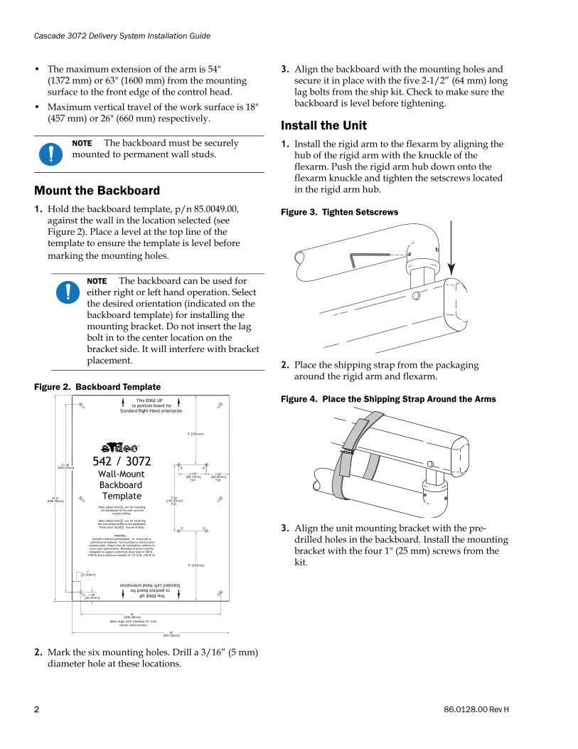
Install the Unit1. Install the rigid arm to the flexarm by aligning the
hub of the rigid arm with the knuckle of the flexarm. Push the rigid arm hub down onto the flexarm knuckle and tighten the setscrews located in the rigid arm hub.
Figure 3. Tighten Setscrews
2. Place the shipping strap from the packaging around the rigid arm and flexarm.
Figure 4. Place the Shipping Strap Around the Arms
3. Align the unit mounting bracket with the pre-drilled holes in the backboard. Install the mounting bracket with the four 1" (25 mm) screws from the kit.
NOTE The backboard must be securely mounted to permanent wall studs.
NOTE The backboard can be used for either right or left hand operation. Select the desired orientation (indicated on the backboard template) for installing the mounting bracket. Do not insert the lag bolt in to the center location on the bracket side. It will interfere with bracket placement.
2 86.0128.00 Rev H
Cascade 3072 Delivery System Installation Guide
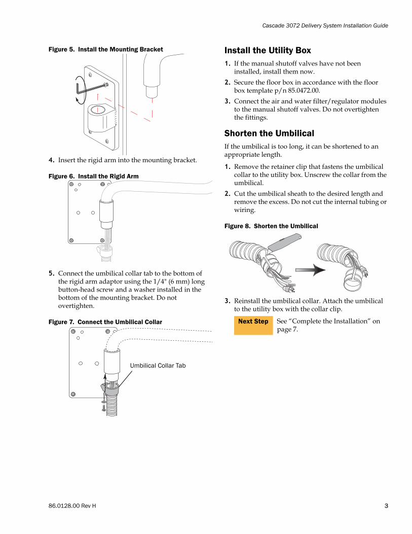
Figure 5. Install the Mounting Bracket
4. Insert the rigid arm into the mounting bracket.
Figure 6. Install the Rigid Arm
5. Connect the umbilical collar tab to the bottom of the rigid arm adaptor using the 1/4" (6 mm) long button-head screw and a washer installed in the bottom of the mounting bracket. Do not overtighten.
Figure 7. Connect the Umbilical Collar
Install the Utility Box1. If the manual shutoff valves have not been
installed, install them now.
2. Secure the floor box in accordance with the floor box template p/n 85.0472.00.
3. Connect the air and water filter/regulator modules to the manual shutoff valves. Do not overtighten the fittings.
Shorten the UmbilicalIf the umbilical is too long, it can be shortened to an appropriate length.
1. Remove the retainer clip that fastens the umbilical collar to the utility box. Unscrew the collar from the umbilical.
2. Cut the umbilical sheath to the desired length and remove the excess. Do not cut the internal tubing or wiring.
Figure 8. Shorten the Umbilical
3. Reinstall the umbilical collar. Attach the umbilical to the utility box with the collar clip.
Umbilical Collar Tab
Next Step See “Complete the Installation” on page 7.
86.0128.00 Rev H 3
Cascade 3072 Delivery System Installation Guide
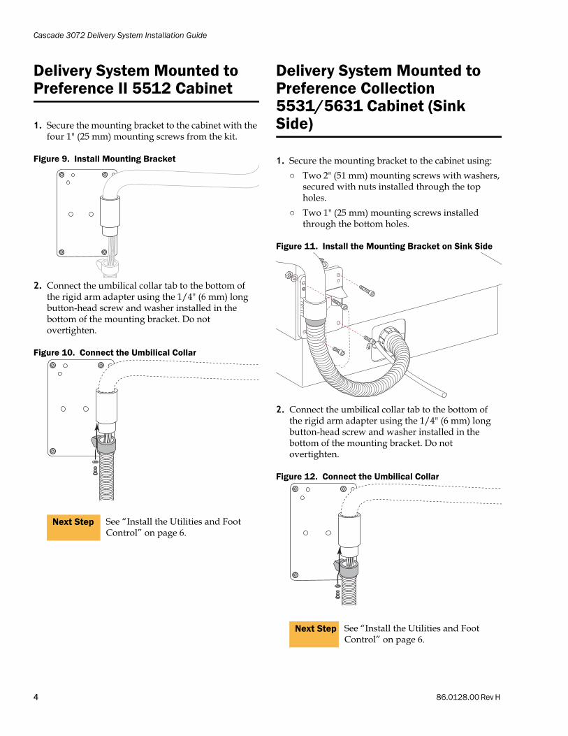
Delivery System Mounted to Preference II 5512 Cabinet
1. Secure the mounting bracket to the cabinet with the four 1" (25 mm) mounting screws from the kit.
Figure 9. Install Mounting Bracket
2. Connect the umbilical collar tab to the bottom of the rigid arm adapter using the 1/4" (6 mm) long button-head screw and washer installed in the bottom of the mounting bracket. Do not overtighten.
Figure 10. Connect the Umbilical Collar
Delivery System Mounted to Preference Collection 5531/5631 Cabinet (Sink Side)
1. Secure the mounting bracket to the cabinet using:
○ Two 2" (51 mm) mounting screws with washers, secured with nuts installed through the top holes.
○ Two 1" (25 mm) mounting screws installed through the bottom holes.
Figure 11. Install the Mounting Bracket on Sink Side
2. Connect the umbilical collar tab to the bottom of the rigid arm adapter using the 1/4" (6 mm) long button-head screw and washer installed in the bottom of the mounting bracket. Do not overtighten.
Figure 12. Connect the Umbilical Collar
Next Step See “Install the Utilities and Foot Control” on page 6.
Next Step See “Install the Utilities and Foot Control” on page 6.
4 86.0128.00 Rev H

Cascade 3072 Delivery System Installation Guide
Delivery System Mounted to Preference Collection 5531/5631 Cabinet to Storage or Drawer Side
1. Remove the drawers or door.
2. Complete drilling the two holes on the wall of the storage or drawer side.
3. Secure the mounting bracket to the cabinet using:
○ Two 1" (25 mm) mounting screws installed through the bottom holes.
○ Two 2" (51 mm) mounting screws with washers, secured with nuts installed through the top holes.
Figure 13. Install the Mounting Bracket on Storage or Drawer Side
4. Connect the umbilical collar tab to the bottom of the rigid arm adapter using the 1/4" (6 mm) long button-head screw and washer installed in the bottom of the mounting bracket. Do not overtighten.
5. Route the umbilical cord through the metal chase and into the sink module.
Delivery System Mounted to Preference II 5612 Cabinet
1. Align the L-shaped mounting adapter cabinet support (from the ship kit) to mounting holes located on the underside of the cabinet. Install the
mounting adapter to the cabinet using the two 1-1/4" (30 mm) cap screws from the kit.
Figure 14. Install the L-shaped Mounting Adapter
2. Remove the control head rigid arm, then install the unit mounting bracket to the cabinet using the four 1" (25 mm) screws from the kit.
Figure 15. Install the Mounting Bracket
3. Reinstall the control head rigid arm to the mounting bracket.
4. Connect the umbilical collar tab to the bottom of the rigid arm adapter using the 1/4" (6 mm) long button-head screw and washer installed in the bottom of the mounting bracket. Do not overtighten.
Figure 16. Connect the Umbilical Collar
Next Step See “Install the Utilities and Foot Control” on page 6.
Next Step See “Install the Utilities and Foot Control” on page 6.
86.0128.00 Rev H 5

Cascade 3072 Delivery System Installation Guide
Delivery System Mounted to Preference Collection 5543 Central
1. Install the mounting bracket to the cabinet using four 2" (51 mm) mounting screws with washers, secured with nuts.
Figure 17. Install Mounting Bracket
2. Connect the umbilical collar tab to the bottom of the rigid arm adapter using the 1/4" (6 mm) long button-head screw and washer installed in the bottom of the mounting bracket. Do not overtighten.
Figure 18. Connect the Umbilical Collar
Install the Utilities and Foot Control
1. If the manual shutoff valves have not been installed, install them now.
2. Remove the plug, if present, from the cabinet base.
Figure 19. Remove the Plug from Cabinet Base
3. Remove the cabinet door (for the 5512).
Figure 20. Remove the Cabinet Door
4. Remove the false bottoms inside the cabinet to access the utilities, if necessary. Route the foot control tubing to the grommet, then install the grommet to the notch in the mounting bracket.
5. Route the umbilical through the large hole in the cabinet base or through the hole in the bottom of the sink cabinet. See Figure 21.
6. Use the collar clip to retain the umbilical inside the cabinet base.
Figure 21. Route the Umbilical
Next Step See “Install the Utilities and Foot Control”.
1 2 3 4 5 6 7 8
6 86.0128.00 Rev H

Cascade 3072 Delivery System Installation Guide
7. Connect the air and water filter/regulator modules to the manual shutoff valves. Do not overtighten the fittings. The modules should be positioned at an angle to provide easy access to the filter element on each manifold (see Figure 22).
8. Match and connect the foot control tubing to the corresponding tubing coming from the umbilical.
Figure 22. Tubing Flow Diagram
A) Fittings to Connect to Shutoff Valves; B) Air Regulators C) Water Filter Regulator
Figure 23. Umbilical to Foot Control Tubing Connections
Complete the Installation
Install the Optional Power SupplyInstall the power supply now. Refer to the instructions that came with the power supply. Do not plug in the power supply at this time.
Insert the Rotation StopsInsert the rotation stop pins from the ship kit in the mount arm and the control arm. The pins are installed with the large diameter end down.
Figure 24. Insert Rotation Stops
Level the Delivery System1. While holding the flexarm down, remove the
shipping strap from the arm. Allow the arm to slowly extend.
2. Extend the arm to its full length. Place a leveling device on the rigid arm to check that it is level.
○ To level the arm system parallel to the wall or cabinet, loosen the mounting plate screws and rotate the plate slightly. Tighten the screws.
○ To level the arm perpendicular to the wall or cabinet, insert shims from the hardware kit between the mounting plate and the backboard.
Figure 25. Level the Bracket
NOTE If necessary, disconnect the air and water filter/regulators, pull the tubing from the umbilical into the cabinet, then reconnect both regulators to the umbilical tubing.
10
20
30
4050
60
70
80
90
1000
0
1
2
3 4
5
6
7
psi
kg/cm2
AB
C WARNING The flexarm is spring loaded. To avoid injury, hold it securely while removing the shipping strap.
1 2 3 4 5 6 7 8
86.0128.00 Rev H 7

Cascade 3072 Delivery System Installation Guide
Level the Control Head1. Place a leveling device on top of the control head to
ensure it is level.
2. Loosen the two locking screws located underneath the control head.
3. Level the control head by turning the two leveling screws, under the control head, clockwise and counterclockwise until the control is level. Tighten the locking screws.
Figure 26. Level the Control Head
Install the Water Bottle
Install the water bottle using the Cascade 3072 Self-Contained Water System Installation Guide, p/n 85.0564.00, that shipped with the water bottle.
Test the Delivery System
1. Fill the self-contained water bottle with water specified by the doctor.
2. Align the bottle with the self-contained water supply cap, making sure the 1/4" clear tubing extends straight down into the water bottle. Screw the water bottle onto the cap until it is snug.
3. Fully open the manual air shutoff valve.
4. Move the master on/off toggle (located on the control head) to the on position.
5. Check the system pressure gauges in the utility box. Air pressure should be 70–80 psi (483–552 kPa) and water pressure should be 35–40 psi (241–276 kPa).
6. Check for air and water leaks while operating the syringe.
○ Air—Press the right button down.
○ Water—Press the left button down.
○ Spray—Press both buttons down.
7. If an optional power supply is installed, plug it in.
8. Test all optional electrical accessories. Refer to each electrical accessory Owner’s Guide for testing and adjustment procedures.
Regulatory Information
Regulatory information is provided with A-dec equipment as mandated by agency requirements. This information is delivered in the equipment’s Instructions for Use or the separate Regulatory Information, Specifications, and Warranty document. If you need this information, please go to the Document Library at www.a-dec.com.
Leveling Screws
Locking Screws
A-dec Headquarters2601 Crestview DriveNewberg, OR 97132 USATel:1.800.547.1883 Within USA/CanadaTel:1.503.538.7478 Outside USA/CanadaFax:1.503.538.0276www.a-dec.com / www.a-dec.biz
A-dec Inc. makes no warranty of any kind with regard to the content in this document including, but not limited to, the implied warranties of merchantability and fitness for a particular purpose.
ÍvÈ.Ç!<È.00ZÎ
86.0128.00 Rev HCopyright 2014 A-dec Inc.
All rights reserved.IGevbw4