
CARRIER COMMERCIAL REFRIGERATION, INC. SERVICE & … · 2015-04-16 · SERVICE & INSTALLATION...
41
SERVICE & INSTALLATION MANUAL CARRIER COMMERCIAL REFRIGERATION, INC. Providing BEVERAGE-AIR • FRIGIDAIRE • KELVINATOR • UNIVERSAL NOLIN Products/Services Frozen Food & Ice Cream Merchandisers CMCT 2/03 51-1021-01
Transcript of CARRIER COMMERCIAL REFRIGERATION, INC. SERVICE & … · 2015-04-16 · SERVICE & INSTALLATION...

SERVICE &INSTALLATIONMANUAL
CARRIER COMMERCIAL REFRIGERATION, INC.
Providing BEVERAGE-AIR • FRIGIDAIRE • KELVINATOR • UNIVERSAL NOLIN Products/Services
Frozen Food& Ice CreamMerchandisersCMCT
2/03 51-1021-01

If additional information is necessary, call the factory.
Our toll free number is 1-800-684-1199. Technical assis-tance engineers are willing to assist you in any way possi-ble. Office hours are from 8:00a.m. to 5:30 p.m., EasternStandard Time.
Important information is contained in this manual which shouldbe retained in a convenient location for future reference.
All data and information in this manual is subject to change without notice.
MODEL DESIGNATION INFORMATION115V, 60HZ
PART # MODEL # DATA PLATE52-2038-01 CMCT4-4 SL12/CMCT452-2038-03 CMCT6-4 SL20/CMCT652-2038-05 CMCT8-4 SL28/CMCT852-2038-06 CMCT10-4 SL36/CMCT10
EXPORT 220V, 50HZPART # MODEL # DATA PLATE52-2040-01 ECMCT4-4 ECMCT452-2040-02 ECMCT6-4 ECMCT652-2040-04 ECMCT8-4 ECMCT8

SECTION IIntroduction
CMCT Merchandisers – Introduction
These cabinets are produced for the merchandising of frozenfood and ice cream markets. They range in size from 4' to 10'in length. Operating ambients range from 70ºF. to 85ºF. withcavity temperatures at load line between 0ºF. to -20ºF.
Except for routine cleaning, these cabinets will require littlemaintenance. In the unusual event that repair should benecessary, this manual presents information that is helpful inmaintaining, diagnosing, and repairing these cabinets.
INTRODUCTION 3

TABLE OF CONTENTS
4 TABLE OF CONTENTS
Due to the manufacturer’s policy of continuous quality improvement, specifications are subject to change without notice.
INTRODUCTIONIntroduction .................................................................... 3Table of Contents ............................................................ 4Specifications & Illustrations ............................................ 5Handling & Installation .................................................... 6Cleaning Instructions ........................................................ 7Cabinet Operation ............................................................ 7Electrical Data .................................................................. 9Refrigeration/Electrical Specs. (R404A)............................ 10Refrigeration/Electrical Data Export Models...................... 11Wiring Diagram CMCT Models 4, 6 & 8 .......................... 12Wiring Diagram CMCT Models 10 .................................... 13Wiring Diagram ECMCT Models 4, 6 & 8 (Export) .......... 14Lamp Wiring Detail (Upper Raceway) .............................. 15
MAINTENANCE & REPAIRCabinet Temperature Control ............................................ 19Electrical Box Layout ........................................................ 20Defrost Timer Layout ........................................................ 21Cabinet Electrical Supply .................................................. 22Condensing Unit Assembly .............................................. 23Condensing Unit Layout.................................................... 24Unit Compartment - Rear.................................................. 25Evaporator Tubing Illustration .......................................... 26New Lubricants ................................................................ 27Back Pressure Valve ........................................................ 28Light Channel Assembly .................................................. 29Baffle Heater comp. ID & Removal .................................. 30End Panel Breaker & Heater Removal .............................. 31Refrig. Upper Section Comp. ID & Removal .................... 32Upper Cross Section ........................................................ 33Front Glass Heater Replacement ...................................... 34Countertop ........................................................................ 35Evaporator Coil Removal .................................................. 36Troubleshooting Guide...................................................... 38
PARTS LISTSCMCT Cabinet Exterior Parts ID ...................................... 40Parts List CMCT-4, 6, 8 & 10............................................ 41Parts List EMCT-4, 6 & 8.................................................. 42

Specifications - Specifications Subject to Change without Notice.
CMCT-4 CMCT-6 CMCT-8 CMCT-10Temperature Range 0° to -20°F 0° to -20°F 0° to -20°F 0° to -20°F
Insulation 21⁄2" Urethane Foam in Place 21⁄2" Urethane Foam in Place 21⁄2" Urethane Foam in Place 21⁄2" Urethane Foam in Place
Number of Lids 2 2 3 4Lid Construction 3/16" Glass Radiant Heated 3/16" Glass Radiant Heated 3/16" Glass Radiant Heated 3/16" Glass Radiant Heated
Capacity 11 cu. ft. 19 cu. ft. 27 cu. ft. 35 cu. ft.
Capacity (1/2 gallons) 120 225 322 435
Novelty Baskets Load Level 10 14 20 26
Capacity Novelty Baskets Total 16 24 36 48
Shipping Weight (Approx.) 486 lbs. 624 lbs. 780 lbs. 874 lbs.
Compressor Size 1/2 HP 1/2 HP 3/4 HP 1 HP
Condenser Type Bare Tube Forced Air Bare Tube Forced Air Bare Tube Forced Air Fin & Tube Forced Air
Evaporator Type Fin & Tube Gravity Coil & Cold Wall Fin & Tube Gravity Coil & Cold Wall Fin & Tube Gravity Coil & Cold Wall Fin & Tube Gravity Coil & Cold Wall
Refrigerant Type R404A R-404A R-404A R-404A
Refrigerant Control Capillary Capillary Capillary Capillary
Defrost System Electric Electric Electric Electric
Rated Amps 8.0 8.0 12 4.8 (11V0/6.7 (230V)
Electrical Specs. (V/Hz/Ph) 115/60/1 115/60/1 115/60/1 115 & 230/60/1
Power Cord 15 Amp Cord 15 Amp Cord 15 Amp Cord Conduit Connected / Max. Fuse
with 5-15P NEMA Plug with 5-15P NEMA Plug with 5-15P NEMA Plug Size 15A Min. Circuit Ampacity 15A
NSF-7 (Ice Cream Storage) Yes Yes Yes Yes
UL & CUL Listed Yes Yes Yes Yes
Interior Finish White Baked Enamel White Baked Enamel White Baked Enamel White Baked Enamel
Exterior Finish White Baked Enamel White Baked Enamel White Baked Enamel White Baked Enamel
Lighted Sign Standard Standard Standard Standard
INTRODUCTION 5
481/16 (CMCT4)721/16 (CMCT6)961/16 (CMCT8)
1201/16 (CMCT10)423/4 (CMCT4)663/4 (CMCT6)783/4 (CMCT8)
1143/4 (CMCT10)INSIDE
329/16
19
253/4
INSIDE
383/4

FREIGHT DAMAGES AND SHORTAGES
The cabinet was inspected andpackaged at the factory, and should
arrive in excellent condition. The transportation companyor other parties involved in the shipment are responsiblefor loss and/or damage. Always make an inspectionbefore and after uncrating. Inspect the crated unit(s)before locating (preferably at the point of unloading bythe transportation company).
INSPECTING FOR DAMAGESAlways use care when removing shippingtape, blocks, pads, hardware or other material
until you are satisfied that the unit is completely opera-tional.
Check the cartons or containers. If these are damagedin any way, open them and inspect the contents in thedriver’s presence. If damage is detected:
1. Have the driver note the nature and extent of thedamage on the freight bill.
2. Notify the transportation company’s office to requestan inspection. Carrier claim policies usually requireinspections to be made within 15 days of delivery.
3. If damage is noticed, file a claim with the transporta-tion company.
FILING A CLAIMFile a claim for loss at once with the transportationcompany for:
A. A cash adjustment; B. Repairs; or C. Replacement
When filing your claim, retain all packaging materialsand receipts.
HANDLING THE CABINETThe refrigeration system of the cabinet isdesigned to operate with the cabinet located
on a level surface. Do not tilt the cabinet more than10° to any side. If the cabinet must be tilted on anangle for handling or moving purposes, allow it to sit inan upright position 30 minutes prior to starting.
CHOOSING A LOCATIONThis model cabinet should be situated to allow proper aircirculation. Cabinets require a 2" minimum clearancebehind for proper air circulation.
The cabinet must be installed on a sturdy, solid, levelfloor.
The cabinet must be located so it can be plugged orwired into a properly grounded three-prong electricaloutlet of 115/220 volt, 60 hz.The electrical outlet shouldnot be controlled by a wall switch which might be turnedoff accidentally.
UNCRATING THE CABINETThe cabinet should be moved as close as possible tothe operating location before removing crate base. Besure to follow the steps in the “INSPECTING FORDAMAGES” instructions.
INSTALLING THE CABINETAfter removing the skid from the cabinet, slide cabinetinto location. Level cabinet to insure proper draining ofthe defrost water.
To meet NSF requirements, these cabinets must besealed to the floor with an NSF or FDA approvedsealant.
Remove the front grill from cabinet. Remove front holddown bolts and pull unit out of cabinet. Remove ship-ping band from compressor. Be sure that the compres-sor “floats” freely on the compressor springs. Checkrefrigeration lines to see that they are “free” and nodamage was done in shipping. Check fan blade for freeoperation.
Check voltage and amp draw on the serial plate todetermine proper fuse and line size. Voltage should bechecked at the compressor terminals as the compres-sor is starting, to determine if there is excessive “volt-age drop.” This voltage drop should not exceed 10% ofthe rated compressor voltage. If the voltage reads 115or 230 with no load and it drops below 103 or 208 whenthe compressor tries to start, it is an indication that thesupply wiring is too small in size or too long in length.
It is recommended that a separate circuit be run for eachcabinet to prevent the possibility of another applianceblowing a fuse causing subsequent loss of product.
SECTION I – HANDLING & INSTALLATION
6 INTRODUCTION
NOTE:
IMPORTANT:
NOTE:

CLEANING INSTRUCTIONSCLEANING THE CABINET EXTERIORWipe the exterior occasionally with a cloth dampened inmild detergent water; rinse, and wipe dry with a soft,dry cloth. Do not use abrasive or caustic cleaners orscouring pads.
CLEANING THE CONDENSERPeriodic cleaning of the condenser can be easilyaccomplished by brushing the coils with a soft brushand/or using a vacuum cleaner with a brush attach-ment.
Be sure that dirt, dust, and a collection of other debrisdo not build up to a point that air circulation through thecondenser is restricted.
CLEANING THE STORAGE COMPARTMENT1. Remove product and store it in another suitable cab-
inet, if possible. Be sure to prevent spoilage of theproduct which may occur if it is left at room temper-ature.
2. Turn OFF the thermostat and unplug the cabinet.
3. Defrost completely prior to cleaning.
4. Wash the entire interior storage area with warmwater and baking soda solution — about a table-spoon of baking soda per quart of water. Rinse thor-oughly with clean water and wipe dry.
5. A drain hose is provided. Connections are made tofit a standard garden hose for ease of draining waterfrom inside of the tank area.
IMPORTANT:Do not use any objects or cleaners which may leaveresidues, odors, or particles. Avoid the use of strongchemicals or abrasive cleaners which may damage theinterior surfaces and contaminate product within thestorage area.
6. Be sure to correctly plug in to cabinet, set the tem-perature control, and allow time for cooling of thestorage area before storing product.
DESCRIPTION OF REFRIGERATIONSYSTEM: CONDENSING UNITAll CMCT cabinets are equipped with Copelameticcompressors utilizing 404A refrigerant:
1/2 HP on the CMCT-4 and CMCT-6
3/4 HP on the CMCT-8
1 HP on the CMCT-10
A back pressure valve is used to protect the compres-sor against excessive pressures during initial cabinetstart-up and upon termination of the defrost cycle. Thisvalve is factory pre-set to limit the crankcase pressureto 10# and should not be changed.
CABINET OPERATIONREFRIGERATION CYCLE:Refrigeration is accomplished by both a “wrap-around”tank coil and fin coil. This tank coil consists of severalpasses of copper tubing wrapped completely around thetank or product compartment.The fin coil located behindthe light fixture serves two purposes — it creates a blan-ket of cold air over the product and collects moisture inthe form of frost from the warm air entering the cabinet,thus reducing frost collection on the tank coil. The refrig-erant enters the top of the tank coil first and progressesdownward to the bottom of the tank; from there it entersthe top of the fin coil and again downward. By circuitingthe refrigeration in this manner, it assures the fin coil ofbeing the coldest part of the system.
DEFROST CYCLE:Because of the large size and fin arrangement, theCMCT fin coils have the ability to collect a large amountof frost before becoming blocked.These features permitthe CMCT cabinets to operate on one defrost cycle per24 hours, thus reducing product shock to the ice cream.
The fin coil and drain pan are defrosted with one 4-pass heater located on the underside of the evaporatorassembly. The back pass of the heater lays in the draintrough which slopes from left to right along the backedge of the drain pan.
WARNING:To avoid the possibility of an electrical shock, turn OFF thermostat and unplug the electrical cord of the cabinetbefore cleaning or touching electrical connections or parts.
INTRODUCTION 7

Defrosting is initiated by the time clock and terminatedby a temperature thermostat set to close at 76°F. Whenthis thermostat closes, it energizes a solenoid in thetime clock which in turn trips the clock mechanism offdefrost. Should this thermostat fail to close, the defrostcycle will be terminated by the failsafe pin on the timeclock (set at 40 minutes).
As an additional safety feature, the temperature limitingthermostat is wired in series with the defrost heater.This thermostat will also open the heater circuit whenthe top coil reaches 76°F. should any malfunction of thedefrost thermostat occur.
Any time the system has been opened andexposed to the atmosphere, a new drier
should be installed, system completely evacuated, andrecharged to the specified refrigerant and amount list-ed on the serial plate located inside the unit compart-ment on the left wall.
DO NOT ATTEMPT CHARGING BYPRESSURES ALONE!! Charge is
very critical! Charging should be accomplished bymeans of weighing, or the use of a charging cylinder.
NOTE:
IMPORTANT:
8 INTRODUCTION

CMCT ELECTRICAL DATA
CMCT-4 OHMS WATTS AMPS VOLTS
Def. Heater on Bottom side24.7 582 4.8 120
of Top Coil
Control Bellows Heater below1600 9 .075 120
Def. Controls
End Breaker Heater behind960 15 .12 120
each End Breaker
Glass Heater around262 56 .46 120
Front Glass
CMCT-8 OHMS WATTS AMPS VOLTS
Def. Heater on Bottom side11.8 1200 10 120
of Top Coil
Control Bellows Heater below1600 9 .075 120
Def. Controls
End Breaker Heater behind960 15 .12 120
each End Breaker
Glass Heater around134 107 .89 120
Front Glass
CMCT-6 OHMS WATTS AMPS VOLTS
Def. Heater on Bottom side15.9 904 7.5 120
of Top Coil
Control Bellows Heater below1600 9 .075 120
Def. Controls
End Breaker Heater behind960 15 .12 120
each End Breaker
Glass Heater around175 82 .68 120
Front Glass
CMCT-10 OHMS WATTS AMPS VOLTS
Def. Heater on Bottom side3.38 1561 6.7 230
of Top Coil
Control Bellows Heater below1600 9 .075 120
Def. Controls
End Breaker Heater behind960 15 .12 120
each End Breaker
Glass Heater around190 132 1.1 120
Front Glass
INTRODUCTION 9
10 INTRODUCTION
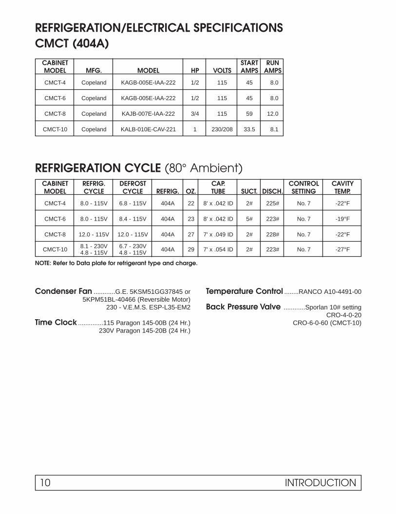
REFRIGERATION/ELECTRICAL SPECIFICATIONSCMCT (404A)
CABINET START RUNMODEL MFG. MODEL HP VOLTS AMPS AMPS
CMCT-4 Copeland KAGB-005E-IAA-222 1/2 115 45 8.0
CMCT-6 Copeland KAGB-005E-IAA-222 1/2 115 45 8.0
CMCT-8 Copeland KAJB-007E-IAA-222 3/4 115 59 12.0
CMCT-10 Copeland KALB-010E-CAV-221 1 230/208 33.5 8.1
REFRIGERATION CYCLE (80° Ambient)CABINET REFRIG. DEFROST CAP. CONTROL CAVITYMODEL CYCLE CYCLE REFRIG. OZ. TUBE SUCT. DISCH. SETTING TEMP.
CMCT-4 8.0 - 115V 6.8 - 115V 404A 22 8' x .042 ID 2# 225# No. 7 -22°F
CMCT-6 8.0 - 115V 8.4 - 115V 404A 23 8' x .042 ID 5# 223# No. 7 -19°F
CMCT-8 12.0 - 115V 12.0 - 115V 404A 27 7' x .049 ID 2# 228# No. 7 -22°F
8.1 - 230V 6.7 - 230VCMCT-10 404A 29 7' x .054 ID 2# 223# No. 7 -27°F4.8 - 115V 4.8 - 115V
NOTE: Refer to Data plate for refrigerant type and charge.
Condenser Fan ............G.E. 5KSM51GG37845 or Temperature Control ........RANCO A10-4491-005KPM51BL-40466 (Reversible Motor)
230 - V.E.M.S. ESP-L35-EM2 Back Pressure Valve ............Sporlan 10# settingCRO-4-0-20
Time Clock ..............115 Paragon 145-00B (24 Hr.) CRO-6-0-60 (CMCT-10)230V Paragon 145-20B (24 Hr.)
INTRODUCTION 11
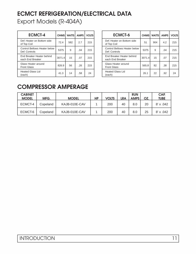
ECMCT REFRIGERATION/ELECTRICAL DATAExport Models (R-404A)
ECMCT-4 OHMS WATTS AMPS VOLTS
Def. Heater on Bottom side72.4 582 2.7 215
of Top Coil
Control Bellows Heater below5375 9 .04 215
Def. Controls
End Breaker Heater behind3071.4 15 .07 215
each End Breaker
Glass Heater around826.9 56 .26 215
Front Glass
Heated Glass Lid41.3 14 .58 24
(each)
ECMCT-6 OHMS WATTS AMPS VOLTS
Def. Heater on Bottom side51 904 4.2 215
of Top Coil
Control Bellows Heater below5375 9 .04 215
Def. Controls
End Breaker Heater behind3071.4 15 .07 215
each End Breaker
Glass Heater around565.8 82 .38 215
Front Glass
Heated Glass Lid26.1 22 .92 24
(each)
COMPRESSOR AMPERAGECABINET RUN CAP.MODEL MFG. MODEL HP VOLTS LRA AMPS OZ. TUBE
ECMCT-4 Copeland KAJB-010E-CAV 1 200 40 8.0 20 8' x .042
ECMCT-6 Copeland KAJB-010E-CAV 1 200 40 8.0 25 8' x .042

12 INTRODUCTION
WIRING DIAGRAM – 00-1667-00CMCT-4, 6, & 8
INTRODUCTION 13
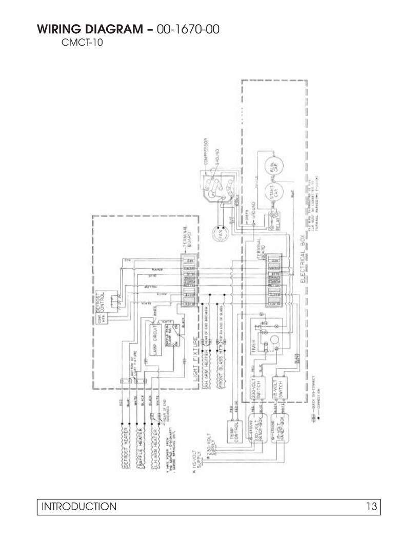
WIRING DIAGRAM – 00-1670-00CMCT-10

14 INTRODUCTION
WIRING DIAGRAM – 00-1934-00ECMCT-4, 6, & 8 (Export Models)
INTRODUCTION 15
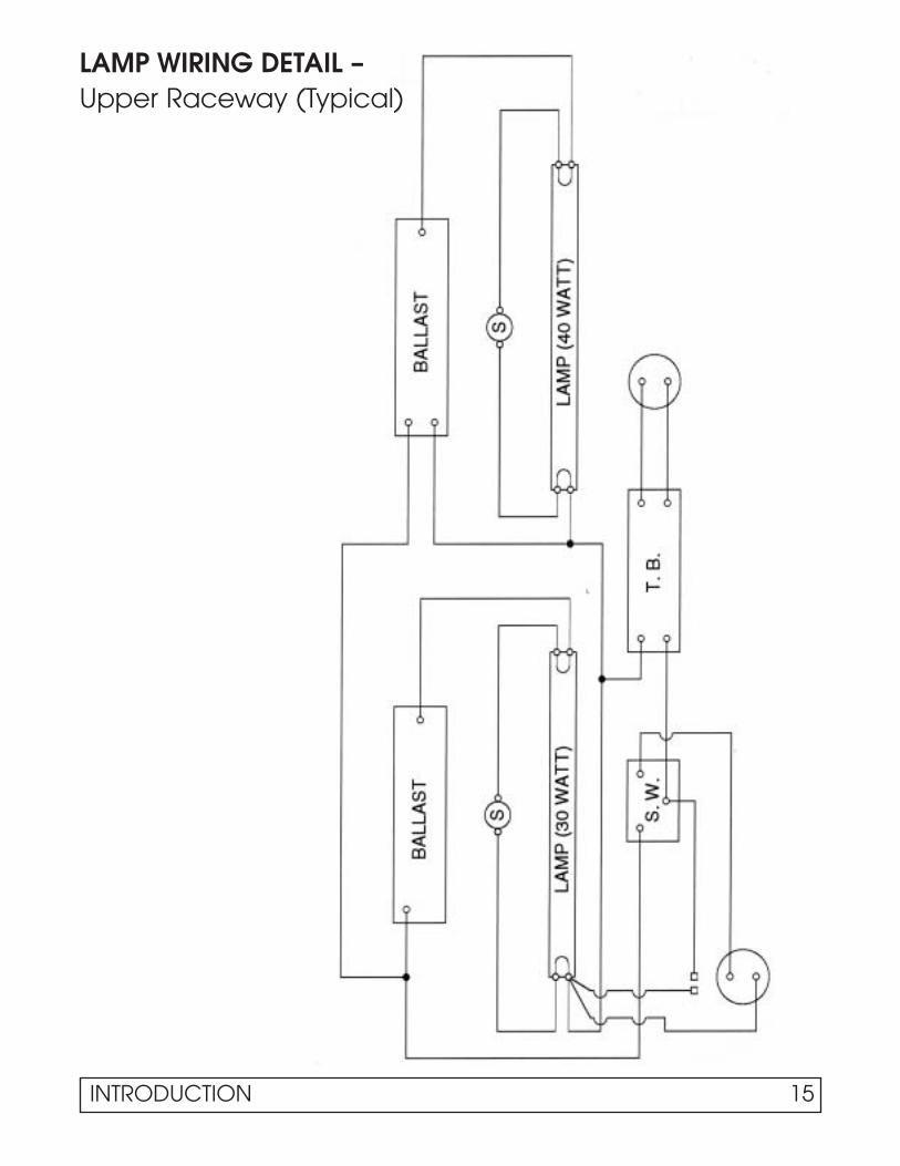
LAMP WIRING DETAIL –Upper Raceway (Typical)

SECTION IIMaintenance & Repair
MAINTENANCE & REPAIR 19
CABINET TEMPERATURE CONTROL
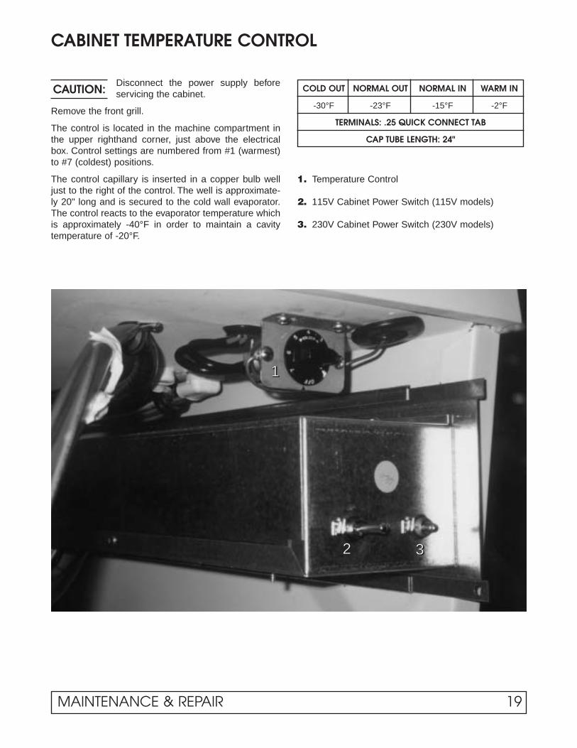
Disconnect the power supply beforeservicing the cabinet.
Remove the front grill.
The control is located in the machine compartment inthe upper righthand corner, just above the electricalbox. Control settings are numbered from #1 (warmest)to #7 (coldest) positions.
The control capillary is inserted in a copper bulb welljust to the right of the control. The well is approximate-ly 20" long and is secured to the cold wall evaporator.The control reacts to the evaporator temperature whichis approximately -40°F in order to maintain a cavitytemperature of -20°F.
CAUTION: COLD OUT NORMAL OUT NORMAL IN WARM IN
-30°F -23°F -15°F -2°F
TERMINALS: .25 QUICK CONNECT TAB
CAP TUBE LENGTH: 24"
1. Temperature Control
2. 115V Cabinet Power Switch (115V models)
3. 230V Cabinet Power Switch (230V models)
1111
2222 3333
ELECTRICAL BOX LAYOUT
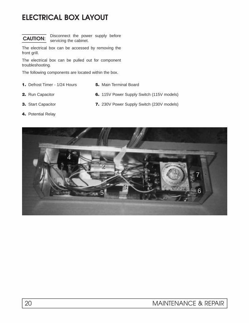
Disconnect the power supply beforeservicing the cabinet.
The electrical box can be accessed by removing thefront grill.
The electrical box can be pulled out for componenttroubleshooting.
The following components are located within the box.
CAUTION:
1. Defrost Timer - 1/24 Hours 5. Main Terminal Board
2. Run Capacitor 6. 115V Power Supply Switch (115V models)
3. Start Capacitor 7. 230V Power Supply Switch (230V models)
4. Potential Relay
11112222
3333
4444
5555 6666
7777
20 MAINTENANCE & REPAIR
DEFROST TIMER LAYOUT
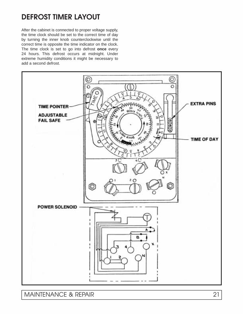
After the cabinet is connected to proper voltage supply,the time clock should be set to the correct time of dayby turning the inner knob counterclockwise until thecorrect time is opposite the time indicator on the clock.The time clock is set to go into defrost once every 24 hours. This defrost occurs at midnight. Underextreme humidity conditions it might be necessary toadd a second defrost.
MAINTENANCE & REPAIR 21
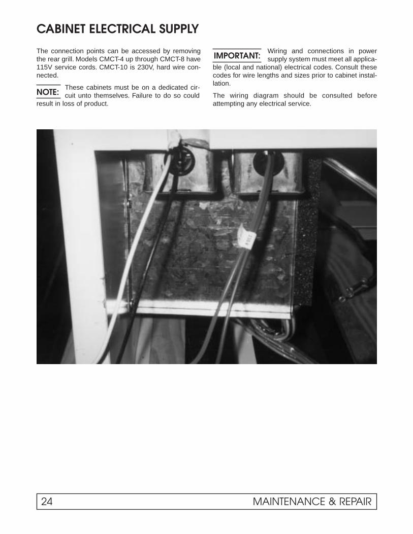
CABINET ELECTRICAL SUPPLY
The connection points can be accessed by removingthe rear grill. Models CMCT-4 up through CMCT-8 have115V service cords. CMCT-10 is 230V, hard wire con-nected.
These cabinets must be on a dedicated cir-cuit unto themselves. Failure to do so could
result in loss of product.
Wiring and connections in powersupply system must meet all applica-
ble (local and national) electrical codes. Consult thesecodes for wire lengths and sizes prior to cabinet instal-lation.
The wiring diagram should be consulted beforeattempting any electrical service.
NOTE:
IMPORTANT:
24 MAINTENANCE & REPAIR

This product utilizes the pull out feature on its low tem-perature applications. This is to aid service personnel inthe event service is needed.
Disconnect the power supply before servicing the cabinet.
1. Remove front grill.
2. Remove two (2) hold down bolts that are located inthe front base rail. Pull unit out for service.
CONDENSING UNIT ASSEMBLY
CAUTION:
MAINTENANCE & REPAIR 23
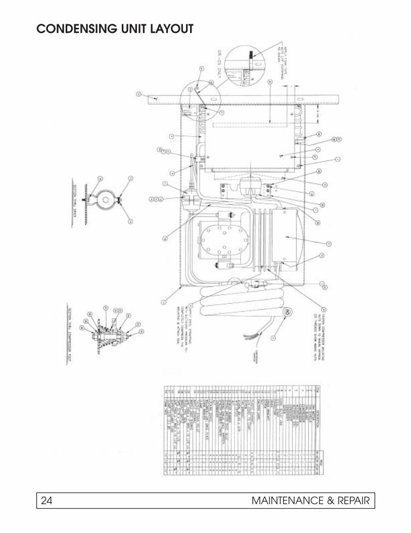
CONDENSING UNIT LAYOUT
24 MAINTENANCE & REPAIR

UNIT COMPARTMENT – REAR
CMCT-10 models still use fin and tube condensers.NOTE:
1111
2222
3333
4444
1. Accordian Coil
2. Process Tube Evaporator
3. Suction Line
4. Cap Tube Inlet
MAINTENANCE & REPAIR 25

EVAPORATOR TUBING ILLUSTRATION
EVAPORATOR TANK WRAP –RH SIDE VIEW:
Evaporator inlet tube on top row.
1. Tank Wrap Inlet
2. #2 Pass
3. #3 Pass
4. Thermostat Bulb Well
5. Condensate Drain
NOTE:
TANK WRAP – FRONT SIDE
6. #1 Pass
7. #2 Pass
8. #3 Pass
9. #4 Pass
10. #5 Pass
Upper evaporator coilconnections are on the
top, left back wall.
NOTE:
EVAPORATOR TANK WRAP – RIGHTHAND REAR OF CABINET:
Capillary tube and heat exchange arefoamed in place. Three lines exit the cabinet shell:
11. 1⁄4" Process Line
12. Capillary Tube
13. Suction Line
If the capillary tube should ever becomerestricted, the 1⁄4" process tube can besubstituted as an evaporator inlet.
26 MAINTENANCE & REPAIR
11112222
3333
4444
5555
66667777
8888
9999
11110000
11111111
11112222
11113333

NEW LUBRICANTS
In switching from refrigerant 502 to refrigerant 404A,the compressor lubricants had to be changed. Oilsused in the compressors in the past were mineralbased. The new oils used are polyol esters. Specialconsideration must be made when handling these oils.Processing procedures must be more rigorous to avoidabsorbing moisture. Also, P.O.E.’s are better solventswhich means they will dislodge and carry debristhrough a system to a far greater extent than do miner-al oils. The oil used in Copeland compressor is MobilArtic EAL-22-CC.
MAINTENANCE & REPAIR 27
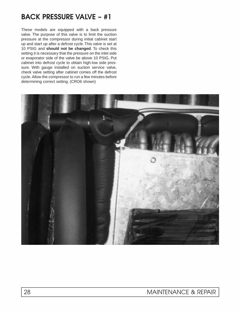
BACK PRESSURE VALVE – #1
These models are equipped with a back pressurevalve. The purpose of this valve is to limit the suctionpressure at the compressor during initial cabinet startup and start up after a defrost cycle. This valve is set at10 PSIG and should not be changed. To check thissetting it is necessary that the pressure on the inlet sideor evaporator side of the valve be above 10 PSIG. Putcabinet into defrost cycle to obtain high-low side pres-sure. With gauge installed on suction service valve,check valve setting after cabinet comes off the defrostcycle. Allow the compressor to run a few minutes beforedetermining correct setting. (CRO6 shown)
1111
28 MAINTENANCE & REPAIR

LIGHT CHANNEL ASSEMBLY – Component Identification
Disconnect the power supply beforeservicing the cabinet.
Wiring from the pull out electrical box is connected viaa wiring harness to the upper lighting channel whichhouses the following components:
CAUTION:
1. Product Reflector 4. Light Ballast
2. Defrost Termination Control 5. Lamp Receptable & Starter
3. Upper Terminal Board 6. Ambient Temperature Compensator
1111
2222
333344445555
6666
MAINTENANCE & REPAIR 29

BAFFLE HEATER COMPONENT IDENTIFICATION& REMOVAL INSTRUCTIONS
1. Baffle Heater
2. Light Switch
3. Light Receptacle – Lefthand side
When light switch is ON, baffle heateris de-energized.NOTE:
Disconnect the power supply beforeservicing the cabinet.
The baffle heater is located just behind the light fixtureat the warm air intake to coil.
The baffle can be accessed by removing screws locatedat the bottom edge of V baffle. The heater is attached atthe back side of the V baffle with self-adhesive tape.
The heater resistance can be checked by unpluggingthe heater at the plug-in connector on the lefthand endof the light channel. The heater is only energized whenthe light is turned OFF.
CAUTION:
1111
11112222
3333
30 MAINTENANCE & REPAIR

END PANEL BREAKER & HEATER REMOVAL
Disconnect the power supply beforeservicing the cabinet.
1. Remove eight (8) screws in the end panel breaker(A) and pull breaker down and out.
2. Disconnect heater leads from end panel breakerheater (A) and pull end panel breaker out.
3. To remove end panel breaker heater, remove tape.
CAUTION:
The heater is taped to the back side of the side arm breaker.NOTE:
AAAA
BBBB
MAINTENANCE & REPAIR 31

REFRIGERATED UPPER SECTION COMPONENTIDENTIFICATION & REMOVAL INSTRUCTIONS1. Defrost Heater Lead Connection 4. Defrost Heater
2. Air Baffle 5. Defrost Heater Retainer Bracket
3. Upper Fin Coil 6. Front Coil Housing Cover Bracket
REMOVAL INSTRUCTIONS:Disconnect the powersupply before servic-
ing the cabinet.
1. Disconnect the defrost heaterleads located on the lower right-hand side of the lamp channel –Figure #1.
2. Remove the air diverter shown asFigure #2. This will expose thedefrost heater rack which is mount-ed to the evaporator fin coil. Heaterand rack assembly can now beremoved.
3. Reattach new heater to rack.NOTE: Last pass of the defrostheater must lay down in the draintrough.
4. Reassemble in reverse order.
CAUTION:
1111
2222
3333
44445555
6666
32 MAINTENANCE & REPAIR
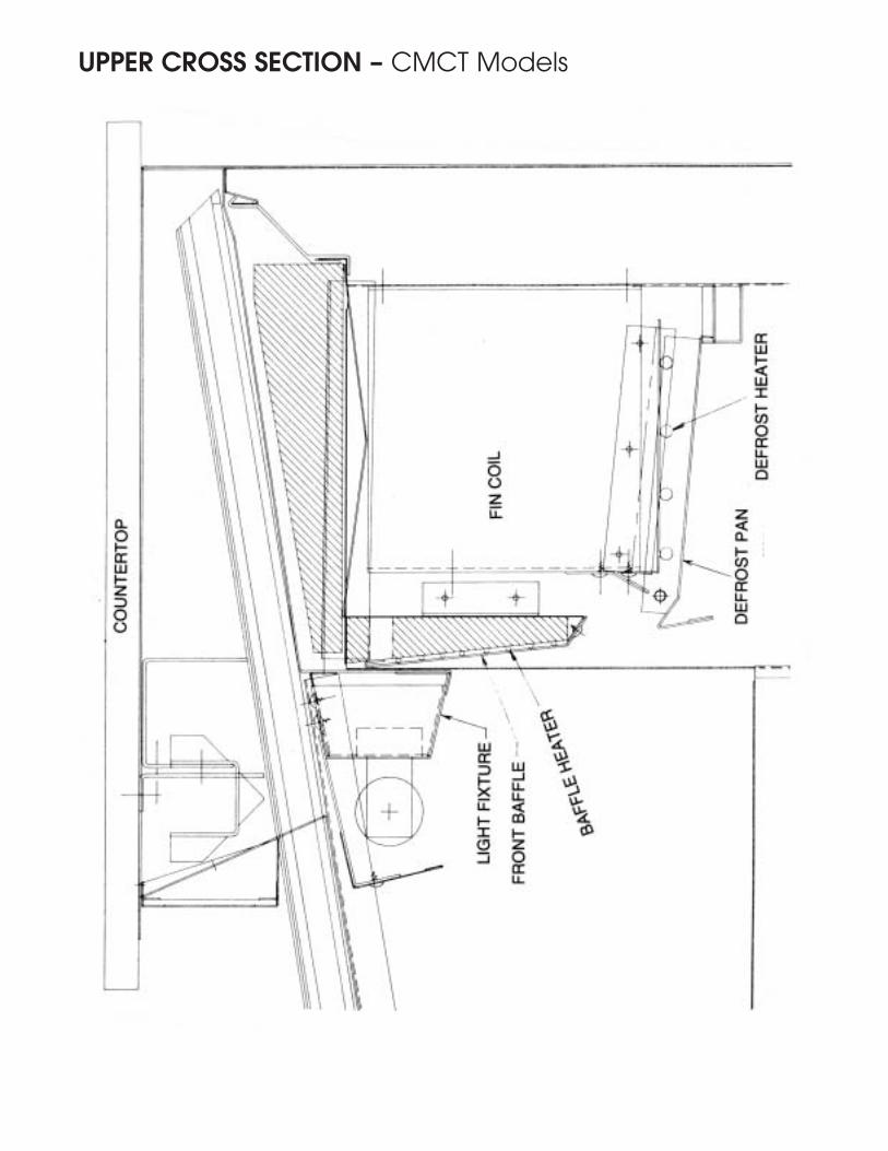
UPPER CROSS SECTION – CMCT Models

FRONT GLASS HEATER REPLACEMENT
Disconnect the power supply beforeservicing the cabinet.
Photograph shows the electrical connection betweenthe cabinet and the front glass heater.
CAUTION:
REMOVAL OF FRONT GLASS HEATERAND/OR END TRACK:1. Remove glass lids.
2. Remove side arm trim (A) at both sides per detail‘A’.
3. Remove three (3) screws in vertical trim post (F)and pull vertical trim post forward. Typical at bothends.
4. Remove three (3) screws in end track (B). Pulltrack forward and lift up. Typical both ends. (Notnecessary for glass removal.)
5. Remove two (2) screws in the front of centertrack (G) and swing center track from dotted lineposition to solid line position.
6. Remove two (2) screws (one each end) on glassrail (C) and lift glass rail straight up.
7. Pull top of front glass (D) forward and lift glassand heater (E) up.
8. To remove end track only, execute the first foursteps. To remove front glass heater, execute thefirst seven steps, omitting step number 4.
NOTE: Pay close attention to the way the heaterwire is arranged on the front glass when replacing.
34 MAINTENANCE & REPAIR

CMCT Models
The countertop can be raised in order to service variousinterior components, as shown below.
1. Product Reflector 4. Upper Electrical Component Housing
2. Defrost Heater Plug 5. Righthand Arm Heater Leads
3. Lamp
MAINTENANCE & REPAIR 35
1111
2222
3333
4444
5555

EVAPORATOR COIL REMOVALDisconnect the powersupply before servicingthe cabinet.
A. Raise up the counter top.
B. Remove screws along the back wallof the sub top.
C. Remove the high air intake bafflelocated on the righthand side of thesub top.
D. Remove the cabinet lids and lid rails.
E. Remove the screws that hold thelight channel to the sub top.
F. Pull the defrost termination bulb outof the evaporator coil bulb well. Liftthe sub top up and out of the cabinet.
CAUTION:
1. Defrost Termination & High Limit Control 3. Defrost Heater Receptacle
2. Defrost Termination Bulb Well 4. Sub Top
G. Lift the insulation up and out of the cabinet. Do notbreak. This will expose the coil housing cover. Thiscover is attached by three screws, one on eachend and one at the rear on the top.
5. Upper Coil Insulation
6. V Baffle Insulation
7. V Baffle Front
36 MAINTENANCE & REPAIR
Reseal bulb well and coil cover with permagumas shown.
8. Coil Cover
9. V Baffle Heater
NOTE:
1111
2222
3333
4444
5555
6666
7777
8888
9999

EVAPORATOR COIL REMOVAL – continued
10. Sub Top
11. Air Diverter
12. Defrost Termination Bulb Well
The view below illustrates the evaporator coil andtube connections on the lefthand end of the cabi-net. Take care when reinstalling the coil housingcover. Reseal areas where moisture could migratedown into the coil area. This coil area runs at atemperature of -40°F.
13. Upper Coil Inlet 14. Upper Coil Outlet
MAINTENANCE & REPAIR 37
11110000
11111111
11112222
1111333311114444

CMCT TROUBLESHOOTING GUIDE
The following is a guide to aid in the proper diagnosingof service problems.
High Head Pressure & High Back Pressure1. Air in system.
2. Defective fan motor or fan blade dragging on con-denser shroud.
3. Defrost heater on during refrigeration cycle due toheater going to ground or defective time clock.
4. Refrigerant over charge.
5. Blocked condenser (dirty)
Low Back Pressure & Low Head Pressure1. Defective back pressure valve—check for proper
setting as described under “Back Pressure Valve.”
2. Shortage of refrigerant—place a temperature indicat-ing device on outlet of top coil (lower lefthand side ofcoil).Temperature should read within 3 to 4 degrees oflow side pressure taken at the compressor suctionservice valve. Add gas slowly until these conditionsare obtained or remove charge with certified recoveryequipment, and recharge with correct charge.
3. Cap tube plugged due to moisture or dirt.
Pressures Normal – Cabinet Warm1. Top coil blocked with frost—see corrective mea-
sures under “Coil Block With Frost.”
2. Refrigerant under charge. Due to the fact that ittakes a considerable amount of under charge beforeit has any great effect on pressures and inaccuracyof gauges it is possible to have normal pressuresand yet have an under charge of refrigerant. Thisunder charge will “starve” the top coil and seriouslyaffect cabinet temperature. To determine correctcharge see #2 under “Low Back Pressure … .”
Coil Blocked With Frost1. Bad timer or timer motor.
2. Bad drafts in store caused by heating or air condi-tioning fans; cabinet located too close to door.
3. Defective defrost heater.
4. Defective defrost terminating thermostat, safetythermostat or defective solenoid in time clock.
4. Either of these (#4) can keep the cabinet from goingthrough a defrost cycle. The defrost thermostat (seewiring diagram) should be in open position betweenterminals 1 & 2 when the cabinet goes into defrost.
4. After the coil reaches 76°F, it closes, energizing asolenoid in the time clock which in turn trips the timeclock mechanism off defrost. Should this thermostatbe in the closed position when the clock trips intothe defrost cycle, it will immediately trip it off again.(NOTE: Switch between terminals 1 & 2 will notopen until thermostat drops below 59°F).
4. If the solenoid in the clock is stuck closed (plungerup), it will have the same effect. To determine whichis at fault, remove the wire from X on the clock andturn clock dial into defrost cycle; if cabinet goes intodefrost, it is the defrost thermostat that is bad. If itstill does not go into defrost, remove clock andinspect the plunger of the solenoid coil.
5. Defective safety thermostat.
5. This thermostat has a SPDT switch with one sidewired in series with the defrost heater. Contactsbetween terminals 2 & 3 should be in the closedposition during the refrigeration cycle. Its only pur-pose is, in case of failure of the defrost timer duringthe defrost cycle, it will open the heater circuit whenthe coil reaches 76°F, preventing any over heating ofthe defrost heater.
5. If this thermostat is in the open position when thecabinet goes into the defrost cycle, the heater willremain off. For access to thermostat connections tocheck continuity, refer to wiring diagram. Disconnectthis thermostat and check with ohmmeter.
5. If for any reason the temperature termination featureis inoperative, the fail safe settings on the timershould be set for 30 minutes defrost time.
Defrost Cycle Too Long – Terminating OnFail Safe (Heater On)1. Bad solenoid in time clock (opening winding).
1. If there is an open circuit in the coil of this solenoid,it will not trip the time clock off defrost when the ther-mostat closes. The cabinet will stay on defrost forthe length of time the fail-safe lever on the time clockis set. (Factory set at 40 minutes.)
2. Defrost terminating thermostat not closing when coilreaches 76°F.
To determine which is at fault, turn clock into defrost,place jumper across X and N on clock. If solenoid isgood, this will trip the clock off defrost indicating that itis the defrost thermostat that is at fault.
Be certain that the defrost thermostat hasreached 76°F before determining that either
the solenoid coil or the thermostat is defective.
NOTE:
38 MAINTENANCE & REPAIR

SECTION IIIParts List

CABINET EXTERIOR PARTS IDENTIFICATIONCMCT Models
1. Vertical Trim Post (RH) 6. Center Track 11. Nameplate
2. End Track (LH) 7. Glass Lid 12. Front Bumper
3. Countertop 8. Glass Rail 13. Bumper Trim
4. End Trim 9. Front Glass 14. Front Trim Panel – Upper
5. Lighted Sign 10. Front Trim Panel – Lower 15. Front Grill
PARTS LIST 41

DOMESTIC CMCT PARTS LIST – R-404
Description CMCT-4 CMCT-6 CMCT-8 CMCT-10
Compressor 16-0322-00 16-0322-00 16-0323-00 16-0324-00Start Relay 17-0163-00 17-0163-00 17-0163-00 17-0167-00Start Capacitor 17-0164-00 17-0164-00 17-0165-00 17-0168-00Run Capacitor 17-0166-00 19-2678-00Condenser Coil 51-0709-02 51-0709-02 51-0709-03 18-0533-00Fan Motor 19-0933-00 19-0933-00 19-0933-00 19-0304-00Fan Blade 19-0101-00 19-0101-00 19-0101-00 19-0706-00Drier/ Filter 18-1109-00 18-1109-00 18-1109-00 18-1109-00Heat Exchanger 50-1106-01 50-1106-01 50-1106-03 50-1109-00CRO Valve 18-0365-00 18-0365-00 18-0365-00 18-0315-00Capillary Tube 14-2402-00 14-2402-00 14-2405-00 14-2403-00Evaporator Coil 18-0079-06 18-0079-08 18-0079-10 18-0009-07Heater, Defrost 19-1243-01 19-1243-03 19-1243-05 19-1243-06Thermostat, Defrost Term 19-0833-00 19-0833-00 19-0833-00 19-0833-00Heater, Front Glass 19-0231-01 19-0231-03 19-0231-05 19-0231-06Heater, Baffle 19-0235-07 19-0235-09 19-0235-11 19-0235-12Heater, End Breaker 19-0853-00 19-0853-00 19-0853-00 19-0853-00Thermostat, control 19-0190-00 19-0190-00 19-0190-00 19-0190-00Switch, Power 19-0103-00 19-0103-00 19-0103-00 19-0103-00Time Clock 24-0513 24-0513 24-0513 19-0624-00Service Cord 19-0620-00 19-0620-00 19-0620-00Switch, Light 19-0133-00 19-0133-00 19-0133-00 19-0133-00Ballast, Lamp 30 Watt 19-0458-00 19-0458-00 19-0458-00 19-0458-00Ballast, Lamp 20 Watt 19-0146-00Lamp, Fluorescent 30 Watt 19-0150-00 19-0150-00 19-0150-00 19-0150-00Lamp, Fluorescent 20 Watt 19-0149-00Lamp, Fluorescent 34 Watt 19-0151-00Lampholder 19-0142-00 19-0142-00 19-0142-00 19-0142-00Lampholer w/Starter Socket 19-0143-00 19-0143-00 19-0143-00 19-0143-00Lamp Starter, 30-40 watt 19-0145-00 19-0145-00 19-0145-00 19-0145-00Lamp Starter, 20 watt 19-0144-00Track, LH End 08-0161-01 08-0161-01 08-0161-01 08-0161-01Track, RH End 08-0161-02 08-0161-02 08-0161-02 08-0161-02Track, Center 08-0190-00 08-0190-00 08-0190-00 08-0190-00Track, Lid Slide 10-0200-00 10-0200-01 10-0200-02 10-0200-03Bumper, Front 08-0165-01 08-0165-03 08-0165-05 08-0165-06Trim, Front Bumper 10-0936-01 10-0936-03 10-0936-05 10-0936-06Rail, glass 08-0168-01 08-0168-03 08-0168-05 08-0168-06Post, Vertical Trim LH 08-0518-01 08-0518-01 08-0518-01 08-0518-01Post, Vertical Trim RH 08-0518-02 08-0518-02 08-0518-02 08-0518-02Trim, side Arm 10-0935-00 10-0935-00 10-0935-00 10-0935-00Breaker, End Panel LH 10-0094-01 10-0094-01 10-0094-01 10-0094-01Breaker, End Panel RH 10-0094-02 10-0094-02 10-0094-02 10-0094-02Handle, Lid 10-0218-01 10-0218-03 10-0218-05 10-0218-06Front Grill 50-4192-04 50-4192-04 50-4192-04 50-4192-04Glass, Front 20-0008-01 20-0008-03 20-0008-05 20-0010-00Lid Assy, Glass 50-1756-07 50-1756-09 50-1756-11 50-1756-12Glass, Lid 20-0047-01 20-0047-03 20-0047-05 20-0047-06Counter Top 12-0522-01 12-0522-03 12-0522-05 12-0522-06
Parts List - CMCT's
42 PARTS LIST

EXPORT CMCT PARTS LIST – R-404
Description ECMCT-4 ECMCT-6 ECMCT-8
Compressor 16-0298-00 16-0298-00 16-0290-00Start Relay 17-0167-00 17-0167-00 17-0167-00Start CapacitorRun Capacitor 19-2678-00 19-2678-00 19-2678-00Condenser Coil 51-0709-03 51-0709-03 51-0709-03Fan Motor 19-0501-00 19-0501-00 19-0501-00Fan Blade 19-0101-00 19-0101-00 19-0101-00Drier/ Filter 18-1109-00 18-1109-00 18-1109-00Heat Exchanger 50-1106-02 50-1106-02 50-1106-03CRO Valve 18-0365-00Capillary Tube 14-2402-00 14-2402-00 14-2405-00Evaporator Coil 18-0079-06 18-0079-08 18-0079-10Heater, Defrost 19-0891-01 19-0891-03 19-0891-05Thermostat, Defrost Term 19-0833-00 19-0833-00 19-0833-00Heater, Front Glass 19-0890-01 19-0890-03 19-0890-05Heater, Baffle 19-0907-01 19-0907-03 19-0907-05Heater, End Breaker 19-0893-00 19-0893-00 19-0893-00Thermostat, control 19-0190-00 19-0190-00 19-0190-00Switch, Power 19-0103-00 19-0103-00 19-0103-00Time Clock 19-0864-00 19-0864-00 19-0864-00Service Cord 19-0620-00 19-0620-00 19-0620-00Switch, Light 19-0133-00 19-0133-00 19-0133-00Ballast, Lamp 30 Watt 19-0911-00 19-0911-00 19-0911-00Ballast, Lamp 20 Watt 19-0912-00 22-0200Lamp, Fluorescent 30 Watt 19-0150-00 19-0150-00 19-0150-00Lamp, Fluorescent 20 Watt 19-0149-00Lamp, Fluorescent 34 Watt 19-0151-00Lampholder 19-0142-00 19-0142-00 19-0142-00Lampholer w/Starter Socket 19-0143-00 19-0143-00 19-0143-00Lamp Starter, 30-40 watt 19-0145-00 19-0145-00 19-0145-00Lamp Starter, 20 watt 19-0144-00Track, LH End 08-0161-01 08-0161-01 08-0161-01Track, RH End 08-0161-02 08-0161-02 08-0161-02Track, Center 08-0190-00 08-0190-00 08-0190-00Track, Lid Slide 10-0200-04 10-0200-05 10-0200-06Bumper, Front 08-0165-01 08-0165-03 08-0165-05Trim, Front Bumper 10-0936-01 10-0936-03 10-0936-05Rail, glass 08-0168-01 08-0168-03 08-0168-05Post, Vertical Trim LH 08-0518-01 08-0518-01 08-0518-01Post, Vertical Trim RH 08-0518-02 08-0518-02 08-0518-02Trim, side Arm 10-0935-00 10-0935-00 10-0935-00Breaker, End Panel LH 10-0094-01 10-0094-01 10-0094-01Breaker, End Panel RH 10-0094-02 10-0094-02 10-0094-02Handle, Lid 10-0218-01 10-0218-03 10-0218-05Front Grill 50-4192-04 50-4192-04 50-4192-04Glass, Front 20-0008-01 20-0008-03 20-0008-05Lid Assy, Glass 50-1756-07 50-1756-09 50-1756-11Glass, Lid 20-0047-01 20-0047-03 20-0047-05Counter Top 12-0522-01 12-0522-03 12-0522-05
Export Parts List - CMCT's
PARTS LIST 19


![Welcome! [] · bon chef broaster brown refrigeration bunn-o-matic busboy cadco ... cannibal disposers can pro captive aire carrier commercial refrigeration ... ice-o-matic idea ...](https://static.fdocuments.us/doc/165x107/5bbfebe509d3f22e7d8cffbd/welcome-bon-chef-broaster-brown-refrigeration-bunn-o-matic-busboy-cadco.jpg)


