Carnegie Mellon University - NASA · carnegie institute of technology accected by prithwish basu...
38
0 0 0 - a fl4G3- /6L THERMAL EFFECTS I N TWO-PHASE FLOW THROUGH - FACE SEALS /&-~,5 +,FddT~ /P/-sg-i 72 A DISSERTATION SUBMITTED TO THE GRADUATE SCHOOL I N PARTIAL FULFILLMENT OF THE REQUIREMENTS )75 am for the degree DOCTOR OF PHILOSOPHY in 1 MECHANICAL ENGINEERING bY Pri thwi s h Basu a Pittsburgh, Pennsylvania 0 May 1988 (hASA-CR-l8nt@) ‘LtEGIZAL EIIECIIZ IB N89- 137&8 ILrO-PkASE PLCC lti6CUGH FACk SLBXS Eh.D. 1Cesi.s (Carneqie-8ellcn Oniv.) 106 p LSCL 11A Unclas G.J/37 0175GCU https://ntrs.nasa.gov/search.jsp?R=19890004417 2018-09-13T14:54:03+00:00Z
Transcript of Carnegie Mellon University - NASA · carnegie institute of technology accected by prithwish basu...

0
0
0
- a
fl4G3- / 6 L THERMAL EFFECTS I N TWO-PHASE FLOW THROUGH - FACE SEALS /&-~,5 +,FddT~
/P/-sg-i 72 A DISSERTATION SUBMITTED TO THE GRADUATE SCHOOL
I N PARTIAL FULFILLMENT OF THE REQUIREMENTS )75 am f o r the degree
DOCTOR OF PHILOSOPHY
i n 1 MECHANICAL ENGINEERING
bY
P r i t h w i s h B a s u
a
P i t t s b u r g h , P e n n s y l v a n i a
0 May 1988
( h A S A - C R - l 8 n t @ ) ‘LtEGIZAL EIIECIIZ IB N89- 137&8 ILrO-PkASE P L C C l t i 6 C U G H F A C k SLBXS Eh.D. 1Cesi.s (Carneqie-8ellcn Oniv.) 1 0 6 p
LSCL 11A Unclas G.J/37 0175GCU
https://ntrs.nasa.gov/search.jsp?R=19890004417 2018-09-13T14:54:03+00:00Z
0
a THESIS 8UBMITTED IN PARTIAL FULFILLMENT OF THE REQUIREMENTS
FOR THE DECREE OF Doctor of Philosophy
TITLE "Thermal Effects in Two-Phase Flow .Seal="
a PRESENTED
a
a
Carnegie Mellon University
CARNEGIE INSTITUTE OF TECHNOLOGY
ACCECTED
By Prithwish Basu
,YTHE DECARTWENTOF Mechanical Engineering
APPROVED DY THE COLLEGE COUNCIL

e
e
0
e
CARNEGIE-MELLON UNIVERSITY
THERMAL EFFECTS IN TWO-PHASE FLOW THROUGH FACE SEALS
A DISSERTATION SUBMITTED TO THE GRADUATE SCHOOL
IN PARTIAL FULFILLMENT OF THE REQUIREMENTS
for the degree of e
e
e
0
e
DOCTOR OF PHILOSOPHY in
MECHANICAL ENGINEERING
Prithwish Basu
Pittsburgh, Pennsylvania May, 1988

0 ABSTRACT
a
a
a
When liquid is sealed at a high temperature, it flashes inside the seal due to the pressure drop and/or the viscous heat dissipation. Typical examples of appli- cations are light hydrocarbons in petroleum refineries, hot water in boiler feed pumps and reactor coolant pumps, and cryogenic fluids like liquid oxygen or liy- drogen in rocket turbopumps. The two-phase seals generally exhibit more erratic behavior than their single phase counterparts. Thermal effects, which are often neglected in single phase seal analyses, play an important role in determining a seal behavior under two-phase operation. It is necessary to consider the heat generation due to viscous shear, conduction into the seal rings and convection with the leakage flow. Analytical models developed by the past researchers work reasonably well at the two extremes - for low leakage rates when convection is neglected and for high leakage rates when conduction is neglected. None of the two models addresses the intermediate leakage rate problems when conduction and convection are both important. Most seals, however, operate in this range.
A preliminary model, known as ‘Film Coefficient Model’, has been presented here which considers conduction and convection both, and allows continuous boiling over an extended region unlike the previous low-leakage rate model which neglects convection and always forces a discrete boiling interface.
Another simplified, semi-analytical model, based on the assumption of isotlier- mal condition along the seal interface, has been developed for low leakage rates. This is basically a modification of the previous low leakage rate model and the range of applicablity of both is somewhat limited. The seal performance curves can be obtained quite easily. However, the ‘Film Coefficient Model’ may be used for more accurate and realistic description.
Under certain circumstances, seals seem to exhibit self-sustained oscillations even when all the applied conditions remain steady. This was observed as ax- isymmetric fluctuations in the film thickness accompanied with periodic interface temperature variations. The two models, described earlier, will not be able to predict this anomalous seal behavior. A preliminary transient heat conduction model has been presented here which might help building a compreheiisive model to describe the oscillatory seal behavior.
The advantages and limitations of these models are discussed and some sug- gestions for future works are given.
1
a

DEDICATION To my wife, Suchismita Basu, whose love and deep understanding have given me enornious support throughout this work.
e
e
e
a
ACKNOWLEDGEMENTS
The author would like to express his gratitude to his thesis advisor, Professor William F. Hughes, who gave constant inspirations, encouragements and valuable advice during the course of this work. He indeed serves as an outstanding example of a scholar, a teacher and a friend for those around him.
The author likes to thank his employer, Group R&D, EG&G Sealol, Provi- dence for providing an immense amount of support during the last phase of this thesis work. Thanks are extended to all the author’s colleagues, specially to Mr. James. F. Gardner, Manager of Product Technology, from whom the author has learnt many different aspects of sealing technology.
The author also likes to thank Professor J. H. Griffin for providing generous computer support for this work. Thanks are extended to the other members of the author’s thesis committee, Professors S. C. Yao and D. C. Prieve. Their conimexits and suggestions are greatly appreciated.
This work was supported, in part, by NASA grant number NAG3-166 and a grant from NSF. Thanks are extended to Mr. Robert Hendricks and Ms. Margaret Proctor, who were the project monitors for NASA.
a
iii

NOMENCLATURE
a T
e R T
u
V
11
0
W
z
seal face coning [m/m] opening force [N] nondimensional opening force closing force (N) mass velocity, pu, [kg/m2s] film thickness (seal clearance) [m] nondimensional film thickness ani coefficient for heat transfer [J/(s.m2K)] specific enthalpy [J/kg] thermal conductivity [W/(m.K)] mass leakage rate [kg/s] nondimensional mass leakage rate Nusselt Number pressure [Pa] nondimensional pressure rate of heat conduction per unit area into the seal plates from the fluid [J/(s.mZ)] radial location [m] circumferential location [rad] ideal gas constant (J/(kg.K)] temperature [K] velocity in r-direction [m/s] average velocity in r-direction [m/s] specific volume [m3/kgJ relative axial velocity of the seal rings [m/s] velocity in @-direction [m/s] nondimensional radial distance axial coordinate [nil wall shear stress in radial direction [N/ni2] wall shear stress in circumferential direction [N/m*] viscous dissipation function [J /( s.ni3] density [kg/m3] molecular mean free path [m], qual;t*y or mass fraction of vapor in t.wo-phase mixture viscosity [Pas]
iv

a
e
0
e
a
kinematic viscosity (m2/s] angular velocity (rad/s] nondiinensional angular velocity liquid property gas property, sat,urated vapor property sealed fluid property away from the seal value at the outer radius (high-pressure side) value at the discrete boiling interface value at. the balance radius value at the wall value at the inner radius (low-pressure side) saturated liquid value difference between vapor and liquid saturation properties I( 10 - ()A
e
e
e
V
0

Contents
1 INTRODUCTION 1.1 Liquid Seals . . . . . . . . . . . . . . . . . . . . . . . . . . . . . . 1.2 GasSeals . . . . . . . . . . . . . . . . . . . . . . . . . . . . . . . 1.3 Two-phase Seals . . . . . . . . . . . . . . . . . . . . . . . . . . .
2 GOVERNING EQUATIONS 2.1 Introduction . . . . . . . . . . . . . . . . . . . . . . . . . . . . . . 2.2 Governing Equations of Fluid Motion . . . . . . . . . . . . . . .
2.2.1 Steady Laminar flow . . . . . . . . . . . . . . . . . . . . . Transient Laminar flow & Sqeeze-Film Effects . . . . . . .
2.2.3 Steady Turbulent Flow . . . . . . . . . . . . . . . . . . . . 2.3 Heat Conduction Through Seal Rings . . . . . . . . . . . . . . .
2.3.1 Steady-State Heat Conduction Model . . . . . . . . . . . 2.3.2 Transient Heat Conduction Model . . . . . . . . . . . . .
2.4 Boundary Conditions . . . . . . . . . . . . . . . . . . . . . . . . .
2.2.2
3 ISOTHERMAL MODEL 3.1 Introduction . . . . . . . . . . . . . . . . . . . . . . . . . . . . . . 3.2 Physical Model . . . . . . . . . . . . . . . . . . . . . . . . . . . . 3.3 Mathematical Analysis . . . . . . . . . . . . . . . . . . . . . . . .
3.3.1 Equation of motion . . . . . . . . . . . . . . . . . . . . . . 3.3.2 Energy Equation . . . . . . . . . . . . . . . . . . . . . . . 3.3.3 Steady State Heat Conduction . . . . . . . . . . . . . . . 3.3.4 Boundary Conditions . . . . . . . . . . . . . . . . . . . .
3.4 Method of Solution . . . . . . . . . . . . . . . . . . . . . . . . . . 3.4.1 Pressure Distribution in the Fluid . . . . . . . . . . . . . 3.4.2 Opening Force Calculation . . . . . . . . . . . . . . . . . 3.4.3 Computer Programs . . . . . . . . . . . . . . . . . . . . .
3.5 Discussion of Results . . . . . . . . . . . . . . . . . . . . . . . . . 3.5 Conclusions . . . . . . . . . . . . . . . . . . . . . . . . . . . . . .
1 5
12 14
25 25 26 26 29 31 33 33 34 35
38 39 39 40 40 42 42 42 43 43 45 45 48 53
vi

a
a 3.7 Limitations of the Isothermal Model . . . . . . . . . . . . . . . . 54
a
0
a
a
a
e
a
0
4 TRANSIENT HEAT CONDUCTION MODEL 70 4.1 Introduction . . . . . . . . . . . . . . . . . . . . . . . . . . . . . . 79 4.2 Thermal Instability . . . . . . . . . . . . . . . . . . . . . . . . . . 80 4.3 Mathematical Analysis . . . . . . . . . . . . . . . . . . . . . . . . 82
4.3.1 Fluid Governing Equations . . . . . . . . . . . . . . . . . 82 4.3.2 Two-phase region . . . . . . . . . . . . . . . . . . . . . . 83 4.3.3 Transient Heat Conduction Model . . . . . . . . . . . . . 83
4.4 Method of Solution . . . . . . . . . . . . . . . . . . . . . . . . . . 83 4.5 Sample Calculations and Discussions . . . . . . . . . . . . . . . . 85
4.5.1 Transient Influence Coefficient Matrix . . . . . . . . . . . 8.5 4.5.2 Case 1 : All-liquid seal operation . . . . . . . . . . . . . . 85 4.5.3 Case 2 : Two-phase seal operation . . . . . . . . . . . . . 85
4.6 Conclusion and Model Limitations . . . . . . . . . . . . . . . . . 86
6 FILM COEFFICIENT MODEL 103 5.1 Introduction. . . . . . . . . . . . . . . . . . . . . . . . . . . . . . 103 5.2 Mathematical Analysis . . . . . . . . . . . . . . . . . . . . . . . . 105
5.2.1 Fluid Governing Equations . . . . . . . . . . . . . . . . . 105 5.2.2 Two-phase region model . . . . . . . . . . . . . . . . . . . 106 5.2.3 Heat Conduction Model . . . . . . . . . . . . . . . . . . . 107
5.3 Method of Solution . . . . . . . . . . . . . . . . . . . . . . . . . . 107 5.4 Sample Calculations and Discussions . . . . . . . . . . . . . . . . 109
5.4.1 Comparison of Isothermal and Film Coefficient models re- sults . . . . . . . . . . . . . . . . . . . . . . . . . . . . . . 109
5.4.2 Fluid Properties Variation dong Seal Interface . . . . . . 109 5.4.3 Possiblity of Unsteady Solution . . . . . . . . . . . . . . . 110
5.5 Conclusion and Model Limitations . . . . . . . . . . . . . . . . . 111
0 CONCLUSION & FUTURE WORKS 122
Refer e nce s 125
A Derivation of the Energy Equation 133
B The Steady State Influence Coefficient Matrix 135
C Derivation of the Time-Dependent Influence Coefficient Matrix137
D Isothermal Model . Opening Force Calculation 142
0

a
0
E Isothermal Model - Sample Output Files
F Film-coefiicient Model 0
0
a
0
0
0
a
e
144
150
viii
0

a
e
e List of Figures
e
e
e
e
a
a
a
1.1 Classification Diagram . Industrial Sealing Devices . . . . . . . . 18 1.2 Schematic Diagram of a Face Seal . . . . . . . . . . . . . . . . . 18 1.3 Force Diagram on a Stator . . . . . . . . . . . . . . . . . . . . . . 19 1.4 Possible Primary-Seal Geometries . . . . . . . . . . . . . . . . . . 20 1.5 Seal Lubrication Models . . . . . . . . . . . . . . . . . . . . . . . . 20 1.6 Face Seal with Angular Misalignment and Coning . . . . . . . . . 21 1.7 Hydrodynamic Patterns on Face Seals . . . . . . . . . . . . . . . 22 1.8 Hydrodynamic Pressure Generation . . . . . . . . . . . . . . . . 22
Coinponents . . . . . . . . . . . . . . . . . . . . . . . . . . . . . . 23 1.10 Seal F-h Curves for Two-phase Operation . . . . . . . . . . . . . 24
1.9 Hybrid Gas Seal F-h Curves . Hydrodynamic and Hydrostatic
2.1 Two-phase Flow Through Face Seal . . . . . . . . . . . . . . . . 36 2.2 Idealized Seal Model . . . . . . . . . . . . . . . . . . . . . . . . . 37 2.3 Annular Control Volume for Sqeeze-film Model . . . . . . . . . . 38
Temperature Calculation . . . . . . . . . . . . . . . . . . . . . . . 38 2.4 Annular Seal Flow Region on a Semi-Infinite Solid . Steady State
3.1 Idealized Seal Model . . . . . . . . . . . . . . . . . . . . . . . . . 3.2 Flow Chart for the Code ‘tphase-10-vl.for’ . . . . . . . . . . . . 3.3 Flow Chart for the Code ‘tphase-lO-v2.for’ . . . . . . . . . . . . 3.4 CASE 1 . F-h Curves . . . . . . . . . . . . . . . . . . . . . . . . 3.5 3.6 CASE 1 . Leakage Rate vs . Clearance . . . . . . . . . . . . . . . 3.7 CASE 1 . Pressure Distribution in the Seal . Subcritical Speed . 3.8 CASE 1 . Pressure Distribution in the Seal . Supercritical Speed 3.9 CASE 2 . F-h Curves . . . . . . . . . . . . . . . . . . . . . . . . 3.10 CASE 2 . Leakage Rate vs . Clearance 3.11 CASE 3 . F-h Curves . . . . . . . . . . . . . . . . . . . . . . . . 3.12 CASE 4 . F-h Curves . . . . . . . . . . . . . . . . . . . . . . . . 3.13 CASE 5 . F-h Curves
CASE 1 . Boiling Interface Location vs . Clearance . . . . . . . .
. . . . . . . . . . . . . . .
. . . . . . . . . . . . . . . . . . . . . . . .
57 58 59 60 61 62 63 64 65 66 67 68 69
ix
e
e
3.14 CASE 5 . Pressure Distribution in the Seal 70 3.15 CASE 6 . F-h Curves . . . . . . . . . . . . . . . . . . . . . . . . 71 3.16 CASE 6 . Boiling Interface Location vs . Clearance 72 3.17 CASE 7 . F-h Curves . . . . . . . . . . . . . . . . . . . . . . . . 73 3.18 CASE 7 . Pressure Distribution in the Seal 74 3.19 CASE 7 . Boiling Interface Location vs . Clearance 75 3.20 CASE 8 . F-h Curves . . . . . . . . . . . . . . . . . . . . . . . . 76 3.21 CASE 8 . Boiling Interface Location vs . Clearance . . . . . . . . 77 3.22 CASE 9 . F-h Curves . . . . . . . . . . . . . . . . . . . . . . . . 78 3.23 Radial Velocity Distribution across the Fluid Film . . . . . . . . 78
. . . . . . . . . . . . . . . . . . . .
. . . . . . . . . . . . . . . . . . . .
4.1 4.2
4.3 4.4 4.5 4.6 4.7 4.8 4.9
Temperature Distribution along the Seal Interface . . . . . . . . 88
Seal Interface . Schematic Diagram . . . . . . . . . . . . . . . . . . The Different Seal Operation Possibilities . A . . . . . . . . . . . 90 The Different Seal Operation Possibilities . B . . . . . . . . . . . 90 The Different Sed Operation Possibilities . C . . . . . . . . . . . 91 The Different Seal Operation Possibilities . D . . . . . . . . . . .
Temperature and Saturation Temperature Distributions along the 89
91 Time.dependent . Influence Coefficient . Diagonal Term . . . . . . 92 Time-dependent Influence Coefficient . Extreme Off-Diagonal Term 93 Time-dependent Temperature Distributions along the Seal Inter- face . All-liquid Seal . . . . . . . . . . . . . . . . . . . . . . . . . . 94
4.10 Boiling Interface Position vs . Time . Two-phase Seal . . . . . . . 95 96 97
4.14 Temperature Distributions . t = 20.20 sec . . . . . . . . . . . . . 99 4.15 Temperature Distributions . t = 20.32 sec . . . . . . . . . . . . . 100
4.11 Opening Force vs . Time . Two-phase Seal . . . . . . . . . . . . . 4.12 Temperature Distributions . t = 20 sec . . . . . . . . . . . . . . . 4.13 Temperature Distributions . t = 20.18 sec . . . . . . . . . . . . . 98
4.16 Temperature Distributions . t = 20.34 sec . . . . . . . . . . . . . 101 4.17 Temperature Distributions . t = 20.35 sec . . . . . . . . . . . . . 102
5.1 Fluid and Wall Temperature Distributions along the Seal Interface . Schematic Diagram . . . . . . . . . . . . . . . . . . . . . . . . . . 112
5.2 Comparison of F-h Curves . . . . . . . . . . . . . . . . . . . . . . 113 5.3 The Comparison of Leakage Curves . . . . . . . . . . . . . . . . . 114 5.4 Variation of Fluid Properties along the Seal Interface . Case 8A . 115 5.5 Variation of Fluid and Wall Temperatures along the Seal Interface
. Case 8A . . . . . . . . . . . . . . . . . . . . . . . . . . . . . . . . 116 5.6 Variation of Fluid Properties along the Seal Interface . Case 8B . 117
X
e
5.7 Variation of Fluid and Wall Temperatures along the Seal Interface -Case8B . . . . . . . . . . . . . . . . . . . . . . . . . . . . . . . 118
5.8 Variation of Fluid Properties near the outlet (Enlarged View) - Case8B . . . . . . . . . . . . . . . . . . . . . . . . . . . . . . . . 119
5.9 Variation of Fluid and Wall Temperatures near the Outlet (En- larged View) - Case 8B . . . . . . . . . . . . . . . . . . . . . . . . 120
5.10 Wall Temperature and Fluid Saturation Temperature Distributions 121
xi

e
e Chapter 1
e
0
e
e
e
e
e
INTRODUCTION
Seals are mechanical devices used to restrict leakage of fluids, for example, when a rotating shaft penetrates a stationary housing which encloses the pressurized fluid. The tolerable leakage rate depends on the nature of the sealed fluid; leak- age of expensive, toxic, corrosive, explosive or flammable fluids must be reduced to a minimum. The life and reliabilty of seals are also of major concerns among the users to reduce equipment and process downtime. Somtimes when system re- dunduiicy is kept at a bare iiiiiiiiiium, for example in airborne and space vehicles, seal failure could cause serious syst eiii malfunctioning.
In January 1986, the whole world suddenly became aware of the crucial im- portance of fluid sealing technology when the US shuttle "Challenger" tragically exploded shortly after leaving the launch pad. A joint sealed by rubber O-rings had failed. This episode had the characteristics of many a sealing problem. The coiiiponent involved was of relatively low-value in its own merit, but the con- sequential cost of failure was totally disproportionate. The failed O-ring was a static seal and much less complicated in operation than the dynamic seals discussed here.
The Figure 1.1 [l] gives an overview of different types of industrial sealing devices available. Among all kind of seals, the 'Mechanical End Face Seals' (also siiiiply called 'Face Seal') are the dominating category of major industrial seals and have been given the special and extensive considerations. These are axial sealing devices with fluid leaking in the radial direction. The fluids need t.0 be sealed, range from watser, petroliuiii products, oil, natural gas, air and toxic chem- icals to cryogenic fluids like liquid oxygen and hydrogen (Space Shuttle Turbo Pumps). These seals handle pressure up to 5000 psi (-350 atni.), temperatures froni up to 1000 "C down to -250 "C and a rotational speed of up to 60,000 RPM.
A very good treatise on mechanical face seal designs, basic configurations, op- eration and lubrication mechaiusiiis has been given by Ludwig &- Griener (2,3].
1

Figure 1.2 shows the schematic diagram of a face seal. The primary sealing is accoiiiplislied by a nonrotating ring ( called primary seal ring or stator) that bears against the face of a rotating ring (called seal seat or rotor) mounted on the shaft. Occasionally co-rotating and counter-rotating seals (advanced aircraft engines) are encountered where both the rings are rotating. Between the stator and the housing, there are multiple springs which give it the flexibility in the ax- ial and two angular modes about ortliogonal diametrical directions. Secondary seals are provided between the stator ring and the housing. Typically these seals are elastoriieric O-rings. They self-energize under pressure and tend to fill in tlie asyeritiles and voids on the surfaces in contact aiid lielice iiiiniiiiize leakage through secondary sealing surfaces. Sucessful operation of seals requires satis- faction of seemingly competing demands. In order to reduce wear and maintain integrity of the sealing surfaces, it. is desirable, if not essent.ial, to achieve aiid maintain seperation of faces by a lubricating film. At tlie same time face seper- atioii must be kept extremely small (- 2-3 pni) in order to niininiize leakage. These requirements must be dynamically niet in changing operating conditions and in the presence of machinery vibrations.
Figure 1.3 shows the typical forces a stator experiences. This is an 'outside- pressurized' arrangement with the high pressure fluid at tlie Sed OD. This coii- figurat<ioii offers a few advantages as the centrifugal forces tend to retard leakages and centrifuge solid particles away froni the sealing surfaces giving a self-cleaning feature. The sealed fluid leaks through tlie gap between the sed rings and pres- sure drops due to friction and inertia. A typical pressure profile, P ( r ) , for an axisymmetric gap is shown in the figure, If the gap is iioiiaxisymmetric, hydro- dyiiaiiiic pressure will build up inside the seal due to relative tangential iiiotioti of the seal faces and the pressure profile beconies also a fuiictioii of the circum- ferential location i.e P ( r , e). For an axisymmetric gap, there is no hydrodynamic pressure generation and the pressure distribution inside the seal is same as if both the seal faces are stationary (if centrifugal inertia effects are neglected). The pressure distribution, so obtained, often referred to as hydrostatic compo- nent. This fluid pressure P, tends to open the sed gap. On the other hand, the axial loading from the sealed fluid pressure and the spring force ,F, , acts behind the stator and tends to close the seal. The expressions for the opening and closing forces are given below.
'rhl' is called the 'balance radius' by changing which closing force ,F,, can he cont.rolled. If the closing force, F,, is equal to the opening force, F,, at the
2

a
a
a
e
a
e
operating point, then a lubricating fluid a n i is maintained at the Sed interface. Under this situation, the seal operates in a ‘non-contacting mode’ and is called a ‘balanced seal’. The corresponding clearance is called the ‘operating clearance or film thickness’. On the other hand, if the closing force is greater than the available opening force, the asperity contact takes place at the seal interface and the force balance is achieved with the help of the mechanical contact pressure. In this case, the seal operates in a ‘contacting mode’ and is called an ‘unbalanced seal’. The contacting seals are supposed to operate with a minimal contact pressure, otherwise heavy wear at the surfaces would cause prematured seal failure. These seals are generally used for low to moderate pressure services and noncontacting seals for high pressure applications. In chemical and petrochemical industries, contacting mode is primarily chosen for almost all sealing applications to reduce leakage of hazardous fluid as much as possible even at the expense of seal life. The third situtation arises when the opening force exceeds the applied closing force. In that case, the seal pops open causing high leakage and seal failure is said to have taken place. For a given design with a certain balance radius, rkl, the closing force is constant for a given operating pressure whereas the opening force is dependent on the gap geometry and speed. The information most useful to the seal designers is the ‘Opening Force vs. Nominal Clearance’ curves, typically known as ‘F-h’ curves, for different speeds and system pressures. One necessary requirement for a stable and sucessful seal operation is to have a negatively sloped ‘F-h’ curve around the operating point (which means positive film stiffness), otherwise seal faces will collapse and give unacceptable contact load and rapid wear. Examples of typical ‘F-h’ curves are shown in Figures 1.9 and 1.10 and they are expalined later.
The seal lubricating film is usually very thin (in the range of few microns) and therefore, very small irregularities, thermal and pressure distortions, and face runout motions can have a dramatic effect on eeal performance. Thus the primary seal cannot, in general, be visualized as two perfectly flat and parallel surfaces. Some possible geometries are illustrated in Figure 1.4 [2]. The waviness (geometry a) and angular misalignment (geometry b) are most likely sources of hydrodynamic pressure bulid-up. Coning (geometry c) affects the hydrostatic pressure distribution and film stiffness. Externally imposed axial vibration (ge- ometry d ) can produce squeeze film damping. Parallel misalignment (also called radial eccentricity) and shaft whirl (geometry e & f ) impart a radial velocity component to the fluid particles which can affect the leakage. Some of these real geometries, particularly the angular misalignment (geometry b) introduces dynamic forcing function with frequency same as the shaft rotation rate on the flexible ring which would consequently exhibit oscillations in axid and angular modes. One particular interest to the seal designers is to whether the flexible ring
3
a
a
a
a
a
a
a
a
a
would be able to dynanlically track the rotor without metal to metal contact, for a given amount of rotor misalignment (commonly called ‘runout’). In the ‘dynamic tracking’ analysis, the fluid film is modeled as nonlinear springs and dampers. The damping comes from the ‘sqeeze film’ effects. The elastomeric O-ring also provides considerable amount of stiffness and damping both of which are frequency dependent. If O-ring starts slipping, Coulomb damping also comes into play. It has been found that higher the film stiffness is, better the dynaiiiic tracking ability of the seal ring becomes.
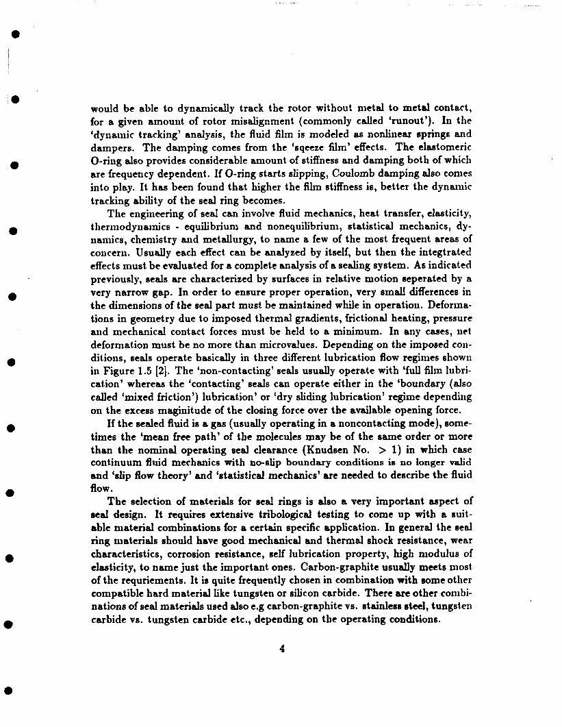
The engiiieering of seal can involve fluid mechanics, heat transfer, elasticity, thermodynamics - equilibrium and nonequilibriuni, statistical mechanics, dy- namics, chemistry and metallurgy, to name a few of the most frequent areas of concern. Usually each effect can be analyzed by itself, but then the integtrated effects must be evaluated for a complete analysis of a sealing system. As indicated previously, seals are characterized by surfaces in relative motion seperated by a very narrow gap. In order to ensure proper operation, very small differences in the dimensions of the seal part must be maintained while in Operation. Deforma- tions in geometry due to imposed thermal gradients, frictional heating, pressure and mechanical contact forces must be held to a minimum. In any cases, net deformation must be no more than microvalues. Depending on the imposed con- ditions, seals operate basically in three different lubrication flow regimes showii in Figure 1.5 [2]. The ‘non-contacting’ seals usually operate with ‘full film lubri- cation’ whereas the ‘contacting’ seals can operate either in the ‘boundary (also called ‘mixed friction’) lubrication’ or ‘dry sliding lubrication’ regime depending on the excess maginitude of the closing force over the available opening force.
If the sealed fluid is a gas (usually operating in a noncontacting mode), some- times the ‘mean free path’ of the molecules may be of the order or more than the nominal operating seal clearance (Knudsen No. > 1) in which case continuum fluid mechanics with no-slip boundary conditions is no longer valid and ‘slip flow theory’ and ‘statistical mechanics’ are needed to describe the fluid flow.
The selection of materials for seal rings is also a very important aspect of seal design. It requires extensive tribological testing to come up with a suit- able material combinations for a certain specific application. In general the seal ring materials should have good mechanical and thermal shock resistance, wear characteristics, corrosion resistance, self lubrication property, high modulus of elasticity, to name just the important ones. Carbon-graphite usually meets most of the requriements. It is quite frequently chosen in combination with some other compatible hard material like tungsten or silicon carbide. There are other coiiibi- nations of seal materials used also e.g carbon-graphite vs. stainless steel, tungsten carbide vs. tungsten carbide etc., depending on the operating conditions.
4

e
l
I
‘ 0
e
0
0
e
e
With all the complexities and highly coupled effects that govern a seal be- havior, it is not a secret that reliable and accurate design analysis for face seals does not exist. Any new seal design must be tested in the laboratory because a prediction of eventual performance is not possible on purely theoritical basis. Again there is a wide variation in performance of seals of “identical design”; a particular seal may fail after few hours whereas another seal belonging to the same class can last for several years or so. It is because of this reason seals are often termed as the ‘most unpredictable machine element’ used in the industry. However a good design and analysis tool is quite useful in evaluating one design against others. This procedure eliminates the need for building expensive proto- types and running time intensive laboratory tests for those designs which seem not so viable at the analysis phase [4]. Also modeling and analysis give more insight into the complex mechanism of seal behavior. Hence there have been quite a good amount of analytical and experimental work done in the face seal area for the last 25 years and efforts are constantly being made by the engineers and scientists to come up with better theoritical models for seal operation. Since it is extremely difficult to perform a comprehensive seal analysis including all different coupled effects, most of the analytical works are focussed on one or two aspects. As of yet some of the individual effects (e.g two phase flow modeling, high Knudsen number flow, mixed friction regime, wear model, nonequilibriuiii effects, to name a few) are not fully understood.
1.1 Liquid Seals A number of investigators have analyzed face seal operating with incompressible liquid for different flow geometries. Etsion have extensively studied the angular misalignment effects on seal performance and stability. A misaligned face seal is shown schematically in Figure 1.6 (111. He obtained a complete system of forces and moments acting on the flexible ring for different values of angular misalignment. These can then be used in a seal dynamic tracking analysis. Etsion [5] observed that any angular misalignment produces a radial force on the flexible ring which in turn causes a radial eccentricity. When this eccentricity is large enough, the pumping of fluid may take place which will affect. the leakage. The seal coning however tends to reduce the magnitude of the radial force [6]. When the pumping takes place in a direction opposite to the hydrostatic pressure drop, it is known as ‘inward pumping’. This phenomenon was studied both analytically and experimentally by Findlay [7,8]. Analysis also showed that a flat outside pressurized seal with angular misalignment has negative axial and angular stiffness [9]. Also the hydrodynamic forces creates a transverse moment.
5

e
e
e
e
e
e
e
e
e
which leads the tilting moment by 90 degrees [lo] that can cause real wobble. However with coning, the stiffnesses might change sign depending on the relation between the angle of tilt and angle of coning [11,12]. For noncavitating flow, the effect of coning reduces the hydrodynamic transverse moment which would improve seal stability. The ‘narrow seal approximation’ is usually made in seal analysis for simplification. With this approximation, circumferential pressure gradient and seal curvature can be neglected. Etsion I131 compared the accurate results from numerical solutions with the approximate results and found that over a radius ratio, ri/re, greater than 0.8, an accuaracy of less than 1% can be obtained and hence most cases this approximation is justified.
For low pressure and/or high speed seals, lubricant cavitation is possible due to hydrodynamic effects. This has been experimentally observed. An interesting work on this subject has been published by Findlay [14]. The lubricant cavi- tation helps generating extra opening force because it prevents the generation of hydrodynamic pressure below the local vapor pressure of the liquid while not restricting the upper bound of the pressure. If cavitation did not occur, the coni- ponents of hydrodynamic force would usually balance out and no net increase over the hydrostatic force would exist, which is not the case for low pressure seals.
Sneck was one of the early investigators who made a very important, contri- bution in the face seal analysis under incompressible flow. He published a series of papers (151 through [20] in ‘68 - ‘69 in which he addressed different aspects af- fecting seal performances e.g angular misalignment, radial eccentricity, tangential waviness, flow turbulence, centrifugal inertia and thermal effects. The centrifu- gal intertia term is included in the misalignment analysis in [15). The centrifugal effects are shown to play a significant role in seal performance at higher speeds. For an outside pressurized sed, the regions of flow field may exist with a radially inward flow along the stationary surface and outward along the rotating one and under certain circumstances, there can be net tero leakage. The existence of such a region is a direct consequence of centrifugal inertial effects. This reverse flow phenomenon has been studied in detail in another paper [16]. The combined effects of misalignment and radial eccentricity is presented in [19]. The resulting leakage component can be inward (opposite to the direction of hydrostatic pres- sure drop) or outward (in the same direction as the hydrostatic pressure drop) depending on the phase angle between the misalignment and radial eccentricity. Sneck also studied eccentricity combined with surface waviness [2O]. Again the direction of leakage component is shown to be dependent on the phase angle. The once per revolution waviness is found to be the main contributor in the pump- ing effect. Turbulent flow is analyzed in [17]. The turbulent nature of the flow is described by an isotropic apparent viscosity model and a power law velocity
6

e
a
a
a
a
0
0
a
0
profile. The misalignment and surface waviness are found to be somewhat less influential with turbulent flow than with laminar flow.
The analysis of face seal is often based on the isothermal flow assumption within the seal clearance. The validity of this assumption is usually argued on the basis that seal faces are often good conductors and hence will not permit large radial temperature variations. But even when the seal operates approxiiiiately isothermally, the temperature within the seal clearance need not necessarily be same as the cavity fluid temperature. An accurate prediction of seal performance requires an accurate evaluation of the fluid viscosity within the clearance space. A general thermal analysis procedure is presented in [18] to estimate the fluid operating temperature level inside the seal. No attempt has been made here to model the heat conduction through the seal rings. The upper and lower bound on the operating temperature are obtained by assuming adiabatic wall condition and zero thermal convection by the fluid respectively. In a recent review paper by Khonsari [21], an extensive survey of literatures pertaining to thermal effects in slider and thrust bearings is presented with summary of important contributors of leading researchers and designers. Since thrust bearings and seals have some similarity, this paper is referred here. One very common assumptions made by the seal analysts is to neglect the fluid temperature variations across the film. But viscosity variation across the lubricant film has been somtimes found to be responsible for generation of an appreciable load. In [21] many papers are cited which indicate the importance of transverse viscosity variation. King and Lauer [22] presented an experimental method by infrared spectroscopy to verify the existence of the temperature gradients through the film.
Pinkus and Lund [23] also considered the effects of centrifugal forces in high speed seals. They mentioned that at the upper limits of laminar conditions, centrifugal forces reduce the load capacity considerably and alter the pattern of the lubricant flow. Koga & Fujita [24] included both the radial and centrifugal inertia terms in their analysis of high pressure water pump seals. They obtained better correlation of the anslytical predictions and experimental results when inertia effects are considered than their previous analysis neglecting these effects.
As mentioned before, the total closing force is supported by hydrostatic and hydrodynamic fluid pressures and often by partial contact of fluid faces (in con- tacting mode of operation only). For moderate to high pressure applications, the hydrostatic force component is predominant over the hydrodynamic component [25]. Since the film thickness is usually very small (of the order of few microns), any local surface deformations due to the interfacial pressure and the angular twist of the seal rings under pressure strongly influence the hydrostatic load suy- port and hence the seal performance [26]. For carbon rings with a relatively low modulus of elasticity, the distortions can easily be of the same order of magni-
7

e
a
e
e
e
a
0
a
a
tude as the nominal clearance of the seal. Thermal distorotions can also occur due to both axial and radial temperature gradients in the seal rings caused by the frictional heat generated at the interface. Any radial taper in the direction of the flow changes the hydrostatic pressure distribution and the film stiffness. A diverging seals (in the leakage direction) exhibits a negative axial stiffness which may lead to seal collapse and high wear. With the availability of fast computers and necessary softwares, the finite element (FE) analysis is commonly used for accurate predictions of pressure deformation and thermal distortion. A very iniportant series of papers (27,28,29, to mention a few of them] have been published over the years by Metcalfe and his research staff at the Atomic En- ergy of Canada Ltd. (AECL) describing these analytical techniques. Analysis of seal-ring deflections due to applied pressure loadings, to thermal effects and to coloumb friction between components is described in [28]. The deflection sen- sitivity of sed components are expressed as ‘inflence coefficients’, evaluted with finite element analysis. He noted that coloumb friction gives rise to undesirable perforiiiance hysterisis when operating conditions are changed. The correlation of experimental results and theoritical predictions is presented in [29]. Salant [30] present-ed an analytical model of a generalized mechanical seal incorporat- ing the fluid dynamics of the film and the mechanical and thermal distortions of various sed components. He utilized the concept of ‘influence coefficients’ used in (281. He found that the hydrodynamic forces due to waviness, roughness, misalignment and eccentricity produce insignificant opening force effects in coin- parison with the available closing force for high pressure seals. The hydrostatic pressure is responsipble in carrying the most of the applied load. Hence the face deformation, particularly ‘coning’ is the most likely controlling mechanism for load support for these kind of seals. Based on this idea, Salant presented a novel design of an electronically controlled seal in [31). A microcomputer based real time control system and electro-mechanical actuator dynamically adjust the seal
coning and hence the film thickness, based on information received from the sta- tor which monitors conditions of the film. This arrangement. can greatly reduce face contact while limiting leakage by continuously optimizing film thickness. This would lead to a reduction in seal damage and wear and increase in seal life. Li [32] presented a finite difference heat conduction model for calculating the temperature distribution in the seal rings and resulting deformations. He coli- sidered one dimensional toroidal deformation model in which the seal rings will preserve the geometry of the radial crosssection after deformations. Doust and Parmar [33,34] numerically analyzed axisymmetric distortions due to pressure and thermal effects using ‘boundary integral element’ (BIE) method and corre- lated the results with the experimental measure1iient.s. They remarked that the BIE method is substantially more economical in terms of both computing time
8

a
e
a
e
0
a
and storage than FE for the same lave1 of accuracy. The main object of their test was to measure the fluid film geometry using capacitance type proximity probe, as a furictioii of pressure. The sealant pressure and thermal effects essentially caused toroidal rotation of the faces for those seals used by them. This rotation rate was found to be fairly insensitive to the interface pressure profile. They also observed hysterisis effect due to secondary seal friction. In a recent payer (351 by them, the effects of thermoelastic transients have been presented. The transient thermal distortion can be an order of magnitude greater than that at steady state. Transient response is worse for a shorter section than a longer one, although the time to reach steady state can be more than an hour for a long seal component. This is an interesting work since field surveys do suggest that transient operations can be more detrimental to the seal life than steady state running.
There are not as much work done in the ‘mixed-friction lubrication’ area for the contacting seals as in the ‘full-film lubrication’ regime for the noncontart- ing mode of operation, mentioned so far. The obstacle to further advancement in contacting seal technology is that relationship between controllable design parameters and performance parameters are not well understood. Lebeck has published a number of papers [36,37,38,91] on ‘mixed-friction’ flow modeling and contacting seal analysis. He developed a model [36] which takes into account load sharing between mechanical and fluid hydrostatic pressure. The effect of wear is also modeled in order to predict how the radial profile alters and influences the hydrostatic pressure distribution with time. The experimental evaluation of the model is reported in [37]. In a contacting seal operation, an unstable phe- noinenon is observed by a number of researchers, including Kenndy and Grim [39], in which case a very slight amount of initial waviness on 8eal faces grows during sed operation. When this unstable condition, called ‘thermoelastic in- stability’ occurs in an operating face sed, the consequences - nonuniform wear,
accentuated waviness, and high localized stresses and temperatures - can be very detrimental to eeal performances. Kiryu et al. [40,41] reported the generation of a “ringing” sound in a contacting water pump seal. They attributed this phe- nomenon to self-excited vibration due to ‘stick-slip’ action, caused by transferring from fluid lubrication to dry sliding condition. Vibration mode in ringing sound generation is found to be mainly caused by the torsional and axial vibrations of the rotating shaft system.
The preivious investigations, mentioned so far, are mainly based on steady state analyses. However, the angular misalignment is inevitably present 011 the rotating ring which introduces a dynamic forcing function on the flexibly mounted stator. Hence the ability of the stator ring to track the rotor in B controlled man- ner is of great importance for safe seal operation and as the demand for higher
9

e
0
0
e
e
e
0
operating speeds in rotating machinary increases, the importance of seal dynam- ics becomes more and more evident. A several researchers namely Etsion, Green, Metcalfe and others have addressed this issue analytically and experimentally in (421 through [55] A review of face seal dynamics covering the literature until 1981 is presented in [50].
The flexibly mounted stator has basically three major degrees of freedom - axial and angular about any two orthogonal diameters. The twisting motion about axial direction is prevented by antirotation locks. If the radial stiffness of the O-ring secondary seal is low, which is usually not the case, then the stator can also move in the two perpendicular radial directions. The rotor transmits its angular motion to the stator via the thin fluid film seperating the two seal rings. For a given forcing function, the response of the stator depends on its own inertia, the stiffness and damping of the fluid film and the elastomeric O-ring. The fluid film damping comes from the squeeze effects. In some cases the squeeze effects are an order of magnitude higher than the combined hydrodynamic and hydrostatic effects and hence play an important role in dynamic behavior of face seals. The stiffness and damping coefficients of the fluid film ,both direct and cross-coupled, in the three major d.0.f are calculated in [44,51] based on small perturbation theory. It has been found that narrower the seal, the less is the damping coefficients and at very small tilt, translational and rotational direct damping coefficients are an order of magnitude higher than the cross- coupled ones. The damping and stiffness characteristics of elastomeric O-ring are dependent on the amplitude and freqency of excitation and amount of sqeeze. The experimental determination of the O-ring dynamic properties are presented in (54,56,57]. With a large rotor misalignment, the stator response is usually large and sometimes sliding takes place at the O-ring interfaces and then the Coloumb friction becomes important.
Dynamic analysis in [45,46,48,52] based on linearized small perturbation the- ory revealed three modes of operation : a stable mode in which a misaligned rotor is synchronously tracked by the flexibly mounted stator; a transition mode in which half-frequency wobble of the stator is superimposed on the previous synchronous tracking mode; and an unstable mode characterized by uncontrolled vibration of the stator, eventually causing failure. In the unstable mode, a seal will fail even with zero rotor runout. For low and moderate speeds, the stable mode seems to predominate. The stator tilt, however, differs from that of the rotor both in magnitude and direction. The difference and phase shift between two tilts result in relative angular misalignment between the rotor and stator. If this relative misalignment becomes too large, seal failure due to excessive leakage or even rubbing contact can occur even though the seal is dynamically stable. In [55], the complete nonlinear equations of motion of the stator are solved numeri-
10

a
e
a
e
e
e
a
cally. The assembly tolerances in the form of initial stator misalignment and the dynamic properties of the elastomeric O-ring are accounted for in the analysis. Both statbility threshold and steady-state response of the stator are investgated. In general, it was found that the critical shaft speed corresponding to stability threshold is quite high. Hence, the dynamic stability should not be a probleiii in the majority of noiicontacting seals. A more practical problem is the steady- state dynamic response of the stator resulting from rotor runout and assembly tolerances. The results of the numerical analysis were compared with those of the previous s n i d perturbation analysis that provides much simpler closed foriii aiialytical solution. Very good correlation was found between the two analyses for most cases of practical applications.
Etsion and Burton [43] observed self-exicted oscillations of seal ring in the form of precession and nutation. The wobble frequency was measured to be about 43% of the rotational frequency. Metcalfe [49] analyzed and tested a well- aligned face seal. He found that if the balance ratio is below a certain critical d u e the seal becomes hydrostatically unstable. If the elastomer stiffness in the tilting mode is insufficient to overcome this hydrostatic instability, the stator will exhibit wobble motion. The precession rate is theoriticcrlly found to be half the shaft speed if elastomer darnping is insignificant (pure "whirl") and progressively slower as damping increases. Etsion presented an experimental observation of the dynamic behavior of face seals in [53]. The forced response of the stator due to the rotor runout was monitored by means of three proximity probes. It was found that both the stator tilt and its phase shift with respect to rotor tilt axe t h e dependent and vary synchronously with the rotor rotation. The time variation is attributed to the presence of two components of stator tilt. One coinponent is fixed in magnitude but tracks the rotor tilt. The other componeiit is fixed both in magnitude and direction and is due to nonaxisymmetric effects in the flexible support of the stator. As a result, the relative misalignment between the stator and rotor was found to be time dependent. The dynamically unstable seal behavior was also observed. At low supply pressure which means low film stiffness, results showed a sinusoidal perturbation at double the shaft frequency superimposed on the initial wobble due to angular misalignment. In the previous experiments, perturbation was always observed at half rather than double the shaft rotation rate. As the supply pressure was increased, this double frequency stable to unstable transition became a half-frequency transition instead. This higher frequency instability was not fully understood.
e
11
e

0 , l
0
‘0
0
0
0
0
0
0
0
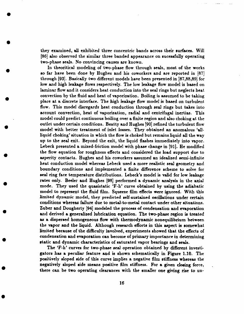
1.2 Gas Seals The efforts on gas seal development started little later than the liquid seals atid the works in this area are not equally numerous. In earlier time, the machineries having gases as working fluids, like gas compressors, used and some of them still use liquid seals with an oil-buffered arrangements. The reason for this that proper technology was not available to insure non-contacting mode of operation, which is absolutely essential for gas seals because of the poor lubrication properties and high speed of operation. The oil is kept at a pressure little higher than the sealed gas to ensure that only oil leakage could take place into the gas and seal would never run dry. In addition oil also leaks to atmosphere through another seal. Apart from the cost factor (about two orders of magnitude higher than the corresponding single phase seals), this design has some major disadvantages in terms of auxiliary equipments and space requirements. Also since product contamination with just a small amount of buffer fluid may create enough prob- lems, contacting liquid seals are typically used, which have inherently low and unpredictable life. Hence the need for a noncontacting sed development did arise for sealing gaseous fliuds. Although the basic concepts are the same, the main difference between the liquid and gas seal analyses is that the governing equations describing the gas flow are nonlinear because of compressibility effects and inclusion of flow inertia, which are too important to ignore sometimes. The flow is often turbulent and choking may occur at the outlet. Also under the con- ditions of high velocity, the entrance loss effects cannot be neglected. The gas seals should also operate with a high film stiffness in order to have good dynamic tracking ability to prevent contact. As mentioned before, the pressure within the fluid filii1 are generated hydrodynamically by the relative motion between uneven sealing surfaces and hydrostatically by fiictional pressure drop through the seal. The hydrodynamic action ceases when the motion stops. Also there is no hydrodynamic pressure generation with parallel faces. To a limited extent all seal possess some hydrodynamic characteristics as a consequence of geometric imperfections and unplanned unevenness such as inherent or pressure induced circumferential waviness or micro-irregularities. These effects are usually quite rmall. The hydrostatic effects alone impart aero stiffness to a seal unless there is a radial coning in the flow direction. Because of these facts, some consious efforts have been made to enhance the hydrodynamic action rather than rely on chance variation, by having planned uneven hydrodynamic patterns on the real surfaces. Some of the commonly used patterns are spiral groove, Rayleigli- step pads, radial grooves, as shown in Figure 1.7 [58]. These are called ‘hybrid’ seals. The hydronsmic pattern is followed by a seal dam which offers restrictions to the fluid flow and most of the pressure drop takes place there. Because of
12

e
e
e
e
e
*
e
e
e
hydrodynanlic action, there are some areas of higher pressure and other areas with lower pressure. Figure 1.8 [58] shows the elevated pressure areas on the two seals. Figure 1.9 shows the components of ‘F-h’ curves for the hydrodynamic and the hydrostatic sections of a ‘hybrid’ seal with Rayleigh-step pads, analytically obtained by Shapiro [59]. The two curves niust be combined to get the net film characteristics for the seal under consideration. No angular misalignment effects is considered in this analysis. It is evident from this figure that the hydrodynanlic action indeed imparts a very high film stiffness, partcularly at small clearances and prevents the seal faces from touching each other. The closing force is usu- ally chosen so that the seal operates near the high stiffness region. Also it is seen that hydrostatic stiffness is almost zero and hence it does not contribute to the seal stability, although it may carry a major part of the closing force. Ex- perinients performed by Ludwig [60] showed that seals with hydrodynamic pads outperformed the conventional seals used in sniall gas turbines.
Some of the important researches on gas seals are documented in (591 through [72]. Cheng [61] analyzed few different designs and found that the spiral groove design gives higher stiffness than Rayleigh-step pad one. This same conclusion was also drawn by Sedy (581. He also brought out an interesting point. As men- tioned before, most of the gas expansion takes place over the dam. The cooling effect associated with the expansion is sometimes several times more than the heating effect due to viscous dissipation. The net effect is the cooling of the gas near the dam and consequently a considerable amount of heat conduction takes place from the seal rings to the gas in the vicinity of the dam. The tempera- ture gradient, thus set up in seal rings, tends to distort the seal face in a way to produce a divergent flow passage which has an unstable effect and sometime causes seal contact at the outer diameter. Sedy suggested a wider dam design to overcome this problem because a wider dam would cause a higher heat genera- tion which in effect tends to neutralize the cooling effect due to gas expansion. Zuk [64] presented a quasi one-dimensional analysis for the flow of gas through seals. This model includes fluid inertia and entrance loses, in addition to viscous friction which is accounted for by a friction factor. Subsonic and choked flow con- ditions have been predicted and analyzed. This model is valid for both lanlinar and turbulent flows. Hsing and Caxraro (741 used an efficient algoritllim based on fourth order Runge-Kutta with adaptive step size to solve the same govern- ing differential equation. Shapiro [59] performed both steady state and dyiiaiiiic analyses of a gas seal for jet engines. The seal dynaniic response was found as a function of rotor misalignment and secondary seal friction. He theoritically obtained superharmonic response, about four times the shaft RPM, which has been confirmed experimentally. This phenomenon has been attributed to nonlin- ear characteristics of the O-ring. The flexible ring is found to loose its tracking
13
e
e
a
0
0
0
0
ability if tlie rotor runout or the friction force is too large. If tlie gas inside a seal is at sufficiently low pressure, the molecular nieaii
free path can become comparable to the film thickness. The fluid subjected to this coiiditioii does not behave entirely as a continuum fluid but rather exhibits some characteristics of molecular chaos. One may also expect to encounter these effects in regions having very sharp gradients of fluid properties such that these properties change appreciably in the space of a few mean free paths, regardless of whether or not the absolute density of the gas flow is especially low. The diiiieiisioiiless ration, A / h (Knudsen number), is a measure of tlie degree of rar- efaction. Wlien this ratio is large, the flow phenomena are mostly dictated by tlie molecular-surface interaction. This class of fluid flow is defined as “free-molecular flow”. For flows in which the d u e of Knudsen number is small, typically 0.01 - < X / h - 0.1, but not negligible as those in continuum mechanics, sotlie depar- tures from the usual contiiiuum flow phenomena may be expected to occur. The layer of gas iiiimediately adjacent to the solid surface no longer assullies tlie same kinematic condition as the solid boundaries but has a finite relative “slip veloc- ity” aiid hence produces an apparent diminution in fluid viscosity. This is called the “slip-Row regime”.
The few research works covering these non-continuum effects on lubrication are documented in 173) through [78]. Hsing and Malanoski [74] found that if lubricant is one of tlie gases having a large molecular mean free path, such as Helium, Neon or Hydrogen, the slip-flow phenomena could contribute substantial reduction in the performance of a thrust bearings, which is quite similar to face seals. Galis [75] derived a slip flow lubrication equation for an arbitrary Knudsen nuiiiber from kinetic theory. Fukui and Kaneko [76] developed a more accurate generalized lubrication equation based on linearized Boltzmann’s equation. The experiiiiental results obtained by them [77) agreed well with their numerical re- sults. Kubo et al. presented a finite element solution of the Boltzmann’s equation in [78).
1.3 Two-phase Seals When liquid is sealed at temperature Iiiglier than its saturation temperature at tlie outlet pressure, it flashes inside the seal due to the pressure drop and/or the viscous heat dissipation. Typical examples of applications where such two-phase flow iiiay be encountered are light hydrocarbons in petroleuiii refineries, hot water iii boiler feed pumps and reactor coolant pumps, and cryogenic fluids like liquid oxygen aiid hydrogen (LOX / LH2) in rocket turbopumps. The two-phase seals generally exhibit more erratic behavior than their single phase counterparts.
14
e

e
0
I e
0
a
a
e
The seals also have more stringent requirements in their performances because of severity in applications. As for example, light hydrcarbons are potentidy flammable and explosive and hence certainly dangerous if allowed to leak. Since these hydrocarbons in gaseous phase are heavier than air, they usually form a thick dense cloud on the ground around the source. It constitutes a severe hazard (791. In LOX / LH2 turbopumps, any seal failure due to excessive leakage can be, needless to say, extremely dangerous. Actually the face seals in the turbopumps failed repeatedly on the NASA test pads until they have been replaced wit.11 annular seals. Although annular seals are safe in operation, they allow very high leakage and did cost NASA millions of dollars worth of fuels during each testing and launching operation. At a later date, the face seals have been adopted sucessfully in the LOX / LH2 turbopumps for the Japanese H-1 rocket (801. Two-phase seal operation is also encountered in boiler feed pumps. It has been estimated that the boiler feed pump outages alone cost power companies several hundred million dollars each year in lost power revenues. It is believed that a high percentage of these problems is related to seal failures [97]. The reactor coolant pump (RCP) seals can also experience change of phase of the sealed fluid during station blackout conditions and exhibit excessive leakage. Failure of these precision components may result in a small loss of coolant accident (LOCA) in nuclear reactors [82].
Because of the severity of applications, the two-phase operation mechanisnis are to be better understood in order to conie up with a suitable design. The research works done in this area are reported in [79] through [102]. An inter- esting earlier papers on this subject was published by Orcutt (831. He used a quartz runner to permit visual observation of the seal interface during operation. The experimental observations indicated the existence of a multiple phase film, charcterized by two large scale regions. The first region adjacent to the seal cav- ity was occupied almost entirely by water. The second annular region extends from the atmospheric edge of the interface to a semi-stable boundary with the liquid-filled region. This region was occupied by a mixture of liquid and vapor. The boundary moved towards the edge adjacent to the sed cavity with the rise in liquid and seal surface temperatures. Unstable operation was encountered with visible leakage as the cavity fluid temperature was increased. More than a decade later, Harrison and Watkins [84] and Wallace [79) reported a similar unstable two-phase operation with light petroleum products at elevated temper- ature. Under the unstable operation, the fluid Aim periodically broke down and reformed with violent fluctuations in torque. Seals showed both audible (while in operation) and visible (when taken apart) signs of distress. Seal operation was, however, stable at lower temperature. Barnard and Weir [85] reported seals oper- ating sucessfully with no visible leakage because of vaporization. The seal faces,
.
15
e
a
0
0
0
a
0
a
they examined, all exhibited three concentric bands across their surfaces. Will [86] also observed the similar three banded appearance on sucessfdy operating two-phase seals. No convincing causes are known.
In theoritical modeling of two-phase flow through seals, most of the works so far have been done by Hughes and his coworkers and are reported in [87] through (931. Basically two different models have been presented in [87,88,89] for low and high leakage flows respectively. The low leakage flow model is based on laminar flow and it considers heat conduction into the seal rings but neglects heat convection by the fluid and heat of vaporization. Boiling is assumed to be taking place at a discrete interface. The high leakage flow model is based on turbulent flow. This model disregards heat conduction through seal rings but takes into account convection, heat of vaporization, radial and centrifugal inertias. This model could predict continuous boiling over a finite region and also choking at. the outlet under certain conditions. Beatty and Hughes [go] refined the turbulent flow model with better treatment of inlet losses. They obtained an anomalous ‘d- liquid choking’ situation in which the flow is choked but remains liquid all the way up to the seal exit. Beyond the exit, the liquid flashes immediately into vapor. kbeck presented a mixed-friction model with phase change in [91]. He modified the flow equation for roughness effects and considered the load support due to asperity contacts. Hughes and his coworkers assumed an idealized semi-infinite heat conduction model whereas Lebeck used a more realistic seal geometry and boundary conditions and implemented a finite difference scheme to solve for seal ring face temperature distributions. Lebeck’s model is valid for low leakage rates only. Beeler and Hughes (981 performed a dynamic analysis in the axial mode. They used the quasistatic ‘F-h’ curve obtained by using the adiabatic model to represent the fluid h. Squeeze film effects were ignored. With this limited dynamic model, they predicted self-sustained oscillations under certain conditions whereas failure due to metal-to-metal contact under other situations. Zuber and Dougherty [94] modeled the process of condensation and evaporation and derived a generalized lubrication equation. The two-phase region is treated as a dispersed homogeneous flow with thermodynamic nonequilibrium between the vapor and the liquid. Although research efforts in this aspect is somewhat limited because of the difficulty involved, experiinents showed that the effects of condensation and evaporation can become of primary importance in determining static and dynamic characteristics of saturated vapor bearings and seals.
The ‘F-h’ curves for two-phase seal operation obtained by different invest& gators has a peculiar feature and is shown schematically in Figure 1.10. The positively sloped side of this curve implies a negative film stiffness whereas the negatively sloped side means positive film stiffness. For a given dosing force, there can be two operating clearances with the smaller one giving rise to un-
.
16

0
0
a
0
stable Operation and the larger one stable. Vaporization also seems to inhibit leakage.
The two models for two-phase seal operation, developed by Beeler and Beatty [104,112], work reasonably well at the two extremes - very low leakage rates with convection neglected and very high leakage rates with conduction neglected. Both models break down as soon as the effect neglected in the respective model begins to become important. In actuality, most twephase seal operations take place in the intermediate leakage range when both conduction and convection are important. A preliminary model is developed here to bridge the gap between the two previous models. This model, known as the ‘Film Coefficient Model’, is valid over the entire laminar flow regime unlike the earlier model developed by Beeler which only worked at the very low leakage rate end. The new model considers both conduction and convection and allows continuous boiling over an extended region whereas the earlier model which neglects convection always forces a discrete boiling interface and exhibits numerical instability as soon as leakage rate starts becoming little higher. With the inclusion of turbulence axid radial iritertia effects, the applicability of the ‘Filni Coefficient Model’ can be extended to high leakage rate end with the ability to predict choking. Hence this model has the potential for describing the seal behavior over the entire range of possible leakage rates - low to high.
Another simplified and semi-analytical model, known as ‘Isothermal Model’, has also been developed for low leakage rates. This is based on the model devel- oped by Beeler. The assumptions of isothermal condition along the seal interface and ideal gas behavior of the vapor permit closed form solutions which may be used for preliminary design and analysis. However, to obtain more accurate and realistic description, the ‘Film Coefficient Model’ may be used.
Under certain two-phase operation, seals seem to exhibit self-sustained os- cillations even when all the applied conditions remain quite steady. This was observed as &symmetric fluctuations in the film thickness accompanied with pe- riodic interface temperature variations. The ‘Film Coefficient’ and the ‘Isother- mal’ models are for steady state analysis and none of them can describe this anomalous behavior. A preliminary transient heat conduction model has been presented here which might help building a comprehensive model to predict the oscillatory seal behavior.
A review of the works done in the single-phase seal area has been presented here because some of the ideas and concepts can be used in modeling two-phase seal operation. The analysis of two-phase flow in face seals is very complex, and a good amount of further research is required to understand a seal behavior. The author hopes that the work reported here would give some directions to the future efforts.
17

0
0
0
Figure 1.1 : Classificat.ion Diagram - hidustrial Sealing Devices
0
a
Figure 1.2: Schematic Diagram of a Face Seal
18

0 I
0 SEAL SEAT
SEALED FLUID
a
a
0 Figure 1.3: Force Diagraiii on a SI at or
e
19

OIYIGINAL PAGE I§ OF POOR QUALI?"Y:
-#-
Figure 1.4: Possible Primary-Seal Geometries
Figure 1.5: Seal Lubrication Models
20
e

0
0
ORIGINAI; PAGE IS OF POOR QUALITY
section €1-8 in I
a
Figure 1.6: Face Seal with Angular Misalignment and Coning
21
a
0
0
SPIRAL GROOVE
Figure 1 .i: Hydrodynaniic Pat.t.erns on Face Seals
RAYLEIGH STEP PAD
Figure 1.8: Hydrodyiiaiiiic Pressure C;eiierat.ion
22

0
0
160.
140 -
i
0 0.2 0.4 0.6 0.8 1.0
40 t 0 3 J
- 20 I- LL
AXIAL CLEARANCE (MILS)
HY OROOYNAM I C SEC TlON
'*O t L A 0 0.2 0.4 0.6 0.8 1
160
AXIAL CLEARANCE (MILS)
HY O R 0 STAT I C SECT I ON
3
Figure 1.9: Hybrid Gas Seal F-h Curves - Hydrodynaiiiic and Hydrostatic Com- ponents
23

w 0 a
FILM THICKNESS
Figure 1.10: Seal F-h Curves for Two-phase Operation
24