CARLO GAVAZZI · CARLO GAVAZZI Automation Components UDM 35/40 Digital Panel Meter Programming...
22
CARLO GAVAZZI Automation Components UDM 35/40 Digital Panel Meter Programming Guide
Transcript of CARLO GAVAZZI · CARLO GAVAZZI Automation Components UDM 35/40 Digital Panel Meter Programming...
CARLO GAVAZZI A u t o m a t i o n C o m p o n e n t s
UDM 35/40 Digital Panel Meter
Programming Guide
UDM 35/40 PANEL METER USER MANUAL
1
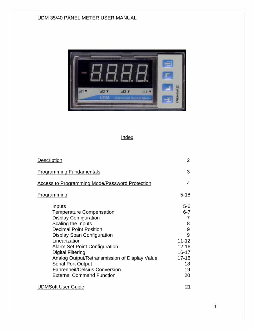
Index
Description 2 Programming Fundamentals 3 Access to Programming Mode/Password Protection 4 Programming 5-18 Inputs 5-6 Temperature Compensation 6-7 Display Configuration 7 Scaling the Inputs 8 Decimal Point Position 9 Display Span Configuration 9 Linearization 11-12 Alarm Set Point Configuration 12-16 Digital Filtering 16-17 Analog Output/Retransmission of Display Value 17-18 Serial Port Output 18 Fahrenheit/Celsius Conversion 19 External Command Function 20 UDMSoft User Guide 21
UDM 35/40 PANEL METER USER MANUAL
2
UDM Description The UDM 35/40 series is a universal Digital Panel Meter that has been developed to meet the most advanced application requirements. The UDM 35 offers:
• Quick assembly and maintenance using plug & play modules • Quick & easy parameter programming and parameter cloning to
other UDMs by means of UDMSoft or PC HyperTerminal • Powerful variable control by means of up to four (4) alarm outputs • Alarms can be up-down functions with automatic reset, up-down
with manual reset, and down alarm with disable function at power-up.
The UDM 40 offers the same features as the UDM 35, with the following additional benefits:
• Display color adaptable to Green, Red and Amber • Management of non-linear signals using the available 16-point
linearization capability • “Alarm status at a glance” using a sequence of display colors that
can be programmed by the user
UDM 35/40 PANEL METER USER MANUAL
3
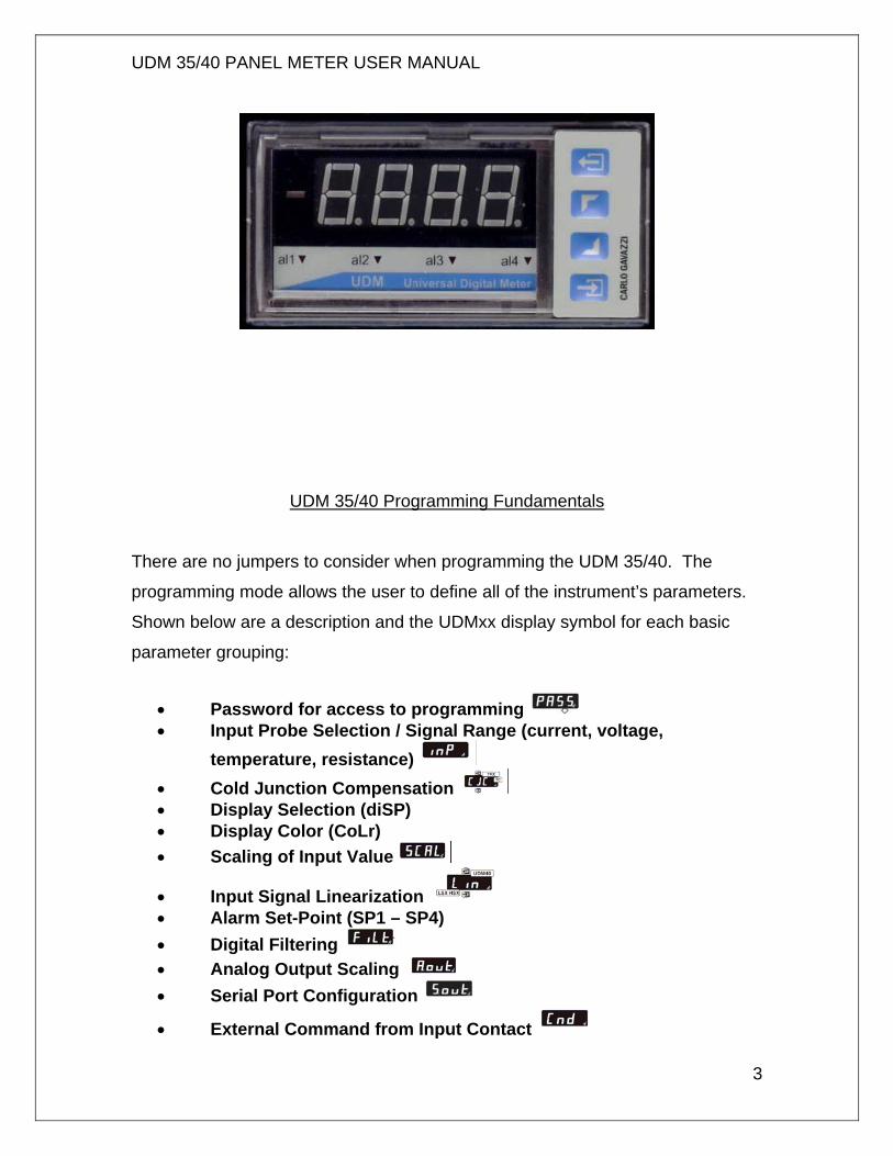
UDM 35/40 Programming Fundamentals There are no jumpers to consider when programming the UDM 35/40. The
programming mode allows the user to define all of the instrument’s parameters.
Shown below are a description and the UDMxx display symbol for each basic
parameter grouping:
• Password for access to programming • Input Probe Selection / Signal Range (current, voltage,
temperature, resistance) • Cold Junction Compensation • Display Selection (diSP) • Display Color (CoLr) • Scaling of Input Value
• Input Signal Linearization • Alarm Set-Point (SP1 – SP4) • Digital Filtering • Analog Output Scaling • Serial Port Configuration
• External Command from Input Contact
UDM 35/40 PANEL METER USER MANUAL
4
Access to Programming Mode
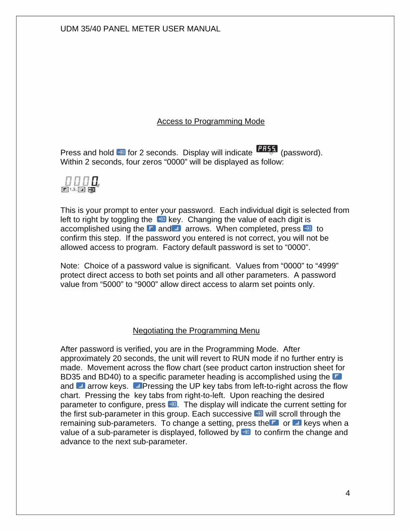
Press and hold for 2 seconds. Display will indicate (password). Within 2 seconds, four zeros “0000” will be displayed as follow:
This is your prompt to enter your password. Each individual digit is selected from left to right by toggling the key. Changing the value of each digit is accomplished using the and arrows. When completed, press to confirm this step. If the password you entered is not correct, you will not be allowed access to program. Factory default password is set to “0000”. Note: Choice of a password value is significant. Values from “0000” to “4999” protect direct access to both set points and all other parameters. A password value from “5000” to “9000” allow direct access to alarm set points only.
Negotiating the Programming Menu
After password is verified, you are in the Programming Mode. After approximately 20 seconds, the unit will revert to RUN mode if no further entry is made. Movement across the flow chart (see product carton instruction sheet for BD35 and BD40) to a specific parameter heading is accomplished using the and arrow keys. Pressing the UP key tabs from left-to-right across the flow chart. Pressing the key tabs from right-to-left. Upon reaching the desired parameter to configure, press . The display will indicate the current setting for the first sub-parameter in this group. Each successive will scroll through the remaining sub-parameters. To change a setting, press the or keys when a value of a sub-parameter is displayed, followed by to confirm the change and advance to the next sub-parameter.
UDM 35/40 PANEL METER USER MANUAL
5
Programming the Input Modules
Press and hold for 2 seconds. Display will indicate PASS (password). Within 2 seconds, four zeros “0000” will be displayed. This is your prompt to enter your password. If zero “0000” is your password, simply press to confirm. You have approximately 20 seconds to begin programming before the unit reverts back to run mode. (To enter a unique password, see Access to Programming Mode, above.) Input Selection
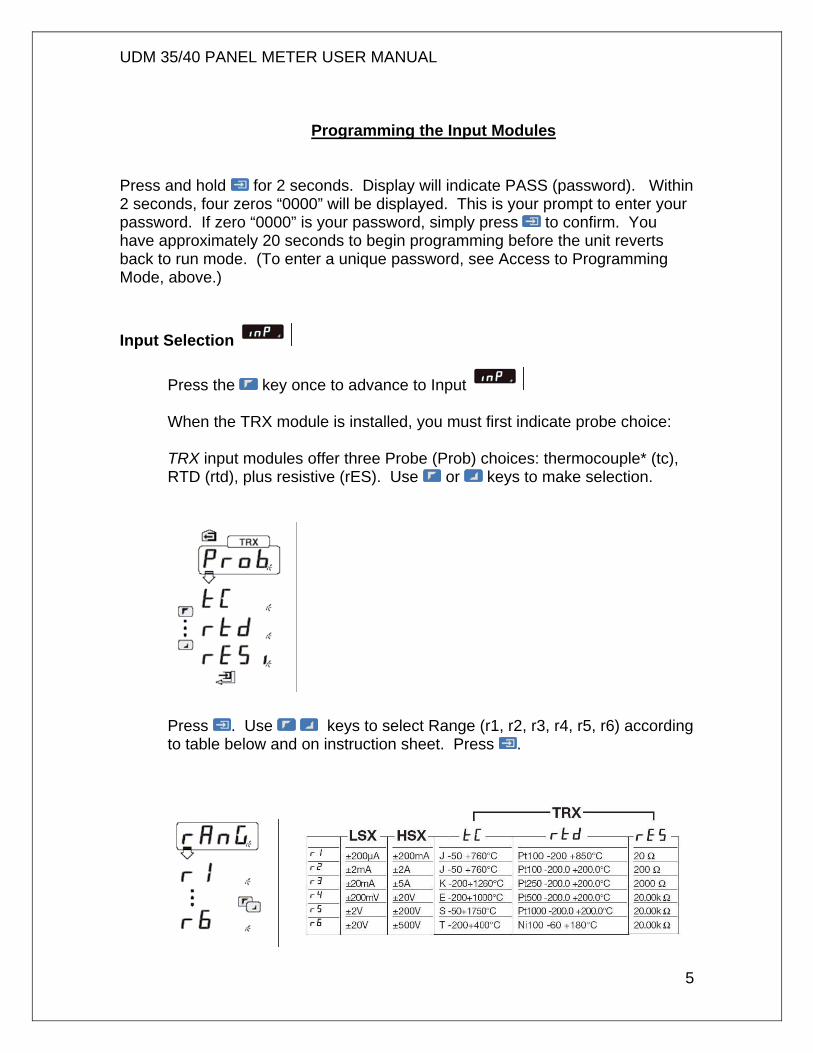
Press the key once to advance to Input When the TRX module is installed, you must first indicate probe choice: TRX input modules offer three Probe (Prob) choices: thermocouple* (tc), RTD (rtd), plus resistive (rES). Use or keys to make selection.
Press . Use keys to select Range (r1, r2, r3, r4, r5, r6) according to table below and on instruction sheet. Press .
UDM 35/40 PANEL METER USER MANUAL
6
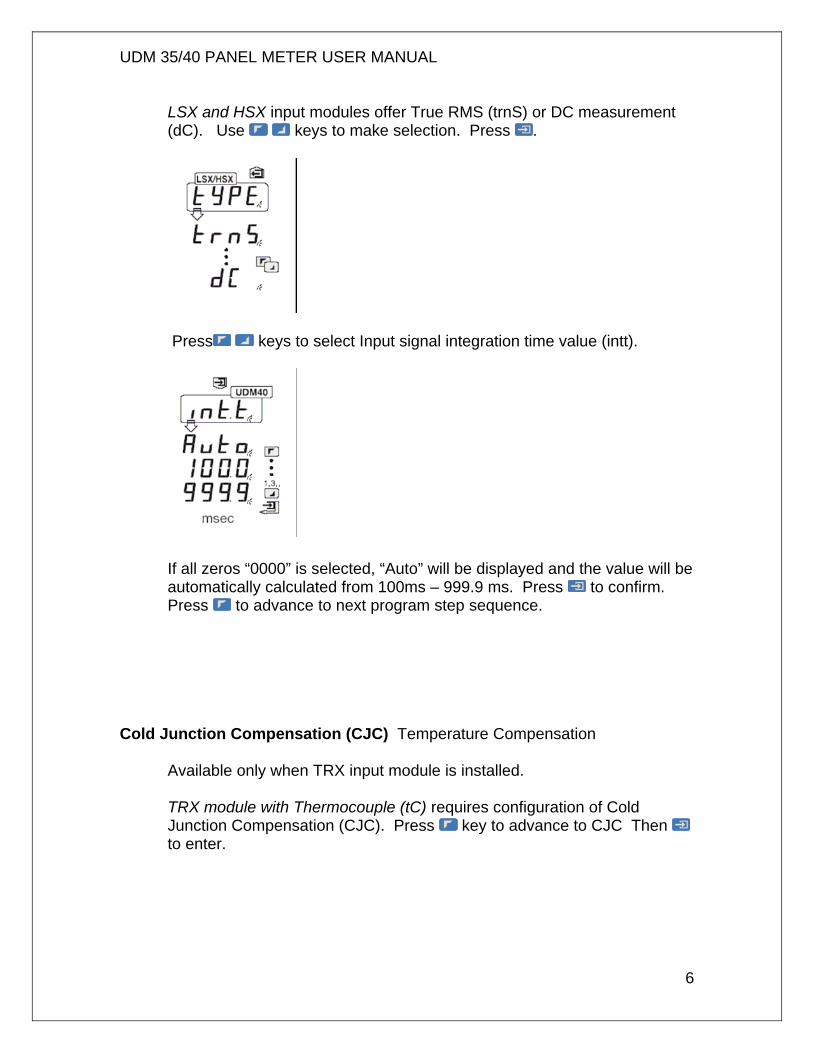
LSX and HSX input modules offer True RMS (trnS) or DC measurement (dC). Use keys to make selection. Press .
Press keys to select Input signal integration time value (intt).
If all zeros “0000” is selected, “Auto” will be displayed and the value will be automatically calculated from 100ms – 999.9 ms. Press to confirm. Press to advance to next program step sequence.
Cold Junction Compensation (CJC) Temperature Compensation Available only when TRX input module is installed.
TRX module with Thermocouple (tC) requires configuration of Cold Junction Compensation (CJC). Press key to advance to CJC Then to enter.
UDM 35/40 PANEL METER USER MANUAL
7
Press key to select Auto (Auto). Press to confirm. . Press to advance to next program step sequence. Manual compensation should only be used in special applications. Consult factory.
Configuring the Display (diSP) UDM35 only
UDM 35 (BD35) base unit displays may be configured as 3 ½ digit (1999) or 3 digit + dummy zero (9990). When “diSP” is displayed, press . Then press keys to make selection. Press to confirm. Press to advance to next program step sequence.
Selection of Display Color (CoLr) UDM40 only
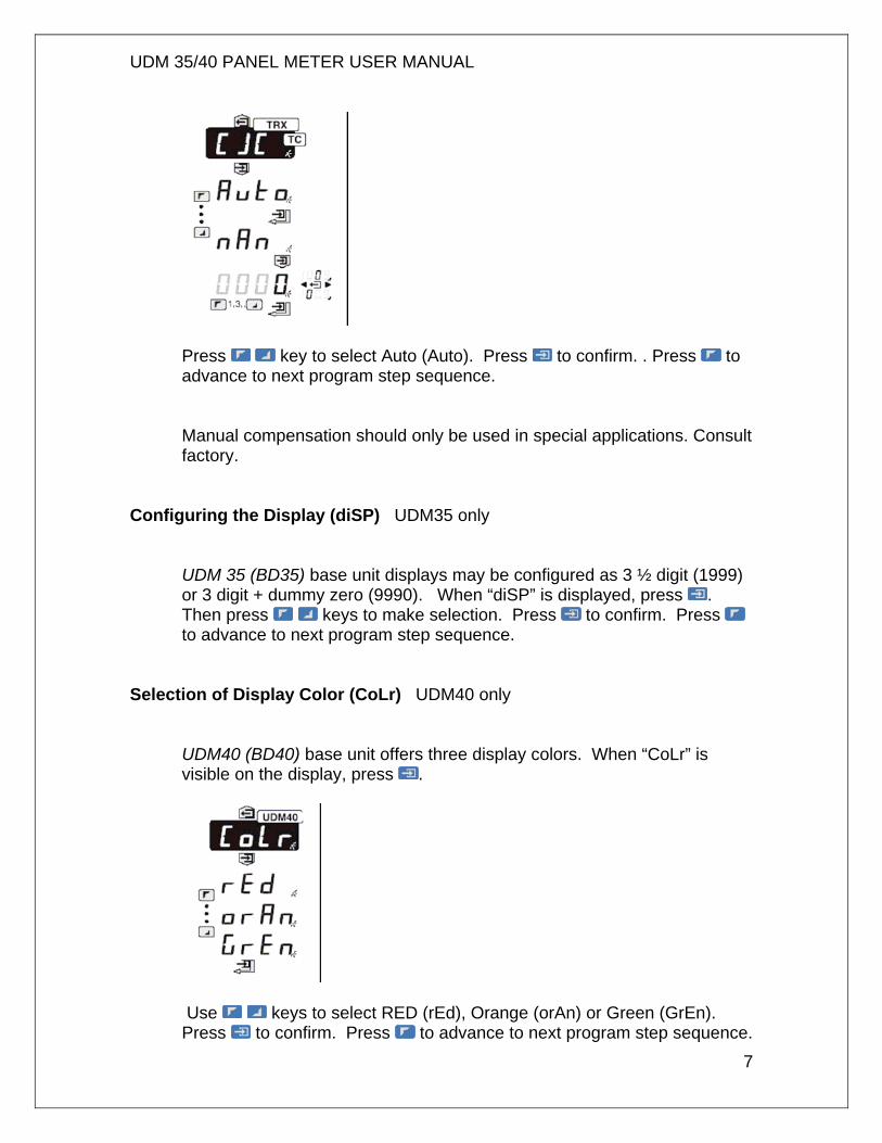
UDM40 (BD40) base unit offers three display colors. When “CoLr” is visible on the display, press .
Use keys to select RED (rEd), Orange (orAn) or Green (GrEn). Press to confirm. Press to advance to next program step sequence.
UDM 35/40 PANEL METER USER MANUAL
8
Scaling the Inputs
When is displayed, access is available for configuring the electrical input range, the decimal point position and display span as follows:
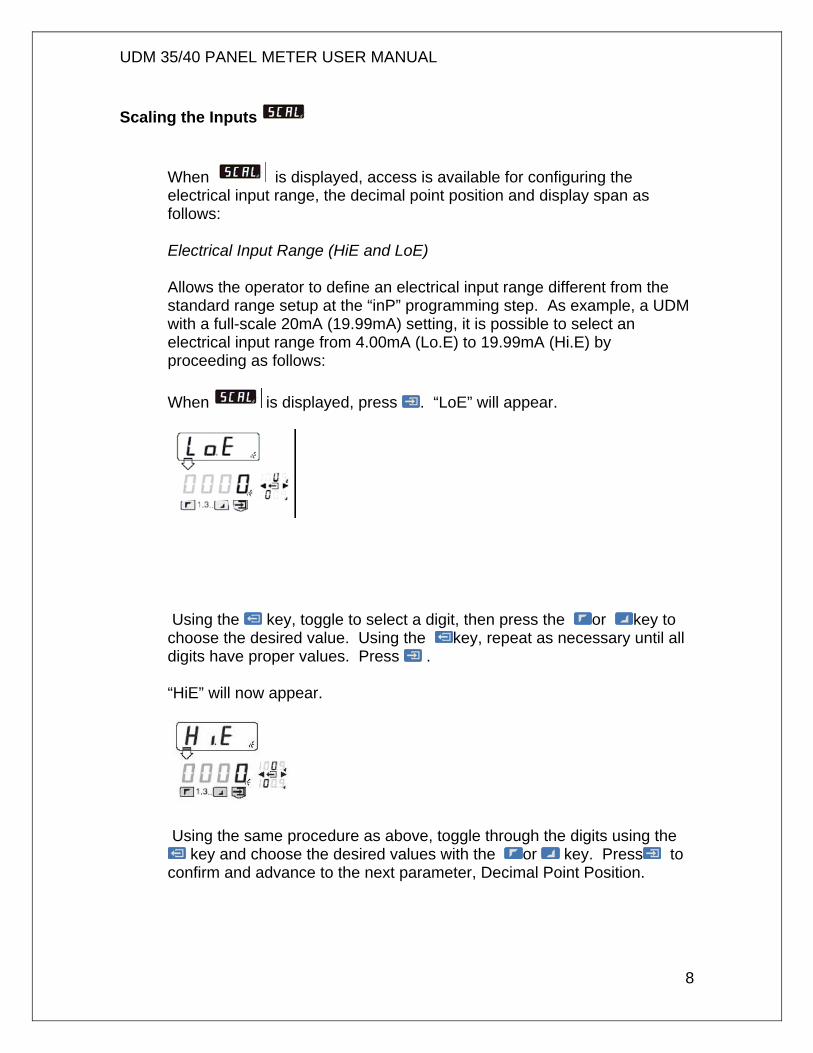
Electrical Input Range (HiE and LoE) Allows the operator to define an electrical input range different from the standard range setup at the “inP” programming step. As example, a UDM with a full-scale 20mA (19.99mA) setting, it is possible to select an electrical input range from 4.00mA (Lo.E) to 19.99mA (Hi.E) by proceeding as follows: When is displayed, press . “LoE” will appear.
Using the key, toggle to select a digit, then press the or key to choose the desired value. Using the key, repeat as necessary until all digits have proper values. Press . “HiE” will now appear.
Using the same procedure as above, toggle through the digits using the
key and choose the desired values with the or key. Press to confirm and advance to the next parameter, Decimal Point Position.
UDM 35/40 PANEL METER USER MANUAL
9
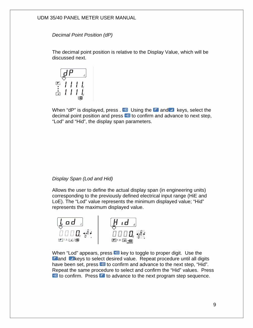
Decimal Point Position (dP) The decimal point position is relative to the Display Value, which will be discussed next.
When “dP” is displayed, press . Using the and keys, select the decimal point position and press to confirm and advance to next step, “Lod” and “Hid”, the display span parameters. Display Span (Lod and Hid) Allows the user to define the actual display span (in engineering units) corresponding to the previously defined electrical input range (HiE and LoE). The “Lod” value represents the minimum displayed value; “Hid” represents the maximum displayed value.
When “Lod” appears, press key to toggle to proper digit. Use the
and keys to select desired value. Repeat procedure until all digits have been set, press to confirm and advance to the next step, “Hid”. Repeat the same procedure to select and confirm the “Hid” values. Press
to confirm. Press to advance to the next program step sequence.
UDM 35/40 PANEL METER USER MANUAL
10
Linearization Introduction
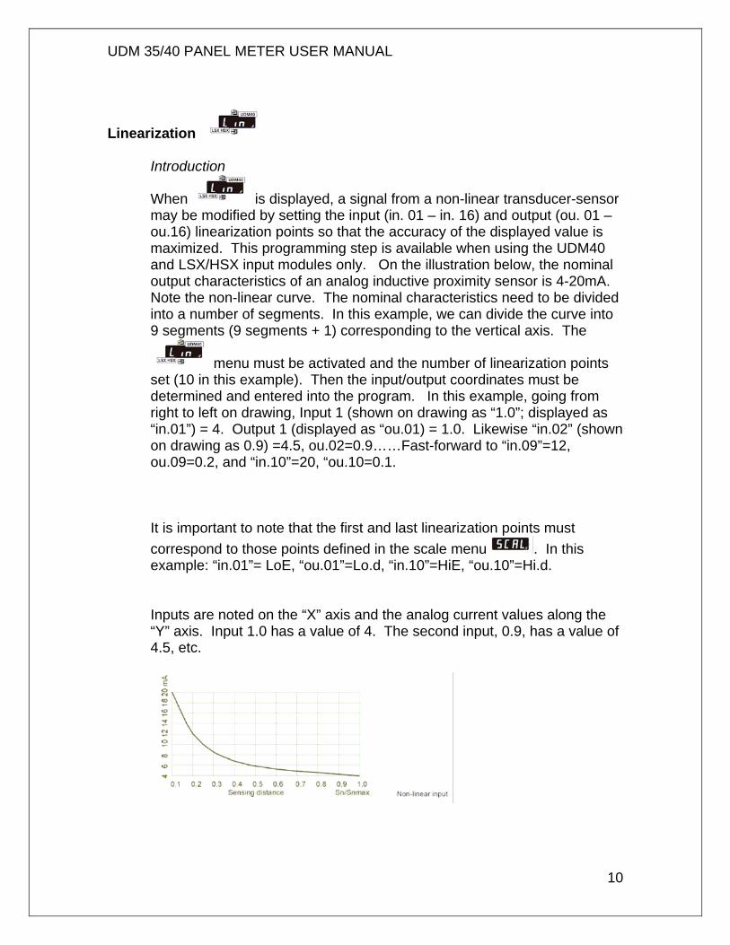
When is displayed, a signal from a non-linear transducer-sensor may be modified by setting the input (in. 01 – in. 16) and output (ou. 01 – ou.16) linearization points so that the accuracy of the displayed value is maximized. This programming step is available when using the UDM40 and LSX/HSX input modules only. On the illustration below, the nominal output characteristics of an analog inductive proximity sensor is 4-20mA. Note the non-linear curve. The nominal characteristics need to be divided into a number of segments. In this example, we can divide the curve into 9 segments (9 segments + 1) corresponding to the vertical axis. The
menu must be activated and the number of linearization points set (10 in this example). Then the input/output coordinates must be determined and entered into the program. In this example, going from right to left on drawing, Input 1 (shown on drawing as “1.0”; displayed as “in.01”) = 4. Output 1 (displayed as “ou.01) = 1.0. Likewise “in.02” (shown on drawing as 0.9) =4.5, ou.02=0.9……Fast-forward to “in.09”=12, ou.09=0.2, and “in.10”=20, “ou.10=0.1. It is important to note that the first and last linearization points must correspond to those points defined in the scale menu . In this example: “in.01”= LoE, “ou.01”=Lo.d, “in.10”=HiE, “ou.10”=Hi.d. Inputs are noted on the “X” axis and the analog current values along the “Y” axis. Input 1.0 has a value of 4. The second input, 0.9, has a value of 4.5, etc.
UDM 35/40 PANEL METER USER MANUAL
11
Navigating & Programming within the Linearization Menu
As appears, press followed by and keys to choose to
ignore or enable linearization . Press to confirm your choice and advance to next step. If you chose YES, you will be prompted to
enter the number of Linearization Points, using the escape button to select the position, and the up /down buttons to select the numerical value, from 01-16. Press enter to confirm and advance. Next, the correlation between the inputs and outputs must be defined in the program. “In.01” will be displayed. Press to toggle through the positions, and use the and keys to select the value. Press to confirm and advance. “Ou.01” will display next. Again, using the escape key , toggle to the appropriate position. Use the and keys to select the value. Press enter to confirm and advance. Repeat this procedure for each set of Inputs and Outputs, up through a maximum of 16. Press the enter key to confirm. Press to advance to the next program step sequence.
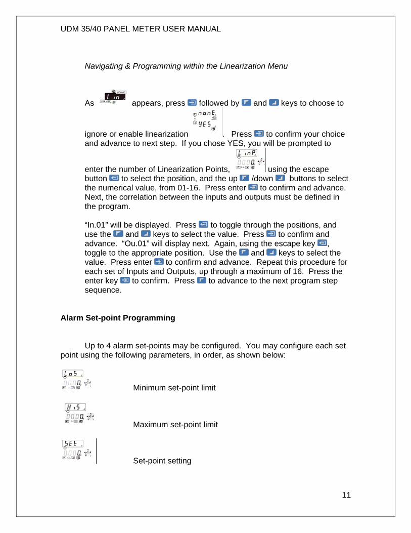
Alarm Set-point Programming Up to 4 alarm set-points may be configured. You may configure each set point using the following parameters, in order, as shown below:
Minimum set-point limit
Maximum set-point limit
Set-point setting
UDM 35/40 PANEL METER USER MANUAL
12
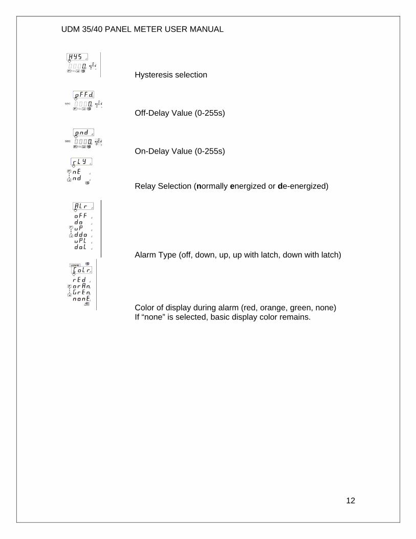
Hysteresis selection
Off-Delay Value (0-255s)
On-Delay Value (0-255s)
Relay Selection (normally energized or de-energized)
Alarm Type (off, down, up, up with latch, down with latch)
Color of display during alarm (red, orange, green, none) If “none” is selected, basic display color remains.
UDM 35/40 PANEL METER USER MANUAL
13
Navigating through this program sequence
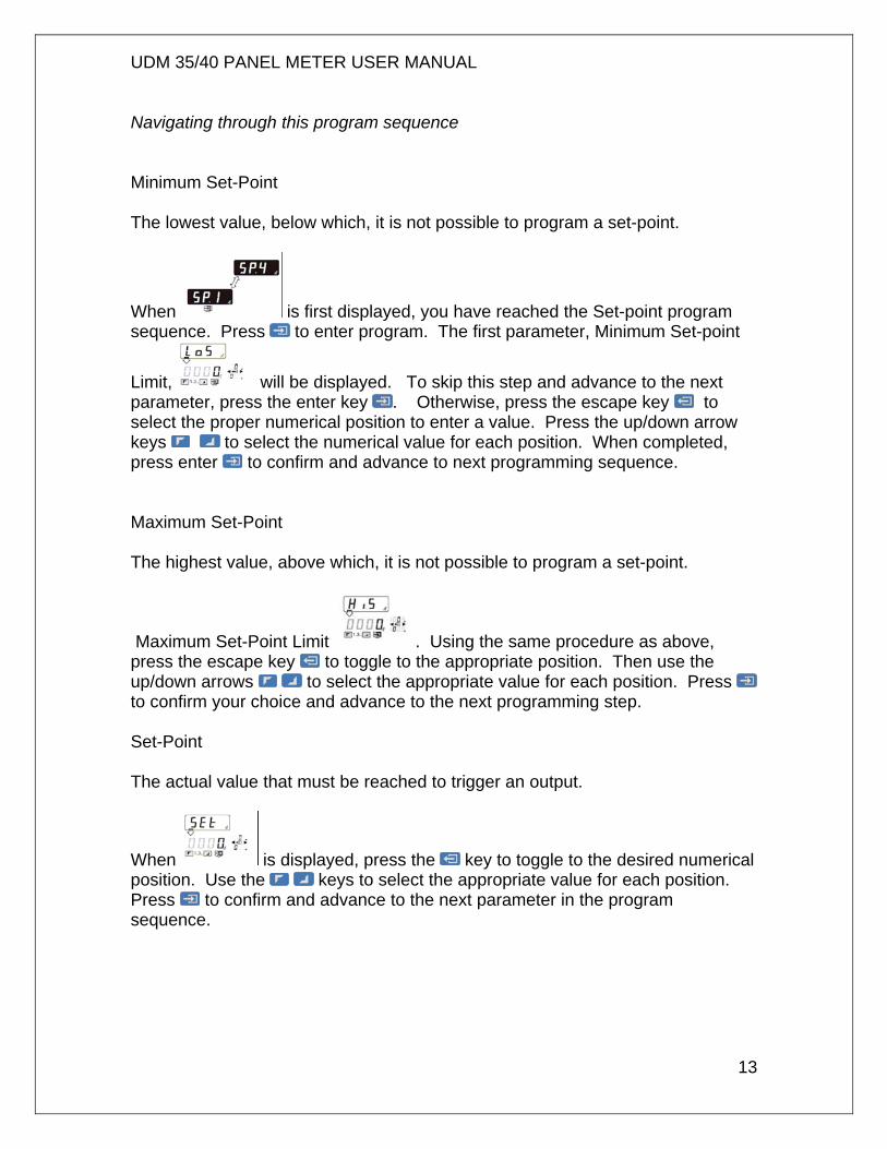
Minimum Set-Point The lowest value, below which, it is not possible to program a set-point.
When is first displayed, you have reached the Set-point program sequence. Press to enter program. The first parameter, Minimum Set-point
Limit, will be displayed. To skip this step and advance to the next parameter, press the enter key . Otherwise, press the escape key to select the proper numerical position to enter a value. Press the up/down arrow keys to select the numerical value for each position. When completed, press enter to confirm and advance to next programming sequence. Maximum Set-Point The highest value, above which, it is not possible to program a set-point.
Maximum Set-Point Limit . Using the same procedure as above, press the escape key to toggle to the appropriate position. Then use the up/down arrows to select the appropriate value for each position. Press to confirm your choice and advance to the next programming step. Set-Point The actual value that must be reached to trigger an output.
When is displayed, press the key to toggle to the desired numerical position. Use the keys to select the appropriate value for each position. Press to confirm and advance to the next parameter in the program sequence.
UDM 35/40 PANEL METER USER MANUAL
14
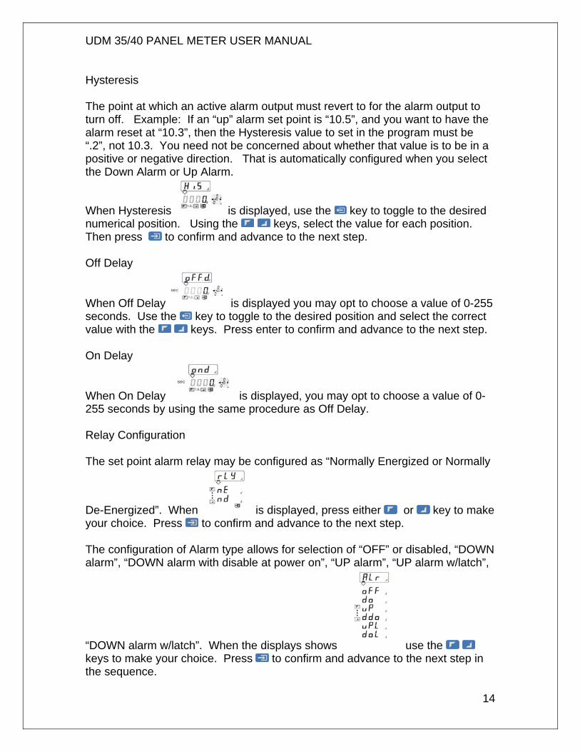
Hysteresis The point at which an active alarm output must revert to for the alarm output to turn off. Example: If an “up” alarm set point is “10.5”, and you want to have the alarm reset at “10.3”, then the Hysteresis value to set in the program must be “.2”, not 10.3. You need not be concerned about whether that value is to be in a positive or negative direction. That is automatically configured when you select the Down Alarm or Up Alarm.
When Hysteresis is displayed, use the key to toggle to the desired numerical position. Using the keys, select the value for each position. Then press to confirm and advance to the next step. Off Delay
When Off Delay is displayed you may opt to choose a value of 0-255 seconds. Use the key to toggle to the desired position and select the correct value with the keys. Press enter to confirm and advance to the next step. On Delay
When On Delay is displayed, you may opt to choose a value of 0-255 seconds by using the same procedure as Off Delay. Relay Configuration The set point alarm relay may be configured as “Normally Energized or Normally
De-Energized”. When is displayed, press either or key to make your choice. Press to confirm and advance to the next step. The configuration of Alarm type allows for selection of “OFF” or disabled, “DOWN alarm”, “DOWN alarm with disable at power on”, “UP alarm”, “UP alarm w/latch”,
“DOWN alarm w/latch”. When the displays shows use the keys to make your choice. Press to confirm and advance to the next step in the sequence.
UDM 35/40 PANEL METER USER MANUAL
15
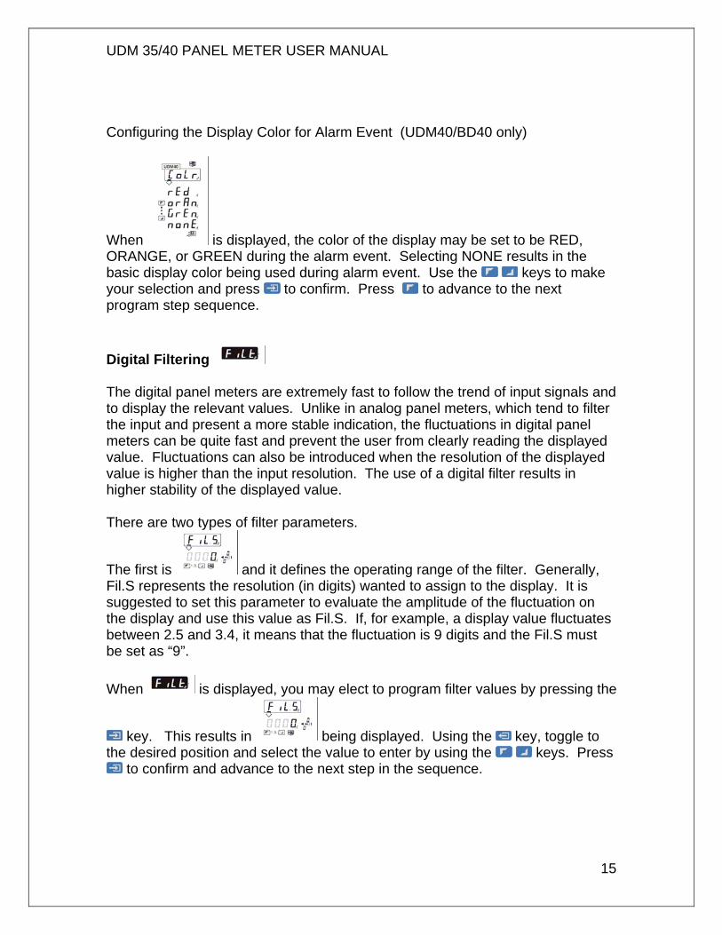
Configuring the Display Color for Alarm Event (UDM40/BD40 only)
When is displayed, the color of the display may be set to be RED, ORANGE, or GREEN during the alarm event. Selecting NONE results in the basic display color being used during alarm event. Use the keys to make your selection and press to confirm. Press to advance to the next program step sequence. Digital Filtering The digital panel meters are extremely fast to follow the trend of input signals and to display the relevant values. Unlike in analog panel meters, which tend to filter the input and present a more stable indication, the fluctuations in digital panel meters can be quite fast and prevent the user from clearly reading the displayed value. Fluctuations can also be introduced when the resolution of the displayed value is higher than the input resolution. The use of a digital filter results in higher stability of the displayed value. There are two types of filter parameters.
The first is and it defines the operating range of the filter. Generally, Fil.S represents the resolution (in digits) wanted to assign to the display. It is suggested to set this parameter to evaluate the amplitude of the fluctuation on the display and use this value as Fil.S. If, for example, a display value fluctuates between 2.5 and 3.4, it means that the fluctuation is 9 digits and the Fil.S must be set as “9”. When is displayed, you may elect to program filter values by pressing the
key. This results in being displayed. Using the key, toggle to the desired position and select the value to enter by using the keys. Press
to confirm and advance to the next step in the sequence.
UDM 35/40 PANEL METER USER MANUAL
16
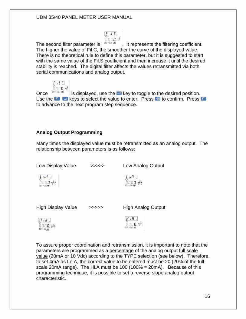
The second filter parameter is . It represents the filtering coefficient. The higher the value of Fil.C, the smoother the curve of the displayed value. There is no theoretical rule to define this parameter, but it is suggested to start with the same value of the Fil.S coefficient and then increase it until the desired stability is reached. The digital filter affects the values retransmitted via both serial communications and analog output.
Once is displayed, use the key to toggle to the desired position. Use the keys to select the value to enter. Press to confirm. Press to advance to the next program step sequence. Analog Output Programming Many times the displayed value must be retransmitted as an analog output. The relationship between parameters is as follows: Low Display Value >>>>> Low Analog Output
High Display Value >>>>> High Analog Output
To assure proper coordination and retransmission, it is important to note that the parameters are programmed as a percentage of the analog output full scale value (20mA or 10 Vdc) according to the TYPE selection (see below). Therefore, to set 4mA as Lo.A, the correct value to be entered must be 20 (20% of the full scale 20mA range). The Hi.A must be 100 (100% = 20mA). Because of this programming technique, it is possible to set a reverse slope analog output characteristic.
UDM 35/40 PANEL METER USER MANUAL
17
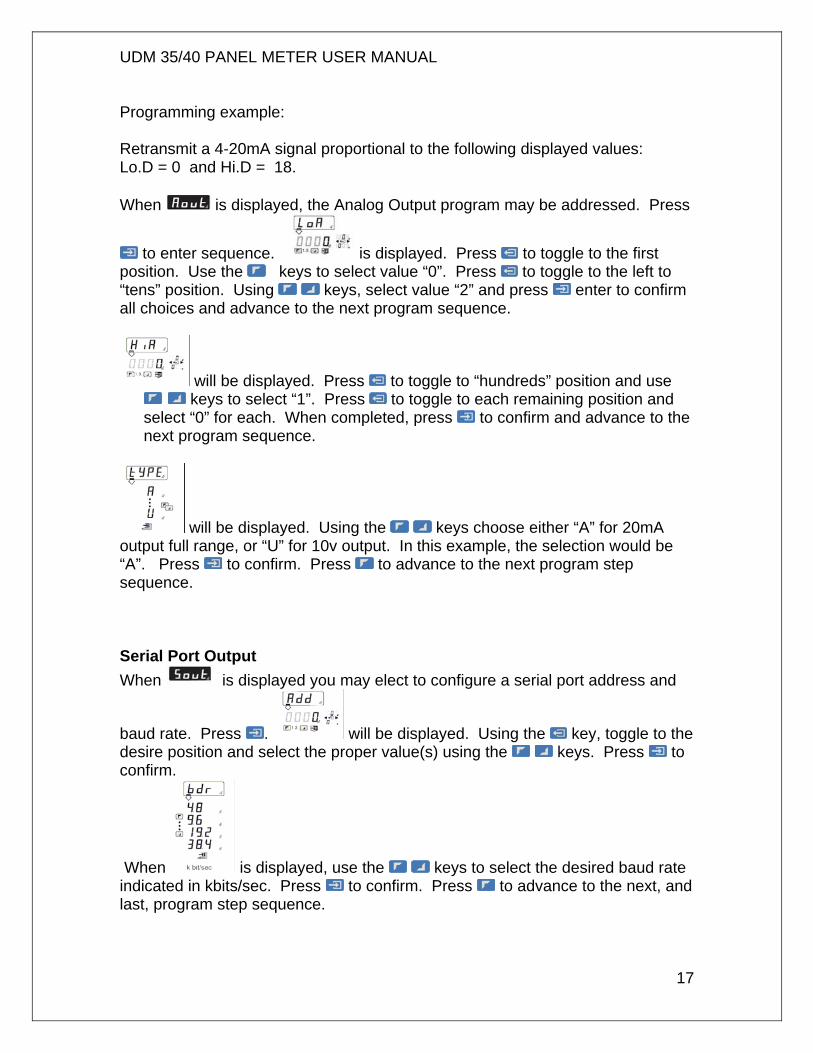
Programming example: Retransmit a 4-20mA signal proportional to the following displayed values: Lo.D = 0 and Hi.D = 18. When is displayed, the Analog Output program may be addressed. Press
to enter sequence. is displayed. Press to toggle to the first position. Use the keys to select value “0”. Press to toggle to the left to “tens” position. Using keys, select value “2” and press enter to confirm all choices and advance to the next program sequence.
will be displayed. Press to toggle to “hundreds” position and use keys to select “1”. Press to toggle to each remaining position and
select “0” for each. When completed, press to confirm and advance to the next program sequence.
will be displayed. Using the keys choose either “A” for 20mA output full range, or “U” for 10v output. In this example, the selection would be “A”. Press to confirm. Press to advance to the next program step sequence. Serial Port Output When is displayed you may elect to configure a serial port address and
baud rate. Press . will be displayed. Using the key, toggle to the desire position and select the proper value(s) using the keys. Press to confirm.
When is displayed, use the keys to select the desired baud rate indicated in kbits/sec. Press to confirm. Press to advance to the next, and last, program step sequence.
CONVERTING CELSIUS TO FAHRENHEIT The UDM35/40 digital panel meters use the Celsius temperature scale. However, the displayed value can easily be scaled to indicate Fahrenheit values by using the following guidelines: The LoE and HiE are always expressed as Celsius values. To display Fahrenheit values, manually convert the LoD to a Fahrenheit value and then convert the HiD to a Fahrenheit value. Ex: LoE is 0 HiE is 100 Manual conversion to Fahrenheit: LoD would be 32 (F) HiD would be 212 (F)
UDM 35/40 PANEL METER USER MANUAL
18
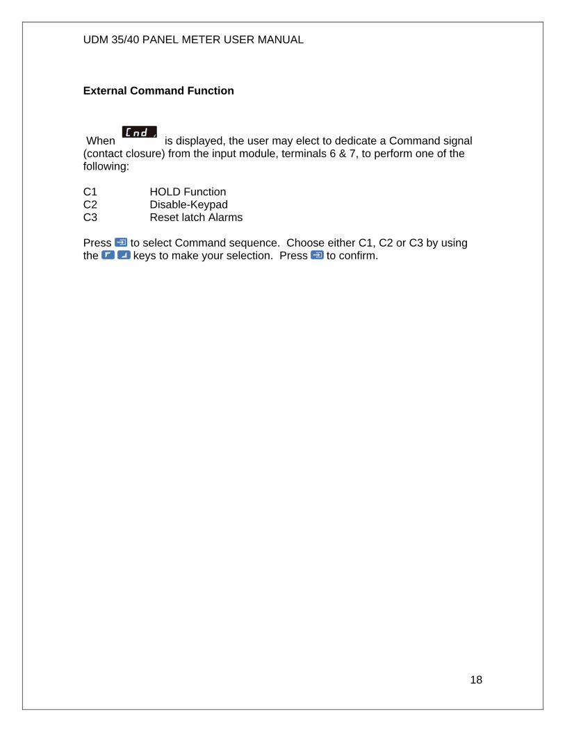
External Command Function
When is displayed, the user may elect to dedicate a Command signal (contact closure) from the input module, terminals 6 & 7, to perform one of the following: C1 HOLD Function C2 Disable-Keypad C3 Reset latch Alarms Press to select Command sequence. Choose either C1, C2 or C3 by using the keys to make your selection. Press to confirm.
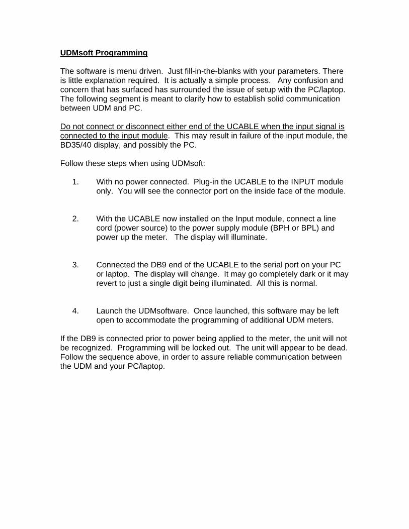
UDMsoft Programming The software is menu driven. Just fill-in-the-blanks with your parameters. There is little explanation required. It is actually a simple process. Any confusion and concern that has surfaced has surrounded the issue of setup with the PC/laptop. The following segment is meant to clarify how to establish solid communication between UDM and PC. Do not connect or disconnect either end of the UCABLE when the input signal is connected to the input module. This may result in failure of the input module, the BD35/40 display, and possibly the PC. Follow these steps when using UDMsoft:
1. With no power connected. Plug-in the UCABLE to the INPUT module only. You will see the connector port on the inside face of the module.
2. With the UCABLE now installed on the Input module, connect a line cord (power source) to the power supply module (BPH or BPL) and power up the meter. The display will illuminate.
3. Connected the DB9 end of the UCABLE to the serial port on your PC or laptop. The display will change. It may go completely dark or it may revert to just a single digit being illuminated. All this is normal.
4. Launch the UDMsoftware. Once launched, this software may be left open to accommodate the programming of additional UDM meters.
If the DB9 is connected prior to power being applied to the meter, the unit will not be recognized. Programming will be locked out. The unit will appear to be dead. Follow the sequence above, in order to assure reliable communication between the UDM and your PC/laptop.
UDM 35/40 PANEL METER USER MANUAL
19
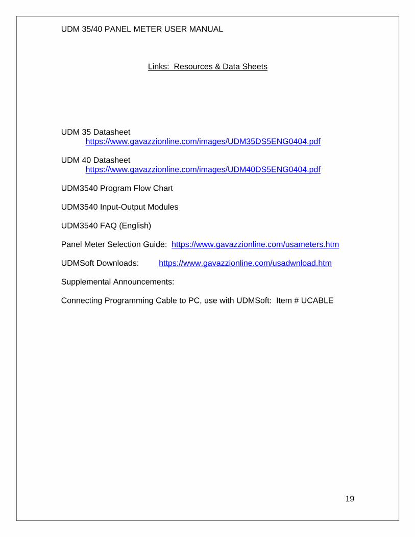
Links: Resources & Data Sheets
UDM 35 Datasheet https://www.gavazzionline.com/images/UDM35DS5ENG0404.pdf UDM 40 Datasheet https://www.gavazzionline.com/images/UDM40DS5ENG0404.pdf UDM3540 Program Flow Chart UDM3540 Input-Output Modules UDM3540 FAQ (English) Panel Meter Selection Guide: https://www.gavazzionline.com/usameters.htm UDMSoft Downloads: https://www.gavazzionline.com/usadwnload.htm Supplemental Announcements: Connecting Programming Cable to PC, use with UDMSoft: Item # UCABLE