Carillon Tower Design and Construction - The Guild of Carillonneurs
46
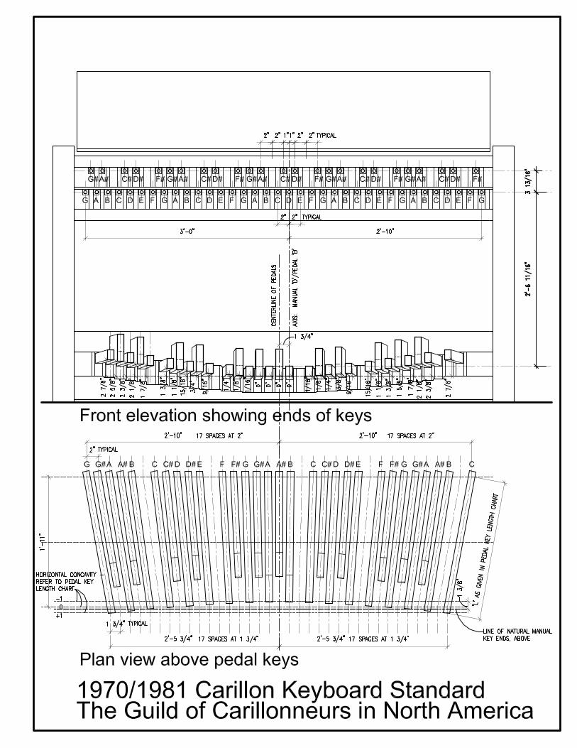
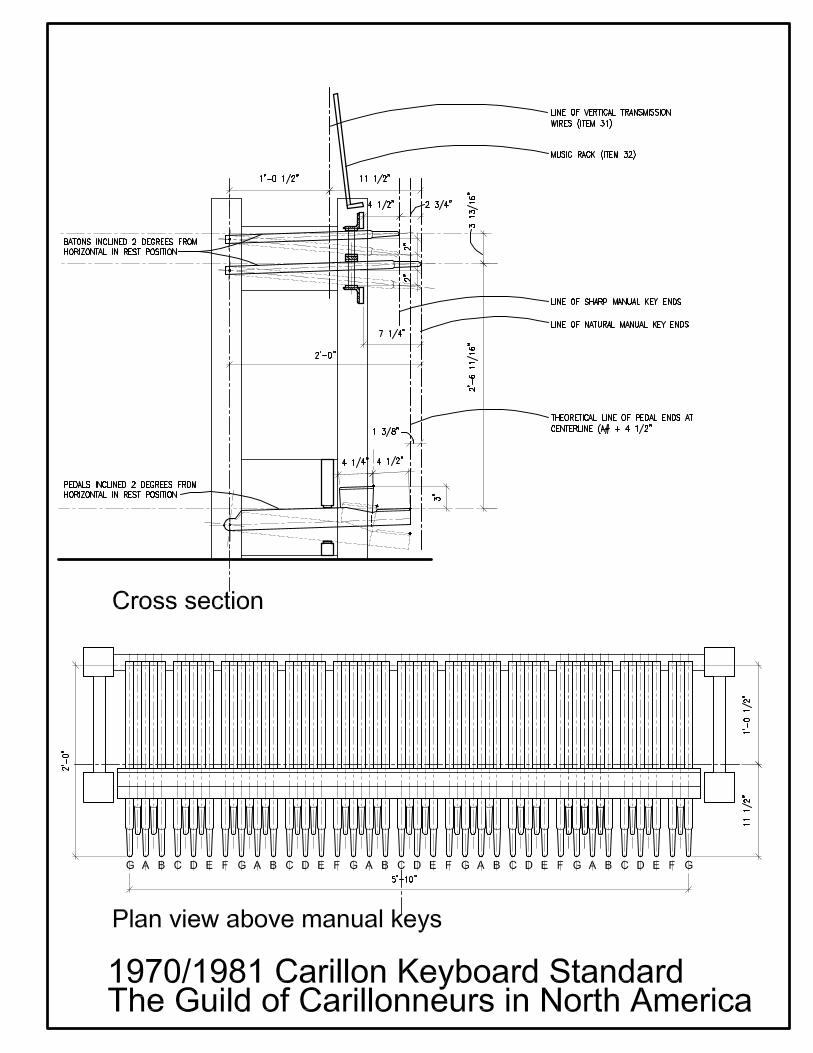
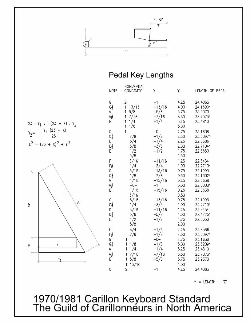
Carillon Tower Design and Construction Table of Contents Introduction 1 Rules and Regulations A Zoning Ordinances B Building Codes C OSHA Regulations 2 Design of Carillon Towers A The Client and the Program B The Site C Structure D Access E The Bellchamber F The Playing Cabin G Adapting Existing Towers 3 Appendices A List of Bellfounders and Carillon Builders B List of Carillon Consultants C Illustrations D GCNA Keyboard Standards Introduction The purpose of this paper is to outline some of the considerations and factors associated with the design of towers for manually played, cast bronze bell carillons. It is intended to provide basic code information and design concepts to both professionals (architects, engineers) and laypersons who may be involved in the design, construction or renovation of carillon towers. For a general description and discussion of the carillon, please refer to the GCNA publication “The Carillon.” The writer would like to thank Richard Watson and Anthony Gholz, AIA, for their contributions to this paper. Rick Watson shared a number of thoughtful and well reasoned ideas on carillon, bellchamber and playing cabin design, and Anthony Gholz shared his experience researching the building code in preparation for the design of the new tower for St. Hugo of the Hills Church in Bloomfield Hills, Michigan. Thanks are also extended to Sue Wood for her expert proofreading and helpful comments. While every attempt has been made to present ideas and concepts as objectively as possible, any discussion involving design will by nature be subjective, at least in part, and the writer’s own bias, experiences and interpretations are surely reflected in the text that follows, however unintentional. All comments, criticism and corrections would be greatly appreciated and may be forwarded via e-mail or regular mail. May 2, 2005 Revised, May 2006 Patrick Macoska Registered Architect, State of Michigan Chairperson, GCNA Tower Construction and Renovation Committee Carillon Tower Design and Construction 1
Transcript of Carillon Tower Design and Construction - The Guild of Carillonneurs
Carillon Tower Design and Construction Table of Contents Introduction 1 Rules and Regulations A Zoning Ordinances B Building Codes C OSHA Regulations 2 Design of Carillon Towers A The Client and the Program B The Site C Structure D Access E The Bellchamber F The Playing Cabin G Adapting Existing Towers 3 Appendices A List of Bellfounders and Carillon Builders B List of Carillon Consultants C Illustrations D GCNA Keyboard Standards Introduction The purpose of this paper is to outline some of the considerations and factors associated with the design of towers for manually played, cast bronze bell carillons. It is intended to provide basic code information and design concepts to both professionals (architects, engineers) and laypersons who may be involved in the design, construction or renovation of carillon towers. For a general description and discussion of the carillon, please refer to the GCNA publication “The Carillon.” The writer would like to thank Richard Watson and Anthony Gholz, AIA, for their contributions to this paper. Rick Watson shared a number of thoughtful and well reasoned ideas on carillon, bellchamber and playing cabin design, and Anthony Gholz shared his experience researching the building code in preparation for the design of the new tower for St. Hugo of the Hills Church in Bloomfield Hills, Michigan. Thanks are also extended to Sue Wood for her expert proofreading and helpful comments. While every attempt has been made to present ideas and concepts as objectively as possible, any discussion involving design will by nature be subjective, at least in part, and the writer’s own bias, experiences and interpretations are surely reflected in the text that follows, however unintentional. All comments, criticism and corrections would be greatly appreciated and may be forwarded via e-mail or regular mail. May 2, 2005 Revised, May 2006 Patrick Macoska Registered Architect, State of Michigan Chairperson, GCNA Tower Construction and Renovation Committee
Carillon Tower Design and Construction 1
1 Rules and Regulations This discussion will focus on rules and regulations that govern the design and construction of towers housing manually played carillons, specifically:
• Zoning Ordinances • Building Codes • OSHA Regulations
A Zoning Ordinances Zoning Ordinances are rules and regulations adopted by a local governmental entity, usually a city, town, village or township. In rural or sparsely populated areas, zoning is often regulated at the county level. The objective of Zoning Ordinances is to create an environment that enhances the public health, safety and welfare through regulation of land use and type and size of structures built on the land. Ordinances typically specify area, height and bulk of building allowed; setbacks from property lines; parking required; landscaping; screening; and other requirements based on the type of land use. Land uses are organized in categories (i.e., residential, commercial, institutional, industrial, recreational, agricultural, etc.) and are usually depicted graphically in the form of a Land Use or Zoning Map. The geographic organization of land uses depicted in a Zoning Map often follows from a Master Land Use Plan adopted by the local government. Zoning Ordinances are laws, formally adopted by the governmental entity (city council, township board, county commissioners, etc.). The Ordinances in printed form and the Zoning Map are usually available to the public at the governmental offices (city hall, county offices, etc.). Enforcement of Zoning Ordinances takes place at several levels. For new projects, a formal submittal must be made to the Planning Commission that normally meets on a monthly basis. This Commission, composed of members of the community either appointed or elected, will evaluate whether a proposed project meets all the particular requirements of the ordinances that apply. If deficiencies are found, it may table the item and request the petitioner to amend the proposal and resubmit it. If the proposal is found to be in substantial compliance, the commission may recommend approval with or without qualifications. Actual approval of a proposal, allowing a petitioner to move ahead to develop their land, is given by the governing body (i.e., city council, township board of trustees, etc.). Usually, but not always, this body will vote based on the recommendation of the Planning Commission. The Site Plan Approval process just described usually is required for larger projects; smaller scale endeavors like single family residences are normally checked by the Zoning Administrator for compliance and approved by the Building Department. If a proposed project requires a change to the zoning for a parcel of land, or an exception to a specific zoning requirement (such as a setback or height requirement), application must be made to the Zoning Board of Appeals. This group is part of the local government and normally consists of appointees who meet monthly. With regard to bell towers, because their height is likely to exceed the allowable under the ordinance, it may be necessary to seek an exception via the appeals process. It should be noted that all meeting related to zoning issues (Planning Commission, Zoning Board of Appeals, City Council meetings, etc.) are open to the public and usually offer an opportunity for the public to be heard. By law, public notice must be given of meetings and agendas. A note of caution to those planning a carillon tower: while the notion of a bell tower might seem innocent enough, there are instances of projects being tied up for years in the approval process, sometimes resulting in litigation against the local government (example: Ward Presbyterian Church, Northville Township, Michigan, over height restrictions). Because meetings are open to the public, local residents can be quite vocal in voicing opposition to a proposed project if they feel it is out of character to the area (whether or not it meets zoning requirements). A final note on ordinances: in addition to zoning ordinances, many communities have enacted general ordinances that govern acceptable behavior, etc., within the community. Such ordinances often include regulations governing noise. Exception is often made for church bells. It is worthwhile checking your
Carillon Tower Design and Construction 2
local ordinance to determine how it might apply to carillon music. Occasionally these ordinances are tested and generate some controversy (example: an Islamic mosque in Hamtramck, Michigan, wishing to broadcast prayers over loudspeakers. Public hearings were held, both opposition and support were voiced, precedent of church bells was cited, ordinance was amended by city council to allow broadcast of prayers). B Building Codes While zoning ordinances deal in a general manner with the area, height and bulk of a building, building codes define in great detail the requirements of building construction. In the past, building codes varied considerably and were adopted in a somewhat haphazard fashion, sometimes at the local level, sometimes at the state level. In recent years, an effort has been made by the International Code Council to create a comprehensive model building code by merging the several model codes in the U. S.: BOCA (Building Officials and Code Administrators International, Inc.), ICBO (International Conference of Building Officials), and SBCCI (Southern Building Code Congress International, Inc). The result of this effort was the 2000 International Building Code. At present this code has been adopted (at least in part) in 44 states and the District of Columbia. In many of these states, the code has been voted into law by the legislature and is enforced as the official building code of the state. The International Building Code is part of a family of codes that include the International Plumbing Code, the International Mechanical Code, the International Electrical Code, and the International Fire Code, among others. These codes are maintained, updated and revised on a 3-year cycle. While many states enforce this code statewide, in some areas it is enforced locally. To check whether your area is governed by a version of the International Building Code, you may visit their website at www.ibcsafe.org. Because the International Building Code is now so prevalent and serves as the basis for many of the building codes now used around the country, the 2006 IBC will be used as the basis for the following discussion of building codes as they pertain to carillon towers. The Building Code is organized in 34 chapters and 11 Appendices. The chapters highlighted in bold type are particularly relevant to carillon towers. Chapter 1 Administration Chapter 2 Definitions Chapter 3 Use and Occupancy Classifications Chapter 4 Special Detailed Requirements Based on Use and Occupancy Chapter 5 General Building Heights and Areas Chapter 6 Types of Construction Chapter 7 Fire-Resistance Rated Construction Chapter 8 Interior Finishes Chapter 9 Fire Protection Systems Chapter 10 Means of Egress Chapter 11 Accessibility Chapter 12 Interior Environment Chapter 13 Energy Efficiency Chapter 14 Exterior Walls Chapter 15 Roof Assemblies and Rooftop Structures Chapter 16 Structural Design Chapter 17 Structural Tests and Special Inspections Chapter 18 Soil and Foundations Chapter 19 Concrete Chapter 20 Aluminum Chapter 21 Masonry Chapter 22 Steel Chapter 23 Wood Chapter 24 Glass and Glazing
Carillon Tower Design and Construction 3
Chapter 25 Gypsum Board and Plaster Chapter 26 Plastic Chapter 27 Electrical Chapter 28 Mechanical Systems Chapter 29 Plumbing Systems Chapter 30 Elevators and Conveying Systems Chapter 31 Special Constructions Chapter 32 Encroachments into the Public Right-of-Way Chapter 33 Safeguards During Construction Chapter 34 Existing Structures Chapter 35 Referenced Standards Appendix A Employee Qualifications Appendix B Board of Appeals Appendix C Group U- Agricultural Buildings Appendix D Fire Districts Appendix E Supplementary Accessibility Requirements Appendix F Rodent Proofing Appendix G Flood Resistant Construction Appendix H Signs Appendix I Patio Covers Appendix J Grading Appendix K ICC Electrical Code The following narrative is only a summary of certain parts of the building code. Sections that are quoted in full are enclosed in quotation marks. Editorial comments are enclosed in brackets. Chapter 3 Use and Occupancy Classifications The Building Code establishes classifications for all buildings and structures as follows: Assembly (A) Business (B) Educational (E) Factory and Industrial (F) High Hazard (H) Institutional (I) Mercantile (M) Residential (R) Storage (S) Utility and Miscellaneous (U) The only classification in which towers are specifically mentioned is Use Group U, Utility and Miscellaneous. “Section 312.1 General. Buildings and structures of an accessory character and miscellaneous structures not classified in any specific occupancy shall be constructed, equipped and maintained to conform to the requirements of this code commensurate with the fire and life hazard incidental to their occupancy. Group U shall include, but not be limited to, the following:…Towers”
Carillon Tower Design and Construction 4
[A case can generally be made for a freestanding carillon tower falling into Use Group U. When a tower is part of another use, as in a church (Use Group A-3) or academic building (Use Group E), it can be more complicated. Section 302.3, mixed occupancies, addresses this issue. The combination of a carillon tower with another use can be viewed as nonseparated uses, in which the most restrictive provisions of the code must apply to the entire structure. This can have significant impact on the tower with regard to egress, accessibility and other concerns. Another option offered in the code is separated uses, in which different uses exist in the same structure but are separated by fire walls or other fire rated construction such that the individual uses can be considered separate buildings in terms of life safety. This may permit application of less restrictive code requirements to the tower component.] Chapter 5 General Building Heights and Areas The building code sets limits to area and height of buildings based on their Use Group and Construction Type (see Chapter 6). Generally, the more fire resistant the construction type, the taller a structure can be. Section 504.3 has particular relevance: “504.3 Roof Structures. Towers, spires, steeples and other roof structures shall be constructed of materials consistent with the required type of construction of the building except where other construction is permitted by Section 1509.2.1. Such structures shall be unlimited in height if of noncombustible materials and shall not extend more than 20 feet above the allowable height if of combustible materials. See Chapter 15 for additional requirements.” Chapter 6 Types of Construction Construction Types range from Type I through Type V, with Type I considered the most fire resistant (and therefore safest) and allowing in most cases building of unlimited area and height, unless restricted elsewhere in the code or by zoning regulations. Generally, Types I and II Construction are of noncombustible material, Types III and IV Construction contain both combustible and noncombustible elements, and Type V Construction generally applies to wood frame (combustible) construction. Towers that are steel framed would generally fall into either Type I or II Construction, while towers with load bearing masonry walls would be classified as Type III or IV Construction, depending on the details of the floor and roof framing. Chapter 7 Fire-Resistance Rated Construction Several sections of this chapter are relevant to carillon towers.
• Sections 704.8 Allowable area of openings. The percentage of exterior wall opening permitted is a function of the distance of the structure from adjacent buildings or property lines. Each face of the building must be evaluated according to this criterion. Table 704.8 gives percentages of opening allowable for specific distances. In general, if a structure is more than 30 feet from another building or property line, the amount of wall opening is unlimited. [It is unlikely that the wall opening required at the bellchamber for good egress of sound as a percentage of total wall area would be below the allowable based on separation, but it should be checked].
• Section 704.10 Vertical exposure. In cases where a tower is part of another building and extends above a lower roof, this section specifies that there can be no opening less than 15 feet above the roof below unless that roof has a fire-resistance rating of one hour.
• Section 707.2 Shaft enclosure required. Exception 7 of this provision allows a stair to not be enclosed in fire rated construction if 6 conditions are met, the most relevant being that the stair does not connect more than two stories. [A tower in which the playing cabin is the only occupiable level above the ground level would be considered a two story building, and this exception would apply. If there are other intervening, occupiable floors in the tower, the stair would have to be enclosed with fire rated wall construction].
Chapter 7 also defines in detail other types of fire rated construction, such as fire walls and floor assemblies that might be used to separate a tower in a mixed use building, as described in Chapter 3 above.
Carillon Tower Design and Construction 5
Chapter 8 Interior Finishes If the tower can be classified as Use Group U, there are no restrictions to the type of interior finishes. If the tower is part of another building and falls under the Use Group designation of the main building, certain restrictions may apply to wall, ceiling and floor finishes within the tower. Table 803.5 illustrates the class designation for interior finishes (A, B or C) as a function of location and Use Group. The classifications are defined as:
• Class A: flame spread 0-25; smoke developed 0-450 (least flammable) • Class B: flame spread 26-75; smoke developed 0-450 • Class C: flame spread 76-200; smoke developed 0-450.
Generally, Class A finishes are required where life safety is most critical: in exitways, in unsprinklered buildings, and certain Institutional uses. Section 804 Interior Floor Finish: exception to compliance is made for certain material: “804.1 General: Interior floor finish and floor covering materials shall comply with Section 804.2 through 804.4.1.
Exception: Floor finishes and coverings of a traditional type, such as wood, vinyl, linoleum or terrazzo, and resilient floor covering materials which are not comprised of fibers.”
Chapter 9 Fire Protection Systems Section 903.2.10.3 Buildings 55 feet or more in height. “An automatic sprinkler system shall be installed throughout buildings with a floor level having an occupant load of 30 or more that is located 55 feet or more above the lowest level of fire department vehicle access.” [As long as the occupant load is less than 30, which is likely for a basic carillon tower with a playing cabin and no intervening floors, sprinklers are not required in the tower.] Section 905 Standpipe Systems: A standpipe is a water supply system to which firefighters can connect a fire hose. Standpipes are required where the floor level of the highest story is more than 30 feet above “the lowest level of the fire department vehicle access” (that is, ground level). The 30 foot dimension is a result of the length of hose stream from a fire hose. The provision of a standpipe system allows firefighters to connect a hose at each floor in order to reach all points in taller buildings. [The playing cabins in most carillon towers are more than 30 feet above the ground level, and therefore a standpipe would be required if this section is strictly interpreted. (There are no exceptions for Use Group U). The intent of this section seems to be to permit adequate firefighting capability in larger buildings with high populations. The floor area in a typical tower, especially one where the only story above ground level is the playing cabin, is quite small and the occupancy load is also quite small, usually just the carillonneur. On this basis, a case can be made that a standpipe system will not contribute significantly to the safety of the building and therefore should not be required. This point has been successfully argued on recent tower projects; it is worth discussing this item with the local building official and/or fire marshal]. Chapter 10 Means of Egress This chapter describes in detail the number, size and construction of required exits based on the Use Group and size of the building. Exit is a broad term that refers to all the components in the path of egress, including corridors, stairs and exit doors. In order to establish what the exiting requirements for a tower are, the occupant load must first be determined. Table 1004.1.1 gives maximum floor area allowances per occupant for various Use Groups. This table does not have a category for Use Group U and is therefore not much help in determining occupant load. Section 1004.1.1, however, allows the occupant load to be determined by the actual number of people who will likely occupy the space. [In the case of a carillon tower, this is usually one
Carillon Tower Design and Construction 6
person, but occasionally may be more if teaching takes place in the tower or if the tower is open to visitors from time to time]. Section 1011.1 Exit Signs. “Exit signs are not required in rooms or areas which require only one exit or exit access.” Section 1008.1.1 Size of doors. The minimum width for exit doors is 32” clear; that is, measured from jamb to surface of door when the door is in the open position. In practice, exit doors are usually not less than 36” wide. Minimum height is 80”. Section 1009 Stairways. A stair must be provided as the means of egress, as a minimum. An elevator alone is not sufficient, nor are ladders permitted as a means of egress. Some requirements for a conventional stair:
• Minimum width: 36” for an occupant load of less than 50 (which should apply to most towers); 44” for occupant load of 50 and over.
• Minimum headroom: 80” • Maximum stair riser dimension: 7” • Tread depth dimension: 11” • Maximum vertical rise between floors or landings: 12 feet • Guardrails: minimum 42” high on open side of stairs, with maximum openings such that a 4”
sphere cannot pass through any opening up to a height of 34” • Handrails: required on both sides, between 34” and 38” in height measured from the stair tread
nosing Section 1009.8 Spiral Stairways. Spiral stairways are permitted where the occupant load is 5 or less and the space being served does not exceed 250 square feet. This is a viable option for towers where the floor area of the playing cabin often does not exceed 250 square feet, the occupant load is not expected to exceed 5 persons, and space is at a premium. The code gives these requirements for spiral stairways:
• Minimum clear tread depth: 7.5” at a point 12 inches from the narrow edge • Riser height: sufficient to provide headroom of 78” minimum, but riser height shall not be more
than 9.5” • Minimum width: 26” (when factoring a center post dimension of 4” to 6”, a diameter of 5’-0” is
usually required to meet all the provisions for a spiral stairway) Section 1015 states that only one exit is required for Use Group U with a maximum occupant load of 49 (Table 1015.1). Section 1019.2 also allows a single exit from Use Group U (as well as several others) provided the exit serves only one story above the grade plane and the occupant load is 49 or less. Section 1020 Vertical exit enclosures. “In all occupancies, other than Group H and I occupancies, a stairway is not required to be enclosed when the stairway serves an occupant load of less than 10 and the stairway complies with either Item 1.1or 1.2. In all cases, the maximum number of connecting open stories shall not exceed two.
1.1. The stairway is open to not more than one story above the story at the level of exit discharge; or
1.2. The stairway is open to not more than one story below the story at the level of exit discharge.
Chapter 11 Accessibility Section 1103.2.5 Utility Buildings. “Occupancies in Group U are exempt from the requirements of this chapter other than the following:
Carillon Tower Design and Construction 7
1. In agricultural buildings, access is required to paved work areas and areas open to the general public.
2. Private garages or carports that contain required accessible parking.” [If the tower is part of a larger building and is classified other than Use Group U, accessibility by the physically disabled may be required]. [While the building code does not specifically discuss accessibility as applied to carillon towers, at least two principles seem to emerge in this chapter:
1. Accessibility is required in buildings and facilities open to the general public. This would include places of employment and multifamily housing. Exemptions are made for detached dwellings (single family residences), utility buildings (as noted above), construction sites, limited access spaces, equipment spaces and single occupant structures. A case can be made that most carillon towers are not open to the general public and are generally occupied only by the carillonneur. (The practice of holding “open towers” for visitors following recitals weakens this argument somewhat).
2. The code seems to recognize that certain activities require a person to be able-bodied and therefore accessibility is not required to certain spaces. In Section 1103.2.7, Raised areas, the code states “Raised areas used primarily for purposes of security, life safety, or fire safety including, but not limited to, observation galleries, prison guard towers, fire towers, or life guard stands are not required to be accessible or to be served by an accessible route.” It has generally been upheld that certain professions such as public safety, firefighting, corrections, armed services, etc., may establish minimum physical requirements because of tasks that must be performed in the course of duty, and to do so does not discriminate against the physically disabled. It can be argued that a carillonneur must by definition be reasonably able-bodied to perform on the carillon and that carillon towers should therefore not be required to be accessible.
The exemption given to Use Group U buildings probably contains elements of both these points: that towers are generally limited access buildings (not open to the public) and that the type of work taking place in most towers requires the efforts of able-bodied persons.] Chapter 12 Interior Environment This chapter sets minimum requirements for light and ventilation. “1203.4 Natural ventilation. Natural ventilation of an occupied space shall be through windows, doors, louvers or other openings to the outdoors.” “1203.4.1 Ventilation area required. The minimum openable area to the outdoors shall be 4 percent of the floor area being ventilated.” 1204 Temperature Control “1204.1 Equipment and systems. Interior spaces intended for human occupancy shall be provided with space-heating systems capable of maintaining a minimum indoor temperature of 68 degrees F (20 degrees C) at a point 3 feet (914 mm) above the floor on the design heating day. Exception: Interior spaces where the primary purpose is not associated with human comfort.” Section 1205 Lighting “1205.1 General. Every space intended for human occupancy shall be provided with natural light by means of exterior glazed openings in accordance with Section 1205.2 or shall be provided with artificial light in accordance with Section 1205.3…”
Carillon Tower Design and Construction 8
“1205.2 Natural light. The minimum net glazed area shall not be less than 8 percent of the floor area of the room served.” “1205.3 Artificial light. Artificial light shall be provided that is adequate to provide an average illumination of 10 footcandles (107 lux) over the area of the room at a height of 30 inches (762 mm) above the floor level.” Section 1208 Interior Space Dimensions “1208.1 Minimum room widths. Habitable spaces, other than a kitchen, shall not be less then 7 feet (2134 mm) in any plan dimension….” “1208.2 Minimum ceiling heights. Occupiable spaces, habitable spaces and corridors shall have a ceiling height of not less than 7 feet 6 inches (2286 mm)….” Chapter 14 Exterior Walls This chapter describes various exterior wall materials (including wood siding, masonry veneer, stone veneer, terra cotta, metal veneer and others) and the means by which they must be attached to the building structure. Note especially that anchors and ties that hold veneer to the structure and are concealed within the wall after construction is complete are required to be corrosion resistant (i.e., hot- dipped galvanized or stainless steel). The reason is that water from rain and snow will inevitably work its way through the veneer or the joints between veneer units and potentially cause rusting of the anchors and ties if they are not corrosion resistant. Because they are concealed, rusting and corrosion of anchors may begin and progress undetected until signs such as cracking and spalling are apparent, by which time severe damage will have occurred within the walls. Chapter 15 Roof Assemblies and Rooftop Structures “1509.5 Towers, spires, domes and cupolas. Any tower, spire, dome or cupola shall be of a type of construction not less in fire-resistance rating than required for the building to which it is attached, except that any such tower, spire, dome or cupola that exceeds 85 feet (25 908 mm) in height above grade plane, exceeds 200 square feet (18.6 m2) in horizontal area or is used for any purpose other than a belfry or an architectural embellishment shall be constructed of and supported on Type I or II construction.” “1509.5.1 Noncombustible construction required. Any tower, spire, dome or cupola that exceeds 60 feet (18 288) in height above the highest point at which it comes in contact with the roof, or that exceeds 200 square feet (18.6 m²) in area at any horizontal section, or which is intended to be used for any purpose other than a belfry or architectural embellishment, shall be entirely constructed of and supported by noncombustible materials. Such structures shall be separated from the building below by construction having a fire resistance rating of not less than 1.5 hours with openings protected with a minimum 1.5 hour fire-protections rating….” Chapter 34 Existing Structures “3403.1 Existing buildings or structures. Additions or alterations to any building or structure shall comply with the requirements of the code for new construction. Additions and alterations shall not be made to an existing building or structure that will cause the existing building or structure to be in violation of any provisions of this code. An existing building plus additions shall comply with the height and area provisions of Chapter 5. Portions of the structure not altered and not affected by the alteration are not required to comply with the code requirements for a new structure.”
Carillon Tower Design and Construction 9

“3403.4 Stairways. An alteration or the replacement of an existing stairway in an existing structure shall not be required to comply with the requirements of a new stairway as outlined in Section 1009 where the existing space and construction will not allow a reduction in pitch or slope.” “3407.1 Historic Buildings. The provisions of this code relating to the construction, repair, alteration, addition, restoration and movement of structures, and change of occupancy shall not be mandatory for historic buildings where such buildings are judged by the building official to not constitute a distinct life safety hazard.” “Section 3410 Compliance Alternatives. 3410.1 Compliance. The provisions of this section are intended to maintain or increase the current degree of public safety, health and general welfare in existing buildings while permitting repair, alteration, addition and change of occupancy without requiring full compliance with Chapters 2 through 33, or Sections 3401.3, and 3403 through 3407, except where compliance with other provisions of this code is specifically required in this section.” [This provision allows existing buildings to be evaluated on a case-by-case basis by the local building official. It is the Owner’s responsibility to have the existing building professionally investigated and evaluated, and the data obtained presented to the building official.] C OSHA Rules and Regulations OSHA (Occupational Safety and Health Administration) Regulations are quite extensive; the regulations that are most relevant to bell towers are those that pertain to ladders, since ladders are often used to access the bellchamber from the playing cabin. The following is a summary of requirements for fixed ladders taken from MIOSHA (the Michigan version of OSHA).
• Minimum concentrated load: 300 lbs. • Distance between rungs, cleats or steps: 12 inches • Clear length of rungs, cleats or steps: 16 inches, and designed in such a way that a foot cannot
slide off the end. • Diameter of ladder rungs: ¾ inch minimum • Bearing surface of metal cleats: ½” minimum • Side rails: “A side rail which might be used as a climbing aid shall be of such cross section as to
afford a gripping surface without sharp edges, splinters or burrs.” • Clearance: “(1) The perpendicular distance from the center line of the rungs on the climbing side
of a fixed ladder shall not be less than 36 inches for a pitch of 76 degrees, and not less than 30 inches for a pitch of 90 degrees to the nearest permanent object, except with respect to a cage or well installation. The minimum clearance for intermediate pitches between these 2 limits shall be in proportion to the slope. (2) A clear width of not less than 15 inches shall be provided each way from the center line of the fixed ladder to the nearest permanent object, except with respect to a cage or well installation. (3) The perpendicular distance from the center line of the rung on the back side of a fixed ladder to the nearest permanent object shall be not less than 7 inches, except that when an unavoidable object is encountered, a minimum clearance of 1 ½ inches above an obstruction and 4 ½ inches below an obstruction is permitted.
• Safety devices: “A cage, well or ladder safety device shall be provided on a ladder of more than 20 feet to an unbroken length of not more than 30 feet.” [It is not likely that the distance from the floor of the playing cabin to the floor of the bellchamber will be more than 20 feet, requiring a safety device].
2 Design of Carillon Towers As with any good architecture, the design of a carillon tower should be both intuitive and pragmatic, artful and functional. These are not opposite extremes, but rather parallel tracks that ideally are synthesized by
Carillon Tower Design and Construction 10
the creative mind to produce inspired architecture. A good architect will take the time to understand the pragmatic, functional issues and use this knowledge to inform and shape the design. Following are some considerations, mostly functional/pragmatic, that pertain to the design of carillon towers. They are organized as follows:
• The Client and the Program • The Site • Structure • Access • The Bellchamber • The Playing Cabin
A The Client and the Program Before there can be a building or even a design on paper, there must be a client. Not many carillon towers are commissioned, and thus it is not easy to describe a “typical” client, but generally towers are built for institutions (academic, religious, civic), and the client may consist of a committee of individuals from that institution. A client may have very specific, well developed ideas and goals, or they may have only a vague idea of what they want to build. The first task of the architect is to meet with the client and through dialogue and research develop a “program” that sets forth the objectives for the project in both quantitative and qualitative terms. In the case of a carillon tower, some quantitative aspects might be:
• Size • Height • Budget or available funds • Siting (relationship to open space, other buildings, parking) • Purpose (religious, academic, civic) • Proposed size/type of carillon • When and how often will the carillon be played? What kind of literature is to be played? Is
automatic play being contemplated? Will the instrument be used for recitals? (implications on listening spaces, parking, rest rooms, etc.)
• Space for practice keyboard, carillonneur’s office, toilets, etc. Will this be in the tower or is there space nearby for these functions?
Equally important are the qualitative aspects, for example:
• What can/should the tower and carillon symbolize for the client? • Does the tower have the potential of becoming a landmark within the community? What can be
done to make the tower and site inviting to visitors? • What is the context of the tower? Should it stand out boldly by means of form, geometry,
materials, etc. or should it be a “good neighbor” and blend in with surrounding structures through scale and use of materials.
The more penetrating the questions asked of the client, the more the hopes and aspirations of the client as well as functional requirements for the tower are revealed, the more complete and nuanced will the program be. This first step is critical before design commences. B The Site A client may have a specific site in mind for a tower, or may seek the advice of the architect. In any case, prior to beginning any design, and in addition to the programming process described above, the architect
Carillon Tower Design and Construction 11
should perform a complete site analysis. Existing buildings, open space, roadways and traffic, pedestrian access and circulation, utilities, solar orientation, climatic conditions (prevailing winds, etc.), good and bad views into and from the site, topography and landscape features should be carefully documented and illustrated graphically in various plan views of the site. A careful study of these site data, along with the objectives established in the programming phase, will begin to suggest the best location and orientation for the tower. While evaluating potential sites, these factors should be considered:
• Suitable listening area(s) (isolation from traffic and other noise, quality of landscape and views, accessibility, adequate distance from tower as a function of tower height, availability of seating, other amenities that enhance the listening experience)
• Proximity to other buildings (potential for echoes, functional relationship to other buildings, symbolic presence)
• Impact on surrounding community (positive: source of civic pride; symbolism. Negative: possible “nuisance” factor of uncontrolled sound)
The architect may discover through site analysis that an area favored by the client is not the best spot for a tower, or that an existing tower has some shortcomings with respect to siting. It is the architect’s obligation to educate the client in this regard. All parties should understand the pros and cons of potential sites before a decision is made. Once a site is agreed upon and the context for the tower is known, the actual design of the tower can proceed. C Structure The most obvious characteristic of carillon towers is the relatively great height compared to its plan area. Slender, tall structures present several challenges structurally. While axial or vertical loads from the structure and its occupants are resolved much like other structures, traveling vertically down columns or load bearing walls to the footings and into the ground, lateral loads can be more challenging to resolve. Wind forces are the most significant lateral loads, but earthquake loads must also be designed for. Lateral loads, if unresolved, would cause a tower to tip over. Strong enough lateral loads can actually place the side of the tower receiving the load in tension; foundations, normally designed for axial or compressive loads, may need to be designed for these tensile forces in order to resist the tendency to pull out of the ground induced by strong lateral forces. Several structural systems can be used effectively in tower design: load bearing masonry, poured in place concrete, precast concrete and structural steel. Heavy timber or wood frame might be considered for smaller towers, but they have structural limitations as well as height limitations imposed by the building code. In the past, most towers were of masonry construction, featuring walls constructed monolithically of brick or stone, or a combination of these materials, often with common brick for most of the wall thickness and a veneer of stone on the exterior. Towers of this type successfully resisted axial as well as most lateral loads due to their sheer mass. With the advent of reinforced concrete technology at the turn of the last century (the use of steel reinforcing in concrete to allow it to resist tensile stresses), it was possible to construct rigid concrete post and beam frames, and some towers (i.e., Burton Tower in Ann Arbor) were built in this manner, with concrete masonry infill between the concrete frame members and an exterior stone cladding concealing the structure. The late 1800s also saw the widespread use of structural steel in building construction, using wide flange (“I” beam) steel members for both columns and beams. Steel has the structural advantage of resisting compressive (axial) and tensile stresses equally well. Many towers have been built using steel wide flange members for the framework, concealed with masonry wall construction. Steel frames can also be clad with precast concrete panels or other materials, or left exposed as has been the case with some contemporary tower designs. To utilize steel most efficiently, the principle of triangulation is often used in designing the building frame, especially the framework for towers. In addition to the vertical columns and horizontal beams that make up the basic frame of each side of the tower, diagonal steel members are introduced between the connection points of beams and columns. This creates a series of triangles, which are the most stable geometric shape. Triangulation
Carillon Tower Design and Construction 12
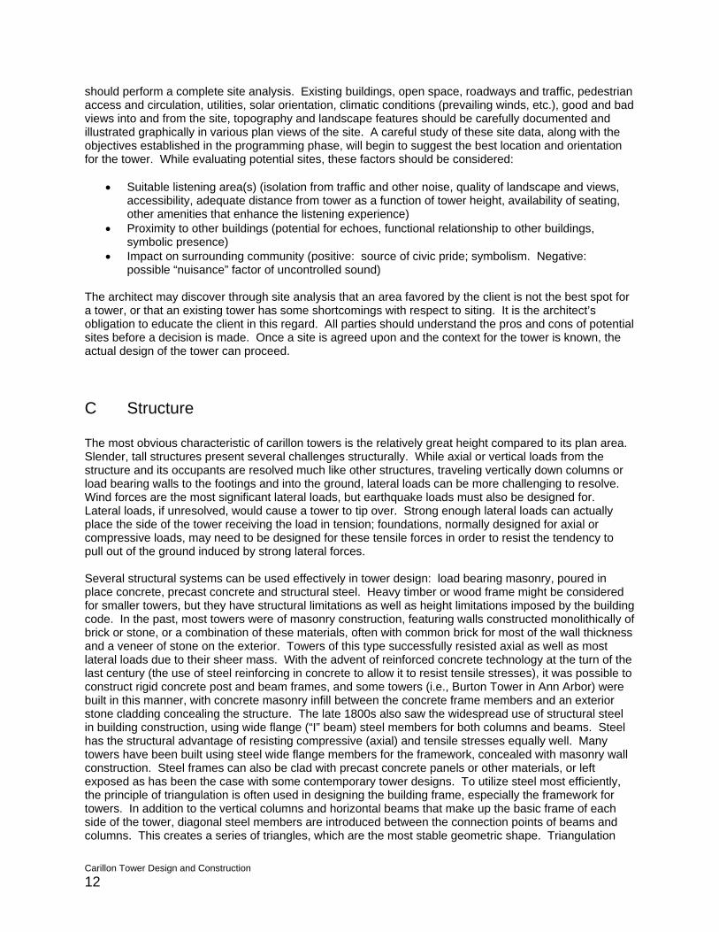
allows the least amount of steel to be used to resist the axial and lateral forces acting on the structure. Each wall of the tower in effect becomes a large vertical truss. As noted above, steel can be clad with a variety of exterior materials, or left exposed to become a feature of the design. Where steel is clad with masonry or covered in such a way that access for maintenance in the future is not possible, it should be hot-dipped galvanized to prevent corrosion and rust. This applies as well to secondary steel members such as shelf or relief angles that support masonry veneers.
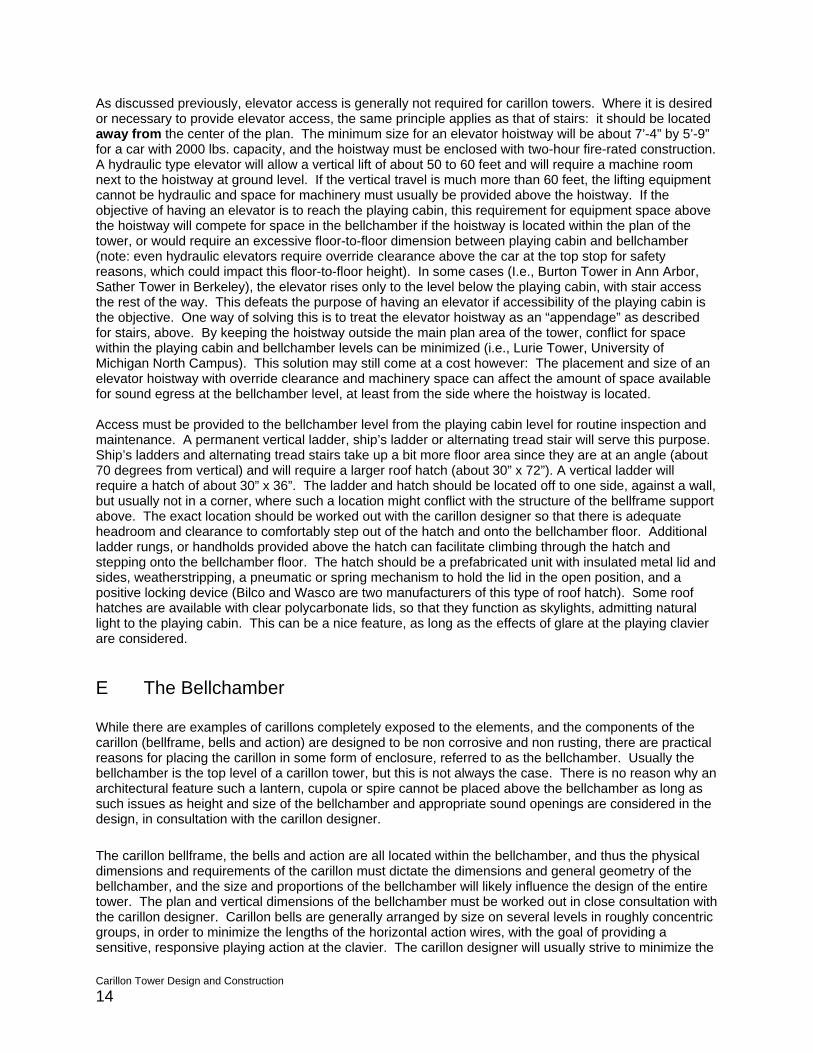
Exterior view, St. Mary’s of Redford, Detroit. An example of load bearing masonry construction with granite and limestone exterior.
D Access Stairway access is required to all leveplaying cabin. The bellchamber, whicarea but which does required servicin The type, size and number of stairs dGenerally, this will be less than 50 peless than 5, a spiral stair may be permthe most compact and space-saving mcode. Whether the stair is spiral or thfrom the center of the floor plan in orplaying cabin. A spiral stair may be lomaximum amount of space free in therun stair will require landings for everdirection at the landings, and the runsno less than 6 feet wide. This may cosuch cases, it is possible to arrange tin the corners. Thus, only a three-fooleaving the maximum available spacethe stair as an “appendage” to the maopenings.
Carillon Tower Design and Construction 13
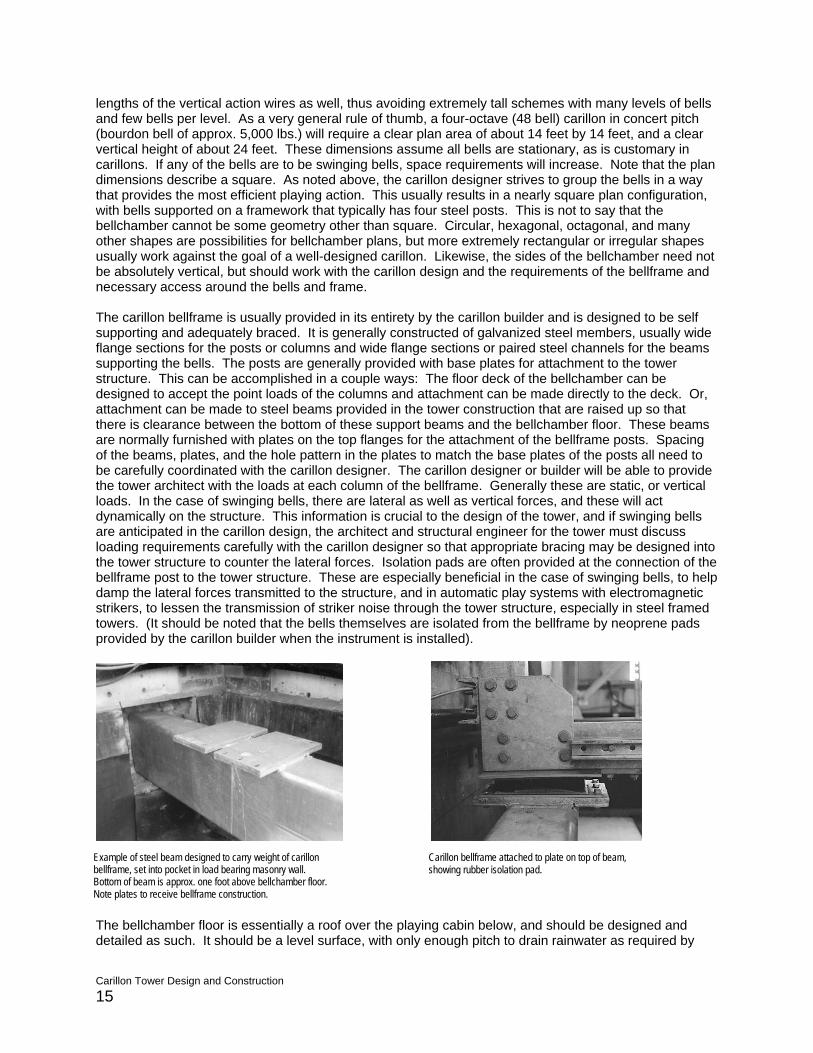
Interior view, St. Mary’s of Redford, Detroit. Common brick used in masonry load bearing construction. Walls are over two feet thick. Note also spiral stair access.
St. Hugo, Bloomfield Hills. Steel frame prior to installation of stone cladding. Note diagonal cross bracing.
ls of a tower that is designed for human occupation, including the h for code purposes is not considered a habitable or occupiable g, may be accessed by means of a ladder.
epend on the number of occupants anticipated for the tower. rsons, and one stair will be sufficient. If the number of occupants is itted. A spiral stair will be about 5 feet in diameter, and is probably ethod of providing stairway access that complies with the building
e more conventional straight-run type, it should be located away der to not conflict with the location of the playing clavier in the cated in a corner of the plan or centered on one side, keeping the center of the plan for the clavier. It should be noted that a straight-
y 12 feet of vertical rise. If the stair runs are parallel, reversing are 3 feet wide (the minimum allowable by code), the stair will be mpete with the clavier for space in towers with a small plan area. In
he stair along all four of the exterior walls, with intermediate landings t width is subtracted equally from all four sides of the plan area, in the center of the plan for the clavier. It is also possible to design in tower structure, leaving the floor plan unencumbered by stair
As discussed previously, elevator access is generally not required for carillon towers. Where it is desired or necessary to provide elevator access, the same principle applies as that of stairs: it should be located away from the center of the plan. The minimum size for an elevator hoistway will be about 7’-4” by 5’-9” for a car with 2000 lbs. capacity, and the hoistway must be enclosed with two-hour fire-rated construction. A hydraulic type elevator will allow a vertical lift of about 50 to 60 feet and will require a machine room next to the hoistway at ground level. If the vertical travel is much more than 60 feet, the lifting equipment cannot be hydraulic and space for machinery must usually be provided above the hoistway. If the objective of having an elevator is to reach the playing cabin, this requirement for equipment space above the hoistway will compete for space in the bellchamber if the hoistway is located within the plan of the tower, or would require an excessive floor-to-floor dimension between playing cabin and bellchamber (note: even hydraulic elevators require override clearance above the car at the top stop for safety reasons, which could impact this floor-to-floor height). In some cases (I.e., Burton Tower in Ann Arbor, Sather Tower in Berkeley), the elevator rises only to the level below the playing cabin, with stair access the rest of the way. This defeats the purpose of having an elevator if accessibility of the playing cabin is the objective. One way of solving this is to treat the elevator hoistway as an “appendage” as described for stairs, above. By keeping the hoistway outside the main plan area of the tower, conflict for space within the playing cabin and bellchamber levels can be minimized (i.e., Lurie Tower, University of Michigan North Campus). This solution may still come at a cost however: The placement and size of an elevator hoistway with override clearance and machinery space can affect the amount of space available for sound egress at the bellchamber level, at least from the side where the hoistway is located. Access must be provided to the bellchamber level from the playing cabin level for routine inspection and maintenance. A permanent vertical ladder, ship’s ladder or alternating tread stair will serve this purpose. Ship’s ladders and alternating tread stairs take up a bit more floor area since they are at an angle (about 70 degrees from vertical) and will require a larger roof hatch (about 30” x 72”). A vertical ladder will require a hatch of about 30” x 36”. The ladder and hatch should be located off to one side, against a wall, but usually not in a corner, where such a location might conflict with the structure of the bellframe support above. The exact location should be worked out with the carillon designer so that there is adequate headroom and clearance to comfortably step out of the hatch and onto the bellchamber floor. Additional ladder rungs, or handholds provided above the hatch can facilitate climbing through the hatch and stepping onto the bellchamber floor. The hatch should be a prefabricated unit with insulated metal lid and sides, weatherstripping, a pneumatic or spring mechanism to hold the lid in the open position, and a positive locking device (Bilco and Wasco are two manufacturers of this type of roof hatch). Some roof hatches are available with clear polycarbonate lids, so that they function as skylights, admitting natural light to the playing cabin. This can be a nice feature, as long as the effects of glare at the playing clavier are considered. E The Bellchamber While there are examples of carillons completely exposed to the elements, and the components of the carillon (bellframe, bells and action) are designed to be non corrosive and non rusting, there are practical reasons for placing the carillon in some form of enclosure, referred to as the bellchamber. Usually the bellchamber is the top level of a carillon tower, but this is not always the case. There is no reason why an architectural feature such a lantern, cupola or spire cannot be placed above the bellchamber as long as such issues as height and size of the bellchamber and appropriate sound openings are considered in the design, in consultation with the carillon designer. The carillon bellframe, the bells and action are all located within the bellchamber, and thus the physical dimensions and requirements of the carillon must dictate the dimensions and general geometry of the bellchamber, and the size and proportions of the bellchamber will likely influence the design of the entire tower. The plan and vertical dimensions of the bellchamber must be worked out in close consultation with the carillon designer. Carillon bells are generally arranged by size on several levels in roughly concentric groups, in order to minimize the lengths of the horizontal action wires, with the goal of providing a sensitive, responsive playing action at the clavier. The carillon designer will usually strive to minimize the
Carillon Tower Design and Construction 14
lengths of the vertical action wires as well, thus avoiding extremely tall schemes with many levels of bells and few bells per level. As a very general rule of thumb, a four-octave (48 bell) carillon in concert pitch (bourdon bell of approx. 5,000 lbs.) will require a clear plan area of about 14 feet by 14 feet, and a clear vertical height of about 24 feet. These dimensions assume all bells are stationary, as is customary in carillons. If any of the bells are to be swinging bells, space requirements will increase. Note that the plan dimensions describe a square. As noted above, the carillon designer strives to group the bells in a way that provides the most efficient playing action. This usually results in a nearly square plan configuration, with bells supported on a framework that typically has four steel posts. This is not to say that the bellchamber cannot be some geometry other than square. Circular, hexagonal, octagonal, and many other shapes are possibilities for bellchamber plans, but more extremely rectangular or irregular shapes usually work against the goal of a well-designed carillon. Likewise, the sides of the bellchamber need not be absolutely vertical, but should work with the carillon design and the requirements of the bellframe and necessary access around the bells and frame. The carillon bellframe is usually provided in its entirety by the carillon builder and is designed to be self supporting and adequately braced. It is generally constructed of galvanized steel members, usually wide flange sections for the posts or columns and wide flange sections or paired steel channels for the beams supporting the bells. The posts are generally provided with base plates for attachment to the tower structure. This can be accomplished in a couple ways: The floor deck of the bellchamber can be designed to accept the point loads of the columns and attachment can be made directly to the deck. Or, attachment can be made to steel beams provided in the tower construction that are raised up so that there is clearance between the bottom of these support beams and the bellchamber floor. These beams are normally furnished with plates on the top flanges for the attachment of the bellframe posts. Spacing of the beams, plates, and the hole pattern in the plates to match the base plates of the posts all need to be carefully coordinated with the carillon designer. The carillon designer or builder will be able to provide the tower architect with the loads at each column of the bellframe. Generally these are static, or vertical loads. In the case of swinging bells, there are lateral as well as vertical forces, and these will act dynamically on the structure. This information is crucial to the design of the tower, and if swinging bells are anticipated in the carillon design, the architect and structural engineer for the tower must discuss loading requirements carefully with the carillon designer so that appropriate bracing may be designed into the tower structure to counter the lateral forces. Isolation pads are often provided at the connection of the bellframe post to the tower structure. These are especially beneficial in the case of swinging bells, to help damp the lateral forces transmitted to the structure, and in automatic play systems with electromagnetic strikers, to lessen the transmission of striker noise through the tower structure, especially in steel framed towers. (It should be noted that the bells themselves are isolated from the bellframe by neoprene pads provided by the carillon builder when the instrument is installed).
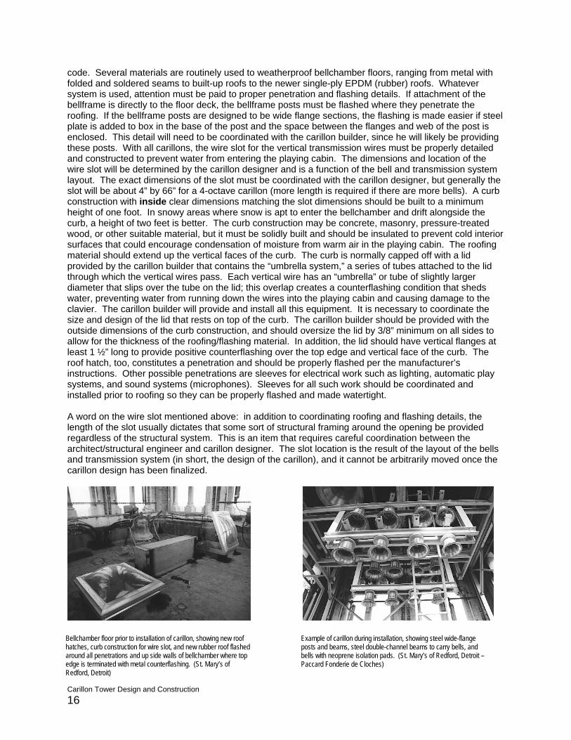
Example of steel beam designed to carry weight of carillon bellframe, set into pocket in load bearing masonry wall. Bottom of beam is approx. one foot above bellchamber floor. Note plates to receive bellframe construction.
Carillon bellframe attached to plate on top of beam, showing rubber isolation pad.
The bellchamber floor is essentially a roof over the playing cabin below, and should be designed and detailed as such. It should be a level surface, with only enough pitch to drain rainwater as required by
Carillon Tower Design and Construction 15
code. Several materials are routinely used to weatherproof bellchamber floors, ranging from metal with folded and soldered seams to built-up roofs to the newer single-ply EPDM (rubber) roofs. Whatever system is used, attention must be paid to proper penetration and flashing details. If attachment of the bellframe is directly to the floor deck, the bellframe posts must be flashed where they penetrate the roofing. If the bellframe posts are designed to be wide flange sections, the flashing is made easier if steel plate is added to box in the base of the post and the space between the flanges and web of the post is enclosed. This detail will need to be coordinated with the carillon builder, since he will likely be providing these posts. With all carillons, the wire slot for the vertical transmission wires must be properly detailed and constructed to prevent water from entering the playing cabin. The dimensions and location of the wire slot will be determined by the carillon designer and is a function of the bell and transmission system layout. The exact dimensions of the slot must be coordinated with the carillon designer, but generally the slot will be about 4” by 66” for a 4-octave carillon (more length is required if there are more bells). A curb construction with inside clear dimensions matching the slot dimensions should be built to a minimum height of one foot. In snowy areas where snow is apt to enter the bellchamber and drift alongside the curb, a height of two feet is better. The curb construction may be concrete, masonry, pressure-treated wood, or other suitable material, but it must be solidly built and should be insulated to prevent cold interior surfaces that could encourage condensation of moisture from warm air in the playing cabin. The roofing material should extend up the vertical faces of the curb. The curb is normally capped off with a lid provided by the carillon builder that contains the “umbrella system,” a series of tubes attached to the lid through which the vertical wires pass. Each vertical wire has an “umbrella” or tube of slightly larger diameter that slips over the tube on the lid; this overlap creates a counterflashing condition that sheds water, preventing water from running down the wires into the playing cabin and causing damage to the clavier. The carillon builder will provide and install all this equipment. It is necessary to coordinate the size and design of the lid that rests on top of the curb. The carillon builder should be provided with the outside dimensions of the curb construction, and should oversize the lid by 3/8” minimum on all sides to allow for the thickness of the roofing/flashing material. In addition, the lid should have vertical flanges at least 1 ½” long to provide positive counterflashing over the top edge and vertical face of the curb. The roof hatch, too, constitutes a penetration and should be properly flashed per the manufacturer’s instructions. Other possible penetrations are sleeves for electrical work such as lighting, automatic play systems, and sound systems (microphones). Sleeves for all such work should be coordinated and installed prior to roofing so they can be properly flashed and made watertight. A word on the wire slot mentioned above: in addition to coordinating roofing and flashing details, the length of the slot usually dictates that some sort of structural framing around the opening be provided regardless of the structural system. This is an item that requires careful coordination between the architect/structural engineer and carillon designer. The slot location is the result of the layout of the bells and transmission system (in short, the design of the carillon), and it cannot be arbitrarily moved once the carillon design has been finalized.
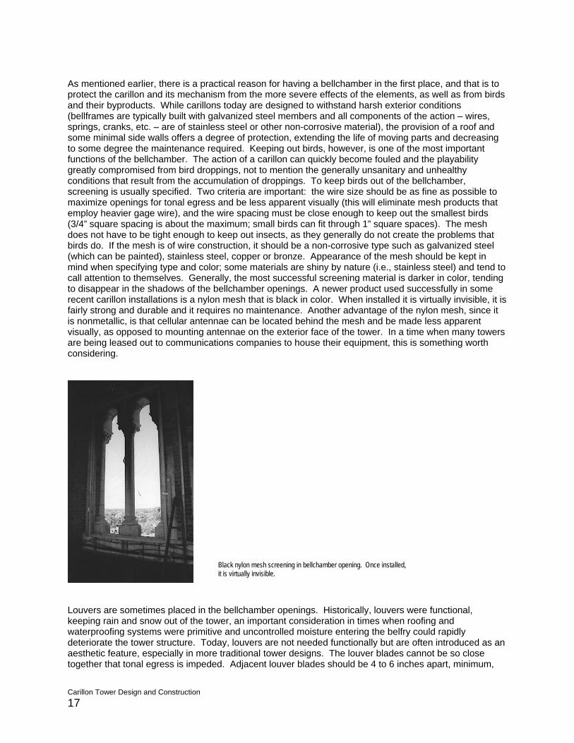
Bellchamber floor prior to installation of carillon, showing new roof hatches, curb construction for wire slot, and new rubber roof flashed around all penetrations and up side walls of bellchamber where top edge is terminated with metal counterflashing. (St. Mary’s of Redford, Detroit)
Example of carillon during installation, showing steel wide-flange posts and beams, steel double-channel beams to carry bells, and bells with neoprene isolation pads. (St. Mary’s of Redford, Detroit – Paccard Fonderie de Cloches)
Carillon Tower Design and Construction 16
As mentioned earlier, there is a practical reason for having a bellchamber in the first place, and that is to protect the carillon and its mechanism from the more severe effects of the elements, as well as from birds and their byproducts. While carillons today are designed to withstand harsh exterior conditions (bellframes are typically built with galvanized steel members and all components of the action – wires, springs, cranks, etc. – are of stainless steel or other non-corrosive material), the provision of a roof and some minimal side walls offers a degree of protection, extending the life of moving parts and decreasing to some degree the maintenance required. Keeping out birds, however, is one of the most important functions of the bellchamber. The action of a carillon can quickly become fouled and the playability greatly compromised from bird droppings, not to mention the generally unsanitary and unhealthy conditions that result from the accumulation of droppings. To keep birds out of the bellchamber, screening is usually specified. Two criteria are important: the wire size should be as fine as possible to maximize openings for tonal egress and be less apparent visually (this will eliminate mesh products that employ heavier gage wire), and the wire spacing must be close enough to keep out the smallest birds (3/4” square spacing is about the maximum; small birds can fit through 1” square spaces). The mesh does not have to be tight enough to keep out insects, as they generally do not create the problems that birds do. If the mesh is of wire construction, it should be a non-corrosive type such as galvanized steel (which can be painted), stainless steel, copper or bronze. Appearance of the mesh should be kept in mind when specifying type and color; some materials are shiny by nature (i.e., stainless steel) and tend to call attention to themselves. Generally, the most successful screening material is darker in color, tending to disappear in the shadows of the bellchamber openings. A newer product used successfully in some recent carillon installations is a nylon mesh that is black in color. When installed it is virtually invisible, it is fairly strong and durable and it requires no maintenance. Another advantage of the nylon mesh, since it is nonmetallic, is that cellular antennae can be located behind the mesh and be made less apparent visually, as opposed to mounting antennae on the exterior face of the tower. In a time when many towers are being leased out to communications companies to house their equipment, this is something worth considering.
Black nylon mesh screening in bellchamber opening. Once installed, it is virtually invisible.
Louvers are sometimes placed in the bellchamber openings. Historically, louvers were functional, keeping rain and snow out of the tower, an important consideration in times when roofing and waterproofing systems were primitive and uncontrolled moisture entering the belfry could rapidly deteriorate the tower structure. Today, louvers are not needed functionally but are often introduced as an aesthetic feature, especially in more traditional tower designs. The louver blades cannot be so close together that tonal egress is impeded. Adjacent louver blades should be 4 to 6 inches apart, minimum,
Carillon Tower Design and Construction 17
for good tonal egress. Louvers alone are not sufficient to keep birds out, and screening as described above must be provided behind the louvers. Louvers provide additional surface area within the bellchamber to reflect bell sounds, resulting in a blended sound leaving the bellchamber through the spaces between the louver blades (some carillon playing techniques, such as tremolandi, exploit this phenomenon: rapidly repeated notes seem to merge into a continuous uninterrupted sound). To some extent, louvers may direct sound downwards, due to the angled orientation of the louver blades, but there are many examples of towers with louvered openings in which the sound travels great distances, seemingly unimpeded by the louvers. This may be because sound is not merely reflected downward off the backside of the louver blades, but actually reflected twice, first downward off the back of a blade and then outward off the face of the blade below. The size and configuration of the bellchamber openings is critical to the success of the carillon, which is, after all, a musical instrument. Openings that are too small or poorly placed can severely compromise the sound of the carillon. A good average percentage of open wall area is 60%. This percentage should generally be higher (70%) for taller towers and a bit less (40-50%) for lower towers. In lower towers, where listeners are likely to be closer to the bells, the lesser amount of opening will help to provide blend and balance to the carillon. Carrying power of the carillon will be less, but this is not critical when the listeners are close to the tower. In higher towers, and in situations where the listeners will be some distance from the tower, a greater amount of opening will permit greater tonal egress of the bell sounds. In all cases, some degree of enclosure is desirable for proper blending and balance of the carillon. The openings should be equally distributed among the sides of the bellchamber so that tonal egress is equal in all directions, unless there is a need to control the amount of sound in a particular direction, in which case the openings may be arranged asymmetrically as dictated by design and site constraints. The sill of the openings should be fairly close to the bellchamber floor, just high enough to properly flash the roofing of the bellchamber floor. It is important that the sill of the openings be kept below the bottom edge or lip of the lowest bells for proper tonal egress. The height of the bellchamber and the tops of the openings should be established in response to the design of the carillon. The height of the openings should be equal to the height of the highest bells in the bellframe, and an additional 2 to 3 feet should be provided above the bellframe for ease of movement during inspection and maintenance. The top or ceiling of the bellchamber, thus established, should be reflective in character, in order to conserve and reflect the sounds of the bells (especially of the trebles) to the ground. Extending the height of the bellchamber and the openings above the top of the bellframe greater than a couple feet as described does not provide any acoustical advantage and in fact can be detrimental to the sound of the carillon; the higher the ceiling above the carillon, the less effective it will be as a reflector. Finally, the design of the bellchamber should anticipate the method and sequence of installation of the carillon. Most carillons today are installed by crane, lifting material up from a point next to the tower and bringing it in through the side openings or possibly from overhead if part of the structure is left off temporarily. If the carillon is to be installed through the openings, the architect must know what the largest component (usually the largest bell) will be and plan accordingly. It is possible to leave out some of the wall framing and finish material in order to accommodate larger components and finish this work after the carillon has been installed. It is generally not a good idea, however, to sequence the carillon installation in a way that requires substantial construction of the bellchamber after the instrument has been hoisted and assembled. The activity of the many tradesmen that would be required to finish the construction of the bellchamber in this situation is likely to cause damage to the carillon. Where it is not feasible to use a crane for the carillon installation, it is possible to make provisions within the tower for hoisting material up through the tower. A hoisting beam designed to carry the weight of the largest bell (approx. 5,000 lbs. for a bourdon of C) would need to be installed as part of the tower structure at the ceiling level of the bellchamber. Openings of approx. 6 feet square would need to be provided at each floor level within the tower, and a doorway or temporary opening of sufficient width provided at the ground level. In this way, all the parts of the carillon could be hoisted up through the center of the tower and the floor opening filled in after the carillon is completed.
Carillon Tower Design and Construction 18
F The Playing Cabin A true carillon of cast bronze bells is manually played from a clavier or keyboard that is connected by means of transmission wires to the clappers of the bells. The clavier is housed in the playing cabin, a room that must be designed to protect the clavier from the elements and provide a degree of comfort to the carillonneur as he or she plays the instrument. The playing cabin is located directly below the bellchamber so the clavier can be placed in the optimum position relative to the transmission system. Most carillons utilize a central transmission design, whereby wires from the bell clappers converge in a central location and by means of cranks or squares are translated to a series of vertical wires. These vertical wires are parallel and spaced according to the key spacing of the clavier. These wires must be maintained in perfect vertical alignment. The location of the wire slot (see above) and the location of the clavier in the playing cabin are established by the design of the transmission system. Other elements of the playing cabin such as stairs, hatch and ladder to bellchamber, windows, heating and ventilation systems and lighting all must relate to the placement of the clavier, and thus the location of the clavier must be established early on in conjunction with the carillon designer in order for the design of the tower as a whole to proceed. The floor area of the playing cabin may encompass the entire area to the outside walls of the tower, but may literally be a small room with its own exterior walls, set away from the actual tower walls, just sufficient in area for the clavier, bench and room to move around and service the clavier. This smallest possible configuration is suitable only when it is expected that the carillonneur will be the only person in the playing cabin. If there is the possibility of visitors or if teaching will take place at the carillon, more room should be provided in the playing cabin. In all cases, several feet of space should be provided to service the clavier from the back and both sides. Some space should also be provided behind the bench, so the carillonneur may adjust the bench closer or farther from the clavier as needed. The ceiling height of the playing cabin should be around 8 feet; much less can become claustrophobic and much more unnecessarily lengthens the vertical transmission wires, which the carillon designer will attempt to keep as short as possible in order to produce the most responsive playing action. Whether the floor of the playing cabin is steel framed with concrete on metal deck, wood framed with wood subfloor, or poured in place concrete, it must be designed to be absolutely rigid, with no deflection, in order for the clavier to be perfectly stable (any movement in the floor due to deflection will be communicated through the clavier to the transmission wires, affecting the playing action of the carillon). Chapter 12 of the Building Code, discussed above, gives minimum requirements for ventilation, heating and lighting of spaces intended for human occupancy. Meeting these minimum requirements may not be adequate to provide a good working environment for the carillonneur. The code calls for maintaining 68 degrees F in the space but does not define specific methods. Some heating equipment utilizes fan blowers that can be noisy and create unwanted drafts that can disturb the carillonneur or blow music off the rack. Heating units that operate with a low noise level should be specified, and units (or diffusers if ducted) should be located so that air is not blown directly onto the carillonneur when seated at the bench, or onto the music rack. The code does not specifically call for air conditioning, but most parts of the country have summertime weather that is hot and humid enough that the comfort of a performing carillonneur would be greatly enhanced if air conditioning is provided. As with heating systems, noise levels and how and where the air is distributed in the space should be considered. Absent air conditioning, proper ventilation is essential. The code-required 4 percent of floor area would be inadequate to provide comfort to the carillonneur. Openings, by means of windows and roof hatches, should be provided such that good cross ventilation is possible, but controllable to avoid drafts. In addition, the provision of windows in the playing cabin and/or hatches with skylight glazing creates an opportunity to enhance the environment with natural light and views from the tower. One must be careful, however, in the placement of windows and skylights. Glare must be avoided in the eyes of the carillonneur while seated at the clavier. Shades or other devices may need to be installed to control sources of natural light and mitigate glare. The code requirement of 10 footcandles of artificial light at a height of 30 inches above the floor will not be adequate for reading music at the clavier. A better lighting level would be 25 to 50 footcandles measured at the music rack. General illumination in the cabin should be such that the pedal board can be easily seen also. Lighting should be placed above and slightly behind the plane of the music rack so that the area receives even illumination without shadow, and without glare in the eyes of the carillonneur. Flourescent lighting with parabolic lenses provides good,
Carillon Tower Design and Construction 19
even illumination without glare, and incandescent or halogen track lighting has been used successfully in some towers, with the added benefit of adjustability. Some lighting, especially incandescent and halogen light sources, can produce a fair amount of heat, and should be located and ventilated so that the comfort of the carillonneur is maintained. Another important factor in the design of the playing cabin is enabling the carillonneur to hear the instrument when he or she is playing. The most direct way is to provide openings (windows, doors, hatches) that can be opened in a controlled manner to permit the sound of the bells to enter the cabin. The hatch provided for access to the bellchamber, discussed above, can be used for this function, if it is so located with respect to the bellframe that no single bell is located too close to the hatch, and the sound reaching the carillonneur is balanced. Provision of a second hatch into the playing cabin can also help provide a more balanced sound. Control of the hatch lid is essential in order to control the volume of sound entering the cabin; this can be achieved with a device as simple as rope tied to the hatch handle, permitting opening, closing, or any degree of adjustment in between. Electric motor operators for the hatches are another option if manual control is not feasible. Windows, while admitting some sound, are not as effective as hatches opening directly into the bellchamber, especially if the outside walls of the playing cabin are the same as the outside walls of the bellchamber; sound exits the bellchamber at an angle, with very little sound radiating downward vertically at the face of the tower and into an open window. There may be times of the year when it is too cold to open hatches, doors or windows to hear the bells. A good sound monitoring system, with several microphones strategically placed in the bellchamber and amplifier and speakers in the playing cabin, should be part of the tower design in order for the carillonneur to hear the instrument in all weather conditions. As noted above, ambient noise from heating, ventilating and air conditioning equipment must be kept at a low level in order to hear the instrument properly. Once proper provisions for the clavier, the comfort of the carillonneur and hearing the bells have been established in the cabin design, these additional functional requirements should be considered:
• Communication: a telephone extension or intercom allowing communication with someone on the ground.
• Coat hooks: a place to hang up coats, sweaters, etc. • Counter or shelf space for audio equipment • Counter or shelf space for water bottles, drinks, backpacks, music (the edge of the bench is not
the best place to be putting these things) • Seating, if it is intended that persons other that the carillonneur will be in the playing cabin.
The preceding discussion has assumed an ample playing cabin with a floor area equal to the plan dimensions of a moderately sized tower, and a carillon of four octaves. In some instances, especially where the carillon exceeds 4 octaves, and the range extends below the normal C bourdon bell of approximately 5,000 lbs., it is advantageous to arrange the bells in such a way that the larger bells are below the playing cabin, with the rest of the bells above the cabin. There are also examples of towers in which the playing cabin is literally a small room at the level of the bellchamber floor, with the bells around and above the cabin. The carillon designer may suggest such configurations, especially for larger instruments, to keep transmission wires as short as possible and thus improve the responsiveness of the instruments, as well as to permit a more balanced perception of the bells by the player. While the floor area of the playing cabin may be limited in these situations, the points discussed above with regard to environment and comfort still apply. Access to a playing cabin situated among the bells or at the level of the bellchamber floor will need to be carefully coordinated with the carillon designer, so that stairs do not conflict with the bellframe and bell layout.
Carillon Tower Design and Construction 20
G Adapting Existing Towers There are many examples of existing towers containing one or several swinging bells, or perhaps a chime, that have been adapted and equipped with carillons. The following items should be carefully researched and considered to determine the suitability of an existing tower to house a carillon:
• Dimensions of the tower. The plan dimensions and height of the bellchamber should be accurately measured to determine if there are minimum space requirements for a carillon bellframe and room for installation and servicing (refer to discussion above under “Bellchamber”). If space is lacking for a full size (4 octave or larger) instrument in concert pitch, it may be possible to install an instrument of fewer bells and/or an instrument at a higher pitch. Involvement of a carillon consultant or carillon builder/bellfounder at this point will help one quickly determine the potential of an existing tower.
• Structure of the tower. Many older towers of solid masonry construction are structurally “overbuilt” and have capacity in the wall construction to take the weight of a carillon. It is also possible that towers of other types of construction (concrete or steel frame) may have the capacity for additional load. A structural engineer can measure wall thickness, observe sizes of structural members, thicknesses of floor slabs, etc., and be able to analyze the structural capacity of the tower. If construction drawings of the tower are available, they can be of great help in this analysis. With the advice of a carillon consultant or carillon builder/bellfounder, the proposed weight of the carillon (bells, bellframe, action, etc.) is given to the structural engineer, who can then determine if the tower is structurally adequate to house a carillon. Unless the tower was built with specific provisions for a future carillon, it is unlikely the floor of the bellchamber will be able to take the concentrated loads of the bellframe posts. In existing masonry towers, it is usually an easy matter to provide a pair of beams bearing in pockets cut in the masonry walls inside the bellchamber, with the bottom of the beams a foot or so above the floor of the bellchamber. The posts of the carillon bellframe are attached to these new beams, and the load of the carillon is transferred to the masonry walls of the tower (refer to illustration above). In towers of concrete or steel construction, it may be possible to add steel framing and/or reinforce existing beams and columns to take the weight of a carillon. Provision must also be made in the bellchamber floor for the wire slot and an access hatch (the latter most likely already exists and if properly sized and located with respect to the proposed carillon, may remain in place). The location of the wire slot for the vertical transmission wires of the carillon will be determined by the carillon builder and is a function of the carillon design (see discussion above under “Bellchamber”). Depending on how the bellchamber floor is constructed and framed, it may be necessary to locate the wire slot to one side or another of an existing steel, wood or concrete beam, which may place the wire slot slightly off center; the carillon builder should work in consultation with the structural engineer to determine what is possible in terms of modifying and adding framing to provide the slot in the most advantageous location. In the case of steel or wood framed floors, it is usually possible to add framing members and reinforce existing members where necessary in such a way that the wire slot is supported on all sides, allowing the hole to be cut in the floor. In the case of poured-in-place concrete floors, it is generally not possible to cut through the floor without first adding framing from underneath to support the opening on all sides, because concrete slabs contain steel reinforcing bars at regularly spaced intervals (4 to 6 inches on center, often in two perpendicular directions), and cutting through any of the bars will compromise the structural integrity of the slab. If hatches and other openings must be made in a concrete slab, it may be more cost effective to remove all of the slab right to the walls of the tower, or a portion of the slab if it frames into a center beam, and reframe and rebuild the bellchamber floor in steel or wood. If the structure of the bellchamber floor is such that two major beams are centered and perpendicular to one another, creating a cross pattern, It will be impossible to center the wire slot to one side or another of a beam without being bisected by the other beam. Because of the close spacing (approx. 1” on center) of the transmission wires, it is not possible to allow any structural member to interrupt the wire slot. In this situation, it will be necessary to reconfigure the framing by adding structural members and/or reinforcing existing
Carillon Tower Design and Construction 21
members so that one of the two central beams can be removed, allowing the wire slot to be centrally located.
• General layout of the tower: How many floor levels does the tower have? Are there simply a ground level and a bellchamber level, or are there intervening floors? If there are several floors, is there a floor located about 8 to 10 feet below the bellchamber? A floor at this location will be necessary to create a playing cabin. If a floor exists but is more than 10 feet below the bellchamber floor, it is advisable to build a platform for the clavier in order to keep the length of the vertical transmission wires as short as possible. If no floor exists below the bellchamber, or if the floor is 16 feet or more below, it will be necessary to build a new floor 8 to 10 feet below the bellchamber. A structural engineer can suggest how this might best be done, working with the structure of the tower. Refer to discussion above (The Playing Cabin) for additional considerations for this space.
• Access: It is not unusual in existing towers (especially older ones) housing only a few swinging bells to have only ladder access to the bellchamber, intended to be used periodically for maintenance only. Stairways must be provided from the ground level to the playing cabin level. If an existing level is to be used for the playing cabin and it has a stairway to the ground floor, this may be sufficient provided the stair enters the playing cabin at a location that does not conflict with the proposed location of the clavier (if there is a conflict, it will be necessary to rework the stair and the floor opening into the playing cabin). If a new floor is to be built for the playing cabin, new stair construction must be added up to the new floor. Ladder and hatch access from the playing cabin level to the bellchamber must be provided, either existing as discussed above or relocated/new if required by the carillon and structural design.
• Electrical and mechanical services: Upgrading of electrical and mechanical systems will likely be required. Lighting must be provided at the stair and in the playing cabin. Convenience outlets should be provided in the playing cabin. Heating and ventilation (and possibly air conditioning) will need to be provided in the playing cabin. Additional electrical circuits may be required for automatic play systems, special lighting in the bellchamber, and other needs. A qualified engineer or contractor should be able to evaluate what is present in the tower and the extent of electrical and mechanical upgrades.
• Compliance with codes: Depending on the tower, the work required to prepare the tower for a carillon may be minimal or quite extensive. In any case, permits must be obtained from the Building Department by all the contractors who will be working in the tower, and it is likely drawings will need to be prepared by licensed professionals if the work is extensive. It is recommended that once one has determined the scope of work required, after having consulted with the carillon designer or consultant, the engineers and architect, and before expending time and money on construction documents, a meeting be set up with the local Code Official to discuss the project and to understand how the code will be applied.
Carillon Tower Design and Construction 22
3 Appendices Appendix A List of Bellfounders/Carillon Builders The Verdin Company 444 Reading Road Cincinnati, Ohio 45202-1432 (800) 543-0488 James R. Verdin The van Bergen Company P.O. Box 12928 Charleston, South Carolina 29422-2928 (800) 544-8820 Harry van Bergen U. S. Distributor for Paccard Fonderie de Cloches, Annecy, France Royal Eijsbouts Bellfounders P. O. Box 2, NL 5720 AA Asten, The Netherlands 31-493-691445 Joost Eijsbouts, Joep van Brussel Royal Bellfoundry Petit & Fritsen b.v. P.O. Box 2, 5735 ZG Aarle-Rixtel, The Netherlands 31-492-381-287 Henk Van Blooijs Meeks, Watson & Company P. O. Box 700 Georgetown, Ohio 45121 (800) 626-3067 Rick Watson, Bill Meeks John Taylor Bellfounders Ltd. The Bell Foundry Freehold Street Loughborough, Leics, LE11 1AR England 44-1509-212241 Alan Berry
Carillon Tower Design and Construction 23
Appendix B List of Carillon Consultants Note: The following list is given for general reference only and does not imply endorsement by the
GCNA, its Board or Officers. It is recommended that the individual contracting with a consultant review the qualifications and references of the consultant prior to entering into an agreement for consulting services.
John Gouwens c/o Culver Academies 1300 Academy Road, #133 Culver, Indiana 46511-1291 (574) 842-2183 Margo Halsted Professor and Carillonneur Emeritus The University of Michigan 330 East Cordova, #324 Pasadena, California 91101 (626) 792-4315 Karel J. Keldermans 7614 Noelsch Road Virginia, Illinois 62691-9752 (217) 753-6219
Carillon Tower Design and Construction 24
Appendix C Illustrations 1 Example Tower Elevation and Cross Section 2 Example Tower Plan A-A Ground Level and Plan B-B Playing Cabin Level 3 Example Tower Plan C-C First Level of Bells and Plan D-D Second Level of Bells 4 Example Tower Plan E-E Third Level of Bells and Plan F-F Fourth Level of Bells 5 Example Tower Cross Sections showing Stair Alternates One and Two 6 Example Tower Plan A-A Ground Level and Plan B-B Playing Cabin Level showing Alternate Stair One 7 Example Tower Plan A-A Ground Level and Plan B-B Playing Cabin Level showing Alternate Stair Two 8 Plan View Four Octave Carillon Keyboard 9 Plan View Five Octave Carillon Keyboard 10 Schematic Section of Louver 11 Cross Section Wire Slot/Umbrella Curb 12 Conventional Stairway Details 13 Spiral Stairway Details 14 Ladder Details
Carillon Tower Design and Construction 25
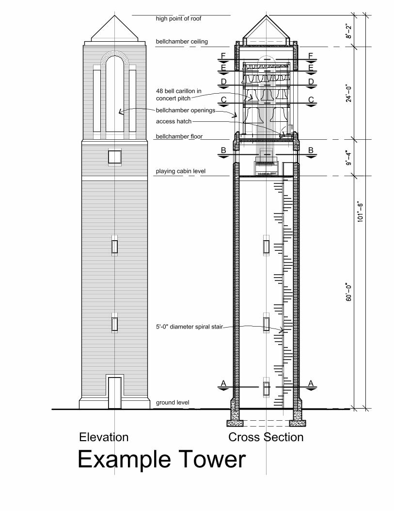
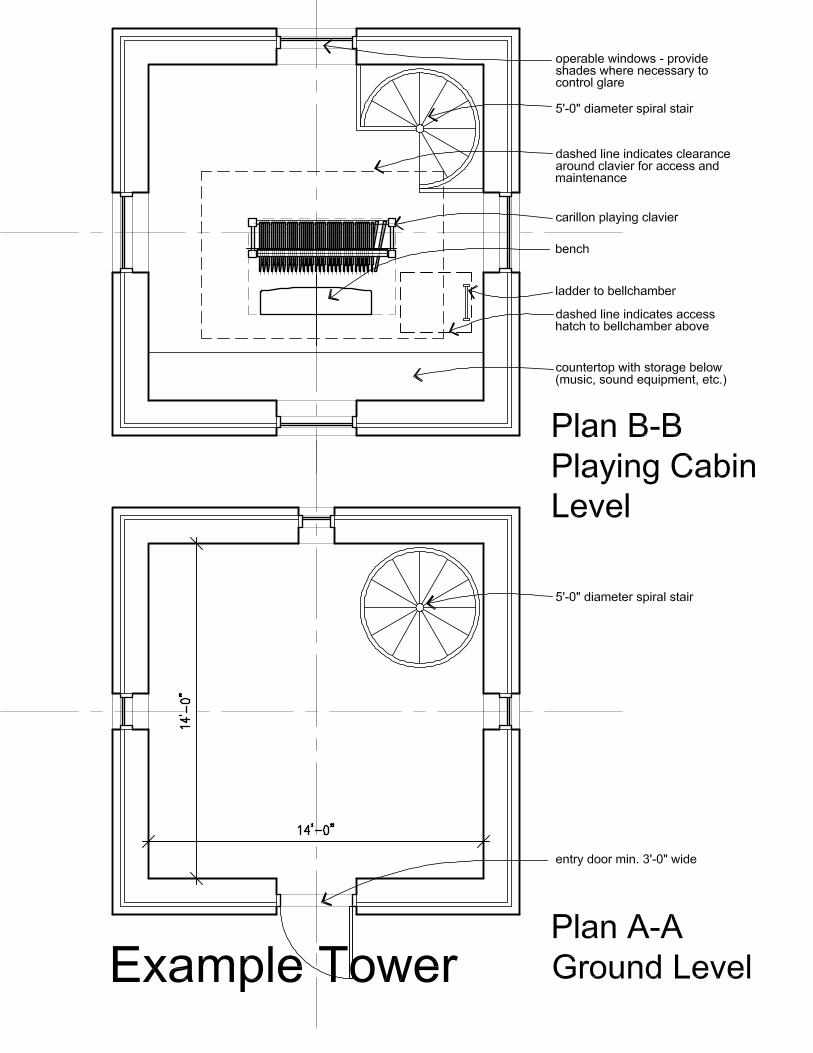
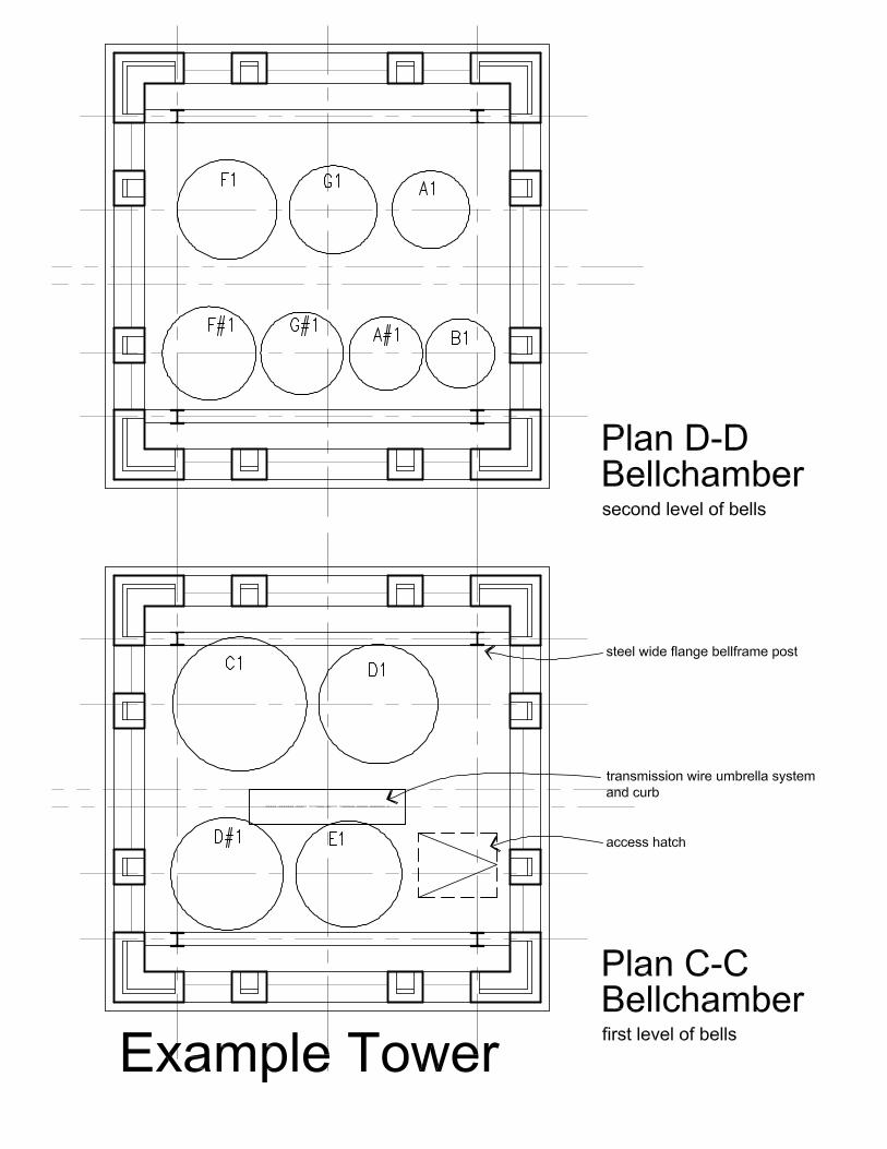
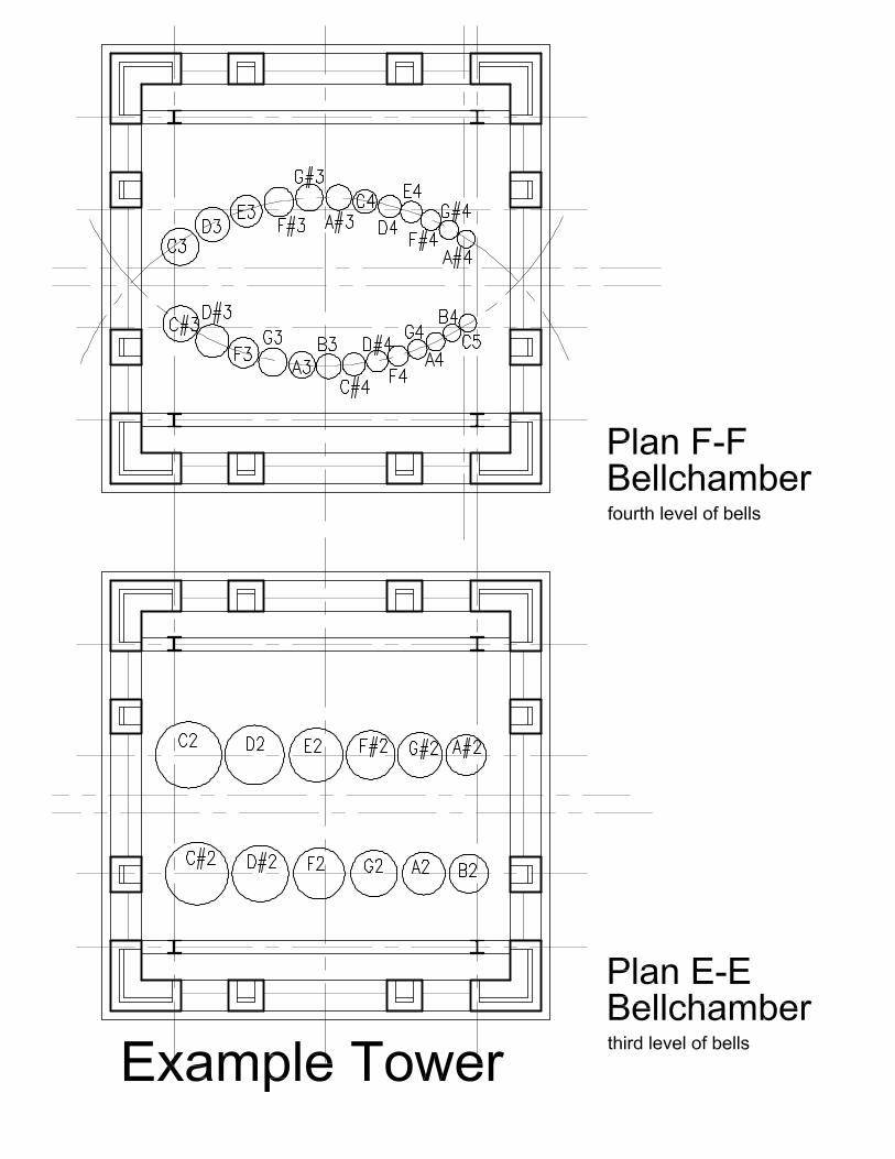
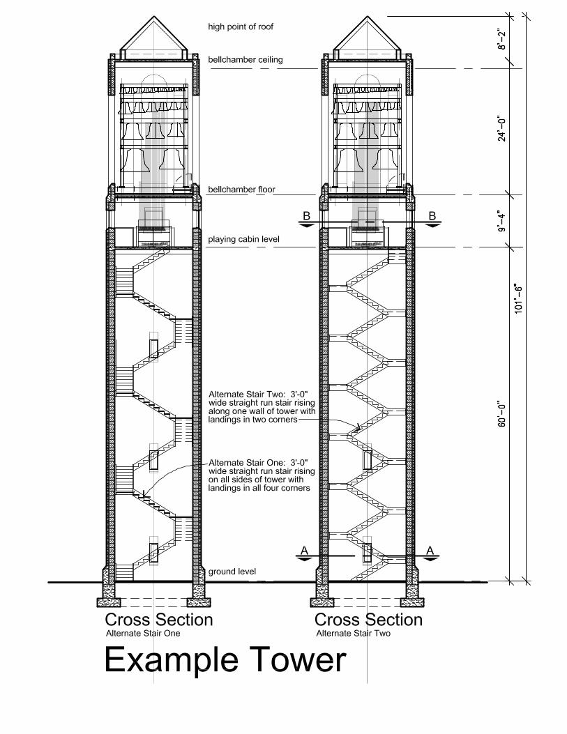
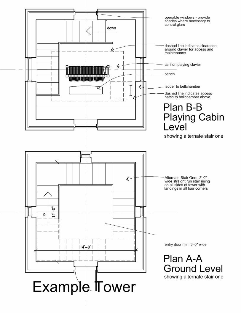
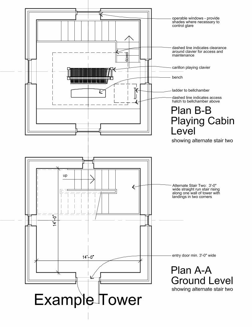
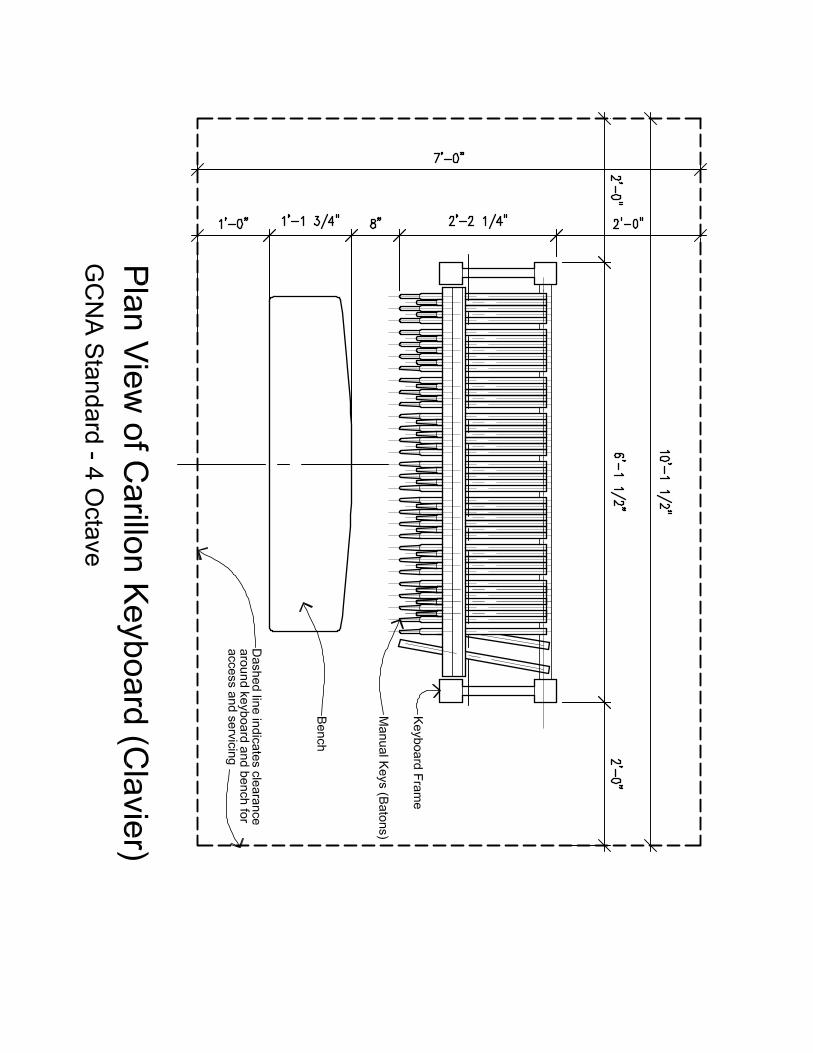
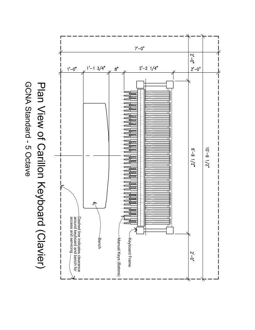
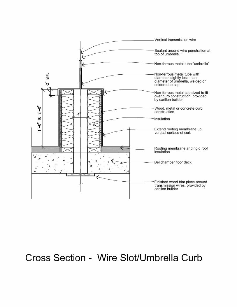
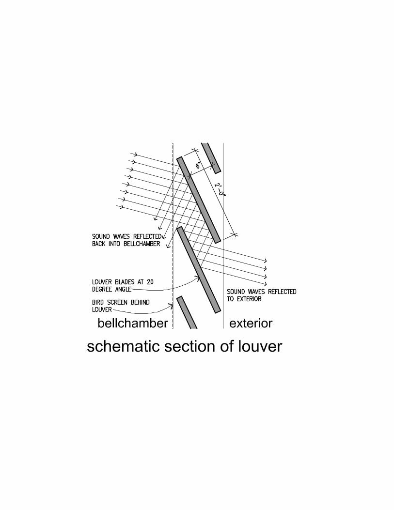
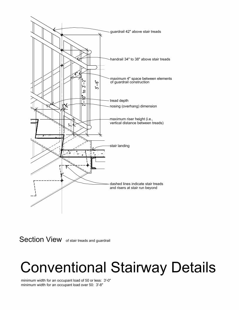
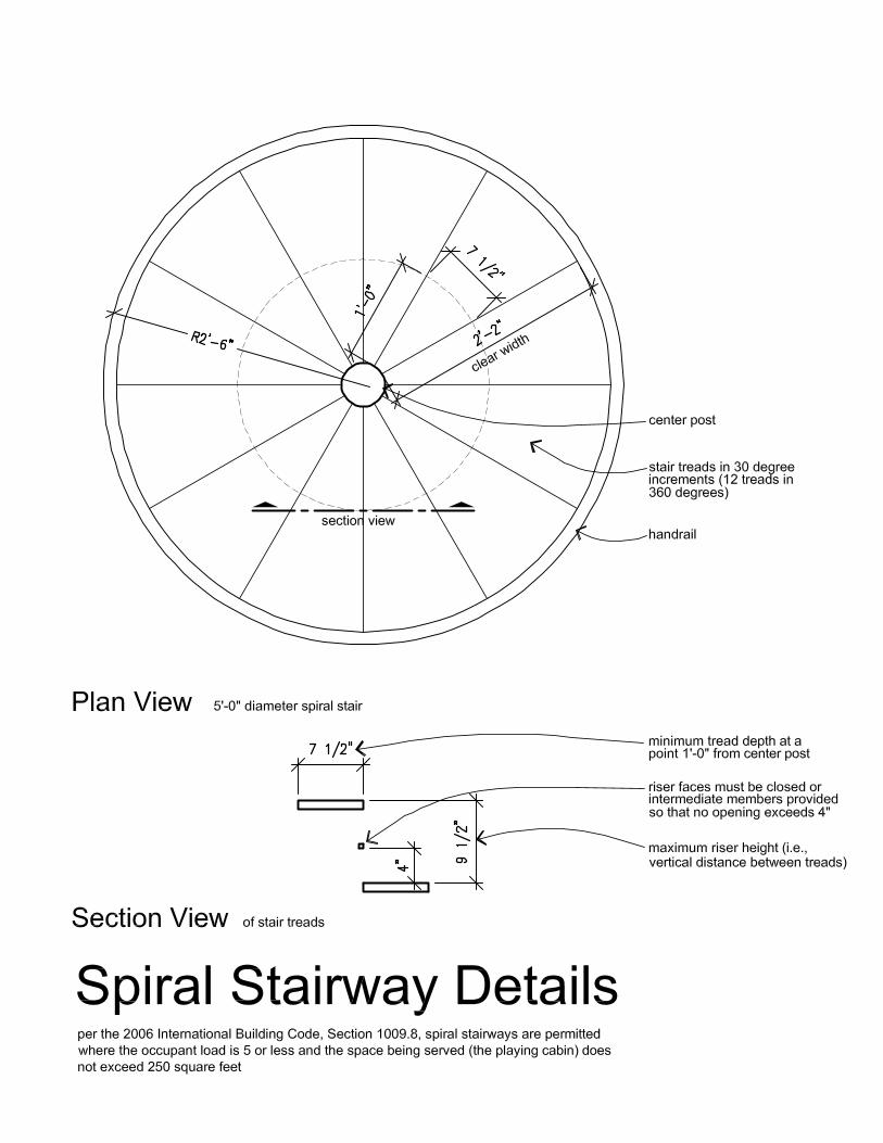
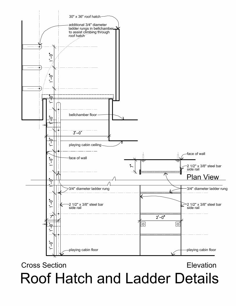
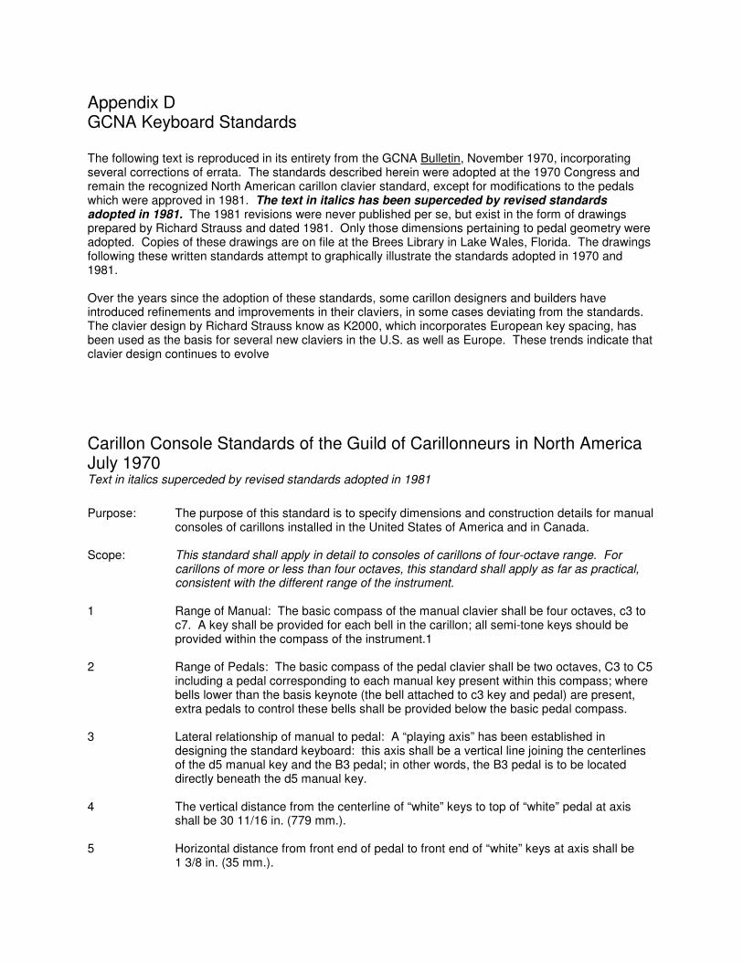
Appendix D GCNA Keyboard Standards The following text is reproduced in its entirety from the GCNA Bulletin, November 1970, incorporating several corrections of errata. The standards described herein were adopted at the 1970 Congress and remain the recognized North American carillon clavier standard, except for modifications to the pedals which were approved in 1981. The text in italics has been superceded by revised standards adopted in 1981. The 1981 revisions were never published per se, but exist in the form of drawings prepared by Richard Strauss and dated 1981. Only those dimensions pertaining to pedal geometry were adopted. Copies of these drawings are on file at the Brees Library in Lake Wales, Florida. The drawings following these written standards attempt to graphically illustrate the standards adopted in 1970 and 1981. Over the years since the adoption of these standards, some carillon designers and builders have introduced refinements and improvements in their claviers, in some cases deviating from the standards. The clavier design by Richard Strauss know as K2000, which incorporates European key spacing, has been used as the basis for several new claviers in the U.S. as well as Europe. These trends indicate that clavier design continues to evolve Carillon Console Standards of the Guild of Carillonneurs in North America July 1970 Text in italics superceded by revised standards adopted in 1981 Purpose: The purpose of this standard is to specify dimensions and construction details for manual
consoles of carillons installed in the United States of America and in Canada. Scope: This standard shall apply in detail to consoles of carillons of four-octave range. For
carillons of more or less than four octaves, this standard shall apply as far as practical, consistent with the different range of the instrument.
1 Range of Manual: The basic compass of the manual clavier shall be four octaves, c3 to
c7. A key shall be provided for each bell in the carillon; all semi-tone keys should be provided within the compass of the instrument.1
2 Range of Pedals: The basic compass of the pedal clavier shall be two octaves, C3 to C5
including a pedal corresponding to each manual key present within this compass; where bells lower than the basis keynote (the bell attached to c3 key and pedal) are present, extra pedals to control these bells shall be provided below the basic pedal compass.
3 Lateral relationship of manual to pedal: A “playing axis” has been established in
designing the standard keyboard: this axis shall be a vertical line joining the centerlines of the d5 manual key and the B3 pedal; in other words, the B3 pedal is to be located directly beneath the d5 manual key.
4 The vertical distance from the centerline of “white” keys to top of “white” pedal at axis
shall be 30 11/16 in. (779 mm.). 5 Horizontal distance from front end of pedal to front end of “white” keys at axis shall be
1 3/8 in. (35 mm.).
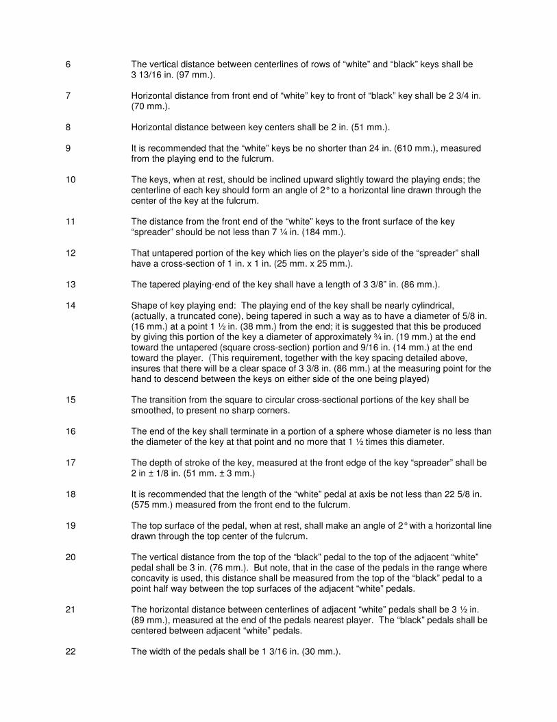
6 The vertical distance between centerlines of rows of “white” and “black” keys shall be 3 13/16 in. (97 mm.).
7 Horizontal distance from front end of “white” key to front of “black” key shall be 2 3/4 in.
(70 mm.). 8 Horizontal distance between key centers shall be 2 in. (51 mm.). 9 It is recommended that the “white” keys be no shorter than 24 in. (610 mm.), measured
from the playing end to the fulcrum. 10 The keys, when at rest, should be inclined upward slightly toward the playing ends; the
centerline of each key should form an angle of 2° to a horizontal line drawn through the center of the key at the fulcrum.
11 The distance from the front end of the “white” keys to the front surface of the key
“spreader” should be not less than 7 ¼ in. (184 mm.). 12 That untapered portion of the key which lies on the player’s side of the “spreader” shall
have a cross-section of 1 in. x 1 in. (25 mm. x 25 mm.). 13 The tapered playing-end of the key shall have a length of 3 3/8” in. (86 mm.). 14 Shape of key playing end: The playing end of the key shall be nearly cylindrical,
(actually, a truncated cone), being tapered in such a way as to have a diameter of 5/8 in. (16 mm.) at a point 1 ½ in. (38 mm.) from the end; it is suggested that this be produced by giving this portion of the key a diameter of approximately ¾ in. (19 mm.) at the end toward the untapered (square cross-section) portion and 9/16 in. (14 mm.) at the end toward the player. (This requirement, together with the key spacing detailed above, insures that there will be a clear space of 3 3/8 in. (86 mm.) at the measuring point for the hand to descend between the keys on either side of the one being played)
15 The transition from the square to circular cross-sectional portions of the key shall be
smoothed, to present no sharp corners. 16 The end of the key shall terminate in a portion of a sphere whose diameter is no less than
the diameter of the key at that point and no more that 1 ½ times this diameter. 17 The depth of stroke of the key, measured at the front edge of the key “spreader” shall be
2 in ± 1/8 in. (51 mm. ± 3 mm.) 18 It is recommended that the length of the “white” pedal at axis be not less than 22 5/8 in.
(575 mm.) measured from the front end to the fulcrum. 19 The top surface of the pedal, when at rest, shall make an angle of 2° with a horizontal line
drawn through the top center of the fulcrum. 20 The vertical distance from the top of the “black” pedal to the top of the adjacent “white”
pedal shall be 3 in. (76 mm.). But note, that in the case of the pedals in the range where concavity is used, this distance shall be measured from the top of the “black” pedal to a point half way between the top surfaces of the adjacent “white” pedals.
21 The horizontal distance between centerlines of adjacent “white” pedals shall be 3 ½ in.
(89 mm.), measured at the end of the pedals nearest player. The “black” pedals shall be centered between adjacent “white” pedals.
22 The width of the pedals shall be 1 3/16 in. (30 mm.).
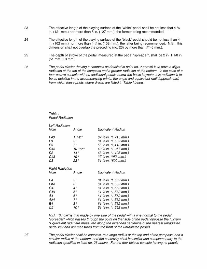
23 The effective length of the playing surface of the “white” pedal shall be not less that 4 ¾
in. (121 mm.) nor more than 5 in. (127 mm.), the former being recommended. 24 The effective length of the playing surface of the “black” pedal should be not less than 4
in. (102 mm.) nor more than 4 ¼ in. (108 mm.), the latter being recommended. N.B.: this dimension shall not overlap the preceding (no. 23) by more than ¼” (6 mm.).
25 The depth of stroke of the pedal, measured at the pedal “spreader”, shall be 2 in. ± 1/8 in.
(51 mm. ± 3 mm.). 26 The pedal clavier (having a compass as detailed in point no. 2 above) is to have a slight
radiation at the top of the compass and a greater radiation at the bottom. In the case of a four-octave console with no additional pedals below the basic keynote, this radiation is to be as detailed in the accompanying prints; the angle and equivalent radii (approximate) from which these prints where drawn are listed in Table I below:
Table I Pedal Radiation Left Radiation Note Angle Equivalent Radius F#3 1 1/2° 67 ½ in. (1,715 mm.) F3 2° 61 ½ in. (1,562 mm.) E3 7° 55 ½ in. (1,410 mm.) D#3 10 1/2° 49 ½ in. (1,257 mm.) D3 14° 43 ½ in. (1,105 mm.) C#3 19° 37 ½ in. (953 mm.) C3 23° 31 ½ in. (800 mm.) Right Radiation Note Angle Equivalent Radius F4 2° 61 ½ in. (1,562 mm.) F#4 3° 61 ½ in. (1,562 mm.) G4 4° 61 ½ in. (1,562 mm.) G#4 5° 61 ½ in. (1,562 mm.) A4 6° 61 ½ in. (1,562 mm.) A#4 7° 61 ½ in. (1,562 mm.) B4 8° 61 ½ in. (1,562 mm.) C5 10° 61 ½ in. (1,562 mm.) N.B.: “Angle” is that made by one side of the pedal with a line normal to the pedal
“spreader” which passes through the point on that side of the pedal opposite the fulcrum. “Equivalent radii” are measured along the extended centerline of the nearest unradiated pedal key and are measured from the front of the unradiated pedals.
27 The pedal clavier shall be concave, to a large radius at the top end of the compass, and a
smaller radius at the bottom, and the concavity shall be similar and complementary to the radiation specified in item no. 26 above. For the four-octave console having no pedals
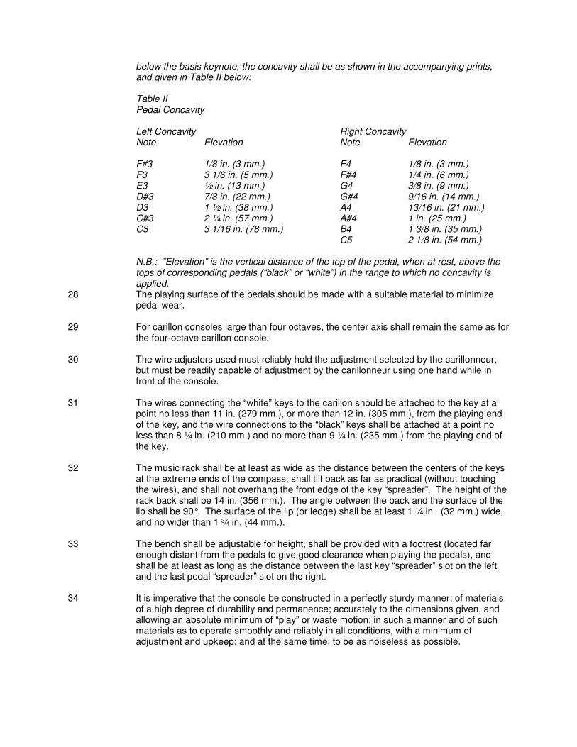
below the basis keynote, the concavity shall be as shown in the accompanying prints, and given in Table II below:
Table II Pedal Concavity Left Concavity Right Concavity Note Elevation Note Elevation F#3 1/8 in. (3 mm.) F4 1/8 in. (3 mm.) F3 3 1/6 in. (5 mm.) F#4 1/4 in. (6 mm.) E3 ½ in. (13 mm.) G4 3/8 in. (9 mm.) D#3 7/8 in. (22 mm.) G#4 9/16 in. (14 mm.) D3 1 ½ in. (38 mm.) A4 13/16 in. (21 mm.) C#3 2 ¼ in. (57 mm.) A#4 1 in. (25 mm.) C3 3 1/16 in. (78 mm.) B4 1 3/8 in. (35 mm.) C5 2 1/8 in. (54 mm.) N.B.: “Elevation” is the vertical distance of the top of the pedal, when at rest, above the
tops of corresponding pedals (“black” or “white”) in the range to which no concavity is applied.
28 The playing surface of the pedals should be made with a suitable material to minimize pedal wear.
29 For carillon consoles large than four octaves, the center axis shall remain the same as for
the four-octave carillon console. 30 The wire adjusters used must reliably hold the adjustment selected by the carillonneur,
but must be readily capable of adjustment by the carillonneur using one hand while in front of the console.
31 The wires connecting the “white” keys to the carillon should be attached to the key at a
point no less than 11 in. (279 mm.), or more than 12 in. (305 mm.), from the playing end of the key, and the wire connections to the “black” keys shall be attached at a point no less than 8 ¼ in. (210 mm.) and no more than 9 ¼ in. (235 mm.) from the playing end of the key.
32 The music rack shall be at least as wide as the distance between the centers of the keys
at the extreme ends of the compass, shall tilt back as far as practical (without touching the wires), and shall not overhang the front edge of the key “spreader”. The height of the rack back shall be 14 in. (356 mm.). The angle between the back and the surface of the lip shall be 90°. The surface of the lip (or ledge) shall be at least 1 ¼ in. (32 mm.) wide, and no wider than 1 ¾ in. (44 mm.).
33 The bench shall be adjustable for height, shall be provided with a footrest (located far
enough distant from the pedals to give good clearance when playing the pedals), and shall be at least as long as the distance between the last key “spreader” slot on the left and the last pedal “spreader” slot on the right.
34 It is imperative that the console be constructed in a perfectly sturdy manner; of materials
of a high degree of durability and permanence; accurately to the dimensions given, and allowing an absolute minimum of “play” or waste motion; in such a manner and of such materials as to operate smoothly and reliably in all conditions, with a minimum of adjustment and upkeep; and at the same time, to be as noiseless as possible.