CARF Gee Bee R2 replica · The Replica After nearly 60 years of mystique and infamy, two stunt...
36
Instruction Manual History In 1932 the Granville Brothers began construction on two nearly identical race planes, the Gee Bee’s R1 and R2. The R1, with its 800 HP Pratt and Whitney Wasp radial, was built for all- out speed with one goal in mind, to win the Thompson Trophy. The R2 was fitted with a smaller 535 HP Wasp Jr. and twice the R1’s fuel capacity for competition in the long distance Bendix Trophy speed dash. The ‘R’ Gee Bees were actually designed by young engineer, Howell “Pete” Miller who (with little more than a slide rule) calculated the R1’s top speed to be 298 mph. The Granvilles achieved victory at the 1932 Thompson with Jimmy Doolittle setting a new world landplane speed record, piloting the R1 to 296 mph. An oil leak caused unexpected delays for pilot Lee Gehlbach, resulting in a 4 th place finish for the R2 in the Bendix. It was immediately clear that the Granville’s Gee Bee racers were the ‘yardstick’ by which all other race planes (and military pursuit planes) were to be measured during those golden years of 1930’s air racing. Despite their innovative, cutting edge designs, the Gee Bee racers soon developed a notorious reputation, mostly due to bad luck and pilot error. Indeed, the Models Z, R1 and R2 placed extremely high demands on their pilots, many of whom made up for a lack of skill with sheer determination and courage. However, even this wasn’t enough to overcome some of the Gee Bee’s nasty habits and multiple accidents finally forced the Granvilles to close up shop.
Transcript of CARF Gee Bee R2 replica · The Replica After nearly 60 years of mystique and infamy, two stunt...

Instruction Manual
History In 1932 the Granville Brothers began construction on two nearly identical race planes, the
Gee Bee’s R1 and R2. The R1, with its 800 HP Pratt and Whitney Wasp radial, was built for all-out speed with one goal in mind, to win the Thompson Trophy. The R2 was fitted with a smaller 535 HP Wasp Jr. and twice the R1’s fuel capacity for competition in the long distance Bendix Trophy speed dash. The ‘R’ Gee Bees were actually designed by young engineer, Howell “Pete” Miller who (with little more than a slide rule) calculated the R1’s top speed to be 298 mph.
The Granvilles achieved victory at the 1932 Thompson with Jimmy Doolittle setting a new world landplane speed record, piloting the R1 to 296 mph. An oil leak caused unexpected delays for pilot Lee Gehlbach, resulting in a 4th place finish for the R2 in the Bendix. It was immediately clear that the Granville’s Gee Bee racers were the ‘yardstick’ by which all other race planes (and military pursuit planes) were to be measured during those golden years of 1930’s air racing.
Despite their innovative, cutting edge designs, the Gee Bee racers soon developed a notorious reputation, mostly due to bad luck and pilot error. Indeed, the Models Z, R1 and R2 placed extremely high demands on their pilots, many of whom made up for a lack of skill with sheer determination and courage. However, even this wasn’t enough to overcome some of the Gee Bee’s nasty habits and multiple accidents finally forced the Granvilles to close up shop.
2
“Although these airplanes were noble experiments, Jimmy and I both considered they were too hot for anybody to handle. We believed that we had used up a considerable portion of our earthly share of luck. We never even sat in them again. We really didn’t consider ourselves any more skillful than the boys who later crashed these jobs. Our guardian angels had just stood by us in our hour of need.” - Lee Gehlbach, Air Trails, 1939
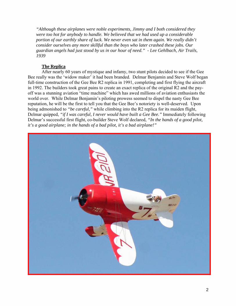
The Replica After nearly 60 years of mystique and infamy, two stunt pilots decided to see if the Gee
Bee really was the ‘widow maker’ it had been branded. Delmar Benjamin and Steve Wolf began full-time construction of the Gee Bee R2 replica in 1991, completing and first flying the aircraft in 1992. The builders took great pains to create an exact replica of the original R2 and the pay-off was a stunning aviation “time machine” which has awed millions of aviation enthusiasts the world over. While Delmar Benjamin’s piloting prowess seemed to dispel the nasty Gee Bee reputation, he will be the first to tell you that the Gee Bee’s notoriety is well-deserved. Upon being admonished to “be careful,” while climbing into the R2 replica for its maiden flight, Delmar quipped, “if I was careful, I never would have built a Gee Bee.” Immediately following Delmar’s successful first flight, co-builder Steve Wolf declared, “In the hands of a good pilot, it’s a good airplane; in the hands of a bad pilot, it’s a bad airplane!”

3
Liability Exclusion and Damages You have acquired a kit, which can be assembled into a fully working R/C model when
fitted out with suitable accessories, as described in the instruction manual with the kit. However, as manufacturers, we at CARF Models are not in a position to influence the way you build and operate your model, and we have no control over the methods you use to install, operate and maintain the radio control system components. For this reason we are obliged to deny all liability for loss, damage or costs which are incurred due to the incompetent or incorrect application and operation of our products, or which are connected with such operation in any way. Unless otherwise prescribed by binding law, the obligation of the CARF Models company to pay compensation is excluded, regardless of the legal argument employed. This applies to personal injury, death, damage to buildings, loss of turnover and business, interruption of business or other direct and indirect consequent damages. In all circumstances our total liability is limited to the amount which you actually paid for this model. BY OPERATING THIS MODEL YOU ASSUME FULL RESPONSIBILITY FOR YOUR ACTIONS.
It is important to understand that CARF-Models Ltd, is unable to monitor whether you follow the instructions contained in this instruction manual regarding the construction, operation and maintenance of the aircraft, nor whether you install and use the radio control system correctly. For this reason we at CARF Models are unable to guarantee or provide a contractual agreement with any individual or company that the model you have made will function correctly and safely. You, as operator of the model, must rely upon your own expertise and judgment in acquiring and operating this model.
General information about fully-composite aircraft structure and design
All the parts are produced in negative molds, manufactured using vacuum-bagged sandwich construction technology. All parts are painted in the molds, either single color or designer color schemes.
The kit utilizes materials and building techniques that may not be familiar to conventional ARF and (wood) RC model builders and while the aircraft is not extremely difficult to construct, it should not be undertaken by an inexperienced builder or flyer. You should be intimately familiar with giant scale aircraft and the higher demands placed on structures due to greater flying weights, high-powered gasoline engines, and the associated heavy duty radio equipment and hardware required.
Take Care: Composite sandwich parts are extremely strong, but fragile at the same time. Keep in mind that these high-performance airplanes are designed for minimum weight and maximum strength in flight. Please take care, especially during transport, to make sure that none of the critical parts and linkages are damaged. Always handle your airplane with great care and it will provide you with many hours of pride and pleasure. Before you get started building and setting-up your aircraft, please make sure you have read this instruction manual several times, and understood it. If you have any questions, please don’t hesitate to contact us. Below are the contact details:
4
Email: [email protected] Website: http://www.carf-models.com
The Model CARF Models has taken great care to create a 31% sized ARF replica of the
Benjamin/Wolf R2 so that you can also successfully build and fly one. Unlike many other Gee Bee kits which have come and gone, the CompARF R2 is as close to the original in outline and plan-form as possible, including airfoil, empennage, and right rudder molded into the vertical fin. Why mess with success?!
Landing Gear and Engine Selection The CARF Gee Bee R2 is designed for the custom oleo landing gear (Product # 410009)
offered for sale as an accessory by CARF Models and it is assumed the builder has acquired the main gear and all other recommended accessories and building materials before proceeding. Familiarity with various epoxies and CA glue are integral to the construction of the aircraft and a list of required construction materials and hardware follows this introduction.
The CompARF Gee Bee was originally designed to fly with a 3W 120cc opposed twin. It has also been successfully flown with various radial engines ranging from 125cc to 250cc. The highest performance at the lightest weight will be attained with a modern gasoline twin ranging from 100cc to 150cc. 3W, Desert Aircraft, Evolution, Quadra-Aerrow, and other manufacturers offer modern, reliable and powerful gasoline twins in the appropriate sizes and some of these engines have earned a stellar reputation in IMAC and 3D competition. While prop spinning ability is an important consideration in your choice of power plant, RELIABILITY is tantamount to your Gee Bee’s survival and success. Like the full scale version, the CARF Gee Bee is not known for its gliding ability and a dead engine at the wrong time (is there ever a right time?) will usually ruin your day, not to mention your Gee Bee. Keep this in mind when you choose and set up your power plant. While engines as small as 80cc might successfully fly the Gee Bee, an underpowered Gee Bee will present additional pilot demands, creating unnecessary risks. An extremely light engine will also present significant challenges in achieving the proper final balance (Center of Gravity). If you do not possess the appropriate power plant, put your Gee Bee kit on the shelf and save your money until you have acquired one.
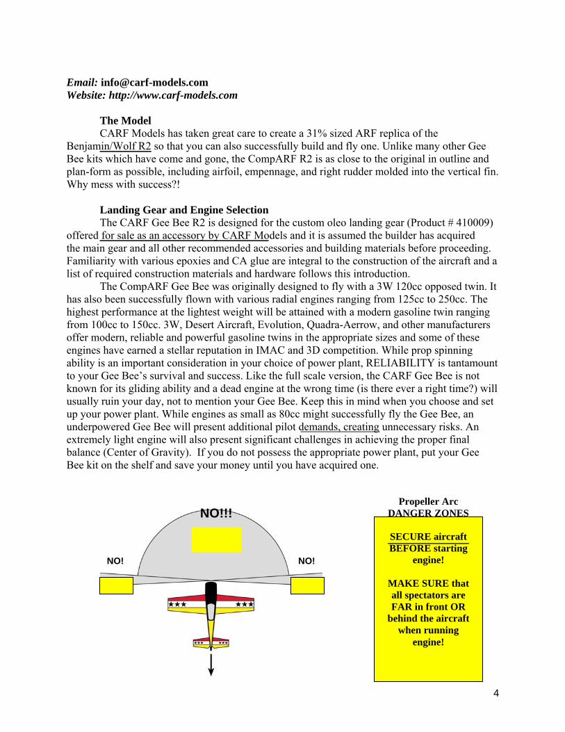
NO!!!
NO! NO!
Propeller Arc DANGER ZONES
SECURE aircraft BEFORE starting
engine!
MAKE SURE that all spectators are FAR in front OR
behind the aircraft when running
engine!

5
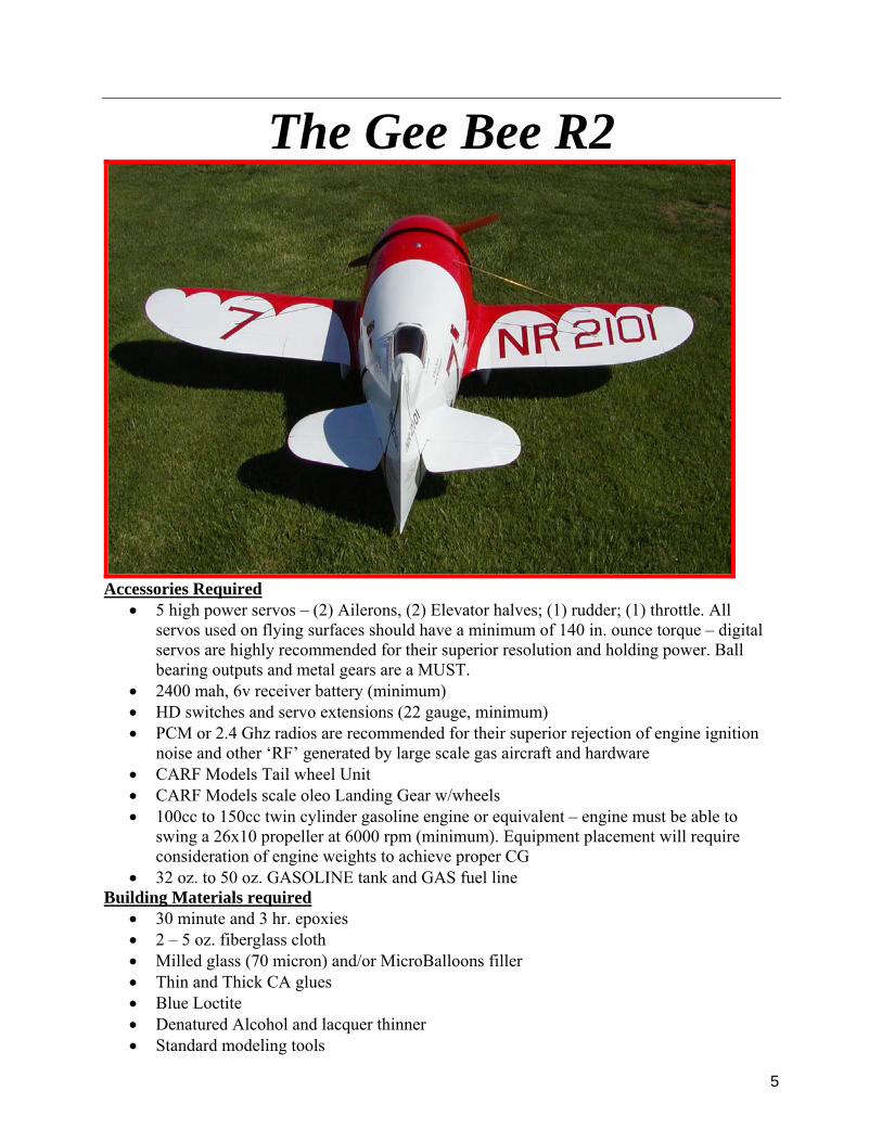
The Gee Bee R2
Accessories Required
• 5 high power servos – (2) Ailerons, (2) Elevator halves; (1) rudder; (1) throttle. All servos used on flying surfaces should have a minimum of 140 in. ounce torque – digital servos are highly recommended for their superior resolution and holding power. Ball bearing outputs and metal gears are a MUST.
• 2400 mah, 6v receiver battery (minimum) • HD switches and servo extensions (22 gauge, minimum) • PCM or 2.4 Ghz radios are recommended for their superior rejection of engine ignition
noise and other ‘RF’ generated by large scale gas aircraft and hardware • CARF Models Tail wheel Unit • CARF Models scale oleo Landing Gear w/wheels • 100cc to 150cc twin cylinder gasoline engine or equivalent – engine must be able to
swing a 26x10 propeller at 6000 rpm (minimum). Equipment placement will require consideration of engine weights to achieve proper CG
• 32 oz. to 50 oz. GASOLINE tank and GAS fuel line Building Materials required
• 30 minute and 3 hr. epoxies • 2 – 5 oz. fiberglass cloth • Milled glass (70 micron) and/or MicroBalloons filler • Thin and Thick CA glues • Blue Loctite • Denatured Alcohol and lacquer thinner • Standard modeling tools
6
Decals and Markings • Kirby’s Kustom Vinyl Graphics offers a complete set of scale markings to replicate the
Benjamin Gee Bee R2 • 2mm black or dark blue striping tape (for scallop outlines) • Red and white touch up paints and hardener can be acquired directly from CARF - P/Ns
970008 (red); 970002 (white); 970012 (hardener) Let us Begin – We highly recommend that you inventory your kit, followed by the application of two coats of automotive wax to all aircraft surfaces. Do not remove the wax. Allow it to remain on the model and re-apply it as it rubs off. The wax will help protect your model from workbench mishaps, allowing easier removal of epoxy or other substances or even small scratches as you progress through construction. Note: ALWAYS lightly sand then thoroughly clean (with lacquer thinner or alcohol) composite surfaces that are to be glued. This will create a superior bond. Gather all recommended building materials, radio gear, engine and any anticipated extra hardware as this will greatly speed the assembly process.
READ THIS MANUAL FROM COVER TO COVER BEFORE YOU DO ANYTHING!
ALWAYS, ALWAYS, ALWAYS READ AHEAD! DO NOT ASSUME THE PAGE YOU ARE FOLLOWING CONTAINS ALL PERTINENT ASSEMBLY INFORMATION.
Landing Gear Your Gee Bee will be much easier to handle once it is sitting on its wheels so let’s start by mounting the gear. Before you begin, it is advisable that you partially disassemble the gear and apply grease at all pivot points as well as on the oleo inner and outer sleeves. This will allow the gear to function more smoothly. Also, you must retain the lower fork of the gear or risk having it separate from the upper gear, once airborne. Tie wraps function as an effective restraint. Verify that fork retention does not interfere with the action of the gear or with wheel rotation. The provided wheels may require additional narrowing to assure maximum rotational clearance. This can be accomplished by utilizing a long bolt as an ‘axle,’ then chucking up the wheel in a drill press; starting with very course sandpaper, then progressively finer paper until the sidewall and tire contour exhibit sufficient clearance.
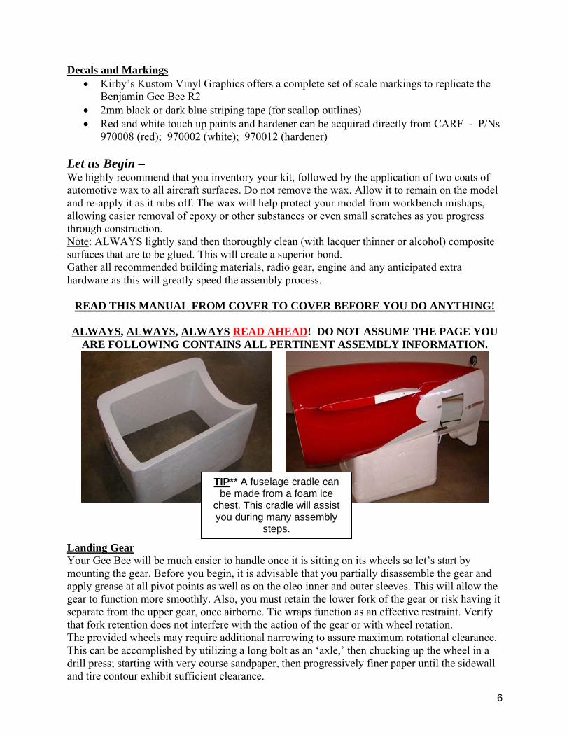
TIP** A fuselage cradle can be made from a foam ice
chest. This cradle will assist you during many assembly
steps.

7
ON LEFT – comparison of stock tire to tire with additional clearance. ON RIGHT – tire has had additional radius clearance. This will assure tires cannot rub on gear forks under any condition.
Arrows point to areas that require lubrication. Hubs should be well packed with grease. Tie wraps or other strapping must be utilized to retain lower fork.
8
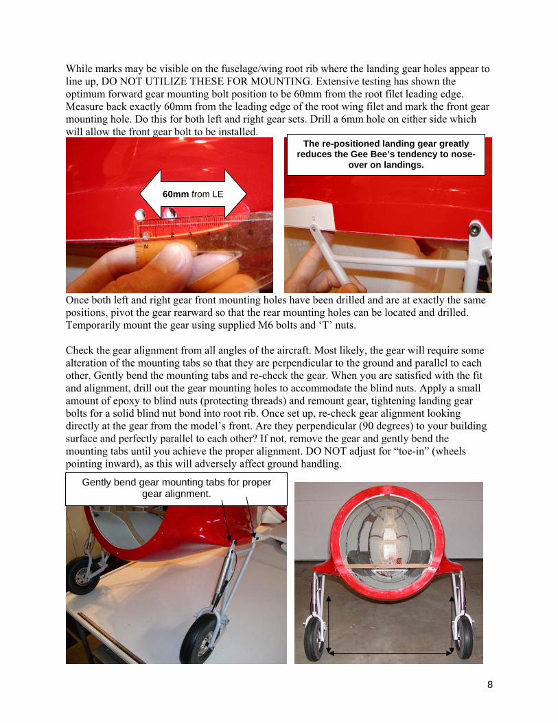
While marks may be visible on the fuselage/wing root rib where the landing gear holes appear to line up, DO NOT UTILIZE THESE FOR MOUNTING. Extensive testing has shown the optimum forward gear mounting bolt position to be 60mm from the root filet leading edge. Measure back exactly 60mm from the leading edge of the root wing filet and mark the front gear mounting hole. Do this for both left and right gear sets. Drill a 6mm hole on either side which will allow the front gear bolt to be installed.
Once both left and right gear front mounting holes have been drilled and are at exactly the same positions, pivot the gear rearward so that the rear mounting holes can be located and drilled. Temporarily mount the gear using supplied M6 bolts and ‘T’ nuts. Check the gear alignment from all angles of the aircraft. Most likely, the gear will require some alteration of the mounting tabs so that they are perpendicular to the ground and parallel to each other. Gently bend the mounting tabs and re-check the gear. When you are satisfied with the fit and alignment, drill out the gear mounting holes to accommodate the blind nuts. Apply a small amount of epoxy to blind nuts (protecting threads) and remount gear, tightening landing gear bolts for a solid blind nut bond into root rib. Once set up, re-check gear alignment looking directly at the gear from the model’s front. Are they perpendicular (90 degrees) to your building surface and perfectly parallel to each other? If not, remove the gear and gently bend the mounting tabs until you achieve the proper alignment. DO NOT adjust for “toe-in” (wheels pointing inward), as this will adversely affect ground handling.
60mm from LE
Gently bend gear mounting tabs for proper gear alignment.
The re-positioned landing gear greatly reduces the Gee Bee’s tendency to nose-
over on landings.
9
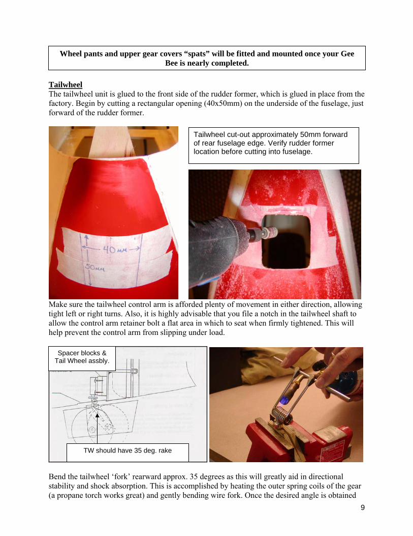
Tailwheel The tailwheel unit is glued to the front side of the rudder former, which is glued in place from the factory. Begin by cutting a rectangular opening (40x50mm) on the underside of the fuselage, just forward of the rudder former.
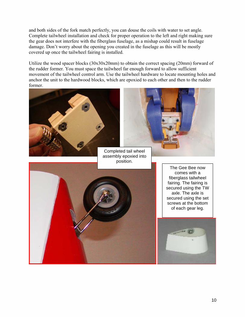
Make sure the tailwheel control arm is afforded plenty of movement in either direction, allowing tight left or right turns. Also, it is highly advisable that you file a notch in the tailwheel shaft to allow the control arm retainer bolt a flat area in which to seat when firmly tightened. This will help prevent the control arm from slipping under load.
Bend the tailwheel ‘fork’ rearward approx. 35 degrees as this will greatly aid in directional stability and shock absorption. This is accomplished by heating the outer spring coils of the gear (a propane torch works great) and gently bending wire fork. Once the desired angle is obtained
Spacer blocks & Tail Wheel assbly.
TW should have 35 deg. rake
Tailwheel cut-out approximately 50mm forward of rear fuselage edge. Verify rudder former location before cutting into fuselage.
Wheel pants and upper gear covers “spats” will be fitted and mounted once your Gee Bee is nearly completed.
10
and both sides of the fork match perfectly, you can douse the coils with water to set angle. Complete tailwheel installation and check for proper operation to the left and right making sure the gear does not interfere with the fiberglass fuselage, as a mishap could result in fuselage damage. Don’t worry about the opening you created in the fuselage as this will be mostly covered up once the tailwheel fairing is installed. Utilize the wood spacer blocks (30x30x20mm) to obtain the correct spacing (20mm) forward of the rudder former. You must space the tailwheel far enough forward to allow sufficient movement of the tailwheel control arm. Use the tailwheel hardware to locate mounting holes and anchor the unit to the hardwood blocks, which are epoxied to each other and then to the rudder former.
Completed tail wheel assembly epoxied into
position. The Gee Bee now
comes with a fiberglass tailwheel
fairing. The fairing is secured using the TW
axle. The axle is secured using the set screws at the bottom
of each gear leg.
11
FLYING WIRES This section is capitalized, italicized and underlined for a reason: The GeeBee’s flying wires don’t just look great, they are the binding force that holds this vintage
racer together, while also stabilizing the landing gear! At no time during this model’s construction should greater care be taken, than on the building of the flying wires.
ATTENTION: This is the MOST IMPORTANT STEP OF YOUR GEEBEE
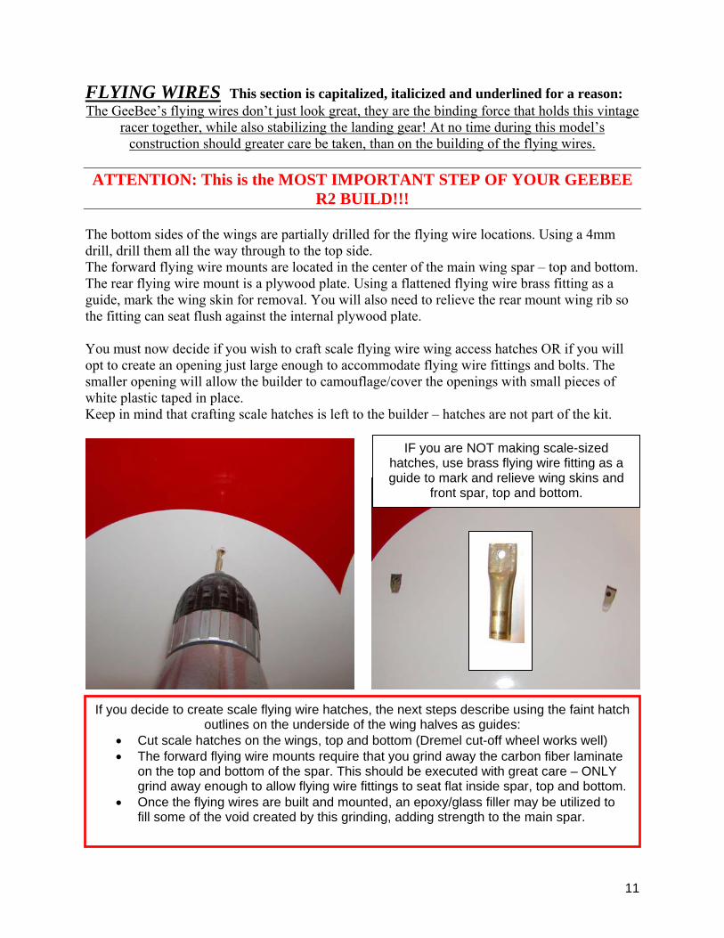
R2 BUILD!!! The bottom sides of the wings are partially drilled for the flying wire locations. Using a 4mm drill, drill them all the way through to the top side. The forward flying wire mounts are located in the center of the main wing spar – top and bottom. The rear flying wire mount is a plywood plate. Using a flattened flying wire brass fitting as a guide, mark the wing skin for removal. You will also need to relieve the rear mount wing rib so the fitting can seat flush against the internal plywood plate. You must now decide if you wish to craft scale flying wire wing access hatches OR if you will opt to create an opening just large enough to accommodate flying wire fittings and bolts. The smaller opening will allow the builder to camouflage/cover the openings with small pieces of white plastic taped in place. Keep in mind that crafting scale hatches is left to the builder – hatches are not part of the kit.
IF you are NOT making scale-sized hatches, use brass flying wire fitting as a guide to mark and relieve wing skins and
front spar, top and bottom.
If you decide to create scale flying wire hatches, the next steps describe using the faint hatch outlines on the underside of the wing halves as guides:
• Cut scale hatches on the wings, top and bottom (Dremel cut-off wheel works well) • The forward flying wire mounts require that you grind away the carbon fiber laminate
on the top and bottom of the spar. This should be executed with great care – ONLY grind away enough to allow flying wire fittings to seat flat inside spar, top and bottom.
• Once the flying wires are built and mounted, an epoxy/glass filler may be utilized to fill some of the void created by this grinding, adding strength to the main spar.

12
The flying wires will connect inside the fuselage directly to the front main fuselage former. Locate this former in relation to the ‘+’ marks on the fuselage exterior. There are two on each side indicating where the front and rear flying wires pass through the fuselage. The front ‘+’ mark should be forward of the main former. The rear ‘+’ mark should be located approx. 30mm behind the front mark. Due to production tolerances, the marks may not be located at precisely these locations, so compare the former location with the (+ +) marks BEFORE making any holes in the fuselage. A bright lamp inside fuselage will help greatly.
‘+’ marks on fuselage are used to locate flying wire exit holes. A bright light inside fuselage will help locate fuselage former for proper hole locations. Holes should be enlarged to approx. 10mm x 15mm.
Carbon fiber laminate must be ground away to allow flying wire fitting to seat inside wing – top and bottom. BE CONSERVATIVE with your grinding! Remove ONLY enough CF to allow fitting to seat AND NO MORE. This only applies to the front mounting point. The rear mount will require some grinding away of the partial rib for flying wire fitting to seat properly.
Forward bolts: M4x25mm Rear bolts: M4x20mm Nylon Lock Nuts
NOTE: Flying wire is secured below wing surface, covered by
hatch
Drill 4mm hole through wing/spar.
13
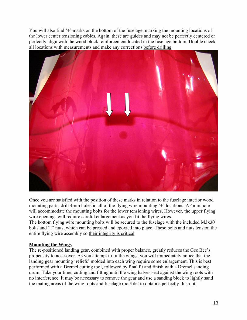
You will also find ‘+’ marks on the bottom of the fuselage, marking the mounting locations of the lower center tensioning cables. Again, these are guides and may not be perfectly centered or perfectly align with the wood block reinforcement located in the fuselage bottom. Double check all locations with measurements and make any corrections before drilling.
Once you are satisfied with the position of these marks in relation to the fuselage interior wood mounting parts, drill 4mm holes in all of the flying wire mounting ‘+’ locations. A 4mm hole will accommodate the mounting bolts for the lower tensioning wires. However, the upper flying wire openings will require careful enlargement as you fit the flying wires. The bottom flying wire mounting bolts will be secured to the fuselage with the included M3x30 bolts and ‘T’ nuts, which can be pressed and epoxied into place. These bolts and nuts tension the entire flying wire assembly so their integrity is critical. Mounting the Wings The re-positioned landing gear, combined with proper balance, greatly reduces the Gee Bee’s propensity to nose-over. As you attempt to fit the wings, you will immediately notice that the landing gear mounting ‘reliefs’ molded into each wing require some enlargement. This is best performed with a Dremel cutting tool, followed by final fit and finish with a Dremel sanding drum. Take your time, cutting and fitting until the wing halves seat against the wing roots with no interference. It may be necessary to remove the gear and use a sanding block to lightly sand the mating areas of the wing roots and fuselage root/filet to obtain a perfectly flush fit.

14
Once both wing halves fit flat against the fuselage wing root, reinstall the gear and check your gear mounting reliefs to confirm no interference.
*Flying Wire Preparation – TIP*
The wing carbon fiber dowels now come pre-installed in each wing half. Check to make sure the wing dowels align with the holes in the fuselage wing root and that each wing half slides snugly into place. Use a round file to make small adjustments in wing root for proper dowel fit.
The wing halves will be held firmly in place by the flying wires. However, it is helpful to temporarily mount the wing halves by drilling through the wing/fuselage root formers and installing wood retention screws. By doing so, you can snug the wing halves against fuselage root sections. This is MUCH easier than propping and blocking up wings in their mounted positions for measuring, cutting and mounting upper flying wires.
The included flying wire material must be accurately measured and cut to produce 8 flying wires. There is NOT ENOUGH EXTRA FOR YOU TO
MAKE MISTAKES. As the old carpenter used to say, “Measure twice, cut once!”
The following flying wire measurements can be used as a guide. Your actual lengths may vary due to manufacturing tolerances and your exact mounting hole locations. These lengths are NOT the lengths of the flying wire material alone; they are from hole center to hole center:

15
• Top Front: 750mm • Top Rear: 770mm • Bottom Front: 530mm • Bottom Rear: 560mm • Bottom Cables: 300mm
Cut the flying wire material, taking into consideration the length of the included adjustable ends AND the length of the enclosed brass tubes, which will be flattened on one end and a 4mm hole drilled through them. The adjustable flying wire end should be threaded all the way onto the
(+ +) marks on fuselage sides
locate flying wire entry/exit
3 x 30mm cable tensioning bolt and
M3 ‘T’ Nut
DO NOT shorten bolt
Fuselage Main Former
Ply or hardwood doublers epoxied to main former. Upper mounting
holes approx. 150mm apart
Lower mounting
block, factory installed
Brass tube end soldered to
Lower tensioning cable
Remember, building your flying wires must be handled as integral to the survival of your GeeBee, so take your time and do it right.
16
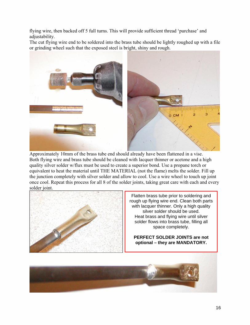
flying wire, then backed off 5 full turns. This will provide sufficient thread ‘purchase’ and adjustability. The cut flying wire end to be soldered into the brass tube should be lightly roughed up with a file or grinding wheel such that the exposed steel is bright, shiny and rough.
Approximately 10mm of the brass tube end should already have been flattened in a vise. Both flying wire and brass tube should be cleaned with lacquer thinner or acetone and a high quality silver solder w/flux must be used to create a superior bond. Use a propane torch or equivalent to heat the material until THE MATERIAL (not the flame) melts the solder. Fill up the junction completely with silver solder and allow to cool. Use a wire wheel to touch up joint once cool. Repeat this process for all 8 of the solder joints, taking great care with each and every solder joint.
Flatten brass tube prior to soldering and rough up flying wire end. Clean both parts with lacquer thinner. Only a high quality
silver solder should be used. Heat brass and flying wire until silver solder flows into brass tube, filling all
space completely.
PERFECT SOLDER JOINTS are not optional – they are MANDATORY.

17
The flattened end will be bent to match the mounting angles. The ends must seat flat against the mounting areas and must not cause the flying wire to warp or bend when bolted tight. Flying wires should be perfectly straight, mounting hole to mounting hole. Once all 8 flying wires have been completed, the included (thick) cable stock is used to create the tensioning cables that go between the inner gear mounts and the bottom fuselage mounts. These cables are used to tension the entire flying wire set up.
Tensioning Cables Start by mounting both wing halves and connecting all flying wires with the included 2mm bolts and nuts. Use the standard 2mm nuts during this process, as they are much quicker to install and remove. Once everything is set up and adjusted, the nylon-filled lock nuts will be used to mount the flying wires. Adjust upper and lower flying wires so that both wings exhibit the same dihedral while seated flush against fuselage wing root. The Landing Gear must be perpendicular to the ground and parallel to each other. Once this has been accomplished, cut two cables to length between the lower gear mounts and fuselage bottom mounting holes. The included threaded ends must be soldered to one end of each of the two cables. Thread the large aluminum clevises onto each cable and connect to inner gear attachment points with the included clevis pins (no need to install ‘C’ retainer clip at this time). Make two additional brass tube ends – flatten ends and drill 4mm mounting holes – then bolt to lower fuselage mounting block with 3mm x 30mm allen bolts. Cut both cables to length, leaving enough cable to solder into brass ends, but keeping in mind that these cables must be tightened/shortened enough to tension the entire flying wire assembly. IF they are too long, you will run out of threads before all flying wires are tight. If that happens, de-solder one end of the cable(s), cut shorter, clean and re-solder. Remove cables and solder the brass ends to tension cables. The same careful procedure used to clean and solder the flying wires should be utilized to build these cables.
Hardwood block epoxied to fuselage former provides flying wire mount spacing. Single bolt and nylon lock nut secures both.
Flying wire attachment points
shown (right)
18
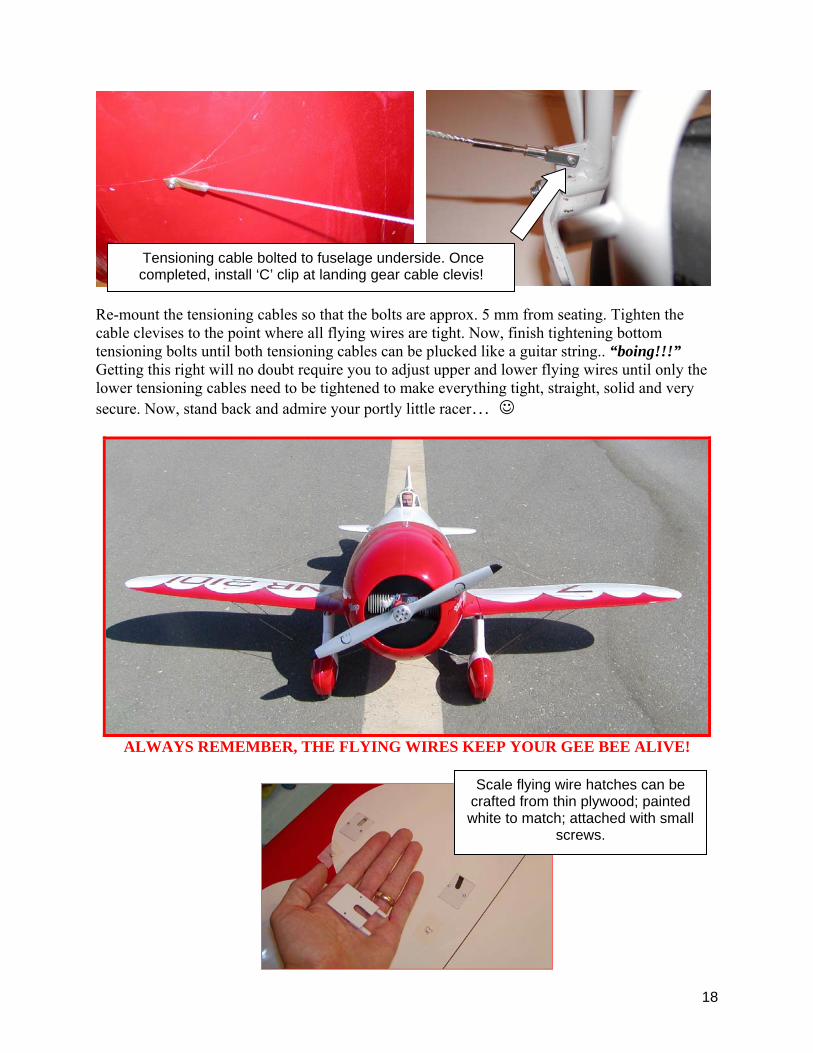
Re-mount the tensioning cables so that the bolts are approx. 5 mm from seating. Tighten the cable clevises to the point where all flying wires are tight. Now, finish tightening bottom tensioning bolts until both tensioning cables can be plucked like a guitar string.. “boing!!!” Getting this right will no doubt require you to adjust upper and lower flying wires until only the lower tensioning cables need to be tightened to make everything tight, straight, solid and very secure. Now, stand back and admire your portly little racer… ☺
ALWAYS REMEMBER, THE FLYING WIRES KEEP YOUR GEE BEE ALIVE!
Tensioning cable bolted to fuselage underside. Once completed, install ‘C’ clip at landing gear cable clevis!
Scale flying wire hatches can be crafted from thin plywood; painted white to match; attached with small
screws.
19
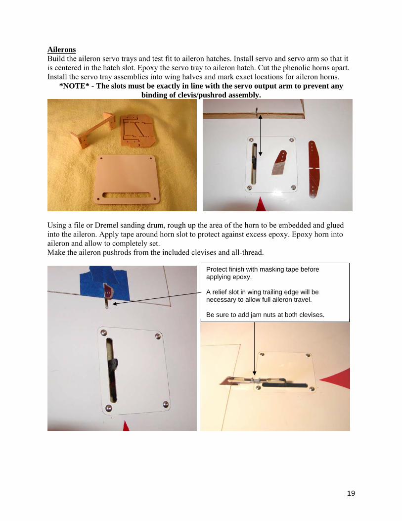
Ailerons Build the aileron servo trays and test fit to aileron hatches. Install servo and servo arm so that it is centered in the hatch slot. Epoxy the servo tray to aileron hatch. Cut the phenolic horns apart. Install the servo tray assemblies into wing halves and mark exact locations for aileron horns.
*NOTE* - The slots must be exactly in line with the servo output arm to prevent any binding of clevis/pushrod assembly.
Using a file or Dremel sanding drum, rough up the area of the horn to be embedded and glued into the aileron. Apply tape around horn slot to protect against excess epoxy. Epoxy horn into aileron and allow to completely set. Make the aileron pushrods from the included clevises and all-thread.
Protect finish with masking tape before applying epoxy. A relief slot in wing trailing edge will be necessary to allow full aileron travel. Be sure to add jam nuts at both clevises.
20
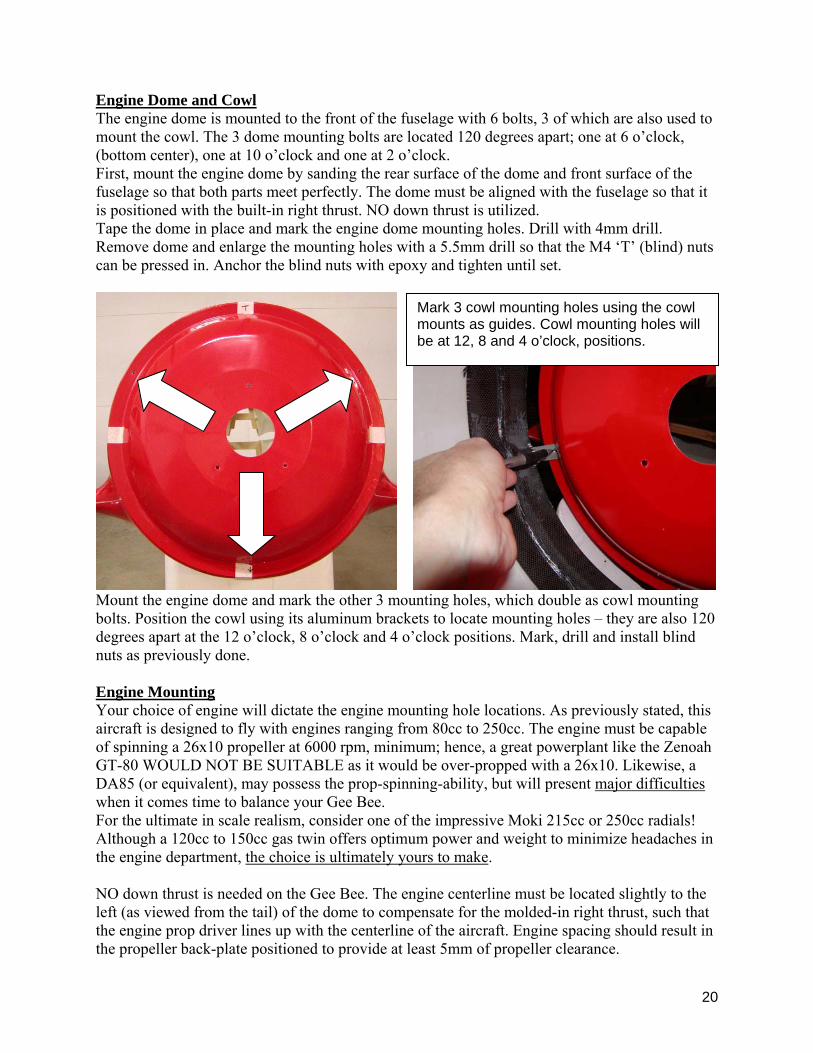
Engine Dome and Cowl The engine dome is mounted to the front of the fuselage with 6 bolts, 3 of which are also used to mount the cowl. The 3 dome mounting bolts are located 120 degrees apart; one at 6 o’clock, (bottom center), one at 10 o’clock and one at 2 o’clock. First, mount the engine dome by sanding the rear surface of the dome and front surface of the fuselage so that both parts meet perfectly. The dome must be aligned with the fuselage so that it is positioned with the built-in right thrust. NO down thrust is utilized. Tape the dome in place and mark the engine dome mounting holes. Drill with 4mm drill. Remove dome and enlarge the mounting holes with a 5.5mm drill so that the M4 ‘T’ (blind) nuts can be pressed in. Anchor the blind nuts with epoxy and tighten until set.
Mount the engine dome and mark the other 3 mounting holes, which double as cowl mounting bolts. Position the cowl using its aluminum brackets to locate mounting holes – they are also 120 degrees apart at the 12 o’clock, 8 o’clock and 4 o’clock positions. Mark, drill and install blind nuts as previously done. Engine Mounting Your choice of engine will dictate the engine mounting hole locations. As previously stated, this aircraft is designed to fly with engines ranging from 80cc to 250cc. The engine must be capable of spinning a 26x10 propeller at 6000 rpm, minimum; hence, a great powerplant like the Zenoah GT-80 WOULD NOT BE SUITABLE as it would be over-propped with a 26x10. Likewise, a DA85 (or equivalent), may possess the prop-spinning-ability, but will present major difficulties when it comes time to balance your Gee Bee. For the ultimate in scale realism, consider one of the impressive Moki 215cc or 250cc radials! Although a 120cc to 150cc gas twin offers optimum power and weight to minimize headaches in the engine department, the choice is ultimately yours to make. NO down thrust is needed on the Gee Bee. The engine centerline must be located slightly to the left (as viewed from the tail) of the dome to compensate for the molded-in right thrust, such that the engine prop driver lines up with the centerline of the aircraft. Engine spacing should result in the propeller back-plate positioned to provide at least 5mm of propeller clearance.
Mark 3 cowl mounting holes using the cowl mounts as guides. Cowl mounting holes will be at 12, 8 and 4 o’clock, positions.
21
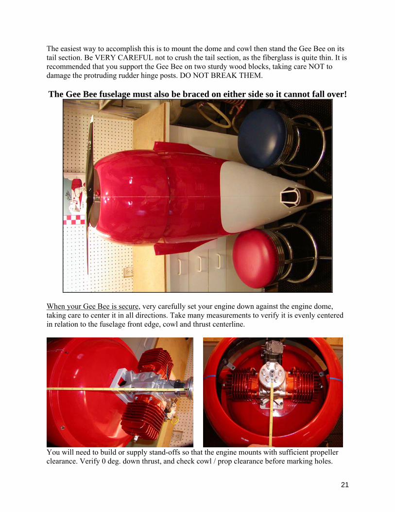
The easiest way to accomplish this is to mount the dome and cowl then stand the Gee Bee on its tail section. Be VERY CAREFUL not to crush the tail section, as the fiberglass is quite thin. It is recommended that you support the Gee Bee on two sturdy wood blocks, taking care NOT to damage the protruding rudder hinge posts. DO NOT BREAK THEM. The Gee Bee fuselage must also be braced on either side so it cannot fall over!
When your Gee Bee is secure, very carefully set your engine down against the engine dome, taking care to center it in all directions. Take many measurements to verify it is evenly centered in relation to the fuselage front edge, cowl and thrust centerline.
You will need to build or supply stand-offs so that the engine mounts with sufficient propeller clearance. Verify 0 deg. down thrust, and check cowl / prop clearance before marking holes.
22
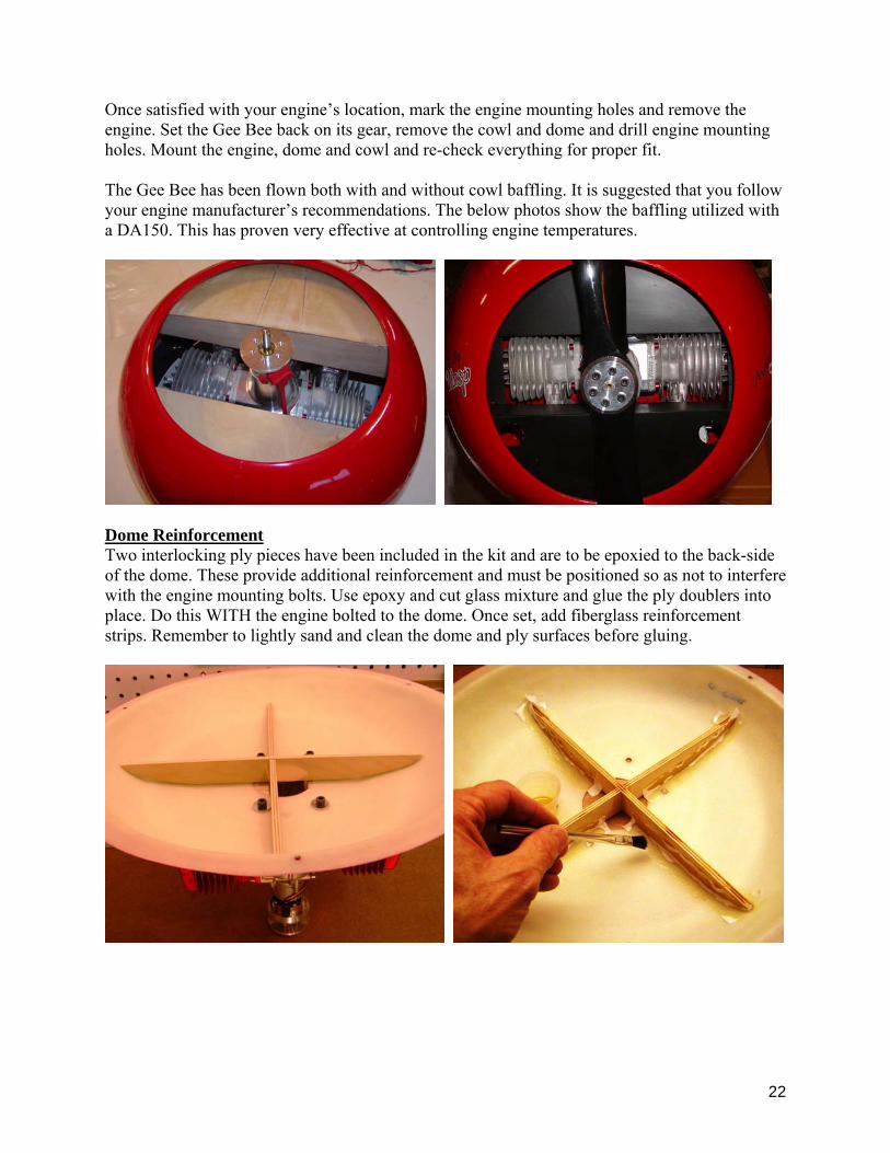
Once satisfied with your engine’s location, mark the engine mounting holes and remove the engine. Set the Gee Bee back on its gear, remove the cowl and dome and drill engine mounting holes. Mount the engine, dome and cowl and re-check everything for proper fit. The Gee Bee has been flown both with and without cowl baffling. It is suggested that you follow your engine manufacturer’s recommendations. The below photos show the baffling utilized with a DA150. This has proven very effective at controlling engine temperatures.
Dome Reinforcement Two interlocking ply pieces have been included in the kit and are to be epoxied to the back-side of the dome. These provide additional reinforcement and must be positioned so as not to interfere with the engine mounting bolts. Use epoxy and cut glass mixture and glue the ply doublers into place. Do this WITH the engine bolted to the dome. Once set, add fiberglass reinforcement strips. Remember to lightly sand and clean the dome and ply surfaces before gluing.
23
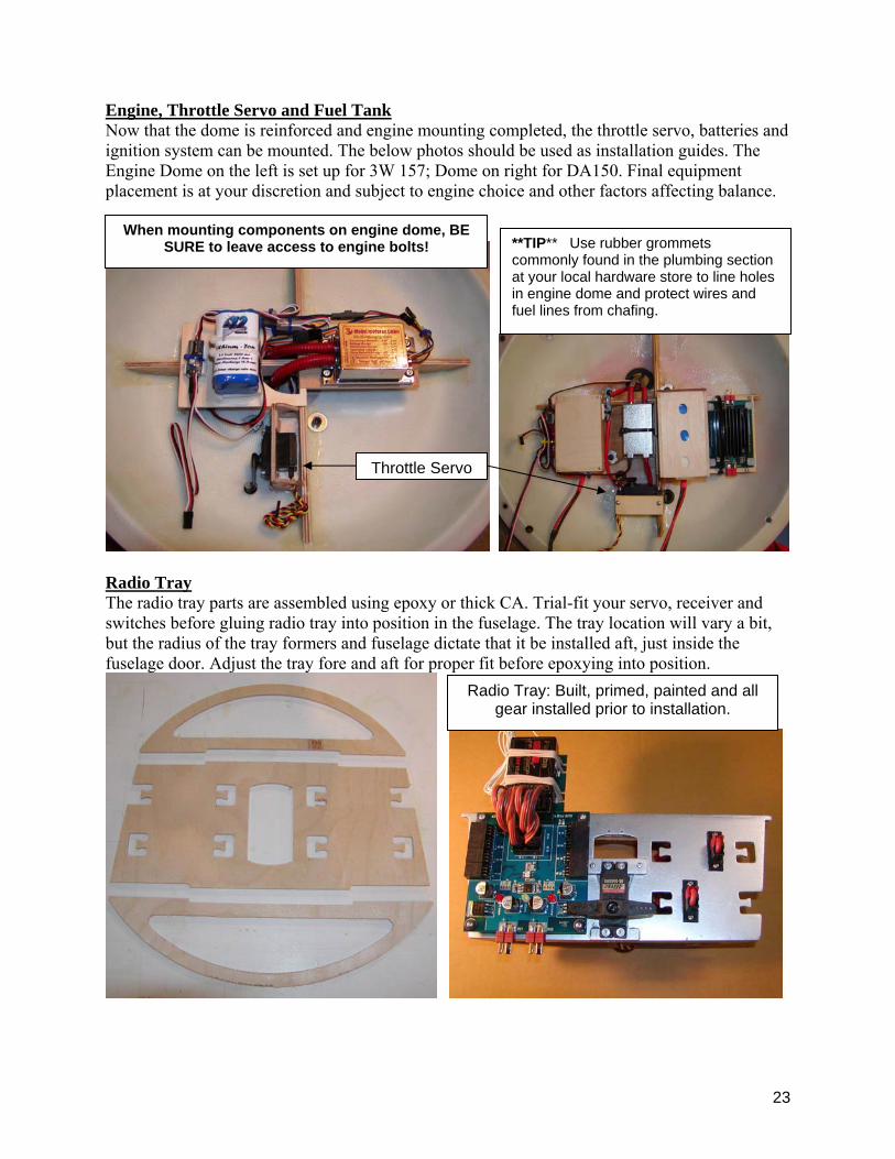
Engine, Throttle Servo and Fuel Tank Now that the dome is reinforced and engine mounting completed, the throttle servo, batteries and ignition system can be mounted. The below photos should be used as installation guides. The Engine Dome on the left is set up for 3W 157; Dome on right for DA150. Final equipment placement is at your discretion and subject to engine choice and other factors affecting balance.
Radio Tray The radio tray parts are assembled using epoxy or thick CA. Trial-fit your servo, receiver and switches before gluing radio tray into position in the fuselage. The tray location will vary a bit, but the radius of the tray formers and fuselage dictate that it be installed aft, just inside the fuselage door. Adjust the tray fore and aft for proper fit before epoxying into position.
**TIP** Use rubber grommets commonly found in the plumbing section at your local hardware store to line holes in engine dome and protect wires and fuel lines from chafing.
Radio Tray: Built, primed, painted and all gear installed prior to installation.
Throttle Servo
When mounting components on engine dome, BE SURE to leave access to engine bolts!
24
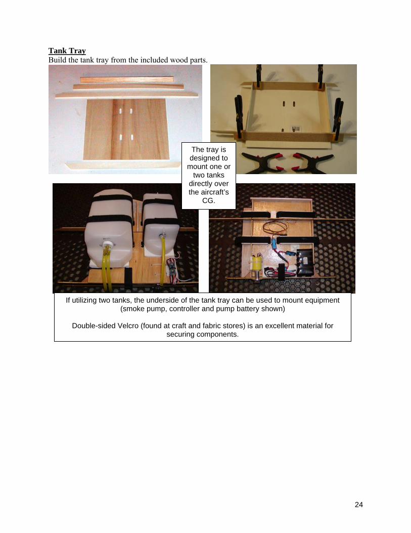
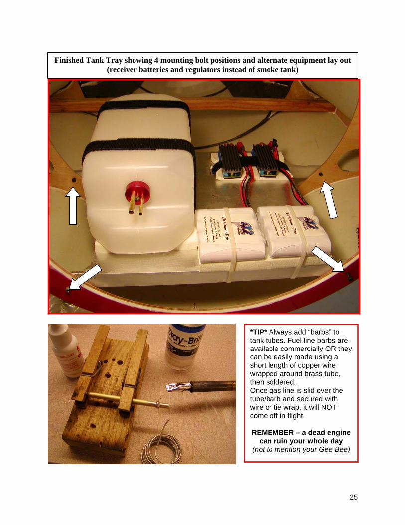
Tank Tray Build the tank tray from the included wood parts.
The tray is designed to
mount one or two tanks
directly over the aircraft’s
CG.
If utilizing two tanks, the underside of the tank tray can be used to mount equipment (smoke pump, controller and pump battery shown)
Double-sided Velcro (found at craft and fabric stores) is an excellent material for
securing components.
25
Finished Tank Tray showing 4 mounting bolt positions and alternate equipment lay out (receiver batteries and regulators instead of smoke tank)
*TIP* Always add “barbs” to tank tubes. Fuel line barbs are available commercially OR they can be easily made using a short length of copper wire wrapped around brass tube, then soldered. Once gas line is slid over the tube/barb and secured with wire or tie wrap, it will NOT come off in flight. REMEMBER – a dead engine
can ruin your whole day (not to mention your Gee Bee)
26
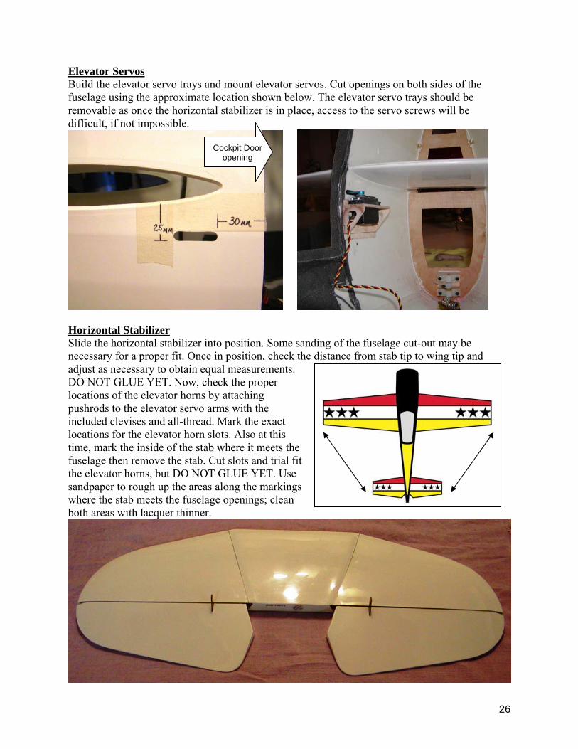
Elevator Servos Build the elevator servo trays and mount elevator servos. Cut openings on both sides of the fuselage using the approximate location shown below. The elevator servo trays should be removable as once the horizontal stabilizer is in place, access to the servo screws will be difficult, if not impossible.
Horizontal Stabilizer Slide the horizontal stabilizer into position. Some sanding of the fuselage cut-out may be necessary for a proper fit. Once in position, check the distance from stab tip to wing tip and adjust as necessary to obtain equal measurements. DO NOT GLUE YET. Now, check the proper locations of the elevator horns by attaching pushrods to the elevator servo arms with the included clevises and all-thread. Mark the exact locations for the elevator horn slots. Also at this time, mark the inside of the stab where it meets the fuselage then remove the stab. Cut slots and trial fit the elevator horns, but DO NOT GLUE YET. Use sandpaper to rough up the areas along the markings where the stab meets the fuselage openings; clean both areas with lacquer thinner.
Cockpit Door opening

27
Use strong, clear packing tape to wrap around the leading edge of the elevator where it slides inside of stab trailing edge. The tape will create a slick, rounded edge that will prevent interference with elevator operation.
Tape should also be applied to aileron leading edges in the same manner.
Install stab into fuselage slot. Again, check that the stab is centered in the fuselage and that the relationship of stab tips to wing tips is equal. Once you are satisfied with the stab location, use medium CA glue along the inside of the stab/fuselage junction. Once set, rough up elevator horns and epoxy into place using the same technique as was used on the aileron horns.
Packing tape wrapped around leading edge of
elevator
NOTE: Elevator pushrod (all-thread, clevises, jam nuts). Two machine screws w/blind nuts secure elevator servo tray. See that stab fairing (now fiberglass) has been cut out and set in position to check fit. Once satisfied, the fairing can be glued into place. As with aileron horns, relief slots will need to be cut into stab trailing edge to allow full range of elevator travel.
28
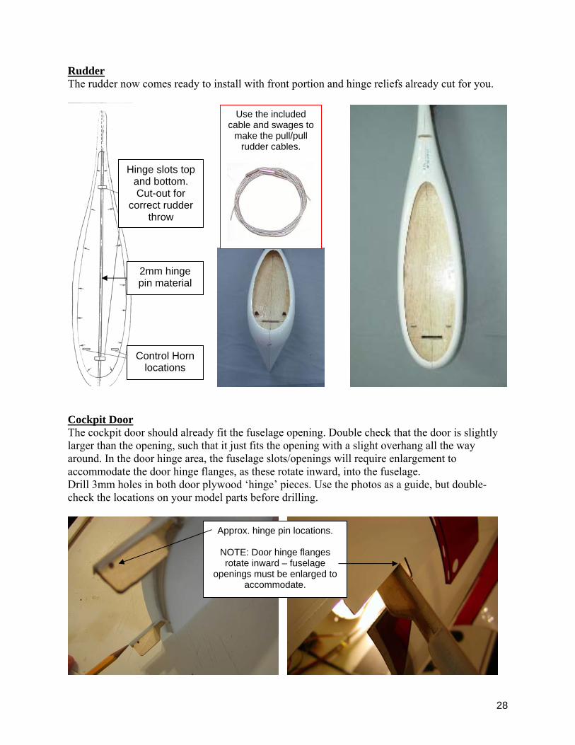
Rudder The rudder now comes ready to install with front portion and hinge reliefs already cut for you.
Cockpit Door The cockpit door should already fit the fuselage opening. Double check that the door is slightly larger than the opening, such that it just fits the opening with a slight overhang all the way around. In the door hinge area, the fuselage slots/openings will require enlargement to accommodate the door hinge flanges, as these rotate inward, into the fuselage. Drill 3mm holes in both door plywood ‘hinge’ pieces. Use the photos as a guide, but double-check the locations on your model parts before drilling.
Hinge slots top and bottom. Cut-out for
correct rudder throw
Control Horn locations
2mm hinge pin material
Approx. hinge pin locations.
NOTE: Door hinge flanges rotate inward – fuselage
openings must be enlarged to accommodate.
Use the included cable and swages to
make the pull/pull rudder cables.
29
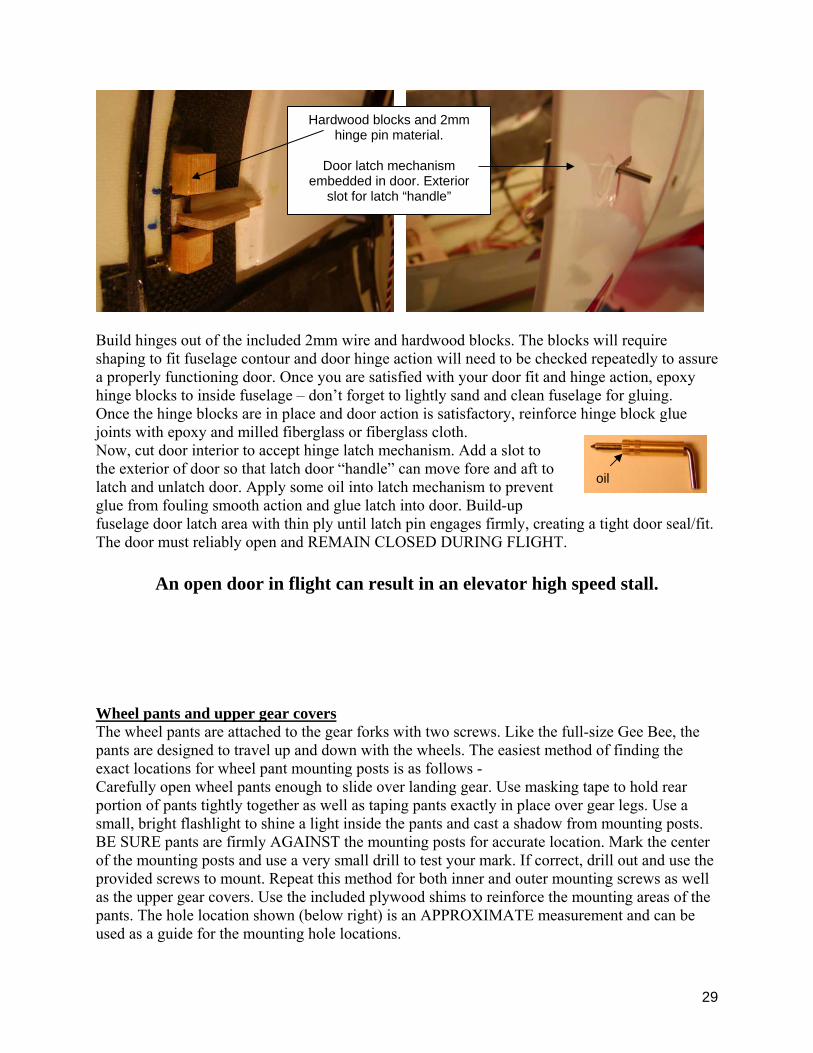
Build hinges out of the included 2mm wire and hardwood blocks. The blocks will require shaping to fit fuselage contour and door hinge action will need to be checked repeatedly to assure a properly functioning door. Once you are satisfied with your door fit and hinge action, epoxy hinge blocks to inside fuselage – don’t forget to lightly sand and clean fuselage for gluing. Once the hinge blocks are in place and door action is satisfactory, reinforce hinge block glue joints with epoxy and milled fiberglass or fiberglass cloth. Now, cut door interior to accept hinge latch mechanism. Add a slot to the exterior of door so that latch door “handle” can move fore and aft to latch and unlatch door. Apply some oil into latch mechanism to prevent glue from fouling smooth action and glue latch into door. Build-up fuselage door latch area with thin ply until latch pin engages firmly, creating a tight door seal/fit. The door must reliably open and REMAIN CLOSED DURING FLIGHT.
An open door in flight can result in an elevator high speed stall.
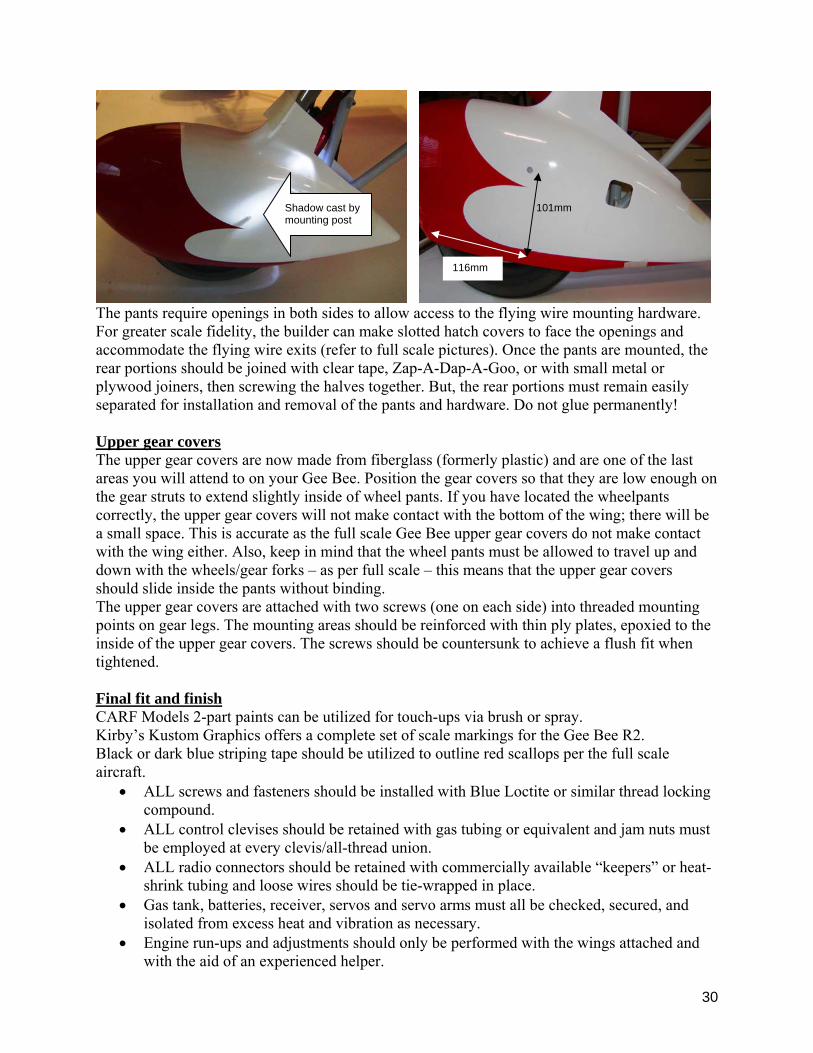
Wheel pants and upper gear covers The wheel pants are attached to the gear forks with two screws. Like the full-size Gee Bee, the pants are designed to travel up and down with the wheels. The easiest method of finding the exact locations for wheel pant mounting posts is as follows - Carefully open wheel pants enough to slide over landing gear. Use masking tape to hold rear portion of pants tightly together as well as taping pants exactly in place over gear legs. Use a small, bright flashlight to shine a light inside the pants and cast a shadow from mounting posts. BE SURE pants are firmly AGAINST the mounting posts for accurate location. Mark the center of the mounting posts and use a very small drill to test your mark. If correct, drill out and use the provided screws to mount. Repeat this method for both inner and outer mounting screws as well as the upper gear covers. Use the included plywood shims to reinforce the mounting areas of the pants. The hole location shown (below right) is an APPROXIMATE measurement and can be used as a guide for the mounting hole locations.
Hardwood blocks and 2mm hinge pin material.
Door latch mechanism
embedded in door. Exterior slot for latch “handle”
oil
30
The pants require openings in both sides to allow access to the flying wire mounting hardware. For greater scale fidelity, the builder can make slotted hatch covers to face the openings and accommodate the flying wire exits (refer to full scale pictures). Once the pants are mounted, the rear portions should be joined with clear tape, Zap-A-Dap-A-Goo, or with small metal or plywood joiners, then screwing the halves together. But, the rear portions must remain easily separated for installation and removal of the pants and hardware. Do not glue permanently! Upper gear covers The upper gear covers are now made from fiberglass (formerly plastic) and are one of the last areas you will attend to on your Gee Bee. Position the gear covers so that they are low enough on the gear struts to extend slightly inside of wheel pants. If you have located the wheelpants correctly, the upper gear covers will not make contact with the bottom of the wing; there will be a small space. This is accurate as the full scale Gee Bee upper gear covers do not make contact with the wing either. Also, keep in mind that the wheel pants must be allowed to travel up and down with the wheels/gear forks – as per full scale – this means that the upper gear covers should slide inside the pants without binding. The upper gear covers are attached with two screws (one on each side) into threaded mounting points on gear legs. The mounting areas should be reinforced with thin ply plates, epoxied to the inside of the upper gear covers. The screws should be countersunk to achieve a flush fit when tightened. Final fit and finish CARF Models 2-part paints can be utilized for touch-ups via brush or spray. Kirby’s Kustom Graphics offers a complete set of scale markings for the Gee Bee R2. Black or dark blue striping tape should be utilized to outline red scallops per the full scale aircraft.
• ALL screws and fasteners should be installed with Blue Loctite or similar thread locking compound.
• ALL control clevises should be retained with gas tubing or equivalent and jam nuts must be employed at every clevis/all-thread union.
• ALL radio connectors should be retained with commercially available “keepers” or heat-shrink tubing and loose wires should be tie-wrapped in place.
• Gas tank, batteries, receiver, servos and servo arms must all be checked, secured, and isolated from excess heat and vibration as necessary.
• Engine run-ups and adjustments should only be performed with the wings attached and with the aid of an experienced helper.
116mm
101mm Shadow cast by mounting post
5
The Gee Bee R2
Accessories Required
• 5 high power servos – (2) Ailerons, (2) Elevator halves; (1) rudder; (1) throttle. All servos used on flying surfaces should have a minimum of 140 in. ounce torque – digital servos are highly recommended for their superior resolution and holding power. Ball bearing outputs and metal gears are a MUST.
• 2400 mah, 6v receiver battery (minimum) • HD switches and servo extensions (22 gauge, minimum) • PCM or 2.4 Ghz radios are recommended for their superior rejection of engine ignition
noise and other ‘RF’ generated by large scale gas aircraft and hardware • CARF Models Tail wheel Unit • CARF Models scale oleo Landing Gear w/wheels • 100cc to 150cc twin cylinder gasoline engine or equivalent – engine must be able to
swing a 26x10 propeller at 6000 rpm (minimum). Equipment placement will require consideration of engine weights to achieve proper CG
• 32 oz. to 50 oz. GASOLINE tank and GAS fuel line Building Materials required
• 30 minute and 3 hr. epoxies • 2 – 5 oz. fiberglass cloth • Milled glass (70 micron) and/or MicroBalloons filler • Thin and Thick CA glues • Blue Loctite • Denatured Alcohol and lacquer thinner • Standard modeling tools

32
TIME TO FLY Like any high performance tail-dragger, the Gee Bee will require some rudder input during its take-off run. If you have flown a large warbird, this should come as no surprise and will be a very similar discipline with the Gee Bee. Throttle up slowly and deliberately, staying ahead of the aircraft; as the tail lifts off, the Gee Bee will achieve flying speed very rapidly and can be rotated immediately. Climb to a safe altitude, turn around, throttle back to approx. 2/3 throttle and trim out the aircraft for hands-off, straight and level flight. This may require several passes as the Gee Bee gobbles up the sky very rapidly. This is, after all, a PYLON RACER! Having an experienced pilot with you during this process can be a great help and comfort. Once the Gee Bee is properly trimmed, try to relax and enjoy your creation. This is, after all, why you built this thing, right?! When you have achieved a level of comfort with the plane, try some high and low speed passes to get the feel for the throttle/rudder coupling. Does this help you or does it make handling more difficult? If you do not find the coupling helpful, disable it via transmitter mixing switch, then repeat the high and low speed passes to get the feel for the Gee Bee as it accelerates and decelerates, noting the required rudder input for both flight envelopes. Also be aware that banking the Gee Bee to the left generally results in a nose-high attitude (at knife edge) due to the right engine thrust and right fin/rudder. Conversely, banking the Gee Bee right will result in a nose-down attitude. Remember, these aircraft were built to do one thing very well – GO FAST AND TURN LEFT. Some compromises must be made in other flight modes. Assuming you have used up about half your fuel, it is now time to set up landing approaches. Start at a fairly high altitude just to confirm you can in fact fly the pattern. Once you can establish a reliable approach and fly the Gee Bee directly down the runway, lower your approach speed. The Gee Bee is NOT a sport plane so do not attempt to line it up and chop the throttle. This airplane must be flown onto the runway – this means the throttle is gently pulled back for a shallow sink rate and maintained at a high idle until touch-down is immanent. ONLY at that moment should the engine be brought back to idle. While some may swear by the 3-point landing, we prefer to default to the full-scale practice of wheel landing the Gee Bee. This process will require plenty of pre-planning on your downwind, base, and final legs to establish touch-down within a reasonable distance. Once the Gee Bee touches down, STAY AHEAD of the rudder. DO NOT RELAX. The Gee Bee landing gear actually provides a very stable landing platform, but rudder input is integral to maintaining directional stability. It is also VERY HELPFUL to apply full up elevator the moment flying speed is lost (generally on touch down) as this will keep the tail planted and reduce the possibility of a nose-over. This is a habit every pilot should adopt any time his airplane is taxiing. CONGRATULATIONS!!! Now that your first flight is behind you and you have had a chance to take a bow, change your shorts, shake many hands and answer a million questions, you should go completely over your Gee Bee. Check EVERYTHING! Assume anything that could have come loose, DID come loose. Check the flying wires, fuel level, battery voltages, every nut, bolt, clevis, screw, and glue joint. Correct any issues and note them in a log for future reference. Note your fuel level in relation to your flight time and adjust your flight-timer accordingly. Now….. fuel up again and fly it again! While it is tempting to pack up and depart as a “hero,” having flown the Gee Bee successfully, you will never master this aircraft until you can fly it without those first-flight jitters and land it consistently. Another couple of flights while the handling of

33
the aircraft is fresh in your mind and you still have a level of confidence, will go a long way towards making you real Gee Bee pilot – and not just a guy who flew a Gee Bee. Epilogue If you ever had a chance to see the real replica, piloted by Delmar Benjamin, you may recall an air show announcer stating that the Gee Bee’s nasty reputation ‘is just all myth,’ in light of Delmar’s expert handling of the plane. This statement is simply wrong, as Delmar willingly affirms: “The Gee Bee R2’s reputation is well-deserved.” It has its idiosyncrasies, as you will discover while exploring other flight modes besides going fast and turning left. This is not to say that the Gee Bee is a bad airplane, anymore than a Boeing 747 is a bad airplane merely because of it’s singleness of purpose… Delmar’s expert pilotage proved that the Granville Brothers and Howell Miller knew very well what they were doing when they built the fastest airplanes in the world; that most the pilots of the day may not have been up to the task of handling them does not tarnish their reputation as state-of-the-art, purpose-built aircraft. The CARF Models Gee Bee R2 replica is no different. Many people will never understand or appreciate the Gee Bee racers. Many find them more amusing, than amazing... That’s OK. One thing is for sure – when you master your R2, you will join a very elite group of flyers whose dedication to this model is appreciated by everyone who has the privilege of watching it fly.
Tallyho!
34
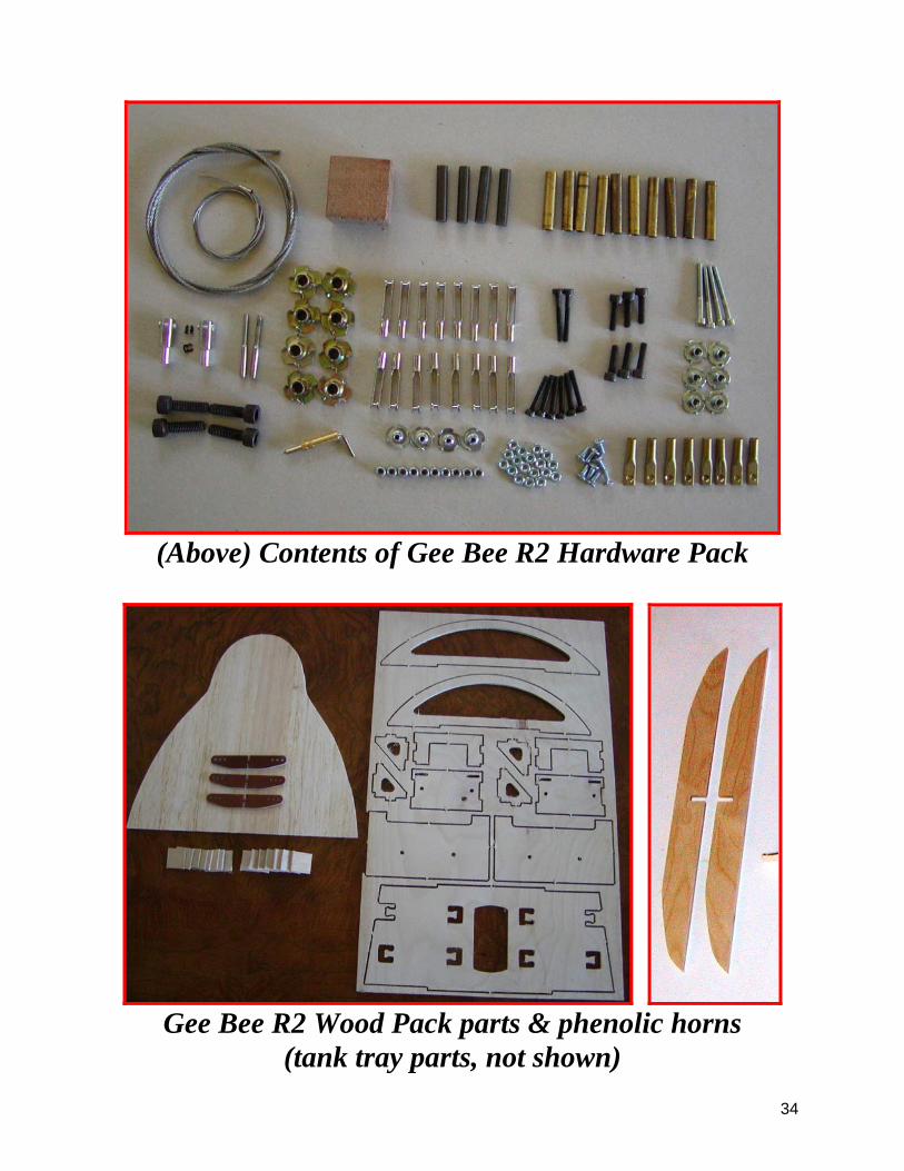
(Above) Contents of Gee Bee R2 Hardware Pack
Gee Bee R2 Wood Pack parts & phenolic horns
(tank tray parts, not shown)

35
(Below) Gee Bee R2 Styrene Parts
(Upper gear covers now made from fiberglass)
Gee Bee R2 Flying Wires, all-thread & hinge wire

36
CARF Models Gee Bee R2 Parts checklist Quantity Description Check 1 Fuselage 1 Right Wing 1 Left Wing 1 Rudder 1 Horizontal Stab 1 Cowling w/Aluminum Mounts 1 Motor Dome 2 Wheel Pants 1 Door, Fiberglass/vacuum plastic assembly 1 Clear plastic sheet, 200 x 300 x 1mm 2 Vacuum Formed Sheets, Gear and Stab Fairing 1 2mm Hinge Pin material, Rudder and Door 4 Flying Wires w/threaded ends 1 All-Thread, M3x1000mm (for linkages) 1 Hardware Bag 1 Milled Wood and phenolic parts bag 1 Instruction Manual