Carck Width
21
-
Upload
piyush-vidyarthi -
Category
Documents
-
view
237 -
download
2
description
civil engineering testing
Transcript of Carck Width


Crack width Measurement in Beams

CRACK WIDTH MEASUREMENT IN BEAMS
The inherent deficiency of the concrete is to resist tension.
In concrete the crack appears as soon as the principal stress increases the tensile
strength of concrete.
The weakening of member starts after the development of the first crack.
The inherent weakness of tension can be reduced to some extent by mixing the
steel fibres in concrete.

Cracking of concrete should not adversely affect the appearance or durability of
the structure; the acceptable limits of cracking would vary with the type of the
structure and environment.
The allowable crack width in reinforced concrete members for buildings are
given in table below:-
Exposure Condition IS 456 BS 8110
1. Normal (in mm) 0.3 0.3
2. Aggressive (mm) 0.1 0.1
Table 1 : Allowable crack width for buildings
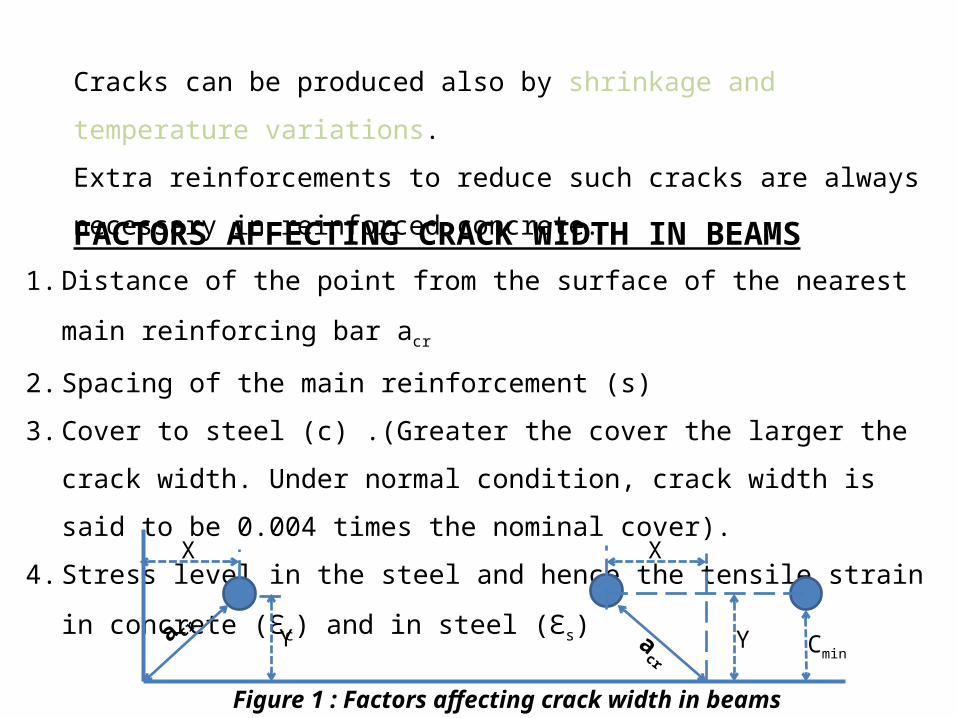
Cracks can be produced also by shrinkage and temperature variations.
Extra reinforcements to reduce such cracks are always necessary in reinforced
concrete.
FACTORS AFFECTING CRACK WIDTH IN BEAMS1. Distance of the point from the surface of the nearest main reinforcing bar acr
2. Spacing of the main reinforcement (s)
3. Cover to steel (c) .(Greater the cover the larger the crack width. Under normal
condition, crack width is said to be 0.004 times the nominal cover).
4. Stress level in the steel and hence the tensile strain in concrete (Ԑc) and in steel
(Ԑs) X
Y
X
Ya cr acr
Cmin
Figure 1 : Factors affecting crack width in beams

On gradual loading of a beam, first cracks are formed when the tensile strain in concrete
reaches the limiting value.
We assume that the reinforcement and the concrete are bonded together and these cracks
are formed at a regular spacing which will release the tensile strength in concrete on both
sides of the cracks as shown below:
Further loading increases the width of the cracks.
With bars having good bond characteristics, there will be no slip between the bar and the
concrete. Hence subsequent secondary cracks are formed to release the strain on further
loading. The width of these cracks will be finer than that of the primary cracks.
P PS
Mean spacing of cracks, Sm
Figure 2: Crack spacing in Beams (P, primary: S, secondary cracks)
MECHANISM OF FLEXURAL CRACKING
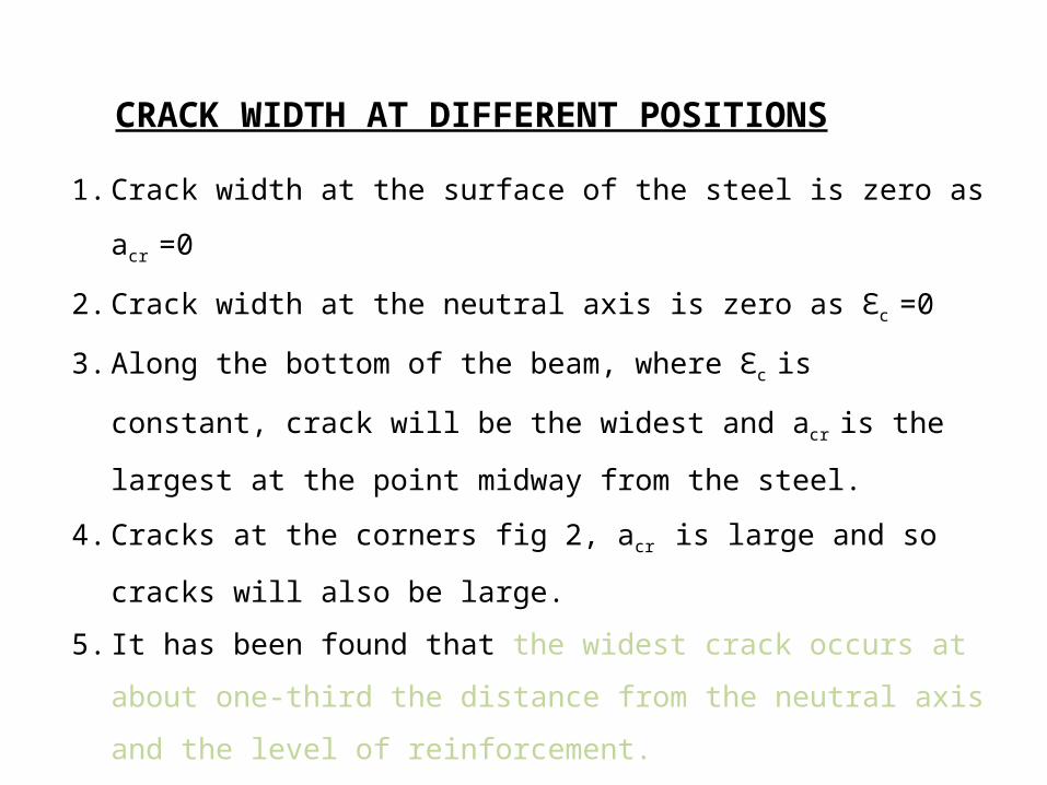
1. Crack width at the surface of the steel is zero as acr =0
2. Crack width at the neutral axis is zero as Ԑc =0
3. Along the bottom of the beam, where Ԑc is constant, crack will be the
widest and acr is the largest at the point midway from the steel.
4. Cracks at the corners fig 2, acr is large and so cracks will also be large.
5. It has been found that the widest crack occurs at about one-third the
distance from the neutral axis and the level of reinforcement.
CRACK WIDTH AT DIFFERENT POSITIONS
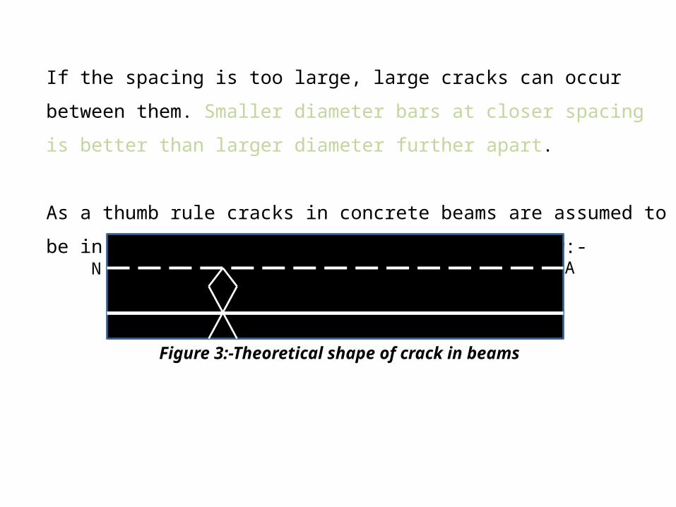
If the spacing is too large, large cracks can occur between them. Smaller diameter
bars at closer spacing is better than larger diameter further apart.
As a thumb rule cracks in concrete beams are assumed to be in the form of
diamond shape as shown below:-
N A
Figure 3:-Theoretical shape of crack in beams
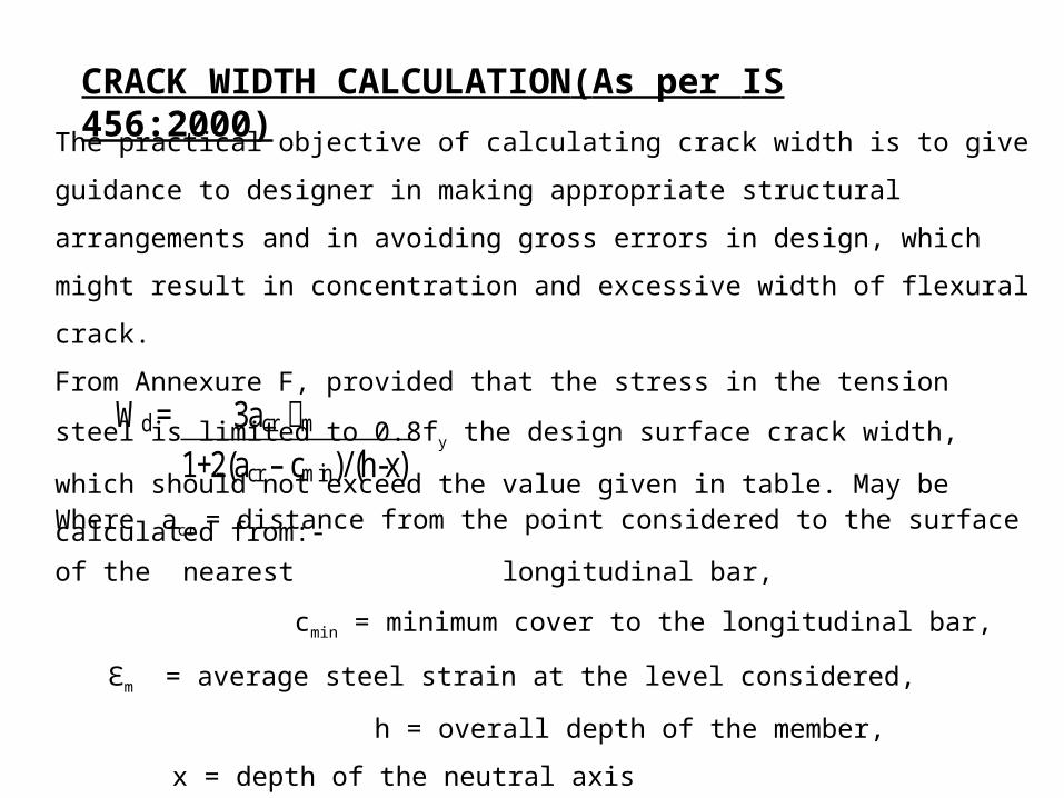
CRACK WIDTH CALCULATION(As per IS 456:2000)
The practical objective of calculating crack width is to give guidance to designer in making
appropriate structural arrangements and in avoiding gross errors in design, which might
result in concentration and excessive width of flexural crack.
From Annexure F, provided that the stress in the tension steel is limited to 0.8fy the design
surface crack width, which should not exceed the value given in table. May be calculated
from:-Wd = 3acr m ഌ 1+2(acr – cmin)/(h-x)
Where acr = distance from the point considered to the surface of the nearest
longitudinal bar,
cmin = minimum cover to the longitudinal bar,
Ԑm = average steel strain at the level considered,
h = overall depth of the member,
x = depth of the neutral axis

The average steel strain Ԑm may be calculated on the basis of the following
assumptions:-
The concrete and steel are both considered to be fully elastic in tension and
compression.
The elastic modulus of the steel may be taken as 200kN/mm2
and the elastic modulus of concrete is derived from E=5000fs/Ec fc
fs/Es fs
h
As
STRAIN STRESS

For a rectangular beam
Ԑm = Ԑ1 - b(h-x)(a-x)
3ESAS(d-x)
Where
As= area of the reinforcement,
b = width of the section
Ԑ1= strain at the level considereda = distance from the compression face to the point at which the
crack is being calculated,d = effective depth

EXPERIMENTAL PROGRAM MATERIALS
The materials used were Portland cement, Natural river sand and crushed stone.The concrete mix proportions is given below:-
CONSTITUENTS QUANTITY(kg/m3)
Cement (OPC Grade 43) 300
Sand( Natural River Sand) 750
Crushed Stone(Max. size 12mm) 1150
Water 165

TEST SPECIMENTable shows the details of the test specimens for the study.
In beams deformed high strength steel bars of dia.20mm were used as longitudinal
tension reinforcement and of dia.10mm as shear reinforcement respectively.
h=35
0
d=30
5
b=200
The sectional details of the beam specimen is shown below:-
ɸ 10
ɸ 20
ɸ 10 @ 250
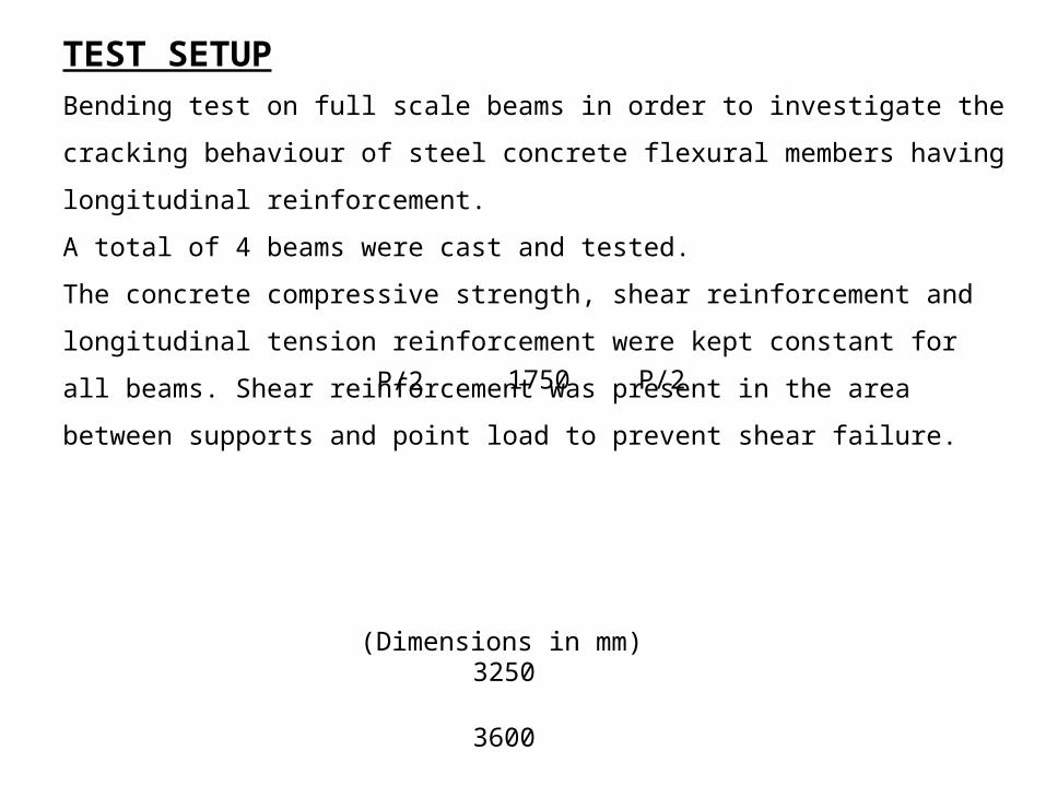
3600
3250
1750P/2 P/2
(Dimensions in mm)
TEST SETUPBending test on full scale beams in order to investigate the cracking behaviour of steel
concrete flexural members having longitudinal reinforcement.
A total of 4 beams were cast and tested.
The concrete compressive strength, shear reinforcement and longitudinal tension
reinforcement were kept constant for all beams. Shear reinforcement was present in the
area between supports and point load to prevent shear failure.
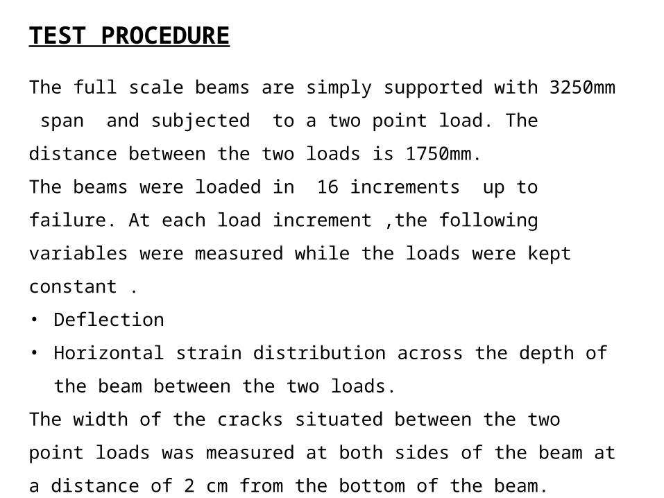
TEST PROCEDURE
The full scale beams are simply supported with 3250mm span and subjected
to a two point load. The distance between the two loads is 1750mm.
The beams were loaded in 16 increments up to failure. At each load increment
,the following variables were measured while the loads were kept constant .
• Deflection
• Horizontal strain distribution across the depth of the beam between the
two loads.
The width of the cracks situated between the two point loads was measured at
both sides of the beam at a distance of 2 cm from the bottom of the beam.
The accuracy of the crack measurement device was 0.02mm.

TEST RESULTSThe given figure shows the crack pattern of the different beams
Figure 4:-Crack Pattern
At the serviceability limit state, which corresponds to the bending moment in the area
between loads of about 48kNm

Questionnaire:
Q. State the various practical applications of a rebar locator.
Ans:- Acceptance inspection of cover after formwork is removed
■ Locates rebars that need to be avoided when drilling holes
■ Provides essential data (location, cover, diameter of rebars) for strength
calculations of reinforced concrete structures
■ Measuring concrete cover depth
■ Quality assurance in mass production of prefabricated concrete elements

Q. Write down the accuracy limits for a rebar locator as per BS:1881
Ans:- Accuracy required by BS 1881: Part 204: ± 2 mm
Q. Mention the crack width limits for members of a building as per IS:456
Ans:-
Q. What are the factors on which the crack width of a beam depends?
Ans:- Distance of the point from the surface of the reinforcing bar acr
Spacing of the main reinforcement (s)
Cover to steel (c)
Tensile strain in concrete (Ԑc) and in steel (Ԑs)
Exposure Condition IS 456 BS 8110
1. Normal (in mm) 0.3 0.3
2. Aggressive (mm) 0.1 0.1

Q. Define primary and secondary cracks in beams.
Ans:- When the tensile strain in concrete reaches the limiting value the initial cracks
formed are known as Primary Cracks.
Further loading increases the width of the cracks, and the cracks thus formed are
secondary cracks in beams.
Q. Draw the figure showing the theoretical shape of crack in beams
Ans:-
N A
Figure 3:-Theoretical shape of crack in beams
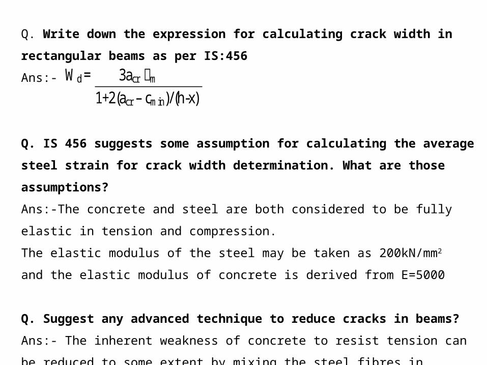
Q. Write down the expression for calculating crack width in rectangular beams as per IS:456
Ans:-
Q. IS 456 suggests some assumption for calculating the average steel strain for crack width
determination. What are those assumptions?
Ans:-The concrete and steel are both considered to be fully elastic in tension and
compression.
The elastic modulus of the steel may be taken as 200kN/mm2
and the elastic modulus of concrete is derived from E=5000
Q. Suggest any advanced technique to reduce cracks in beams?
Ans:- The inherent weakness of concrete to resist tension can be reduced to some extent by
mixing the steel fibres in concrete.
Wd = 3acr m ഌ 1+2(acr – cmin)/(h-x)

THANK YOU…

![[width=0.2]LogoMines [width=0.3]LogoINRIA [width=0.15 ...](https://static.fdocuments.us/doc/165x107/6201e72d8bfe977ad8268cb6/width02logomines-width03logoinria-width015-.jpg)