A Guide to Fiber-Reinforced Polymer Trail Bridges A Guide to Fiber-Reinforced Polymer Trail Bridges

Carbon Fiber Reinforced Polymer Integrated
Antenna Module
Gerald Artner∗† Robert Langwieser∗ Richard Zemann‡
Christoph F. Mecklenbrauker∗†
Abstract — Rising demand for vehicular communi-cation and cooperative movement have led to an in-crease of vehicle mounted antennas. A carbon fiberreinforced polymer cavity is presented, that can beintegrated into the vehicle chassis. The concealedcavity is large enough to house the anticipated an-tennas for present and future vehicular communica-tion. Influence of the cavity onto antennas is demon-strated with calibrated gain measurements on theexample of a 5.9 GHz monopole antenna for intel-ligent transportation systems. The cavities impacton antenna performance is found to be much smallerthan influences of the car itself.
1 INTRODUCTION
Vehicles house a large variety of antennas to ensurereliable communication with their surroundings atradio frequencies (RF). Typical services include po-sitioning systems, mobile communication, recep-tion of television and radio programs, broadcast-ing of emergency messages, radar, and machine-to-machine communication to enable cooperativemovement with other vehicles.
Protruding antenna modules increase the dragcoefficient of vehicles, get damaged more easily andtheir aesthetics are a concern for consumer prod-ucts (e.g. automotive modules on car roofs [1]).Concealed antenna modules allow antenna devel-opment independent from mechanical and aerody-namic considerations. An automotive concealedantenna for Satellite Digital Audio Radio Services(SDARS) inside a 40 mm× 40 mm× 10 mm cavity,along with measured gain patterns and a test drive,was presented in [2]. Automotive antennas are alsobuilt into the windows and bumpers [3] and sidemirrors [4]. An antenna for an aircraft distancemeasurement equipment (DME) inside a cavity ispresented in [5].
A large cavity antenna module is proposed whichcan be manufactured as part of the vehicle chassis.The cavity is big enough to house already exist-ing concealed antenna designs and provides enough
∗Institute of Telecommunications, Technische UniversitatWien, Austria, Gußhausstraße 25, 1040 Vienna, Austria,e-mail: [email protected]†Christian Doppler Laboratory for Wireless Technologies
for Sustainable Mobility‡Institute for Production Engineering and Laser Technol-
ogy, Technische Universitat Wien, Austria
space to meet future requirements. A prototypemade from carbon fiber reinforced polymer (CFRP)is presented to show the feasibility of such a cavityfrom both a mechanical and high frequency stand-point.
2 CARBON FIBER REINFORCEDPOLYMER
Carbon fiber reinforced polymer (CFRP) is a com-posite material consisting of reinforcing fibers in acontinuous polymer matrix. This material class isone of the biggest advancements in the field of lightweight structural materials. Especially the mobilitysector uses the advantages of CFRP such as highstiffness and strength, low density (1600 kg/m3),corrosion and chemical resistance and absorptionof energy (crash elements).
At the beginning of the production process amold is needed, in which the fiber material is get-ting combined with the polymer resin system. Thecuring can also be done in this mold. There aremany different technologies available to performthis production step. The aeronautical industryand the motor sport industry use preimpregnatedmaterials (prepreg) and an autoclave for the cur-ing. That way, a low and constant resin content isachievable, but the efforts for this technology arehigh. Especially the automotive industry, whichhas to produce thousands of pieces per part, is try-ing to use other technologies like the resin transfermolding (RTM). RTM starts with a dry fiber sys-tem that is called preform. This preform has opti-mized fiber amounts and orientations. In the moldthe preform is getting infiltrated with the resin sys-tem and the chemical reaction starts. At the mo-ment cycle times of some minutes are achievablewith this technology.
After this production step the parts have to bemechanically machined to get the necessary part di-mensions or to trim resin canals before the assemblycan be done. These process steps are also neces-sary due to the behavior of CFRP demand and thecost intensity. During the machining damages likefraying, delamination or splintering [6] can occur.Another problem is the highly abrasive character-

Figure 1: CFRP prototype of the antenna module,debagged specimen after the curing in the auto-clave. All dimensions are in millimeter.
istic of CFRP [7] which is dependent on the highertool wear in comparison to the machining of steelor aluminum. So there are many additional effortsin comparison to the production process of metallicparts, which have to be managed before the fiberreinforced polymer can create benefits out of thematerial advantages.
Like its mechanical properties, the electromag-netic properties of CFRP are a mixture of its com-ponents. The carbon-fibers are (poor) electric con-ductors, the matrix is typically a dielectric. Theconductivity of CFRP is frequency dependent andanisotropic [8]. In practice often woven plies areused and the RF properties of the final part thenalso depend on ply weave and layup. Measure-ment results of a patch antenna on a CFRP groundplane and a slot antenna in CFRP are presented in[9]. For three CFRP ground planes the influenceon the radiation patterns of monopole antennas for2.45 GHz and 5.9 GHz were found to be negligible[10]. Measurements of the two vehicle-to-vehicle(V2V) antennas in an automotive antenna modulemounted on a CFRP car roof are presented in [11].Only small differences in performance due to theCFRP roof were measured.
3 THE ANTENNA MODULE
The used specimen geometry for the experimentsis a plate with 1 m×1 m and a central rectangularcavity with inclined walls. Dimensions are depictedin Figure 1. All edges are manufactured with a ra-dius of 5 mm. The cavity offers significantly morespace than current automotive antenna modules.Not only does the cavity provide enough space forthe antennas of future vehicular services, it also al-lows to move RF hardware close to the antennas,
Figure 2: LDS monopole antenna inside the CFRPintegrated chassis module. The depicted coordinatesystem is displaced to increase visibility, the originis in the center of the cavity.
thus eliminating the need to route coaxial cables.Furthermore, antennas can be better separated.
The autoclave method was chosen to producehigh quality components. As mold material aRaku-Tool WB-0700 tooling material is used. Thegeometry was automatically produced with a ma-chining center. Before the production of the layupthe mold is treated with the Chemlease MPP 712EZ and the Chemlease PMR EZ to create a sealedsurface.
The composite part is constructed orthotropicwith two fiber axis at 0 and 90 degrees. The usedmaterial is an Isovolta prepreg with 200 g/m2 areaweight, plain weave and an epoxy resin with in-termediate coefficient of glass temperature. Thereare eight layers of this fabric stacked as [(0◦/90◦)4]to produce a part thickness of around 2 mm. Theresulting resin content is about 30 percent. Thecuring is done in an autoclave at 4 bar and 130 ◦Cfor 3 hours. Four specimen are produced thisway to generate constant part behavior for furtherexperiments. One of the specimen is shown inFigures 1 and 2.
4 ANTENNA MEASUREMENTS
In this section measurement results for a 5.9 GHzmonopole antenna for V2V communication are pre-sented. The antenna was manufactured with thelaser direct structuring (LDS) process from LPKFand is mounted on a square aluminum ground planewith 150 mm side length. The additional groundplane is used because proper contacting of the thinCFRP sheet is hard and to negate a possible re-duction in radiation efficiency due to losses in aCFRP ground plane [12]. Calibrated gain measure-ments were performed inside the institutes anechoicchamber. The CFRP cavity prototype with the
4 4.5 5 5.5 6 6.5 7 7.5 8−14
−12
−10
−8
−6
−4
−2
0
frequency / GHz
|S11
| / d
B
LDS monopole on small ground planeLDS monopole inside the cavity
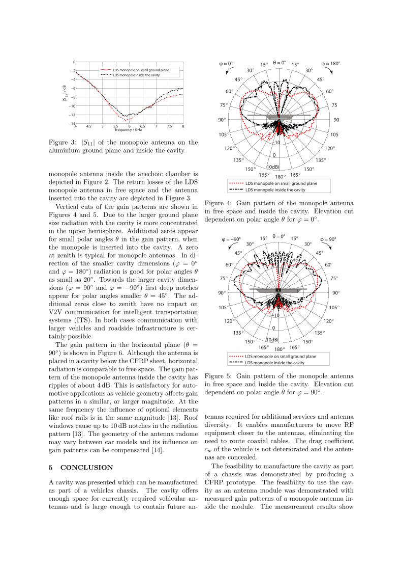
Figure 3: |S11| of the monopole antenna on thealuminium ground plane and inside the cavity.
monopole antenna inside the anechoic chamber isdepicted in Figure 2. The return losses of the LDSmonopole antenna in free space and the antennainserted into the cavity are depicted in Figure 3.
Vertical cuts of the gain patterns are shown inFigures 4 and 5. Due to the larger ground planesize radiation with the cavity is more concentratedin the upper hemisphere. Additional zeros appearfor small polar angles θ in the gain pattern, whenthe monopole is inserted into the cavity. A zeroat zenith is typical for monopole antennas. In di-rection of the smaller cavity dimensions (ϕ = 0◦
and ϕ = 180◦) radiation is good for polar angles θas small as 20◦. Towards the larger cavity dimen-sions (ϕ = 90◦ and ϕ = −90◦) first deep notchesappear for polar angles smaller θ = 45◦. The ad-ditional zeros close to zenith have no impact onV2V communication for intelligent transportationsystems (ITS). In both cases communication withlarger vehicles and roadside infrastructure is cer-tainly possible.
The gain pattern in the horizontal plane (θ =90◦) is shown in Figure 6. Although the antenna isplaced in a cavity below the CFRP sheet, horizontalradiation is comparable to free space. The gain pat-tern of the monopole antenna inside the cavity hasripples of about 4 dB. This is satisfactory for auto-motive applications as vehicle geometry affects gainpatterns in a similar, or larger magnitude. At thesame frequency the influence of optional elementslike roof rails is in the same magnitude [13]. Roofwindows cause up to 10 dB notches in the radiationpattern [13]. The geometry of the antenna radomemay vary between car models and its influence ongain patterns can be compensated [14].
5 CONCLUSION
A cavity was presented which can be manufacturedas part of a vehicles chassis. The cavity offersenough space for currently required vehicular an-tennas and is large enough to contain future an-
15°30°
45°
60°
75°
90°
105 °
120 °
135 °
150 °165 ° 180 ° 165°
150°
135°
120°
105
90
75
60°
45°
30° 15°
−20
−10
0
10dBi
φ = 0° φ = 180°θ = 0°
LDS monopole on small ground planeLDS monopole inside the cavity
Figure 4: Gain pattern of the monopole antennain free space and inside the cavity. Elevation cutdependent on polar angle θ for ϕ = 0◦.
15°30°
45°
60°
75°
90°
105 °
120 °
135 °
150 °165 ° 180 ° 165°
150°
135°
120°
105°
90°
75°
60°
45°
30° 15°
−20
−10
0
10dBi
LDS monopole on small ground planeLDS monopole inside the cavity
φ = −90° φ = 90°θ = 0°
Figure 5: Gain pattern of the monopole antennain free space and inside the cavity. Elevation cutdependent on polar angle θ for ϕ = 90◦.
tennas required for additional services and antennadiversity. It enables manufacturers to move RFequipment closer to the antennas, eliminating theneed to route coaxial cables. The drag coefficientcw of the vehicle is not deteriorated and the anten-nas are concealed.
The feasibility to manufacture the cavity as partof a chassis was demonstrated by producing aCFRP prototype. The feasibility to use the cav-ity as an antenna module was demonstrated withmeasured gain patterns of a monopole antenna in-side the module. The measurement results show

15°30°
45°
60°
75°
90°
105 °
120 °
135 °
150 °165 ° ±180 °−165°
−150°
−135°
−120°
−105°
−90°
−75°
−60°
−45°
−30°−15°
−10
0
10dBi
φ = 0°θ = 90°
LDS monopole on small ground planeLDS monopole inside the cavity
Figure 6: Horizontal cut of the gain pattern depen-dent on azimuthal angle ϕ for θ = 90◦
that omnidirectional radiation with the proposedantenna module is possible and reliable communi-cation during cooperative driving is feasible.
Acknowledgment
This work has been funded by the ChristianDoppler Laboratory for Wireless Technologies forSustainable Mobility. The financial support bythe Austrian Federal Ministry of Science, Researchand Economy and the National Foundation for Re-search, Technology and Development is gratefullyacknowledged.
References
[1] E. Ghafari, A. Fuchs, D. Eblenkampand D.N. Aloi, “A Vehicular Rooftop,Shark-fin, Multiband Antenna for theGPS/LTE/cellular/DSRC Systems”, IEEE-APS Topical Conf. on Antennas and Propa-gation in Wireless Commun. (APWC), PalmBeach, Aruba, 2014
[2] J. Kammerer and S. Lindenmeier, “InvisibleAntenna Embedded in the Roof of a Car withHigh Efficiency for Reception of Satellite Digi-tal Audio Radio Services (SDARS)”, EuropeanConf. on Antennas and Propagation (EuCAP),Gothenburg, Sweden, 2013
[3] R.J. Langley and J.C. Batchelor, “Hidden an-tennas for vehicles”, Electronics & Commun.Eng. J. 14, 2002
[4] S. Senega, J. Kammerer and S. Lindenmeier,“Scan-Phase Antenna Diversity for Digital
Satellite Radio (SDARS) in a Single Automo-tive Side Mirror”, European Conf. on Antennasand Propagation (EuCAP), The Hague, TheNetherlands, 2014
[5] L. Rufail and J. Laurin, “Aircraft Cavity-Backed Nonprotruding Wideband Antenna”,IEEE Antennas Wireless Propag. Lett. 11, 2012
[6] R. Zemann, J. Sacherl, W. Hake and F. Ble-icher, “New Measurement Processes to Definethe Quality of Machined Fibre Reinforced Poly-mers”, 25th DAAAM Int. Symp. on IntelligentManufacturing and Automation, 2014
[7] R. Zemann, F. Bleicher, “Challenges in the fieldof machining fibre reinforced polymers”, Vi-enna young Scientists Symp. (VSS), ISBN: 978-3-9504017-0-7, 164 - 165, Vienna, Austria, 2015
[8] H. C. Kim and S. K. See, “Electrical proper-ties of unidirectional carbon-epoxy compositesin wide frequency band”, J. of Physics D: Appl.Physics 23.7, 916, 1990
[9] A. Galehdar, W. S. Rowe, K. Ghorbani,P. J. Callus, S. John, and C. H. Wang, “Theeffect of ply orientation on the performance ofantennas in or on carbon fiber composites”,Progress in Electromagnetics Research 116, 123-136, 2011
[10] G. Artner, R. Langwieser, G. Lasser andC. F. Mecklenbrauker, “Effect of Carbon-FiberComposites as Ground Plane Material on An-tenna Performance”, IEEE-APS Topical Conf.on Antennas and Propagation in Wireless Com-mun. (APWC), Palm Beach, Aruba, 2014
[11] G. Artner, R. Langwieser, “Performance ofan Automotive Antenna Module on a Carbon-Fiber Composite Car Roof”, European Conf.on Antennas and Propagation (EuCAP), Davos,Switzerland, 2016
[12] G. Artner, R. Langwieser, C. F. Meck-lenbrauker, “Material Induced Changes of An-tenna Performance in Vehicular Applications”,IEEE Int. Conf. on Microwaves, Commun.,Antennas and Electronics Systems (COMCAS),Tel Aviv, Israel, 2015
[13] A. Kwoczek, Z. Raida, J. Lacik, M. Poko-rny, J. Puskely and P. Vagner, “Influence of CarPanorama Glass Roofs on Car2Car Communi-cation (Poster)”, IEEE Veh. Networking Conf.(VNC), Amsterdam, The Netherlands, 2011
[14] L. Ekiz, T. Patelczyk, O. Klemp andC. F. Mecklenbrauker, “Compensation ofVehicle-Specific Antenna Radome Effects at 5.9GHz”, Annu. Conf. of the IEEE Industrial Elec-tronics Soc. (IECON), Vienna, Austria, 2013