Carbon Capture and Storage From Coal 22May07 · Carbon Capture and Storage From Coal-based Power...
14
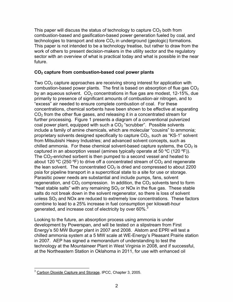
1 Carbon Capture and Storage From Coal-based Power Plants: A White Paper on Technology for the American Public Power Association (APPA) L.D. Carter May 22, 2007 Introduction Technology for carbon capture and storage (CCS) from coal-based electric power plants is rapidly emerging. The component technologies for capture and transport exist, although they are relatively costly compared to other emission control systems (increasing the cost of electricity by over 60%). Technologies for injecting carbon dioxide (CO2) into partially depleted oil reservoirs have been used for enhanced oil recovery (EOR) in the U.S. for over 30 years. Similar techniques have been used since 1990 to inject CO2 into saline reservoirs in Canada, in association with oil and natural gas processing 1 . Additionally, a limited number of power plants have used chemical sorbents to capture CO2 for reuse at very small scale (a few hundred tons per day, or less). 2 However, there is no commercial experience with commercial scale power plants capturing and storing large quantities of CO2 in geologic formations. Additionally, there is no existing regulatory framework that adequately addresses one unique feature of carbon storage: it must be permanent to be effective. The challenge facing industry, and the regulatory community, is to address the technical gaps in integration of the technologies at hand, move aggressively with research and demonstration projects to significantly reduce the cost of more advanced carbon- controlled systems, build an improved understanding of the long-term behavior of CO2 stored underground, and craft a pragmatic risk management framework for conducting CO2 storage. Increasing the difficulty of this challenge is the fact that all of this must be done simultaneously, with limited resources, and at a time when continuous construction of new power plants is necessary to supply a healthy and growing economy. ____________________________ 1 Overview of Acid-Gas Injection Operations in Western Canada, S. Bachu, Alberta Energy and Utilities Board, Edmonton, Canada, http://uregina.ca/ghgt7/PDF/papers/peer/588.pdf . 2 For example: Kerr-McGee/ABB Lummus Crest Process using MEA (Mono-Ethanolamine), Fluor Daniel ECONAMINETM MEA process, Kansai Electric Power Co. / Mitsubishi Heavy Industries, Ltd. (KEPCO/MHI) process using KS-1, KS-2, and KS-3 solvents. Source: Carbon dioxide Capture and Storage , IPCC, 2005, p.116.
Transcript of Carbon Capture and Storage From Coal 22May07 · Carbon Capture and Storage From Coal-based Power...
1
Carbon Capture and Storage From Coal-based Power Plants: A White Paper on Technology
for the American Public Power Association (APPA) L.D. Carter
May 22, 2007 Introduction Technology for carbon capture and storage (CCS) from coal-based electric power plants is rapidly emerging. The component technologies for capture and transport exist, although they are relatively costly compared to other emission control systems (increasing the cost of electricity by over 60%). Technologies for injecting carbon dioxide (CO2) into partially depleted oil reservoirs have been used for enhanced oil recovery (EOR) in the U.S. for over 30 years. Similar techniques have been used since 1990 to inject CO2 into saline reservoirs in Canada, in association with oil and natural gas processing1. Additionally, a limited number of power plants have used chemical sorbents to capture CO2 for reuse at very small scale (a few hundred tons per day, or less).2 However, there is no commercial experience with commercial scale power plants capturing and storing large quantities of CO2 in geologic formations. Additionally, there is no existing regulatory framework that adequately addresses one unique feature of carbon storage: it must be permanent to be effective. The challenge facing industry, and the regulatory community, is to address the technical gaps in integration of the technologies at hand, move aggressively with research and demonstration projects to significantly reduce the cost of more advanced carbon-controlled systems, build an improved understanding of the long-term behavior of CO2 stored underground, and craft a pragmatic risk management framework for conducting CO2 storage. Increasing the difficulty of this challenge is the fact that all of this must be done simultaneously, with limited resources, and at a time when continuous construction of new power plants is necessary to supply a healthy and growing economy. ____________________________ 1
Overview of Acid-Gas Injection Operations in Western Canada, S. Bachu, Alberta Energy and Utilities Board, Edmonton, Canada, http://uregina.ca/ghgt7/PDF/papers/peer/588.pdf . 2 For example: Kerr-McGee/ABB Lummus Crest Process using MEA (Mono-Ethanolamine), Fluor Daniel ECONAMINETM MEA process, Kansai Electric Power Co. / Mitsubishi Heavy Industries, Ltd. (KEPCO/MHI) process using KS-1, KS-2, and KS-3 solvents. Source: Carbon dioxide Capture and Storage, IPCC, 2005, p.116.
2
This paper will discuss the status of technology to capture CO2 both fromcombustion-based and gasification-based power generation fueled by coal, and technologies to transport and store CO2 in underground (geologic) formations. This paper is not intended to be a technology treatise, but rather to draw from the work of others to present decision-makers in the utility sector and the regulatory sector with an overview of what is practical today and what is possible in the near future.
CO2 capture from combustion-based coal power plants
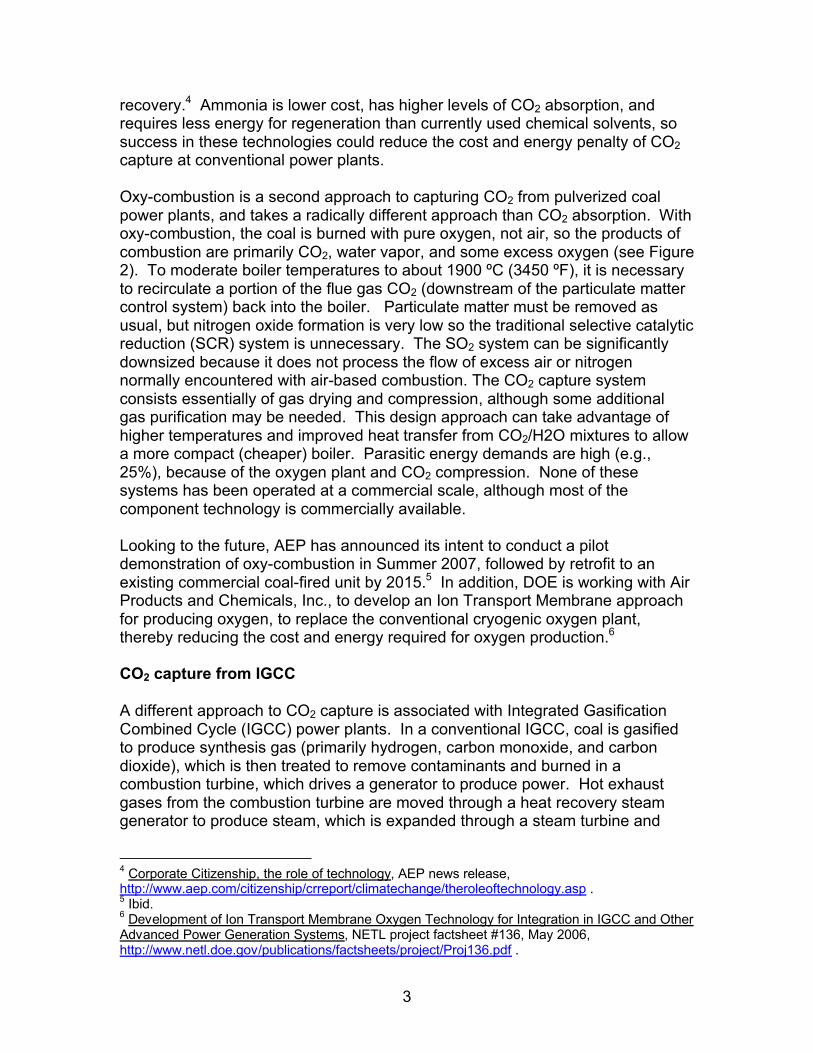
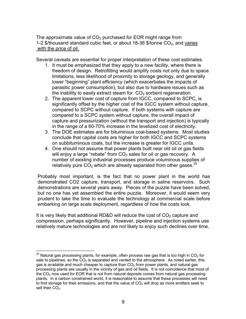
Two CO2 capture approaches are receiving strong interest for application withcombustion-based power plants. The first is based on absorption of flue gas CO2by an aqueous solvent. CO2 concentrations in flue gas are modest, 12-15%, due primarily to presence of significant amounts of combustion-air nitrogen, and to “excess” air needed to ensure complete combustion of coal. For these concentrations, chemical sorbents have been shown to be effective at separating CO2 from the other flue gases, and releasing it in a concentrated stream for further processing. Figure 1 presents a diagram of a conventional pulverized coal power plant, equipped with such a CO2 “scrubber”. Possible solvents include a family of amine chemicals, which are molecular “cousins” to ammonia; proprietary solvents designed specifically to capture CO2, such as “KS-1” solvent from Mitsubishi Heavy Industries; and advanced solvent concepts, such as chilled ammonia. For these chemical solvent-based capture systems, the CO2 is captured in an absorption vessel (amines typically operate at 50 ºC (120 ºF)). The CO2-enriched sorbent is then pumped to a second vessel and heated to about 120 ºC (250 ºF) to drive off a concentrated stream of CO2 and regenerate the lean solvent. The concentrated CO2 is dried and compressed to about 2200 psia for pipeline transport in a supercritical state to a site for use or storage. Parasitic power needs are substantial and include pumps, fans, solvent regeneration, and CO2 compression. In addition, the CO2 solvents tend to form “heat stable salts” with any remaining SO2 or NOx in the flue gas. These stable salts do not break down in the solvent regenerator, so there is loss of solvent unless SO2 and NOx are reduced to extremely low concentrations. These factors combine to lead to a 25% increase in fuel consumption per kilowatt-hour generated, and increase cost of electricity by over 60%.3
Looking to the future, an absorption process using ammonia is under development by Powerspan, and will be tested on a slipstream from First Energy’s 50 MW Burger plant in 2007 and 2008. Alstom and EPRI will test a chilled ammonia system at a 5 MW scale at WE-Energy’s Pleasant Prairie stationin 2007. AEP has signed a memorandum of understanding to test the technology at the Mountaineer Plant in West Virginia in 2008, and if successful, at the Northeastern Station in Oklahoma in 2011, for use with enhanced oil
3 Carbon Dioxide Capture and Storage, IPCC, Chapter 3, 2005.
3
recovery.4 Ammonia is lower cost, has higher levels of CO2 absorption, and requires less energy for regeneration than currently used chemical solvents, so success in these technologies could reduce the cost and energy penalty of CO2capture at conventional power plants.
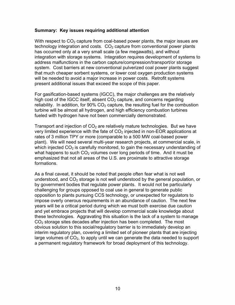
Oxy-combustion is a second approach to capturing CO2 from pulverized coal power plants, and takes a radically different approach than CO2 absorption. With oxy-combustion, the coal is burned with pure oxygen, not air, so the products of combustion are primarily CO2, water vapor, and some excess oxygen (see Figure 2). To moderate boiler temperatures to about 1900 ºC (3450 ºF), it is necessary to recirculate a portion of the flue gas CO2 (downstream of the particulate matter control system) back into the boiler. Particulate matter must be removed as usual, but nitrogen oxide formation is very low so the traditional selective catalytic reduction (SCR) system is unnecessary. The SO2 system can be significantly downsized because it does not process the flow of excess air or nitrogen normally encountered with air-based combustion. The CO2 capture system consists essentially of gas drying and compression, although some additional gas purification may be needed. This design approach can take advantage of higher temperatures and improved heat transfer from CO2/H2O mixtures to allow a more compact (cheaper) boiler. Parasitic energy demands are high (e.g., 25%), because of the oxygen plant and CO2 compression. None of these systems has been operated at a commercial scale, although most of the component technology is commercially available.
Looking to the future, AEP has announced its intent to conduct a pilot demonstration of oxy-combustion in Summer 2007, followed by retrofit to an existing commercial coal-fired unit by 2015.5 In addition, DOE is working with Air Products and Chemicals, Inc., to develop an Ion Transport Membrane approachfor producing oxygen, to replace the conventional cryogenic oxygen plant, thereby reducing the cost and energy required for oxygen production.6
CO2 capture from IGCC
A different approach to CO2 capture is associated with Integrated Gasification Combined Cycle (IGCC) power plants. In a conventional IGCC, coal is gasified to produce synthesis gas (primarily hydrogen, carbon monoxide, and carbon dioxide), which is then treated to remove contaminants and burned in a combustion turbine, which drives a generator to produce power. Hot exhaust gases from the combustion turbine are moved through a heat recovery steam generator to produce steam, which is expanded through a steam turbine and
4 Corporate Citizenship, the role of technology, AEP news release, http://www.aep.com/citizenship/crreport/climatechange/theroleoftechnology.asp .5 Ibid.6 Development of Ion Transport Membrane Oxygen Technology for Integration in IGCC and Other Advanced Power Generation Systems, NETL project factsheet #136, May 2006, http://www.netl.doe.gov/publications/factsheets/project/Proj136.pdf .

4
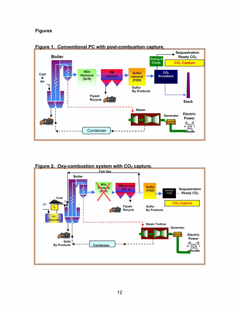
generates additional power (hence, the term “combined cycle”). Rather than capture the CO2 at the end of this process, in an IGCC CO2 is captured prior to combustion of the synthesis gas. This is possible because the synthesis gas can be reacted with water in a catalytic “shift reactor” to convert most of the carbon monoxide to hydrogen and CO2. This leaves a modified synthesis gas consisting largely of hydrogen, water vapor, and CO2, still under the relatively high pressure created in the gasifier. CO2 is much easier to separate in this concentrated, pressurized state, than in normal flue gas. Following H2S removal, a physical solvent process, such as Selexol, can be used to separate the CO2 from the hydrogen. The CO2-rich solvent is then pumped to a separate vessel where concentrated CO2 and lean solvent are regenerated by a reduction in pressure, rather than by the addition of heat as with chemical sorbents (see Figure 3). The hydrogen (instead of CO-rich syngas) is burned in a combustion turbine, and waste heat is used to generate steam which generates additional power, similar to an IGCC without CO2 capture. The inherent advantage of this power generation approach is that the CO2 capture system uses much less parasitic power, and costs less than systems designed for pulverized coal power plants. The inherent disadvantage is that the basic IGCC system (without CO2 capture) remains a relatively immature technology, and costs more than comparably sized pulverized coal system without CO2 capture. For example, Duke Energy estimates the capital cost of its proposed Edwardsport, Indiana, IGCC to be $1.985 billion for the 630 MW facility, or over $3000/kw.7 These costs are substantially higher than recent government reports which projected costs for such systems.8 Complicating this high capital cost is the fact that none of the four existing coal-based IGCCs has met its original design reliability goal with coal. In addition, high-efficiency combustion turbines fueled by hydrogen have not been commercially demonstrated.
It may be possible to reduce the cost of CO2 capture from IGCC systems, and use generation systems that do not require a hydrogen turbine, by capturing less than 90% of the plant’s CO2. For example, DOE’s most recent analysis of IGCC gasifiers indicates that the GE system converts about 30% of the coal carbon into CO2 in the synthesis gas (the rate for the ConocoPhillips design is about 25%, and the Shell system analyzed was much less).9 This CO2 could be captured at lower cost and with much less disruption to the overall plant design that a system including a shift reactor. Alternatively, the gas could be partially shifted, lowering the cost of the shift reaction, and probably leaving enough CO in the syngas to enable use of demonstrated combustion turbines, at the sacrifice of high rates of CO2 capture. However, neither of these systems has been commercially demonstrated, or even well developed in published technical papers providing
7 Edwardsport IGCC FEED Study Report, (Redacted Copy), Duke Energy, as filed with the Indiana Utility Regulatory Commission, 2April2007.8 Cost and Performance Baseline for Fossil Energy Plants – Updated Technical Performance, DOE/NETL, 10April2007, http://www.netl.doe.gov/technologies/coalpower/refshelf.html .9 Ibid.
5
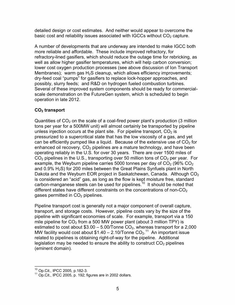
detailed design or cost estimates. And neither would appear to overcome the basic cost and reliability issues associated with IGCCs without CO2 capture.
A number of developments that are underway are intended to make IGCC both more reliable and affordable. These include improved refractory, for refractory-lined gasifiers, which should reduce the outage time for rebricking, as well as allow higher gasifier temperatures, which will help carbon conversion; lower cost oxygen production processes (see above discussion of Ion Transport Membranes); warm gas H2S cleanup, which allows efficiency improvements; dry-feed coal “pumps” for gasifiers to replace lock-hopper approaches, and possibly, slurry feeds; and R&D on hydrogen fueled combustion turbines. Several of these improved system components should be ready for commercial-scale demonstration on the FutureGen system, which is scheduled to beginoperation in late 2012.
CO2 transport
Quantities of CO2 on the scale of a coal-fired power plant’s production (3 milliontons per year for a 500MW unit) will almost certainly be transported by pipelineunless injection occurs at the plant site. For pipeline transport, CO2 is pressurized to a supercritical state that has the low viscosity of a gas, and yet can be efficiently pumped like a liquid. Because of the extensive use of CO2 for enhanced oil recovery, CO2 pipelines are a mature technology, and have been operating reliably in the U.S. for over 30 years. There are over 1500 miles of CO2 pipelines in the U.S., transporting over 50 million tons of CO2 per year. For example, the Weyburn pipeline carries 5000 tonnes per day of CO2 (96% CO2and 0.9% H2S) for 200 miles between the Great Plains Synfuels plant in North Dakota and the Weyburn EOR project in Saskatchewan, Canada. Although CO2is considered an “acid” gas, as long as the flow is kept moisture free, standard carbon-manganese steels can be used for pipelines.10 It should be noted that different states have different constraints on the concentrations of non-CO2gases permitted in CO2 pipelines.
Pipeline transport cost is generally not a major component of overall capture, transport, and storage costs. However, pipeline costs vary by the size of the pipeline with significant economies of scale. For example, transport via a 150 mile pipeline for CO2 from a 500 MW power plant (about 3 million TPY) is estimated to cost about $3.00 – 5.00/Tonne CO2, whereas transport for a 2,000 MW facility would cost about $1.40 – 2.10/Tonne CO2.11 An important issue related to pipelines is obtaining right-of-way for the pipeline. Additional legislation may be needed to ensure the ability to construct CO2 pipelines (eminent domain).
10 Op.Cit., IPCC 2005, p.182-3.11 Op.Cit., IPCC 2005, p. 192; figures are in 2002 dollars.
6
CO2 storage
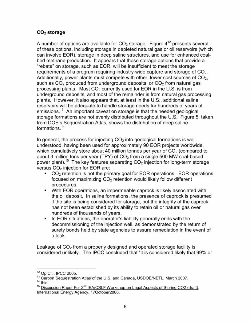
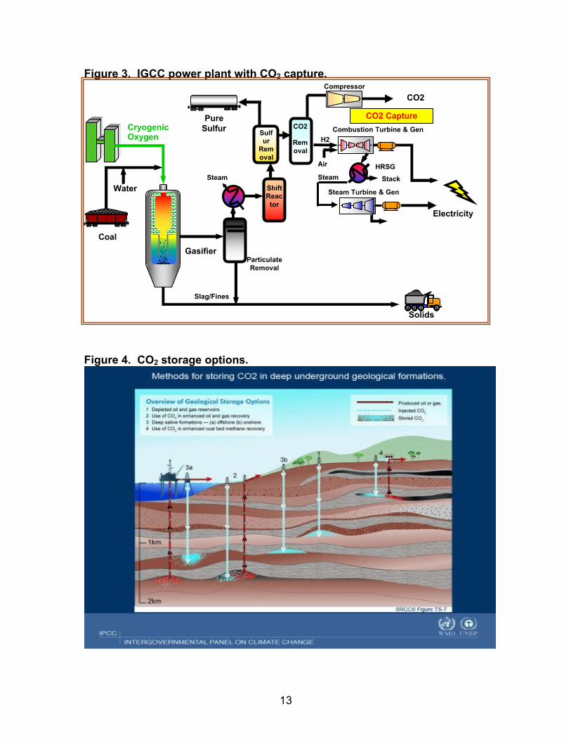
A number of options are available for CO2 storage. Figure 412 presents several of these options, including storage in depleted natural gas or oil reservoirs (which can involve EOR), storage in deep saline structures, and use for enhanced coal-bed methane production. It appears that those storage options that provide a “rebate” on storage, such as EOR, will be insufficient to meet the storage requirements of a program requiring industry-wide capture and storage of CO2. Additionally, power plants must compete with other, lower cost sources of CO2, such as CO2 produced from underground deposits, or CO2 from natural gas processing plants. Most CO2 currently used for EOR in the U.S. is from underground deposits, and most of the remainder is from natural gas processing plants. However, it also appears that, at least in the U.S., additional saline reservoirs will be adequate to handle storage needs for hundreds of years of emissions.13 An important caveat on storage is that the needed geological storage formations are not evenly distributed throughout the U.S. Figure 5, taken from DOE’s Sequestration Atlas, shows the distribution of deep salineformations.14
In general, the process for injecting CO2 into geological formations is well understood, having been used for approximately 90 EOR projects worldwide, which cumulatively store about 40 million tonnes per year of CO2 (compared to about 3 million tons per year (TPY) of CO2 from a single 500 MW coal-based power plant).15 The key features separating CO2 injection for long-term storage versus CO2 injection for EOR are:§ CO2 retention is not the primary goal for EOR operations. EOR operations
focused on maximizing CO2 retention would likely follow different procedures.
§ With EOR operations, an impermeable caprock is likely associated with the oil deposit. In saline formations, the presence of caprock is presumed if the site is being considered for storage, but the integrity of the caprock has not been established by its ability to retain oil or natural gas over hundreds of thousands of years.
§ In EOR situations, the operator’s liability generally ends with the decommissioning of the injection well, as demonstrated by the return of surety bonds held by state agencies to assure remediation in the event of a leak.
Leakage of CO2 from a properly designed and operated storage facility is considered unlikely. The IPCC concluded that “it is considered likely that 99% or
12 Op.Cit., IPCC 2005.13 Carbon Sequestration Atlas of the U.S. and Canada, USDOE/NETL, March 2007.14 Ibid.15 Discussion Paper For 2nd IEA/CSLF Workshop on Legal Aspects of Storing CO2 (draft), International Energy Agency, 17October2006.
7
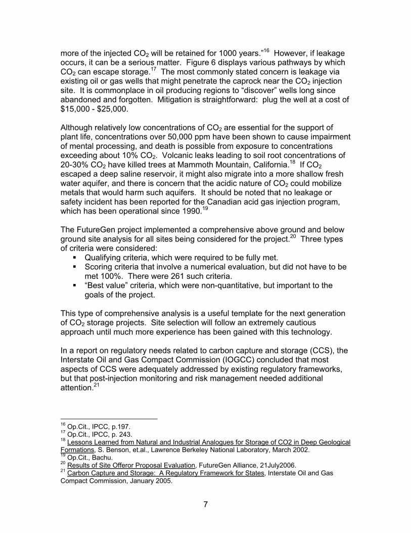
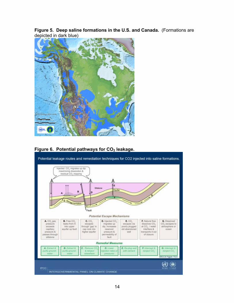
more of the injected CO2 will be retained for 1000 years.”16 However, if leakage occurs, it can be a serious matter. Figure 6 displays various pathways by which CO2 can escape storage.17 The most commonly stated concern is leakage via existing oil or gas wells that might penetrate the caprock near the CO2 injection site. It is commonplace in oil producing regions to “discover” wells long since abandoned and forgotten. Mitigation is straightforward: plug the well at a cost of $15,000 - $25,000.
Although relatively low concentrations of CO2 are essential for the support of plant life, concentrations over 50,000 ppm have been shown to cause impairment of mental processing, and death is possible from exposure to concentrations exceeding about 10% CO2. Volcanic leaks leading to soil root concentrations of 20-30% CO2 have killed trees at Mammoth Mountain, California.18 If CO2escaped a deep saline reservoir, it might also migrate into a more shallow fresh water aquifer, and there is concern that the acidic nature of CO2 could mobilize metals that would harm such aquifers. It should be noted that no leakage or safety incident has been reported for the Canadian acid gas injection program, which has been operational since 1990.19
The FutureGen project implemented a comprehensive above ground and below ground site analysis for all sites being considered for the project.20 Three types of criteria were considered:§ Qualifying criteria, which were required to be fully met.§ Scoring criteria that involve a numerical evaluation, but did not have to be
met 100%. There were 261 such criteria.§ “Best value” criteria, which were non-quantitative, but important to the
goals of the project.
This type of comprehensive analysis is a useful template for the next generation of CO2 storage projects. Site selection will follow an extremely cautious approach until much more experience has been gained with this technology.
In a report on regulatory needs related to carbon capture and storage (CCS), the Interstate Oil and Gas Compact Commission (IOGCC) concluded that most aspects of CCS were adequately addressed by existing regulatory frameworks, but that post-injection monitoring and risk management needed additional attention.21
16 Op.Cit., IPCC, p.197.17 Op.Cit., IPCC, p. 243.18 Lessons Learned from Natural and Industrial Analogues for Storage of CO2 in Deep Geological Formations, S. Benson, et.al., Lawrence Berkeley National Laboratory, March 2002.19 Op.Cit., Bachu.20 Results of Site Offeror Proposal Evaluation, FutureGen Alliance, 21July2006.21 Carbon Capture and Storage: A Regulatory Framework for States, Interstate Oil and Gas Compact Commission, January 2005.
8
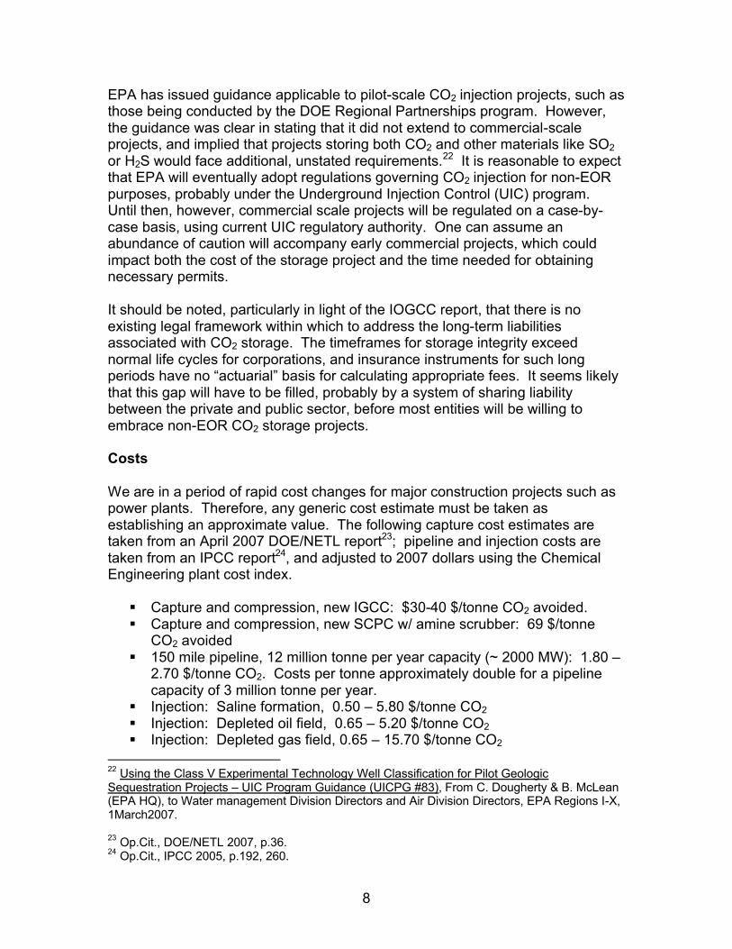
EPA has issued guidance applicable to pilot-scale CO2 injection projects, such as those being conducted by the DOE Regional Partnerships program. However, the guidance was clear in stating that it did not extend to commercial-scale projects, and implied that projects storing both CO2 and other materials like SO2or H2S would face additional, unstated requirements.22 It is reasonable to expect that EPA will eventually adopt regulations governing CO2 injection for non-EOR purposes, probably under the Underground Injection Control (UIC) program. Until then, however, commercial scale projects will be regulated on a case-by-case basis, using current UIC regulatory authority. One can assume an abundance of caution will accompany early commercial projects, which could impact both the cost of the storage project and the time needed for obtaining necessary permits.
It should be noted, particularly in light of the IOGCC report, that there is no existing legal framework within which to address the long-term liabilities associated with CO2 storage. The timeframes for storage integrity exceed normal life cycles for corporations, and insurance instruments for such long periods have no “actuarial” basis for calculating appropriate fees. It seems likelythat this gap will have to be filled, probably by a system of sharing liability between the private and public sector, before most entities will be willing to embrace non-EOR CO2 storage projects.
Costs
We are in a period of rapid cost changes for major construction projects such as power plants. Therefore, any generic cost estimate must be taken as establishing an approximate value. The following capture cost estimates are taken from an April 2007 DOE/NETL report23; pipeline and injection costs are taken from an IPCC report24, and adjusted to 2007 dollars using the Chemical Engineering plant cost index.
§ Capture and compression, new IGCC: $30-40 $/tonne CO2 avoided.§ Capture and compression, new SCPC w/ amine scrubber: 69 $/tonne
CO2 avoided§ 150 mile pipeline, 12 million tonne per year capacity (~ 2000 MW): 1.80 –
2.70 $/tonne CO2. Costs per tonne approximately double for a pipeline capacity of 3 million tonne per year.
§ Injection: Saline formation, 0.50 – 5.80 $/tonne CO2§ Injection: Depleted oil field, 0.65 – 5.20 $/tonne CO2§ Injection: Depleted gas field, 0.65 – 15.70 $/tonne CO2
22 Using the Class V Experimental Technology Well Classification for Pilot Geologic Sequestration Projects – UIC Program Guidance (UICPG #83), From C. Dougherty & B. McLean (EPA HQ), to Water management Division Directors and Air Division Directors, EPA Regions I-X, 1March2007.
23 Op.Cit., DOE/NETL 2007, p.36.24 Op.Cit., IPCC 2005, p.192, 260.
9
The approximate value of CO2 purchased for EOR might range from 1-2 $/thousand standard cubic feet, or about 18-36 $/tonne CO2, and varieswith the price of oil.
Several caveats are essential for proper interpretation of these cost estimates. 1. It must be emphasized that they apply to a new facility, where there is
freedom of design. Retrofitting would amplify costs not only due to space limitations, less likelihood of proximity to storage geology, and generally lower “beginning” plant efficiency (which exacerbates the impacts of parasitic power consumption), but also due to hardware issues such as the inability to easily extract steam for CO2 sorbent regeneration.
2. The apparent lower cost of capture from IGCC, compared to SCPC, is significantly offset by the higher cost of the IGCC system without capture, compared to SCPC without capture. If both systems with capture are compared to a SCPC system without capture, the overall impact of capture and pressurization (without the transport and injection) is typically in the range of a 60-70% increase in the levelized cost of electricity.
3. The DOE estimates are for bituminous coal-based systems. Most studies conclude that capital costs are higher for both IGCC and SCPC systems on subbituminous coals, but the increase is greater for IGCC units.
4. One should not assume that power plants built near old oil or gas fields will enjoy a large “rebate” from CO2 sales for oil or gas recovery. A number of existing industrial processes produce voluminous supplies of relatively pure CO2 which are already separated from other gases.25
Probably most important, is the fact that no power plant in the world has demonstrated CO2 capture, transport, and storage in saline reservoirs. Such demonstrations are several years away. Pieces of the puzzle have been solved, but no one has yet assembled the entire puzzle. Moreover, it would seem very prudent to take the time to evaluate the technology at commercial scale before embarking on large scale deployment, regardless of how the costs look.
It is very likely that additional RD&D will reduce the cost of CO2 capture and compression, perhaps significantly. However, pipeline and injection systems userelatively mature technologies and are not likely to enjoy such declines over time.
25 Natural gas processing plants, for example, often process raw gas that is too high in CO2 for sale to pipelines, so the CO2 is separated and vented to the atmosphere. As noted earlier, this gas is available and much cheaper to capture than CO2 from power plants, and natural gas processing plants are usually in the vicinity of gas and oil fields. It is not coincidence that most of the CO2 now used for EOR that is not from natural deposits comes from natural gas processing plants. In a carbon constrained world, it is reasonable to assume that these processes will need to find storage for their emissions, and that the value of CO2 will drop as more emitters seek to sell their CO2.
10
Summary: Key issues requiring additional attention
With respect to CO2 capture from coal-based power plants, the major issues are technology integration and costs. CO2 capture from conventional power plants has occurred only at a very small scale (a few megawatts), and without integration with storage systems. Integration requires development of systems to address malfunctions in the carbon capture/compression/transport/or storage system. Cost barriers at new conventional pulverized coal power plants suggest that much cheaper sorbent systems, or lower cost oxygen production systems will be needed to avoid a major increase in power costs. Retrofit systems present additional issues that exceed the scope of this paper.
For gasification-based systems (IGCC), the major challenges are the relatively high cost of the IGCC itself, absent CO2 capture, and concerns regarding reliability. In addition, for 90% CO2 capture, the resulting fuel for the combustion turbine will be almost all hydrogen, and high efficiency combustion turbines fueled with hydrogen have not been commercially demonstrated.
Transport and injection of CO2 are relatively mature technologies. But we have very limited experience with the fate of CO2 injected in non-EOR applications at rates of 3 million TPY or more (comparable to a 500 MW coal-based power plant). We will need several multi-year research projects, at commercial scale, in which injected CO2 is carefully monitored, to gain the necessary understanding of what happens to such CO2 volumes over long periods of time. And it must be emphasized that not all areas of the U.S. are proximate to attractive storage formations.
As a final caveat, it should be noted that people often fear what is not well understood, and CO2 storage is not well understood by the general population, or by government bodies that regulate power plants. It would not be particularly challenging for groups opposed to coal use in general to generate public opposition to plants pursuing CCS technology, or unexpected for regulators to impose overly onerous requirements in an abundance of caution. The next few years will be a critical period during which we must both exercise due caution and yet embrace projects that will develop commercial scale knowledge about these technologies. Aggravating this situation is the lack of a system to manage CO2 storage sites decades after injection has been completed. The most obvious solution to this social/regulatory barrier is to immediately develop an interim regulatory plan, covering a limited set of pioneer plants that are injecting large volumes of CO2, to apply until we can generate the data needed to supporta permanent regulatory framework for broad deployment of this technology.

11
About the author – Doug Carter is an independent consultant on energy technology and related environmental issues. His current practice focuses on advising clients regarding advanced coal-based technologies and their potential role in mitigating global climate change. Mr. Carter’s resume includes 25 years with the U.S. Department of Energy, where he was Director of the Office of Planning and Environmental Analysis, within the Office of Fossil Energy. He had previously served with the Office of Enforcement and Office of Air Quality Planning and Standards at the U.S. Environmental Protection Agency. Mr. Carter holds degrees in Mechanical Engineering and Environmental Engineering. He can be reached at [email protected] .
12
Figures
Figure 1. Conventional PC with post-combustion capture.
Figure 2. Oxy-combustion system with CO2 capture.
Boiler
PM removal
(FF or ESP)
Sulfur removal(FGD)
AH2
FlyashRecycle
CO2Scrubbers
Steam Turbine
SulfurBy Products
Generator
Stack
Drying &Comp.
ElectricPower
Coal&
Air
SequestrationReady CO2
CO2 Capture
NOxRemoval
(SCR)
Condenser
Boiler
PM removal(FF or ESP)
Sulfur(FGD)
AH2
FlyashRecycle
Condenser
Coal
Steam Turbine
SulfurBy Products
SolidBy Products
Generator
Flue Gas Recycling
Air Separatio
OAir
ElectricPower
SequestrationReady CO2
Drying &Comp
CO2 Capture
NOxRemoval
(SCR)
13
Figure 3. IGCC power plant with CO2 capture.
Figure 4. CO2 storage options.
CoalGasifier
Slag/Fines
Steam
Cryogenic Oxygen
Particulate Removal
Steam
Combustion Turbine & Gen
HRSGAir
Electricity
StackWater
Solids
Pure Sulfur
CompressorCO2
Shift Reactor
H2
Steam Turbine & Gen
CO2 CaptureCO2
Removal
Sulfur
Removal
14
Figure 5. Deep saline formations in the U.S. and Canada. (Formations are depicted in dark blue)
Figure 6. Potential pathways for CO2 leakage.