Carb
20
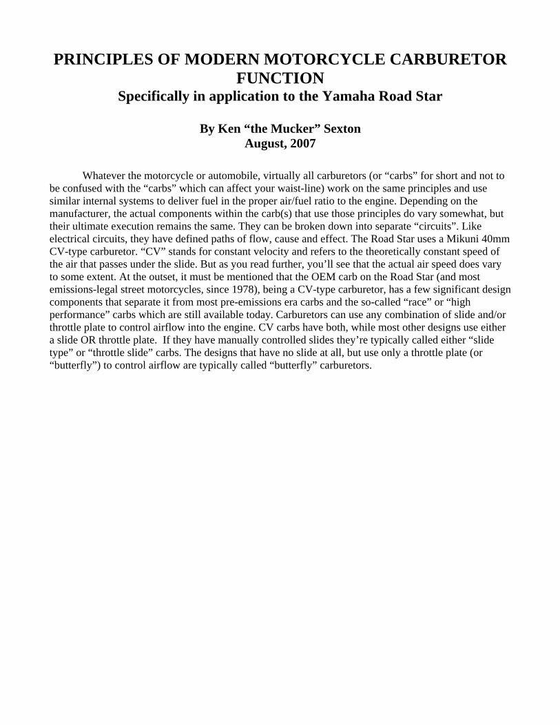
PRINCIPLES OF MODERN MOTORCYCLE CARBURETOR FUNCTION Specifically in application to the Yamaha Road Star By Ken “the Mucker” Sexton August, 2007 Whatever the motorcycle or automobile, virtually all carburetors (or “carbs” for short and not to be confused with the “carbs” which can affect your waist-line) work on the same principles and use similar internal systems to deliver fuel in the proper air/fuel ratio to the engine. Depending on the manufacturer, the actual components within the carb(s) that use those principles do vary somewhat, but their ultimate execution remains the same. They can be broken down into separate “circuits”. Like electrical circuits, they have defined paths of flow, cause and effect. The Road Star uses a Mikuni 40mm CV-type carburetor. “CV” stands for constant velocity and refers to the theoretically constant speed of the air that passes under the slide. But as you read further, you’ll see that the actual air speed does vary to some extent. At the outset, it must be mentioned that the OEM carb on the Road Star (and most emissions-legal street motorcycles, since 1978), being a CV-type carburetor, has a few significant design components that separate it from most pre-emissions era carbs and the so-called “race” or “high performance” carbs which are still available today. Carburetors can use any combination of slide and/or throttle plate to control airflow into the engine. CV carbs have both, while most other designs use either a slide OR throttle plate. If they have manually controlled slides they’re typically called either “slide type” or “throttle slide” carbs. The designs that have no slide at all, but use only a throttle plate (or “butterfly”) to control airflow are typically called “butterfly” carburetors.
Transcript of Carb
PRINCIPLES OF MODERN MOTORCYCLE CARBURETOR FUNCTION
Specifically in application to the Yamaha Road Star
By Ken “the Mucker” Sexton August, 2007
Whatever the motorcycle or automobile, virtually all carburetors (or “carbs” for short and not to
be confused with the “carbs” which can affect your waist-line) work on the same principles and use similar internal systems to deliver fuel in the proper air/fuel ratio to the engine. Depending on the manufacturer, the actual components within the carb(s) that use those principles do vary somewhat, but their ultimate execution remains the same. They can be broken down into separate “circuits”. Like electrical circuits, they have defined paths of flow, cause and effect. The Road Star uses a Mikuni 40mm CV-type carburetor. “CV” stands for constant velocity and refers to the theoretically constant speed of the air that passes under the slide. But as you read further, you’ll see that the actual air speed does vary to some extent. At the outset, it must be mentioned that the OEM carb on the Road Star (and most emissions-legal street motorcycles, since 1978), being a CV-type carburetor, has a few significant design components that separate it from most pre-emissions era carbs and the so-called “race” or “high performance” carbs which are still available today. Carburetors can use any combination of slide and/or throttle plate to control airflow into the engine. CV carbs have both, while most other designs use either a slide OR throttle plate. If they have manually controlled slides they’re typically called either “slide type” or “throttle slide” carbs. The designs that have no slide at all, but use only a throttle plate (or “butterfly”) to control airflow are typically called “butterfly” carburetors.

The OEM Mikuni 40mm Carburetor, as viewed from the intake side. Note: the needle has been
removed in the carb above. If it were in place, it would protrude from the slide, down into the needle jet below the slide (and above the empty port at 6-O’clock).
The throttle plate in a CV carburetor is a flat plate that pivots in the bore of the carb and, when
nearly vertical, almost closes off the airflow into the intake tract, limiting intake flow to just what the engine needs to maintain a consistent idle. When it is opened all the way (directly inline with the carb’s bore) it allows maximum airflow into the engine. In the case of the CV carb, the throttle plate is downstream of the slide, so maximum airflow requires that the throttle be fully opened and that the slide rises to its highest position as well. As a rule, those two requirements do occur at about the same time because you control the throttle plate with your right hand and the slide rises in response to the opening of the throttle butterfly. Non-CV carbs use either a rider-controlled slide as the throttle or they have no slide at all and use only a butterfly valve. Those carbs that have no slide at all are the simplest and oldest design of all carburetors and resemble the ones used on lawn mowers and other engines that don’t require frequent changes in throttle control. Such designs are primitive, because they lack the precision control of fuel & air needed to pass emissions requirements or to give smooth well-controlled engine response, but they do work well in supplying massive amounts of air to engines made to make a lot of power (supercharged configurations being the best example).
It bears mentioning that some of the old types of (mostly) pre-emissions carburetors have a choke plate near the mouth of the carb. It resembles the throttle plate of a CV carb, but it is upstream of any slide or throttle plate and it actually chokes off most of the air from entering the intake tract, hence the name “choke” which we still use to this day, even after the real chokes have been replaced with fuel enrichment systems.

The essential fuel delivery systems are:
#1- The Pilot Circuit (also called the primary, low speed or idle circuit) consists of a brass fuel jet, called the pilot jet (in the float bowl), the pilot mixture screw (PMS), and the pilot air-correction jet (in the perimeter of the carb’s “mouth”). The Pilot circuit delivers its air/fuel mixture through a small hole in the carb’s “throat”, just downstream of where the throttle plate’s lower edge almost touches the carb bore. The pilot circuit regulates the fuel mixture at idle and small throttle openings, typically under one-quarter throttle. The pilot air correction jet (the small brass piece in a recess to the left of a bigger hole at the bottom of the carb “mouth” in the photo above) admits air to the pilot system, through a channel cast into the carb body, above the pilot jet, and it serves as a fuel/air ratio modifier and emulsion improver. This system can only deliver fuel to the engine by utilizing a strong intake vacuum to “suck” the fuel from up the float bowl.
#2- The Midrange Circuit, which is actually a component of the Main system (below), is comprised of
the needle, needle jet, slide assembly and throttle plate assembly. The slide has a diaphragm attached to its top, which serves to isolate the chamber above the slide from atmospheric conditions below it. SU brand carbs and some early motorcycle (Honda) and automotive (Datsun) CV carburetors had a piston-shaped top on the slide, which ran up & down in a machined “cylinder” in the carb top-half. It did the same thing as today’s diaphragm, but it was heavy, more expensive and less responsive to throttle input. The needle, which hangs from the bottom of the slide and moves up & down within the orifice of the needle jet, acts as a “fuel-throttle”, by having a tapered shape to nearly close the needle jet’s opening when the slide is at its lowest position and then to allow full gas flow at its highest position. The midrange system regulates the air/fuel mixture between approximately one-quarter throttle and near-wide open throttle (WFO) and, like the Main Circuit, of which it is a component, it relies on the Venturi Effect to draw fuel up from the float bowl. (Keep reading)
#3- The Main Circuit’s ultimate components include the entire midrange system (above) PLUS the
main jet, emulsion tube (between the main jet and the needle jet) and the main-air correction jet (in the perimeter of the carb’s “mouth”, opposite the pilot air correction jet). The function of the main jet is to limit the total amount of fuel available to the engine at wide-open throttle. The main air correction jet admits air to the main system, through a cast-in channel that connects to the emulsion tube directly above the main jet, and that air also acts as a fuel/air ratio modifier and emulsion improver. While the midrange system uses fuel delivered through the main jet and air from the main correction jet, those jets have little-to-no effect on metering the fuel/air mixture at less than wide open throttle.
#4- The Starter or Enrichener Circuit: There is no true “choke” in the Road Star carb, or in most
modern motorcycle carburetors. That’s because, rather than strangling the intake tract of its air (as real chokes do), it has a circuit that infuses extra fuel directly into the intake tract, thereby enrichening the fuel/air mixture. The enrichener system (we’ll call it a choke for simplicity from now on) requires high intake vacuum downstream of the throttle plate to work. So opening the throttle during startup will actually reduce the choke’s ability to do its job. If the throttle is opened significantly, the “choke” may completely stop delivering any extra fuel, until the throttle is closed enough to regain a high vacuum downstream of the throttle plate. Essentially, if the engine is cold enough to need “choke” to start, leave the throttle grip alone when you hit the starter button.
#5- The deceleration enrichener system is a small device mounted to the side of the carb, containing a
small diaphragm and spring. It adds an additional measure of fuel during the very high intake vacuum that exists during closed-throttle deceleration at road speeds. Its function is to help reduce exhaust backfiring during deceleration. It is not common to all modern motorcycles and it has no readily adjustable functions.
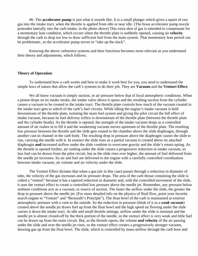
#6- The accelerator pump is just what it sounds like. It is a small plunger which gives a squirt of raw gas into the intake tract, when the throttle is applied from idle or near idle. (The brass accelerator pump nozzle protrudes laterally into the carb intake, in the photo above) This extra shot of gas is intended to compensate for a momentary lean condition, which occurs when the throttle plate is suddenly opened, causing air velocity through the carb to drop too low to draw sufficient fuel from the main system. That momentary lean period can be problematic, so the accelerator pump serves to “take up the slack”.
Knowing the above carburetor systems and their functions becomes more relevant as you understand
their theory and adjustments, which follows. Theory of Operation:
To understand how a carb works and how to make it work best for you, you need to understand the
simple laws of nature that allow the carb’s systems to do their job. They are Vacuum and the Venturi Effect. We all know vacuum is simply suction, or air pressure below that of local atmospheric conditions. When
a piston drops on its intake stroke, the intake valve above it opens and the resulting suction from the cylinder causes a vacuum to be created in the intake tract. The throttle plate controls how much of the vacuum created in the intake tract gets to which of the carb’s fuel circuits. While idling the engine’s intake vacuum is held downstream of the throttle plate, isolating the main fuel system and giving the pilot circuit the full effect of intake vacuum, because its fuel delivery orifice is downstream of the throttle plate (between the throttle plate and the cylinder heads). As the throttle is opened, the strength of the intake vacuum drops as a controlled amount of air rushes in to fill it and the weakening vacuum moves upstream of the throttle plate. The resulting low pressure between the throttle and the slide gets routed to the chamber above the slide diaphragm, through another cast-in channel in the carb body. The resulting drop in pressure above the diaphragm causes the slide to rise, carrying the needle with it. In essence the slide rises as a partial vacuum is created above its attached diaphragm and increased airflow under the slide combine to overcome gravity and the slide’s return spring. As the throttle is opened further, air rushing under the slide causes a progressive reduction in intake vacuum, so less fuel can be drawn from the pilot circuit, but as the slide rises ever higher, the amount of fuel delivered from the needle jet increases. So air and fuel are delivered to the engine with a carefully controlled coordination between intake vacuum, air volume and air velocity under the slide.
The Venturi Effect dictates that when a gas (air in this case) passes through a reduction in diameter of
tube, the velocity of the gas increases and its pressure drops. The area of the carb throat containing the slide is called a “venturi” because it has a tapered reduction in diameter and, with the controlled movement of the slide, it uses the venturi effect to create a controlled low pressure above the needle jet. Remember, any pressure below ambient conditions acts as a vacuum, or source of suction. The faster the airflow under the slide, the greater the drop in pressure above the needle jet. (For more detailed info on the physics of fluid flow, point your favorite search engine to “Venturi” and “Bernoulli’s Principle”). The float bowl of the carb is maintained at exterior atmospheric pressure with a vent to the outside. So the reduction in pressure (think of it as a weak vacuum) created above the needle jet draws fuel up from the float bowl and the high speed air flowing under the slide carries it down the intake tract. At idle and small throttle settings, airflow under the slide is minimal and the needle jet is almost closed-off by the thick portion of the needle, so the venturi effect is very weak and little fuel can be drawn up from the main circuit. But, as the throttle opens, the volume and velocity of the air passing under the slide and over the needle jet rises, so the venturi effect creates a progressively stronger vacuum, drawing gas up from the float bowl. The slide, which is controlled by mass-airflow through the carb bore and
differential pressures between the carb bore and the chamber above its diaphragm, rises and carries the needle with it. The rising needle, with its tapered shape, exposes an ever-greater amount of the needle jet orifice to the venturi, allowing an increasing amount of the fuel to rise from the main system. The result is that, as airflow into the engine increases, so does the amount of gasoline with it.
At idle, the throttle plate nearly closes off the bore of the carb, which results in a strong vacuum downstream of the throttle plate and with the slide at its lowest position, nearly closing off the needle jet with the thickest part of the needle, the pilot circuit regulates fuel flow. As the throttle is opened, allowing more air into the engine, the needle & slide begins to rise, intake vacuum weakens (causing a drop in pilot fuel delivery) and air flow above the needle jet speeds up. The venturi effect creates a low pressure (read: suction) above the needle jet and fuel is drawn up from the midrange/main circuit. As the needle and slide continue to rise, they expose an ever-greater amount of the needle jet orifice to the airflow above it, causing a progressive rise in fuel delivery with the increasing airflow. At WFO the vacuum within the entire intake tract is at its lowest (so the pilot system is virtually shut off), but air velocity (and quantity) above the needle jet is at its highest and the needle jet orifice is uncovered as much as allowed by the needle’s fine tip. So the venturi effect and the needle jet’s opening are maximized and the size of the main jet controls fuel delivery.
But there are no absolutes in carburetors. The fuel circuits “overlap”, so at any given throttle setting,
engine RPM, and engine load there will tend to be some gas delivered to the engine through more than one circuit. As an example, at a steady 60 MPH cruise speed in top gear, the pilot and midrange circuits will both be delivering some fuel, but because the throttle setting is so small, causing a high intake vacuum, the pilot system will be the dominant factor in determining fuel delivery. As the throttle is opened and intake vacuum drops, the pilot system will be progressively “retired” and the needle, needle jet and main jet become more dominant. Conversely, even at idle when the pilot system is the primary fuel metering circuit, airflow above the needle jet will allow some fuel to be delivered from the main system. Because it has such a big engine, the Road Star in particular has a slide which never drops as close to the bottom of the bore as many other motorcycle carbs do, so it has a greater potential “overlap” between the pilot and main systems than many other motorcycles. Having two BIG cylinders to feed requires a lot of air, even at idle. Even at idle, a small amount of gas comes up from the main circuit and at wide open throttle the pilot circuit may still be delivering a very small amount to gas to the intake as well. But the quantities are inconsequential and to all intents and purposes, you can operate on the presumption that the main circuit is “shut off” and idle and the pilot circuit is also at throttle settings above halfway.
When slowing from road speeds with the throttle closed and the clutch engaged, intake vacuum will be
much stronger than it ever is at idle. That’s because the engine is spinning above idle speed and pumping strongly against the closed throttle plate. By way of illustrating this especially strong vacuum, think of a vacuum cleaner with your hand obscuring the hose opening. The vacuum cleaner may be pretty strong in its normal operation, but with your hand almost covering the hose end, the suction may become strong enough to contract the hose. Then when you remove your hand from the hose end, the power of the vacuum drops back to normal and the hose can re-extend. (On some motorcycles with individual carbs mounted in separate rubber manifolds, you can actually see the carb(s) pulse in and out at idle for the same reason. Some of the old “UJM” four cylinder models are great examples of that trait) With two BIG cylinders pumping furiously during deceleration, the pilot circuit may be unable to supply enough fuel to keep the engine from running too lean, so the decal enrichener circuit ads extra fuel to stave off exhaust backfiring.
JETTING:
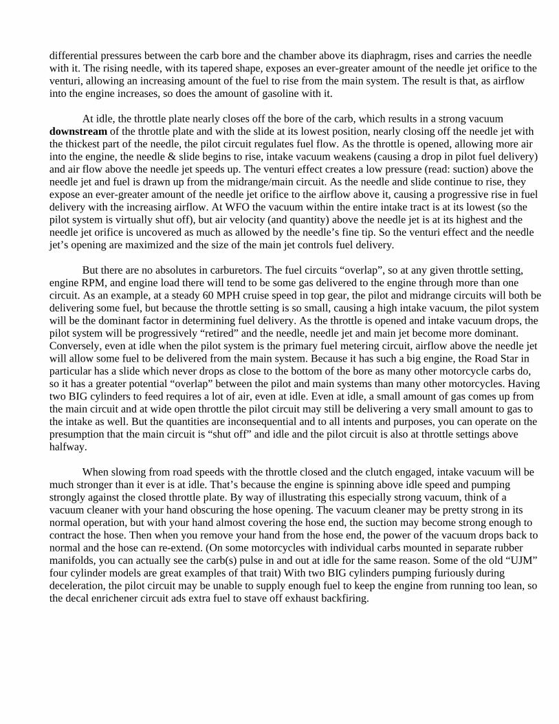
View looking at the jets, from underneath. Note: the Pilot Mixture Screw has been removed in this photo, but it
fits into the tubular protrusion above the large brass plug, which is outside of the float bowl chamber.
Most aftermarket exhaust systems will effect the engine’s breathing enough to call for some recalibration. Changing the air filter and/or entire air-box/filter assembly to a less restrictive design will fairly scream for a jet kit. Failing to properly re-establish the engine’s correct air/fuel mixture after significantly improving the breathing characteristics can cause damage to the engine itself. Why is that? The answer lies in some more theory… A theoretically perfect air/fuel mixture (a ratio of 14:1 air & gasoline, called stoichiometric) burns in a controlled, rapid expansion of flame across the combustion chamber. If the mixture simply explodes violently or if it burns too slowly, the result can be anything from poor performance, poor mileage, reduced “driveability”, or damage to the engine itself. A lean mixture tends to burn too slowly and can be the cause of any combination of the following; hesitation to throttle input, reduced mileage, intake backfiring (“POP!” up the intake tract), exhaust backfiring (“BANG!” from the tail pipe), surging at steady-throttle cruise speeds, and/or engine overheating. It should be stressed that running a little lean is unlikely to harm the engine. If it were running lean enough to do damage, the bike’s driveability will suffer enough to make it evident that something is amiss. A rich mixture burns faster than a lean one, but may cause poor mileage, a smell of unburned gasoline, reduced power, and carbon buildup in the combustion chamber, on the valves and the spark plugs.
In addition to how much gas gets mixed with intake air, how well the gas has been mixed with the air is important to how efficiently the engine runs. If the gas forms large, wet droplets dragged into the combustion chamber by the rush of intake air, it won’t burn thoroughly, give good gas mileage or produce best power. If it is finely atomized with the incoming air (called a dry mixture), it’ll ignite reliably and result in a consistent, controlled ignition that gives the best power and economy. A hot engine benefits good fuel atomization and helps to retain the fuel in a well vaporized state as it travels toward and into the combustion chamber. A cold
engine inhibits fuel atomization and can actually render a fuel/air mixture that started out well-atomized into a wet, poorly mixed spray by the time it gets past the intake valves. Think of heat and cold effecting fuel atomization just as it affects how much water vapor can be retained in the air as humidity or why liquids evaporate when they are exposed to hot surfaces. That’s why you want an engine that needs choke to start when it’s cold, but runs cleanly without choke once it’s warmed up. The choke “fattens” the mixture into a wet overly-rich dose that ignites easily, even if it doesn’t burn as thoroughly. Although it may burn so poorly that some of the gas goes out the tail pipe as unburned hydrocarbons, the extra-rich mixture that the choke produces does help to insure that the mixture ignites reliably. Without the extra gas added by the choke, a cold engine would be difficult to start and run poorly until thoroughly warmed-up.
A fuel mixture which burns excessively slow (as a result of poor atomization or a lean mixture), may
still be burning near the end of the exhaust stroke when the exhaust valves are almost closed and the intake valves are opening (a period in valve timing called “overlap”). In that case, the still-expanding gases may rush up the intake tract and result in a POP! Some riders call that a “cough” (so a backfire out the tail pipe is a fart?). In any case, intake backfiring which is not especially vigorous is more of an annoyance than a danger, as long as you don’t have the air cleaner removed and are standing with your face close to the carb inlet when it happens. That can cause singed eyebrows, among other things. If the engine suffers especially frequent and/or vigorous intake backfiring, it may be a result of problems beyond simply running too lean.
You’ll rejet your carb to improve engine performance, fuel mileage, make it work with alterations to
changes in intake and/or exhaust breathing (K&N filter, free-flowing aftermarket pipes, etc.) or to correct for poor running characteristics related to fuel mixture. Most of the time, this is best accomplished by purchasing a “jet kit” from manufacturers like Dynojet, FactoryPro, Baron’s Custom, K&N, etc. Such kits generally give you a needle with multiple E-clip grooves (compared to the OEM needle with only one groove for the clip), several main jets to accommodate varying intake & exhaust modifications, a drill to facilitate removal of the plug which covers the pilot mixture screw, varying hardware such as float bowl screws, needle adjustment washers (shims) and detailed instructions. Read all instructions that come with the jet kit and you should have no problems.
The following is the typical procedure for rejetting: A jet kit will come with instructions for removing the plug covering the Pilot Mixture Screw (PMS). On
the Road Star’s carburetor it’s located under the carb outlet, adjacent to the float bowl. It is inside a tubular-shaped protrusion, near the carb heater and centered under the carburetor outlet. There is also a flush-mounted brass plug between the PMS and the float bowl, do not attempt to remove or drill out that plug. The plug over the PMS was put there to keep anyone from altering the PMS’s factory settings, which were certified to meet Federal & State emissions standards. If you’re a tree hugger and feeling particularly squeamish about messing with the bike’s exhaust emissions, stop what you’re doing now, return all non-OEM parts to factory conditions, ride the totally stock motorcycle to the nearest Green Peace recruiting station and sign-up. Otherwise, your bike will run fine without the plug over the PMS and, if you do a good job of rejetting the carb, it still won’t cause animals to keel over in its exhaust wake.
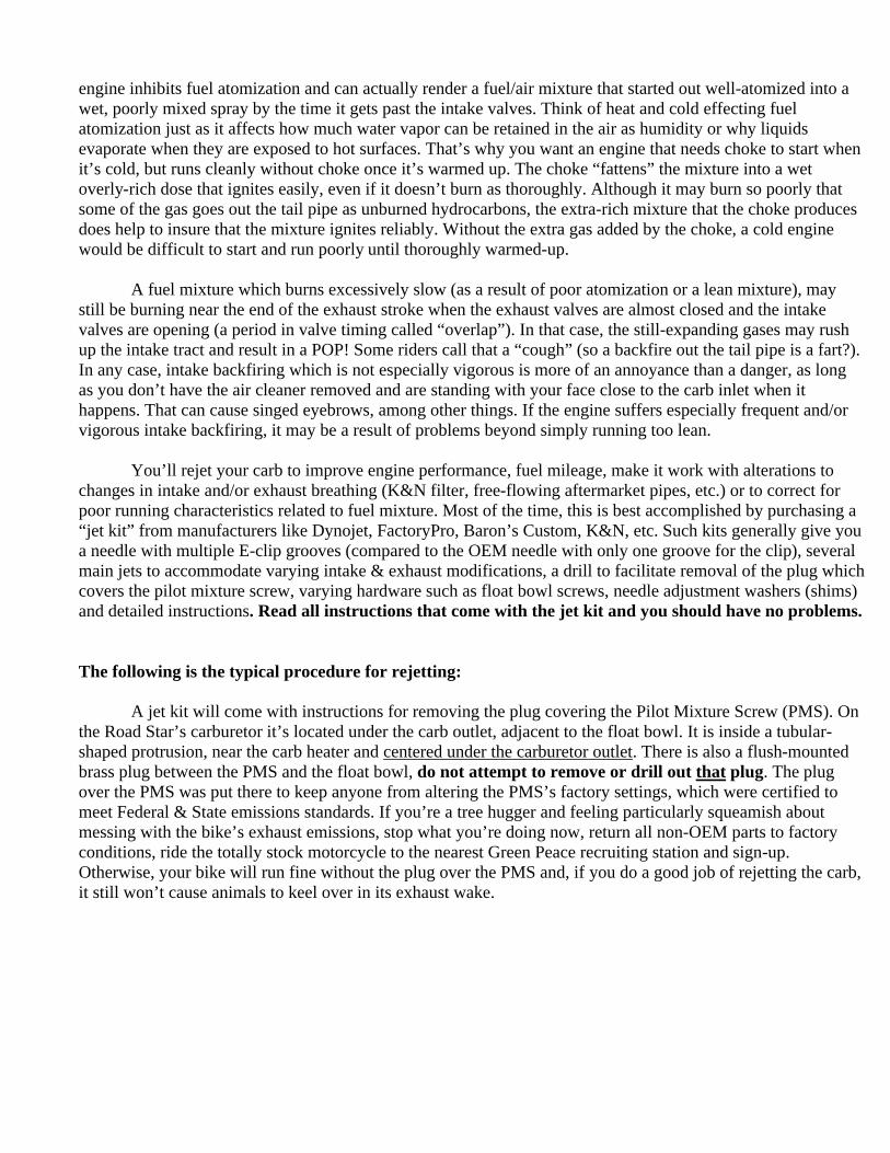
On the left is an adjustable need from a jet kit. On the right is the OEM, nonadjustable needle. The
Baron needle is made from titanium which has far superior wear resistance compared to the aluminum alloy Mikuni part.

In order to make adjustments to the pilot circuit, it is necessary to remove the brass plug over the PMS. Typically you’ll drill a small hole in its center and then screw in a sheetmetal screw, which will be used to pry out the plug. Be careful that when you drill through the plug you don’t allow the drill to drop onto the brass pilot adjustment screw and ruin its screwdriver slot. Once the plug is out of the way, you can use a small screwdriver to make adjustments to the idle/low speed mixture as needed. The PMS is an adjustable jet (car people tend to call them “needle jets”) which allows a fine adjustment of the air/fuel mixture delivered from the pilot air-correction jet AND the pilot (fuel) jet. Start out by screwing in the PMS until it lightly closes onto its seat. Excessive torque will damage the PMS screw and the aluminum seat within the carb casting, so treat it as though the carb were made of glass. With the PMS seated all the way in, if you look into the carb outlet you’ll see the needle-tip of the pilot mixture screw protruding into the bottom of the carb throat. For most purposes, the baseline PMS setting is 3 ½ turns off the seat. So, while counting the revolutions of the screwdriver handle, back it out that much. You’ll back it out more if the engine needs more fuel at idle and during deceleration or you’ll turn it in for a leaner setting. Note: Backing out the PMS on the OEM Mikuni CV-carb richens the mixture because it regulates gasoline coming from the pilot jet, but on most non-CV carbs the PMS meters air (not fuel) and so their function is the reverse; backing them out leans the fuel mixture. If you’re unsure of the type of pilot mixture screw on your non-OEM carburetor, the rule of thumb is the following: if the PMS is located above the gasket surface of the float bowl, it’s probably an air adjustment type. The Mikuni HSR carbs are an example of a design with the PMS next to the carb inlet and above the float bowl. So in their case, the PMS meters air, not fuel. Most modern, non-CV, “smoothbore” or “race” carbs have a PMS that regulates air to the pilot circuit. On carbs with the PMS below the float bowl gasket, it adjusts fuel.
The pilot system also contains a brass pilot jet inside of the float bowl and it sets the maximum amount
of fuel available through the pilot circuit. By exchanging it for one with a higher number, you set a higher potential amount of fuel that the engine can receive during high intake vacuum conditions. The PMS serves as a fine adjustment between no gas at all (seated) and the maximum amount that the orifice in the pilot jet can deliver.
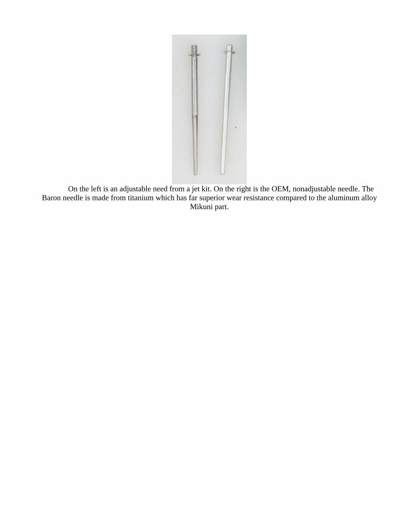
In the photo above, the needle is from a Baron jet kit and it clearly shows the 6 adjustment grooves, for
the E-clip. The thick plastic washer, which comes with the OEM set-up is always placed under the clip. The two small, .5mm thick, metal washers, which come with the jet kit are used to fine-tune the jetting. When placed
under the clip, they raise the needle a “half step”. When placed above the clip, they do nothing to effect jetting. The spring above the needle serves to retain the needle in the bottom of the slide.
The needle’s rate of taper and its height adjustment is the principle method of adjusting the mixture
between idle and wide-open throttle (WFO). The OEM needle can only be adjusted to a richer setting by raising it with the addition of washers placed under its E-clip. Needles that come with jet kits (and aftermarket high-performance carbs, like the Mikuni HSR series) will have either 5 or 6 E-clip grooves cut around their top portion. Needle adjustment is accomplished by selecting a higher or lower groove for the E-clip (sometimes called a “Jesus Clip” because of the exclamation frequently made when the little bastards fly across the shop floor, when you’re trying to slip them into a needle groove). Moving the clip to a higher position (toward the fat end of the needle) drops the needle in the carb and causes a net leaning of the midrange circuit. Conversely, placing the clip in a lower groove raises the needle and richens the mixture. The clip grooves are usually spaced one millimeter apart (.040”). Sometimes a fine adjustment of the needle is called for by placing a half-millimeter thick washer under the clip, accomplishing a “half-step” in needle height adjustment.
The main jet is screwed into the end of a tube (called the emulsion tube), within the float bowl chamber. It is simply exchanged for one with a bigger or smaller orifice, depending on the need for a richer or leaner mixture at WFO. Its number, stamped on the jet face, goes up as the jet opening gets bigger (richer).
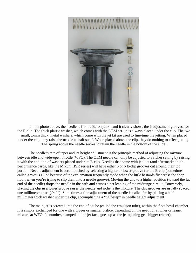
In the photo above, the three brass jets between the white fuel floats are the main jet (in the center of the photo and the most out of focus), the starter jet (smaller in diameter to the main jet and above it in this photo) and the pilot jet (the longer one to the right of the main and starter jets). You'll have no need to alter the starter jet. Whenever the float bowl is removed, use extreme care to be sure not to strike the float. Its fuel level adjusting tang (the “T” shaped silver part near the bottom of the picture), is easily
bent out of adjustment.
At this juncture the accelerator pump is another feature that bears mentioning. It delivers a squirt of raw, albeit poorly-atomized gasoline, into the carburetor bore. The problem with having a big engine with a long intake tract is that suddenly opening the throttle results in a nearly instantaneous increase in air volume admitted to the intake tract, but air velocity over the needle jet drops off temporarily, inhibiting fuel delivery from the main circuit. So, to stave off a sudden lean condition, the accelerator pump delivers a shot of gas into the carb bore. Unlike the choke, it’s a short duration squirt of fuel that only lasts long enough to get the engine past what would otherwise be a momentary stumble (or hesitation). That squirt of gas may not burn particularly well (like the extra fuel that the “choke” delivers) and, in fact, it may result in a puff of black smoke from the tail pipe depending on the amount of fuel delivered from the accelerator pump. But it sure beats having your passenger’s helmet whacking you in the back of the head, as the bike stumbles and then catches itself OR suddenly sitting with a stalled engine in the middle of an intersection (a worst case scenario). Engines that have shorter, narrower intake tracts and/or a CV carburetor for each cylinder often don’t need accelerator pumps because airflow through the carb tends to be faster and the fuel can be sent to the intake valves in a better state of atomization. Very long intake tracts, as are common in most carbureted American automobiles, often need to be heated by the engine’s cooling system for the same reason.
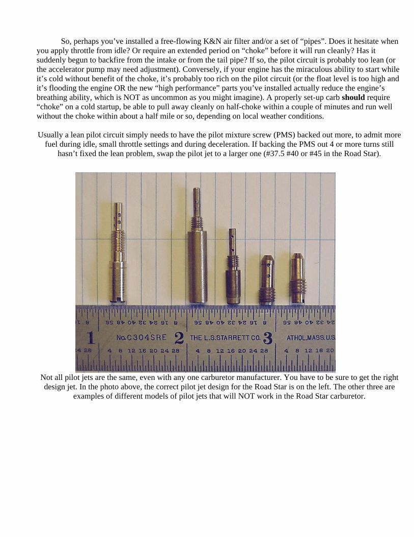
So, perhaps you’ve installed a free-flowing K&N air filter and/or a set of “pipes”. Does it hesitate when you apply throttle from idle? Or require an extended period on “choke” before it will run cleanly? Has it suddenly begun to backfire from the intake or from the tail pipe? If so, the pilot circuit is probably too lean (or the accelerator pump may need adjustment). Conversely, if your engine has the miraculous ability to start while it’s cold without benefit of the choke, it’s probably too rich on the pilot circuit (or the float level is too high and it’s flooding the engine OR the new “high performance” parts you’ve installed actually reduce the engine’s breathing ability, which is NOT as uncommon as you might imagine). A properly set-up carb should require “choke” on a cold startup, be able to pull away cleanly on half-choke within a couple of minutes and run well without the choke within about a half mile or so, depending on local weather conditions. Usually a lean pilot circuit simply needs to have the pilot mixture screw (PMS) backed out more, to admit more
fuel during idle, small throttle settings and during deceleration. If backing the PMS out 4 or more turns still hasn’t fixed the lean problem, swap the pilot jet to a larger one (#37.5 #40 or #45 in the Road Star).
Not all pilot jets are the same, even with any one carburetor manufacturer. You have to be sure to get the right design jet. In the photo above, the correct pilot jet design for the Road Star is on the left. The other three are
examples of different models of pilot jets that will NOT work in the Road Star carburetor.

Changing your pilot jet to a bigger one (it’ll be the same physical size, but have a bigger orifice) allows a greater potential fuel delivery from the pilot circuit, but it doesn’t actually richen the mixture most of time. That’s because the PMS is still the primary fuel controller at idle and small throttle settings. Its orifice, just downstream of the throttle plate, is normally restricted to something less than that of the pilot jet. Think of a garden hose with an open end. At any given pressure, the maximum flow is limited by the size of the hose’s inside diameter. Adding an adjustable nozzle on the end of the hose will allow adjustment of the flow to any amount less than the hose’s maximum capability. Even if the nozzle can be opened up to something larger than the hose ID, the flow is still limited to what the bare hose can deliver. In this analogy the hose ID correlates to the pilot jet orifice and the nozzle is the pilot mixture screw. The only significant difference between the hose analogy and your pilot system is that, at any given PMS setting, swapping to a larger pilot jet can deliver more fuel than the smaller one during periods of VERY high vacuum (like deceleration at road speeds). That’s because, while the PMS normally restricts fuel flow to something less than the pilot jet’s maximum flow, the especially powerful intake vacuum which exists during closed-throttle deceleration can overcome the restriction of the PMS enough to make the pilot jet opening the ultimate fuel metering devise. So, if it starts on choke, pulls away on partial choke in a minute or so, runs well without the choke a mile down the road, but backfires from the exhaust during decel, you may need to install a bigger pilot jet. First you want to be sure that simply backing the PMS out a bit more doesn’t fix the backfiring. If adjusting the PMS doesn’t fix it, installing a bigger pilot jet often does. Then you may need to reset the PMS to a slightly lower setting to bring the idle mixture back to where it was with the original pilot jet. The needle’s setting is both straightforward and potentially time consuming. Most jet kits come with instructions giving an initial set-up. Pay close attention to the order of assembly of the OEM setup and the assembly instructions that came with the jet kit. The placement of washers or plastic shims above or below the E-clip has significant effects on jetting by affecting the needle’s height relative to the needle jet. Be careful with the slide diaphragm. It is thin rubber and can be easily damaged. It may stick in the groove around the carb top, so coax it out with care. If you tear it or put a hole in it, the slide/diaphragm assembly will have to be replaced. The needle is held under a plastic retainer in the bottom of the slide. I suggest that you use a set of “duck bill” pliers to pull the retainer out. Be sure to pull it straight out; don’t wiggle it side-to-side. That can break the tabs in the bottom of the slide and then you’ll have to buy a new one. I like to lube the little o-ring on the plastic retainer with a thin coat of silicone grease, so it comes out easier thereafter. The kit manufacturer should tell you what grove to put the E-clip into (depending on the instructions that came with the jet kit, you’ll be counting the clip grooves from the fine tip or the fat end of the needle) and on which side of the e-clip to put the original and/or kit-supplied washers. Ultimately, you may need to vary from the recommended initial setup after some experimentation on the road, but start with the recommended settings. Be careful to reinstall the slide diaphragm so that its outer edge fits in the groove around the top of the carb. If the diaphragm is damaged or fails to achieve a good seal in the carb top, the slide will not react properly to throttle input. A lean needle setting will give less than optimum acceleration, may result in surging during steady cruise and will probably give poor gas mileage. Too rich will tend to give even worse mileage and, in extremely rich running, may foul spark plugs while yielding weak performance. Remember, the pilot circuit is a big factor at small throttle openings, so while cruising at 60 MPH in top gear (you aren’t opening the throttle much at such times), the pilot circuit is still effective. The best method to determine the optimum needle setup is through experimentation. After riding the bike with the kit-suggested setup, try lowering the needle a notch (raise the clip to the next groove up) and ride it again. Is it stronger? Weaker? Does it surge (or feel as if it’s just about to need to be switched to the reserve tank, before the engine dies) at steady throttle? Now try raising the needle
from the initial setup and note the changes. You’re looking for the setting that’s just a bit richer than the lean setting that caused it to run poorly (surging at steady throttle, hesitation, etc.). With the right needle placement, it should run smooth, respond well, accelerate strong and give good mileage. Most kits give several main jets, so you can go leaner or richer than the baseline recommendation, as needed. Again, start with the suggested jet and swap it from there as subsequent testing suggests. Essentially, the main jet is to the main system as the pilot jet is to its system, meaning that it limits the maximum fuel that the engine can get at wide open throttle, while the needle regulates fuel delivery at settings less than WFO. For that reason and especially with big cruisers like the Road Star, the main jet is the least critical part of the jetting to get absolutely perfect (unless you’re running at WFO a lot! In which case, you probably should be worried more about being hauled away in a squad car or ambulance, than with the jetting). Contrary to popular belief, many modern bikes actually come from the factory with a fairly rich main jet, in an effort to compensate for a lean needle design. So, depending on the intake and exhaust alterations, you may not need to go much larger than the stock main jet, if at all. Sometimes a main jet a bit smaller than the stocker is what it needs and that’s why jet kits often come with one or two main jet sizes smaller than the OEM part. Determining the best setup on the main jet is simply a matter of determining what size jet gives the highest speed at WFO. Only experimentation will do that. Assuming you can find a lonely stretch of straight road, you just experiment with different main jets until you find the one that nets you the highest top speed. With the Road Star, top speed will be well under maximum-safe RPMs for the engine simply because the gearing is so tall that only a radically modified engine will be able to reach the rev limit in top gear (read: nitrous oxide and/or supercharging). So the main jet selection process is simply a matter of finding the jet that makes the most horsepower, while struggling against aerodynamic and mechanical drag. Of course that scenario does have its obvious issues to contend with and that’s why dynamometers can be so useful. Or you can stop loosing sleep on whether a 172.5 main jet or a 175 is best. If the slightly bigger jet netted you one additional MPH in top gear, the engine wouldn’t have suffered from running on the 172.5 few riders would miss the extra MPH. Neither will affect your mileage with normal riding because until the throttle is pinned, the pilot circuit and needle are doing the fine metering of the fuel mixture.
It also bears mentioning that fuel level in the float bowl is a factor in how your carb works. With virtually all modern carbs, the fuel should be even with, or slightly below the gasket mating surface between float bowl and carb body. A couple millimeters below that gasket surface is usually OK, but the fuel level should never be above it. A fuel level which is too high can cause rich running (usually at all throttle settings) that will drive you crazy trying to fix with conventional jetting. If the float doesn’t shut off fuel feed to the carb before it hits the top of the float chamber, gas can overflow into the engine intake or spill into the air cleaner and then onto the engine or ground I(depending on which way is downhill from the needle jet). The potential dangers are obvious. Gas flowing onto the ground or hot exhaust can catch fire. Gas flowing into the intake tract can simply flood the engine or fill a cylinder and result in a broken piston when you hit the starter button. A maladjusted float, damaged float valve, dirt or other “crud” in the carb can cause the float to fail to shut the gas off at the proper level. When in doubt, drop the float bowl and look for foreign matter or “varnish” from old gas that went stale in the carb, clean it out and recheck the float level.
Some basic rules and symptoms that indicate a need for jetting changes can be distilled down to this:
1. Do ONE change to the jetting at a time! As an example; you suspect that your engine is
running too rich, giving lousy gas mileage. So you figure that some leaning of the mixture is called for and you want to save some time, so you screw the PMS in a ½ turn and lower the needle one clip-groove. If the engine now suffers from a lean stumble, is it because the needle is too low or the pilot circuit is too lean? Had you only adjusted one circuit at a time and then tested

it, you’d know if the change was beneficial or not. If the change caused a problem, or failed to improve on an issue, it can be reversed and you’ll know to try a different tactic.
2. If the engine is slow to warm-up, requiring extended time on the “choke” before it’ll run well, the pilot circuit is probably too lean. An excessively lean pilot circuit can also cause hesitation upon opening the throttle from idle, but if it’s not exhibiting slow warm-up, then the problem is probably a lean needle setting.
3. If the engine will start while cold without the choke, the float level may be excessively high, the float valve may not be closing due to something causing it to “hang” open or the pilot system is just set-up too rich. Usually it’s just a matter of leaning out the PMS, but if the carb is leaking gas, the problem is float adjustment or a problem with the float valve.
4. Once warmed up, if it smells of raw gas at idle, then the pilot circuit is too rich or the float level is too high. If screwing the PMS in doesn’t cure the problem, check the float level.
5. If the engine hesitates when you apply the throttle and then catches itself and responds normally, it’s a sign of a momentary lean condition. Assuming the pilot circuit is set-up well, then raising the needle a bit is the most common cure. But the problem may be caused by a too lean OR too rich accelerator pump setting. Too little fuel from the accelerator pump will allow it to suffer from a lean stumble, but then it’ll usually run well immediately after the hesitation. Too much fuel from the accel-pump can cause a misfire as the combustion chamber becomes momentarily saturated with fuel, but that’s usually accompanied by a BIG puff of black smoke from the tail pipe, so the diagnosis for an excessive dose of gas from accelerator pump is pretty obvious.
In this photo, you can see the two adjustment screws that control the accelerator pump. The upper screw
adjusts the onset of the accelerator pump squirt. The lower screw adjusts the ending of the squirt. Use the upper screw to adjust the pump to begin sending the gas into the carb as soon as the throttle plate begins to move. Then, with the lower screw, limit the duration of the squirt to only what the engine
needs to respond well to throttle input and no more.
6. An occasional intake backfire isn’t uncommon in a big, slow spinning engine like the Road Star. Even its fuel injected brothers, the Warrior and Roadliner, are subject to the occasional intake

“cough”. But if it’s frequent and/or robust enough to stall the engine, there is a problem that needs to be addressed. Intake backfiring is usually caused by a short-term lean condition. A lean mixture of gas & air burns slower than a correct or too-rich one. Sometimes it burns so slowly that combustion lasts through the exhaust stroke, right up to the time when the intake valve begins to open. When that happens, the rapidly expanding gases can blast up the intake tract and the result is a “cough” that may be little more than an occasional annoyance or one powerful enough to stall the engine. The fix may be a combination of raising the needle, richening the pilot system and/or the accelerator pump. Which system should you try first? Well, if it usually starts well on choke and warms up quickly, the pilot circuit probably isn’t the problem. If it’s not hesitating when the throttle is opened, gets good mileage and doesn’t surge at steady highway speeds, the needle is probably not too lean. Keep in mind that the engine would tend to suffer a momentary lean condition whenever you open the throttle from idle or small throttle settings, but the accelerator pump is there to keep that from happening. If intake backfiring is VERY frequent and/or powerful enough to stall the engine, it may be a sign that the intake valves are sticking in their guides. In that case, no amount of jetting will cure the problem. The heads may need to be removed, to ream the valve guides and polish the valve stems.
7. Even if the engine suffers infrequent intake backfiring, over time, it may cause havoc with the slide. The fire racing up the intake tract is very short lived, but the slide is made of hard plastic and it can be burned and have carbon buildup on its inboard surface. In the photo below, you can see the effects of intake backfiring, as it forms a rounded, rough surface on the slide, conforming to the shape of the carb’s bore. The buildup can be thick and course enough to cause the slide to stick in the carburetor and THAT can cause the engine to hesitate or even refuse to accelerate at all past some throttle settings. It may pull away and accelerate normally, but then suddenly refuse to accelerate past some higher RPMs, as intake air velocity forces the slide harder against the carb body, adding to the friction of the carbon buildup against the adjacent aluminum. The carbonization will form a circular shape on the lower portion of the slide, extending onto the “wings on its side. If your motorcycle has been jetted properly and running well for some time, but then suddenly exhibits such symptoms, the cause may be a burned slide (or a damaged diaphragm). The actual damage to the slide is minimal and can be easily polished away with a fine Scotchbrite pad. I don’t recommend using sandpaper because you’re more likely to remove too much material from the slide. Clean the slide afterwards with some Gummout and a paper towel.


Be sure the outer edge of the diaphragm fit into the round groove in the carb top, as it does in the above photo. If the edge does not have a good seal between the carb body and the plastic cover or if it is damaged, the slide
will not rise properly as the throttle is opened.
In summation…
There are other things that can cause the same symptoms as running too lean. Intake leaks between the carb and the engine can introduce enough air to cause a lean condition in a setup that would otherwise be fine. Extra air getting past the intake manifold at the heads or where the carb attaches to the manifold is usually too little to effect running at half-throttle or above, but it play havoc at idle or small throttle settings. Exhaust leaks at the header-to-head mounts can cause exhaust backfiring, by introducing enough air into the pipe to ignite unburned gas that would otherwise leave as unburned dinosaurs. Even the emission system, commonly called the Exhaust Air Induction System (AIS), can malfunction and introduce air into the exhaust that can cause backfiring. If the accelerator pump is delivering too much fuel or delivering it too late, it can cause intake backfiring as well, by loading the exhaust system with unburned gas, which gets ignited with additional hot gases coming from the engine. The float level can be too high or too low and that may affect any, or all, jetting parameters. A high fuel level richens the mixture and a low level can lean it. When conventional jetting seems to have none of the expected results, measuring float level may tell the tale. If conventional adjustments to the jetting don’t result in improved performance and rideability, check for intake and/or exhaust leaks, adjustments to the accelerator pump, and/or float level depending on the prevailing symptoms. If you’re careful not to knock the float out of adjustment while swapping jets (AND assuming the factory set it right in the first place), you shouldn’t have to alter the float adjustment.
Okay, so most of this has been about the modern CV carburetors that the factories use to give good power, good economy and to meet emissions regulations (when they haven’t already resorted to superior fuel injection). How about the so-called “race carbs” and the other designs that look like big lawnmower carbs? All the same principles apply, but they either use a “butterfly valve” in place of both the CV’s throttle plate and slide (like S&S carbs) or they just use a manually operated slide as the throttle (like the Mukuni HSR series and Edelbrock). The reason why such designs aren’t used on engines that have to meet tough emission standards is that they lack the CV carb’s (limited-) ability to compensate for atmospheric changes and they allow you to send fuel to the engine with every movement of your wrist, without regard to whether or not the engine has a use for it OR if can even burn it. With the CV carb, you control the airflow through carb with your right fist and the carburetor meters out fuel according to airflow and pressure changes in the carb’s bore, while keeping air velocity (and fuel atomization) reasonably consistent. So the CV carb does a better job of dispensing gas closer to what will burn efficiently (assuming the jetting is properly sorted out). The CV carb even compensates for changes in air pressure and altitude changes, to a limited degree. The slide throttle or butterfly throttle carbs do a better job of feeding the engine lots of (almost-) unrestricted air and that’s better for making maximum power at big throttle settings. But because air velocity through a non-CV carb varies more, they don’t offer the street-civility of the CV carb and the CV carb may actually make more horsepower than the “high performance” carbs at low to mid-RPMs. When you suddenly open the throttle on a CV carb, the slide and needle rise in accordance with the engine’s ability to gain RPMs and demand more air. With a non-CV carb, the right grip opens the butterfly or raises the slide whether or not the engine can use that much air at any given engine speed. But with proper tuning, carburetors like the Mikuni HSR series can net an appreciable gain in performance that many riders enjoy (even if it still drops MPG a little) and with a little thought and good throttle control, driveability can be as good as a CV carb. The race carburetors just don’t tolerate a sloppy throttle hand as well as the CV carb does.

Installing a carb that’s too big may cost you some low RPM performance and street civility too. Whatever the type of carburetor, as carb size goes up, so does the potential for higher maximum power at peak RPMs, simply because it can deliver more air and fuel to the engine. But a bigger carb tends to deliver more air at lower velocities at any given throttle setting. Slower moving air doesn’t do as good a job of filling the cylinders at low RPMs and fuel atomization may degrade into a wet mixture. That’s why motorcycle manufacturers often install smaller diameter carbs (or throttle bodies) on engines that have been taken from sportbike use and placed into service on lower revving standard models, tourers, and cruisers. When absolute maximum power isn’t the most important goal, then tune for civility and a broader range of useability and that often means using a carb that’s not the biggest available.
When engine displacement and/or RPMs go up, a bigger carb may be called for, simply because more
displacement may demand more fuel and air. Add in “hot” camshafts which can give the slide in a CV carb fits and sometimes a modified engine needs a different carburetor. Long valve timing, resulting in a lot of intake/exhaust overlap and/or fast opening and closing valves can cause harsh intake pulsing which can be troublesome to the CV carb. But those cases are the exception, rather than the rule. A 108 cubic inch Road Star, with 10.5:1 compression can run exceptionally well with the OEM 40mm CV carb, as long as it’s properly set-up. It’ll gain a few peak HP with a Mikuni HSR-42 carb, but driveability at less than full throttle may be better with the CV unit. The HSR-42 will also probably make a few less peak HP than the bigger HSR-45, but it will probably make more torque and horsepower at low to middle RPMs.
A word on other tools and procedures to help in determining the optimum jetting.
Dynamometers can be an asset in finding a good setup quickly. They can save you the time it takes to
suit up and go for multiple test rides while searching for the best jetting. And you can avoid potential trouble with local law enforcement as you search for the main jet that yields best top speed in 4th or 5th gear. By doing some experimentation with the jetting, while monitoring power production throughout the RPM range (and usually while also monitoring exhaust gases), a “dyno” can find the best setup very quickly. Sometimes the dyno will get your jetting very close, BUT not perfect, with the lingering need to check final results on the road. That’s because the dyno can’t mimic real road conditions. The way you ride, the flow of air past the intake and actual atmospheric conditions may dictate some final jetting adjustments. Thoroughly experienced tuners, armed with a modern dynamometer, often know the “tricks” to nail the jetting perfectly, with no need for additional tweaks by the owner. And sometimes a good tuner and his “carefully calibrated bum” can often do as well, or better, than a dyno and a team of technicians.
“Reading” spark plugs to determine the jetting on a street bike, while running modern, lead-free gas, is of little use, if any. Racers do it while running consistently superior gasoline of known qualities and they can get very good results. In fact, tuners of two stroke race engines go a step further by reading the deposits on the piston tops. Any time you examine your spark plug deposits, most what you’ll see are the results of combustion that existed at the moment the engine was last shut down. If you rode the bike, pulled into your garage in a normal manner, let it drop to idle and then turned off the ignition, the plugs will show the result of combustion at idle just before you turned the key off, NOT how lean or rich the main jet or needle setup are running while going down the highway. Reading the spark plugs to determine if the main jet is correct requires that you run the engine at WFO and then simultaneously kill the ignition while pulling in the clutch and closing the throttle. That way the spark plugs will show the results of combustion while the engine was running on the main jet. It’s called a “plug chop” and it’s not a trivial way to sort out the jetting on the street. Now add to that the dubious quality of modern, “pump gas”, which can give all sorts of doubtful deposits on the spark plugs and you’ve got little reason to waste your time with such folly. “Reading” the color of the tail pipe is just as unreliable and for most of the same reasons. Do you doubt that? Check out the spark plugs and/or tail pipe of any modern, emissions legal automobile. You know it’s not running too rich or excessively lean because it runs good, gets

good mileage and the emissions equipment insures it’s not polluting the environment. So why aren’t the spark plugs or tail pipe running a nice tan-to-light gray? It’s because modern, lead free gas (often with an added cocktail of emissions reducing chemicals required by federal and/or local regulations) doesn’t leave reliable telltale deposits that look like they did when we were burning the leaded gas of the 1970s. Bottom line: find the jetting that makes it run well and give good mileage and don’t worry about what color the deposits on the spark plugs or tail pipe are. Granted, if the spark plugs are so heavily fouled with deposits that the engine has been misfiring, that’s an indication that something needs tweaking. But studying the spark plugs or tail pipe won’t help much in determining the best course of action.