CAR - Projects Org « Complete IT and Non IT Projects · Web viewThis means that numeric data...
166
PAYROLL MANAGMENT SYSTEM
Transcript of CAR - Projects Org « Complete IT and Non IT Projects · Web viewThis means that numeric data...
PAYROLL MANAGMENT
SYSTEM

SUBMITTED BY:
ACKNOWLEDGEMENT
With Candor and Pleasure I take opportunity to express my sincere thanks and obligation to my esteemed guide . It is because of his able and mature guidance and co-operation without which it would not have been possible for me to complete my project.
It is my pleasant duty to thank all the staff member of the computer center who never hesitated me from time during the project.
Finally, I gratefully acknowledge the support, encouragement & patience of my family, And as always, nothing in my life would be possible without God, Thank You!

1. Preface
2. System Study2.1. Introduction2.2. Feasibility Study2.3. System Overview
3. System Analysis3.1. Importance of Computerized
PAYROLL MANAGMENT System3.2. About the Project3.3. Functional Requirements
4. System Design4.1. System Development Cycle4.2. Context Level DFD4.3. DFD for Car Renting System4.4. Search Process
TABLE OF CONTENT
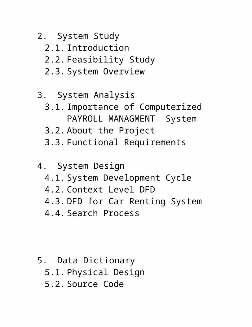
5. Data Dictionary5.1. Physical Design5.2. Source Code
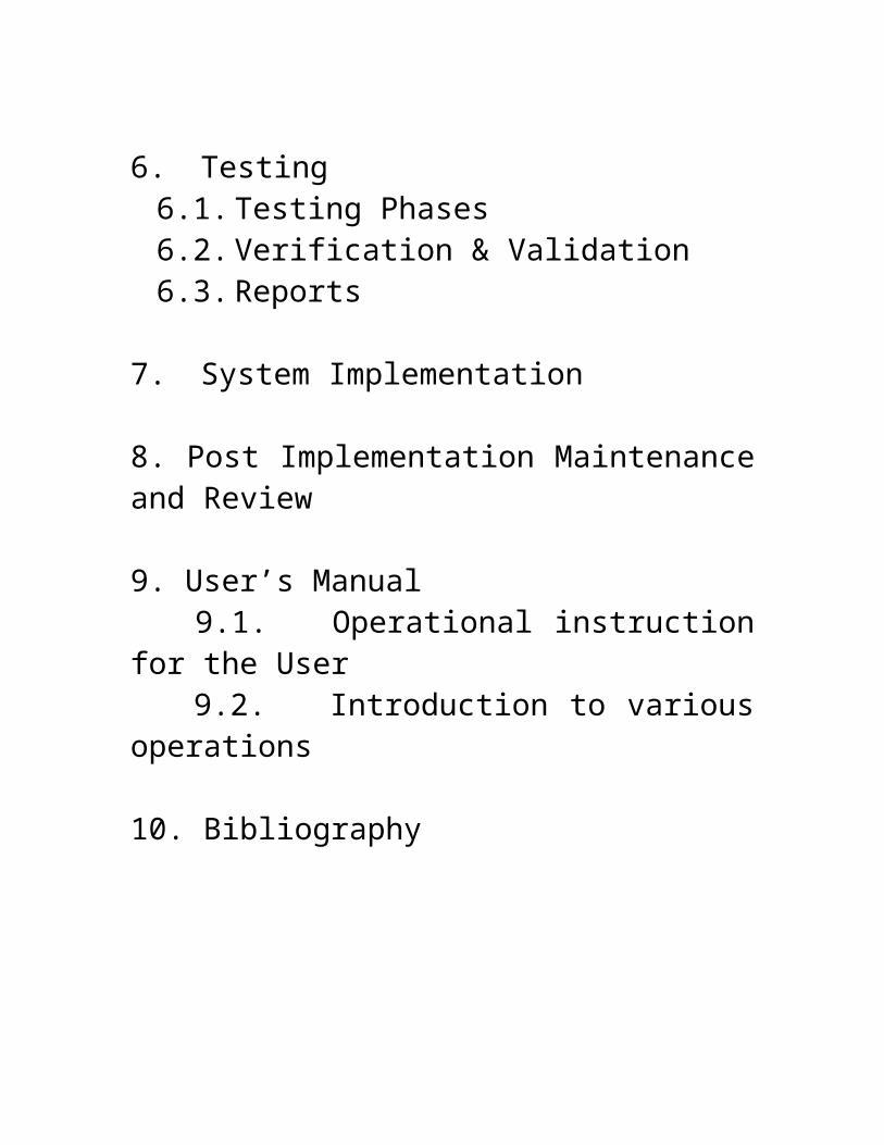
6. Testing6.1. Testing Phases6.2. Verification & Validation6.3. Reports
7. System Implementation
8. Post Implementation Maintenance and Review
9. User’s Manual 9.1. Operational instruction for the User 9.2. Introduction to various operations
10. Bibliography
PROBLEM DEFINITION
1.1 INTRODUCTION TO THE PROBLEM:
This is a Project work undertaken in context of partial fulfillment of the BIT. Since PAYROLL is associated with the lives of common people and their day to day routines so I decided to work on this project. The manual handling of the record is time consuming and highly prone to error. The user can inputs codes of Employee he wants to see Pay Slip. The activities like see Employee Record , add Record, modify records, delete Record and finally receiving Pay Slip can be performed easily. .
I found two main key-points to design and programmed my project using TURBO C++ and its FILES facility as database storage. First, Because TURBO C++ compiler has the ability to debug the project at run time and gives appropriate error messages if it found in the project at run time. Its help is too enough to learn and study any function of a particular header file using the keyboard Keys (Ctrl + F1) to keep the cursor on that particular function. Second.I have tried my best to make the complicated process of PAYROLL MANAGEMENT System as simple as possible using Structured & Modular technique & Menu oriented interface. I have tried to design the software in such a way that user may not have any difficulty in using this package & further expansion is possible without much effort. Even though I cannot claim that this work to be entirely exhaustive, the main purpose of my exercise is perform each PayRoll’s activity in computerized way rather than manually which is time consuming.

I am confident that this software package can be readily used by non-programming personal avoiding human handled chance of error.
1.2 NEED:
I have designed the given proposed system in the C++ to automate the process of Payroll system.
The complete set of rules & procedures related to PayRoll and generating report is called “PAYROLL MANAGEMENT SYSTEM”. My project gives a brief idea regarding automated Payroll activities.
The following steps that gives the detailed information of the need of proposed system are:
Performance: During past several decades, the Payroll is supposed to maintain manual handling of all the Payroll activities. The manual handling of the record is time consuming and highly prone to error. To improve the performance of the payroll system, the computerized payroll system is to be undertaken. The computerized project is fully computerized and user friendly even that any of the members can see the report and status of the pay.
Efficiency: The basic need of the project is accuracy and efficiency . The project should be efficient so that whenever a Employee is added,add his Record , delete his record, display and generate his payslip.
Control: The complete control of the project is under the hands of authorized person who has the password to access this project and illegal access is not supposed to deal with. All the control is under the administrator and the other members have the rights to just see the records not to change any transaction or entry.
Security: Security is the main criteria for the proposed system. Since illegal access may corrupt the database. So security has to be given in this project.
Software: Software includes the platform where the Payroll project is being prepared. I have done my project using DOS based Compiler TURBO C++ platform and the database is the FILE HANDLING MECHANISM OF TURBO C++. But it is not necessary that we have to first install Turbo C++ to run this project.

OBJECTIVEDuring the past several decades personnel function has been transformed from a relatively obscure record keeping staff to central and top level management function. There are many factors that have influenced this transformation like technological advances, professionalism, and general recognition of human beings as most important resources.
A computer based management system is designed to handle all the primary information required to calculate monthly statements of Employees Record which include monthly statement of any month. Separate database is maintained to handle all the details required for the correct statement calculation and generation.
This project intends to introduce more user friendliness in the various activities such as record updation, maintenance, and searching. The searching of record has been made quite simple as all the details of the Employee can be obtained by simply keying in the identification of that Employee. Similarly, record maintenance and updation can also be accomplished by using the identification of Employee with all the details being automatically generated. These details are also being promptly automatically updated in the master file thus keeping the record absolutely up-to-date.
The entire information has maintained in the database or Files and whoever wants to retrieve can’t retrieve, only authorization user
can retrieve the necessary information which can be easily be accessible from the file.
The main objective of the entire activity is to automate the process of day to day activities of pay.

FEASIBILITY STUDY
The feasibility study proposes one or more conceptual solution to the problem set of the project. In fact, it is an evaluation of whether it is worthwhile to proceed with project or not.
Feasibility analysis usually considers a number of project alternatives, one that is chosen as the most satisfactory solution. These alternatives also need to be evaluated in a broad way without committing too many resources. Various steps involved in feasibility analysis are:
1. To propose a set of solution that can realize the project goal. These solutions are usually descriptions of what the new system should look like.
2. Evaluation of feasibility of such solutions. Such evaluation often indicates shortcomings in the initial goals. This step is repeated as the goals are adjusted and the alternative solutions are evaluated.
Four primary areas of interest in feasibility study are:
Economic Feasibility: An evaluation of development cost weighed against the ultimate income of benefit derived from the development system of product. In economic feasibility, cost benefit analysis is done in which expected cost and benefits are evaluated.
COST AND BENEFIT ANALYSIS

Developing an IT application is an investment. Since after developing that application it provides the organization with profits. Profits can be monetary or in the form of an improved working environment. However, it carries risks, because in some cases an estimate can be wrong. And the project might not actually turn out to be beneficial.
Cost benefit analysis helps to give management a picture of the cost, benefits and risks. It usually involves comparing alternate investments.
Cost benefit determines the benefits and savings that are expected from the system and compares them with the expected costs.
In performing cost and benefit analysis it is important to identify cost and benefits factors. Cost and benefits can be categorized into the following categories:
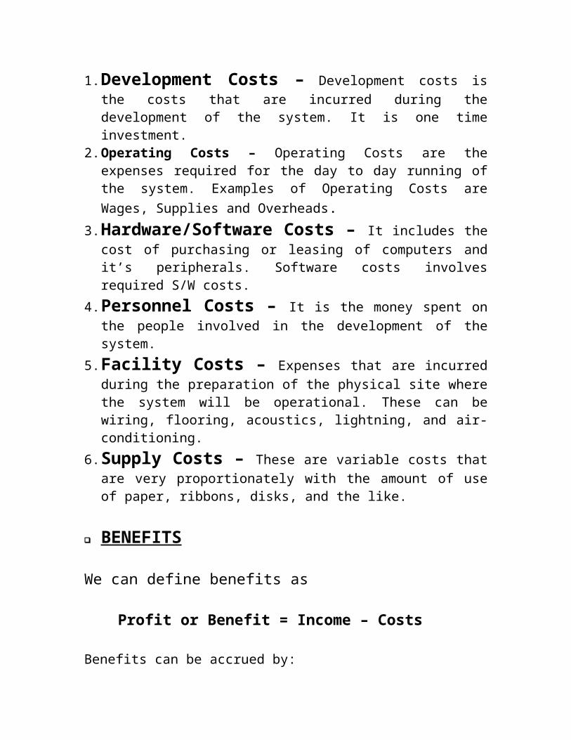
1. Development Costs – Development costs is the costs that are incurred during the development of the system. It is one time investment.
2. Operating Costs – Operating Costs are the expenses required for the day to day running of the system. Examples of Operating Costs are Wages, Supplies and Overheads.
3. Hardware/Software Costs – It includes the cost of purchasing or leasing of computers and it’s peripherals. Software costs involves required S/W costs.
4. Personnel Costs – It is the money spent on the people involved in the development of the system.
5. Facility Costs – Expenses that are incurred during the preparation of the physical site where the system will be operational. These can be wiring, flooring, acoustics, lightning, and air-conditioning.
6. Supply Costs – These are variable costs that are very proportionately with the amount of use of paper, ribbons, disks, and the like.

BENEFITS
We can define benefits as
Profit or Benefit = Income – Costs
Benefits can be accrued by:
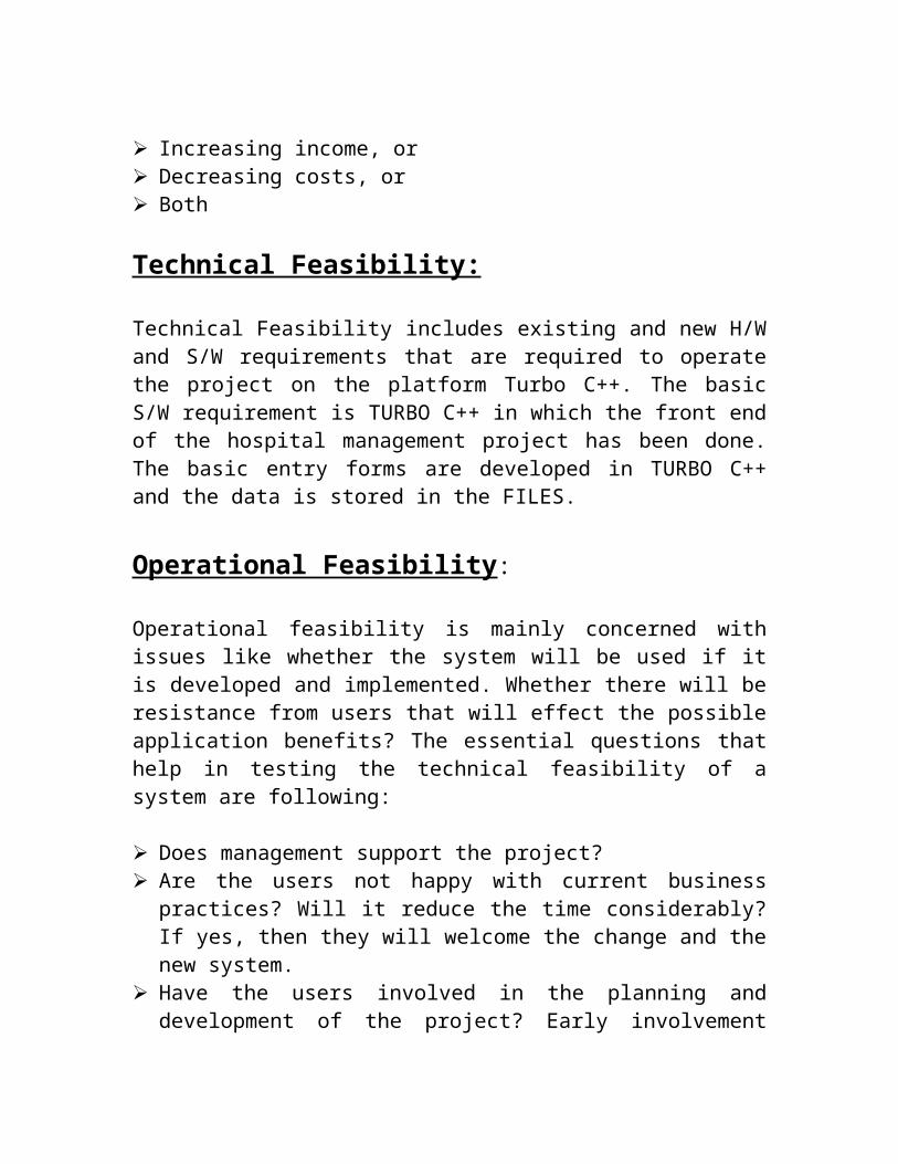
Increasing income, or Decreasing costs, or Both
Technical Feasibility:
Technical Feasibility includes existing and new H/W and S/W requirements that are required to operate the project on the platform Turbo C++. The basic S/W requirement is TURBO C++ in which the front end of the hospital management project has been done. The basic entry forms are developed in TURBO C++ and the data is stored in the FILES.
Operational Feasibility:
Operational feasibility is mainly concerned with issues like whether the system will be used if it is developed and implemented. Whether there will be resistance from users that will effect the possible application benefits? The essential questions that help in testing the technical feasibility of a system are following:
Does management support the project? Are the users not happy with current business practices? Will it reduce
the time considerably? If yes, then they will welcome the change and the new system.
Have the users involved in the planning and development of the project? Early involvement reduced the probability of resistance towards the new system.
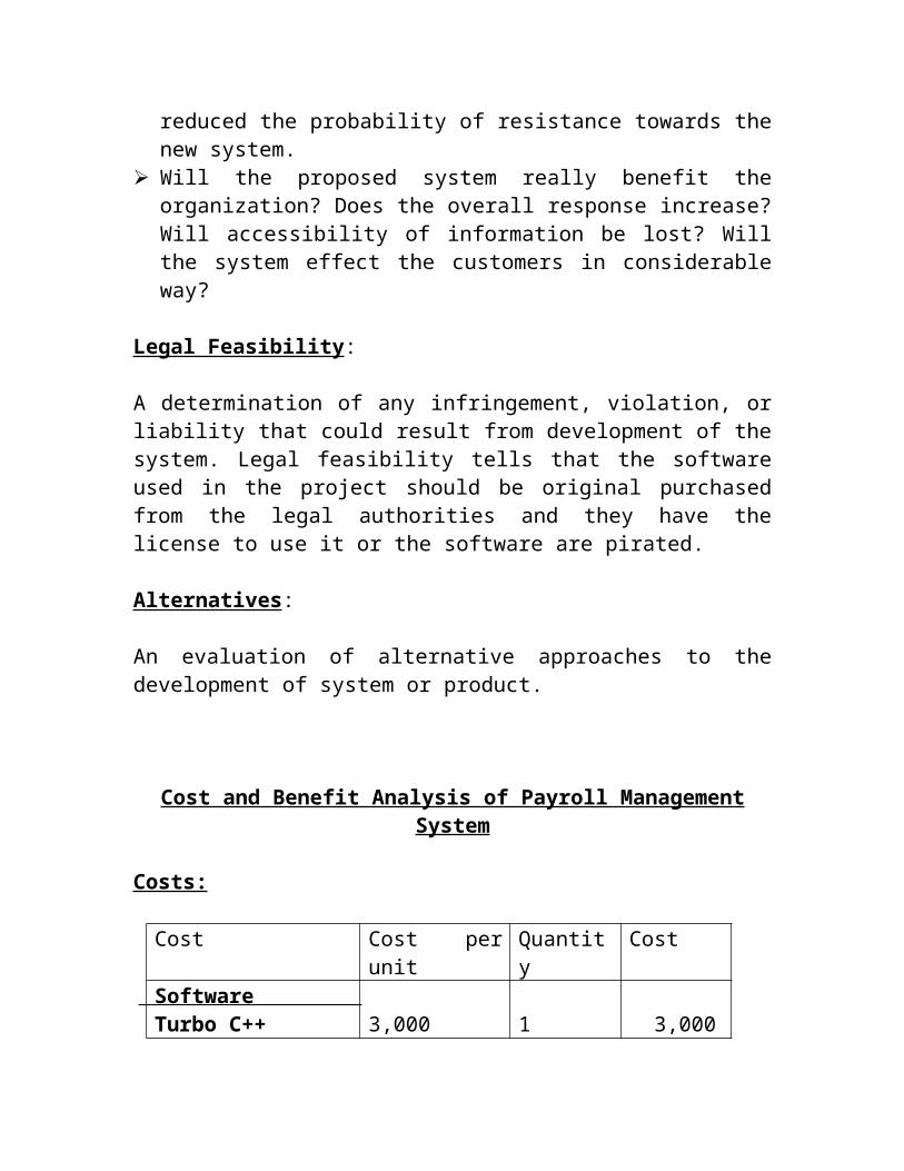
Will the proposed system really benefit the organization? Does the overall response increase? Will accessibility of information be lost? Will the system effect the customers in considerable way?
Legal Feasibility:
A determination of any infringement, violation, or liability that could result from development of the system. Legal feasibility tells that the software used in the project should be original purchased from the legal authorities and they have the license to use it or the software are pirated.
Alternatives:
An evaluation of alternative approaches to the development of system or product.
Cost and Benefit Analysis of Payroll Management System
Costs:
Cost Cost per unit Quantity CostSoftwareTurbo C++Windows NT ServerWindows 98Hardware
3,00030,00015,0004,000
1112
3,00030,00015,000 8,000
Central ComputerClient MachineDevelopment
100,00050,000
14
1,00,0002,00,000
AnalystDeveloperTrainingData EntryWarranty (1 month)
50,00020,00020,0005,0000
1211
50,00040,00020,000 5,000
Professional 20,000 1 20,000TOTAL COST 4,91,000
According to the Payroll System, Rs. 250 pay for a day of a single employee .
Expected increase in the number of Employee: 40 per month and number of customer for local is: 150 per day.Let the amount collected from operations in a month: 250,000 for a month.
Amount collected from the Employee when he returns car this year =12*(40 * (250 + 450) + 150 * 30 * 30 + 250000)=Rs. 49,56,000
For three years = 3 * 4956,000 = Rs. 1,48,68,000
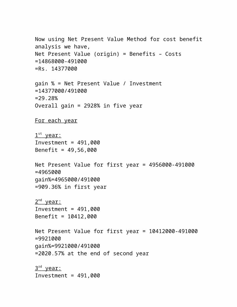
Now using Net Present Value Method for cost benefit analysis we have,Net Present Value (origin) = Benefits – Costs=14868000-491000=Rs. 14377000
gain % = Net Present Value / Investment=14377000/491000=29.28%Overall gain = 2928% in five year
For each year
1 st year: Investment = 491,000Benefit = 49,56,000
Net Present Value for first year = 4956000-491000=4965000gain%=4965000/491000=909.36% in first year
2 nd year: Investment = 491,000Benefit = 10412,000
Net Present Value for first year = 10412000-491000=9921000gain%=9921000/491000=2020.57% at the end of second year
3 rd year: Investment = 491,000Benefit = 15859000
Net Present Value for first year = 15859000-491000=15368000gain%=15368000/491000=3129.93% at the end of third year
From cost and benefit analysis we have found that the project is economically feasible since it is showing great gains (approx. above 3000%).
After economic feasibility, technical feasibility is done. In this, major issue is to see if the system is developed what is the likelihood that it’ll be implemented and put to operation? Will there be any resistance from its user?
It is clear that the new automated system will work more efficiently and faster. So the users will certainly accept it. Also they are being actively involved in the development of the new system. So our system is operationally feasible.
After the feasibility study has been done and it is found to be feasible, the management has approved this project.
FACT FINDING TECHNIQUES
The functioning of the system is to be understood by the system analyst to design the proposed system. Various methods are used for this and these are known as fact-finding techniques. The analyst needs to fully understand the current system.
The analyst needs data about the requirements and demands of the project undertaken and the techniques employed to gather this data are known as fact-finding techniques. Various kinds of techniques and the most popular among them are interviews, questionnaires, record views, case tools and also the personal observations made by the analyst himself.
Interviews
Interview is a very important data gathering technique as in this the analyst directly contacts system and the potential user of the proposed system.
One very essential aspect of conducting the interview is that the interviewer should first establish a rapport with the interviewee. It should also be taken into account that the interviewee may or may not be a technician and the analyst should prefer to use day to day language instead of jargon and technical terms.
The advantage of the interview is that the analyst has a free hand and the he can extract almost all the information from the concerned people but then as
it is a very time consuming method, he should also employ other means such as questionnaires, record reviews, etc. This may also help the analyst to verify and validate the information gained. Interviewing should be approached, as logically and from a general point of view the following guides can be very beneficial for a successful interview:1. Set the stage for the interview.2. Establish rapport; put the interview at ease.3. Phrase questions clearly and succinctly.4. Be a good listener; a void arguments.5. Evaluate the outcome of the interview.
The interviews are of the two types namely structured and unstructured.
I . Structured Interview
Structured interviews are those where the interviewee is asked a standard set of questions in a particular order. All interviews are asked the same set of questions. The questions are further divided into two kinds of formats for conducting this type if interview.
II. Unstructured Interview
answer format. This is of a much more flexible nature than the structured and The unstructured interviews are undertaken in a question-and-can be very rightly used to gather general in formation about the system.
Questionnaires:
Questionnaires are another way of information gathering where the potential users of the system are given questionnaires to be filled up and returned to the analyst.
Questionnaires are useful when the analyst need to gather information from a large number of people. It is not possible to interview each individual. Also if the time is very short, in that case also questionnaires are useful. If the analyst guarantees the anonymity of the respondent then the respondent answers the questionnaires very honestly and critically.

The analyst should sensibly design and frame questionnaires with clarity of it’s objective so as to do just to the cost incurred on their development and distribution.
Record Reviews
Records and reports are the collection of information and data accumulated over the time by the users about the system and it’s operations. This can also put light on the requirements of the system and the modifications it has undergone. Records and reports may have a limitation if they are not up-to-date or if some essential links are missing. All the changes, which the system suffers, may not be recorded. The analyst may scrutinize the records either at the beginning of his study which may give him a fair introduction about the system and will make him familiar with it or in the end which will provide the analyst with a comparison between what exactly is/was desired from the system and it’s current working.
On-Site Observation
On-site observations are one of the most effectively tools with the analyst where the analyst personally goes to the site and discovers the functioning of the system. As a observer, the analyst can gain first hand knowledge of the activities, operations, processes of the system on-site, hence here the role of an analyst is of an information seeker. This information is very meaningful as it is unbiased and has been directly taken by the analyst. This exposure also sheds some light on the actual happenings of the system as compared to what has already been documented, thus the analyst gets closer to system. This technique is also time-consuming and the analyst should not jump to conclusions or draw inferences from small samples of observation rather the analyst should be more.
ANALYST’S INTERVIEW WITH ADMINISTRATOR
Analyst: Hi, I have come to talk to you regarding the functioning of your payroll project.
Administrator: hello, do come in. I was expecting you.
Analyst: I’ll come straight to the point. Don’t hesitate, you can be as much open you want. There are no restrictions.
Administrator: I’ll give you my whole contribution.
Analyst: Tell me are you excited about the idea of having an automated system for your Payroll system?
Administrator: Yes, I do. Very much. After all it’s gonna reduce our loads of work.
Analyst: Will you elaborate on it?Administrator: Major problem is managing the record of the
Employee , Display the record, Delete the record . At the time of payroll, it becomes more difficult to handle the report of payslip.
Analyst: What do you think be ideal solution to this?Administrator: All the information of Employee should be put into
computer. It’ll be easy for us to check how many record are avilable or not available of employee.
Analyst: Could you explain how?Administrator: Look whenever a new Employee is come he/she is
allotted a any Id or Code and the is reserved for the till the employee gets leave his job.
Analyst: Do you have different Employee categories?Administrator: yes we have categorization for Employee .
Analyst: How do you categorize your Employee?Administrator: By ID no. and by name both.
Analyst: Do you have any other expectations or suggestion for the new system?
Administrator: It should be able to produce reports faster.

Analyst: Reports? I completely forgot about them. What reports you people produce presently?
Administrator: Well first is for Employee record another for Employee’s list .
Analyst: Do you have some format for them?Administrator: Yes we do have and we want that the same format be
used by the new system.
Analyst: Yes we’ll take care of that. Any other suggestions?Administrator: No. You have already covered all the fields.
Analyst: Thanks for your co-operation. It was nice talking to you.Administrator: My pleasure. Bye.
QUESTIONNAIRES FOR STAFFInstructions: Answer as specified by the format. Put NA for non-application situation.
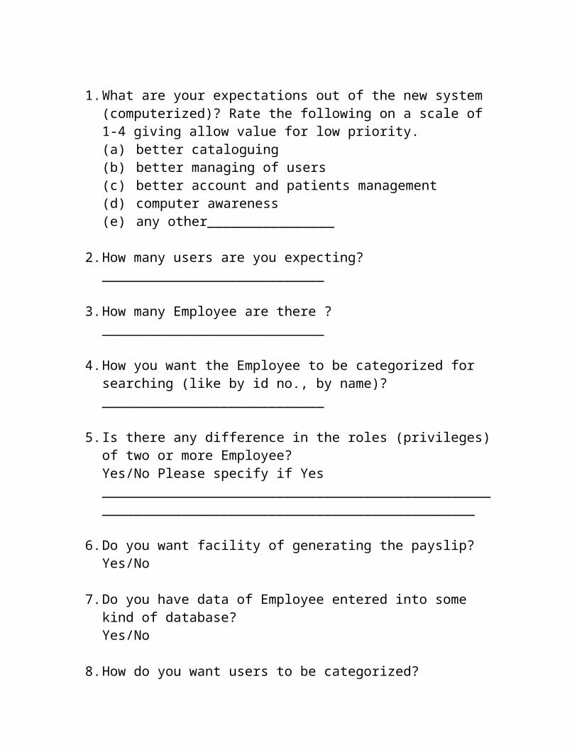
1. What are your expectations out of the new system (computerized)? Rate the following on a scale of 1-4 giving allow value for low priority.(a) better cataloguing(b) better managing of users(c) better account and patients management(d) computer awareness(e) any other________________
2. How many users are you expecting?____________________________
3. How many Employee are there ?____________________________
4. How you want the Employee to be categorized for searching (like by id no., by name)?____________________________

5. Is there any difference in the roles (privileges) of two or more Employee?Yes/No Please specify if Yes________________________________________________________________________________________________
6. Do you want facility of generating the payslip?Yes/No
7. Do you have data of Employee entered into some kind of database?Yes/No
8. How do you want users to be categorized?_______________________or_______________________
9. Would you like online registration for users rather than the printed form?Yes/No
10.Do you already have some existing categorization of Employee on the basis as specified in question 4 above?Yes/No
11.Any other specific suggestion/expectation out of the proposed system.____________________________________________________________________________________________________

SYSTEM OVERVIEWThe limited time and resources have restricted us to incorporate, in this project, only a main activities that are performed in a PAYROLL MANAGEMENT System, but utmost care has been taken to make the system efficient and user friendly. “PAYROLL MANAGEMENT System” has been designed to computerized the following functions that are performed by the system:
1. EMPLOYEES Detail Functions
a) Adding a New RECORDb) Modification to RECORD assigned
a) Admission of New EMPLOYEE .b) Deleting of EMPLOYEE record.
2. Report/Details Functions
a) Statement of Pay Detailsa.1) DA a.2) HR
b) Total number of EMPLOYEE. c) Individual EMPLOYEE Report .

IMPORTANCE OF COMPUTERIZED PAYROLL MANAGEMENT
SYSTEMThere are several attributes in which the computer based information works. Broadly the working of computer system is divided into two main groups:
Transaction System Decision Support System
Transaction System:
A transaction is a record of some well-defined single and usually small occurrence in a system. Transactions are input into the computer to update the database files. It checks the entering data for its accuracy. This means that numeric data appears in numeric field and character data in character field. Once all the checks are made, transaction is used to update the database. Transaction can be inputted in on-line mode or batch mode. In on-line mode, transactions are entered and updated into the
database almost instantaneously. In batch mode, transactions are collected into batches, which may be held for a while and inputted later.
Decision Support System:
It assists the user to make analytical decision. It shows the various data in organized way called analysis. This analysis can be made to syrdy preferences and help in making decisions. Computer system works out best with record maintenance. It will tell you which EMPLOYEE would get how much pending/reports statements. It will also help to search the information about a particular person by simply entering his telephone number.
User can store information as per requirement, which can be used for comparison with other reports.

FUNCTIONDETAILSThe basic objective of PAYROLL MANAGEMENT SYSTEM is to generalize and simplify the monthly or day to day activities of Payroll like Admission of New employee, payroll, payslip Assigning related to particular employee, Reports of Number of Employee and delete the employee record etc. which has to be performed repeatedly on regular basis. To provide efficient, fast, reliable and user-friendly system is the basic motto behind this exercise.
Let us now discuss how different functions handle the structure and data files:
1. Function ADD RECORD ( )
This is the function used to open a new record for a employee so that he/she can assign a separate Record. In that screen, the automatic EMPLOYEE number . After opening a new record for the employee, finally a CODE is assigned to a EMPLOYEE .
This function is used for employee in our company after entering his all personal details like Name, Address, Phone, Sex including date of joining , he have his own convence or Not and his salary.
2. Function EDIT( )
This function is used to delete the employee details from database. When the user inputs his code number, the same account number will be checked in the database, if the code number is matched in the database, then the employee record will be deleted from the database and transferred the record of the deleted employee to another table of database so that the Payroll Management has the record of deleted employee to fulfill his legal liabilities.
3. Function GENERATE_ PAYSLIP()
When any employee required his payslip, his/her bill is generated automatically by calculated salary, DA ,HRA etc. It also give its code and date of joining.
4. Function DISPLAY_RECORD()
This function is used to display all the transaction including the Employee name, address, phone, code number to him/her in the screen. This is a global report to display all the transaction records in the screen.
TESTINGStandard C and Pre-Standard C
1989 Standard C is widespread enough now that it is ok to use its features in new programs. There is one exception: do not ever use the "trigraph" feature of Standard C.
1999 Standard C is not widespread yet, so please do not require its features in programs. It is ok to use its features if they are present. However, it is easy to support pre-standard compilers in most programs, so if you know how to do that, feel free. If a program you are maintaining has such support, you should try to keep it working.
To support pre-standard C, instead of writing function definitions in standard prototype form,
intfoo (int x, int y)...

Write the definition in pre-standard style like this,
intfoo (x, y) int x, y;...
and use a separate declaration to specify the argument prototype:
int foo (int, int);
You need such a declaration anyway, in a header file, to get the benefit of prototypes in all the files where the function is called. And once you have the declaration, you normally lose nothing by writing the function definition in the pre-standard style. This technique does not work for integer types narrower than int. If you think of an argument as being of a type narrower than int, declare it as int instead.
There are a few special cases where this technique is hard to use. For example, if a function argument needs to hold the system type dev_t, you run into trouble, because dev_t is shorter than int on some machines; but you cannot use int instead, because dev_t is wider than int on some machines. There is no type you can safely use on all machines in a non-standard definition. The only way to support non-standard C and pass such an argument is to check the width of dev_t using Autoconf and choose the argument type accordingly. This may not be worth the trouble.
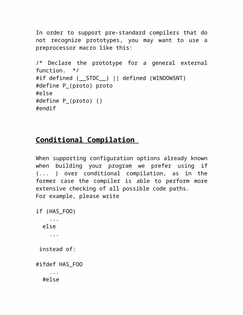
In order to support pre-standard compilers that do not recognize prototypes, you may want to use a preprocessor macro like this:
/* Declare the prototype for a general external function. */#if defined (__STDC__) || defined (WINDOWSNT)#define P_(proto) proto#else#define P_(proto) ()#endif
Conditional Compilation
When supporting configuration options already known when building your program we prefer using if (... ) over conditional compilation, as in the former case the compiler is able to perform more extensive checking of all possible code paths. For example, please write
if (HAS_FOO) ... else ...
instead of:
#ifdef HAS_FOO ... #else ... #endif
A modern compiler such as GCC will generate exactly the same code in both cases, and we have been using similar techniques with good success in several projects.
While this is not a silver bullet solving all portability problems, following this policy would have saved the GCC project alone many people hours if not days per year.
In the case of function-like macros like REVERSIBLE_CC_MODE in GCC which cannot be simply used in if( ...) statements, there is an easy workaround. Simply introduce another macro HAS_REVERSIBLE_CC_MODE as in the following example:
#ifdef REVERSIBLE_CC_MODE #define HAS_REVERSIBLE_CC_MODE 1

#else #define HAS_REVERSIBLE_CC_MODE 0 #endif
Formatting Error Messages
Error messages from compilers should look like this:
Source-file-name:lineno: message
If you want to mention the column number, use one of these formats:
Source-file-name:lineno:column: messageSource-file-name:lineno.column: message
Line numbers should start from 1 at the beginning of the file, and column numbers should start from 1 at the beginning of the line. (Both of these conventions are chosen for compatibility.) Calculate column numbers assuming that space and all ASCII printing characters have equal width and assuming tab stops every 8 columns.
In an interactive program (one that is reading commands from a terminal), it is better not to include the program name in an error message. The place to indicate which program is running is in the prompt or with the screen layout. (When the same program runs with input from a source other than a terminal, it is not interactive and would do best to print error messages using the non-interactive style.)
The string message should not begin with a capital letter when it follows a program name and/or file name. Also, it should not end with a period. Error messages from interactive programs, and other messages such as usage messages, should start with a capital letter. But they should not end with a period.

FUNCTIONAL REQUIREMENT
The platform is the hardware and software combination that the Client/Server runs on. While hardware systems vary widely in features and capabilities, certain common features are needed for the operating system software.
HARDWARE SPECIFICATIONS
Hardware is a set of physical components, which performs the functions of applying appropriate, predefined instructions. In other words, one can say that electronic and mechanical parts of computer constitute hardware.
This package is designed on a powerful programming language Visual Basic. It is a powerful Graphical User Interface. The backend is ORACLE, which is used to maintain database. It can run on almost all the popular microcomputers. The following are the minimum hardware specifications to run this package: -
Processors and memory

The best system to start with is one based on Pentium II with a minimum 32 MB of RAM. Adequate performance requires at least 64 MB of RAM. But for a database server at least 64 to 128 MB of RAM is required.
Video displaysEarlier, the IBM-compatible computers had a simple text-only monochrome for the video display. Now, they use the advanced high-resolution color displays. For Client/Server systems one should have VGA or better video display.
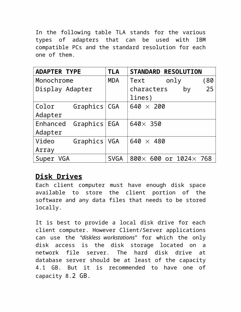
In the following table TLA stands for the various types of adapters that can be used with IBM compatible PCs and the standard resolution for each one of them.
ADAPTER TYPE TLA STANDARD RESOLUTIONMonochrome Display Adapter
MDA Text only (80 characters by 25 lines)
Color Graphics Adapter CGA 640 200Enhanced Graphics Adapter
EGA 640 350
Video Graphics Array VGA 640 480Super VGA SVGA 800 600 or 1024 768
Disk DrivesEach client computer must have enough disk space available to store the client portion of the software and any data files that needs to be stored locally.
It is best to provide a local disk drive for each client computer. However Client/Server applications can use the “diskless workstations” for which the only disk access is the disk storage located on a network file server. The hard disk drive at database server should be at least of the capacity 4.1 GB. But it is recommended to have one of capacity 8.2 GB.

MouseA mouse is a must for the client software running under Windows OS or any other graphical environment.
KeyboardEach client must have a 104 keys extended keyboard.
SOFTWARE REQUIREMENTS
The software is a set of procedures of coded information or a program which when fed into the computer hardware, enables the computer to perform the various tasks. Software is like a current inside the wire, which cannot be seen but its effect can be felt.
Application software : TURBO C++ [Dos Based]

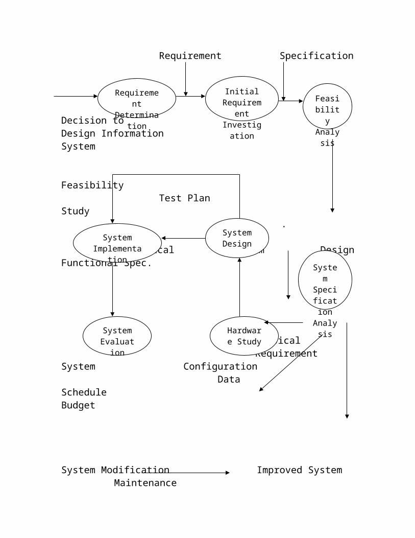
SYSTEM DEVELOPMENT LIFE CYCLE
User Revised Requirement Requirement Specification
Decision toDesign Information System
FeasibilityTest Plan Study
.
Logical System Design Functional Spec.
Requirement Determinatio
n
Initial Requirement Investigatio
n
Feasibility
Analysis
System Implementation
System Design
System Specific
ation Analysi
s
System Evaluation
Hardware Study

Physical Requirement
System Configuration Data
Schedule Budget
System Modification Improved System Maintenance
CONTEXT LEVEL DFDPAYROLLMANAGEMENT SYSTEM
EMPLOYEECODE
PAYROLL MANAGEMENT
SYSTEM

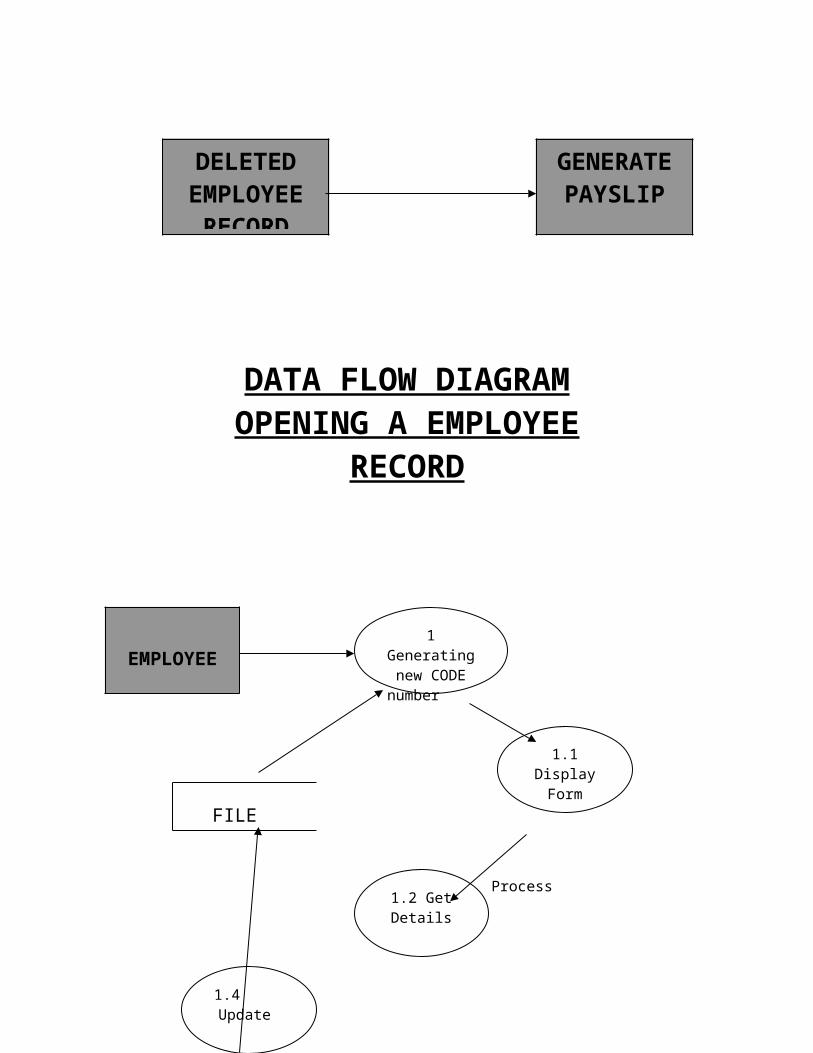
DATA FLOW DIAGRAMOPENING A EMPLOYEE
RECORD
FILE
DELETEDEMPLOYEE
RECORD
GENERATEPAYSLIP
Process
Update Table
EMPLOYEE1 Generating new CODE
number
1.1 Display Form
1.2 Get Details
1.4 Update
Employee Document
DATA FLOW DIAGRAMADMISSION OF A NEW EMPLOYEE
FILE
employee Details
Process
Update Table
EMPLOYEE1 Assigning a newcode
number
1.1 Display Form
1.2 Get Details
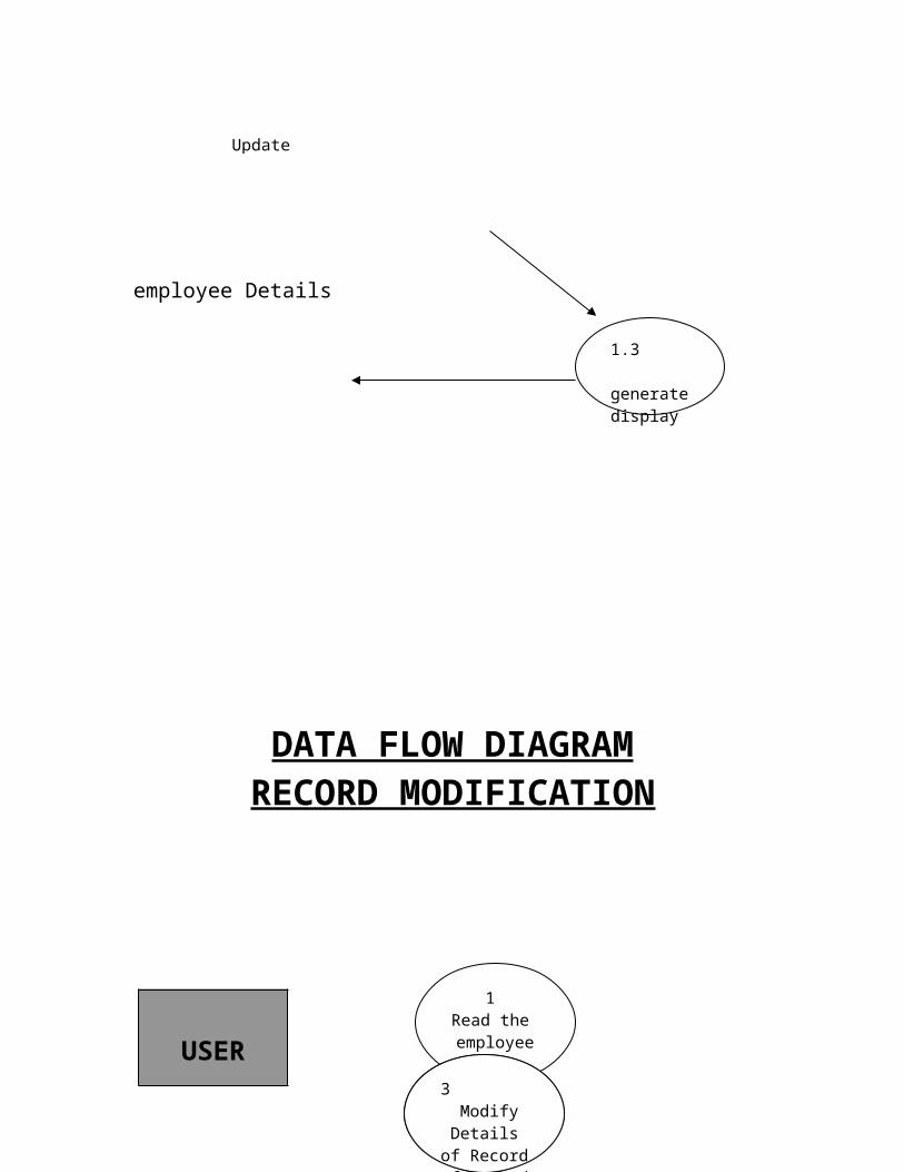
1.3 generate display
1.4 Update
1.3 Open new code

DATA FLOW DIAGRAMRECORD MODIFICATION
FILE
UpdateProcessing
Scan Record
USER
1 Read the employee
code
2 Show the Details of
Record
3 Modify
Details of Record
DATA FLOW DIAGRAMDELETE OF EMPLOYEE
FILE
Emploiyee Details
ProcessUpdate Table
EMPLOYEE1 Scan the
EMPLOYEE number
1.1 Display Form
1.2 Get Details1.4
Update

DATA FLOW DIAGRAMLISTING OF EMPLOYEE
FILEScan Record
Processing
ProcessingOutput
1 Read the
code number
2 Select Record from
Database
3 Copy Selected Record
4 Compute
Total
6 Copy Selected Record
5 Select Record
8 Generate Total List
7 Compute
Bill
EMPLOYEE

DATA FLOW DIAGRAMGENERATING PAYSLIP OF
EMPLOYEE
FILE
Scan bed No
Update
Processing
To Screen/Printer
Final Output
OUTPUT UNIT
MANAGEEMENT
1 Read bed number
2 Check for
Discharged Patient
3 Compute
Bill
4 Close
Database
PATIENT

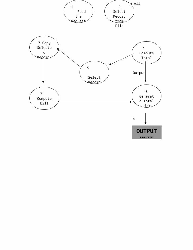
DATA FLOW DIAGRAMLIST OF ALL RECORDS
FILE
Final Output
Output Processing
Processing
Scan All Record
Cash
MANAGEMENT
3 Copy Selected Record

1 Read the Request
2 Select Record
from File
4 Compute
Total5 Select Record
7 Copy Selected Record
7 Compute
bill
8 Generate Total List
To Screen/Printer
OUTPUT UNIT

System Design
The design document that we will develop during this phase is the blueprint of the software. It describes how the solution to the customer problem is to be built. Since solution to complex problems isn’t usually found in the first try, iterations are most likely required. This is true for software design as well. For this reason, any design strategy, design method, or design language must be flexible and must easily accommodate changes due to iterations in the design . Any technique or design needs to support and guide the partitioning process in such a way that the resulting sub-problems are as independent as possible from each other and can be combined easily for the solution to the overall problem. Sub-problem independence and easy combination of their solutions reduces the complexity of the problem. This is the objective of the partitioning process. Partitioning or decomposition during design involves three types of decisions: -Define the boundaries along which to break;Determine into how money pieces to break; andIdentify the proper level of detail when design should stop and implementation should start.Basic design principles that enable the software engineer to navigate the design process suggest a set of principles for software design, which have been adapted and extended in the following list:Free from the suffer from "tunnel vision." A good designer should consider alternative approaches, judging each based on the requirements of the problem, the resources available to do the job.The design should be traceable to the analysis model. Because a single element of the design model often traces to multiple requirements, it is necessary to have a means for tracking how requirements have been satisfied by the design model.The design should not repeat the same thing. Systems are constructed using a set of design patterns, many of which have likely been encountered before. These patterns should always be chosen as an alternative to reinvention. Time is short and resources are limited! Design time should be invested in representing truly new ideas and integrating those patterns that already exist.The design should "minimize the intellectual distance" between the software and the problem as it exists in the real world. That is, the structure of the software design should (whenever possible) mimic the structure of the problem domain.

The design should exhibit uniformity and integration. A design is uniform if it appears that one person developed the entire thing. Rules of style and format should be defined for a design team before design work begins. A design is integrated if care is taken in defining interfaces between design components.The design activity begins when the requirements document for the software to be developed is available. This may be the SRS for the complete system, as is the case if the waterfall model is being followed or the requirements for the next "iteration" if the iterative enhancement is being followed or the requirements for the prototype if the prototyping is being followed. While the requirements specification activity is entirely in the problem domain, design is the first step in moving from the problem domain toward the solution domain. Design is essentially the bridge between requirements specification and the final solution for satisfying the requirements.The design of a system is essentially a blueprint or a plan for a solution for the system. We consider a system to be a set of components with clearly defined behavior that interacts with each other in a fixed defined manner to produce some behavior or services for its environment. A component of a system can be considered a system, with its own components. In a software system, a component is a software module.The design process for software systems, often, has two levels. At the first level, the focus is on deciding which modules are needed for the system, the specifications of these modules, and how the modules should be interconnected. This is what is called the system design or top-level design. In the second level, the internal design of the modules, or how the specifications of the module can be satisfied, is decided. This design level is often called detailed design or logic design. Detailed design essentially expands the system design to contain a more detailed description of the processing logic and data structures so that the design is sufficiently complete for coding.Because the detailed design is an extension of system design, the system design controls the major structural characteristics of the system. The system design has a major impact on the testability and modifiability of a system, and it impacts its efficiency. Much of the design effort for designing software is spent creating the system design.The input to the design phase is the specifications for the system to be designed. Hence, a reasonable entry criteria can be that the specifications are stable and have been approved, hoping that the approval mechanism will ensure that the specifications are complete, consistent, unambiguous, etc. The output of the top-level design phase is the architectural design or the
system design for the software system to be built. This can be produced with or without using a design methodology. A reasonable exit criteria for the phase could be that the design has been verified against the input specifications and has been evaluated and approved for quality.A design can be object-oriented or function-oriented. In function-oriented design, the design consists of module definitions, with each module supporting a functional abstraction. In object-oriented design, the modules in the design represent data abstraction (these abstractions are discussed in more detail later). In the function-oriented methods for design and describe one particular methodology the structured design methodology in some detail. In a function- oriented design approach, a system is viewed as a transformation function, transforming the inputs to the desired outputs. The purpose of the design phase is to specify the components for this transformation function, so that each component is also a transformation function. Hence, the basic output of the system design phase, when a function oriented design approach is being followed, is the definition of all the major data structures in the system, all the major modules of the system, and how the modules interact with each other. Once the designer is satisfied with the design he has produced, the design is to be precisely specified in the form of a document. To specify the design, specification languages are used. Producing the design specification is the ultimate objective of the design phase. The purpose of this design document is quite different from that of the design notation. Whereas a design represented using the design notation is largely to be used by the designer, a design specification has to be so precise and complete that it can be used as a basis of further development by other programmers. Generally, design specification uses textual structures, with design notation helping in understanding.

SchedulingScheduling of a software project does not differ greatly from scheduling of any multi- task engineering effort. Therefore, generalized project scheduling tools and techniques can be applied with little modification to software projects.Program evaluation and review technique (PERT) and critical path method (CPM) are two project scheduling methods that can be applied to software development. Both techniques are driven by information already developed in earlier project planning activities.
Estimates of Effort
A decomposition of the product function The selection of the appropriate process model and task set Decomposition of tasksInterdependencies among tasks may be defined using a task network. Tasks, sometimes called the project Work Breakdown Structure (WBS) are defined for the product as a whole or for individual functions.Both PERT and CPM provide quantitative tools that allow the software planner to (1) determine the critical path-the chain of tasks that determines the duration of the project; (2) establish "most likely" time estimates for individual tasks by applying statistical models; and (3) calculate "boundary times" that define a time window" for a particular task.Boundary time calculations can be very useful in software project scheduling. Slippage in the design of one function, for example, can retard further development of other functions. It describes important boundary times that may be discerned from a PERT or CPM network: (I) the earliest time that a task can begin when preceding tasks are completed in the shortest possible time, (2) the latest time for task initiation before the minimum project completion time is delayed, (3) the earliest finish-the sum of the earliest start and the task duration, (4) the latest finish- the latest start time added to task duration, and (5) the total float-the amount of surplus time or leeway allowed in scheduling tasks so that the network critical path maintained on schedule. Boundary time calculations lead to a determination of critical path and provide the manager with a quantitative method for evaluating progress as tasks are completed.
Both PERT and CPM have been implemented in a wide variety of automated tools that are available for the personal computer. Such tools are easy to use and take the scheduling methods described previously available to every software project manager.

//**********************************************************// PROJECT PAYROLL//**********************************************************
//**********************************************************// INCLUDED HEADER FILES//**********************************************************
#include <iostream.h>#include <fstream.h>#include <process.h>#include <string.h>#include <stdlib.h>#include <stdio.h>#include <ctype.h>#include <conio.h>#include <dos.h>
//**********************************************************// THIS CLASS CONTAINS ALL THE DRAWING FUNCTIONS//**********************************************************
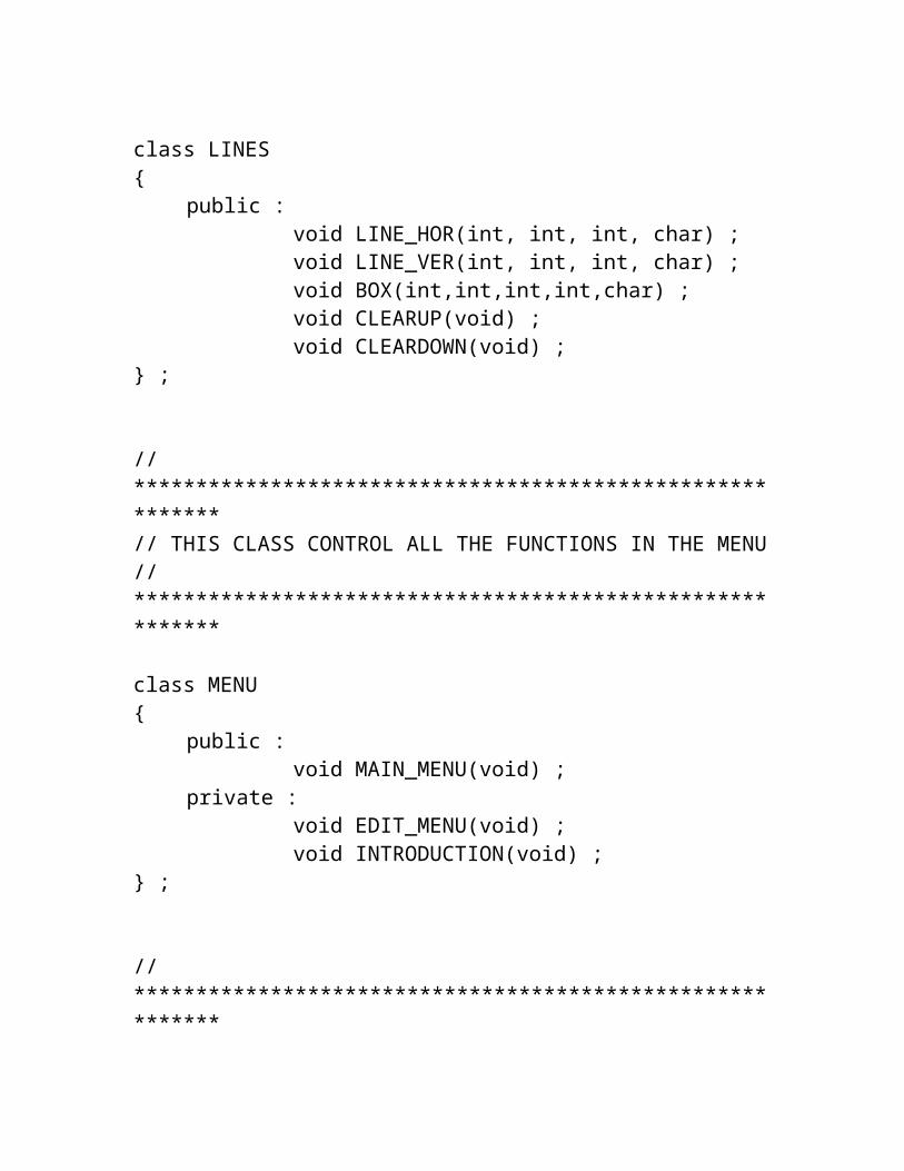
class LINES{
public :void LINE_HOR(int, int, int, char) ;void LINE_VER(int, int, int, char) ;

void BOX(int,int,int,int,char) ;void CLEARUP(void) ;void CLEARDOWN(void) ;
} ;
//**********************************************************// THIS CLASS CONTROL ALL THE FUNCTIONS IN THE MENU//**********************************************************
class MENU{
public :void MAIN_MENU(void) ;
private :void EDIT_MENU(void) ;void INTRODUCTION(void) ;
} ;
//**********************************************************// THIS CLASS CONTROL ALL THE FUNCTIONS RELATED TO EMPLOYEE//**********************************************************
class EMPLOYEE{
public :void NEW_EMPLOYEE(void) ;void MODIFICATION(void) ;void DELETION(void) ;void DISPLAY(void) ;

void LIST(void) ;void SALARY_SLIP(void) ;
private :void ADD_RECORD(int, char[], char[],
char[], int, int, int, char[], char, char, char, float, float) ;
void MODIFY_RECORD(int, char [], char [], char [], char [], char, char, char, float, float) ;
void DELETE_RECORD(int) ;int LASTCODE(void) ;int CODEFOUND(int) ;int RECORDNO(int) ;int FOUND_CODE(int) ;void DISPLAY_RECORD(int) ;int VALID_DATE(int, int, int) ;
int code, dd, mm, yy ;char name[26], address[31],
phone[10], desig[16] ;char grade, house, convense ;float loan, basic ;
} ;
//**********************************************************// THIS FUNCTION CONTROL ALL THE FUNCTIONS IN THE MAIN MENU//**********************************************************
void MENU :: MAIN_MENU(void){
char ch ;LINES L ;L.CLEARUP() ;while (1)

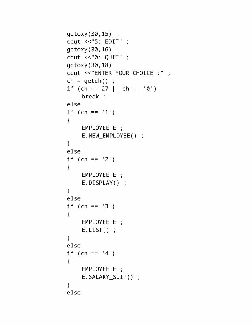
{clrscr() ;L.BOX(28,7,51,9,218) ;L.BOX(10,5,71,21,218) ;L.BOX(11,6,70,20,219) ;gotoxy(31,8) ;cout <<"RAJ SONS PVT. LTD." ;gotoxy(30,11) ;cout <<"1: NEW EMPLOYEE" ;gotoxy(30,12) ;cout <<"2: DISPLAY EMPLOYEE" ;gotoxy(30,13) ;cout <<"3: LIST OF EMPLOYEES" ;gotoxy(30,14) ;cout <<"4: SALARY SLIP" ;gotoxy(30,15) ;cout <<"5: EDIT" ;gotoxy(30,16) ;cout <<"0: QUIT" ;gotoxy(30,18) ;cout <<"ENTER YOUR CHOICE :" ;ch = getch() ;if (ch == 27 || ch == '0')
break ;elseif (ch == '1'){
EMPLOYEE E ;E.NEW_EMPLOYEE() ;
}elseif (ch == '2'){
EMPLOYEE E ;E.DISPLAY() ;
}elseif (ch == '3'){
EMPLOYEE E ;

E.LIST() ;}elseif (ch == '4'){
EMPLOYEE E ;E.SALARY_SLIP() ;
}elseif (ch == '5')
EDIT_MENU() ;}L.CLEARUP() ;
}
//**********************************************************// THIS FUNCTION CONTROL ALL THE FUNCTIONS IN THE EDIT MENU//**********************************************************
void MENU :: EDIT_MENU(void){
char ch ;LINES L ;L.CLEARDOWN() ;while (1){
clrscr() ;L.BOX(28,8,49,10,218) ;L.BOX(10,5,71,21,218) ;L.BOX(11,6,70,20,219) ;gotoxy(31,9) ;cout <<"E D I T M E N U" ;gotoxy(30,13) ;cout <<"1: DELETE RECORD" ;

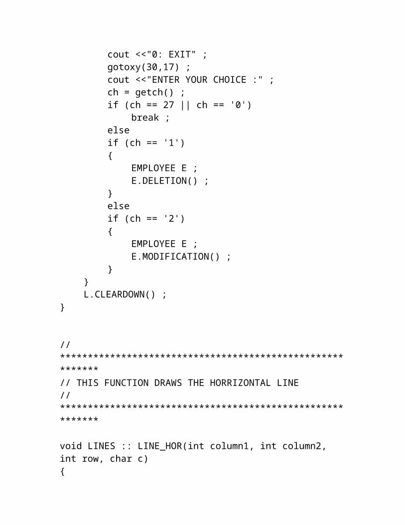
gotoxy(30,14) ;cout <<"2: MODIFY RECORD" ;gotoxy(30,15) ;cout <<"0: EXIT" ;gotoxy(30,17) ;cout <<"ENTER YOUR CHOICE :" ;ch = getch() ;if (ch == 27 || ch == '0')
break ;elseif (ch == '1'){
EMPLOYEE E ;E.DELETION() ;
}elseif (ch == '2'){
EMPLOYEE E ;E.MODIFICATION() ;
}}L.CLEARDOWN() ;
}
//**********************************************************// THIS FUNCTION DRAWS THE HORRIZONTAL LINE//**********************************************************
void LINES :: LINE_HOR(int column1, int column2, int row, char c){
for ( column1; column1<=column2; column1++ ){
gotoxy(column1,row) ;
cout <<c ;}
}
//**********************************************************// THIS FUNCTION DRAWS THE VERTICAL LINE//**********************************************************
void LINES :: LINE_VER(int row1, int row2, int column, char c){
for ( row1; row1<=row2; row1++ ){
gotoxy(column,row1) ;cout <<c ;
}}
//**********************************************************// THIS FUNCTION DRAWS THE BOX//**********************************************************
void LINES :: BOX(int column1, int row1, int column2, int row2, char c){
char ch=218 ;char c1, c2, c3, c4 ;char l1=196, l2=179 ;if (c == ch){

c1=218 ;c2=191 ;c3=192 ;c4=217 ;l1 = 196 ;l2 = 179 ;
}else{
c1=c ;c2=c ;c3=c ;c4=c ;l1 = c ;l2 = c ;
}gotoxy(column1,row1) ;cout <<c1 ;gotoxy(column2,row1) ;cout <<c2 ;gotoxy(column1,row2) ;cout <<c3 ;gotoxy(column2,row2) ;cout <<c4 ;column1++ ;column2-- ;LINE_HOR(column1,column2,row1,l1) ;LINE_HOR(column1,column2,row2,l1) ;column1-- ;column2++ ;row1++ ;row2-- ;LINE_VER(row1,row2,column1,l2) ;LINE_VER(row1,row2,column2,l2) ;
}
//**********************************************************
// THIS FUNCTION CLEAR THE SCREEN LINE BY LINE UPWARD//**********************************************************
void LINES :: CLEARUP(void){
for (int i=25; i>=1; i--){
delay(20) ;gotoxy(1,i) ; clreol() ;
}}
//**********************************************************// THIS FUNCTION CLEAR THE SCREEN LINE BY LINE DOWNWORD//**********************************************************
void LINES :: CLEARDOWN(void){
for (int i=1; i<=25; i++){
delay(20) ;gotoxy(1,i) ; clreol() ;
}}
//**********************************************************// THIS FUNCTION ADDS THE GIVEN DATA IN THE EMPLOYEE'S FILE

//**********************************************************
void EMPLOYEE :: ADD_RECORD(int ecode, char ename[26], char eaddress[31], char ephone[10], int d, int m, int y, char edesig[16], char egrade, char ehouse, char econv, float eloan, float ebasic){
fstream file ;file.open("EMPLOYEE.DAT", ios::app) ;code = ecode ;strcpy(name,ename) ;strcpy(address,eaddress) ;strcpy(phone,ephone) ;dd = d ;mm = m ;yy = y ;strcpy(desig,edesig) ;grade = egrade ;house = ehouse ;convense = econv ;loan = eloan ;basic = ebasic ;file.write((char *) this, sizeof(EMPLOYEE)) ;file.close() ;
}
//**********************************************************// THIS FUNCTION MODIFY THE GIVEN DATA IN THE// EMPLOYEE'S FILE//**********************************************************
void EMPLOYEE :: MODIFY_RECORD(int ecode, char ename[26], char eaddress[31], char ephone[10], char

edesig[16], char egrade, char ehouse, char econv, float eloan, float ebasic){
int recno ;recno = RECORDNO(ecode) ;fstream file ;file.open("EMPLOYEE.DAT", ios::out |
ios::ate) ;strcpy(name,ename) ;strcpy(address,eaddress) ;strcpy(phone,ephone) ;strcpy(desig,edesig) ;grade = egrade ;house = ehouse ;convense = econv ;loan = eloan ;basic = ebasic ;int location ;location = (recno-1) * sizeof(EMPLOYEE) ;file.seekp(location) ;file.write((char *) this, sizeof(EMPLOYEE)) ;file.close() ;
}
//**********************************************************// THIS FUNCTION DELETE THE RECORD IN THE EMPLOYEE FILE// FOR THE GIVEN EMPLOYEE CODE//**********************************************************
void EMPLOYEE :: DELETE_RECORD(int ecode){
fstream file ;file.open("EMPLOYEE.DAT", ios::in) ;fstream temp ;
temp.open("temp.dat", ios::out) ;file.seekg(0,ios::beg) ;while (!file.eof()){
file.read((char *) this, sizeof(EMPLOYEE)) ;
if (file.eof())break ;
if (code != ecode)temp.write((char *) this,
sizeof(EMPLOYEE)) ;}file.close() ;temp.close() ;file.open("EMPLOYEE.DAT", ios::out) ;temp.open("temp.dat", ios::in) ;temp.seekg(0,ios::beg) ;while (!temp.eof()){
temp.read((char *) this, sizeof(EMPLOYEE)) ;
if ( temp.eof() )break ;
file.write((char *) this, sizeof(EMPLOYEE)) ;
}file.close() ;temp.close() ;
}
//**********************************************************// THIS FUNCTION RETURNS THE LAST EMPLOYEE'S CODE//**********************************************************
int EMPLOYEE :: LASTCODE(void)
{fstream file ;file.open("EMPLOYEE.DAT", ios::in) ;file.seekg(0,ios::beg) ;int count=0 ;while (file.read((char *) this,
sizeof(EMPLOYEE)))count = code ;
file.close() ;return count ;
}
//**********************************************************// THIS FUNCTION RETURNS 0 IF THE GIVEN CODE NOT FOUND//**********************************************************
int EMPLOYEE :: FOUND_CODE(int ecode){
fstream file ;file.open("EMPLOYEE.DAT", ios::in) ;file.seekg(0,ios::beg) ;int found=0 ;while (file.read((char *) this,
sizeof(EMPLOYEE))){
if (code == ecode){
found = 1 ;break ;
}}file.close() ;return found ;
}

//**********************************************************// THIS FUNCTION RETURNS RECORD NO. OF THE GIVEN CODE//**********************************************************
int EMPLOYEE :: RECORDNO(int ecode){
fstream file ;file.open("EMPLOYEE.DAT", ios::in) ;file.seekg(0,ios::beg) ;int recno=0 ;while (file.read((char *) this,
sizeof(EMPLOYEE))){
recno++ ;if (code == ecode)
break ;}file.close() ;return recno ;
}
//**********************************************************// THIS FUNCTION DISPLAYS THE LIST OF THE EMPLOYEES//**********************************************************
void EMPLOYEE :: LIST(void){
clrscr() ;
int row = 6 , found=0, flag=0 ;char ch ;gotoxy(31,2) ;cout <<"LIST OF EMPLOYEES" ;gotoxy(30,3) ;cout <<"~~~~~~~~~~~~~~~~~~~" ;gotoxy(1,4) ;cout <<"CODE NAME PHONE
DOJ DESIGNATION GRADE SALARY" ;gotoxy(1,5) ;cout
<<"~~~~~~~~~~~~~~~~~~~~~~~~~~~~~~~~~~~~~~~~~~~~~~~~~~~~~~~~~~~~~~~~~~~~~~~~~~~~~~~" ;
fstream file ;file.open("EMPLOYEE.DAT", ios::in) ;file.seekg(0,ios::beg) ;while (file.read((char *) this,
sizeof(EMPLOYEE))){
flag = 0 ;delay(20) ;found = 1 ;gotoxy(2,row) ;cout <<code ;gotoxy(6,row) ;cout <<name ;gotoxy(31,row) ;cout<<phone ;gotoxy(40,row) ;cout <<dd <<"/" <<mm <<"/" <<yy ;gotoxy(52,row) ;cout <<desig ;gotoxy(69,row) ;cout <<grade ;if (grade != 'E'){
gotoxy(74,row) ;cout <<basic ;
}else

{gotoxy(76,row) ;cout <<"-" ;
}if ( row == 23 ){
flag = 1 ;row = 6 ;gotoxy(1,25) ;cout <<"Press any key to continue or
Press <ESC> to exit" ;ch = getch() ;if (ch == 27)
break ;clrscr() ;gotoxy(31,2) ;cout <<"LIST OF EMPLOYEES" ;gotoxy(30,3) ;cout <<"~~~~~~~~~~~~~~~~~~~" ;gotoxy(1,4) ;cout <<"CODE NAME
PHONE DOJ DESIGNATION GRADE SALARY" ;
gotoxy(1,5) ;cout
<<"~~~~~~~~~~~~~~~~~~~~~~~~~~~~~~~~~~~~~~~~~~~~~~~~~~~~~~~~~~~~~~~~~~~~~~~~~~~~~~~" ;
}else
row++ ;}if (!found){
gotoxy(5,10) ;cout <<"\7Records not found" ;
}if (!flag){
gotoxy(1,25) ;cout <<"Press any key to continue..." ;
getche() ;}file.close () ;
}
//**********************************************************// THIS FUNCTION DISPLAYS THE RECORD OF THE EMPLOYEES//**********************************************************
void EMPLOYEE :: DISPLAY_RECORD(int ecode){
fstream file ;file.open("EMPLOYEE.DAT", ios::in) ;file.seekg(0,ios::beg) ;while (file.read((char *) this,
sizeof(EMPLOYEE))){
if (code == ecode){
gotoxy(5,5) ;cout <<"Employee Code # " <<code ;gotoxy(5,6) ;cout <<"~~~~~~~~~~~~~" ;gotoxy(5,7) ;cout <<"Name : " <<name ;gotoxy(5,8) ;cout <<"Address : " <<address ;gotoxy(5,9) ;cout <<"Phone no. : " <<phone ;gotoxy(5,11) ;cout <<"JOINING DATE" ;gotoxy(5,12) ;cout <<"~~~~~~~~~~~~" ;gotoxy(5,13) ;

cout <<"Day : " <<dd ;gotoxy(5,14) ;cout <<"Month : " <<mm ;gotoxy(5,15) ;cout <<"Year : " <<yy ;gotoxy(5,17) ;cout <<"Designation : " <<desig ;gotoxy(5,18) ;cout <<"Grade : " <<grade ;if (grade != 'E'){
gotoxy(5,19) ;cout <<"House (y/n) : " <<house
;gotoxy(5,20) ;cout <<"Convense (y/n) : "
<<convense ;gotoxy(5,22) ;cout <<"Basic Salary : " <<basic
;}gotoxy(5,21) ;cout <<"Loan : " <<loan ;
}}file.close() ;
}
//**********************************************************// THIS FUNCTION GIVE DATA TO ADD IN THE FILE//**********************************************************
void EMPLOYEE :: NEW_EMPLOYEE(void){
clrscr() ;
char ch, egrade, ehouse='N', econv='N' ;char ename[26], eaddress[31], ephone[10],
edesig[16], t1[10] ;float t2=0.0, eloan=0.0, ebasic=0.0 ;int d, m, y, ecode, valid ;gotoxy(72,2) ;cout <<"<0>=EXIT" ;gotoxy(28,3) ;cout <<"ADDITION OF NEW EMPLOYEE" ;gotoxy(5,5) ;cout <<"Employee Code # " ;gotoxy(5,6) ;cout <<"~~~~~~~~~~~~~" ;gotoxy(5,7) ;cout <<"Name : " ;gotoxy(5,8) ;cout <<"Address : " ;gotoxy(5,9) ;cout <<"Phone no. : " ;gotoxy(5,11) ;cout <<"JOINING DATE" ;gotoxy(5,12) ;cout <<"~~~~~~~~~~~~" ;gotoxy(5,13) ;cout <<"Day : " ;gotoxy(5,14) ;cout <<"Month : " ;gotoxy(5,15) ;cout <<"Year : " ;gotoxy(5,17) ;cout <<"Designation : " ;gotoxy(5,18) ;cout <<"Grade : " ;gotoxy(5,21) ;cout <<"Loan : " ;
ecode = LASTCODE() + 1 ;if (ecode == 1){

ADD_RECORD(ecode, "null", "null", "null", 0, 0, 0, "null", 'n', 'n', 'n', 0.0, 0.0) ;
DELETE_RECORD(ecode) ;}gotoxy(21,5) ;cout <<ecode ;do{
valid = 1 ;gotoxy(5,25) ; clreol() ;cout <<"Enter the name of the Employee" ;gotoxy(20,7) ; clreol() ;gets(ename) ;strupr(ename) ;if (ename[0] == '0')
return ;if (strlen(ename) < 1 || strlen(ename) >
25){
valid = 0 ;gotoxy(5,25) ; clreol() ;cout <<"\7Enter correctly (Range:
1..25)" ;getch() ;
}} while (!valid) ;do{
valid = 1 ;gotoxy(5,25) ; clreol() ;cout <<"Enter Address of the Employee" ;gotoxy(20,8) ; clreol() ;gets(eaddress) ;strupr(eaddress) ;if (eaddress[0] == '0')
return ;if (strlen(eaddress) < 1 ||
strlen(eaddress) > 30){
valid = 0 ;

gotoxy(5,25) ; clreol() ;cout <<"\7Enter correctly (Range:
1..30)" ;getch() ;
}} while (!valid) ;do{
valid = 1 ;gotoxy(5,25) ; clreol() ;cout <<"Enter Phone no. of the Employee or
Press <ENTER> for none" ;gotoxy(20,9) ; clreol() ;gets(ephone) ;if (ephone[0] == '0')
return ;if ((strlen(ephone) < 7 && strlen(ephone)
> 0) || (strlen(ephone) > 9)){
valid = 0 ;gotoxy(5,25) ; clreol() ;cout <<"\7Enter correctly" ;getch() ;
}} while (!valid) ;if (strlen(ephone) == 0)
strcpy(ephone,"-") ;char tday[3], tmonth[3], tyear[5] ;int td ;do{
valid = 1 ;do{
gotoxy(5,25) ; clreol() ;cout <<"ENTER DAY OF JOINING" ;gotoxy(13,13) ; clreol() ;gets(tday) ;td = atoi(tday) ;d = td ;
if (tday[0] == '0')return ;
} while (d == 0) ;do{
gotoxy(5,25) ; clreol() ;cout <<"ENTER MONTH OF JOINING" ;gotoxy(13,14) ; clreol() ;gets(tmonth) ;td = atoi(tmonth) ;m = td ;if (tmonth[0] == '0')
return ;} while (m == 0) ;do{
gotoxy(5,25) ; clreol() ;cout <<"ENTER YEAR OF JOINING" ;gotoxy(13,15) ; clreol() ;gets(tyear) ;td = atoi(tyear) ;y = td ;if (tyear[0] == '0')
return ;} while (y == 0) ;if (d>31 || d<1)
valid = 0 ;elseif (((y%4)!=0 && m==2 && d>28) || ((y
%4)==0 && m==2 && d>29))valid = 0 ;
elseif ((m==4 || m==6 || m==9 || m==11) &&
d>30)valid = 0 ;
elseif (y<1990 || y>2020)
valid = 0 ;if (!valid){

valid = 0 ;gotoxy(5,25) ; clreol() ;cout <<"\7Enter correctly" ;getch() ;gotoxy(13,14) ; clreol() ;gotoxy(13,15) ; clreol() ;
}} while (!valid) ;do{
valid = 1 ;gotoxy(5,25) ; clreol() ;cout <<"Enter Designation of the Employee"
;gotoxy(20,17) ; clreol() ;gets(edesig) ;strupr(edesig) ;if (edesig[0] == '0')
return ;if (strlen(edesig) < 1 || strlen(edesig) >
15){
valid = 0 ;gotoxy(5,25) ; clreol() ;cout <<"\7Enter correctly (Range:
1..15)" ;getch() ;
}} while (!valid) ;do{
gotoxy(5,25) ; clreol() ;cout <<"Enter Grade of the Employee
(A,B,C,D,E)" ;gotoxy(20,18) ; clreol() ;egrade = getche() ;egrade = toupper(egrade) ;if (egrade == '0')
return ;} while (egrade < 'A' || egrade > 'E') ;
if (egrade != 'E'){
gotoxy(5,19) ;cout <<"House (y/n) : " ;gotoxy(5,20) ;cout <<"Convense (y/n) : " ;gotoxy(5,22) ;cout <<"Basic Salary : " ;do{
gotoxy(5,25) ; clreol() ;cout <<"ENTER IF HOUSE ALLOWANCE IS
ALLOTED TO EMPLOYEE OR NOT" ;gotoxy(22,19) ; clreol() ;ehouse = getche() ;ehouse = toupper(ehouse) ;if (ehouse == '0')
return ;} while (ehouse != 'Y' && ehouse != 'N') ;do{
gotoxy(5,25) ; clreol() ;cout <<"ENTER IF CONVENCE ALLOWANCE IS
ALLOTED TO EMPLOYEE OR NOT" ;gotoxy(22,20) ; clreol() ;econv = getche() ;econv = toupper(econv) ;if (econv == '0')
return ;} while (econv != 'Y' && econv != 'N') ;
}do{
valid = 1 ;gotoxy(5,25) ; clreol() ;cout <<"ENTER LOAN AMOUNT IF ISSUED" ;gotoxy(22,21) ; clreol() ;gets(t1) ;t2 = atof(t1) ;eloan = t2 ;

if (eloan > 50000){
valid = 0 ;gotoxy(5,25) ; clreol() ;cout <<"\7SHOULD NOT GREATER THAN
50000" ;getch() ;
}} while (!valid) ;if (egrade != 'E'){
do{
valid = 1 ;gotoxy(5,25) ; clreol() ;cout <<"ENTER BASIC SALARY OF THE
EMPLOYEE" ;gotoxy(22,22) ; clreol() ;gets(t1) ;t2 = atof(t1) ;ebasic = t2 ;if (t1[0] == '0')
return ;if (ebasic > 50000){
valid = 0 ;gotoxy(5,25) ; clreol() ;cout <<"\7SHOULD NOT GREATER THAN
50000" ;getch() ;
}} while (!valid) ;
}gotoxy(5,25) ; clreol() ;do{
gotoxy(5,24) ; clreol() ;cout <<"Do you want to save (y/n) " ;ch = getche() ;ch = toupper(ch) ;
if (ch == '0')return ;
} while (ch != 'Y' && ch != 'N') ;if (ch == 'N')
return ;ADD_RECORD(ecode, ename, eaddress, ephone, d,
m, y, edesig, egrade, ehouse, econv, eloan, ebasic) ;}
//**********************************************************// THIS FUNCTION GIVE CODE FOR THE DISPLAY OF THE RECORD//**********************************************************
void EMPLOYEE :: DISPLAY(void){
clrscr() ;char t1[10] ;int t2, ecode ;gotoxy(72,2) ;cout <<"<0>=EXIT" ;gotoxy(5,5) ;cout <<"Enter code of the Employee " ;gets(t1) ;t2 = atoi(t1) ;ecode = t2 ;if (ecode == 0)
return ;clrscr() ;if (!FOUND_CODE(ecode)){
gotoxy(5,5) ;cout <<"\7Record not found" ;getch() ;
return ;}DISPLAY_RECORD(ecode) ;gotoxy(5,25) ;cout <<"Press any key to continue..." ;getch() ;
}
//**********************************************************// THIS FUNCTION GIVE DATA FOR THE MODIFICATION OF THE// EMPLOYEE RECORD//**********************************************************
void EMPLOYEE :: MODIFICATION(void){
clrscr() ;char ch, egrade, ehouse='N', econv='N' ;char ename[26], eaddress[31], ephone[10],
edesig[16], t1[10] ;float t2=0.0, eloan=0.0, ebasic=0.0 ;int ecode, valid ;gotoxy(72,2) ;cout <<"<0>=EXIT" ;gotoxy(5,5) ;cout <<"Enter code of the Employee " ;gets(t1) ;t2 = atoi(t1) ;ecode = t2 ;if (ecode == 0)
return ;clrscr() ;if (!FOUND_CODE(ecode)){
gotoxy(5,5) ;

cout <<"\7Record not found" ;getch() ;return ;
}gotoxy(72,2) ;cout <<"<0>=EXIT" ;gotoxy(22,3) ;cout <<"MODIFICATION OF THE EMPLOYEE RECORD" ;DISPLAY_RECORD(ecode) ;do{
gotoxy(5,24) ; clreol() ;cout <<"Do you want to modify this record
(y/n) " ;ch = getche() ;ch = toupper(ch) ;if (ch == '0')
return ;} while (ch != 'Y' && ch != 'N') ;if (ch == 'N')
return ;clrscr() ;fstream file ;file.open("EMPLOYEE.DAT", ios::in) ;file.seekg(0,ios::beg) ;while (file.read((char *) this,
sizeof(EMPLOYEE))){
if (code == ecode)break ;
}file.close() ;gotoxy(5,5) ;cout <<"Employee Code # " <<ecode ;gotoxy(5,6) ;cout <<"~~~~~~~~~~~~~" ;gotoxy(40,5) ;cout <<"JOINING DATE : " ;gotoxy(40,6) ;cout <<"~~~~~~~~~~~~~~" ;
gotoxy(55,5) ;cout <<dd <<"/" <<mm <<"/" <<yy ;gotoxy(5,7) ;cout <<"Name : " ;gotoxy(5,8) ;cout <<"Address : " ;gotoxy(5,9) ;cout <<"Phone no. : " ;gotoxy(5,10) ;cout <<"Designation : " ;gotoxy(5,11) ;cout <<"Grade : " ;gotoxy(5,14) ;cout <<"Loan : " ;do{
valid = 1 ;gotoxy(5,25) ; clreol() ;cout <<"Enter the name of the Employee or
<ENTER> FOR NO CHANGE" ;gotoxy(20,7) ; clreol() ;gets(ename) ;strupr(ename) ;if (ename[0] == '0')
return ;if (strlen(ename) > 25){
valid = 0 ;gotoxy(5,25) ; clreol() ;cout <<"\7Enter correctly (Range:
1..25)" ;getch() ;
}} while (!valid) ;if (strlen(ename) == 0){
strcpy(ename,name) ;gotoxy(20,7) ;cout <<ename ;
}

do{
valid = 1 ;gotoxy(5,25) ; clreol() ;cout <<"Enter Address of the Employee or
<ENTER> FOR NO CHANGE" ;gotoxy(20,8) ; clreol() ;gets(eaddress) ;strupr(eaddress) ;if (eaddress[0] == '0')
return ;if (strlen(eaddress) > 30){
valid = 0 ;gotoxy(5,25) ; clreol() ;cout <<"\7Enter correctly (Range:
1..30)" ;getch() ;
}} while (!valid) ;if (strlen(eaddress) == 0){
strcpy(eaddress,address) ;gotoxy(20,8) ;cout <<eaddress ;
}do{
valid = 1 ;gotoxy(5,25) ; clreol() ;cout <<"Enter Phone no. of the Employee or
or <ENTER> FOR NO CHANGE" ;gotoxy(20,9) ; clreol() ;gets(ephone) ;if (ephone[0] == '0')
return ;if ((strlen(ephone) < 7 && strlen(ephone)
> 0) || (strlen(ephone) > 9)){
valid = 0 ;

gotoxy(5,25) ; clreol() ;cout <<"\7Enter correctly" ;getch() ;
}} while (!valid) ;if (strlen(ephone) == 0){
strcpy(ephone,phone) ;gotoxy(20,9) ;cout <<ephone ;
}do{
valid = 1 ;gotoxy(5,25) ; clreol() ;cout <<"Enter Designation of the Employee
or <ENTER> FOR NO CHANGE" ;gotoxy(20,10) ; clreol() ;gets(edesig) ;strupr(edesig) ;if (edesig[0] == '0')
return ;if (strlen(edesig) > 15){
valid = 0 ;gotoxy(5,25) ; clreol() ;cout <<"\7Enter correctly (Range:
1..15)" ;getch() ;
}} while (!valid) ;if (strlen(edesig) == 0){
strcpy(edesig,desig) ;gotoxy(20,10) ;cout <<edesig ;
}do{
gotoxy(5,25) ; clreol() ;
cout <<"Enter Grade of the Employee (A,B,C,D,E) or <ENTER> FOR NO CHANGE" ;
gotoxy(20,11) ; clreol() ;egrade = getche() ;egrade = toupper(egrade) ;if (egrade == '0')
return ;if (egrade == 13){
egrade = grade ;gotoxy(20,11) ;cout <<grade ;
}} while (egrade < 'A' || egrade > 'E') ;if (egrade != 'E'){
gotoxy(5,12) ;cout <<"House (y/n) : " ;gotoxy(5,13) ;cout <<"Convense (y/n) : " ;gotoxy(5,15) ;cout <<"Basic Salary : " ;do{
gotoxy(5,25) ; clreol() ;cout <<"ALLOTED HOUSE ALLOWANCE ? or
<ENTER> FOR NO CHANGE" ;gotoxy(22,12) ; clreol() ;ehouse = getche() ;ehouse = toupper(ehouse) ;if (ehouse == '0')
return ;if (ehouse == 13){
ehouse = house ;gotoxy(22,12) ;cout <<ehouse ;
}} while (ehouse != 'Y' && ehouse != 'N') ;do
{gotoxy(5,25) ; clreol() ;cout <<"ALLOTED CONVENCE ALLOWANCE or
<ENTER> FOR NO CHANGE" ;gotoxy(22,13) ; clreol() ;econv = getche() ;econv = toupper(econv) ;if (econv == '0')
return ;if (econv == 13){
econv = convense ;gotoxy(22,13) ;cout <<econv ;
}} while (econv != 'Y' && econv != 'N') ;
}do{
valid = 1 ;gotoxy(5,25) ; clreol() ;cout <<"ENTER LOAN AMOUNT or <ENTER> FOR
NO CHANGE" ;gotoxy(22,14) ; clreol() ;gets(t1) ;t2 = atof(t1) ;eloan = t2 ;if (eloan > 50000){
valid = 0 ;gotoxy(5,25) ; clreol() ;cout <<"\7SHOULD NOT GREATER THAN
50000" ;getch() ;
}} while (!valid) ;if (strlen(t1) == 0){
eloan = loan ;gotoxy(22,14) ;

cout <<eloan ;}if (egrade != 'E'){
do{
valid = 1 ;gotoxy(5,25) ; clreol() ;cout <<"ENTER BASIC SALARY or <ENTER>
FOR NO CHANGE" ;gotoxy(22,15) ; clreol() ;gets(t1) ;t2 = atof(t1) ;ebasic = t2 ;if (t1[0] == '0')
return ;if (ebasic > 50000){
valid = 0 ;gotoxy(5,25) ; clreol() ;cout <<"\7SHOULD NOT GREATER THAN
50000" ;getch() ;
}} while (!valid) ;if (strlen(t1) == 0){
ebasic = basic ;gotoxy(22,15) ;cout <<ebasic ;
}}gotoxy(5,25) ; clreol() ;do{
gotoxy(5,18) ; clreol() ;cout <<"Do you want to save (y/n) " ;ch = getche() ;ch = toupper(ch) ;if (ch == '0')

return ;} while (ch != 'Y' && ch != 'N') ;if (ch == 'N')
return ;
MODIFY_RECORD(ecode,ename,eaddress,ephone,edesig,egrade,ehouse,econv,eloan,ebasic) ;
gotoxy(5,23) ;cout <<"\7Record Modified" ;gotoxy(5,25) ;cout <<"Press any key to continue..." ;getch() ;
}
//**********************************************************// THIS FUNCTION GIVE CODE NO. FOR THE DELETION OF THE// EMPLOYEE RECORD//**********************************************************
void EMPLOYEE :: DELETION(void){
clrscr() ;char t1[10], ch ;int t2, ecode ;gotoxy(72,2) ;cout <<"<0>=EXIT" ;gotoxy(5,5) ;cout <<"Enter code of the Employee " ;gets(t1) ;t2 = atoi(t1) ;ecode = t2 ;if (ecode == 0)
return ;clrscr() ;

if (!FOUND_CODE(ecode)){
gotoxy(5,5) ;cout <<"\7Record not found" ;getch() ;return ;
}gotoxy(72,2) ;cout <<"<0>=EXIT" ;gotoxy(24,3) ;cout <<"DELETION OF THE EMPLOYEE RECORD" ;DISPLAY_RECORD(ecode) ;do{
gotoxy(5,24) ; clreol() ;cout <<"Do you want to delete this record
(y/n) " ;ch = getche() ;ch = toupper(ch) ;if (ch == '0')
return ;} while (ch != 'Y' && ch != 'N') ;if (ch == 'N')
return ;DELETE_RECORD(ecode) ;LINES L ;L.CLEARDOWN() ;gotoxy(5,23) ;cout <<"\7Record Deleted" ;gotoxy(5,25) ;cout <<"Press any key to continue..." ;getch() ;
}
//**********************************************************// THIS FUNCTION RETURN 0 IF THE GIVEN DATE IS INVALID

//**********************************************************
int EMPLOYEE :: VALID_DATE(int d1, int m1, int y1){
int valid=1 ;if (d1>31 || d1<1)
valid = 0 ;elseif (((y1%4)!=0 && m1==2 && d1>28) || ((y1%4)==0
&& m1==2 && d1>29))valid = 0 ;
elseif ((m1==4 || m1==6 || m1==9 || m1==11) &&
d1>30)valid = 0 ;
return valid ;}
//**********************************************************// THIS FUNCTION PRINTS THE SALARY SLIP FOR THE EMPLOYEE//**********************************************************
void EMPLOYEE :: SALARY_SLIP(void){
clrscr() ;char t1[10] ;int t2, ecode, valid ;gotoxy(72,2) ;cout <<"<0>=EXIT" ;gotoxy(5,5) ;cout <<"Enter code of the Employee " ;gets(t1) ;

t2 = atoi(t1) ;ecode = t2 ;if (ecode == 0)
return ;clrscr() ;if (!FOUND_CODE(ecode)){
gotoxy(5,5) ;cout <<"\7Record not found" ;getch() ;return ;
}fstream file ;file.open("EMPLOYEE.DAT", ios::in) ;file.seekg(0,ios::beg) ;while (file.read((char *) this,
sizeof(EMPLOYEE))){
if (code == ecode)break ;
}file.close() ;int d1, m1, y1 ;struct date d;getdate(&d);d1 = d.da_day ;m1 = d.da_mon ;y1 = d.da_year ;char
*mon[12]={"January","February","March","April","May","June","July","August","September","November","December"} ;
LINES L ;L.BOX(2,1,79,25,219) ;gotoxy(31,2) ;cout <<"RAJ SONS PVT. LTD." ;L.LINE_HOR(3,78,3,196) ;gotoxy(34,4) ;cout <<"SALARY SLIP" ;gotoxy(60,4) ;

cout <<"Date: " <<d1 <<"/" <<m1 <<"/" <<y1 ;gotoxy(34,5) ;cout <<mon[m1-1] <<", " <<y1 ;L.LINE_HOR(3,78,6,196) ;gotoxy(6,7) ;cout <<"Employee Name : " <<name ;gotoxy(6,8) ;cout <<"Designation : " <<desig ;gotoxy(67,8) ;cout <<"Grade : " <<grade ;L.BOX(6,9,75,22,218) ;L.LINE_HOR(10,71,20,196) ;int days, hours ;if (grade == 'E'){
do{
valid = 1 ;gotoxy(10,21) ;cout <<"ENTER NO. OF DAYS WORKED IN
THE MONTH " ;gotoxy(10,11) ;cout <<"No. of Days : " ;gets(t1) ;t2 = atof(t1) ;days = t2 ;if (!VALID_DATE(days,m1,y1)){
valid = 0 ;gotoxy(10,21) ;cout <<"\7ENTER CORRECTLY
" ;getch() ;gotoxy(10,11) ;cout <<" " ;
}} while (!valid) ;do{
valid = 1 ;

gotoxy(10,21) ;cout <<"ENTER NO. OF HOURS WORKED OVER
TIME " ;gotoxy(10,13) ;cout <<"No. of hours : " ;gets(t1) ;t2 = atof(t1) ;hours = t2 ;if (hours > 8 || hours < 0){
valid = 0 ;gotoxy(10,21) ;cout <<"\7ENTER CORRECTLY
" ;getch() ;gotoxy(10,13) ;cout <<" " ;
}} while (!valid) ;gotoxy(10,21) ;cout <<"
" ;gotoxy(10,11) ;cout <<" " ;gotoxy(10,13) ;cout <<" " ;
}gotoxy(10,10) ;cout <<"Basic Salary : Rs." ;gotoxy(10,12) ;cout <<"ALLOWANCE" ;if (grade != 'E'){
gotoxy(12,13) ;cout <<"HRA : Rs." ;gotoxy(12,14) ;cout <<"CA : Rs." ;gotoxy(12,15) ;cout <<"DA : Rs." ;
}
else{
gotoxy(12,13) ;cout <<"OT : Rs." ;
}gotoxy(10,17) ;cout <<"DEDUCTIONS" ;gotoxy(12,18) ;cout <<"LD : Rs." ;if (grade != 'E'){
gotoxy(12,19) ;cout <<"PF : Rs." ;
}gotoxy(10,21) ;cout <<"NET SALARY : Rs." ;gotoxy(6,24) ;cout <<"CASHIER" ;gotoxy(68,24) ;cout <<"EMPLOYEE" ;float HRA=0.0, CA=0.0, DA=0.0, PF=0.0, LD=0.0,
OT=0.0, allowance, deduction, netsalary ;if (grade != 'E'){
if (house == 'Y')HRA = (5*basic)/100 ;
if (convense == 'Y')CA = (2*basic)/100 ;
DA = (5*basic)/100 ;PF = (2*basic)/100 ;LD = (15*loan)/100 ;allowance = HRA+CA+DA ;deduction = PF+LD ;
}else{
basic = days * 30 ;LD = (15*loan)/100 ;OT = hours * 10 ;allowance = OT ;
deduction = LD ;}netsalary = (basic+allowance)-deduction ;gotoxy(36,10) ;cout <<basic ;if (grade != 'E'){
gotoxy(22,13) ;cout <<HRA ;gotoxy(22,14) ;cout <<CA ;gotoxy(22,15) ;cout <<DA ;gotoxy(22,19) ;cout <<PF ;
}else{
gotoxy(22,13) ;cout <<OT ;
}gotoxy(22,18) ;cout <<LD ;gotoxy(33,15) ;cout <<"Rs." <<allowance ;gotoxy(33,19) ;cout <<"Rs." <<deduction ;gotoxy(36,21) ;cout <<netsalary ;gotoxy(2,1) ;getch() ;
}
//**********************************************************// MAIN FUNCTION CALLING MAIN MENU

//**********************************************************
void main(void){
MENU menu ;menu.MAIN_MENU() ;
}
TESTING
In a software development project, errors can be injected at any stage during development. There are different techniques for detecting and eliminating errors that originate in that phase. However, no technique is perfect, and it is expected that some of the errors of the earlier phases will finally manifest themselves in the code. This is particularly true because in the earlier phases and most of the verification techniques are manual because no executable code exists. Ultimately, these remaining errors will be reflected in the code. Hence, the code developed during the coding activity is likely to have some requirement errors and design errors, in addition to errors introduced during the coding activity. Behavior can be observed, testing is the phase where the errors remaining from all the previous phases must be detected. Hence, testing performs a very critical role for quality assurance and for ensuring the reliability of software.
During testing, the program to be tested is executed with a set of test cases, and the output of the program for the test cases is evaluated to determine if the program is performing as expected. Due to its approach, dynamic testing can only ascertain the presence of errors in the program; the exact nature of the errors is not usually decided by testing. Testing forms the first step in determining the errors in a program. Clearly, the success of testing in revealing errors in programs depends critically on the test cases.
Testing a large system is a very complex activity, and like any complex activity it has to be broken into smaller activities. Due to this, for a project, incremental testing is generally performed, in which components and subsystems of the system are tested separately before integrating them to form the system for system testing. This form of testing, though necessary to ensure quality for a large system, introduces new issues of how to select components for testing and how to combine them to form subsystems and systems.
Top-Down and Bottom-Up Approaches Generally, parts of the program are tested before testing the entire program. Besides, partitioning the problem of testing, another reason for testing parts separately is that if a test case detects an error in a large program, it will be extremely difficult to pinpoint the source of the error. That is, if a huge program does not work, determining which module has errors can be a formidable task. Furthermore, it will be extremely difficult to construct test cases so that different modules are executed in a sufficient number of different conditions so that we can feel fairly confident about them. In many cases, it is even difficult to construct test cases so that all the modules will be executed. This increases the chances of a module's errors going undetected. Hence, it is clear that for a large system, we should first test different parts of the system independently, before testing the entire system.
In incremental testing, some parts of the system are first tested independently. Then, these parts are combined to form a (sub) system, which is then tested independently. This combination can be done in two ways: either only the modules that have been tested independently are combined or some new untested modules are combined with tested modules. Both of these approaches require that the order in which modules are to be tested and integrated be planned before commencing testing.
We assume that a system is a hierarchy of modules. For such systems, there are two common ways modules can be combined, as they are tested, to form a working program: top-down and bottom-up. In top-down strategy, we start by testing the top of the hierarchy, and we incrementally add modules that it calls and then test the new combined system. This approach of testing requires stubs to be

written. A stub is a dummy routine that simulates a module. In the top-down approach, a module (or a collection) cannot be tested in isolation because they invoke some other modules. To allow the modules to be tested before their subordinates have been coded, stubs simulate the behavior of the subordinates.
The bottom-up approach starts from the bottom of the hierarchy. First, the modules at the very bottom, which have no subordinates, are tested. Then these modules are combined with higher-level modules for testing. At any stage of testing, all the subordinate modules exist and have been tested earlier. To perform bottom-up testing, drivers are needed to set up the appropriate environment and invoke the module. It is the job of the driver to invoke the module under testing with the different set of test cases.
Notice that both top-down and bottom-up approaches are incremental, starting with testing single modules and then adding untested modules to those that have been tested, until the entire system is tested. In the first case, stubs must be written to perform testing, and in the other, drivers need to be written. Top-down testing is advantageous, if major flaws occur toward the top of the hierarchy, while bottom-up is advantageous if the major flaws occur toward the bottom. Often, writing stubs can be more difficult than writing drivers, because one may need to know beforehand the set of inputs for the module being simulated by the stub and to determine proper responses for these inputs. In addition, as the stubs often simulate the behavior of a module over a limited domain, the choice of test cases for the super-ordinate module is limited, and deciding test cases is often very difficult.
It is often best to select the testing method to conform with the development method. Thus, if the system is developed in a top-down manner, top-down testing should be used, and if the system is developed in a bottom-up manner, a bottom-up testing strategy should be used. By doing this, as parts of the system are developed, they are tested, and errors are detected as development proceeds. It should be pointed out that we are concerned with actual program development here, not the design method. The development can be bottom-up even if the design was done in a top-down manner.

TYPES OF TESTING:
Functional Testing:
In functional testing the structure of the program is not considered. Test cases are decided solely on the basis of requirements or specifications of the program or module and the internals of the module or the program are not considered for selection of test cases. Due to its nature, functional testing is often called “black box testing”.
Equivalence partitioning is a technique for determining which classes of input data have common properties. A program should behave in a comparable way for all members of an equivalence partition. How there are both input and output equivalence partitions; correct and incorrect inputs also form partitions.
The equivalence partitions may be identified by using the program specification or user documentation and by the tester using experience, to predict which classes of input value are likely to detect errors. For example, if an input specification states that the range of some input values must be a 5-digit integer, that is, between 10000 and 99999, equivalence partitions might be those values less than 10000, values between 10000 and 99999 and values greater than 99999. Similarly, if four to eight values are to be input, equivalence partitions are less than four, between four and eight and more than eight.
In functional testing, the structure of the program is not considered. Test cases are decided solely on the basis of the requirements or specifications of the program or module, and the internals of the

module or the program are not considered for selection of test cases. Due to its nature, functional testing is often called "black box testing." In the structural approach, test cases are generated based on the actual code of the program or module to be tested. This structural approach is sometimes called "glass box testing."
The basis for deciding test cases in functional testing is the requirements or specifications of the system or module. For the entire system, the test cases are designed from the requirements specification document for the system. For modules created during design, test cases for functional testing are decided from the module specifications produced during the design.
The most obvious functional testing procedure is exhaustive testing, which as we have stated, is impractical. One criterion for generating test cases is to generate them randomly. This strategy has little chance of resulting in a set of test cases that is close to optimal (i.e., that detects the maximum errors with minimum test cases). Hence, we need some other criterion or rule for selecting test cases. There are no formal rules for designing test cases for functional testing. In fact, there are no precise criteria for selecting test cases. However, there are a number of techniques or heuristics that can be used to select test cases that have been found to be very successful in detecting errors. Here we mention some of these techniques.
Equivalence Class PartitioningFunctional testing is an approach to testing where the specification of the component being tested is used to derive test cases. The component is a “black box” whose behavior can only be determined by studying its inputs and the related outputs. Illustrates the model of a component, which is assumed in functional testing. Notice this model of a component is the same as that used for reliability testing.
The key problem for the tester whose aim is to discover defects is to select inputs, which have a high probability of being members of the set. Effective selection is dependent on the skill and experience of the tester but there are some structured approaches, which can be used to guide the selection of test data.
However, without looking at the internal structure of the program, it is impossible to determine such ideal equivalence classes (even with

the internal structure, it usually cannot be done). The equivalence class partitioning method tries to approximate this ideal. Different equivalence classes are formed by putting inputs for which the behavior pattern of the module is specified to be different into similar groups and then regarding these new classes as forming equivalence classes. The rationale of forming equivalence classes like this, is the assumption that if the specifications require exactly the same behavior for each element in a class of values, then the program is likely to be constructed so that it either succeeds or fails for each of the values in that class. For example, the specifications of a module that determine the absolute value for integers specify one behavior for positive integers and another for negative integers. In this case, we will form two equivalence classes-one consisting of positive integers and the other consisting of negative integers.
For robust software, we must also test for incorrect inputs by generating test cases for inputs that do not satisfy the input conditions. With this in mind, for each equivalence class of valid inputs we define equivalence classes for invalid inputs.
Equivalence classes are usually formed by considering each condition specified on an input as specifying a valid equivalence class and one or more invalid equivalence classes. For example, if an input condition specifies a range of values (say, 0 < count < max), then forms a valid equivalence class with that range and two invalid equivalence classes, one with values less than the lower bound of the range (i.e., count < 0) and the other with values higher than the higher bound (count> max). If the input specifies a set of values and the requirements specify different behavior for different elements in the set, then a valid equivalence class is formed for each of the elements in the set and an invalid class for an entity not belonging to the set.
Essentially, if there is reason to believe that the entire range of an input will not be treated in the same manner, then the range should be split into two or more equivalence classes. Also, for each valid equivalence class, one or more invalid equivalence classes should be identified. For example, an input may be specified as a character. However, we may have reason to believe that the program will perform different actions if a character is an alphabet, a number, or a

special character. In that case, we will split the input into three valid equivalence classes.
It is often useful to consider equivalence classes in the output. For an output equivalence class, the goal is to generate test cases such that the output for that test case lies in the output equivalence class. Determining test cases for output classes may be more difficult, but output classes have been found to reveal errors that are not revealed by just considering the input classes.
Boundary Value AnalysisIt has been observed that programs that work correctly for a set of values in an equivalence class fail on some special values. These values often lie on the boundary of the equivalence class. Test cases, that have values on the boundaries of equivalence classes are, therefore, likely to be "high-yield" test cases, and selecting such test cases is the aim of the boundary value analysis. In boundary value analysis, we choose an input for a test case from an equivalence class, such that the input lies at the edge of the equivalence classes. Boundary values for each equivalence class, including the equivalence classes of the output, should be covered. Boundary value test cases are also called "extreme cases." Hence, we can say that a boundary value test case is a set of input data that lies on the edge or boundary of a class of input data or that generates output that lies at the boundary of a class of output data.
In case of ranges, for boundary value analysis it is useful to select the boundary elements of the range and an invalid value just beyond the two ends (for the two invalid equivalence classes). So, if the range is 0.0 < x < 1.0, then the test cases are 0.0, 1.0 (valid inputs), and - 0.1, and 1.1 (for invalid inputs). Similarly, if the input is a list, attention should be focused on the first, and last elements of the list. We should also consider the outputs for boundary value analysis. If an equivalence class can be identified in the output, we should try to generate test cases that will produce the output that lies at the
boundaries of the equivalence classes. Furthermore, we should try to form test cases that will produce an output that does not lie in the equivalence class.
Cause-Effect GraphingOne weakness with the equivalence class partitioning and boundary value methods is that they consider each input separately. That is, both concentrate on the conditions and classes of one input. They do not consider combinations of input circumstances that may form interesting situations that should be tested. One way to exercise combinations of different input conditions is to consider all valid combinations of the equivalence classes of input conditions. This simple approach will result in an unusually large number of test cases, many of which will not be useful for revealing any new errors. For example, if there are n different input conditions, such that any combination of the input conditions is valid, we will have 2 test cases.
Cause-effect graphing is a technique that aids in selecting combinations of input conditions in a systematic way, such that the number of test cases does not become unmanageably large. The technique starts with identifying causes and effects of the system under testing. A cause is a distinct input condition, and an effect is a distinct output condition. Each condition forms a node in the cause-effect graph. The conditions should be stated such that they can be set to either true or false. For example, an input condition can be "file is empty," which can be set to true by having an empty input file, and false by a nonempty file. After identifying the causes and effects, for each effect we identify the causes that can produce that effect and how the conditions have to be combined to make the effect true. Conditions are combined using the Boolean operators "and," "or," and "not," which are represented in the graph by &, I, and ""'. Then, for each effect, all combinations of the causes that the effect depends on which will make the effect true, are generated (the causes that the effect does not depend on are essentially "don't care"). By doing this, we identify the combinations of conditions that make different effects true. A test case is then generated for each combination of conditions, which make some effect true.
Cause:
c1. Command is add
c2. Command is delete
c3. employee number is valid
c4. Transaction_amt. is valid
Effects:
el. Print "invalid command"
e2. Print "invalid employee-number"
e3. Print "Debit amount not valid"
e4. display
e. generate payslip
LIST OF CAUSES AND EFFECTS
Let us illustrate this technique with a small example. Suppose that for a bank database there are two commands allowed:
credit acct-number transaction_amount
debit acct-number transaction_amount
The requirements are that if the command is credit and the acct-number is valid, then the account is credited. If the command is debit, the acct-number is valid, and the transaction_amount is valid (less than the balance), then the account is debited. If the command is not valid, the account number is not valid, or the debit amount is not valid, a suitable message is generated. We can identify the following causes and effects from these requirements.The cause effect of this is shown in Figure. In the graph, the cause-effect relationship of this example is captured. For all effects, one can easily determine the causes each effect depends on and the exact nature of the dependency. For example, according to this graph, the effect E5
depends on the causes c2, c3, and c4 in a manner such that the effect E5 is enabled when all c2, c3, and c4 are true. Similarly, the effect E2 is enabled if c3 is false.
From this graph, a list of test cases can be generated. The basic strategy is to set an effect to I and then set the causes that enable this condition. The condition of causes forms the test case. A cause may be set to false, true, or don't care (in the case when the effect does not depend at all on the cause). To do this for all the effects, it is

convenient to use a decision table. The decision table for this example is shown in Figure
This table lists the combinations of conditions to set different effects. Each combination of conditions in the table for an effect is a test case. Together, these condition combinations check for various effects the software should display. For example, to test for the effect E3, both c2 and c4 have to be set. That is, to test the effect "Print debit amount not valid," the test case should be: Command is debit (setting: c2 to True), the account number is valid (setting c3 to False), and the transaction money is not proper (setting c4 to False).
THE CAUSE EFFECT GRAPH
SNo. 1 2 3 4 5
Cl 0 1 X x 1
C2 0 x 1 1 x

C3 x 0 1 1 1
C4 x x 0 1 1
El 1
E2 1
E3 1
E4 1
E5 1
DECISION TABLE FOR THE CAUSE-EFFECT GRAPH
Cause-effect graphing, beyond generating high-yield test cases, also aids the understanding of the functionality of the system, because the tester must identify the distinct causes and effects. There are methods of reducing the number of test cases generated by proper traversing of the graph. Once the causes and effects are listed and their dependencies specified, much of the remaining work can also be automated.
Special CasesIt has been seen that programs often produce incorrect behavior when inputs form some special cases. The reason is that in programs, some combinations of inputs need special treatment, and providing proper handling for these special cases is easily overlooked. For example, in an arithmetic routine, if there is a division and the divisor is zero, some special action has to be taken, which could easily be forgotten by the programmer. These special cases form particularly good test cases, which can reveal errors that will usually not be detected by other test cases.
Special cases will often depend on the data structures and the function of the module. There are no rules to determine special cases, and the tester has to use his intuition and experience to identify such test cases. Consequently, determining special cases is also called error guessing.
The psychology is particularly important for error guessing. The tester should play the "devil's advocate" and try to guess the incorrect assumptions that the programmer could have made and the situations the programmer could have overlooked or handled
incorrectly. Essentially, the tester is trying to identify error prone situations. Then, test cases are written for these situations. For example, in the problem of finding the number of different words in a file (discussed in earlier chapters) some of the special cases can be: file is empty, only one word in the file, only one word in a line, some empty lines in the input file, presence of more than one blank between words, all words are the same, the words are already sorted, and blanks at the start and end of the file.
Incorrect assumptions are usually made because the specifications are not complete or the writer of specifications may not have stated some properties, assuming them to be obvious. Whenever there is reliance on tacit understanding rather than explicit statement of specifications, there is scope for making wrong assumptions. Frequently, wrong assumptions are made about the environments. However, it should be pointed out that special cases depend heavily on the problem, and the tester should really try to "get into the shoes" of the designer and coder to determine these cases.
Structural TestingA complementary approach to testing is sometimes called structural or White box or Glass box testing. The name contrasts with black box testing because the tester can analyse the code and use knowledge about it and the structure of a component to derive the test data. The advantage of structural testing is that test cases can be derived systematically and test coverage measured. The quality assurance mechanisms, which are setup to control testing, can quantify what level of testing is required and what has be carried out. In the previous section, we discussed functional testing, which is concerned with the function that the tested program is supposed to perform and does not deal with the internal structure of the program responsible for actually implementing that function. Thus, functional testing is concerned with functionality rather than implementation of the program. Various criteria for functional testing were discussed earlier. Structural testing, on the other hand, is concerned with testing the implementation of the program. The intent of structural testing is not to exercise all the different input or output conditions (although that may be a by-product) but to exercise the different programming structures and data structures used in the program.
To test the structure of a program, structural testing aims to achieve test cases that will force the desired coverage of different structures. Various criteria have been proposed for this. Unlike the criteria for functional testing, which are frequently imprecise, the criteria for structural testing are generally quite precise as they are based on program structures, which are formal and precise. Here we will discuss three different approaches to structural testing: control flow-based testing, data flow-based testing, and mutation testing.
Control Flow-Based CriteriaBefore we consider the criteria, let us precisely define a control flow graph for a program. Let the control flow graph (or simply flow graph) of a program P be G. A node in this graph represents a block of statements that is always executed together, i.e., whenever the first statement is executed, all other statements are also executed. An edge (i, j) (from node i to node j) represents a possible transfer of control after executing the last statement of the block represented by node i to the first statement of the block represented by node j. A node corresponding to a block, whose first statement is the start statement of P, is called the start node of G, and a node corresponding to a block whose last statement is an exit statement is called an exit node. A path is a finite sequence of nodes (n1, nz, nk), k > I, such that there is an edge (n i, ni+1) for all nodes n; in the sequence (except the last node nk). A complete path is a path whose first node is the start node and the last node is an exit node.
Now, let us consider control flow-based criteria. Perhaps, the simplest coverage criteria is statement coverage, which requires that each statement of the program be executed at least once during testing. In other words, it requires that the paths executed during testing include all the nodes in the graph. This is also called the all-nodes criterion. This coverage criterion is not very strong, and can leave errors undetected. For example, if there is an if statement in the program without having an else clause, the statement coverage criterion for this statement will be satisfied by a test case that evaluates the condition to true. No test case is needed that ensures that the condition in the if statement evaluates to false. This is a serious shortcoming because decisions in programs are potential sources of

errors. As an example, consider the following function to compute the absolute value of a number:
int xyz (y)int y;{
if (y >= 0) y = 0 -y;return (y)
}
This program is clearly wrong. Suppose we execute the function with the set of test cases {y-a} (i.e., the set has only one test case). The statement coverage criterion will be satisfied by testing with this set, but the error will not be revealed.
A little more general coverage criterion is branch coverage, which requires that each edge in the control flow graph be traversed at least once during testing. In other words, branch coverage requires that each decision in the program be evaluated to true and false values at least once during testing. Testing based on branch coverage is often called branch testing. The 100% branch coverage criterion is also called the all-edges criterion. Branch coverage implies statement coverage, as each statement is a part of some branch. In other words, Cbranch =} Cstmt. In the preceding example, a set of test cases satisfying this criterion will detect the error.
The trouble with branch coverage comes if a decision has many conditions in it (consisting of a Boolean expression with Boolean operators and and or). In such situations, a decision can evaluate to true and false without actually exercising all the conditions. For example, consider the following function that checks the validity of a data item. The data item is valid if it lies between 0 and 100.
int check(y)int y;{
if «y >=) && (y <= 200))check = True;else check = False;

}
The module is incorrect, as it is checking for y < 200 instead of 100 (perhaps, a typing error made by the programmer). Suppose the module is tested with the following set of test cases: {y = 5, y = -5}. The branch coverage criterion will be satisfied for this module by this set. However, the error will not be revealed, and the behavior of the module is consistent with its specifications for all test cases in this set. Thus, the coverage criterion is satisfied, but the error is not detected. This occurs because the decision is evaluating to true and false because of the condition (y > 0). The condition (y < 200) never evaluates to false during this test, hence the error in this condition is not revealed.
This problem can be resolved by requiring that all conditions evaluate to true and false. However, situations can occur where a decision may not get both true and false values even if each individual condition evaluates to true and false. An obvious solution to this problem is to require decision/condition coverage, where all the decisions and all the conditions in the decisions take both true and false values during the course of testing.
Studies have indicated that there are many errors whose presence is not detected by branch testing because some errors are related to some combinations of branches and their presence is revealed by an execution that follows the path that includes those branches. Hence, a more general coverage criterion is one that requires all possible paths in the control flow graph be executed during testing. This is called the path coverage criterion or the all-paths criterion, and the testing based on this criterion is often called path testing. The difficulty with this criterion is that programs that contain loops can have an infinite number of possible paths. Furthermore, not all paths in a graph may be "feasible" in the sense that there may not be any inputs for which the path can be executed. It should be clear that C path => Cbranch.
As the path coverage criterion leads to a potentially infinite number of paths, some efforts have been made to suggest criteria between the branch coverage and path coverage. The basic aim of these approaches is to select a set of paths that ensure branch coverage criterion and try some other paths that may help reveal errors. One method to limit the number of paths is to consider two paths as same,
if they differ only in their sub-paths that are caused due to the loops. Even with this restriction, the number of paths can be extremely large.
Another such approach based on the cyclomatic complexity has been proposed namely, the test criterion. The test criterion is that if the cyclomatic complexity of a module is V, then at least V distinct paths must be executed during testing. We have seen that cyclomatic complexity V of a module is the number of independent paths in the flow graph of a module. As these are independent paths, all other paths can be represented as a combination of these basic paths. These basic paths are finite, whereas the total number of paths in a module having loops may be infinite.
It should be pointed out that none of these criteria is sufficient to detect all kind of errors in programs. For example, if a program is missing out some control flow paths that are needed to check for a special value (like pointer equals nil and divisor equals zero), then even executing all the paths will not necessarily detect the error. Similarly, if the set of paths is such that they satisfy the all-path criterion but exercise only one part of a compound condition, then the set will not reveal any error in the part of the condition that is not exercised. Hence, even the path coverage criterion, which is the strongest of the criteria we have discussed, is not strong enough to guarantee detection of all the errors.
Data Flow-Based TestingCriteria that select the paths to be executed during testing based on data flow analysis, rather than control flow analysis. In the data flow-based testing approaches, besides the control flow, information about where the variables are defined and where the definitions are used is also used to specify the test cases. The basic idea behind data flow-based testing is to make sure that during testing, the definitions of variables and their subsequent use is tested. Just like the all-nodes and all-edges criteria try to generate confidence in testing by making sure that at least all statements and all branches have been tested, the data flow testing tries to ensure some coverage of the definitions and uses of variables. Approaches for use of data flow information have been proposed in. Our discussion here is based on the family of
data flow-based testing criteria that were proposed. Some of these criteria are discussed here.
For data flow-based criteria, a definition-use graph (def-use graph, for short) for the program is first constructed from the control flow graph of the program. A statement in a node in the flow graph representing a block of code has variable occurrences in it. A variable occurrence can be one of the following three types:
def represents the definition of a variable. The variable on the left-hand side of an assignment statement is the one getting defined.
c-use represents computational use of a variable. Any statement (e.g., read/write an assignment) that uses the value of variables for computational purposes is said to be making c-use of the variables. In an assignment statement, all variables on the right-hand side have a c-use occurrence. In a read and a write statement, all variable occurrences are of this type.
p-use represents predicate use. These are all the occurrences of the variables in a predicate (i.e., variables whose values are used for computing the value of the predicate), which is used for transfer of control.
Based on this classification, the following can be defined. Note that c- use variables may also affect the flow of control, though they do it indirectly by affecting the value of the p-use variables. Because we are interested in the flow of data between nodes, a c-use of a variable x is considered global c-use if there is no def of x within the block preceding the c-use. With each node i, we associate all the global c-use variables in that node. The p-use is associated with edges. If x1, x2 …. xn had p-use occurrences in the statement of a block from where two edges go to two different blocks j and k (e.g., with an if then else), then x1, xn are associated with the two edges (i, j) and (i, k).
A path from node i to node j is called a del-clear path with respect to (w.r.t.) a variable x if there is no def of x in the nodes in the path from i to j (nodes i and j may have a def). Similarly, a def-clear path w.r.t. x from a node i to an edge (j, k) is one in which no node on the path contains a definition of x. A def of a variable x in a node i is a global def, if it is the last def of x in the block being represented by i, and there is a def -clear path from i to some node with a global c-use of x.

Essentially, a def is a global def if it can be used outside the block in which it is defined.
The def-use graph for a program P is constructed by associating sets of variables with edges and nodes in the flow graph. For a node i, the set deft (i) is the set of variables for which there is a global def in the node i, and the set c-use (i) is the set of variables for which there is a global c-use in the node i. For an edge (i, j), the set p-use (i, j) is the set of variables for which there is a p-use for the edge (i, j).
Suppose a variable x is in def (i) of a node i. Then, dcu (x, i) is the set of nodes, such that each node has x in its c-use, x E def (i), and there is a def-clear path from i to j. That is, dcu (x, i) represents all those nodes in which the (global) c-use of x uses the value assigned by the def of x in i. Similarly, dpu (x, i) is the set of edges, such that each edge has x in its p-use, x def (i), and there is a def-clear path from i to (j, k). That is, dpu (x, i) represents all those edges in which the p-use of x uses the value assigned by the def of x in i.
Based on these definitions proposed, a family of test case selection criteria were proposed, a few of which we discuss here. Let G be the def/use graph for a program, and let P be a set of complete paths of G (i.e., path l representing a complete execution of the program). A test case selection criterion, defines the contents of P.
P satisfies the all-defs criterion if for every node i in G and every x in def (i), P includes a def-clear path w.r.t. x to some member of dcu (x, i) or some member of dpu (x, i). This criterion says that for the def of every variable, one of its uses (either p-use or c-use) must be included in a path. That is, we want to make sure that during testing the use of the definitions of all variables is tested.
The all-p-uses criterion requires that for every x E def (i), P include a "def-clear path w.r.t. x from i to some member of dpu (x, i). That is, according to this criterion all the p-uses of all the definitions should be tested. However, by this criterion a c-use of a variable may not be tested. The all-p-uses, some-c-uses criterion requires that all p-uses of a variable definition must be exercised, and some c-uses must also be exercised. Similarly, the all-c-uses, some-p-uses criterion requires that all c-uses of a variable definition be exercised, and some p-uses must also be exercised.

The all-uses criterion requires that all p-uses and all c-uses of a definition must be exercised. That is, the set P must include, for every node i and every x E def (i), a def-clear path w.r.t. x from i to all elements of dcu (x, i) and to all elements of dpu (x, i).
In terms of the number of test cases that might be needed to satisfy the data flow- based criteria, it has been shown that though the theoretical limit on the size of the test case set is up to quadratic in the number of two-way decision statements in the program, the actual number of test cases that satisfy a criterion is quite small in practice.
As mentioned earlier, a criterion C1 includes another criterion C2
(represented by C1 => C2 if any set of test cases that satisfy criterion C1 also satisfy the criterion C2. The inclusion relationship between the various data flow criteria and the control flow criteria is given in Figure 6.5.
RELATIONSHIP AMONG THE DIFFERENT CRITERIA
It should be quite clear that all-paths will include all-uses and all other structure based criteria. All-uses, in turn, include all-p-uses, all defs, and all-edges. However, all defs does not include all-edges (and the reverse is not true). The reason is that all defs is focusing on all definitions getting used, while all-edges is focusing on all decisions evaluating to both true and false. For example, a decision may evaluate to true and false in two different test cases, but the use of a definition of a variable x may not have been exercised. Hence, the all-defs and all-edges criteria are, in some sense, incomparable.
Inclusion does not imply that one criterion is always better than another. At best, it means that if the test case generation strategy for two criteria C1 and C2 is similar, and if C1 C2, then statistically speaking, the set of test cases satisfying C1 will be better than a set of test cases satisfying C2. The experiments reported show that no one criterion (out of a set of control flow-based and data flow-based criteria) does significantly better than another, consistently. However, it does show that testing done by using all-branch or all-uses criterion, generally, does perform better than randomly selected test cases.
System Testing Software is only one element of a larger computer-based system. Ultimately, software is incorporated with other system elements and a series of system integration and a validation test are conducted. These tests fall outside the scope of software engineering process and are not conducted solely by the software developer.
System testing is actually a series of different test whose primary purpose is to fully exercise the computer-based system. Although each test has a different purpose, all work to verify that all system elements have been properly integrated and perform allocated functions.
Mutation TestingMutation testing is another structural testing technique that differs fundamentally from the approaches discussed earlier. In control flow-based and data flow-based testing, the focus was on which paths to execute during testing. Mutation testing does not take a path-based approach. Instead, it takes the program and creates many mutants of it, by making simple changes to the program. The goal of testing is to make sure that during the course of testing, each mutant produces an output different from the output of the original program. In other words, the mutation-testing criterion does not say that the set of test cases must be such that certain paths are executed; instead, it
requires the set of test cases to be such that they can distinguish between the original program and its mutants.
Test Plan Activities During TestingA test plan is a general document for the entire project that defines the scope, approach to be taken, and the schedule of testing as well as identifies the test items for the entire testing process and the personnel responsible for the different activities of testing. The test planning can be done well before the actual testing commences and can be done in parallel with the coding and design phases. The inputs for forming the test plan are: (1) project plan, (2) requirements document, and (3) system design document. The project plan is needed to make sure that the test plan is consistent with the overall plan for the project and the testing schedule matches that of the project plan. The requirements document and the design document are the basic documents used for selecting the test units and deciding the approaches to be used during testing. A test plan should contain the following:
Test unit specification.
Features to be tested.
Approach for testing.
Test deliverables.
Schedule.
Personnel allocation.
One of the most important activities of the test plan is to identify the test units. A test unit is a set of one or more modules, together with associated data, that are from a single computer program and that are the objects of testing. A test unit can occur at any level and can contain from a single module to the entire system. Thus, a test unit may be a module, a few modules, or a complete system.
Unit TestingUnit testing compromises the set of tests performed by an individual programmer prior to integration of the unit into a larger system. The situation is illustrated as follows:
Coding and debugging Unit Testing Integration Testing
A program unit is usually small enough programmer who developed it can test it in great detail, and certainly in greater detail the will be possible when the unit is integrated into an evolving software product. There are four categories of tests that a programmer will typically perform on a program unit:
Function Tests
Performance Test
Stress Tests
Structure Tests
Functional test cases involve exercising the code with nominal input values for which the expected results are known, as well as boundary values (minimum values, maximum values, and values on and just outside the functional boundaries) and special values such as logically related inputs, 1x1 matrices, the identity matrix, files of identical elements, and empty files.
A test coverage (or test completion) criterion must be established for unit testing, because program units usually contain too many paths to permit exhaustive testing. This can be seen by the examining the program segment in Figure 6.7. As illustrated in Figure 6.7, loops introduce combinatorial numbers of execution paths and make exhaustive testing impossible.
N P0 2
N 1 4

2 810 2048P=2N+1
Even if it were possible to successfully test all paths through a program, correctness would not be guaranteed by path testing because the program might have missing paths and computational errors that were not discovered by the particular test cases chosen. A missing path error occurs when a branching statement and the associated computations are accidentally omitted. Missing path errors can only be detected by functional test cases derived from the requirements specifications. Thus, tests based solely on the program structure cannot detect all the potential errors in a source program. Coincidental correctness occurs when a test case fails to detect a computation error. For instance, the expressions (A + A) and (A*A) have identical values when A has the value 2.
Program errors can be classified as missing path errors, computational errors and domain errors. Tai has observed that N + m1 linearly independent test cases are required to
establish computational correctness of a program that performs only linear calculations on N input variables. By linear calculations, we mean that all computations are linear functions of the input variables when symbolic execution techniques)
Integration TestingBottom-up integration is the traditional strategy to integrate the components of a software system into a functioning whole. Bottom-up integration consists of unit testing, followed by subsystem testing, followed by testing of the entire system. Unit testing has the goal of discovering errors in the individual modules of the system. Modules are tested in isolation from one another in an artificial environment known as a “test harness,” which consists of the driver programs and data necessary to exercise the modules. Unit testing should be as
exhaustive as possible to ensure that each representative handled by each module has been tested. Unit testing is eased by a system structure that is composed of small, loosely coupled modules.
A subsystem consists of several modules that communicate with each other through well-defined interfaces. Normally, a subsystem implements a major segment operation of the interfaces between modules in the subsystem. Both control and of subsystem testing: lower level subsystems are successively combined to form higher-level subsystems. In most software systems, exhaustive testing of subsystem capabilities is not feasible due to the combinational complexity of the module interfaces; therefore, test cases must be carefully chosen to exercise the interfaces in the desired manner.
System testing is concerned with subtleties in the interfaces, decision logic, control flow, recovery procedures, throughput, capacity, and timing characteristics of the entire system. Careful test planning is required to determine the extent and nature of system testing to be performed and to establish criteria by which the results will be evaluated.
Disadvantages of bottom-up testing include the necessity to write and debug test harness for the modules and subsystems, and the level of complexity that results from combining modules and subsystems into larger and larger units. The extreme case of complexity results when each module is unit tested in isolation and “big bang” approach to integration testing. The main problem with big-bang integration is the difficulty of isolating the sources of error.
Test harnesses provide data environments and calling sequences for the routines and subsystems that are being tested in isolation. Test harness preparation can amount to 50 per cent or more of the coding and debugging effort for a software product.
Top-down integration starts with the main routine and one or two immediately subordinate routines in the system structure. After this top-level, when “skeleton” has been thoroughly tested, it becomes the test harness for its immediately subordinate routines. Top-down integration requires the use of

program stubs to simulate the effect of lower-level routines that are called by those being tested.
Regression TestingWhen some errors occur in a program then these are rectified. For rectification of these errors, changes are made to the program. Due to these changes some other errors may be incorporated in the program. Therefore, all the previous test cases are tested again. This type of testing is called regression testing.
In a broader context, successful tests (of any kind) result in the discovery of errors, and errors must be corrected. Whenever software is corrected, some aspect of the software configuration (the program, its documentation, or the data that supports it) is changed. Regression testing is the activity that helps to ensure that changes (due to testing or for other reasons) do not introduce unintended behavior or additional errors.
Regression testing may be conducted manually, by re-executing a subset of all test cases or using automated capture/playback tools. Capture/playback tools enable the software engineer to capture test cases and results for subsequent playback and comparison.The regression test suite (the subset of tests to be executed) contains three different classes of test cases: A representative sample of tests that will exercise all software
functions. Additional tests that focus on software functions that are likely to
be affected by the change. Tests that focus on the software components that have been
changed. As integration testing proceeds, the number of regression tests
can grow quite large.
Therefore, the regression test suite should be designed to include only those tests that address one or more classes of errors in each of the major program functions. It is impractical and inefficient to re-execute every test for every program function once a change has occurred.
Levels of TestingNow let us turn over attention testing process. We have seen that faults can occur during any phase in the software development cycle. Verification is performed on the output of each phase, but some faults are likely to remain undetected by these methods. These faults will be eventually reflected in the code. Testing is usually relied on to detect these faults, in addition to the faults introduced during the coding phase itself. Due to this, different levels of testing are used in the testing process; each level of testing aims to test different aspects of the system.
Client AcceptanceNeeds Testing
Requirements SystemTesting
Design IntegrationTesting
Code Unit Testing
The basic levels are unit testing, integration testing, testing system and acceptance testing. These different levels of testing attempt to detect different types of faults. The relation of the faults introduced in different phases, and the different levels of testing as shown in figure 6.8.
The first level of testing is called unit testing. In this, different modules are tested against the specifications produced during design for the modules. Unit testing is, essentially, for verification of the code produced during the coding phase, hence the goal is to test the internal logic of the modules. It is typically done by the programmer of the module. A module is considered for integration and use by others only after it has been unit tested satisfactorily. Due to its close association with coding, the coding phase is frequently called “coding and unit testing”. As the focus of this testing level is on testing the code, structural testing is best suited for this level. In fact, as

structural testing is not very suitable for large programs, it is used mostly at the unit testing level.
The next level of testing is often called integration testing. In this, many unit-tested modules are combined into subsystems, which are then tested. The goal here is to see if the modules can be integrated properly. Hence, the emphasis is on testing interfaces between modules. This testing activity can be considered testing the design.
The next levels are system testing and acceptance testing. Here the entire software system is tested. The reference document for this process is the requirements document, and the goal is to see if the software meets its requirements. This is essentially a validation exercise, and in many situations, it is the only validation activity. Acceptance testing is sometimes performed with realistic data of the client to demonstrate that the software is working satisfactorily. Testing here focuses on the external behavior of the system; the internal logic of the program is not emphasized. Consequently, mostly functional testing is performed at these levels.
OPERATIONAL INSTRUCTIONFOR THE USER
1. If the computer is off, turn the power switch of the computer and the printer.
2. The System will check the RAM for defects, and also looks at the connections to the Keyboard, disk drive etc, to see if they are functional.
3. When the system is ready it will “BOOT” or load the operating system into the memory from the hard disk.
4. Copy the floppy(i.e. A: Drive) on the hard disk(i.e. C: Drive).This will copy all the required files from A: drive to C: drive.
5. Bank.exe will display a Password Screen for Authorization and then the Main Screen Menu.
6. Before the user exit from the Main Menu he/she can try all the required options.
7. Exit from Main Menu with the selection of option EXIT in Main Menu.
8. This project is a program written in TURBO C++ for PAYROLL Management System. Using this project user or f actory or other department will be able to maintain the record of the customer that are having department.

INSTALLATION PROCEDURE
The following steps are used for installation of PAYROLL Management
System application on the user site. The installation procedure is given in
steps.
1. Create a Directory in the Hard Disk or C: Drive with the any name.
2. Insert the floppy disk in A: drive that contain the software files i.e.
EXE File, DAT File(Data base File), Header file & CPP files
3. Copy all files from A: Drive into the C: Drive into a specified
directory
4. Run the PAYROLL.Exe File. This will lead to start the Bank
Management System software.
5. There is no need of Developing th`e Software like Turbo C++ because
Exe will is self executable with name.
6. In order to Start the project or application immediately after
BOOTING make the directory entry in Autoexec.bat file and write
the name of payroll.exe and save the file.

BIBLIOGRAPHY
1. Robert Lafore “C++”.
2. E.M. Awad “System Analysis & Design”V. RAJARAMA .
3. Venugopal “Mastering C++”.
4. V. RAJARAMAN “Analysis & Design of Information System “
5. Yashavant Kanetkar “C PROJECT”.
6. Roger S. Pressman “Software Engineering A Practioner’s
Approach”.