Car Hacking: For Poories - IOActive · TECHNICAL WHITE PAPER.- 1 - Car Hacking: For Poories a.k.a....
26
TECHNICAL WHITE PAPER .- 1 - Car Hacking: For Poories a.k.a. Car Hacking Too: Electric Boogaloo Chris Valasek, Director of Vehicle Security Research for IOActive [email protected] Charlie Miller, Security Researcher for Twitter [email protected]
Transcript of Car Hacking: For Poories - IOActive · TECHNICAL WHITE PAPER.- 1 - Car Hacking: For Poories a.k.a....
TECHNICAL WHITE PAPER
.- 1 -
Car Hacking: For Poories a.k.a. Car Hacking Too: Electric Boogaloo
Chris Valasek, Director of Vehicle Security Research for IOActive
Charlie Miller, Security Researcher for Twitter

[2]
Contents
Introduction ............................................................................................................................... 3
Putting ECUs on the Bench ...................................................................................................... 4
Capture Traffic from a CAN Bus ........................................................................................... 4
(Optional Destructive Step) Observe ECU in Its Native Environment .................................. 4
Power Up ECU on the Bench ............................................................................................... 5
Hook Up Sensors and Actuators .......................................................................................... 9
Simulating CAN Traffic from Missing ECUs ....................................................................... 11
Configuring Modules ........................................................................................................... 11
Fake Sensors ...................................................................................................................... 12
Multiple ECUs on the Bench ............................................................................................... 14
OBD-II on the Bench ........................................................................................................... 15
Troubleshooting Issues ....................................................................................................... 17
Testing on the Bench ............................................................................................................. 18
ECU Interrogation and Flashing ......................................................................................... 18
ECU Sensor Readings ........................................................................................................ 19
Attacks – CAN Message Injection ...................................................................................... 19
Limitations ........................................................................................................................... 20
Mobile Testing Platform .......................................................................................................... 22
Limitations ........................................................................................................................... 25
Conclusion .............................................................................................................................. 26
References ............................................................................................................................. 26
[3]
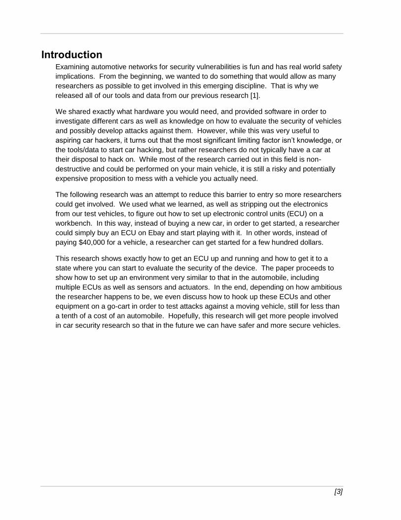
Introduction Examining automotive networks for security vulnerabilities is fun and has real world safety
implications. From the beginning, we wanted to do something that would allow as many
researchers as possible to get involved in this emerging discipline. That is why we
released all of our tools and data from our previous research [1].
We shared exactly what hardware you would need, and provided software in order to
investigate different cars as well as knowledge on how to evaluate the security of vehicles
and possibly develop attacks against them. However, while this was very useful to
aspiring car hackers, it turns out that the most significant limiting factor isn’t knowledge, or
the tools/data to start car hacking, but rather researchers do not typically have a car at
their disposal to hack on. While most of the research carried out in this field is non-
destructive and could be performed on your main vehicle, it is still a risky and potentially
expensive proposition to mess with a vehicle you actually need.
The following research was an attempt to reduce this barrier to entry so more researchers
could get involved. We used what we learned, as well as stripping out the electronics
from our test vehicles, to figure out how to set up electronic control units (ECU) on a
workbench. In this way, instead of buying a new car, in order to get started, a researcher
could simply buy an ECU on Ebay and start playing with it. In other words, instead of
paying $40,000 for a vehicle, a researcher can get started for a few hundred dollars.
This research shows exactly how to get an ECU up and running and how to get it to a
state where you can start to evaluate the security of the device. The paper proceeds to
show how to set up an environment very similar to that in the automobile, including
multiple ECUs as well as sensors and actuators. In the end, depending on how ambitious
the researcher happens to be, we even discuss how to hook up these ECUs and other
equipment on a go-cart in order to test attacks against a moving vehicle, still for less than
a tenth of a cost of an automobile. Hopefully, this research will get more people involved
in car security research so that in the future we can have safer and more secure vehicles.
[4]
Putting ECUs on the Bench The main contribution of this paper is in how to get one or more ECUs working on a
workbench without having to buy a vehicle. Doing so requires some rudimentary
electrical knowledge, comprehension of automotive systems, and a basic understanding
of the Controller Area Network (CAN) protocol.
Capture Traffic from a CAN Bus You’ll want to obtain a number of CAN bus traffic captures, especially if you don’t own the
vehicle and only have temporary access to it. Think of every conceivable situation you
may be in: idling, driving, going in reverse, auto-parking, using cruise control, etc.
Captures may be taken via the ODB-II port or directly from the CAN lines using an ECOM
cable and EcomCat, discussed in our previous paper [1]. No matter how careful you are,
you’ll later wish you had more captures.
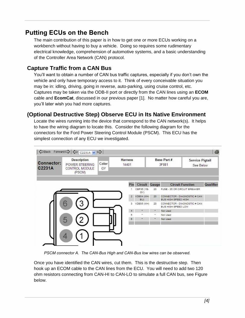
(Optional Destructive Step) Observe ECU in Its Native Environment Locate the wires running into the device that correspond to the CAN network(s). It helps
to have the wiring diagram to locate this. Consider the following diagram for the
connectors for the Ford Power Steering Control Module (PSCM). This ECU has the
simplest connection of any ECU we investigated.
PSCM connector A. The CAN-Bus High and CAN-Bus low wires can be observed.
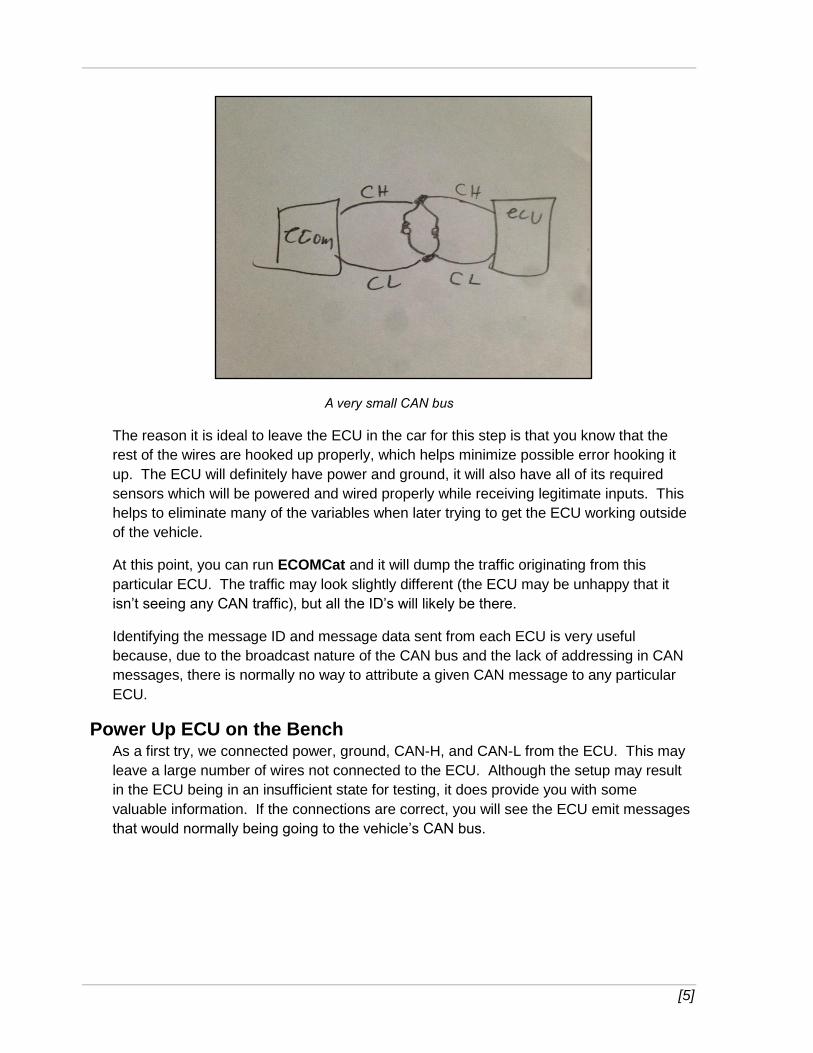
Once you have identified the CAN wires, cut them. This is the destructive step. Then
hook up an ECOM cable to the CAN lines from the ECU. You will need to add two 120
ohm resistors connecting from CAN-HI to CAN-LO to simulate a full CAN bus, see Figure
below.
[5]
A very small CAN bus
The reason it is ideal to leave the ECU in the car for this step is that you know that the
rest of the wires are hooked up properly, which helps minimize possible error hooking it
up. The ECU will definitely have power and ground, it will also have all of its required
sensors which will be powered and wired properly while receiving legitimate inputs. This
helps to eliminate many of the variables when later trying to get the ECU working outside
of the vehicle.
At this point, you can run ECOMCat and it will dump the traffic originating from this
particular ECU. The traffic may look slightly different (the ECU may be unhappy that it
isn’t seeing any CAN traffic), but all the ID’s will likely be there.
Identifying the message ID and message data sent from each ECU is very useful
because, due to the broadcast nature of the CAN bus and the lack of addressing in CAN
messages, there is normally no way to attribute a given CAN message to any particular
ECU.
Power Up ECU on the Bench As a first try, we connected power, ground, CAN-H, and CAN-L from the ECU. This may
leave a large number of wires not connected to the ECU. Although the setup may result
in the ECU being in an insufficient state for testing, it does provide you with some
valuable information. If the connections are correct, you will see the ECU emit messages
that would normally being going to the vehicle’s CAN bus.
[6]
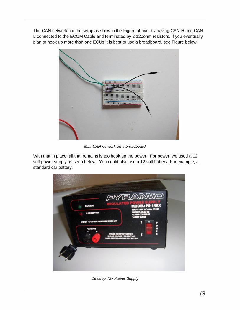
The CAN network can be setup as show in the Figure above, by having CAN-H and CAN-
L connected to the ECOM Cable and terminated by 2 120ohm resistors. If you eventually
plan to hook up more than one ECUs it is best to use a breadboard, see Figure below.
Mini-CAN network on a breadboard
With that in place, all that remains is too hook up the power. For power, we used a 12
volt power supply as seen below. You could also use a 12 volt battery. For example, a
standard car battery.
Desktop 12v Power Supply

[7]
Hook up the positive (+) output to anywhere that the wiring diagram says power, fuse, or
potentially ignition. Hook up the negative (-) output to anywhere that the wiring diagram
says ground. Again, if you plan to hook up multiple ECUs, you may wish to run the power
supply through a bread board to make it easier to power the multiple devices.
Also, in very rare circumstances, there may be an input that you shouldn’t hook up. For
example, in the Ford ACM/APIM, there is one wire that supplies power only when the car
is being cranked. This is so the radio doesn’t play during that time so the engine can get
as much power as it needs. However, if you blindly supply power to that wire, the radio
won’t play, which can be frustrating!
Normally, an ECU will not indicate in any way that it is powered and/or working properly
(or not). In some circumstances, a light may light up or it may make sound, which is very
helpful. However, in most cases, without further investigation, there is no way to tell if
you’ve wired it up properly. Worse, there isn’t an easy way to figure out what you did
wrong if it isn’t set up properly, see a later section on troubleshooting ECU bench setup
for more details.
The best way to tell if the ECU is working is to run ECOMCat with Ecom cable on the
device. You should see network traffic. You should also be able to talk to the ECU with
diagnostic packets. With this simple setup, you can begin to work on problems like
figuring out what types of protocols the ECU understands, getting security access to the
ECU, figuring out if it supports features like RoutineControl, etc. However, the ECU may
not be fully functional so it may be possible that it supports more features than it lets on at
the beginning. Additionally, the ECU may seem perfectly functional, but it is not. This is
one of the pitfalls of working on an ECU in a make-shift test environment outside the
vehicle.
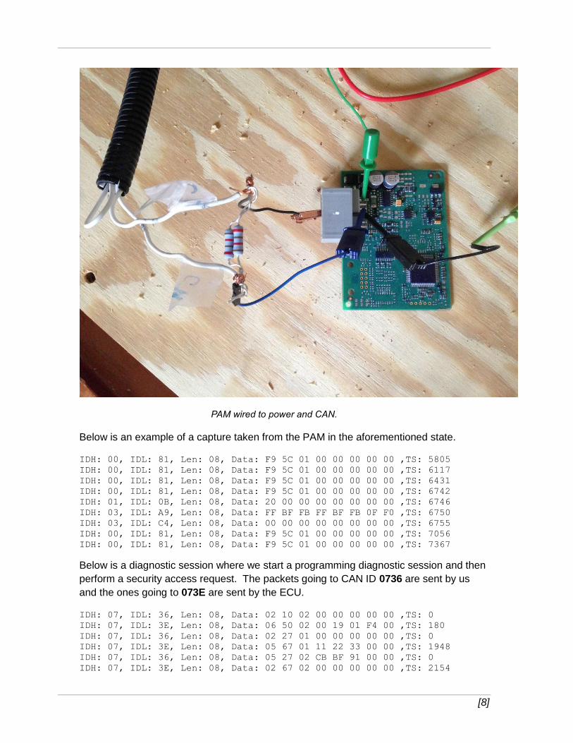
The whole setup for the Ford Parking Assist Module (PAM) is shown below. Only 4 wires
are actually connected to the ECU, as described above. In an actual automobile, 16
wires would be connected in total. The wiring diagram for the connector is shown in the
next section.
[8]
PAM wired to power and CAN.
Below is an example of a capture taken from the PAM in the aforementioned state.
IDH: 00, IDL: 81, Len: 08, Data: F9 5C 01 00 00 00 00 00 ,TS: 5805
IDH: 00, IDL: 81, Len: 08, Data: F9 5C 01 00 00 00 00 00 ,TS: 6117
IDH: 00, IDL: 81, Len: 08, Data: F9 5C 01 00 00 00 00 00 ,TS: 6431
IDH: 00, IDL: 81, Len: 08, Data: F9 5C 01 00 00 00 00 00 ,TS: 6742
IDH: 01, IDL: 0B, Len: 08, Data: 20 00 00 00 00 00 00 00 ,TS: 6746
IDH: 03, IDL: A9, Len: 08, Data: FF BF FB FF BF FB 0F F0 ,TS: 6750
IDH: 03, IDL: C4, Len: 08, Data: 00 00 00 00 00 00 00 00 ,TS: 6755
IDH: 00, IDL: 81, Len: 08, Data: F9 5C 01 00 00 00 00 00 ,TS: 7056
IDH: 00, IDL: 81, Len: 08, Data: F9 5C 01 00 00 00 00 00 ,TS: 7367
Below is a diagnostic session where we start a programming diagnostic session and then
perform a security access request. The packets going to CAN ID 0736 are sent by us
and the ones going to 073E are sent by the ECU.
IDH: 07, IDL: 36, Len: 08, Data: 02 10 02 00 00 00 00 00 ,TS: 0
IDH: 07, IDL: 3E, Len: 08, Data: 06 50 02 00 19 01 F4 00 ,TS: 180
IDH: 07, IDL: 36, Len: 08, Data: 02 27 01 00 00 00 00 00 ,TS: 0
IDH: 07, IDL: 3E, Len: 08, Data: 05 67 01 11 22 33 00 00 ,TS: 1948
IDH: 07, IDL: 36, Len: 08, Data: 05 27 02 CB BF 91 00 00 ,TS: 0
IDH: 07, IDL: 3E, Len: 08, Data: 02 67 02 00 00 00 00 00 ,TS: 2154
[9]
Hook Up Sensors and Actuators Some minor differences emerge when looking at CAN packets captured on the
workbench compared to looking at CAN packets captured from the automobile. Consider
CAN ID 010B. In the real capture it looks like:
IDH: 01, IDL: 0B, Len: 08, Data: 60 00 00 00 00 00 00 00
In the bench ECU it looks like
IDH: 01, IDL: 0B, Len: 08, Data: 20 00 00 00 00 00 00 00 ,TS: 6746
Presumably that first byte is some bit field and a particular bit is not set on the bench.
Some ECUs will not function properly if they are missing some sensors or actuators. In
the case of the PAM, this message is an indication that the ECU is having problems and
knows that its sensors are broken or missing. (This information could also be found by
starting a diagnostic session and reading DTC error codes).
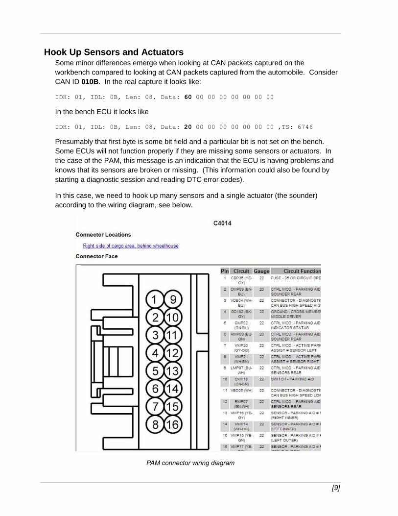
In this case, we need to hook up many sensors and a single actuator (the sounder)
according to the wiring diagram, see below.
PAM connector wiring diagram
[10]
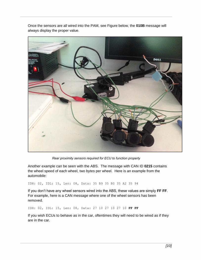
Once the sensors are all wired into the PAM, see Figure below, the 010B message will
always display the proper value.
Rear proximity sensors required for ECU to function properly
Another example can be seen with the ABS. The message with CAN ID 0215 contains
the wheel speed of each wheel, two bytes per wheel. Here is an example from the
automobile:
IDH: 02, IDL: 15, Len: 08, Data: 35 B9 35 B0 35 A2 35 94
If you don’t have any wheel sensors wired into the ABS, these values are simply FF FF.
For example, here is a CAN message where one of the wheel sensors has been
removed.
IDH: 02, IDL: 15, Len: 08, Data: 27 10 27 10 27 10 FF FF
If you wish ECUs to behave as in the car, oftentimes they will need to be wired as if they
are in the car.
[11]
Simulating CAN Traffic from Missing ECUs Even with all the sensors hooked up properly, many ECUs will still not function properly
unless they receive certain messages from the CAN. The easiest way to do this is to take
a valid capture, remove the messages which originate from the ECU(s) on the bench, and
then replay the packets using EcomCat.
In the PAM example, the ECU will not activate the proximity sensors unless it thinks the
car is in reverse. If you replay a packet capture of the car in reverse, the sensors will
begin to work and it will begin to emit warning sounds if something is near the sensor.
Also, message with CAN ID 03A9 will begin to show the sensor data.
IDH: 03, IDL: A9, Len: 08, Data: 09 B0 95 FF BF FB 09 50 ,TS: 418839
IDH: 03, IDL: A9, Len: 08, Data: 09 B0 93 FF BF FB 09 30 ,TS: 419616
IDH: 03, IDL: A9, Len: 08, Data: 09 90 8F FF BF FB 08 F0 ,TS: 421978
...
Other examples of needing to send CAN traffic include the Ford PSCM. As you saw
before, from a wiring perspective, it is the simplest ECU to hook up. In only has power,
ground, and CAN. It has no outside sensors or actuators. Of course, internally, it has
both a steering wheel position sensor and a motor to turn the steering wheel. However, if
you wire it up and don’t send it CAN messages, the actual power steering won’t work.
That is, if you turn the steering wheel, the internal motor won’t assist you, but as soon as
you begin to replay CAN traffic to it, it makes a loud click and then it will help turn the
wheel.
Similarly, the ABS will make a loud click when you first send traffic. The audio control
module (ACM) won’t even power up the screen unless it is continuously receiving CAN-
MS Bus traffic.
Configuring Modules Some ECUs, if you buy them new, and possibly if you buy them used, will need to be
configured for the vehicle that you are telling it that it belongs to. For example, sensors
may needed to be configured, or the ECU may need to be programmed (with the VIN
from the vehicle, for example). All of these tasks can be accomplished with the
automotive tool available from the manufacturer.
As an example, the Ford PSCM can be purchased directly from Ford. However, if you
follow the above procedures and wire it up to power and CAN, and send it messages, it
never works properly. For example, the sixth byte of the message with CAN ID 0080
seems to indicate the state of the ECU. Normally, this byte starts at 80 and quickly
moves to C0 and later, once the wheel has been turned sufficiently far to the left and
right, C3.
IDH: 00, IDL: 80, Len: 08, Data: FF FC FF FF 01 80 00 FF ,TS: 32552
IDH: 00, IDL: 80, Len: 08, Data: FF FC 4E 20 01 C0 01 FF ,TS: 32708
IDH: 00, IDL: 80, Len: 08, Data: FF FC 4E 20 01 C0 02 FF ,TS: 32865
IDH: 00, IDL: 80, Len: 08, Data: FF FC 4E 20 01 C0 03 FF ,TS: 33021
[12]
Once the sixth byte reaches C3, the first two bytes begin indicating the steering wheel
position, see below.
IDH: 00, IDL: 80, Len: 08, Data: 4E 1D 4E 2F 01 C3 40 FF ,TS: 127646
IDH: 00, IDL: 80, Len: 08, Data: 4E 1D 4E 2F 01 C3 41 FF ,TS: 127802
IDH: 00, IDL: 80, Len: 08, Data: 4E 21 4E 31 01 C3 42 FF ,TS: 127958
IDH: 00, IDL: 80, Len: 08, Data: 4E 21 4E 31 01 C3 44 FF ,TS: 128114
IDH: 00, IDL: 80, Len: 08, Data: 4E 21 4E 34 01 C3 45 FF ,TS: 128271
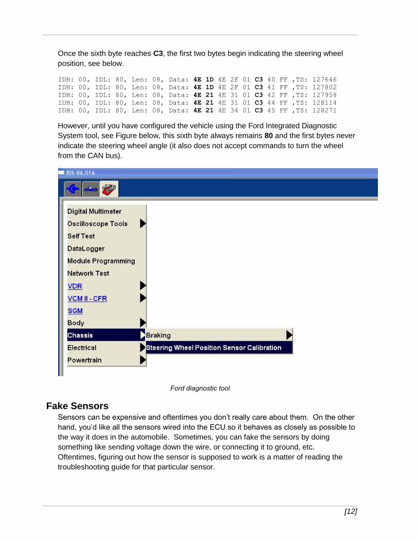
However, until you have configured the vehicle using the Ford Integrated Diagnostic
System tool, see Figure below, this sixth byte always remains 80 and the first bytes never
indicate the steering wheel angle (it also does not accept commands to turn the wheel
from the CAN bus).
Ford diagnostic tool
Fake Sensors Sensors can be expensive and oftentimes you don’t really care about them. On the other
hand, you’d like all the sensors wired into the ECU so it behaves as closely as possible to
the way it does in the automobile. Sometimes, you can fake the sensors by doing
something like sending voltage down the wire, or connecting it to ground, etc.
Oftentimes, figuring out how the sensor is supposed to work is a matter of reading the
troubleshooting guide for that particular sensor.
[13]
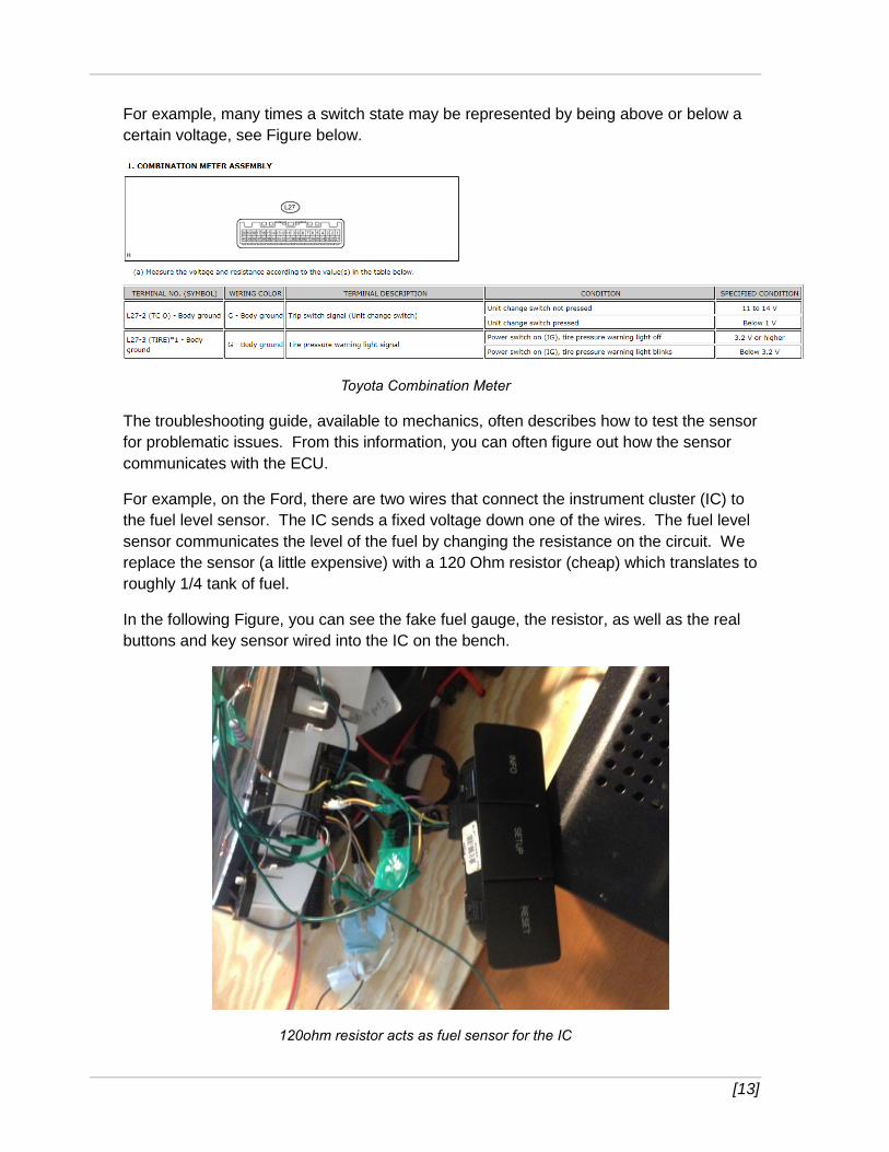
For example, many times a switch state may be represented by being above or below a
certain voltage, see Figure below.
Toyota Combination Meter
The troubleshooting guide, available to mechanics, often describes how to test the sensor
for problematic issues. From this information, you can often figure out how the sensor
communicates with the ECU.
For example, on the Ford, there are two wires that connect the instrument cluster (IC) to
the fuel level sensor. The IC sends a fixed voltage down one of the wires. The fuel level
sensor communicates the level of the fuel by changing the resistance on the circuit. We
replace the sensor (a little expensive) with a 120 Ohm resistor (cheap) which translates to
roughly 1/4 tank of fuel.
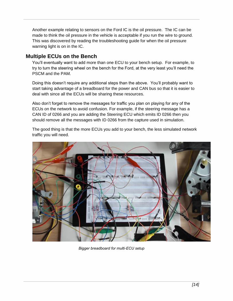
In the following Figure, you can see the fake fuel gauge, the resistor, as well as the real
buttons and key sensor wired into the IC on the bench.
120ohm resistor acts as fuel sensor for the IC
[14]
Another example relating to sensors on the Ford IC is the oil pressure. The IC can be
made to think the oil pressure in the vehicle is acceptable if you run the wire to ground.
This was discovered by reading the troubleshooting guide for when the oil pressure
warning light is on in the IC.
Multiple ECUs on the Bench You’ll eventually want to add more than one ECU to your bench setup. For example, to
try to turn the steering wheel on the bench for the Ford, at the very least you’ll need the
PSCM and the PAM.
Doing this doesn’t require any additional steps than the above. You’ll probably want to
start taking advantage of a breadboard for the power and CAN bus so that it is easier to
deal with since all the ECUs will be sharing these resources.
Also don’t forget to remove the messages for traffic you plan on playing for any of the
ECUs on the network to avoid confusion. For example, if the steering message has a
CAN ID of 0266 and you are adding the Steering ECU which emits ID 0266 then you
should remove all the messages with ID 0266 from the capture used in simulation.
The good thing is that the more ECUs you add to your bench, the less simulated network
traffic you will need.
Bigger breadboard for multi-ECU setup
[15]
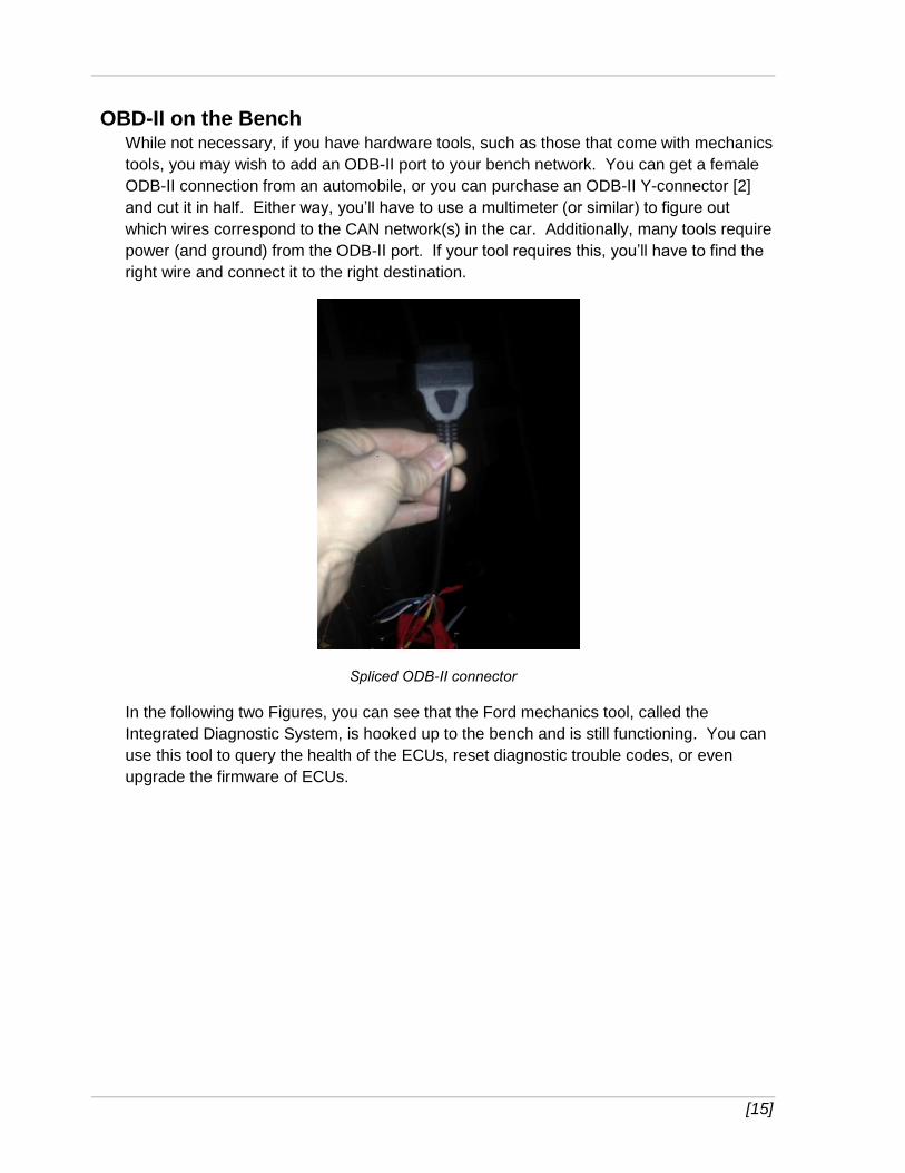
OBD-II on the Bench While not necessary, if you have hardware tools, such as those that come with mechanics
tools, you may wish to add an ODB-II port to your bench network. You can get a female
ODB-II connection from an automobile, or you can purchase an ODB-II Y-connector [2]
and cut it in half. Either way, you’ll have to use a multimeter (or similar) to figure out
which wires correspond to the CAN network(s) in the car. Additionally, many tools require
power (and ground) from the ODB-II port. If your tool requires this, you’ll have to find the
right wire and connect it to the right destination.
Spliced ODB-II connector
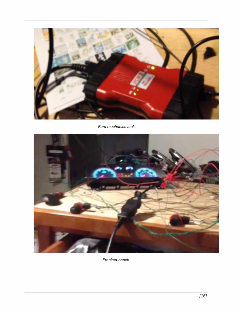
In the following two Figures, you can see that the Ford mechanics tool, called the
Integrated Diagnostic System, is hooked up to the bench and is still functioning. You can
use this tool to query the health of the ECUs, reset diagnostic trouble codes, or even
upgrade the firmware of ECUs.
[16]
Ford mechanics tool
Franken-bench
[17]
Troubleshooting Issues Many times you’ll wire up an ECU, power it up, and nothing comes out of the CAN lines.
This is tough as there isn’t an easy way to tell what is happening. This is when you’ll
really miss software exploit development! Some things to check include:
Power/ground connected to the right pins. You can check that power is really coming here with a mulitmeter. If you have the board out, and understand it, you can check for power further on in the board to make sure that you have it wired to the correct pins.
Another common error is having CAN wires hooked to incorrect pins. Also, make sure you have the resistors on the network. Shorts are also commonplace. Many times we saw smoke which led to us finding two wires touching that weren’t supposed to be!
One quick conclusion to jump to when troubleshooting is that the ECU is bricked/fried.
However, in all of our testing and all the times we wired it up wrong, we never once fried
an ECU. Even when mistaking CAN-H for Power (+). They seem very resilient and tough
to ruin. If the ECU is not running, the odds are it is wired incorrectly.
[18]
Testing on the Bench By this point, you should have an ECU, or possibly a network of ECUs set up on the
workbench, along with enough sensors/actuators and network traffic captures to make
them all relatively happy. This is your testing environment. But what can you test here,
and more importantly, what can’t you test here that you could in a real car?
ECU Isolation
In the earliest steps above, you hooked an ECOM cable to a single ECU. This is the best
way to find out which CAN messages an ECU sends out. Remember, by just looking at
CAN traffic, you cannot determine which ECUs are sending which messages. This is a
huge step in decoding CAN network traffic as it is broadcast in nature and doesn’t have
any source (or destination) addressing.
By isolating each ECU and observing the messages sent, you can determine which ECU
sends which messages for every ID seen on the CAN bus. This can really help in reverse
engineering the meaning of each message. For example, a CAN message from the ABS
system won’t have anything to do with the steering angle or gear of the car. Likewise, if
you are looking for a message that has to do with making the steering wheel turn, there is
a good chance it originates from the PAM. Also, some ECUs, like the Prius’ Seat Belt
ECU, only send out a couple of messages which make identifying their purpose rather
simple.
While it is possible that some ECUs may not send out all possible messages on the
bench that they would in the real car (since they may not have all their sensors or be
seeing all the traffic they expect), in practice, for both of our cars and for each ECU we
tested, they always sent out every message on the bench that they did in the car.
ECU Interrogation and Flashing Beyond just passively observing CAN traffic, the best part of having the ECUs working is
that you can interact with them. This includes the ability to perform security access or
similar authentication schemes. You could attempt brute force or use the mechanics
tools and reverse engineer the tools to extract keys and try them out on the bench.
You can also try other standardized commands such as RoutineControl,
ReadMemoryByAddress, etc. In this regard, the ECU will behave as if it is in the
automobile, only you can do it from your desk instead of hauling all of your stuff out to
your uncomfortable garage or even owning the vehicle!
Finally, you can observe firmware flashing by the mechanics tools and figure out how to
do it yourself.
For more details on all of this, please see our previous whitepaper, “Adventures in
Automotive Networks and Control Units” [1]. The current paper is not written to show you
how to work with ECUs, but rather how to set them up on a workbench so you can work
with them.
[19]
ECU Sensor Readings Once you have working ECUs, and know which messages are coming from each, you
may notice that some CAN messages contain sensor readings. This is helpful for reverse
engineering the data that the messages contain and also for selecting possible targets for
message injection (see next section).
Previous sections showed messages that indicated wheel speed sensor readings as well
as steering wheel position sensor readings. Another example from earlier in the paper
showed rear wheel proximity sensors displayed in a CAN message.
If we would have isolated the Toyota Parking Assist ECU and Power Steering ECU in our
previous research, it would have taken much less time to identify, understand, and
manipulate messages to control the steering of the Toyota Prius.
Attacks – CAN Message Injection Many of the attacks outlined in our previous paper [1] are possible on the ECUs setup on
the bench, in one form or another. These attacks were all carried out by injecting CAN
messages onto the proper CAN bus. Messages can be injected onto the bench CAN bus
as well.
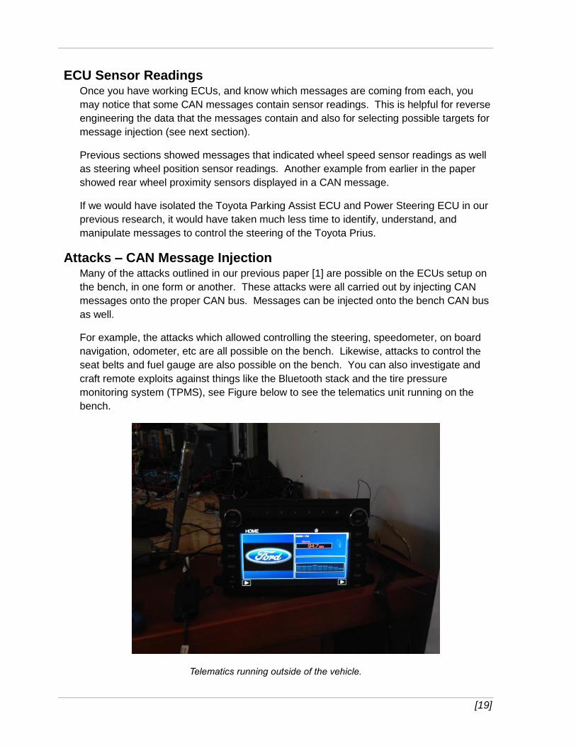
For example, the attacks which allowed controlling the steering, speedometer, on board
navigation, odometer, etc are all possible on the bench. Likewise, attacks to control the
seat belts and fuel gauge are also possible on the bench. You can also investigate and
craft remote exploits against things like the Bluetooth stack and the tire pressure
monitoring system (TPMS), see Figure below to see the telematics unit running on the
bench.
Telematics running outside of the vehicle.
[20]
Another set of attacks is possible in theory, but you may not have the correct
sensors/actuators to tell. While it is possible to send messages to lock the doors or blow
the horn, unless you have those accessories wired into your bench environment, you
won’t be able to evaluate whether they worked or not. The bench setup does provide a
great test bed to perform work in the comfort of your lab before testing in a vehicle
(Assuming you live in Pittsburgh/St. Louis and it is very cold in the winter).
Attacks that rely on having a complete sub-system that is difficult to remove from the
vehicle consist of a final set of attacks that are possible but difficult to evaluate on the
bench. For example, consider attacks against the braking system. Specifically, on the
Ford, there were two separate attacks against the ABS ECU. One locked the brakes
while another bled the brakes (causing them not to stop the vehicle during the process).
You can carry out both of these attacks against the ABS on the bench. However, since
you likely don’t have the actual brakes on the bench, it’s hard to tell what is going on. For
the one where the brakes lock, you can only hear the ABS make a humming sound. For
the bleeding the brakes attack, you can hear the ABS make a loud pumping sound and if
there is any residual liquid inside the ABS ECU, it will pump it out. Either way, you
basically know you did something, but you don’t necessarily know if it was dangerous to a
driver.
Limitations Working on a CAN network on a workbench certainly has its advantages, such as cost
and convenience. However, there are some significant drawbacks. No matter how
accurate you try to make your artificial bench environment, you’ll be missing some ECUs,
sensors/actuators, or some traffic or something (unless you’re a manufacturer who has a
professional bench setup).
It won’t be a perfect copy. For these reasons, some ECUs may not act exactly as they
would in the vehicle. This can work both ways. You may send traffic to the ECU that
won’t affect it on the bench but would have done something interesting in the car, since
perhaps the ECU is not in the right state to receive these messages. Likewise, you may
think you found a great attack against an ECU when in the car it fails to work, perhaps
because of a safety feature around speed or gear of the vehicle.
A great example of this is steering using the Toyota’s Lane Keep Assist (LKA) feature on
the bench. Without the steering angle ECU reporting the angle (and a simulated angle of
‘straight ahead’), the LKA messages could be used to turn the wheel without the angle
limitations adhered to in the car. The LKA scenario is interesting for two reasons. First,
you might have thought you had a great attack that worked on the bench, but would not
work properly in the car, due to angle turning limitations. Secondly, you could alter your
attack in the car to always report ‘straight ahead’ as the steering angle in addition to the
LKA messages.
Another drawback is without a moving vehicle, it may be hard to carry out or evaluate
attacks. For example, on the bench it will be hard to simulate the necessary data to the

[21]
sensors in order to convince the ECU it is about to run into something (Pre-Collision
System), while in an actual car you can simply run into something to get this data. As in
the example of the ABS ECU given above, it may also be hard to tell exactly how
dangerous a particular attack may be if you aren’t actually moving in a car.
The ultimate test of the successful car hack is against an actual car, not the bench. The
bench only serves as a cost-effective, convenient way to develop attacks.
[22]
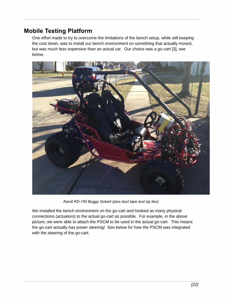
Mobile Testing Platform One effort made to try to overcome the limitations of the bench setup, while still keeping
the cost down, was to install our bench environment on something that actually moved,
but was much less expensive than an actual car. Our choice was a go-cart [3], see
below.
Kandi KD-150 Buggy Gokart (plus duct tape and zip ties)
We installed the bench environment on the go-cart and hooked as many physical
connections (actuators) to the actual go-cart as possible. For example, in the above
picture, we were able to attach the PSCM to be used in the actual go-cart. This means
the go-cart actually has power steering! See below for how the PSCM was integrated
with the steering of the go-cart.
[23]
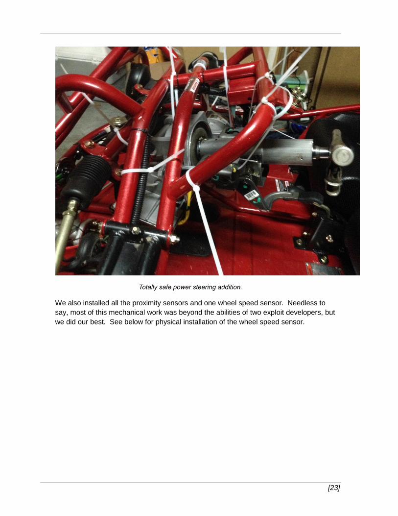
Totally safe power steering addition.
We also installed all the proximity sensors and one wheel speed sensor. Needless to
say, most of this mechanical work was beyond the abilities of two exploit developers, but
we did our best. See below for physical installation of the wheel speed sensor.
[24]
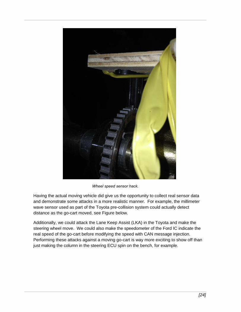
Wheel speed sensor hack.
Having the actual moving vehicle did give us the opportunity to collect real sensor data
and demonstrate some attacks in a more realistic manner. For example, the millimeter
wave sensor used as part of the Toyota pre-collision system could actually detect
distance as the go-cart moved, see Figure below.
Additionally, we could attack the Lane Keep Assist (LKA) in the Toyota and make the
steering wheel move. We could also make the speedometer of the Ford IC indicate the
real speed of the go-cart before modifying the speed with CAN message injection.
Performing these attacks against a moving go-cart is way more exciting to show off than
just making the column in the steering ECU spin on the bench, for example.
[25]
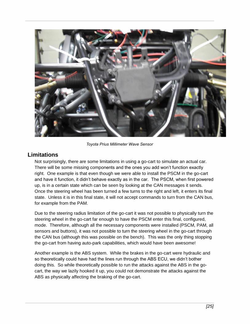
Toyota Prius Millimeter Wave Sensor
Limitations Not surprisingly, there are some limitations in using a go-cart to simulate an actual car.
There will be some missing components and the ones you add won’t function exactly
right. One example is that even though we were able to install the PSCM in the go-cart
and have it function, it didn’t behave exactly as in the car. The PSCM, when first powered
up, is in a certain state which can be seen by looking at the CAN messages it sends.
Once the steering wheel has been turned a few turns to the right and left, it enters its final
state. Unless it is in this final state, it will not accept commands to turn from the CAN bus,
for example from the PAM.
Due to the steering radius limitation of the go-cart it was not possible to physically turn the
steering wheel in the go-cart far enough to have the PSCM enter this final, configured,
mode. Therefore, although all the necessary components were installed (PSCM, PAM, all
sensors and buttons), it was not possible to turn the steering wheel in the go-cart through
the CAN bus (although this was possible on the bench). This was the only thing stopping
the go-cart from having auto-park capabilities, which would have been awesome!
Another example is the ABS system. While the brakes in the go-cart were hydraulic and
so theoretically could have had the lines run through the ABS ECU, we didn’t bother
doing this. So while theoretically possible to run the attacks against the ABS in the go-
cart, the way we lazily hooked it up, you could not demonstrate the attacks against the
ABS as physically affecting the braking of the go-cart.
[26]
Lastly, certain pieces did not fit together, not so shockingly. The steering column
connector from the Toyota Prius was too large to fit around the steering column connector
for the go-cart, therefore while the power steering unit and corresponding column were
installed and controllable from the CAN bus, it was not directly linked to the go-cart. Had
we any welding / machine-shop capabilities we are confident that would could have
gotten LKA working in the go-cart.
Conclusion Our previous research [1] showed that physical attributes of the automobile could be
controlled with messages sent across the CAN bus, whether normal or diagnostic. We still
felt that to get offensive minded security researchers involved in main stream automotive
security research the cost of entry had to be lowered. Therefore, in this paper, we
provided techniques that allowed testing certain features of an automobile without a
vehicle. Additionally, even if car-like mobility is required, a cost effective platform, in the
form of a go-cart, can be purchased to oblige the computer in the vehicle for testing. We
hope that by showing our successes and failures we can entice more security
researchers to investigate issues and help venders create more secure automobiles for
all of us.
References [1] http://blog.ioactive.com/2013/08/car-hacking-content.html [2] http://www.amazon.com/OBDII-Splitter-J1962M-2-J1962F-
145802/dp/B000TMCX72 [3] http://gokartsusa.com/kandi-150-kd-150fs-buggy-gokart.aspx
About IOActive
IOActive is a comprehensive, high-end information security services firm with a long and established pedigree in
delivering elite security services to its customers. Our world-renowned consulting and research teams deliver a
portfolio of specialist security services ranging from penetration testing and application code assessment through to
semiconductor reverse engineering. Global 500 companies across every industry continue to trust IOActive with their
most critical and sensitive security issues. Founded in 1998, IOActive is headquartered in Seattle, USA, with global
operations through the Americas, EMEA and Asia Pac regions. Visit www.ioactive.com for more information. Read the
IOActive Labs Research Blog: http://blog.ioactive.com/. Follow IOActive on Twitter: http://twitter.com/ioactive.