Capt. G. Consorti
167
Ca pt. G. Con 1 nsorti 1
Transcript of Capt. G. Consorti

Capt. G. Con
1
nsorti
1

2
Scope
This Booklet is intended to give basic knowledge to Marine Logistic Personnel to be active part in planning deep water drilling projects. It may help to prevent financial losses by understanding timing and necessities of a Drilling Rig entering in a Company’s Prospect Area.
The content illustrates the early gathering of site and environmental information, helps selecting the right equipment, describes the sequence of the operations and the correct allocation of responsibilities: all these elements are of paramount importance for a smooth start up and a safe completion of the marine aspects of project.
There is nothing new in this little work, only what available in Internet as wording and illustrations, bonded together and validated by the personal experience in organizing and directing offshore marine operations in the oil industry.
G. Consorti

3
INDEX
Definitions 6 CHAPTER 1 – Anchors Anchors in Seafaring and Offshore Industry 11 Brief History in Anchors Evolution 12 Anchor’s Holding Capacity 13 The ultimate Holding capacity 15 Criteria of a good anchor design 15 Soil consistency and strength 15 Variable angle anchors 17 Anchor’s behavior in different soil 18 Drag embed anchors 19 Modern non conventional anchors 20 Different mooring Systems 21 CHAPTER 2 – Moored Rigs Submersible rigs 25 Semi‐submersible rigs 26 Mooring a Semisub ‐ Preparatory 27 Field Info – Sea Bottom Survey – Soil analisys 27 100 Years return site Meteo Study 31 Rig and Vessels positioning Service 32 Mooring analysis 33 Raiser analysis 33 CHATER 3 – Towing Vessels The Dead Weight 35 Bollard pull and bollard pull test 36 Towing Equipment 38 Towing Vessels categories 39 Towing Wires lengths and Minimum Breaking Loads (MBL) 42 Additional Towing Equipment 44 Stability 46 Manning 46 Summary table of requirements for towing vessels 47 Documentation required 49 Recommendations for tests to be approved by Noble Denton 50 CHAPTER 4 – Anchor Handling Vessels AHV Specific Equipments 52

4
AHV Certificates 57 Criteria for selecting the AHV for the Job 57 CHAPTER 5 – Rig Mooring Equipment Semisubs mooring lines 60 Semisubs mooring equipment 61 CHAPTER 6 – Wire Ropes Wire ropes categories 65 Ropes Lays 67 Correct spooling on drums 70 Wire ropes damages 71 Correct/incorrect layering 71 Bulldog Grips 72 CHAPTER 7 ‐ Chains Chains and accessories 73 CHAPTER 8 – Rig Moves Agreed procedures and responsibilities 78 CHAPTER 9 – Anchor Handling Anchor Handling in deep waters 84 The Weather factor 92 Weather Limit 93 CHAPTER 10 – Pre Laid Moorings Pre Laid Moorings 97 Catenary and Taut Pre Laid Moorings 98 Vertical Load Anchors 99 Installation of a Pre Laid line with a DENNLA VLA 100 Example of a Mooring Line Catenary Pre Laid system 103 Example of a Mooring Line Taut Pre Laid system 104 Line equipment specifications in details 106 CHAPTER 11 – Jack Ups Introduction 109 Mat footing and independent Sup Can footing 111 Jack Ups Legs 114 Elevating Systems 114 Operations – from tow to fully elevated 117 Operations – elevated 119

5
Jack Ups design and physic 122 Selected topics on Jack Ups sensitivity 127 Punch Thru 128 CHAPTER 12 – Dynamic Positioning Basic consideration 131 Positioning reference systems and equipment 133 Failure Mode and Effect Analysis (FMEA) 136 Guidelines for design tests and maintenance 137 CHAPTER 13 – The Bourbon Dolphin Case History Forward 138 The Incident 138 Contributory Factors 141 Recommendations 144 CHAPTER 14 – Rig Moves organized Example of an Ocean Rig Moving 146 Rig Move Forms 162 End

6
Definitions
Term or Acronym Definition Accident Event resulting in death, injury or ill health
Adverse weather Adverse weather is defined as being the meteorological andoceanographic conditions which may affect people, equipment or facilities, to such an extent that precautionary measures must be taken to safeguard the facility or to maintain a safe system of work. Adverse weather includes snow, ice, fog, hail, lightning, heavy rain, high winds, low cloud base, poor visibility, extreme water levels, severe sea states and strong currents. In certain circumstances low/no wind can also be adverse weather. Weather conditions can change quickly and the effects of short term variations such as wind gusts must be considered.
Anchor Holding Capacity (AHC)
The AHC is basically the capacity for a given anchor to oppose the forces aimed to disrupt the capability to remain in the same position. It considers only Weight and Efficiency Factor of the anchor, which is related to the design – not the soil.
Approved Bollard Pull The Approved Bollard Pull is the continuous static bollard pull which the Certifying Body is prepared to accept for towing service. Continuous static bollard pull is that obtained by a test at 100% of the Maximum Continuous Rating (MCR) of main engines, averaged over a period of 10 minutes. Where a certificate of Continuous Static Bollard Pull less than 10 years old can be produced, then this will normally be used as the Approved Bollard Pull. Approved Bollard Pull for tugs under 10 years old without a bollard pull certificate may be estimated as 1 tonne /100 (Certified) BHP of the main engines. Approved Bollard Pull for tugs over 10 years old, without a bollard pull certificate less than 10 years old, may be the greater of: the certified value reduced by 1% per year of age since the BP test, or 1 tonne/100 (Certified) BHP reduced by 1% per year of age greater than 10.
Benign area An area which is free of tropical revolving storms and travelling depressions, (but excluding the North Indian Ocean during the southwest monsoon season and the South China Sea during the northeast monsoon season). The specific extent and seasonal limitations of a benign area should be agreed with the Certifying Body office concerned.
Brake Horse Power (BHP)
The measure of horsepower at continuous engine output after the combustion stage.
Charterer The Company or firm that hires the vessel and enters into a contract/charter party with the shipping company/managing company

7
Coastal State Administration
Means the Government of the coastal State which exercisesovereign rights in the area over which a MODU or an OSV is engaged in offshore operations.
Company Oil Company of reference, affiliate or subsidiary companies involvedin a specific operation interested in receiving a performance of a service, in this case connected with Offshore Operations Marine Services.
Continuous Bollard Pull (CBP)
See Approved Bollard Pull (above)
Contractor The organization that has the responsibility for the operation of theservice vessel concerned as laid down in 1.1.2 of the International Safety Management Code.
Customer Affiliate or subsidiary companies participating in a specific operation, who assign the execution of a marine service to third parties, governing such by contract under which they are the final users and beneficiaries.
Dead weight The carrying capacity of a ship, including cargo, bunkers and stores,in metric Tons. Strictly speaking it can be given for any draft, but it is used to indicate summer deadweight at summer draft.
IACS International Association of Classification Societies Incident A marine unserviceability is an occurrence other than a marine
accident, associated with the operation of a ship that jeopardizes or may jeopardize.
Installation Any offshore facility, fixed or floating and any loading system,pipeline or other permanently installed subsea facility.
Logistic Base Coordinator
Means a person based on shore specifically designated by theOperator as a focal point for marine transportation activities. Equivalent to Base Operator Representative.
(Ship) Manager Those responsible for normal vessel management and operation.
Marine Offshore Operation
Any vessel operation conducted offshore
Maximum Bollard Pull (MBP)
The bollard pull obtained by a test, typically at 110% of the Maximum Continuous Rating (MCR) of main engines, over a period of 5 minutes.
Maximum Continuous Rating (MCR)
Manufacturer’s recommended Maximum Continuous Rating of the main engines.
Minimum Breaking Load (MBL)
Certified Minimum Breaking Load of wire rope, chain, stretcher or shackle in tonnes.
Mobile Offshore Installation (MODU)
Means a manned vessel which can be readily relocated and which can perform an industrial function involving offshore operations other than those traditionally provided by vessels covered by Chapter I of the 1974 Solas Convention.
Mobile Offshore Means a manned vessel which can be readily relocated and

8
Drilling Unit (MODU)
which can Perform Drilling Operations at Sea. It is designated to indicate Submersible, Semisubmersible Rigs.
Mobile Offshore Accommodations Units (MOAU)
Means a manned vessel the primary purpose of which is toaccommodate personnel working offshore and subject to registration and classification according to national and/or international maritime regulations. Accommodation units can be self‐propelled or without own propulsion system.
Mobile Offshore Work Unit
Means a manned vessel which may be involved in any single activity or combination of activities such as: ‐ construction, ‐ maintenance (including the maintenance of wells) ‐ lifting operations, ‐ pipe‐laying and related operations, ‐ emergency / contingency preparedness, including fire‐fighting, ‐ offshore production systems, and diving
Noble Denton Consultants Ltd. NDC
The company within the Noble Denton Group operating the Towing Vessel Approvability Scheme (or other Approving Body recognized by Insurance Company of reference).
Operator The Oil Company or its representative which holds the permit area or operates the field where the work is taking place.
Organization Assembly of persons and means, having defined responsibilities,authority and interrelations.
Passenger A passenger is every person other than: a) the master and the members of the crew or other persons
employed or engaged in any capacity on board a ship on the business of that ship
b) a child under one year of age.Redundancy The ability of a component or system to maintain or restore its
function, when a single failure has occurred. Redundancy can be achieved, for instance, by installation of multiple components, systems or alternate means of performing a function.
Safety zone Established within a radius extending to 500 m (meters) beyond theoutline of any installation, excluding submarine pipelines. Any Vessel/Barge wishing to operate within this 500 m (meters) zone must ask the Offshore Installation Manager (OIM) for permission to enter.
Seaworthiness Suitability of a ship to navigate or to be engaged in marine tradingunder conditions of safety.
Ship or Vessel Floating unit suited to be self‐propelled and to operate at sea/lakes/rivers.
Ship Owner The Person/Company who has the property of the vessel.

9
Technical Audit An independent and documented systematic process of attainingevidence that the methods of marine service management and its relevant running are in compliance with foreseen regulations, to be able to objectively assess the measure to which the system has been effectively implemented and is suitable to satisfy Company policy and objectives as concerns health, safety, environment and quality. The word is synonyMODUs and may take the meaning of “assessment”, according to circumstances.
Register The list published from time to time of towing vessels, including all towing vessels entered into the Towing Vessel Approvability Scheme.
SWL Safe Working Load in tonnes. (See also Working Load Limit) Survey Attendance and inspection by a representative. Other surveys which
may be required for a marine operation, including suitability, dimensional, structural, navigational, and Class surveys.
Surveyor An employee of a Contractor or Classification Society performing, for instance, a suitability, dimensional, structural, navigational or Class survey.
Tonnes Metric tonnes of 1,000 kg (approximately 2,204.6 lbs) are used throughout this document. The necessary conversions must be made for equipment rated in long tons (2,240 lbs, approximately 1,016 kg) or short tons (2,000 lbs, approximately 907 kg).
Towing Vessel Approvability Certificate (TVAC)
The document issued by a Classification Society stating that a vessel complied with these guidelines at the time of survey, or was reportedly unchanged at the time of revalidation, in terms of design, construction, equipment and condition, and is considered suitable for use in towing service within the limitations of its Category, bollard pull and any geographical limitations which may be imposed.
Towing Vessel Approvability Scheme (the Scheme)
The scheme whereby owners of vessels may apply to have their vessels surveyed and entered into the Scheme and the Register. The Scheme is administered by Rules, a copy of which may be obtained from International Association of Classification Societies.
Towing Vessel Report The surveyor’s report on which the issue of a TVAC is based.
Ultimate Load Capacity (ULC)
Ultimate load capacity of a wire rope, chain or shackle or similar is the certified minimum breaking load, in tonnes. The load factors allow for good quality splices in wire rope. Ultimate load capacity of a padeye, clench plate, delta plate or similar structure, is defined as the load, in tonnes, which will cause general failure of the structure or its connection into the barge or other structure.
Working Load Limit (WLL)
The maximum static load that the wire, cable or shackle is designed to withstand.

10
Intentionally left blank

11
CHAPTER 1
ANCHORS
1) THE ANCHORS IN SEAFARING AND OFFSHORE INDUSTRY
During centuries of seafaring art, ANCHORS have been the only solution to keep a floater stopped at the sea but free to rotate around a line or chain connecting the anchor to the bow or to stern of the same floater. The anchoring of a floater at sea was mainly for short time and not for the purpose to perform any work from the floater to the sea bottom. From Phoenix, to the Romans, to the Spanish Portuguese Italians English French navigators during the age of the great discoveries up to the first half of the last century, little progress have been made in the design of marine anchors: the anchor’s weight has been always more predominant than the anchor’s shape Here some examples of anchors for Marine use:
When the exploration and production of oil and gas offshore started, a need for more permanent mooring systems became apparent. The design of the anchors was subjected to a dramatic evolution to meet the new tasks: the anchor shape becomes more predominant than the anchor weight. Here some examples of modern anchors for the Offshore use:

12
2) BRIEF HISTORY IN ANCHOR EVOLUTION Most likely at the beginning just a stone connected to a rope was the easiest way to keep a boat in position. Baskets of stone or bags of sand may have been also suitable for the purpose. A solution to the problem was also connecting the line to an asperity of the bottom with a diver. So, the beginning was to count on the mere weight and friction with the sea bottom to allow the floater to remain in position but free to rotate around a single mooring point. With the progress in boatbuilding calling for bigger vessels for the dominion of seas, the use of stones in anchoring a boat became very problematic. The discovery of metals and the introduction of the iron, the same weight in iron start to mean less volume (compared to stones), however the shape of the anchor started to be an important factor in increasing the possibility to keep in position a boat. Easy to find out that the possibility embedding the anchor in the sand or mud could produce additional friction, therefore an increased possibility of holding the boat in position. In the process of the evolution of the anchor design, teeth or flukes were built, allowing the anchor more penetration into the seabed, a shank was placed for better maneuverability and storage, a stabilizer (crossbar) was designed for stability. All these three elements started to be components of typical marine anchors that till now can be seen in any vessel around the world. A large number of anchor types has been designed and commercialized over the years. Some have prospered, others not. The most recent designs are the results of vast experience and extensive testing, and are far more efficient than their historical predecessors. Thru the evolution process, the main component of the anchors has remained the same: the shank, the flukes, the stabilizers Anchor’s parts:
3) THE ANCHORS IN THE OFFSHORE INDUSTRY
The offshore industry has reinvented the anchors giving to them a new shapes and reliability to meet the new challenges. It started a process of modification to ensure the station keeping for long time in waters deeper and deeper and in weather condition up to strong gale forces. In 1946 in Gulf of Mexico the offshore industry start to utilize marine anchors to keep in position a floater with on board a land type of rig. After nearly 60 years of continuous upgrading, the anchor’s shape, technology, resistance has dramatically changed.
13
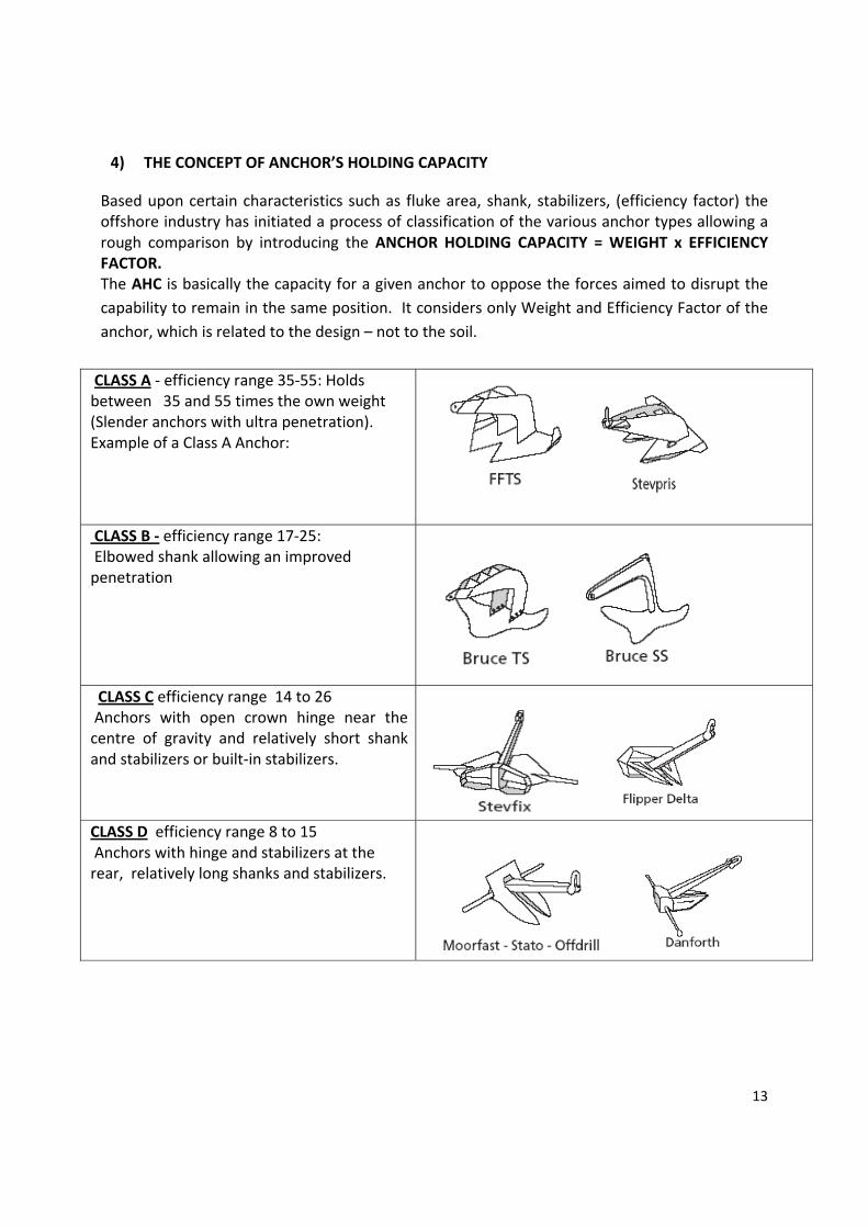
4) THE CONCEPT OF ANCHOR’S HOLDING CAPACITY
Based upon certain characteristics such as fluke area, shank, stabilizers, (efficiency factor) the offshore industry has initiated a process of classification of the various anchor types allowing a rough comparison by introducing the ANCHOR HOLDING CAPACITY = WEIGHT x EFFICIENCY FACTOR. The AHC is basically the capacity for a given anchor to oppose the forces aimed to disrupt the capability to remain in the same position. It considers only Weight and Efficiency Factor of the anchor, which is related to the design – not to the soil.
CLASS A ‐ efficiency range 35‐55: Holds between 35 and 55 times the own weight (Slender anchors with ultra penetration). Example of a Class A Anchor:
CLASS B ‐ efficiency range 17‐25: Elbowed shank allowing an improved penetration
CLASS C efficiency range 14 to 26 Anchors with open crown hinge near the centre of gravity and relatively short shank and stabilizers or built‐in stabilizers.
CLASS D efficiency range 8 to 15 Anchors with hinge and stabilizers at the rear, relatively long shanks and stabilizers.

14
CLASS E efficiency range 8 to 11 anchors with very short, thick stabilizers; hinge at the rear and a relatively short, more or less square‐shaped shank.
CLASS F efficiency range 4 to 6 Anchors having a square shank, without stock stabilizers. The stabilizing resistance is built‐in the crown (Fluke Base).
CLASS G efficiency range <6 Anchors with small fluke area and stabilizers at the front of the shank
The Capacity of an Anchor to hold the position (Anchor Holding Capacity) is negotiated between the following factors:
a) The fluke area The most is the fluke area, the most is the AHC. This shall be negotiated with the anchor design, strength and the acceptable dimension to handled and operated by a given Vessel.
b) The penetration of the anchor The penetration of the anchor is governed by the soil type (deep penetration in very soft clay and shallow penetration in sand), the anchor type (design), the type of mooring line that is used to connect the anchor (chain or wire rope) and the applied load. The streamline in the design of the shape of the shank is important for better penetration. Nowadays the old bulky square single shanks has been replaced by a twin shank construction (for instance Stevpris, FFTS)‐ usually fitted with two thin parallel steel plates, so the soil can easily pass through and consequently can penetrate deeper.
c) The Mooring line An anchor connected to a wire rope mooring line will penetrates deeper than the same anchor connected to a chain mooring line.

15
5) THE ULTIMATE HOLDING CAPACITY
The anchor reaches its Ultimate Holding Capacity (UHC), the moment it will not resist any higher loads and a wedge shaped piece of soil (in front and/or above the anchor) will fail. The holding capacity of the anchor can then be described as a combination of the following parameters:
a. The weight of the anchor b. The weight of the soil in the failure wedge c. The friction of the soil in the failure wedge along fracture lines
d. The friction between fluke surface and soil (fluke area) e. The bearing capacity of shank and mooring line f. The friction of the mooring line
6) CRITERIA FOR GOOD ANCHOR DESIGN
There are several attributes of an anchor which are crucial in assuring its effective performance: • The anchor must offer a high holding capacity; a result of the fluke area and shank design in combination with penetration and soil type. • The design of the anchor should be such that the anchor is capable of being used successfully in all soil conditions encountered over the world, ranging from very soft clay to sand, corals and calcarenites. • The fluke/shank angle of the anchor should be easily adjustable, allowing the anchor to be quickly deployed in different soil conditions. • The design must be so conceived and produced that the high loads common in practice can be resisted and that the anchor can be easily handled, installed, retrieved and stored. • The penetration of an anchor depends upon its shape and design. Obstructing parts on the anchor should be avoided as much as possible. • The stability of an anchor encourages its penetration and, consequently, its holding capacity. Efficient stabilizers are an integral part of a good anchor design. • The shank must permit passage of the soil. 7) SOIL CONSISTENCY AND STRENGHT
Soil consistency/strength is another important factor in delineating the what will be the ultimate anchor holding capacity. The quality of the soil, its weight, its resistance to be penetrated and fracturated will dictate the Ultimate Anchor Holding Capacity Soil strength is generally expressed in terms of the shear strength parameters of the soil. The soil type is classified mainly by grain size distribution.
a) Grain size Soil description: 1. < ‐ 2 µm Clay 2. 2 ‐ 6 µm Fine Silt 3. 6 ‐ 20 µm Medium Silt

16
4. 20 ‐ 60 µm Coarse Silt 5. 60 ‐ 200 µm Fine Sand 6. 200 ‐ 600 µm Medium Sand 7. 0.6 ‐ 2 mm Coarse Sand 8. 2 ‐ 6 mm Fine Gravel 9. 6 ‐ 20 mm Medium Gravel 10. 20 ‐ 60 mm Coarse Gravel 11. 60 ‐ 200 mm Cobbles
‐ 200 mm Boulders
b) Soil classification: On site the values can be estimated from the results of the Standard Penetration Test (SPT) or Cone Penetrometer Test (CPT). This can be usually found in a Sea Bottom Survey and soil analysis that usually the Oil Company carries out before any operational intervention in a given location (Drilling Contractor usually will ask for these parameters BEFORE of any anchoring job). For the sake of clarity and to have a rough idea of what the real consistency of the sea bottom please refer to these easy to remember parameters: • In soft clay the thumb will easily penetrate several inches. • In firm (medium) clay the thumb will penetrate several inches with moderate effort, • Stiff clay will be easily indented with the thumb but penetration will require great effort, • Very stiff clay is easily indented with the thumbnail. • Hard clay is indented with difficulty with the thumbnail.
c) The rock strength can generally be described by its compressive strength. A classification system for soil is based
on the carbonate content and grain.
d) Soil Data: For anchor design and installation, the availability of good soil data is of utmost importance as the soil is of great influence on anchor behavior. The following are influenced by the soil conditions encountered:
Anchor type ‐ some anchors are more suited for soft soil conditions (soft clay), while others are more suited for hard soils (sand and hard clays), although there are a number of anchor types on the market that are suited for most soil conditions encountered.
Holding capacity ‐ in hard soil like sand and hard clay, the maximum attainable ultimate holding capacity with a certain anchor type and size is higher than the attainable ultimate holding capacity in very soft clay.
Penetration and drag ‐ in very soft clay the anchor will penetrate deeper than in harder soil like sand. As a consequence, the drag length of the anchor will also be longer in very soft clay than in hard soil.

17
Retrieval forces ‐ when an anchor is installed in very soft clay, the required retrieval forces (Forces that shall be applied to retrieve the anchor) will be higher than in hard soil like sand. For example, in very soft clay the required retrieval force of an anchor can be equal to 80%‐90% of the installation load while in hard soil (sand) the retrieval force might only be 20%‐30% of the installation load.
8) VARIABLE ANGLE ANCHORS
Drilling Rigs are normally fitted with anchors prone to be effective in most of the soils encountered in the offshore Oil Industry. The penetration of an anchor into a certain soil type is greatly influenced by the selected fluke/shank angle which is the angle between the anchor shackle, the rear of the fluke and the fluke tip, even if not all anchor manufacturers use the same definition. Some of the Last Generation drilling rigs may utilize anchors having the possibility to change this angle according the consistency of the soil of reference. In most of these anchors you may find three (3) settings:
a) First position of 32° Degrees fluke/shank angle suitable in soil such as sand and medium to hard clay, this angle will give the highest holding power.
b) Second position of 50° Degrees fluke/shank angle is appropriate in soft mud
Note: A 32° fluke/shank angle will penetrate less and generate lower holding capacity in soft mud while a 50° angle will be hard to embed in stiff clay: anchor will fail to penetrate into the seabed and will begin to trip, fall aside and slide along the seabed as the following figure explains:
c) Third position of 41° fluke/shank angle setting of 41°, which can be adopted in certain layered soil conditions or intermediate conditions and i.e. where the anchor has to pass through a layer of soft clay before penetrating into a layer of sand
Note: Notwithstanding anchors fabricators declare that angle settings can be changed within half an hour by turning the anchor upside down on the deck of an AHTV, in the reality these operations will cost between up to two days of Rig Time – which is nowadays in the order of 0.75 Million Dollars day.

18
Factors to take in account are the following: Number of anchors to be reset that may be up to 8 The time necessary to deck the anchor, the time necessary to turn the anchor The possibility that the anchor are damaged therefore not easy to remove pins The ability and the willingness of the AHTV crew to perform these operations The time to turn the anchor in the original position
It is recommended a exhaustive discussion between Drilling Contractor, Drilling Department, Marine Contractor to evaluate necessity to perform these angle setting change operation based on a reliable soil analysis, taking in due consideration the fact that a wrong setting of the fluke/shank angle may jeopardize the whole anchoring process. The picture below gives an idea how the different setting of the Shank/Fluke angles affect the travel of the anchor in a given soil (mud): noticeable the different penetration between the two settings at a given force applied and the consequent dimension of the failure wedge above and in front of the anchor that affects the Ultimate Anchor Holding Capacity which is a factor of the total weight of the failure wedge and the capability of the failure wedge to be fractured, which is much higher at the same soil if the wedge is bigger.
9) ANCHOR BEHAVIOUR IN DIFFERENT SOIL ENVIRONMENTS
• In very hard soils, the anchor has to be able to withstand the load with only one or two of the fluke tips buried in the soil, as penetration in very hard soil conditions is generally shallow. • In very soft clays (mud) penetration of the anchor is uncomplicated. However, recovery of the anchor can cause high loads, sometimes exceeding the load that was used to install the anchor. • When using an anchor in very soft clay (mud), the bending moment on the shank is low during the installation and when the anchor is in the soil. However, during the breaking out of the anchor, high bending moments could be introduced in the shank due to the high retrieval forces required in very soft clay. In extremely sticky soils, the breaking out force of the anchor can rise

19
to 80% or 90% of applied anchor load; in certain instances, it can even exceed 100%. To reduce these forces the breaking out procedure is undertaken at low speed to allow time for the anchor to break out. The strength of the fluke and especially the fluke points of an anchor are very important when working in extremely hard soils such as coral, limestone and other rock types. It is possible in such instances that the total holding capacity of the anchor will have to be sustained by the fluke points alone. This means the structure must be strong enough to withstand extreme bending forces. • The loading in normal soil conditions is not a problem due to the fact that the load is equally spread over the fluke. In fig. 2‐14, the different force points are shown for varying soil conditions. The location on the fluke where the proofload is applied, is also indicated. Strength in extremely hard soils In very hard soils such as calcarenite, coral and limestone, an anchor will not penetrate very deeply. Consequently the load applied to the anchor has to be held by the fluke tips of the anchor and a small portion of the fluke. This means that extremely high loads will be applied to the fluke tips, compared to normal soil conditions such as sand and clay.
The loads in a mooring system are caused by the wind, waves and current acting on the floater. Depending on the location of the floater in the world, different metocean conditions will prevail. Some extreme metocean conditions are presented for different areas. The required holding capacity is calculated by applying the factors of safety specified by the classification Societies. Usually the factors of safety for VLAs are higher than the factors of safety required for drag embedment anchors, due to the difference in failure mechanisms. When a drag embedment anchor reaches its ultimate holding capacity, it will continuously drag through the soil without generating additional holding capacity, i.e. the load will stay equal to the UHC. When a VLA exceeds its ultimate pullout capacity, it will slowly be pulled out of the soil. 10) DRAG EMBEDMENT ANCHORS
The drag embedment anchors are anchors that are installed by applying a force which is parallel to the terrain. By applying a load equal to the maximum load that the floater or reference (AHTV, RIG, INSTALLATION VESSEL, SHIP) the anchor penetrates to a certain depth, but will still be capable of further penetration because the ultimate holding capacity has not been reached. The anchor will travel a certain horizontal distance, called the drag length. After the installation, the anchor is capable of resisting loads equal to the installation load without further penetration

20
and drag. When the installation load is exceeded, the anchor will continue to penetrate and drag until the soil is capable of providing sufficient resistance or the ultimate holding capacity has been reached. However, there are certain effects which allow the anchor to withstand forces larger than the installation load, without further penetration and drag ‐ those are:
a) the consolidation effect: which specially clayey soils, keeps in account the fact that the anchor penetration disturbs the soil which temporarily looses its strength, but after a while clay reconsolidates to its initial strength therefore it will take takes a larger load to move the anchor again.
b) the rate effect: An increased rate of loading increases the soil resistance, consequently the anchor holding capacity increases. This must be taken into account with respect to total dynamic loads. For anchor behavior the rate effect factor indicates how much higher the dynamic high frequency load may be without causing extra movement of the anchor once installed at the installation load. Using the rate effect and set‐up factors, the behavior of the anchor after installation can be predicted more accurately.
11) MODERN NON CONVENTIONAL ANCHORS
VLA ‐ BRUCE DENNLA (Drag Embed Near Normal Load Anchor) The vertical load anchor is installed like a conventional drag embedment anchor, but penetrates much deeper. When the anchor mode is changed from the installation mode to the vertical (normal) loading mode, the anchor can withstand both horizontal and vertical loads The 'Vertical' Load Anchor or VLA, which preceded the Dennla, was a special design of drag‐embedment anchor that could be 'triggered' by parting an installation shear pin so that the load line through the centroid of its fluke increased to a final angle of 90º (i.e. normal) to its fluke. When triggered, the VLA provided a holding capacity exceeding twice the pull‐in load but further loading could cause it to pull out of the seabed, a problem that was mitigated but not solved by imposing a higher safety factor on the VLA than on a conventional drag‐embedment anchor. The Dennla Mk4 solves this problem by having a final centroid angle reduced from 90º to 78º ('near normal'), a modification that enables the anchor to continue penetrating after triggering and to do so when pulled at angles at the mud line as high as 45º, a feature important for deepwater applications. At the same depth of embedment as a triggered VLA of equal fluke area, the triggered Dennla has about 90% of the holding capacity of the VLA. However, on loading further, the VLA will pull out whereas the Dennla will continue to embed and generate an increasingly greater holding capacity than that at which the VLA would have failed.
BRUCE DENNLA

21
VLA ‐ Vryhof STEVMANTA The Stevmanta is a Vertical Loaded Anchor that consists of an anchor fluke which is connected with wires to the angle adjuster. The angle adjuster is responsible for changing the anchor from the installation mode to the vertical (or normal) loading mode. There are many options to install VLA anchors.
• Please refer to Vryhof anchor manual for handling and installation .
Suction anchor Like the pile, the suction anchor is a hollow steel pipe, although the diameter of the pipe is much larger than that of the pile. The suction anchor is forced into the seabed by means of a pump connected to the top of the pipe, creating a pressure difference (vacuum). When pressure inside the pipe is lower than outside, the pipe is sucked into the seabed. After installation the pump is removed. The holding capacity of the suction anchor is generated by the friction of the soil along the suction anchor and lateral soil resistance. The suction anchor is capable of withstanding both horizontal and vertical loads
SUCTION PILE ANCHOR
OMNI MAX Torpedo VLA The patented Delmar OMNI‐Max anchor is a gravity‐installed vertically loaded anchor (VLA) that offers characteristics not found in other deepwater anchor foundations. The OMNI‐Max anchor is capable of being loaded in any direction 360° around the axis of the anchor. Under extreme loading and uplift angle conditions, the OMNI‐Max anchor will penetrate deeper into the soil to gain needed capacity. This is a DELMAR Patented anchorage system.
12) DIFFERENT MOORING SYSTEMS
Special projects calling for permanent mooring systems usually utilized by the Oil Industry for FSO, FPSO, LPG plants end others, are normally carried out by specialized Contractors on turn‐key basis. The Logistic Departments of Oil Companies usually are not involved these processes, nevertheless for the sake of pure knowledge we briefly describe few of them:

22
1) CALM BUOY (Catenary Anchor Leg Mooring) Generally the buoy will be moored using four or more mooring lines at equally spaced angles. The mooring lines generally have a centenary shape. The vessel connects to the buoy with a single line and is free to weathervane around the buoy. Since the early days of the offshore industry, the CALM buoy has been a successfully system for importing and exporting of oil. Initially, these buoys were moored in relatively shallow water at near shore locations, often in very harsh wave conditions. In recent years the use of CALM buoys for offloading crude oil from FPSOs in deep water, for example at a number of West of Africa oil fields, is becoming more and more common. Here, the environmental conditions are mild, but the water depth is a complicating factor.
2) SALM BUOY
(Single Anchor Line Mooring ) these types of buoys have a mooring that consists of a single mooring line attached to an anchor point on the seabed, underneath the buoy. The anchor point may be gravity based or piled. Turret mooring type of mooring is generally used on FPSOs and FSOs in more harsh environments. Multiple mooring lines are used, which come together at the turntable built into the FPSO or FSO. The FPSO or FSO is able to rotate around the turret to obtain an optimal orientation relative to the prevailing weather conditions. The Single Anchor Leg Mooring or SALM prevents collision damage to the swivels by placing them underwater and below the keel level of the tanker. Any damage should then only affect the simple surface buoy and be relatively cheap to repair. The underwater swivels do however have maintenance

23
disadvantages. The floating buoy is anchored to the seabed by one single anchor leg, connected to a base type anchor point (ballasted and/ or piled). The buoy can be attached to the base by either one single chain or by a chain or tubular column. The connection between the buoy and the vessel, and between the buoy and the base, can be established in various ways. Fluids flow either through a flexible pipe from the base on the seabed directly to the ship or flow through the base and the tubular column, via a swivel to the ship. The submarine hoses are long enough to adapt to all the motions of the buoy. The fluids are transferred between the buoy and the FPSO through one or more floating hoses. The flow through the buoy goes via a swivel, which allows flow between the geostatic parts and the rotating parts of the buoy.
3) TURRET MOORING A turret mooring system is defined as a mooring system where lines are connected to the turret which via bearings allows the vessel to rotate around the anchor legs. This turret can be MODUnted either internally or externally. An external turret is fixed, with appropriate reinforcements, to bow or stern of the ship. In the internal case the turret is placed within the hull, in a so called moon pool. The chain table, connecting the mooring lines to the turret, can be either above or below Internal permanent turret mooring systems provide FSO/FPSO operators with maximum mooring and fluid transfer capabilities in remote, deepwater and/or harsh environmental conditions. Larger internal systems can accommodate up to 100 or more risers in water depths ranging between 100 to 10,000 feet or more. For locations with severe cyclonic weather and harsh sea conditions, the internal turret mooring system provides

24
full weathervaning and enhanced mooring load capacities that enable the FSO/FPSO to remain permanently on location under the most demanding conditions. Disconnectable systems are applicable in offshore areas of the world subjected to harsh environments and where seasonal cyclonic weather systems or icebergs are predominant. While the turret enables the vessel to freely weathervane in normal to severe conditions, this type of internal system allow the vessel to disconnect to avoid typhoons, hurricanes, icebergs, and other extreme dangerous conditions. The disconnection and reconnection sequence is quick and reliable.

25
CHAPTER 2 MOORED RIGS
1) SUBMERSIBLE RIGS
The submersible drilling platform is supported on large pontoon‐like structures. These pontoons provide buoyancy allowing the unit to be towed from location to location. Once on the location, the pontoon structure is slowly flooded until it rests securely on the bottom floor. The operating deck is elevated above the pontoons on large steel columns to provide clearance above the waves. After the well is drilled, the water is pumped out of the buoyancy tanks and the vessel is re‐floated and towed to the next location. Submersibles, as they are known informally, operate in relatively shallow water, since they must rest on the sea floor.
The first offshore mobile drilling platform was the Hayward‐Barnsdall Breton Rig 20, first operated in 1949 in Louisiana. This rig had evolved from the inland drilling barges which were used to drill in marshes and protected waters in up to 10 feet of water to an offshore use. The Breton Rig 20 was 160 feet by 85 feet, and could work in 20 feet water depth. In 1961, Shell Oil successfully converted an existing submersible rig Blue Water Rig No.1 into the first semi submersible drilling unit for operation in the Gulf of Mexico, starting from an acute observation that while moving the submersible from a location to another at a partial draught, it was found to have good stability and motions whilst being towed. So why not to keep it floating and secure it with anchors? The Semisubmersible was born.
Note: the term Mobile Offshore Drilling Unit (MODU) is generally used for all offshore drilling rigs that can be moved from location to location.
Evolution
Photo: Blue Water Rig No. 1 and Deepsea Delta

26
2) SEMISUBMERSIBLE RIGS A semi‐submersible obtains its buoyancy from ballasted, watertight pontoons located below the ocean surface and wave action. The operating deck can be located high above the sea level due to the good stability of the design and the operating deck is kept well away from the waves. Structural columns are connected to the pontoons and operating deck. With its hull structure submerged at a deep draft (called drilling draft), the semi‐submersible is less affected by wave loadings than a normal ship. With a small water‐plane area, however, the semi‐submersible is sensitive to load changes, and therefore must be carefully trimmed to maintain stability. A semi‐submersible vessel is able to transform from a deep to a shallow draft by deballasting (removing ballast water from the hull), and thereby become a surface vessel (transfer or moving draft). The first purpose built drilling semi‐submersible Ocean Driller was launched in 1963. Since then, many semi‐submersibles have been purpose‐designed for the drilling industry mobile offshore fleet. The industry quickly accepted the semi‐submersible concept and the fleet increased rapidly. The Oil Industry has a common language to catalogue the Semisubmersible Rigs according age built and capability – The term is the Semisub’s GENERATION.
Generation Water Depth Dates
First about 600 ft (200Mt) Early 1960s
Second about 1000 ft (300Mt) 1969–1974
Third about 1500 ft (500Mt) Early 1980s
Fourth about 3000 ft (1000Mt) 1990's
Fifth about 7500 ft (2500Mt) 1998–2004
Sixth about 10000 ft (3000Mt) 2005–2010
The reference in the construction of MODU is the IMO Code for the Construction and Equipment of Mobile Offshore Drilling Units, 2009 (2009 MODU Code). This was adopted by Resolution A.1023(26). The 2009 MODU code updates and revises the Code for the Construction and Equipment of Mobile Offshore Drilling Units, 1989 (1989 MODU Code) was adopted by Assembly resolution A.649(16) and concerns MODUs built since 1 May 1991. The 1989 MODU Code superseded the 1979 MODU Code adopted by Assembly resolution A.414(XI). The Maritime Safety Committee (MSC) adopted amendments to the 1989 MODU Code in May 1991 and decided that, to maintain compatibility with SOLAS, the amendments should become effective on 1 February 1992. Further amendments were adopted in May 1994, to introduce the harmonized system of survey and certification (HSSC) into the Code, provide guidelines for vessels with dynamic positioning systems and introduce provisions for helicopter facilities. The Committee decided that the amendments introducing the HSSC should become effective on the

27
same date as the 1988 SOLAS and Load Line Protocols relating to he HSSC (i.e. 3 February 2000), and that those providing guidelines for vessels with dynamic positioning systems and provisions for helicopter facilities should become effective on 1 July 1994.
3) MOORING A SEMISUBMERSIBLE RIG ‐ PREPARATORY Mooring a Semisubmersible rig is of strategic importance in the offshore industry. In this process the Logistic Departments of Oil Companies are demanded to give the maximum contribution in any moment of the planning and execution in these very costly Drilling Projects. For the accomplishment of the task, a good selection of equipment is of paramount importance. The anchors (of which we have seen some characteristics and behavior in the previous chapter) are just one of the components of the success of the Marine side of a drilling program. Other information and services shall be available in preparing a Drilling Campaign with a MODU. They are:
a. Field info, sea bottom survey and soil analysis b. The 100 years return meteo study c. Rig Positioning System d. Mooring Analysis e. Raiser Analisys
The above information 1 and 2 shall be sent to the Drilling Contractor in due time as they are of utmost importance for the preparation of the Mooring and Riser analysis, to be worked out from their own Engineering Dept. and sent to the Insurance Underwriters for approval. A good Rig Positioning service shall be available before the arrival of the Rig. It will take up to 12 hours to rig up the Positioning equipment on the Rig and Vessels.
• Field Info, Sea Bottom Survey and Soil Analysis
This shall contain: Geographical Coordinates Identification of platform, pipelines, cables, well heads, floating or fixed vessels or any other relevant objects within a 3 mile radius of the proposed location.
bottom anomaly information field bathymetry to a distance at least equivalent to the mooring pattern or more if there are any possibility to drill or re‐spud the well in the vicinity.
Any area‐specific special requirements, such as iceberg avoidance, surface stack operation, large Installation shifts between wells without mooring system redeployment, etc. should be specified to allow due consideration during the mooring design and review processes.
Required or preferred Installation heading. Predominant weather, helicopter and supply vessel operations, communications, etc. may determine the heading.
The water depth at the well, seabed slope, and confirmation of the conditions on the ocean floor constitutes the minimum acceptable information

28
A Sea Bottom Survey and the Soil Analysis and Bathymetry can be attained from a 2D or 3D seismic survey organized by the G&G Dept of the Oil Company aimed mainly to ascertain the potential of a field and the location of the well sites. Normally all the information necessary for anchoring the Semisub may be contained within. Sometimes there are no specific soil investigation inside the Seismic Survey but some data (at least the consistency of the first layers) can be worked out from the geophysical report. The soil conditions report is not mandatory, however, if they are not given, conservative anchor holding and surface casing support assumptions will be used for analysis. A typical soil survey for drag embedment anchor design requires a survey depth of twice the length of the fluke in sand and 8 times the fluke length in very soft clay. In most cases a depth of 8 to 10 meters is sufficient, although in very soft clay a reconnaissance depth of 20 to 30 meters should be considered especially if Vertical Load Anchors are utilized. For optimal drag embedment anchor dimensioning, each anchor location should ideally be surveyed. The soil investigation can consist of bore holes, vibro cores, cone penetration tests or a combination of these. Cone penetration tests including sleeve friction are preferred, but they should be accompanied by at least one vibrocore or sample bore hole per site to obtain a description of the soil. Depending upon the type of survey performed and the soil conditions encountered, the survey report should present the test results obtained on site and in the laboratory including the points as shown in table. Typical contents of a soil survey report:
• AUV Sea Bottom Survey
When there is no necessity of a deep coring of the sea bottom, shall be evaluated the possibility to utilize an AUV (autonoMODUs underwater vehicle). This is very inexpensive compared to the cvharter of a complete Survey Vessel which includes highs costs in mobilization and demobilization. Logistic base must provide a Vessel (Utility) having a (small) crane and the possibility to accommodate 6 technicians for the time necessary for the survey. AUV Is shipped to the base of reference with a crate or container. See drawing below:

29
The system is characterized by: ‐ Compact dimensions (length 3.8m and weight 110kg ) ‐ Modular architecture ‐ Integrated system using stand alone instruments ‐ Capability to perform Bathymetry, SSS and SBP surveys simultaneously ‐ Possibility to work very close to platforms and targets ‐ Capable of 1000 m water depth ‐ Easy to deploy and recover ‐ Good operability in poor weather conditions The AUV system (AutonoMODUs Underwater Vehicle) GAVIA is a modular system that can be configured matching the job requirements; each module, when unused, is kept within a devoted waterproof box. Namely, the lithium battery packs are stored in special cases, designed to protect the batteries and the outer environment The AUV is deployed and recovered by means of a crane (110 kg) and a lars (launch and recovery) system. Lars offers a safer and easier recover of the AUV, its sizes are 2.5m x 2.5m x 3m. At the start of the first mission the AUV ballast needs to be fixed while the equipment is floating, hence a rubber dinghy vessel is needed onboard the vessel. The provision of this small vessel will be at Company’s care. Please see in the following pictures the recovering sequence.

30

31
• AUV Utilization: Track record Contractor GAS (Geological Assistance and Services) has provided AUV sea bottom surveys in different water dept. To estimate the time necessary to perform a survey is function of the duration of the battery package, which is function of the water depth and consequently the duration of each mission. The AUV with the full payload is equipped with 2 batteries to assure 6 hours dive, two replacement batteries are in recharge during each mission, considering the time for downloading the plan is for 2‐3 mission per day. For the sake of statistics:
At 900m water depth the system acquired 14km of lines for mission duration of about 4.5 hours. In addition to the line kilometers it has to be considered that the AUV had run 5km more during the two dives and while reaching the start of the survey.
At 400m water depth the system acquired 21km of lines for mission duration of about 5 hours. In addition to the line kilometers it has to be considered that the AUV had run 2km more during the two dives and while reaching the start of the survey. The mission duration can be estimated ranging between 4.5 and 6 hours. The time needed to replace the battery, to download the data and to prepare the next mission ranges between 1 and 1.5 hours. In this mission the AUV has been operating at about 15m from the seabed granting coverage of about 80m. The optimal spacing between two adjacent lines is 40m. This line spacing minimizes the AUV turning time between one line and the next one but at the same time provides a good data overlap.
• Personnel
Qualified and trained personnel are necessary to obtain maximum efficiency and data reliability. Senior personnel with at least 5 years experience in geophysical survey. Composed by:
1 Party Chief (Senior Geophysics) 2 Engineers (2 senior) for AUV 3 data processor
b) 100 Years Return Meteo Study
The Oil Company (Operator) shall furnish in due time to the Drilling Contractor a Metocean Study containing the information listed below. Company shall request the Study to the Metocean Service Contractor as far in advance before the moving as practically possible, so to allow sufficient time to process all the data necessary to the Drilling Contractor’s Engineering for the project approval by the Underwriters approving bodies. Listed below are the weather information for site evaluation and mooring analysis as per TRANSOCEAN Field Operations Manual which are complete in their request and can be as guidelines for any other Drilling Contractor:
Wind speed ‐ at 10 meter above sea level 1‐hour, 10‐minute, 1‐minute and 3‐ sec. gusts Extreme environmental weather conditions 50 year return period data for the proposed Installation location or the immediate vicinity to be provided. If such return periods are

32
not available the more stringent 100 year return condition should be used for location approval purposes.
Wave height ‐ significant and maximum Wave period ‐ significant and maximum wave energy associated Wave direction Tidal range, tidal streams and currents at 50% of water depth and bottom currents Maximum storm surge Directional information on each item above Predominant swell conditions Hurricane, Monsoon, Typhoon or Ice information Current Omni‐directional, non‐seasonal data is a minimum. Seasonal and directional data should be provided to optimize the mooring system. Since riser analysis is nearly always required, speed and directional profiles to the bottom should be available.
Other eventual for specific location and specific phenomena
c) Rig And Vessels Positioning Services In preparation of a drilling campaign with a Semisubmersible Rig, COMPANY’s Marine Dept shall organize a Rig and Vessels Positioning Service. Both Rig and anchor handling vessels (usually in number of two) are in necessity of a reliable 3rd party Positioning System Equipment that most probably will remain on board the Rig and on board the AHTV for the duration of the campaign, therefore a double rate – operative and stand by – shall be negotiated. The service that COMPANY shall request to CONTRACTOR consist in:
Provide best Positioning Equipment and back up to be positioned on board Rig and Vessels for continuous operation for the duration of the campaign.
Provide best and competent Personnel in teams of 2 or 3 (one or two Operator and Technician) to be positioned on board the Rig.
In detail, Contractor shall provide on board the Semisub Rig a primary and secondary positioning system both with their back‐up, each capable of receiving both GPS and Glonass (Russian System) precise point positioning to decimeter level accuracy minimum of two independent calculation engines that can be configured to use any or weighted combinations of available correction sources each receiver to contain dual GNSS receiver cards and dual antennae and capable of providing a GNSS derived heading reference. Transponders and telemetry equipment must be positioned on the rig and on the AHTV. From the Rig’s post, Positioning Crew must be able to control with pin point accuracy the position of each of the Anchor Handling Vessels involved in the operations. This moving scenario shall be visualized on a computer screen reporting Rig’s and Vessel’s speed, heading, distance and bearing from well site, from the anchor site, from the Rig to Vessels and vice versa. For this purpose, before to start the operations.

33
Positioning Crew shall provide these real time information to the Mooring Master for prompt evaluation. Mooring Master is usually a contactor provided by the Drilling Contractor and accepted by Company.
d) The Mooring Analisys
The information contained in the Site Survey and in the Metocean Reports, together with the characteristics of the selected Rig, will be crucial to perform a Mooring Analysis. This is normally produced by the Engineering Dept of the Drilling Contractor or from a Third Party. A Mooring analysis shall be performed to predict extreme responses such as line tensions, anchor loads, and Rig offsets under the design environment and other external loads (e.g., riser loads ). The responses are then checked against allowable values to ensure adequate strength of the system also to avoid interference with other structures. Active control of mooring system by mooring line adjustment may be performed for certain operations. However, active mooring line adjustment should not be considered in the mooring analysis for maximum design conditions. There are many approaches to the elaboration of a Mooring Analysis, the following are the most widely encountered in mooring a Drilling Rig: The loads induced in the mooring system can be divided into quasi‐static loads and total dynamic loads. These two definitions are found in any professional and computer aided “MOORING ANALISYS” that (usually) a Third Party Contractor makes available to Company for any given location, for both Operational and Insurance purposes. Sometime is the Drilling Contractor that produces the Mooring Analysis to evaluate the risks for the location for the own equipment. The quasi static load is the load due to the swell, wind, current and the frequency of the system. For quasi‐static loads, the systems tend to move at a low frequency, generally with a period of 140 to 200 seconds. On top of this quasi‐static load there are the individual wave forces causing a high frequency motion. The high frequency motion causes dynamic shock loads with a period of 10 to 14 seconds due to the rolling of the vessel and the movements of the anchor lines through the water. The quasi‐static load plus the individual wave forces is called the total dynamic load. Generally the quasi‐static loads will be equal to 50% to 90% of the total dynamic load. The quasi‐static and total dynamic loads are generally calculated for the intact and damaged load condition. The intact load condition is the condition in which all the mooring lines are intact. The damaged load condition is the condition in which one of the mooring lines has broken. From the quasi‐static load and the total dynamic load, the required holding capacity of the anchor can be calculated. This is called the ultimate holding capacity (UHC) for drag embedment anchors and the ultimate pull‐out capacity (UPC) for Vertical Laden Anchors.
e) The Riser Analisys
Another variable factor in determining the suitability and the behavior of a mooring for a given location and a given Drilling Rig is the Riser. The riser system interacts with the Rig and the mooring in several aspects. Wave and current loads on the risers increase the environmental

34
loads resisted by the mooring, while the riser system stiffness provides assistance to the mooring. Furthermore damping from the riser system decreases the low frequency motions and in turn reduces the mooring load. The net result of these effects depends on a number of factors such as type and number of risers and water depth, etc. Mooring design should take into consideration the riser loads, stiffness, inertia, and damping unless it can be demonstrated that neglecting some or all riser effects will result in same or more conservative mooring design. Sometimes the Riser Analysis may show it might be circumstances (mud, current, weather) when the riser cannot be safely maintained connected because the strain on the moorings may offset the Rig’s position to the extent that the angle at the bottom (Riser/BOP) is larger than the flex joint angle and the bending moment applied to the BOP and the well head may exceed the safe limit of the equipment. The first action is therefore to secure the well and displace the riser with seawater. Further considerations show the riser displaced with seawater can safely remain connected while the mooring line tension have however to be improved by slackening the leeward lines. In case there is a mooring & riser system working to limits and there is the possibility of the riser to be disconnected due to excessive current, it is recommended to have a current prediction in place in order to be able to perform a controlled disconnect after the riser has been displaced to seawater. The capability to predict high current sufficiently in advance, like 24 hrs, could minimize the risk of disconnection. Enough warning is to be given in order to be able to secure the well and displace the riser with seawater. The warning can be established with different means depending on the nature of the current peak and its duration: sort duration solution, or longer term eddy. If the high velocity is generated by a specific phenomenon like internal waves that were spotted at time in the Sulu Sea, the Celebes Sea and Noth Sumatra, then only a short warning can be issued by a buoy or a survey vessel moored some miles ahead, this warning is not expected to be more than 2 or 3 hours and then, the only solution is to secure the well and get prepared. There is not enough time to displace the riser with seawater. However due to the nature of the internal wave (solitons), the high current velocity peak is not going to last more than a couple of minutes. Note: Eni Indonesia during the drilling of wells Emerald and BSN in North Sumatra (Andaman Sea) together with Fugro has solved this Solitons issue by installing two Bouys (Solitons Early Warning Systems) connected via satellite to a Central Desk, respectively located 20 and 40 nautical from the Rig Jack Bates, toward the expected direction of the Solitons. The first warning is given by the outer SEWS bouy, second confirmation warning is given by the second inner SEWS Buoy. Due the low velocity of propagation (two knots) the Rig has 10 hour time to disconnect the riser if required by the intensity of Solitons. Most likely this project was done for the first time in the world. If the high velocity is due to some sort of eddy from the general current flowing to and from the Sulu Sea into the Celebes sea, then the prediction is somewhat different. Due to the eddy low propagating velocity, the maximum current velocity may last several days. Eddies can be detected in advance from satellite measurement and they propagation can be surveyed (ref SAT‐OCEAN) with some sort of prediction up to 3 days ahead. If the high velocity is generated by a specific phenomenon like internal waves that SOLITONS.

35
CHAPTER 3 TOWING VESSELS
1) THE DEADWEIGHT The Deadweight tonnage (also known as deadweight abbreviated to DWT, D.W.T., d.w.t., or dwt) is a measure of how much weight a ship is carrying or can safely carry. It is the sum of the weights of cargo, fuel, fresh water, ballast water, provisions, passengers, and crew. The term is often used to specify a ship's maximum permissible deadweight, the DWT when the ship is fully loaded so that its PLIMSOLL LINE (that circle always seen on both sides of any vessel, completed with vertical and horizontal lines) is at the point of submersion, although it may also denote the actual DWT of a ship not loaded to capacity. Deadweight tonnage was historically expressed in long tons. Note:
Long ton (weight ton or imperial ton) is the name for the unit called the "ton" in the Avoirdupois or Imperial System of measurements, as used in the United Kingdom and several other Commonwealth countries. One long ton is equal to 2,240 pounds (1,016 kg), 1.12 times as much as a short ton, or 35 cubic feet (0.9911 m3) of salt water with a density of 64 lb/ft³ (1.025 g/ml). It has some limited use in the United States, most commonly in measuring the displacement of ships, and was the unit prescribed for warships by the Washington Naval Treaty 1922—for example battleships were limited to a mass of 35,000 long tons (36,000 t; 39,000 short tons).
long ton is defined as exactly 2,240 pounds. A pound is defined as exactly 453.59237 grams. So a long ton is defined as exactly 1,016,046.9088 grams, which is approximately 1,016 kg ‐ conveniently close to a metric tonne.
The long ton arises from the traditional British measurement system: A long ton is 20 hundredweight, each of which is 8 stone, which is defined as 14 pounds. Thus a long ton is 20 * 8 * 14 = 2240 lbs.
Gross tonnage (often abbreviated as GT, G.T. or gt) is a unitless index related to a ship's overall internal volume. Gross tonnage is different from gross register tonnage. Neither gross tonnage nor gross register tonnage is a measure of the ship's displacement (mass) and should not be confused with terms such as deadweight tonnage or displacement.
Gross tonnage, along with net tonnage, was defined by The International Convention on Tonnage Measurement of Ships, 1969, adopted by the International Maritime Organization in 1969, and came into force on July 18, 1982. These two measurements replaced gross register tonnage (GRT) and net register tonnage (NRT). Gross tonnage is calculated based on "the MODUlded volume of all enclosed spaces of the ship" and is used to determine things such as a ship's manning regulations, safety rules, registration fees and port dues, whereas the older gross register tonnage is a measure of the volume of certain enclosed spaces.

36
Deadweight is now usually given internationally in tonnes also known as a metric ton (t)
1,000 kg (2,205 lb). Deadweight tonnage is not a measure of the ship's displacement, should not be confused with gross tonnage (a ship's overall internal volume) or net tonnage, which is only a dimensionless index calculated from the total MODUlded volume of the ship's cargo spaces by using a mathematical formula. The NRT which denoted the volume of the ship's revenue‐earning spaces in "register tons", units of volume equal to 100 cubic feet (2.83 m3).[ Net tonnage is used to calculate the port duties and should not be taken as less than 30 per cent of the ship's gross tonnage. Net tonnage is not a measure of the weight of the ship or its cargo, and should not be confused with terms such as deadweight or Displacement which is the real weight of vessel and all the belongings necessary to operate the same. 2) THE BOLLARD PULL AND BOLLARD PULL TEST Unlike in ground vehicles, the statement of installed horsepower are not sufficient to understand how strong a tug is ‐ this is because other factors, like transmission losses, propulsion type, propulsion system efficiency and the propellers installed have an influence as well. Bollard pull values are stated in tons, they are an indication of the maximum pulling force that a ship can exert on another ship or an object. Ascertain the Bollard Pull of one Tug is an exercise of limited precision as a number of boundary conditions need to be observed to obtain quite reliable results. The following guidance notes apply to the bollard pull test of any towing vessel which Certifyng Bodies (i.e. Noble Denton) is requested to approve or attend.
• The safe working load of the test equipment, fittings and any connection points ashore shall be at least 10% in excess of the designed maximum continuous static bollard pull of the vessel.
a) The Location
1. The water depth at the test location shall be at least 20 meters within a radius of 100 meters of the vessel.
2. If a water depth of 20 meters cannot be obtained at the test location, then a minimum water depth which is equal to twice the maximum draught of the vessel may be accepted. The owner of the vessel must be advised that the reduced water depth may adversely affect the test results.
3. The test location shall be clear of navigational hazards and underwater obstructions within a radius of 300 meters of the vessel.
4. The current shall be less than 0.5 meters/second from any direction. 5. The wind speed shall be less than 5 meters/second from any direction. 6. The condition of the sea at the test location shall be calm, without swell or waves.
b) The Vessel
1. The draught and trim of the vessel shall be as near as possible to the draught and trim under normal operating conditions.

37
2. The propellers and fuel used during the tests shall be the same as the propellers and fuel used under normal operating conditions.
3. All auxiliary equipment such as pumps, generators and other equipment which are driven from the main engine(s) or propeller shaft(s) during normal operation of the vessel shall be connected during the test.
c) The Test
1. The distance between the stern of the vessel and the shore shall be at least 300 meters.
2. If it is not possible to maintain a distance of 300 meters between the stern of the vessel and the shore, then a minimum distance which is equal to twice the waterline length of the vessel may be accepted. The owner of the vessel must be advised that the reduced distance between the vessel’s stern and the shore may adversely affect the test results.
3. Adequate communications shall be established between the vessel and instrument recording station.
The Continuous Bollard Pull (CBP) test shall be carried out at the manufacturer’s recommended maximum continuous rating of the main engines (100% MCR), for a period of 10 minutes with the vessel on a steady heading. In this respect engine revolutions at MCR may be used to confirm the level of engine output over the trial period and correlated with the bollard pull readings obtained. Whenever possible a maximum (MBP) test shall be carried out at the manufacturer’s maximum rating of the main engines (typically 110% MCR), for a period of 5 minutes.
4. When requested, continuous bollard pull may also be verified at different RPM and/or propeller pitch settings or with fewer propellers or engines in use.
5. The load cell used for measuring the bollard pull shall have an accuracy of 2% for the average temperature observed during the test and shall have been calibrated not more than six (6) months prior to the test date. The calibration certificate shall be available.
6. An autographic recording instrument giving a continuous read‐out of the bollard pull shall be connected to the load cell.
7. If no continuous record of the test is printed, then the bollard pull shall be the mean of consecutive BOLLARD PULL TESTS ACCEPTANCE
8. Bollard pull test certificates issued by Classification Societies are acceptable, or by another recognized body provided that acceptable procedures for the tests are produced.
The Approved Bollard Pull is the continuous static bollard pull which Noble Denton is prepared to accept for towing service. Continuous static bollard pull is that obtained by a test at 100% of the Maximum Continuous Rating (MCR) of main engines, averaged over a period of 10 minutes. Where a certificate of Continuous Static Bollard Pull less than 10 years old can be produced, then this will normally be used as the Approved Bollard Pull. Approved Bollard Pull for tugs under 10 years old without a bollard pull certificate may be estimated as 1 tonne /100 Certified BHP of the main engines. Approved Bollard Pull for tugs over 10 years old, without a bollard pull

38
certificate less than 10 years old, may be the greater of: the certified value reduced by 1% per year of age since the BP test, or 1 tonne/100 (Certified) BHP reduced by 1% per year of age greater than 10.
3) TOWING EQUIPMENT
a) Towing Winch 1. Vessels in all categories shall be provided with at least one towing winch, (two
towing winch drums for category Ocean Salvage Towing). The towing winch and its connection to the vessel shall be strong enough to withstand a force equal to the breaking load of the tow wire acting at its maximum height above deck, without over‐stressing either the winch or the deck connections
2. If the power for the towing winch is supplied via a main engine shaft generator during normal operating conditions, then another generator shall be available to provide power for the towing winch in case of main engine or generator failure.
3. If a multi‐drum winch is used, then each winch drum shall be capable of independent operation.
4. The towing winch drum(s) shall have sufficient capacity to stow the required minimum length of the tow wire(s).
5. A spooling device shall be provided such that the tow wire(s) is effectively spooled on to the winch drum(s).
6. The towing winch brake shall be capable of preventing the towing wire from paying out when the vessel is towing at its maximum continuous static bollard pull and shall not release automatically in case of a power failure.
7. The winch shall be fitted with a mechanism for emergency release of the tow wire. 8. There shall be an adequate means of communication between the winch control
station(s) and the engine control station(s) and the bridge. 9. If there is only one towing winch then the crew must be able to demonstrate that a
spare tow wire can be safely run onto the towing winch within 6 hours of a towline break in bad weather.
b) Wire Protectors
1. Sufficient towing wire protectors shall be provided to prevent the towing wire from being damaged by abrasion and chafe against tow bars, cargo protection rails, bulwarks, stern rail, tail gate or stern roller.
2. If a “fixed” gogwire system or towing pod is used, then whenever possible, towing wire protectors should also be provided for the towing wire at the gogwire shackle or towing pod.
c) Tow Bars, Cargo Protection Rail, Bulwarks, Stern Rail, Tailgate and Stern Roller
1. The top of the tow bars, cargo protection rail, bulwarks, stern rail, tail gate and stern roller shall be free of sharp edges, corners or obstructions which could damage the towing wire or prevent it from free lateral movement.

39
2. Where, during normal towing conditions, the towing wire bears on tow bars, cargo protection rail, bulwarks, stern rail or tailgate, the radius of bend shall be at least ten (10) times the diameter of the towing wire.
c) Adjustable Gogwire System
1. Preference shall be given to the use of an adjustable gogwire system. 2. The winch or capstan used to adjust the gogwire system shall be controlled from a
safe location. d) Fixed Gogwire System
1) If a single wire or single chain gogwire system is used, then the connection point on the aft deck shall be on the centerline of the vessel.
2) The length of the single wire or single chain of the gogwire system shall not exceed half the distance between the cargo protection rails or bulwarks, whichever is less.
3) Either a “wide body” sling shackle, having an enlarged bearing surface at the bow, or a purpose‐designed sheave, shall be used to connect the gogwire system to the towing wire.
e) Towing Pod
1. The centre line of the towing pod shall be in line with the centre line of the towing wire winch drum.
2. The towing pod shall be well faired and have a bend radius of at least ten (10) times the diameter of the towing wire.
4) TOWING VESSELS CATEGORIES
Vessels that are entered into the Scheme or proposed for towing duties will be designated one of six (6) categories. The requirements for each category are stated below, and summarized in Appendix A (Summary of Requirements).
a) Ocean‐going Salvage Tug (ST)
1. Vessels within this category are approvable for all towages within the limits of their bollard pull in all geographical areas subject to the vessel’s Ice Classification.
2. Vessels shall be equipped with two (2) main towing wires and a spare towing wire, all of which shall comply with the strength and length requirements of Table 1.
3. Vessels shall be adequately manned for towing operations in all geographical areas. Each vessel shall have a minimum complement of officers and crew as required in the safe manning certificates and also have the capability of accommodating increased manning levels where it is deemed necessary for a specific towage. Refer to Manning and accommodation section.

40
4. Vessels shall be of such a design that they are capable of undertaking towages in all geographical areas subject to their Ice Classification (see Seakeeping Section). They must have very good seakeeping qualities including good propeller immersion in bad weather. These qualities are unlikely to be satisfied with a Length Over All (LOA) less than 40 meters and a displacement of less than 1,000 tonnes.
5. Vessels shall have a minimum bunker capacity of at least 35 days consumption at 80% MCR.
6. Vessels shall be equipped with a workboat with sufficient power and capacity to carry four (4) persons plus material/equipment to the casualty/tow.
7. Vessels shall be equipped with the additional equipment listed in Section “Additional Equipment for Salvage Tugs).
b) Unrestricted Towages (U)
1. Vessels within this category are approvable for all towages within the limits of their bollard pull in all geographical areas subject to the vessels’ Ice Classification.
2. Vessels shall be equipped with a main towing wire and a spare towing wire, both of which shall comply with the strength and length requirements of Table 2
3. Vessels shall be adequately manned for towing operations in all geographical areas. Each vessel shall have a minimum complement of officers and crew as required in the safe manning certificates and also have the capability of accommodating increased manning levels where it is deemed necessary for a specific towage. Refer Manning and accommodation section.
4. Vessels shall be of such a design that they are capable of undertaking towages in all geographical areas subject to their Ice Classification and Seakeeping Section. They must have very good seakeeping qualities including good propeller immersion in bad weather. These qualities are unlikely to be satisfied with a Length Over All (LOA) less than 40 metres and a displacement of less than 1,000 tonnes.
5. Vessels shall be equipped with a workboat with sufficient power and capacity to carry four (4) persons plus material/equipment to the tow. The man overboard boat may be considered as a workboat provided there is sufficient space to carry out a workboat function and the appropriate flag state is in agreement that it will not only be used for man overboard duties.
c) Coastal Towages (C) 1. Vessels within this category are approvable for all coastal towages within the limits
of their bollard pull in all geographical areas subject to the vessels’ Ice Classification. Coastal Towage is defined as routes for which a tow can safely reach a place of safety within the period of a reliable weather forecast, or are in benign weather areas.
2. Vessels shall be equipped with a main towing wire and a spare towing wire, both of which shall comply with the strength and length requirements of Table 2.
3. Vessels shall be adequately manned for towing operations in all relevant geographical areas. Each vessel shall have a minimum complement of officers and crew as required in the safe manning certificates and also have the capability of

41
accommodating increased manning levels where it is deemed necessary for a specific towage. Refer to Manning and Accommodation section.
4. Vessels shall be of such a design that they are capable of undertaking towages in all relevant geographical areas subject to their Ice Classification and Seakeeping Section
5. Vessels shall be equipped with a workboat with sufficient power and capacity to carry four (4) persons plus material/equipment to the tow. The man overboard boat may be considered as a workboat provided there is sufficient space to carry out a workboat function and the appropriate flag state is in agreement that it will not only be used for man overboard duties.
d) Restricted Towage (R1)
1. Vessels within this category are approvable for assisting with towages within the limits of their bollard pull in all geographical areas subject to the vessels’ Ice Classification.
2. Vessels shall be equipped with a minimum of one main towing wire which shall comply with the strength and length requirements of Table 3.
3. Vessels in this category shall comply with the requirements for manning and sea keeping as outlined in Manning Accommodation and Seakeeping Section.
4. If proposed as the lead or only tug for a particular towage, as may be allowed in Section 5 ‐ c) vessels shall be equipped with a workboat with sufficient power and capacity to carry four (4) persons plus material/equipment to the tow. The man overboard boat may be considered as a workboat provided there is sufficient space to carry out a workboat function and the appropriate flag state is in agreement that it will not only be used for man overboard duties.
e) Benign Area Towages (R2)
1. Vessels within this category are approvable for towages within the limits of their bollard pull and the defined geographical limits of Benign Areas.
2. Vessels shall be equipped with a main towing wire and a spare towing wire, both of which shall comply with the strength and length requirements of Section 5 ‐ e)
3. Vessels shall be adequately manned for towage operations within the geographical limits of Benign Areas. These vessels shall have the capability of accommodating increased manning levels where it is deemed necessary for a specific towage. Refer to Section 10.
4. Vessels shall be of such a design that they are capable of undertaking towages within the geographical limits of Benign Areas. Refer to Section Benign Area
5. If proposed as the lead or only tug for a particular towage, vessels shall be equipped with a workboat with sufficient power and capacity to carry three (3) persons plus material/equipment to the tow. The man overboard boat may be considered as a workboat provided there is sufficient space to carry out a workboat function and the appropriate flag state is in agreement that it will not only be used for man overboard duties.
f) Restricted Benign Area Towages (R3)

42
1. Vessels in this category are approvable for assisting with towages within the limits of their bollard pull and the defined geographical limits of Benign Areas.
2. Vessels shall be equipped with a minimum of one main towing wire which shall comply with the strength and length requirements of Section 6.5.
3. Vessels shall comply with the requirements for manning and seakeeping as outlined in related section Sections
g) Limited Duration And Short Distance Towages
1. Citifying Bodies will not in normal circumstances approve single tug towages where the tug is equipped with only one tow wire. However, vessels in category R1 may in certain circumstances be approved for single tug towages where the towage is in sheltered waters or within the limits of a reliable weather forecast. Approval of a vessel for this type of towage will be subject to a specific assessment.
5) TOWING WIRES LENGTH AND MINIMUM BREAKING LOAD
a) Ocean‐Going Salvage Tugs (St)
1. Vessels shall be equipped with two (2) main towing wires on separate winch drums, and one spare towing wire, each of adequate strength to satisfy the requirements of Minimum Breaking Load (MBL) as follows:
Table 1 Towline Minimum Breaking Loads for Salvage Tugs
Bollard Pull (BP) Minimum Breaking Load (MBL)
Up to 90 tonnes (3.8 ‐ BP/50) x BP
Over 90 tonnes 2.0 x BP
The length (L) of both main wires and the spare towing wire shall be determined from the formula:
L = (BP/MBL) x 2,000 METRES except that in no case shall the length be less than 800 metres
2. A towing log indicating service history, maintenance and inspections shall be kept for each tow wire and each synthetic stretcher held on board the vessel.
3. Vessels shall be equipped with at least four (4) towing pennants of not less than the required MBL of the towing wire, and of the same lay.
4. If a surge chain is supplied then the MBL shall not be less than that of the main towing wire. The surge chain shall be a continuous length of welded studlink chain with an enlarged open link at each end.
5. Vessels shall be provided with the components for one towing bridle, which may be either all chain, or a combination of chain and wire. The ultimate load capacity (ULC) of each bridle leg shall be not less than the smaller of: ULC = 1.25 x MBL, or ULC = MBL + 40
6. Vessels shall be equipped with at least twelve (12) towing shackles in accordance with the requirements of related sections

43
b) Unrestricted (U) Or Coastal (C) Categories
1. Vessels shall be equipped with both a main and a spare towing wire, each of adequate strength to satisfy the requirements of minimum breaking load (MBL) as follows:
Table 2 Towline Minimum Breaking Loads for Unrestricted Towages
Bollard Pull (BP) Minimum Breaking Load (MBL)
Less than 40 tonnes 3.0 x BP
40 to 90 tonnes (3.8 ‐ BP/50) x BP
Over 90 tonnes 2.0 x BP
The length (L) of both the main and spare towing wires shall be determined from the formula: L = (BP/MBL) x 1,800 METRES except that in no case shall the length be less than 650 metres
for Unrestricted categories or 500 metres for Coastal
2. A towing log indicating service history, maintenance and inspections is recommended to be kept for each tow wire and each synthetic stretcher held on board the vessel.
c) Restricted Categories (Ri)
1. Vessels shall be equipped with one main towing wire of adequate strength to satisfy the requirements of minimum MBL as follows:
Table 3 Towline Minimum Breaking Loads for Restricted Towages
Bollard Pull (BP) Minimum Breaking Load (MBL)
Less than 40 tonnes 3.0 x BP
40 to 90 tonnes (3.8 ‐ BP/50) x BP
Over 90 tonnes 2.0 x BP
2. The length (L) of the towing wire shall be determined from the formula:
L = (BP/MBL) x 1,800 METRES except that in no case shall the length be less than 650 meters
It is good practice to keep a towing log, indicating service history, maintenance and inspections, for each tow wire and each synthetic stretcher held on board the vessel.
e) Benign Area Categories (R2)
1. Vessels shall be equipped with both a main and spare towing wire each of adequate strength to satisfy the requirements of Minimum BL as follows:
MBL = 2.0 x BP

44
2. The length (L) of both the main and spare towing wires shall be determined from the formula:
L = (BP/MBL) x 1,200 METRES ‐ except that in no case shall the length be less than 500 metres f) Restricted Benign Area Categories (R3)
1. Vessels shall be equipped with a towing wire of adequate strength to satisfy the requirements of MBL as follows:
MBL = 2.0 x BP
2. The length (L) of the towing wire shall be determined from the formula:
L = (BP/MBL) x 1,200 METRES except that in no case shall the length be less than 500 metres 6) ADDITIONAL TOWING EQUIPMENT & RECOMMENDATIONS
1. All towing wires shall have hard eyes formed by a heavy‐duty gusseted thimble,
“pee‐wee” or a closed spelter socket fitted at the outer end. 2. The main towing wire(s) should be spooled onto the towing winch drum(s) using
adequate tension. The end of the wire must be adequately secured to the winch drum.
3. Where a spare towing wire is carried, it shall be stowed on a winch drum, or reverse stowed on a reel. Where the spare wire is stowed on a reel, it shall be accessible even in heavy weather, and be in such a position as to ensure that transfer to the main towing drum can be achieved safely and efficiently.
4. Where a reduced towline length demands a higher Minimum Breaking Load (MBL) in order to satisfy the towline length formula, then this increased MBL shall be the required MBL when determining the strength of the other components in the towing arrangement.
5. Vessels shall be equipped with at least 2 (4 for category ST) towing pennants of not less than the required breaking load of the main towing wire.
6. Pennants shall be of the same lay as the towing wire. 7. Pennants shall have hard eyes formed by a heavy‐duty gusseted thimble, “pee‐wee”
or a spelter socket at each end. 8. If a soft‐eyed pennant is carried, then such pennant shall be additional to the other
requirements of this Section. 9. The towing pennants shall have a length appropriate to their intended service.
Typically these will be in the range of 10 to 50 metres long but at least 2 should be suitable for making up a towing bridle.
10. If synthetic stretchers are used, at least 2 shall be carried. For Benign Areas, one (1) synthetic stretcher may be acceptable.
11. If synthetic stretchers are used, the pennants should be in a sound condition and the Minimum Breaking Load should not be less than: 2.0 times the required towline

45
MBL, for tugs with bollard pull less than 40 tonnes. 1.5 times the required towline MBL, for tugs with bollard pull greater than 90 tonnes linearly interpolated between 1.5 and 2.0 times the required towline MBL for tugs with bollard pull between 40 tonnes and 90 tonnes. When determining the required minimum towline break load the comments in Section 6.6.4 shall be taken into account.
12. The synthetic stretchers shall have a heavy‐duty gusseted thimble at each end and be adequately protected against chafe.
13. Vessels shall be equipped with at least 6 (12 for category ST) towing shackles or approved connecting links.
14. The required capacity of towing shackles or connecting links shall be determined from the Certified Minimum Breaking Load (MBL), Certified Safe Working Load (SWL) or Certified Working Load Limit (WLL). If the MBL of a shackle is known, then the MBL shall not be less than 110% of the required MBL of the towing wire.
15. If the Minimum Breaking load of the shackle cannot be identified then the minimum Safe Working Load may be related to the continuous static bollard pull (BP) of the largest tug proposed, as follows:
Table 6‐4 Default Shackle SWL
Bollard Pull (BP) (tonnes) Safe Working Load (SWL) or Working Load Limit (WLL) (tonnes)
Less than 40 1.0 x BP
40 or more (0.5 x BP) + 20
7) Additional Equipment for Salvage Tugs
All vessels in category ST shall carry the following equipment:
• Lifting Equipment A deck crane or derrick with a minimum capacity of two (2) tonnes for transferring equipment.
• Pumps Portable salvage pumps with an ample supply of suitable hoses.
• Generators Portable generator or facilities and cabling to allow power to be distributed to the casualty /tow from the tug.
• Air Compressor Portable air compressor suitable for salvage purposes with ample supply of hoses or facility to allow compressed air to be distributed to the casualty /tow.
• Welding/Cutting Portable welding and cutting equipment with ample supply of extension cables, hoses and consumables.
• Damage Control

46
Assorted steel plate, timber, canvas, cement, sand, tools, etc. for damage control purposes.
• Spare Parts A comprehensive inventory of spare parts should be carried, for the vessel to allow repairs to be carried out during long voyages.
8) STABILITY 1. The stability of the vessel shall never be less than that required by the ”Guidelines for
the Design and Construction of Offshore Supply Vessels” (Resolution A.469 [XII] adopted by the International Maritime Organisation 1981) and the Merchant Shipping (Load Line) Rules 1966, S.I. 1053.
2. In addition, if the vessel has an IACS class notation of "Tug" or “Towing Vessel” then the stability booklet should contain an example loading condition that fulfils the Classification Society's Notation. The vessel’s Master should show to the attending surveyor how the example loading condition relates to that for the voyage(s), including whether any roll reduction tanks may be in use.
3. If the example loading condition varies, the Master should prove adequate stability, including the arrival fuel loads. The relevant print out(s) from the onboard calculations (e.g.“Loadmaster”) should be given to the surveyor.
4. If the vessel cannot show that it satisfies an IACS class “Tug" or “Towing Vessel” notation as described above, then:
5. The heeling lever (defined below) must not exceed 0.5 times the maximum GZ for the most critical loading condition.
6. Heeling Lever = [0.6 x Max. Bollard Pull x Vertical Distance between Hawser and Centre of the Propeller(s)] /Displacement
7. The height of the hawser should be measured at: the fixed gog, or the side rails if higher, if a fixed gog is always used, or the top of the winch drum (with no towline deployed), or the side rails if higher, if a fixed gog is not always used.
8. If the maximum GZ (Metacentric Height) occurs at an angle greater than 30 degrees of heel then the GZ value for 30 degrees of heel should be used instead of the angle of maximum GZ.
10) MANNING AND ACCOMMODATION
1. Vessels in all categories shall be manned to meet the minimum requirements laid down by Statutory Regulations.
2. Manning levels for vessels in all categories will be subject to the requirements of a specific towage.
3. Where vessels are required to undertake long duration towages, difficult towages or where the tow is unmanned, they shall have adequate certified accommodation to enable manning levels to be increased. Any increase in manning levels will be subject to the limitations of the regulations relating to life‐saving appliances.

47
4. Category ST. In general, to satisfy category ST, certified accommodation and life‐saving appliances shall be provided for a minimum of twelve (12) persons.
5. Vessels in category ST shall, when engaged in towing operations, carry a minimum of five (5) certificated officers. These would normally be the Master, two (2) Deck Officers and two (2) Engineer Officers.
6. Categories U, C and R1. In general, to satisfy categories U, C and R1, certified accommodation and life‐saving appliances shall be provided for a minimum of eight (8) persons.
7. Vessels in categories U, C and R1 shall, when engaged in towing operations, carry a minimum of four (4) certificated officers. These would normally be the Master, one (1) Deck Officer and two (2) Engineer Officers.
8. Vessels in Categories R2 and R3 shall, when engaged in towing operations, carry a minimum of three (3) certificated officers. These would normally be the Master, one (1) Deck Officer and one (1) Engineer Officer.
11) SEAKEEPING
1. Vessels in all categories shall be of such a design to allow them to operate safely and effectively in their designated areas.
2. Vessels in all categories must be purpose‐built for towing operations or be of a multi‐purpose design having towing capability.
3. Vessels must be assigned an appropriate Classification by a recognised Classification Society.
4. The length and normal operating draught of the vessel shall be adequate to maintain propeller effectiveness and reduce slamming in heavy weather conditions.
5. Vessels in category ST, U, C and R1 shall have a raised forecastle with a height of at least 2 metres above the freeboard deck. The forecastle shall be of such a design to ensure minimum water retention.
13) SUMMARY OF REQUIREMENTS
The following table provides a summary of the requirements contained in this Guideline for each Category of vessel. Use of the table should be made together with reference to the appropriate text in the Guideline. Category ST
Salvage Tug
U Unrestri‐cted
C Coastal
R1 Assist
R2 Benign area
R3 Assist /Benign
General design and range Adequate displac (LOA > 40m)
Yes Yes ‐ ‐ ‐ ‐
Raised fo’csle Yes Yes Yes Yes ‐ ‐ Bunker capacity at 80% 35 days ‐ ‐ ‐ ‐ ‐

48
power Certificates/documentation Registry Yes Yes Yes Yes Yes Yes Loadline Yes Yes Yes Yes Yes Yes Class, hull for this category
Yes Yes Yes Yes Yes Yes
Safe manning Yes Yes Yes Yes Yes Yes Safety equipment Yes Yes Yes Yes Yes Yes Safety radio Yes Yes Yes Yes Yes Yes All towing equipment Yes Yes Yes Yes Yes Yes Bollard Pull Yes Yes Yes Yes Yes Yes Towing wire log Yes Yes Yes Yes ‐ ‐ Towage and salvage equipment Towing winch Yes Yes Yes Yes Yes Yes Number of winch drums 2 1 1 1 1 1 Number of main tow wires
2 1 1 1 1 1
Number of spare tow wires
1 1 1 ‐ 1 ‐
Towline MBL, tonnes(BP> 90t)
2.0 x BP 2.0 x BP 2.0 x BP 2.0 x BP 2.0 x BP 2.0 x BP
Towline MBL, tonnes (40<BP< 90t)
(3.8‐BP/50) x BP
(3.8‐BP/50) x BP
(3.8‐BP/50) x BP
(3.8‐BP/50) x BP
2.0 x BP 2.0 x BP
Towline MBL, tonnes (BP<40t)
(3.8‐BP/50) x BP
3.0 x BP 3.0 x BP 3.0 x BP 2.0 x BP 2.0 x BP
Towline length, metres (European formula)
(BP/MBL) x 2,000
(BP/MBL) x 1,800
(BP/MBL) x 1,800
(BP/MBL) x 1,800
(BP/MBL) x 1,200
(BP/MBL) x 1,200
Minimum towline length (m)
800 650 500 650 500 500
Towing pennants 4 2 2 2 2 2 Shackles /Connecting Links
12 6 6 6 6 6
Surge chain Optional ‐ ‐ ‐ ‐ ‐ Towing bridle 1 ‐ ‐ ‐ ‐ ‐ Salvage equipment Yes ‐ ‐ ‐ ‐ ‐ Work boat Yes Yes Yes Yes* Yes* ‐ Crane/derrick 2 tonnes ‐ ‐ ‐ ‐ ‐ Pumps Yes ‐ ‐ ‐ ‐ ‐ Compressor Yes ‐ ‐ ‐ ‐ ‐ Welding equipment Yes ‐ ‐ ‐ ‐ ‐

49
Damage control Yes ‐ ‐ ‐ ‐ ‐ Spares Yes ‐ ‐ ‐ ‐ ‐ Manning and accommodation Accommodation 12 8 8 8 ‐ ‐ LSA 12 8 8 8 ‐ ‐ Number of certificated officers
5 4 4 4 3 3
* A workboat is required for Categories R1 and R2 if the vessel is proposed as the lead tug or
only tug for a particular towage.
14) DOCUMENTATION Following documentation be presented for approval by certifying body (Noble Denton) before entry in a towing scheme
a) General Specification This should include, but is not limited to, general details of:
1. Overall dimensions and tonnages 2. Classification 3. Propulsion equipment 4. Speed, consumption and bunker capacity 5. Towing and anchor‐handling equipment 6. Anchoring system 7. Accommodation capacity and layout
b) General Arrangement Plans
1. These should show the overall arrangement of the vessel, and should be sufficiently detailed to show the deck area including the towing, anchor handling and mooring equipment.
c) Towing/Anchor‐Handling Winches
1. Specifications of the towing/anchor‐handling winch and its foundation. d) Towing Equipment
1. Specifications of all towing equipment carried including bridles, chains, towing wires, pennant wires, stretchers, towing shackles and connecting links.
e) Certificates
1. Copies of the following valid documents (unless not legally required, typically for some vessels less than 500 gt) shall be submitted to NDC, or made available to the surveyor at time of survey:
2. Certificate of registry 3. International load line certificate

50
4. Certificates of class for hull and machinery 5. Cargo ship safety equipment certificate 6. Cargo ship safety radio certificate 7. Safety Construction Certificate 8. Certificate of safe manning 9. International Oil Pollution Prevention Certificate 10. Safety Management Certificate 11. International Ship Security Certificate 12. Ballast Water Exchange Certificate (if required) 13. Certificates for all required bridles, chains, tow wires, pennants, stretchers, and
shackles and connecting links. 14. Bollard Pull Certificate (by a recognised authority or body) 15. Approved Stability Booklet.
15) TESTS TO BE APPROVED BY NOBLE DENTON The following guidance notes apply to the towing equipment tests of any vessel which (Noble Denton in this case) is requested to approve or attend.
1. Before carrying out any tests, it shall be ascertained that the equipment to be tested has been installed according to the manufacturer’s recommendations and can be operated safely.
2. The wire used during the winch tests shall be equal to the towing wire in breaking load, diameter and construction and shall be spooled onto the towing winch drum with a tension of 25% of the vessel’s CBP or 40 tonnes, whichever is less.
3. During stalling, brake and quick release tests, the wire shall be kept as near as possible to the centre line of the vessel.
4. The safe working load of the test equipment, fittings and any connection points ashore shall be at least ten (10) percent in excess of the designed maximum static bollard pull of the vessel.
a) Winch Tests 1) Stalling Test
• First Test: To be carried out with a full drum. • Second Test: To be carried out with an effective drum diameter which is estimated to stall the winch at
CBP. • The winch shall be heaving in wire while the engine revolution or propeller pitch is gradually increased.
When the winch stalls, the following shall be recorded: a. Bollard Pull b. Effective Drum Diameter
2) Brake Test • The test shall be carried out with a full drum of wire. • A wire of approximately 300 meters shall be connected to the winch wire if required.

51
• The brake shall be applied at maximum holding capacity. • The engine revolutions or propeller pitch shall be gradually increased until CBP is achieved. • The following shall be recorded:
a. Bollard Pull b. Brake Pressure
3) Quick Release Test • The quick release tests shall be carried out when the vessel is towing at approximately 30% of its CBP. • First Test: When heaving in the test wire. • Second Test: When the brake is engaged.
4) Spooling Gear Test (if fitted) • The spooling gear shall be engaged when tested. • The engine power or propeller pitch shall be gradually increased to CBP. • The test wire shall be at an angle of approximately 60° to the centerline, on each side of the vessel. • The duration of the test shall be not less than one (1) minute.
AI) Fixed Gogwire System, Towing Pod, Line Stops and Guide Pins Tests
• The spooling gear, if fitted, shall be disengaged during the “fixed” gogwire system, towing pod, line stops and guide pin tests.
• The engine power or propeller pitch shall be gradually increased to the CBP. • The test wire shall be at an angle of approximately 60° to the centreline, on each side of the vessel. • The duration of each test shall not be less than one (1) minute.
References : Noble Denton report 0030/ND ‐ Guidelines for Marine Transportations All Noble Denton Guidelines can be downloaded from www.nobledenton.com. Note: above requirements believed correct at moment of the booklet. Always consult latest updates.

52
CHAPTER 4 ANCHOR HANDLING VESSELS
General Offshore industry has additional necessities for Towing Vessels to operate also as Anchor Handling Vessel. It is important to note that the Installation‐specific requirements for anchor‐handling tugs (AHTVs) will vary depending on the mooring system that is to be deployed and retrieved, the location, water depth, and installation equipment characteristics. However, the following is intended to provide some initial guidance and outline the differences in AHTV requirements effected by increasing water depth.
1) ANCHOR HANDLING VESSEL SPECIFIC EQUIPMENT The following to summarize the additional equipment to allow a TOWING VESSEL to be able to operate as ANCHOR HANDLING TOWING VESSEL so to be able to perform RIG and Installation specific mooring operation normally requested in the Offshore Oil Business. Additional specificity to became also a Oilfield Supply Vessel therefore able to carry Oilfield material (Bulk Tanks, Mud Tanks, Brine Tanks, Large Fuel and Water Tanks) including relevant Deck Space for tubular and material are not treated in this specific chapter. TOWING PINS Towing pins are located on the extreme end of the deck. They are used to guide wire and chain into the shark jaw area without the presence of crew. Tow pins also work as the securing mechanism when there is a load hanging from the shark jaw. The towing pins are also fitted with guide arms that can be individually controlled to help guiding the chain into the shark jaw at a correct angle. SHARK JAWS The Shark Jaw holds wire and chain in place at high loads. It is fitted with adjustable chain and wire inserts.
• Pictures show the above deck and below deck Shark Jaws and Towing Pins.
DOUBLE SET OF SHARK JAWS, TOWING PINS AND STERN ROLLER Especially when there will be the necessity to utilize pre‐laid mooring systems, to make easy operations, Vessel shall possibly be fitted with 2 sets of Shark Jaws, Towing Pins and split stern rollers. There will be the necessity during the rig connection and disconnection one winch heaves up and one winch pays out in the same time.
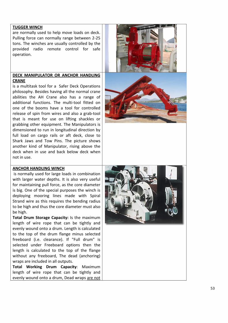
53
TUGGER WINCH are normally used to help move loads on deck. Pulling force can normally range between 2‐25 tons. The winches are usually controlled by the provided radio remote control for safe operation.
DECK MANIPULATOR OR ANCHOR HANDLING CRANE is a multitask tool for a Safer Deck Operations philosophy. Besides having all the normal crane abilities the AH Crane also has a range of additional functions. The multi‐tool fitted on one of the booms have a tool for controlled release of spin from wires and also a grab‐tool that is meant for use on lifting shackles or grabbing other equipment. The Manipulators is dimensioned to run in longitudinal direction by full load on cargo rails or aft deck, close to Shark Jaws and Tow Pins. The picture shows another kind of Manipulator, rising above the deck when in use and back below deck when not in use. ANCHOR HANDLING WINCH is normally used for large loads in combination with larger water depths. It is also very useful for maintaining pull force, as the core diameter is big. One of the special purposes the winch is deploying mooring lines made with Spiral Strand wire as this requires the bending radius to be high and thus the core diameter must also be high. Total Drum Storage Capacity: Is the maximum length of wire rope that can be tightly and evenly wound onto a drum. Length is calculated to the top of the drum flange minus selected freeboard (i.e. clearance). If "Full drum" is selected under Freeboard options then the length is calculated to the top of the flange without any freeboard, The dead (anchoring) wraps are included in all outputs. Total Working Drum Capacity: Maximum length of wire rope that can be tightly and evenly wound onto a drum, Dead wraps are not

54
included in these outputs since these wraps must remain on the drum at all times. Recommended Working Capacity: An approximate number equal to 80% of Total Working Drum Capacity. This is a real world estimate of what can be expected due to less than perfect winding practices. Dead wraps are not included in these outputs since these wraps must remain on the drum at all times. Dead Wraps: The first few wraps of the wire rope around the drum (commonly known as the "dead m wraps") provide a simple and secure method of anchoring the wire rope to the drum. This (anchoring) is accomplished by the friction (of the dead wraps) tightening against the drum barrel, as a load is applied. As the load on the wire rope increases so does the anchoring effect. It is critical that the recommended number of dead wraps remain on the drum at all times in order for the load to be held. The number of dead wraps varies according to what prevailing agency or regulatory body’s rules are followed. In the United States, Ingersoll Rand exceeds ANSI / ASME B30.7 (BASE MODUNTED DRUM HOISTS) by recommending that a minimum of (3) dead wraps are kept on the drum at all times. (Note: Because of the dead wraps the aMODUnt of usable wire rope on the 1st layer is diminished slightly. This has been factored into each of the drum calculator outputs. Freeboard: Freeboard is the aMODUnt of space from the top layer of the wire rope to the outside of the drum flange. A given aMODUnt of freeboard is maintained to prevent the wire rope from inadvertently coming off the drum during use. The aMODUnt of freeboard is dependent upon the prevailing agency or regulatory body. United States, follows ANSI / ASME B30.7 (BASE MODUNTED DRUM HOISTS) which recommends a minimum of ½" of freeboard be maintained. For your convenience the freeboard selection box allows you to choose various options or input your own requirements. Note: The one exception to this is Full Drum

55
Storage. When the winch is not being used to move a load, the wire rope may be spooled to the top of the flange. This practice is for storage purposes only and not recommended when the winch is being used under a load. Fleet Angle: Fleet Angle is the angle between two lines; the 1st line drawn from the center of the fixed sheave to the drum (perpendicular to the drum axis). The second lines are drawn from the center of the fixed sheave to the drum flanges. In order to promote proper spooling of the wire rope it is recommended that a fleet angle of 1 / 2 to 1‐ 1 / 2 for a smooth drum, and 1 / 2 to 2 for a grooved drum, be maintained. Exceeding these recommendations may cause poor spooling from rope piling up, and possible damage to the wire rope through crushing and abrasion.
STORAGE WINCHES have a very high capacity for storing cable, wire or synthetic rope. As the main purposes is storing and transfer of cable, wire and rope the constant pulling capacity is normally between 1 ‐ 5 tons. A considerable factor of selecting an AHTV in pre laid operations is the capacity to store wire or polyester mooring lines. This makes the difference in how many lines you can transport in one shot therefore saving time in the overhaul operation.
CHAIN GYPSY (English) or WILDCATS (American) The wheels on either a vertical or horizontal windlass provide for either chain or line to be engaged. The wheel for line is termed a warping head, while the chain handling wheel is variously referred to as the gypsy (in the UK) or wildcat (in North America). For clarity in communication the generic term chain‐wheel is often used. It is important that the chain wheel match the chain size (i.e. the link pitch) closely. Even a small difference in link size or consistency can cause undue wear on the chain‐wheel and/or cause the chain to jump off the windlass when the winch is operating,

56
particularly during payout, a runaway condition sometimes referred to as "water spouting" should it occur at high speed. On the AHTV they are usually interchangeable therefore they can match the Rig’s Chain considered. They are located on both sides of the anchor handling winch leading the away of the chain from and to the chain lockers. SMIT BRACKETS fitting welded on deck to enable towing connections to be made quickly and securely; the bracket consists of a large sliding pin to receive the eye of a tow line. Normally located on the bow of an AHTV is very useful to connect a second AHTV to the bow of the first AHTV in case of lack of Bollard Pull. It was named after the inventor, Dutch towing specialist company, Smit International.
TUNNEL THRUSTERS Normally fitted with vertical shafts and variable pitch propellers, they are extensively utilized for the bow and aft transverse thrust on AHTV.
AZIMUTH THRUSTERSAn azimuth thruster is a configuration of ship propellers placed in pods that can be rotated in any horizontal direction, making a rudder unnecessary. These give ships better maneuverability than a fixed propeller and rudder system. Motor inside the ship is connected to the pod by gearing. The motor may be diesel or diesel‐electric.

57
RETACTABLE AZIMUTH THRUSTERS By rotating the underwater part through 360°, the full propulsive power can also be used for manoeuvring and for dynamic positioning (DP) of the ship. Sometimes thrusters below the hull are needed, which can interfere with operations in harbors’ or other applications. For this area of application, has developed hydraulically retractable propellers. These are retracted into the hull for open‐water service and lowered for manoeuvring and dynamic positioning at the place of operation.
2) ANCHOR HANDLING CERTIFICATES Copies of the following valid documents shall be available:
1. Certificate of registry 2. International load line certificate 3. Certificates of class for hull and machinery 4. Cargo ship safety equipment certificate 5. Cargo ship safety radio certificate 6. Safety Construction Certificate 7. Certificate of safe manning 8. International Oil Pollution Prevention Certificate 9. Safety Management Certificate 10. International Ship Security Certificate 11. Ballast Water Exchange Certificate (if required) 12. Certificates for all required bridles, chains, tow wires, pennants, stretchers, shackles and connecting
links. 13. Bollard Pull Certificate (by a recognized authority or body) 14. Approved Stability Booklet. 15. Dangerous good certificate if necessary for the operations 16. SALVAGE EQUIPMENT
For Ocean‐Going Salvage Tugs (ST) details of the salvage equipment should be also submitted.
3) CRITERIA FOR SELECTING THE RIGHT AHTV FOR THE JOB
Considering for simplicity water depths in the range of 1000 Mt WD where the centenary moorings composed by 16 Tons anchor and an all 3.1/4”chain line are deployed with the chain chaser system. Forces seen by the AHTV are produced by the weight of the system and the requirement to “stretch” the line to get the anchor out to its target distance. The following list is meant to provide guidance when choosing vessels for this application (deep water mooring) and is not intended to preclude Installation‐specific requirements:

58
a) Minimum Bollard pull certified at +/‐ 180 Tons. In evaluating the bollard pull necessary for a given operation, shall be taken in due account the reduction in bollard pull when considering heavy weather conditions. A vessel indented to stretch a mooring line in adverse (transverse) weather direction, the continuous utilization of the shaft generators to activate bow, stern, azimuth thrusters, winch and deck machinery will draw up to the 30% of the total Bollard Pull capacity. Thus a Vessel rated 180 TBP, may end to have in adverse conditions only 120 TBP available for the real Pull, the remaining 60 tons are employed to keep the course. Vessel documents shall indicate depletions in BP Capacity with both the Shaft Generators on full power mode. (See also Chapter 13 how this has affected the Bourbon Dolphin incident)
b) Stern and bow thrusters of sufficient aggregate horsepower to maintain station while running anchors in 25 knot beam wind and associated sea conditions.
c) Anchor / towing winches with the certified ratings as dynamic in‐haul and braking capacity on first layer of 400 Tons and a static holding capacity of 500 Tons
d) Total combined winch capacity for 1800 Mt x 83mm Minimum active work wire without spooling from a storage winch, not considering the Dead Wrap or Dead Man Wire that usually covers the first Line on the winch (about 100 Mt). Storage wheel to be fitted with a Spare Work Wire brand new of the same size of that in use. Work wire shall not be confused with Tow Wire. Tow Wire shall not be utilized as Work Wire because will compromise the capacity of vessel as Towing Vessel.
e) Winch drum diameter (D) approximately sized to wire a diameter ratio (D/d) of 18 to 21/1. Minimum work wire diameter is 83 mm .
f) Level wind devices meter. g) Chain handling wildcat with whelps sized for Installation chain (3.1/4 inches in this case). h) Chain locker(s) and/or aft deck space capable of stowing at least one line of Installation chain. i) Stern roller rated to 600 Tons min. (Split roller if in pre‐laid) j) Triplex Jaws, Karm Forks or similar hydraulic stopper, two (2), hydraulic, rated to 600 tons and sized for
Rig’s Line chain k) Hydraulic pop‐up 'guide' deck pins and capstans. (Two sets if in pre‐laid case) l) Hydraulic deck tugger winches (2) rated to 15 Tons +. m) Work wires should be fitted with "Pee Wee" or "Goldnose" type closed spelter sockets. Length and
diameter should be as noted above for each water depth category with a ratio 1.6 Minimum for the maximum given water depth of the location.
n) A continuous, single length work wire is preferred. In case who section of work wire to be terminated with connected with "Pee Wee" or "Goldnose" type closed spelter sockets and connected with detachable chain connecting links of the Kenter or Ramfor type. In no way normal shackles shall be rolled on a winch drums as it will damage the wire above and below the shackle itself.
o) Minimum of two (2) cross over chains, 3 in. diameter, eight (8) links long and two (2) x 3. ½ “. eye to eye "on load" type swivels that rotate under load. These are used for chain / wire cross over connections.
p) Steel plate lined aft deck (anchor handling area) q) One full set of spare work wire and connectors as above. r) One (1) ultra wide radius 'J' hook, suitable for chasing and recovering mooring chain or wire. s) One (1) Grapnel 200 tons rated t) One (1) mini container ready on deck with tools, chisels, cutting torch etc.

59
CHAPTER 5 SEMISUBS MOORING EQUIPMENT 1) SEMISUBS’S MOORING LINES The marine equipment necessary for the mooring operations are normally enumerated in the technical specs of the rig of reference. An assessment of the quality, quantity and state of usage shall be part of the professional Rig’s acceptance inspection. If we consider a Rig with a Class A anchor already set with an angle these equipment basically are:
a) Mooring Chains • Mooring chains to be manufactured according to one of the following specifications:
API Spec 2F, Specifications for Mooring Chain RCS (Recognized Classification Society) –Rules for Offshore mooring Chains
b) Mooring Wires • Mooring wire ropes should have no fiber core. Blocking compound of good quality should be used to
block the spaces between the wires. The end of each rope section should be terminated with resin or zinc poured sockets. Mooring wire rope and sockets should meet material, design, manufacture and testing as specified in the Classification Rules.
• Non torque balanced wire ropes, such 6 and 8 strand ropes, the torque and twisting characteristics should be considered in the mooring line characteristics and in the mooring line handling procedures to ensure proper mooring application and the safety of the handling crew involved in the operation. Wire rope manufacturers should provide users twist/torque data for the allowable tension range as part of the wire ropes characteristics.
• Contact of a wire rope in the dip or trash zone may cause excessive wear in the rope jacket or excessive free bending at the sockets. This condition should be avoided, especially for permanent or long moorings.
c) Connecting Links • Connecting links as shackles and detachable should be made by forged or cast material. They should be
fully inspected by non‐destructive testing (magnetic particle, die penetrant, etc) according recognized standards. Cast connecting links should be also be examined by xray or ultrasonic tests to detect internal casting defects.
d) All Wire Rope Mooring System • Because the wire rope is much lighter than chain, wire rope provides a greater restoring force a given
pretension. This becomes increasingly important as water depth increases. However to prevent anchor uplift with an all wire system, a much longer line is required. A disadvantage of an all wire rope mooring is wear due to long term abrasion where it contacts the sea bed. For these reasons, all wire rope systems are seldom used for mobile or permanent moorings.

60
e) All Chain System • Chain has shown durability in the offshore operations. It has better resistance to the bottom abrasions
and contributes significantly to the anchor holding capacity. However deep sea moorings imposes a increasingly weight penalty to the vessels loads carrying capacity and high initial tension requirements.
f) Combination Mooring System • In this system a mooring line can be a combination of chain, wire and sometimes fiber ropes. It has a
better resistance to abrasions where the line touches the bottom and contributes to anchor holding capacity. Normally the chain is connected to the anchor and the length is between 2000 and 3000 ft. Other advantages that makes attractive this solution is the reduced pre‐tensioning and the higher restoring forces.
When a rig operates with a combination Chain/Wire it worth to remind a particular moment during the deployment and retrieval of the mooring line, which in some way can be considered a disadvantage: the moment of transition between the chain and the wires or the changeover. Both chain and wires are stored in the bottom of the columns for stability. Chain is stored in the chain locker while the wire is stored on the winch drum. The chain is paid out and retrieved by the windlass located usually in couples on the top of each column on the Rig’s deck, while the wire rope is paid out and retrieved by the winch . There is a moment when the total shot of chain ends and shall be executed the connection with the wire line. There are different methods to safely organize this operation and this depends on the arrangement of the selected Rig. In any case this operation results in the stoppage of the pay out or retrieval of the mooring line and the AHTV remains dead in the water with all the weight of the chain hanging down from the stern roller and this is a very sensitive moment for the AHTV in managing the weather to remain in position. 2) MOORING EQUIPMENT
WINDLASS The most common method of handling and tensioning chains is through the use of a windlass. The windlass consists of a slotted “wildcat” which is driven by a power source through a gear reduction system. As the wildcat rotates, the chain meshes with the wildcat and lowered into the chain locker. Once the chain is hauled‐in and tensioned, a chain stopper or brake is engaged to hold the chain. Windlass has proven to be a fast and reliable method for handling and tensioning chains. See side figure of a double windlass on the Rig’s deck.
FAIRLEADS AND STOPPERS Mooring lines are subjected to high wear and stress at the fairlead and stopper arrangements. The long term service of a mooring system requires that fairlead and stopper arrangements be carefully designed to minimize wear and fatigue. Mooring chains and wire ropes are often stopped off at the vessel in order to take direct mooring loads off the
Chain Stopper Fairlead

61
winch. Fairleads should provide sufficient sheave to rope diameter ratio to minimize tension bending fatigue. Wildcats normally have a ratio of 7 to 9 pockets. Sheave for for wire rope have a diameter 16 to 25 times the wire rope.
DRUM TYPE WINCH Conventional drum type winch is the most common method for handling wire ropes. Drum type winch consists of a large drum on which the wire rope is wrapped. The base of the drum is often fitted with special grooves sized specifically to the size of the wire rope being handled. The groves controls the positioning of the bottom layer but for subsequent layers of wire ropes, an external guidance mechanism as a level‐wind is often used to control the positioning of the wire rope on the drum. The tensioning capacity of the winch is a function of a number of wraps on the drum: more layers, less tensioning. Normally rigs keep always an amount of wires remaining on the drum as safety factor in case to move away from the well or in case of re‐spudding nearby. The winch on the deck of the rig in the picture denotes all wire mooring system. In a chain/wire mooring winch is locates in the pontoon.
THE J CHASER The J‐chaser (fig. ) is used on mooring lines where the anchor has to be recovered and no permanent chaser has been installed, or the normal recovery mechanism has failed. In other cases the J‐chaser is used simply to keep a chain free from a pipeline during deployment of the anchors. The chaser is deployed over the stern roller of an AHV at approximately 1/3 of the water depth. The chaser is towed across the mooring catenary until it catches the chain. It is then towed into contact with the anchor shank/fluke for anchor break‐out and retrieval.
PERMANENT CHAIN CHASER As a practical alternative to the buoy and pendant, the permanent chain chaser (fig.) was introduced. Originally, simple shackles were used; these were followed by special cast oval rings which were attached to a pendant by a ‘bight’ of chain and shackle. Very soon afterwards the pear‐shaped chaser with shackle eye was introduced. The design of these chasers offers superior sliding and penetration properties.

62
DETACHABLE CHAIN CHASER For rigs in service it is sometimes preferred to equip the mooring with a chaser which does not require the anchor chain to be broken and re‐made. Detachable chain chasers (fig.) were introduced to satisfy this need. The withdrawal and replacement of the single bolt permits easy assembly of the chaser on the mooring cable.
PERMANENT WIRE CHASER The permanent wire chaser (fig.) was introduced when rigs moved to deeper waters, and composite wire/chain mooring systems became necessary. The chaser incorporates a ‘rocker’ which is centrally counted on a hinge bolt. The rocker has two opposing grooves, and when the chaser is engaged with the mooring line, the wire slides through one of these grooves irrespective of the angle which the chaser makes with the mooring. The large radius at the base of the groove assists in reducing wear of the rocker and avoids severe ‘opening’ of the lay of the wire if a loop of wire is pulled during the handling process. The material of the rocker is not as hard as the material of the wire. This means that wear is taken by the rocker without damage to the wire and, because the rocker is easily removable, replacement is relatively inexpensive. The permanent wire chaser is easily detachable by removal and re‐assembly of the hinge bolt and rocker. Some designs of wire chaser incorporate fully rotating rollers over which the mooring wire passes. To be effective such rollers need to be of a large diameter and require to be supported by bearings. They are consequently larger, heavier and much more costly.
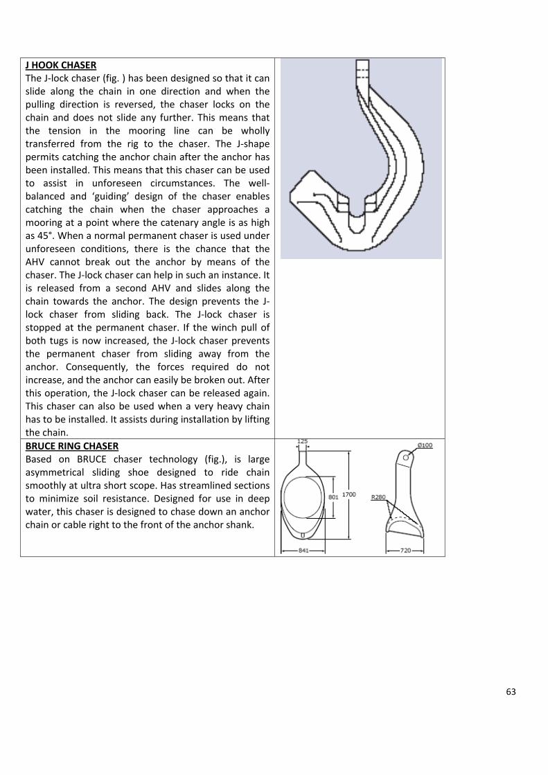
63
J HOOK CHASER The J‐lock chaser (fig. ) has been designed so that it can slide along the chain in one direction and when the pulling direction is reversed, the chaser locks on the chain and does not slide any further. This means that the tension in the mooring line can be wholly transferred from the rig to the chaser. The J‐shape permits catching the anchor chain after the anchor has been installed. This means that this chaser can be used to assist in unforeseen circumstances. The well‐balanced and ‘guiding’ design of the chaser enables catching the chain when the chaser approaches a mooring at a point where the catenary angle is as high as 45°. When a normal permanent chaser is used under unforeseen conditions, there is the chance that the AHV cannot break out the anchor by means of the chaser. The J‐lock chaser can help in such an instance. It is released from a second AHV and slides along the chain towards the anchor. The design prevents the J‐lock chaser from sliding back. The J‐lock chaser is stopped at the permanent chaser. If the winch pull of both tugs is now increased, the J‐lock chaser prevents the permanent chaser from sliding away from the anchor. Consequently, the forces required do not increase, and the anchor can easily be broken out. After this operation, the J‐lock chaser can be released again. This chaser can also be used when a very heavy chain has to be installed. It assists during installation by lifting the chain.
BRUCE RING CHASER Based on BRUCE chaser technology (fig.), is large asymmetrical sliding shoe designed to ride chain smoothly at ultra short scope. Has streamlined sections to minimize soil resistance. Designed for use in deep water, this chaser is designed to chase down an anchor chain or cable right to the front of the anchor shank.

64
GRAPNELS The grapnel was designed as a “fishing” tool primarily for the purpose of recovering an anchor and chain which has become detached and has fallen to the sea bed. The operational sequence is as follows:

65
CHAPTER 6 WIRE ROPES
1) WIRE ROPES CATEGORIES
Wire ropes can be grouped into two broad categories by the type of central core used. Independent Wire Rope Core (IWRC) ropes are the stronger of the two and offer the greater resistance to crushing and high temperatures. Fibre core (FC) wire ropes while weaker, offer advantages in terms of flexibility, weight and of course price. Along with the diameter, two numbers are normally used to define the construction of a wire rope. The first refers to the number of strands in the rope and the second to the number of wires per strand. In general, the greater are the number of wires, the greater the flexibility of the rope. As the number of strands increase, so the section of the rope tends towards an even circle which is essential for the wear characteristics of ropes which pass over sheaves. While it is impossible to include a comprehensive list of all wire ropes in a publication of this size, this section should be a useful reference guide for those constructions in common use.
a) Selection of wire ropes
Wire ropes are affected by wear and bending as they operate over sheaves and drums. When selecting a wire rope for a particular service in addition to the minimum breaking load, the required resistance to abrasion and to bending fatigue must be considered. Resistance to bending fatigue and resistance to abrasion require two different types of rope. Maximum resistance to bending fatigue is obtained from a flexible rope with small outer wires whereas to obtain maximum resistance to abrasion a less flexible rope with larger outer wires is required. The correct selection of a wire rope involves a compromise between these two characteristics, the following diagram gives an indication of the relative abilities of various constructions to withstand wear and abrasion. Where a rope may be subjected to crushing and/or distortion a steel wire core is recommended.
b) Corrosion Where corrosive conditions exist the use of galvanized wires is recommended. In addition to physical protection due to the complete envelopment of steel wire, zinc provides sacrificial protection as corrosion of the steel is prevented until the zinc is removed from comparatively large areas. In extreme cases corrosion can be combated by the use of stainless steel wire rope. Further guidance to rope selection is given in BS6570 Code of Practice for .The selection, care, and maintenance of steel wire ropes..
c) Lubrication Unless otherwise indicated, by the customer or the intended duty, our ropes are thoroughly lubricated both internally and externally, during manufacture. In addition to providing internal lubrication for free movement of the component wires, the lubricant also gives protection against corrosion. Due to the internal pressures set up as the rope flexes, and other outside

66
influences met during its work, the original lubricant may soon be reduced and to ensure maximum rope life supplementary lubricant should be applied periodically during service. How rigorous the duty or corrosive the conditions will dictate the frequency of these applications. All steel wire ropes, including galvanized and stainless, will derive benefits from lubrication.
d) Main core of ropes The function of the core in a steel wire rope is to serve as a foundation for the strands, providing support and keeping them in their proper position throughout the life of the rope. Fibre cores are generally used, as, when impregnated with grease, they help to provide internal lubrication as well as contributing to flexibility. Where high resistance to crushing or to heat is needed and where additional strength or low stretch is required steel wire cores are used. Fibre Main Core Wire Strand Main Core (WSMC) Independent Wire Rope Main Core (IWRC) 2) ROPE LAYS
a) Length of a lay
That distance in a rope, measured parallel to its axis, in which a strand in a rope makes one complete turn about the axis of the rope. Variations in length of lay alter the elastic properties of the rope, e.g. shortening the length of lay will increase a rope.s elastic stretch but slightly reduce its breaking load.
b) Ordinary (regular) lay and Lang.s Lay In an ordinary lay rope the direction of lay of the outer layer or wires in the strands is opposite to the direction of lay of the strands in the rope, whereas in a Lang.s lay rope the direction of lay of the outer layer of wires in the strands is the same as the direction of lay of the strands in the rope. Both ordinary lay and Lang.s lay ropes are normally laid up in a right hand direction, but left hand lay can be supplied on request. Ordinary lay ropes are suitable for all general engineering purposes. A Lang.s lay rope offers a greater wearing surface and can be expected to last longer than an ordinary lay rope on an installation where resistance to wear is important, but it has less resistance to unlaying than an ordinary lay and its application must be limited to installations in which both ends of the rope are secured against rotation.
c) Equal lay An equal lay construction is one in which the wires in the strand are so spun that they will have an equal length of lay. It follows that the contact between all wires in the strand is linear. Ropes of this construction are not subject to failure by the bending of wires over the wires of the underlying layer. Example 6 x 19 (9/9/1) 6 x 19 (12/6 + 6F/1) 6 x 36 (14/7 & 7/7/1)
Seale Filler Warrington
d) Cross lay A cross lay construction is one in which the wires in successive layers of the strand are spun approximately the same angle of lay. It follows that the wires in successive layers make point contact. Where ropes are operating over pulleys, nicking of wires and secondary bending at these points of contact occur, and failure of the wires by early fatigue may result. Example 6 x 19 (12/6/1) 6 x 37 (18/12/6/1)

67
e) Rope and strand description
For most applications wire ropes are constructed with six strands which are generally laid round a fibre or wire rope core. It is seldom that fewer strands are used but, for special applications, more than six are employed. Throughout these following illustrations, the figures given to describe the construction of a rope, are arranged so that the FIRST figure always indicates the number of STRANDS in the rope, and the SECOND figure the number of WIRES in each strand. Eg 6 x 7 denotes a rope constructed with 6 STRANDS each strand comprising 7 WIRES 8 x 19 denotes a rope constructed with 8 STRANDS each strand comprising 19 WIRES
Where there are seven wires in a strand, they can be arranged in only one way, ie 6 around 1, given in the catalogue as 6/1, a rope arranged 6 strands each of 7 wires is shown as 6 x 7 (6/1) Where there are more than seven wires in a strand, they can sometimes be arranged in different ways and it is because of this that in the pictures that follow, arrangement of the wires in the strand is invariably shown in brackets following the total number of wires per strand, eg where in 6 x 19 construction the 19 wires in each strand are laid 12 around 6 around 1 centre wire, the construction is shown as: 6 x 19 (12/6/1) Similarly, where the 19 wires in a strand are laid 9 around 9 around 1 centre wire, or “SEALE” the arrangement is shown as: eg 6 x 19 (9/9/1) “SEALE” Where the wires in the strands are laid on the “WARRINGTON” principle, the figures denoting a layer of large and small diameter wires are separated by the word “and”; eg 6 x 19 (6 and 6/6/1) “WARRINGTON” Where small .FILLER. wires are introduced between layers of wires they are denoted by the “+” sign and the number of “FILLER” wires followed by the letter “F” eg 6 x 19 (12/6+6F/1) “FILLER”
f) Preforming Preforming is a manufacturing process which has the effect of relieving the wires and the strands of much of the internal stress which exist in non preformed ropes. During the process the strands and wires are given the helical shape they will assume in the finished rope. In a preformed rope broken wires do not protrude and greater care is required when inspecting for broken wires. Preformed rope offers certain advantages over non‐preformed rope, eg:

68
1. It does not tend to unravel and is less liable to form itself into loops or kinks and is thus more easily installed
2. It is slightly more flexible and conforms to the curvature of sheaves and pulleys 3. Due to the reduction in internal stresses it has greater resistance to bending fatigue
Unless otherwise requested all ropes are supplied preformed.
NON‐PREFORMED ROPE
In PREFORMED rope the wires and strands are given the helix they take up in the completed rope
PREFORMED rope may be cut without servings although care must always be taken
3) COMMON STEEL WIRE ROPE CROSS SECTIONS ROUND STRAND
4) CORRECT SPOOLING OF ROPE ON DRUM The sketch shown below may be used to determine the proper direction of rope lay for spooling or winding on flat or smooth face drums. When a rope is wound on to a drum any tendency of the rope to twist when tension

69
is released will be in a direction which would untwist the rope at the free end. The advantage of spooling in the correct directions is that when any load is slackened off the laps on the drum will hug together and maintain an even layer. With incorrect spooling the laps will move apart on removal of load and when the load is reapplied the rope may criss‐cross and overlap, and flattening and crushing of the rope will result. The correct spooling direction for right and left hand lay ropes is shown in the sketch below. This applies to both ordinary and Lang.s lay ropes.
UNREELING UNCOILING
Pass a shaft through the centre of the reel and jack it up to allow the reel to revolve freely. Pull the rope straight ahead keeping it taut to prevent it from loosening up on the reel.
Heavy coils should be placed on a turntable and two crosspieces placed on top of the coil to prevent laps springing out of place and kinking. Light Flexible Ropes may be rolled along the ground so that the rope lies straight.

70
5) WIRE ROPE DAMAGES The life of a rope depends on many factors and includes:
a The integrity of rope records and certification b Wear and tear of rope contact points c Operator skills
The technical characteristics of a wire rope can be easily determined of the beginning of its life cycle whilst monitoring high contact areas can also be effectively managed. Operator skills, however, are more difficult to monitor. Typical reasons for a wire rope to be withdrawn from service are listed below:
a Unsuitable rope composition, diameter and quality for purpose b Ropes wound over or across each other c Lack of regular and correct lubrication d Use of incorrect reels and drums e Use of misaligned reels and drums f Use of reels and drums with unsuitable grooves and/or flanges g Damage caused by ropes protruding from reels and/or drums h Ropes being affected by humidity, chemicals or heat i Use of unsuitable rope joints j Looped ropes k Excessive loads l Damaged rope particles penetrating the internal structure The following conditions should be noted when examining a rope: a Decrease in diameter b General wear and tear c Lay length changes d Traces of shock and stretch e Corrosion f Broken wires and their position in the rope structure
6) CORRECT/INCORRECT LAYERING When working with long lengths of wire it is essential that the wires are spooled onto the winches correctly. Wires should be installed using spooling machines that can apply back tension to the winch. It is also important to check whether the winch is over or under wound, for left or for right stranded wire rope. The application of tension and the employment of correct spooling techniques will ensure that the wraps of wire will nestle neatly and tightly when spooled onto a winch. If wire is spooled slackly, or incorrectly placed on the winch, it will result

71
in damaged wire. If an outer layer is pulled through the inner wraps towards the core of the drum it can result in the wire being cut.
7) METHOD OF APPLYING BULLDOG GRIPS
The bulldog grip should be fitted to wire rope as shown in Fig 1, and not as shown in Fig 2. The bridge of the grip should invariably be fitted on the working part of the rope, and the U‐bolt on the rope tail or dead end of the rope. Grips should not alternate in position on the rope. As a safety measure and to secure best results it is important to re‐tighten all grips after a short period in operation, for, due to the compression of the rope under load, there will be a tendency for the grips to loosen. Refer to the manufacturer’s instructions for quantity of grips recommended.

72
CHAPTER 7 CHAINS AND ACCESSORIES
1) ANCHOR CHAINS AND ACCESSORIES
Chains consist of chain links which can be either stud‐links or stud‐less links. The chain accessories include shackles (anchor shackle, joining shackle, Kenter joining shackle, swivel shackle, Ramfor connector, pear shackle, mooring shackle, swivel‐forerunner, etc.)
An anchor cable is an assembly of a number of individual units properly secured together. These units are connected to the anchor by means of a swivel piece made up of shackles, swivels, and special link. Each shot or shackle (=25 m) of chain is joined together with a detachable link.
Studlink anchor‐chain is used for permanent and emergency anchoring of ships and other floating installation. The studs secure that every link comes into the gypsy (cable lifter), in correct position.

73
Studless anchor chain
Studless anchor chain are made to be used in permanent moorings when the chain will not go over a gypsy. The advantages are: less weight, fit bigger shackles without end‐links and avoid problems with loose studs. Studless anchor‐chains are available in the same steel qualities as studlink anchor‐chains. Studless anchor‐chains in every size are supplied both for fish‐farm mooring and offshore installations.
Anchor Shackles ‐ Type D are used to connect the anchor to the anchor‐chain. The shackle requires a studless endlink at the chain‐side, and fits the anchors crown‐shackle. Anchor‐shackles Type D ready in stock in most sizes from dia 12,5 mm up to dia 137 mm..
Kenter Joining Shackles A kenter joining‐shackle is made to join two lengths of chain and to fit in the gypsy (chain‐wheel). Kenter Joining‐shackles are in most sizes.

74
The swivel‐shackle The swivel‐shackle (often called super‐swivel) was made to minimize the space between the anchor and the chain. It can connect both to a crown‐shackle and also direct in the anchor‐shank. The other end fit a studless endlink or a common link with stud. These shackles are a more expensive solution then the traditional swivel‐forerunner, but often used to avoid the swivel in the chain‐stopper.
Anchor D‐shackles are used to connect the anchor to the anchor‐chain. The shackle require a studless endlink at the chain‐side, and fit the anchors crown‐shackle.connect the anchor to the anchor‐chain. The shackle require a studless endlink at the chain‐side, and fit the anchors crown‐shackle. Anchor‐shackles Type D ready in stock in most sizes from dia 12,5 mm up to dia 137 mm.
Pear Shackles ‐ Type Baldt
Pear shaped End shackle can be used to connect the anchor‐chain to the anchor. In the USA it often replace the D‐type anchor‐shackled used in the rest of the world. It can also connect a smaller chain to a bigger chain. Pear shaped End shackle in every size from No 2 to No 9 to cover anchor‐chain dia 19 – 95mm always ready in stock.

75
Connectors type RAMFOR
Connectors type RAMFOR has the same outside shape as a traditional Kenter joining shackle, but with improved fatigue properties. The difference is the design of the interior. The RAMFOR and RAMFOR Slim designs have a locking head of a different design than that of the Kenter joining shackles. This locking head has been designed to provide a larger load‐carrying area, which in turn gives a better stress distribution. RAMFOR and RAMFOR Slim type connectors have the same outside shape as the Kenter joining shackle and the RAMFOR Slim has a reduced thickness equal to the Baldt type connector. The slim shape will enable the RAMFOR Slim connector to be used on every mooring system on semi‐submersibles, offshore loading systems etc. and will fit any wildcat (cable lifter, gipsy).
A Swivel‐forerunner is the most common swivel‐connection used on ships. It is economical and safe. The end with a studless endlink fit the anchor‐shackle, and the end with a common link for the kenter‐shackle. Swivel‐forerunner ready in stock in most sizes from dia 12,5 mm up to dia 137 mm.

Baldt
Swive
Safet
Standsurfac
t joining sha
el‐shackle t
y Bow Shac
dard shacklece. They are
ackles for st
type A
ckles
es type G‐2e certified w
tudlink anch
130 are usewith a safet
hor chain.
ed worldwidy factor of 6
de for both 6. Working
mooring anload limit x
nd lifting. Thx 6 = Breaklo
hey have hooad
ot clip galva
76
nized

77
The mooring shackles are similar to the G‐2130 shackles, but are made with a bigger gap to easier fit the anchors and other mooring accessories.
The mooring shackles are similar to the G‐2130 shackles, but are made with a bigger gap to easier fit the anchors and other mooring accessories.

78
CHAPTER 8
RIG MOVE ‐ Semisubmersible
1) AGREED PROCEDURES AND RESPONSABILITIES
Rig Moving operations and towing are potentially hazardous. Installation personnel should appreciate vessels’ operational limitations, including power and freeboard. Safety of vessel and crew is paramount. The guidance in this section applies equally to all types of MODUs. To avoid any conflict of interest the Tow Masters and Operators Marine Representatives should be sourced from Independent Contractors.
a) Responsibilities of the Operating Company The Operating Company is responsible for obtaining the information needed to anchor a MODU in a field. The operating company shall:
a) produce an overview of infrastructure on the seabed, sea bottom conditions and any obstructions. Provide charts with positions both hard copies and electronic versions’
b) specify minimum horizontal and vertical distances to infrastructure and pipelines on the seabed for anchors and anchor lines.
c) ensure adequate planning (including contingencies) and risk assessment of the entire anchor handling and towing operation.
d) provide weather, wave and tidal stream data (Chapter 2). e) organize rig move meeting well in advance (two weeks) of the start‐up and written procedures
for Rig move should be agreed upon with all relevant parties. These should identify key roles and responsibilities
f) obtain or determine who is to obtain vessels and mobilize according to plans. g) make sure to release the rig move plan (including maximum calculated loads) to be issued to
enable nominated ship owners to confirm that a suitable vessel has been selected h) provide to vessel owner and vessels, details of maximum calculated loads for the operation. i) organize inspection of selected vessels to verify suitability j) when feasible, make all the vessels available for a common briefing in port prior to mobilization.
This briefing should be attended by Master\Mates and deck crew of vessels along with rig representatives.
k) obtain positioning equipment and positioning personnel l) determine logistics needs (deck cargo, bulk) m) inform vessel and MODU about the status of the operation at all times n) Supervise and agree any proposed crew changes during period to be conducted to allow
sufficient time for a briefing on work scope and experience transfer to be completed.
b) Responsibilities of the MODU Owner The owner of the MODU shall:
a) prepare a work specification or "Rig Move Plan” that covers the entire anchor handling or towing operation. The work specification shall be in English unless otherwise agreed. Depending on local requirements rig move procedures may be prepared by the Operator.
b) supervise the operation in the field c) communicate any changes of the work specification to all the parties involved

79
d) ensure that the RMP has been reviewed and is understood by vessels and key personnel that participate in the operation, and verify that Risk Analysis and Safe Job Analysis have been performed.
e) ensure that satisfactory anchoring/mooring analysis have been prepared in compliance with national /industry requirements where relevant.
f) notify Authorities of MODU departure and arrival in accordance with local requirements. g) ensure all anchor handling equipment used and permanent equipment is certified h) obtain necessary anchoring equipment in accordance with the anchor handling work
specification, i) ensure MODU is adequately manned by competent personnel taking into account hours of
rest requirements and the scope of work. Obtain extra personnel as required to cover 24/7 operation.
j) identify potential backload prior to MODU move.
c) Responsibilities of the OIM : The OIM has overall responsibility for the safety of the installation and personnel at all times as per statutory requirements and MODU owners' policy. However he may delegate some of the rig move operational tasks to a suitably qualified person such as the Towmaster who should also consult with vessel Masters in the process. The OIM shall:
a) provide information of the last updated Rig move plan b) decides when it is safe and practicable to commence operations within the limitations of the
MODU operating manual, having consulted with the Operators representative. c) be responsible for ensuring that a meeting is held with all relevant personnel (including AHTS
Masters) on board prior to rig move and minuted accordingly, with an appropriate entry in the log book to that effect.
d) have procedures in place to monitor vessels operation, provide status of the operation and gather reports
e) ensure fully functional communication between all involved parties f) be sole point of contact through which all rig move notifications and exterior communications
will pass. Ensures that all relevant authorities are kept informed of the rig move status, as required.
g) liaises and communicates with the Operating Company representative on all matters concerned with the rig move operation and any deviation from the proposed rig move procedures.
d) Responsibilities of the Ship Owner
Shipowners are responsible for ensuring vessels and equipment used in all operations shall: a) be in operational order and complies with relevant legislation. b) confirm that the vessel is suitable for the scope of work supplied c) be adequately manned by competent personnel taking into account hours of rest
requirements and scope of work including possibility of 24/7 working. d) negotiate and get approval from Company for proposed crew changes during topics operation
periods. Any crew changes must be conducted to allow sufficient time for a briefing on work scope and experience transfer to be completed.
e) ensure that the vessel is able to calculate and monitor stability information for all stages of the received rig move plan. It is imperative that all Ship Owners provide each AHTS with a ship specific anchor handling manual.
80
f) should complete the MSF Template of data to verify the details above when requested by charterer.
e) Responsibilities of the A/H vessel Master
The Master of the AHTS shall: a) ensure that the manning on board is sufficient based on working hour provisions, anchoring
description and that the crew is rested. Ensure that all AH equipment is in good condition and certificated and meets the work specification
b) report any defects or non conformities to the anchor/mooring equipment found during the operation.
c) ensure that a Risk Analysis has been performed in accordance with the specific work scope, d) ensure that RMP is communicated to all crew members involved in operation. e) ensure that stability of the ship must be calculated for each step in the work scope including
expected dynamic loads f) ensure safety of crew and equipment on board the A/H or towing vessel at all times. The
Master shall stop operations that may put vessel or crew at risk. g) have sufficient bunkers for the planned operation h) be aware that as Lead towing vessel Master is responsible for navigation of the towing
operation, compliance with prepared plans, shall issue appropriate navigational warnings at regular intervals and ensure other towing vessels follow the stipulated plans.
2) RIG MOVE PLANNING
a) Rig move meeting
1. The operating Company should arrange a rig move meeting, preferably a minimum of two weeks before the operation starts. The Rig Move Plan should be distributed to participants in sufficient time for review prior to the meeting. The following are the recommended participants of the rig move meeting:
a) OIM/ Towmaster (preferably the ones on board during the operation) and Representative from MODU owner operations department
b) Onshore and/or Offshore drilling supervisor for operating company c) Onshore logistics representative from operating company d) Marine Representative for operating company e) Representative from owner/operator of pipeline/other installation if relevant. f) Additional specialist personnel as required.
b) The rig move meeting agenda (as a minimum):
1. Review of R/A and HAZOP for anchor handling operation and transfer of experience 2. Weather limitations and definition of operational criteria 3. Charts 4. ROV inspection requirements 5. Anchoring/mooring analysis, anchor pattern and work specification (RMP) including
maximum calculated loads and dynamic tensions. 6. Pre‐installation of anchors 7. Vessel requirements; manning, quantity and technical specifications 8. Drawings and sketches of anchoring equipment in the sea 9. Manning on MODU

81
10. Safe job input for vessels and MODU 11. Schedules and drilling operation 12. Contingency plans 13. Equipment lists for AH equipment (including weights and COG) for the individual vessels 14. Sea bottom conditions 15. Communication lines (VHF channels, telephone nos.).
c) Rig move plan
A work specification shall be prepared that provides the necessary background information on the rig move operation and describes the operation at the required level of detail. The purpose of the work specification is as follows:
1. Ensure a safe operation for personnel and the environment 2. Provide common guidelines for standardizing the relocation of the MODU and anchor
handling 3. Anchoring/mooring analysis, anchor pattern and work specification (RMP) including
maximum calculated loads and dynamic tensions. 4. identify and set trigger points which determine operation start /stop or R/A 5. Provide an brief outline of the topics to be covered 6. Must outline framework conditions, use images and diagrams where possible. 7. Is intended for use during the planning, execution, verification and demobilization during
relocation of the AHTS/MODU 8. Shall be in English, unless otherwise agreed.
A management of change process should be agreed with all parties involved. Any deviation from the work specification shall only be permitted in accordance with this agreed management of change.
d) Equipment To maintain vessel’s and MODU’s safe working environment the following should be in place:
1. all equipment operation and maintenance should be according to manufacturer’s instructions;
2. a maintenance system for AH equipment retained on board 3. cutting gear available 4. a safe and effective method of stoppering wire pennants, recognizing likely loads on the wire
and the load‐bearing capacity of wire, termination employed. 5. Alloy ferrule terminations should not be used. 6. monitoring, with regular inspection and maintenance, of roller fairleads on vessels’ deck or
crash barrier to ensure that uplift by e.g. a tugger wire will not dislodge them. 7. suitable lifesaving appliances must be available and immediately accessible
Care must be taken when opening wire coils, in particular pendant wires. Turntables should be used (if available) as coils springing open following release of securing bands may cause injury
e) The Rig Moving Operation 1. Must be according to the rig move plan,
f) Risk Assessment

82
MODU and all vessels involved shall perform SJA before operation starts, in conjunction with the R/A:
1. If an operation has changed from the original plan for which the RA was performed,
personnel must review the new hazards and risks of the changed operation as part of the management of change process.
2. This requires a time‐out and review with personnel involved, performed 3. at the workplace.
g) Reporting
Where required the MODU Owner, in cooperation with vessels and Marine Representative or Towmaster, should report to the appropriate National Authorities as per the national requirements.
h) Anchor securing on deck
When running or recovering anchors over subsea obstructions, anchors must be decked and double secured or disconnected to prevent the anchor dropping uncontrollably off the stern.
i) Bollard Pull
Maximum Bollard pull utilized should not exceed the minimum breaking load of the MODU’s towing arrangement. Use vessel’s tension gauge to monitor. Reference should be made to the vessel’s bollard pull reduction curves.
j) The Towing Operation 1. The passage plan must be carefully developed with regard to water depth, other offshore and subsea
installations, and emergency position. 2. Close attention should be paid to the length and catenary of the tow wire and its relation to the water
depth and weather conditions. 3. Route must keep safe distance from any other installations. Pass on the side that best assures tow will
drift away from the installation in case of black‐out or towline failure. 4. Anti Pirate escort plan to be evaluate in pirate prone areas 5. The passage plan shall not use installations as way points. 6. Obtain regular weather reports. 7. Specify communication lines 8. Assess what support vessels are required. Support vessels’ tasks include, but are not limited to:
i. Monitoring and plotting ship traffic along the towing route. ii. Intercept and warn vessels that approach tow too closely iii. Checking emergency anchoring/jacking location is clear and unobstructed before MODU
arrival. 9. Functioning as back‐up towing vessel, especially in winter months. 10. Identify the MODU’s secondary emergency towing system, establish a readily available retrieval method
for main towing gear, and agree a safe procedure for passing the secondary towing system in all weather conditions.

83
11. Ensure MODU personnel are aware of the time that may be required to rig spare towing wire. If an additional vessel is available as reserve towing vessel on passage, this should be rigged for towing.
k) General Towing Rules Pay close attention to: 1. towline, particularly prevention of any chafing or friction. Either use fiber protection, or regularly adjust
wire length. 2. towing speed and heading: make changes very slowly and in a controlled way. 3. heaving in or paying out towline: when doing so, reduce engine thrust correspondingly to avoid damage
to towline. 4. If towing MODU on anchor chains a good catenary is ensured if MODU pays out an agreed length of
anchor chain. 5. Towing vessels should issue regular navigational warnings. 6. During towing, any other deck work should be risk assessed. 7. In adverse weather the Master to consider if a gog wire may be used to control the towline. 8. Towing in adverse weather, dynamic forces are significant. Exercise great caution, particularly when
waves come in astern.

84
CHAPTER 9 ANCHOR HANDLING
1) ANCHOR HANDLING OPERATIONS (DEEP WATER)
Anchor handling operations in deep water carry significant hazards and these may be location specific.
a) General recommendations 1. Suitability of vessel for location specific operations taking into account environmental and other
variables to minimize damage to work wire from joining shackles use longer continuous lengths of work wire;
2. all wires to be spooled under tension; 3. use work wire swivels to avoid twisting damage from the inherent high loads of deep water A/H ‐ de‐
tension after use. 4. use chain connecting links in the shark jaws. 5. buoys ‐ if any should be launched under controlled tension to avoid shock load damage; 6. method of deploying chain from a locker. Modern vessels can ensure approximately 75% cable‐gypsy
engagement and adequate power availability. On other vessels, lead chain from the gypsy as normal, then pass it down the deck around one or more towing pins to give a lead back up the deck to the opposite gypsy. Then pass chain under and over gypsy to lead back down the deck and over the stern roller. This method provides a length of chain on deck that relieves tension on the first gypsy and eliminates risk of the chain jumping under tension.
7. Returning a chasing pendant to a MODU after chasing collar has been stripped back will normally cause a snatch load on the MODU crane. To avoid this, crane fall must be vertically above vessel’s stern roller when the chasing pendant is released.
b) Risk Management and Risk Assessment Overview 1. Good risk management is a key component to successful safety management. All parties involved in an
operation have a duty to ensure it is carried out properly. The key components are: risk assessment, safe‐job analysis and Permit to Work (PTW). If the risks or hazards cannot be controlled the job should not be carried out
2. Management of Change is an important tool in preventing incidents and near misses. In the event an operation changes, whilst it is ongoing, consideration must be given to stop and review the appropriateness of the RA or SJA.
c) Risk Assessment & Safe Job Analysis (RA & SJA) 1. The objective of RA and SJA is to eliminate or minimize to a controllable level hazards and risks. 2. In some sectors of the NWEA the RA for a limited operation is known as a SJA. SJA may replace a
comprehensive RA where, for instance, there are no existing procedures that describe how the task is to be handled with defined safety precautions, or if someone on board has uncovered an hazard or potential hazard during the operation, or where there is no procedure describing how to tackle a task with defined safety precautions.
3. Each party involved in an operation must have in place a procedure for carrying out RAs. Personnel must receive appropriate RA training. Ship owners, operating companies, logistics companies and base

85
companies are responsible for ensuring that they have appropriate RA procedures in place, that RAs are carried out with respect to operations within their organizations, that there is good liaison between relevant parties
4. Where required and where necessary be involved in the RA process, OIMs are responsible for ensuring
that RAs are carried out for operations onboard their installation and liaising with vessels over RAs involving vessels. Masters are responsible for ensuring that RAs are carried out for operations onboard their vessel and liaising with installations and bases over RAs involving installations and bases. Base managers are responsible for ensuring that RAs are carried out for operations on their bases and liaising with vessels over RAs involving vessels.
d) Approaching Well Location
1. MODU usually arrives or manage to arrive at the well site in daylight: the Towing Vessel (Vessel A) with a shortened towing line while the other Vessel (Vessel B) follows the MODU at close distance. Other Vessels may also be available as planned by the complexity of the operations. The Rig Positioning is normally conducted by the Tow/Mooring Master, in number of two to cover H/24 service; he extensively utilizes the information available from the Rig Positioning Crew. It worth to remind that Mooring Master is under the authority of both the O.I.M. and the Master of the Towing Vessel, which jointly have the final responsibility of the operations.
e) Starts Anchors Deployment
1. Usually the convoy approaches the location with a heading that will be the ultimate heading after the final positioning.
2. Three or four miles before location, MODU passes to Vessel B the pennant wire of one of the stern anchors lines (the most convenient according prevailing wind/current). This anchor (suppose the N°4) will be lowered and positioned while along the route to the well site, according the instruction of the Mooring Master and ultimately in the exact position planned for this anchor in the mooring plan, the geographical coordinates of which are well known to Rig and Vessel’s Crews and inserted in the Vessel’s GPS and checked by the Positioning Crew. By considering a Rig having 8 anchors and enumerating them from 1 to 8, considering the N° 1 the first starboard side while the N° 8 the first on port side, usually stern anchors are either N° 4 and N° 5 (but this is not a general rule as numeration may change from Rig to Rig).
3. While the Rig is under tow, the pace will be given by the capability of paying off mooring line N° 4 after the AHTV has deposited the anchor on the bottom. Once in location Rig will ultimate the job on anchor 4 line just by tensioning to recuperate the slack so to allow the chaser to be stripped back and the pennant secured back on the rig rails side.
4. If the first anchor launched was the N° 4 as said, the next will be the N° 8 as opposite to the N° 4. Once both these lines are set a first mild pre tensioning will be done. Then will time for the N° 5 and N° 1. Once set and tensioned these two anchors, Towing vessels may be release from towing bridle to jointly continue the operations with the remaining 4 anchors.

86
f) Anchor Handling Operations in detail: Note:This refers to a modern very commonly used Stevpris anchor as suggested by the Fabricator Vryhof:
INTRODUCTION Typical methods for deployment and retrieval of anchors with an anchor handling vessel (AHV) are described, focusing on the use of chasers for handling the anchor. This is the most common practice on mobile drilling rigs (MODUs). Handling using permanent pendant lines is similar. Once the chaser wire is passed to the AHTV, it starts the line deployment time that will terminate the moment the chase is returned to Rig.
AHTV receives pendant from rig and connects to AHV winch work wire. AHV moves to a position at a good distance (for instance 50 meter dependent on weather) from the rig. Stop winch and keep sufficient tension, 20 to 30 tons or more as required to maintain the chaser on the head of the anchor. Only now rig pays out cable/chain while AHV hauls in on the winch. The AHV maintains sufficient tension while pulling the anchor to the stern roller. Reduce the power of the propeller as anchor passes the wash zone and bring anchor on roller for inspection to jewelry and anchor position and reactivate thrust (See Figure).
WRONG
This is a situation that shall be always avoided in any moment the AHV is working with an anchor during any deployment and retrieval phase. Never let anchor slip along the chaser, never lose control over the anchor orientation
(See figure)
DEPLOY WITH ANCHOR ON DECK OR STERN ROLLER? It is preferred, and by some operators required, to deck the anchor before run out to check the jewellery (all the string of shackles, swivels connecting anchor to chain). Run the anchor line out the full distance with anchor on deck or on roller, with the chain between the flukes. Boat increases power until anchor line tension rises on rig winch tension meter. When rig gives order to lower the anchor, veer pendant till anchor arrives at roller. If anchor is kept on roller, keep triangular plates below the main shackle on the drum for stability of the anchor. Alternatively the chaser can be kept on deck/roller. In this situation the propeller thrust passes underneath the anchor and does not influence the fluke. Figure
Flukes MUST STAY always in direction of Rig

87
ANCHOR ORIENTATION The anchor flukes must be always oriented towards the rig, on deck the anchor lays on its back with shackle towards AHVs bow and cable between the upwards directed fluke points. Check jewelry. It is important to control the anchor orientation at all times for easy racking, laying and decking of the anchor, i.e. keep pendant line always under tension while working the anchor. If the anchor slides through the chaser, the anchor has to be pulled back to the stern roller and orientation checked AVOID PROPELLER THRUST ROTATES ANCHOR Reduce propulsion momentarily when anchor passes the propeller thrust, keep chaser always on anchor head for control of anchor orientation. Once above below the propeller wash zone, reactivate and maintain propeller thrust to well above 30 tons. Keep constant tension in order to ensure anchor does not fall through chaser, i.e. anchor remains in the chaser and orientation of the anchor is correct. Note: In some circumstances AHVs prefer to run the anchor hanging from the pendant line below the propeller wash. This method requires less power on the winch during the actual laying of the anchor. If this method is employed, make sure that at all times the anchor is correctly oriented in the chaser. Keep constant tension in the pendant line to prevent the anchor from falling through the chaser and possibly turn. RUN THE LINE TO POSITION While running the anchor line out to designated anchor point, if MODU has a mixed chain/wire, AHV will be requested to stop pulling line the moment the length of chain (usually 2000/3000 ft) will terminate at the wire will start. Time necessary to complete this operation will vary according the system and the experience of the Rig’s Crew to do this operation. During this moment, AHV has to employ max skill and power to remain in position with the length of chain hanging at the stern roller.
Always stop propellers or reduce thrust when anchor flukes pass close by
ANCHOR POSITION REACHED Lower work wire and stop lowering when anchor hangs 10 to 15 meter above the bottom and advise rig. Rig now instructs AHV to pay out until pendant line is 1.3 to 1.4 times the water depth (deep water moorings). AHV increases power till tension is again seen to rise at the rig, i.e. the load in the line is larger than the chain‐soil friction. Rig commences to pull in slowly. AHV further increases power until tension rises further at rig winch. At this moment rig orders AHV to lay the anchor.

88
ANCHOR ON THE SEA BED AHV immediately stops the propulsion and is consequently pulled backwards. AHV pays out pendant and maintains paying out pendant after anchor has landed on the bottom till a wire length 1.5 times the water depth is out.
NO EXTRA PULL AFTER LANDING THE ANCHOR It is customary with older anchors such as Danforth, Moorfast, etc. to give another pull once the anchor is on bottom. Do not do this with Stevpris anchors. Once the anchor hits bottom, AHV should not pull again. Pendant line must remain slack, otherwise anchor could land upside down! PRELOAD THE ANCHOR BEFORE TO RETURN THE CHASER TO RIG Always pre‐load the anchor to the maximum required pretension load as soon as the chaser is 100 meter or more ahead of the anchor, i.e. do not wait. If anchor has not been laid correctly, a rerun can be made immediately RETRIEVING ANCHORS The chaser should be brought to the anchor with a pendant of at least the length of 1.5 times the water depth, measured from the stern roller. Chaser should hang freely down from the anchor line till the bottom is reached, i.e. slack in the pendant line. A too short pendant and/or too little tension in the cable results in a situation as sketched in the figure. While chasing, the rig should maintain tension of 60 to 70% of the pre‐load tension. No tension in pendant to ensure smooth passing over the chain. When chaser is pulled into contact with anchor shank, increase thrust and keep thrust while heaving
While moving to anchor, Rig keeps tension on the line
BREAKING THE ANCHOR FROM THE BOTTOM Especially in rough water the motion of the vessel itself now helps gradually to break the anchor loose. Sequentially with the vessels motion the pendant is shortened gradually. The rig can help and speed‐up the operation by hauling the anchor line at the same time! Once the anchor is off bottom, keep the chaser in contact with the bow shackle by maintaining sufficient thrust In situation where:
a. soft mud bottom b. long period of drilling activity c. strong currents from same direction d. strong wind an sea
In soft mud, weather and current during drilling activity may have embedded the anchor far beyond the joint AHV winch and bollard pull possibilities. Lot of patience and a little help of the sea

89
Specially the weather ward anchors can be buried very deep. Recovery of the anchors can cause high loads exceeding the load that was used to install the anchor. The only solution is patience, AHTV to take her time and be gentle with the equipment: the anchor will come. This is usually the moment Company’s Drilling Personnel start to blame Marine Vessel for the time lost in the Operation. It is experience that sometime was necessary two days to break loose one anchor. A step to avoid this time lost is to break loose and repositions some of the anchors, especially these that have a experienced max tensions during the stay on site. This operation (done one anchor at the time, offline while non sensitive drilling operations are going on), will finally pay off reducing dramatically the anchor retrieving operations time.
rocking the AHV, will eventually break the Anchor lose (it may take up to one day or more)
Racking the anchor Rig heaves in anchor line, pulling AHV towards it moving astern. AHV keeps sufficient tension in pendant, chaser remains in tight contact with anchor, anchor remains correctly oriented.AHV pays in winch wire while keeping sufficient bollard pull to keep chaser on anchor head. At some time the Rig will spool‐in on the winch all the wire and the chain shot will arrive to the Rig’s deck. If necessary because the Rig’s features, AHTV will be requested to stop in the water to allow changeover wire/chain. Line will be in the pulling power of the Windlass. Close to Rig pontoon, anchor flukes to point always towards the rig. Rig hauls; AHV veers while keeping some tension in the pendant line transferring the anchor to the bolster. The direction of the anchor cable must now be perpendicular to the rack (fig.). When anchor arrives at bolster, reduce tension to 15 tons. As soon as anchor is resting on bolsters, slack pendant wire completely. If tension is not sufficient, anchor falls out of control of the chaser and might rotate and make racking difficult. If this occurs, bring anchor to the stern of the AHV, rotate anchor with fluke points directing outwards and keep chaser tight on the anchor . Re Orientate Flukes toward Rig Possible to re‐orientate flukes by turning the anchor with a shot of propeller wash. Then pay out pendant, make sure anchor is below the propeller wash away from the propeller influence zone. Increase propulsion moving AHV forward pulling chaser in contact with the anchor. Make sure the stern roller is perpendicular to the chain, the chain directing between the fluke points. With sufficient bollard pull haul pendant, stop/reduce thrust for only a few seconds when

90
anchor passes the propeller wash onto the drum. Pull anchor on the drum, allow the anchor to turn with its back on the roller, fluke points up. Then pull further on deck (fig. 3‐37). With little tension in the line, the chain hangs steep against the fluke points and anchor cannot rotate easily (A). Before rotating the anchor, pull on the cable, the anchor will be free to turn (B) and (C) (fig. 3‐38).With anchor on the stern roller reactivate propulsion. For inspection anchor can be pulled on deck. If required, change fluke angle to 32 degrees for hard soil or to 50 degrees for very soft soil. Mind, every anchor type will be unstable and drag in hard soil, stiff clay or sand with a fluke angle set for mud!
DO NOT DO THIS a) The anchor is approaching the drum. If the AHV
maintains thrust, the water flow will push the fluke b) If the propeller is not stopped, the thrust risks turning
the anchor around the cable then acting as a shaft c) The relative weight of the anchor increased by the
thrust force on the fluke will cause the anchor and the cable to slide down through the chaser and control of anchor orientation is lost
d) When the thrust is maintained while hauling in the chaser, the cable prevents the anchor to turn on its back at the stern roller. Boarding will be difficult now. The anchor could pass the stern roller on its side and get damaged!
So stop/reduce the thrust just before the anchor passes the propeller wash.

91
BOARDING THE ANCHOR IN DEEP WATER In deep water the weight of the anchor line specially if a 3.1/2 or 4” chain in deep water, becomes of predominant importance. For line loads larger than 8 times the anchor weight the anchor could be pulled against the chaser as illustrated, it could even position itself upside down! In such cases boarding the anchor is difficult and damage might occur (fig.). The best and preferred solution is to pull the anchor from the bottom and have the rig haul the anchor line, allowing the boarding of the anchor near the rig where loads are smaller. If this is not possible or allowed for some reason, another solution is to reduce the weight that is hanging from the anchor. This can be done by lifting the anchor line using a lock chaser or grapnel handled by a second vessel (fig.).It is recommended to board the anchor with the chain between the fluke. The anchor fluke is generally designed to withstand loads up to 8 times the anchor weight. It happens that the anchor is accidentally pulled over the roller on its side. Due to the large forces damage to shank and fluke might occur when the chain is hanging over the anchor. If boarding the anchor on its side is inevitable, make sure that before boarding, the vessel is turned to free the anchor line from the anchor and haul gently. The chain will pass the stern roller next to the anchor. However, this situation should be avoided as damage may occur. Chaser equilibrium To control the anchor, the chaser collar must always be on the anchor head. The tension in the anchor cable must be equal or larger than 1.5 times the weight of the anchor. If not, the anchor slides through the chaser and the orientation is not controlled (fig.). Equilibrium forces determine if chaser is in contact with the anchor. Near bottom, the vertical load at the chaser from the anchor line Flv is small. The chaser remains only in contact with the anchor if the bollard pull Fph is larger than the horizontal line load Flh which in turn must be larger than the anchor weight W (if not the anchor will slide down). The angle of the pendant line must be larger than 45° (fig. 3‐55). Recommendation: Bollard pull must always be equal or larger than the line tension, i.e. use a minimum bollard pull of 20 to 30 tons for a 12 to 15 ton anchor. Use a minimum pendant line length of 1.4 to 1.5 times the water depth in shallow water (100m) and 1.3 to 1.4 times the depth in deeper water (fig.).
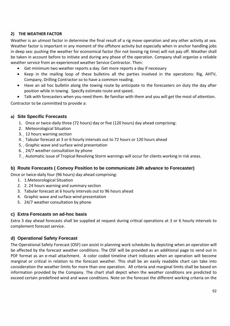
92
2) THE WEATHER FACTOR
Weather is an utmost factor in determine the final result of a rig move operation and any other activity at sea. Weather factor is important in any moment of the offshore activity but especially when in anchor handling jobs in deep sea: pushing the weather for economical factor (for not loosing rig time) will not pay off. Weather shall be taken in account before to initiate and during any phase of the operation. Company shall organize a reliable weather service from an experienced weather Service Contractor. Then:
• Get minimum two weather reports a day. Get more reports a day if necessary • Keep in the mailing loop of these bulletins all the parties involved in the operations: Rig, AHTV,
Company, Drilling Contractor so to have a common reading. • Have an ad hoc bulletin along the towing route by anticipate to the forecasters on duty the day after
position while in towing. Specify estimate route and speed. • Talk with forecasters when you need them. Be familiar with them and you will get the most of attention.
Contractor to be committed to provide a:
a) Site Specific Forecasts 1. Once or twice‐daily three (72 hours) day or five (120 hours) day ahead comprising: 2. Meteorological Situation 3. 12 hours warning section 4. Tabular forecast at 3 or 6 hourly intervals out to 72 hours or 120 hours ahead 5. Graphic wave and surface wind presentation 6. 24/7 weather consultation by phone 7. Automatic issue of Tropical Revolving Storm warnings will occur for clients working in risk areas.
b) Route Forecasts ( Convoy Position to be communicate 24h advance to Forecaster) Once or twice‐daily four (96 hours) day ahead comprising:
1. 1.Meteorological Situation 2. 2. 24 hours warning and summary section 3. Tabular forecast at 6 hourly intervals out to 96 hours ahead 4. Graphic wave and surface wind presentation 5. 24/7 weather consultation by phone
c) Extra Forecasts on ad-hoc basis Extra 3 day ahead forecasts shall be supplied at request during critical operations at 3 or 6 hourly intervals to complement forecast service.
d) Operational Safety Forecast The Operational Safety Forecast (OSF) can assist in planning work schedules by depicting when an operation will be affected by the forecast weather conditions. The OSF will be provided as an additional page to send out in PDF format as an e‐mail attachment. A color coded timeline chart indicates when an operation will become marginal or critical in relation to the forecast weather. This shall be an easily readable chart can take into consideration the weather limits for more than one operation. All criteria and marginal limits shall be based on information provided by the Company. The chart shall depict when the weather conditions are predicted to exceed certain predefined wind and wave conditions. Note on the forecast the different working criteria on the

93
left‐hand side of the table and the Safe, Marginal and Critical status highlighted in color. Also note the defined Critical Limits that are specified by the Client for each specific vessel / rig / platform operation.
e) Satellite Imagery Provider shall be able to supply Satellite Imagery or other appropriate satellite data depending on the operational sea area. Weather specific charts for your operation areas, must be also available. Charts to be customized to meet the specific requirements for pressure data, significant wave data and surface wind data and reflect the forecast model data output at T + X hours ( X = 0,12,24 etc) for a region surrounding operation area. Weather charts shall be available up to T+144 hours in 12 hourly steps and could be attached to every forecast.
f) Hybrid Coordinate Ocean Model – HYCOM HYCOM has been developed as part of a multi‐institutional consortium between academia, government and private industry. It represents the world’s first eddy‐resolving global ocean prediction system with both high horizontal and high vertical resolution. HYCOM, through the use of hybrid coordinate systems, extends the coverage of traditional models by best representing the stratified open‐ocean, un‐stratified seas, and the coastal ocean.
g) Real Time Ocean Forecast System Atlantic – RTOFS RTOFS (Atlantic) is one of a series of ocean forecast systems based on HYCOM. Aiming to establish an operational high resolution (eddy resolving) ocean forecast system for short‐term forecasts (approximately 1‐week) of the Atlantic Ocean with US deep and coastal waters well resolved. RTOFS uses a curvilinear grid favoring the western Atlantic, with the highest resolution of 5 km along the US coastline to 9‐17 km resolution along the European and African coastlines. The operational RT_OFS_ATL presently covers the Atlantic Ocean from 25° S to 70° N.
h) Data only Current forecast The highest resolution model (HYCOM or RTOFS) appropriate to the indented location will be chosen by default. Some locations, such as near river outflows or complex bathymetry, will not be accurately represented by these products and in these cases a more complex solution may be required.
i) Current Advisory Service A higher level service is also available. This is usually undertaken by our in‐house oceanographers which gives the added benefit of an oceanographer’s interpretation of the forecast for the area of interest.
j) Monthly Tidal Prediction Annual tidal predictions can be issued on a monthly supply for any applicable area requested by the Company.
3) WEATHER LIMIT – WHEN IS TIME TO STOP OPERATIONS Weather sensitive operations should be initiated with a clear weather window ahead. Sometime because economic pressure of costly operation or delays along the planned operations we may face the dilemma of when to stop it.

94
In case of bad weather in the middle of an anchor job, this decision shall be taken possibly in agreement between OIM and AHTV Master(s). Detail of this decision shall be punctually recorded on the Vessels and Rigs Log Book as this will be scrutinized later on, when operations will resume end the time lost accounted for. About the captioned question, quite difficult to generalize as different geographical areas have a different approach: what is normal weather in harsh environment (Shetland Island for example) becomes extreme weather in other situation. The particular moment of the operations shall be taken in account: may be continuing and forcing the weather may result less dangerous than stopping abruptly. A Vessel caught in heavy weather while deploying an anchor line may have more difficulties in returning the line on the bolster then going ahead and complete the job. Also the power of the Vessels, the deck features, the water depth of reference, the experience of the Masters and crews will determine the weather limits. Once taken in account all the above, if weather situation worsening and :
a. Crane operator cannot see the deck of the AHTV or cannot safely work because swinging of lifts b. Wind is in excess of 40 Knots c. Waves is in excess of 3 or 4 meters d. Rolling and pitching impairs the capability of Vessels crew to work on deck e. Vessel shall utilize constantly more than 50% of the thruster power to keep the position f. Vessel cannot stretch lines against wind, sea and or against strong Eddy or Tidal currents
Experience says than jointly two of these factors should lead immediately to a halt in the operation, previously securing the Rig if possible. Pushing over the weather may result in a definitive damage to equipment and a serious risk to the personnel working on the deck of the AHTVs.
4) TRAINING, COMPETENCY AND MANNING When considering standards of training and competency, it should be recognized that appropriate simulator training is a valuable tool in attaining and maintaining relevant competencies. Recommended competencies for all roles are detailed below. Trainee Personnel Trainee personnel should always be accompanied by suitably experienced qualified personnel. Regional emergency preparedness Special qualification requirements may apply in areas with regional emergency preparedness. These requirements must be contractually defined, and Ship Owners must ensure that crews always meet them. Anchor handling Due to the nature of A/H operations participating personnel must additionally be familiar with all aspects of such operations as follows: Masters:
• Require relevant expertise and be experienced on the vessel class or design he is aboard. Masters with no previous A/H experience should perform at least 5 rig moves accompanied by an A/H experienced Master, or a suitable combination of rig moves and simulator training, before they may command an A/H assignment. Ship Owner shall document Master’s compliance with this. A/H experience gained in a chief officer role is acceptable. Masters having previous A/H experience as Master or chief officer, but where this is more than 5 years ago, should have an overlap period of at least 14 days with an A/H experienced Master. At least one A/H operation must be performed during this period.
Tow Masters

95
• Actively participated in the execution of at least five rig move operations on a similar MODU type or a suitable combination of rig moves and simulator training. (This should be documented.) Extensive knowledge of all relevant rules and regulations.
• Extensive knowledge of the Rig move plan. • English language capabilities • Participated in the execution of, at least three rig move operations onboard an anchor handling vessel,
or previous experience as AHTS Master or relevant marine experience. Officers:
• Officers require relevant expertise. They shall be familiar with A/H operational guidelines on safety, and with safe use and limitations of equipment.
• Chief Officers or officers in charge of the watch should have previous A/H operations experience of at least 5 rig moves or a suitable combination of rig moves and simulator training. Ship Owner shall document the officer’s compliance with this requirement. If supervising A/H work on deck, the officer must have A/H experience and be competent in A/H procedures and guidelines, A/H equipment set‐up and function, and be familiar with associated hazards and risks.
• Officers working on the bridge during A/H and have tasks that may affect the safety of those working on deck shall be familiar with A/H deck work operations and the associated hazards and risks.
Winch operators:
• Must be competent in the winch operation and safety systems, functions and limitations. Vessel and MODU Owners shall be able to demonstrate necessary training has been given to Winch Operators. A certificate should be issued
Vessel Deck crew:
• Personnel assigned independent work on deck during A/H operations shall be familiar with guidelines and procedures for this, and A/H safety. They should also be familiar with the use of UHF/VHF radio. Able‐bodied seamen with no previous A/H experience must be trained in guidelines, procedures and safe equipment use before assignment to independent A/H work on deck. Document training
Company Marine Representative
• Actively participated in the execution of at least five rig move operations on a similar MODU type or a suitable combination of rig moves and simulator training. This should be documented.
• Extensive knowledge of all relevant rules and regulations, • Extensive knowledge of the rig move plan. • English language capabilities • Knowledge of Operators internal reporting routines and operating procedures. • Participated in the execution of at least three rig move operations onboard an anchor handling vessel or
previous experience as AHTS Master or relevant marine experience. Additional Personnel Any Additional Personnel, such as those listed below, should have relevant experience in role:‐
• Positioning quality controller /Survey Rep. • Positioning Engineer • Mooring Engineer • Marine Equipment Supplier Rep.

96
Crane operators (In addition to Industry certification) Should have:‐
• Experience with crane operation from participation in at least 3 rig moves. • English language capabilities. • Knowledge of the Rig move plan for the operation
DP competence requirements:
• If DP operations are to be carried out within safety zone Masters and mates on board DP‐equipped vessels shall possess necessary competence, experience and certificates for the vessel’s certified equipment class, as specified by its class notation. At all times at least one DP operator on the bridge shall have deck officer certificate of competence.
• If a non‐DP‐certificated person is to operate the DP system they should be supervised by a competent DP operator. They should have completed the basic introduction course in system functions and DP system use at an approved training centre.
Non (Class I and ll) DP systems (Enhanced Joystick) Ship owners must provide training giving Deck Officers good working systems knowledge, as a minimum covering:
• procedures for system operation, especially approaching and settingup on location. • description of the maneuvering systems (propulsion, joystick and reference systems). • engaging or disengaging enhanced joystick facility • selecting appropriate settings for joystick and reference input according to the conditions recovery in
event of failure • limitations of the facility (a capability footprint is a useful aid). • Records of training should be maintained.
Manning General
• The operating company must describe the framework and work scope for the service. Vessel manning is determined from this.
• Sailing periods for vessel crew members shall be agreed between shipping organizations and crew's organizations.
• Crew size must meet flag state's safety manning regulations. Ship Owner shall also ensure manning levels comply with the requirements of the sovereign state of the continental shelf (coastal state) for rest and working hours throughout the assignment.
• Vessels must be manned sufficiently to meet manning and rest requirements to ensure 24 hour operation, where necessary
• Engine room to be manned at all times when vessel is operating inside 500m safety zone and while anchor handling
• Possession and use of alcohol and drugs on board OSVs is strictly prohibited.

CHA PRELA
PRE‐Lmoorown normbe te
a)
There1.2.
In sommoor
abcdefg
Havinabc
APTER 10
AID MOORI
1) PRELALAID Mooriring patternchains shot
mal chaser syrminated w
) When utie are two sit. Cost savi. Special o
About come circumsring/unmooa. Additionb. Specializc. Additiond. Shore bae. Additionf. Rig timeg. Strain on
ng evaluated. There arb. There is . There is
Contract
About sp
0
INGS
AID MOORINngs is the pn of the Rigts to easilyystem to mwith a chase
ilize a Prelatuations whngs perational s
ost saving. tance (to beoring operatnal cost for zed personnnal transporase providenal High Spee necessary n all the log
d all the aboe many welnot big diffes a track otors personn
pecial opera
NGS preparationg of refereny work onlymove the liner stopper p
aid Mooringhere a pre‐l
situations
e carefully etions. But sexpensive mnel to lay anrtation costed with heavecs Anchor connectinggistic set up
ove, an effells in the saerence in wof good exnel, shore b
ations
n of a compnce. Normay with the wes, becauseplate.
g System?aid mooring
evaluated), shall be takemooring eqnd retrieve t vy lifting eqHandling Veg and discon
ective savinme area of water depthxperience abase of refe
plete set oflly the Rig wires of the there are
g system de
pre laid moen in due acuipment onthe moorin
quipment anessel dedicannecting lin
g in rig timeoperation from a weland team wrence.
f Moorings,is stripped e Rig’s lineno more an
eserves to b
oorings mayccount: n rental basng lines
nd space ated only tones
e and well o ll to anothework betw
P
500 1/152NON ROTATIN
P
500 1/152
, laid at a doff the ow
e. As the rnchors to st
be evaluated
y save Rig ti
is
o prelay and
operation ca
r ween Rig, P
PRELAY CON
30
30 - 40 MPENETRATION
2MNG WIRE
A
PRELAY CON
30
30 - 40 MPENETRATION
2M
A
3000 1/915M 3"GROUND WIRE
direction cown anchors aig will conttop the cha
d:
ime during
d retrieve m
an be achie
Pre laying
NNECTED TO
0 0
Anchor Radius 2500 - 2800 M
NNECTED TO
0 0
Anchor Radius 2500 - 2800 M
500 1/152MINSERT WIRE
PO
75 -85 TONSOPERATING
ompatible wand eventutinue to utiaser, each li
mooring line
ved if:
AHTV and
O RIG LINEO RIG LINE
4000 1/1219MOLYESTER ROPE
RIG WIREPAYOUT 20
(610-9150)
G TENSION
97
with the ually the ilize the ne shall
es
Prelaid
Fig. 6Fig. 6
000' - 3000'

98
a. If there is to upgrade a Rig not capable to reach a certain water depth, this cannot be avoided. b. If Drilling Dept. has intention to use Surface BOP in deep water
In the first case (a) special hazop shall be in place, this shall include:
1) the risk of having a riser string much bigger that the Rig has been designed therefore a bigger quantity of mud to be displaced that may exceed the capability of Rig’s mud tanks. A solution could be having always in the field the presence of a stand‐by vessels with empty mud tanks ready to receive excess mud in case for any reason a quick disconnection it may be necessity.
2) The necessity of having a constant monitor of the Riser’s stress thru the monitoring of the surface and
subsurface currents by installing on the Rig an ADCP (Acoustic Doppler Current Profiler).
The second case (b) the possibility is quite negligible.
2) CATENARY and TAUT PRELAID MOORINGS In a Pre Laid System the most common mooring line configuration is the catenary mooring line consisting of chain and wire lines. For deeper to ultra‐deep water, the weight of the catenary mooring line becomes a limiting factor. To overcome this problem, new solutions were developed consisting of inserting synthetic ropes and utilizing Vertical Load Anchor. Lines to be kept in constant tension so to have a taut leg mooring system The major difference between a catenary mooring and a taut leg mooring are:
• the catenary mooring arrives at the seabed horizontally • the taut leg mooring arrives at the seabed at an angle.
This means that a in a catenary mooring the anchor point is only subjected to horizontal forces while in a taut leg mooring the anchor point has to be capable of resisting both horizontal and vertical forces. While in a catenary mooring, the restoring forces are generated by the weight of the mooring line, in a taut leg mooring the restoring forces are generated by the elasticity of the mooring line. An advantage of a taut leg mooring over the catenary mooring is that the footprint of mooring is smaller. Summarizing:
a) A Catenary Mooring Is composed by traditional Drag Embed anchors, Chain and Wires: suitable up to WD 1000 m
• Anchor and first shot of chain arrives horizontally • Has to resist to horizontal forces • Restoring force when line offset is generated by the weight of the mooring lines (chain). • Larger mooring path footprint
Eni has utilized an 800 Mt Water Depth “Cetenary Pre Laid Mooring” composed as follows:
1. 12 Tons Stevpris anchor 2. 700 m 3” chain 3. 1200 m 3.1/8” wire rope 4. 49 tons Surface Buoy (or less according water depth and wire size) to hold the line afloat
b) Taut Mooring System composed by Vertical Anchors (VLA), Wires, Synthetic Ropes: Suitable for over
1000m WD

99
• Anchor and first shot of wire arrives with an angle • Has to resist to vertical forces as well • Restoring forces when line offset is generated by the elasticity of the synthetic ropes elongated up to 5%
of lenght length • minor mooring path footprint
Eni has utilized a 1200/1400 m water depth Tout System composed as follow:
1. 9 Tons Bruce MK 3 VLA (DENNLA) anchor having 12 SqMt of fluke ares 2. 152 m 3.1/8” wire rope connected to the anchor to allow better penetration into the mud 3. 914 m 3.1/8” wire rope 4. 700 m 5.1/8” Polyester Ropes with max elongation c/w shackles and ancillaries (weight in the water
approx 6‐8 Kg/Mt. 5. 152 m 3.1/8” wire rope 6. 20 tons Surface Buoy to suspend the moorings. Polyester Ropes in the water weight 6/8 Kg/Mt.
3) VERTICAL LOAD ANCHORS
In re‐analyzing the concept of a VLA (DENNLA) shall be noted: • DENNLA anchors are fitted with a breakable shear pin calibrated to 60 tons • AHTV deploys the DENNLA anchor with the shear pin intact deployment position • AHTV embed the anchor same as a traditional anchor. As the anchor is fully embedded, AHTV retrieves
work wire/mooring line so to be up right above the anchor. Then applies a pull of +60 tons to break the pin. At this time anchor reaches the working position.
• Once in the working position, anchor is set to resist to uplifting forces and no further embedment is possible hence the rule:
• IT IS THE POWER OF THE AHTV THAT SETS THE VLA ANCHOR TO THE REQUIRED WORKING POSITION Rule of the thumb says that that a 200 tons of bollard pull passes to the horizontal (embedding) component of the anchor no more than 90 tons (less than half of the BP). The remaining 110 tons are lost in the weight of the line and the uplifting vertical components. As the Ultimate Pull Out Capability (UPC or capability to resist to Pull Out Forces) is for a VLA between 2.5 and 3 times the force utilized to set the anchor (90 tons) hence we may consider the anchor may resist to 220/270 tons uplifting forces before the failure. The following figures explains the setting of a line (tout system) utilizing a DENNLA. Note: To avoid damages produced by chafing on the sea bottom, the polyester rope must be kept clear of the seabed at all times.
Utilizing Vertical Load anchors and Taut Moorings: Line chafing against anchor bolsters.
One of the problems the Selected MODU could face is that due to the verticality of the mooring line when utilizing the Taut/VLA System is the fact that line may chafe against the anchor bolster, which have not being designed for the purpose of a vertical line. This problem shall be evaluated with the drilling contractor and the prelaid mooring contractor as the consequences can be very serious if not taken in due account. Eventually this can be solved with utilization of submersible buoys uplifting the mooring line thus reducing or eliminating the chafe. But this is a complication on the mooring operations.

100
a) Installation of a prelaid Line with a DENNLA (VLA) anchor:
Recovery a DENNLA

101
CONNECTING PROCEDURES STEP 1 Once the rig is in position, with the Rig’s anchor line secure in sharks jaw, the anchor‐handling vessel (AHV) will proceed to and deck the buoy (figure step 1). Normally to reach the buoy all the rig line will be paid out, it may be necessary to connect vessel work wires and pay out to reach the buoy. STEP 2 With anchor line and insert wire on the deck of the (AHV), the chaser and the chaser stopper plate is to be installed between the anchor line and the insert wire (the last section of the anchor line connected to the buoy). It is best to keep the chaser against stopper plate if possible. STEP 3 With the chaser taking the weight of the system, the rig will recover anchor line, picking up until there is tension on the line. When sufficient tension is on the line, the AHV will power ahead approximately 20% and the AHV’s jaws will be opened. It is important that the AHV maintain tension on the line at all time while lowering. This is to prevent the chaser from running back up the line and possibly damaging the wire. As this chaser wire is being lowered, the rig will start hauling in the slack in the rigs anchor line maintaining tension on the line at all time STEP 4 When the connection is on deck the short chaser wire will be disconnected and passed back to the rig . This method will be used until the rig is connected on all eight lines. While connecting the first wire the towing vessel will be used to maintain tension on the line
CONNECTING RIG LINE
RUNNING RIG LINE TO MAKE CONNECTIONSTEP 1STEP 1
CONNECTING RIG LINE
PICK UP BUOY AND FIT PWC ASSEMBLYSTEP 2STEP 2
With rig on location distance up to 1500m with WD of 7000ft
CONNECTING RIG LINE
LOWER PWC AFTER CONNECTINGSTEP 3STEP 3
PWC MUST BE KEPT AGAINST PWC STOPPER,
COORDINATION BETWEEN AHV AND RIG REQUIRED
RIG LINE TENSION = ?
AHV WORK WIRE TENSION= ?
CONNECTING RIG LINE
DISENGAGE PWC AND STRIP BACK TO RIGSTEP 4STEP 4

102
DISCONNECTING PROCEDURES STEP 1 With between 150 to 190 Kips of tension on the anchor line, pass the chaser wire to the AHV STEP 2 The AHV will connect the chaser wire to the AHV’s work wire. The AHV will pay out the necessary aMODUt of work wire calculated in order the chaser FALL DOWN FREE TO THE ANCHOR WIRE AND NOT STRIP WITH ANY TENSION STEP 3 When the AHV’s forward movement stops and line tension increases means the chaser has reached the stopper, the AHV’s work wire will be hauled in slowly. The AHV will apply approximately 20‐35% power and continue to recover connection. At the same time, the rig will start slacking the anchor wire to allow the AHV to deck the connection point. Good communication is necessary for this operation. Winch operator and AHV must be in constant communication STEP 4 With the connection point on deck and the insert wire disconnected from the rig wire the chaser will be removed and stored on the AHV STEP 5 The appropriate Buoy assembly is connected and deployed. The rig line passed back to the rig once hauled in This procedure will be repeated until all lines are disconnected.
DISCONNECTING RIG LINE
PASS PWC PENNANT TO AHVSTEP 1STEP 1
DISCONNECTING RIG LINE
DROP PWCSTEP 2STEP 2
DISCONNECTING RIG LINE
ENGAGE PWC AND LIFT CONNECTIONSTEP 3STEP 3
PWC MUST BE KEPT AGAINST PWC STOPPER,
COORDINATION BETWEEN AHV AND RIG REQUIRED
DISCONNECTING RIG LINE
PICK UP BUOY AND REMOVE PWC ASSEMBLYSTEP 4STEP 4
DISCONNECTING RIG LINE
RETURN RIG LINESTEP 5STEP 5

103
A 900 m WD utilized by Eni Indonesia for the drilling Campaign with Transocean Legend. The above described is one of the 4 lines (abreast) that has been buoyed to lift the chain avoiding chafing on the anchor racks. This more for VLA/Taut Systems.
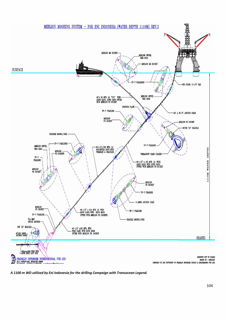
A 1100
0 m WD utilizeed by Eni Indoonesia for thee drilling Cammpaign with Trransocean Leggend.
104

105
Strain on the logistic capabilities of the shore base when dealing with prelaid moorings. The complete Deck of a Supply Vessel in the first picture being utilize to transport only part of pre-laid mooring equipment equipment for the Catenary Mooring (Up to 900 Mt WD)

106
4) EXAMPLE OF EQUIPMENT SPECIFICATION FOR No 2 DEEP SEA MOORINGS (TAUT POLYESTER)
Equip. Specification No Note Vertical Anchor
• Dennla Mk IV or Mk II anchors or equivalent, Weight app 8.5 MT.
Complete with 200MT SWL shackles, Able to work in water depth range 3,000 to 8,000 ft. Anchor Weight: Maximum not to exceed 12 MT but not to be less than 8.5 MT. Anchor parts to include, But not be limited to: VLA, Connecting shackle, Drogue line, shear pins, Special equipment, etc. 3rd Party Certification Agency Approval for Materials and Construction: ABS, DNV or Bureau Veritas. Class certification is a pre‐requisite.
• Shall resist To ultimate Working Loads at 50‐degree line angle from the seafloor for following soil shear strength gradients: a) 880 kips (400 mt) at 50‐dg line pull for 5.25 psf/ft strength gradient
18 Units 2 spares
Polyester Ropes
High tenacity marine finished heavy‐duty high‐grade polyester fiber for continuous deep‐water mooring applications. Size, overall Composition, ultimate Braking load shall be carefully identified and proposed by Contractor according Rig’s specs, environmental study and length of commitment by considering the number of cycles and consequent loss in the original specs. Documentation of the polyester material grade and composition, manufacturer and plant location must be provided by CONTRACTOR Failure to include material manufacturer documentation will be cause for rejection. Outer core: Abrasion resistant cover of heavy‐duty high tenacity polyester mix or equivalent, to be assembled as operationally fit‐for‐purpose for covering and protecting the inner core and filter wrapping as provided in Rope Inner core construction. Required Information: Rope’s torsion limitation accounts for specific fiber rope parameters as attached on both ends to RHRL steel wire rope defined at Item 1.3.5 in this Attachment No.1 How much twist can rope accept without being damaged? Required Information: Provide minimum drum winch diameter to prevent damaging rope, accounts for specific rope parameters Required Information: Provide environmental limitations and concerns associated with rope use, accounts for specific rope
18 x1000 mt 2 spares

107
parameters to include but not limited to : a) Dried sea salt b) Saltwater c) Ambient temperatures d) Submerged temperatures e) UV f) Chemicals g) Pressure To include: Name of rope manufacturer and location of plant, plant contact and telephone number, and list of similar jobs over last 10 years. 3rd Party Certification Agency Approval for Materials and Construction: ABS, DNV or Bureau Veritas. Class certification is a pre‐requisite.
Steel Wires
Specification / Characteristics The Super High Strength Insert Wire Rope Plan shall be specifically designed for mooring application and in general accordance to API‐9A latest edition. It should be robust in construction to withstand multiple deployment and redeployment, be able to resist to crushing and abrasion. The rope shall have superior bending fatigue life with reduced elongation. The rope diameter shall be from 3” to 3‐1/2” diameter with construction of 6x49 or 6x55 right hand ordinary lay with Minimum Breaking load. The Ultimate Breaking Load shall be carefully identified and proposed by Contractor according Rig’s specs, environmental study and length of commitment by considering the number of cycles and consequent loss in the original specs. The rope shall be lubricated internally and externally with marine lubricant like G‐bex etc. The finishing of the rope shall be drawn galvanized and the end fitting should Mooring Socket. Each rope shall have its Rope Identification Tape by manufacturer; the storage reels should be provided with 3rd Party certified lifting or rigging points. 3rd Party Certification Agency Approval for Materials and Construction: ABS, BV, DNV, Lloyds ABS, DNV or Bureau Veritas. Class certification is a pre‐requisite.
No 18 x 1000 Mt
2 spares
Buoys Surface Mooring Buoy, shall remain with good floating free board with 1500 mt of 3.1/2” of wire hanging underneath plus 1000 mt of polyester rope. Must be fitted with radar reflectors and lights for easy identification during the night in marine heavy traffic prone areas. Buoys must be foam filled with minimum of 32 kg / cubic meter low density polyurethane foam. Buoy compartments and thru members to be internally pressure tested with a minimum of
18 Requested
2 spares

108
five (5) psi air for leak testing prior to foam installation. Outside of buoy to be blasted to SA2.5 and coated with Yellow Marine Epoxy System. Bull plugs (for foam filling) should not protrude from Buoy surface. Plugs to be sealed after foam installation. Two (2) each anodes each at about twelve (12) kgs. are to be installed near lower pad‐eye.
Swivels Deep‐water Swivel Minimum Breaking strength High Tensile as rated below, Quenched & Tempered Steel Body Graphite Impregnated Galvanized, High Tensile Steel Body graphite Impregnated Aluminum‐ Bronze Thrust Washer Required Mill Cert & 3rd Party Certification by either Lloyd, ABS, DNV or Bureau Veritas. Class certification is a pre‐requisite.
18 Requested
2 spares
Chaser Stopper
Chaser Stopper assembly c/w 3” chain – MBL tons or to match rig’s MBL Line.
9 Requested 1 spare
Ancillary & jewelry
Connecting Chains, shackles, sockets, kenter links of major and reputed manufacturer in number and size as necessary to assemble 18 working lines plus spares.
Requested as Necessary
Spares as necessary
Spooling Machine
One Unit Hydraulic Spooler suitable for onshore/offshore usage to install and remove polyester rope to from AHV’ s winches Hydraulic spooler, “fit for purpose” to install and Suitable for onshore /offshore usage and fit to handle drums utilized by Contractor to spool and transport poly and steel wires.
1 requested plus availability of back up in short notice
Ultra deep Water Inserts
High tenacity marine finished heavy‐duty high‐grade polyester fiber for continuous deepwater mooring applications. Size, overall Composition, ultimate Braking load shall be carefully identified and proposed by Contractor according Rig’s specs, environmental study and length of commitment by considering the number of cycles and consequent loss in the original specs (as per No 2)
9 requested or 18 requested if ultra deep water are back to back
1 (or 2) spares

109
CHAPTER 11 JACK UP RIGS
1. INTRODUCTION AND BACKGROUND 1.1 SYNOPSIS OF A JACK UP A Jack Up is an offshore structure composed of a hull, legs and a lifting system that allows it to be towed to a site, lower its legs into the seabed and elevate its hull to provide a stable work deck capable of withstanding the environmental loads. A typical modern drilling Jack Up is capable of working in harsh environments (Wave Heights up to 80 ft, Wind Speeds in excess of 100 knots) in water depths up to 500 feet. Because Jack Ups are supported by the seabed, they are preloaded when they first arrive at a site to simulate the maximum expected leg loads and ensure that, after they are Jacked to full airgap and experience operating and environmental loads, the supporting soil will provide a reliable foundation. 1.2 PURPOSE AND DISCLAIMER Jack Up Units are complex structures used offshore in many modes of operation. When using a particular Unit at a given site, it is important to be aware and understand the basics behind the different designs under different conditions. The focus of this primer is a simplified discussion of the various sensitivities of Jack Ups while in the different modes of operation. It is hoped that by increasing the understanding of how Jack Ups work and behave as well as the sources of the loads acting on them, those making decisions with limited information will be better equipped to respond to incidents and reduce their occurrence and/or consequences. Though there are many variations in design and purposes for Jack Ups, this primer focuses many of these discussions on three‐legged Units used for drilling The primer starts by presenting some background and discussions of the basics of Jack Up components analyses. This is followed by sections on Jack Up Components and Configurations, modes of operation, differences between Class approval and site specific assessment, basic analysis, and a discussion of competing aspects of Jack Up design. 1.3 BACKGROUND Jack Up Units have been a part of the Offshore Oil Industry exploration fleet since the 1950’s. They have been used for exploration drilling, tender assisted drilling, production, accommodation, and work/maintenance platforms. As with every innovative technology, Jack Up Units have been used to their operational and design limitations. These limitations include deck load carrying limits when afloat, load carrying capabilities when elevated, environmental limits, drilling limits, and soil (foundation) limits. The reasons for pushing these limits include the desire to explore deeper waters, deeper reservoirs in harsher environments, and in areas where soils and foundations may be challenging or even unstable. Into this arena of expanding Jack Up Units’ capabilities, Industry Groups, Classification Societies, and Flag States have involved themselves in an attempt to Regulate, Codify, and Unify the criteria used to gauge a Jack Up Unit’s capabilities. Without a thorough knowledge of the background of these Regulatory efforts and the science that these efforts rely upon, the average Offshore Industry professional is given practically no useful tools when it comes time to assess, understand, and select a Jack Up Unit to fulfill a particular task or Mission Statement. Often times, a thorough understanding of Jack Up Unit capabilities and “sensitivities” prevents or minimizes the consequences of unexpected “incidents.” This primer is an attempt to assist such individual in understanding the Regulations, science and engineering principles behind a Jack Up Unit’s design and to assist that individual in answering the following questions:
• What are the components of a Jack Up Unit and what are their functions?

110
• What are the relative pros and cons of different types of Jack Ups and their features? • How does the arrangement of a Jack Up affect its function and capability? • What are the loads on a Jack Up, what impact do they have, and how are they evaluated? • What do I need to look for ‐ what makes a Jack Up “sensitive” to loadings? • Who are the parties involved in the Jack Up from design through operation, and what are their roles? • How do I select a suitable Jack Up Unit for my particular application?
This primer does not address commercial issues of Jack Up Rigs. Topics such as Construction Costs, Day Rates, Third Party Equipment, Supply and Crew Boat Costs, etc. are not covered in this primer. 2. COMPONENTS OF JACK UP RIGS AND THEIR FUNCTION 2.1 INTRODUCTION There are three main components of a Jack Up: Unit: the Hull, the Legs & Footings, and the Equipment. This section of the primer describes each of these components and their functions.
2.2 HULL The Hull of a Jack Up Unit is a watertight structure that supports or houses the equipment, systems, and personnel, thus enabling the Jack Up Unit to perform its tasks. When the Jack Up Unit is afloat, the hull provides buoyancy and supports the weight of the legs and footings (spud cans), equipment, and variable load. Different parameters of the hull affect different modes of operation of the Unit. These are described below. In general, the larger the length and breadth of the hull, the more variable deck load and equipment the Unit will be able to carry, especially in the Afloat mode (due to increased deck space and increased buoyancy). Also, larger hulls generally result in roomier machinery spaces and more clear space on the main deck to store pipe, 3rd Party Equipment, and provide for clear work areas. The larger hull may have larger preload capacity that may permit increased flexibility in preloading operations. Larger hulls generally have the negative effects of attracting higher wind, wave and current loads. Since Jack Ups with larger hulls weigh more, they will require more elevating jacks of larger capacity to elevate and hold the Unit. The large weight also affects the natural period of the Jack Up Unit in the elevated mode. The draft of the hull, or the distance from the afloat waterline to the baseline of the hull, has a direct effect on the amount of variable deck load that can be carried and the

111
stability when afloat. The draft of the hull has an opposing relationship with the hull’s freeboard, or the distance from the afloat waterline to the main deck of the hull. Every incremental increase in the draft of a Jack Up decreases the freeboard by the same increment. For units with identical hulls, the one with the deeper draft weighs more. This increased weight could be in the form of lightship weight or variable deck load. Conversely, for Units with identical hulls, the unit with the deeper draft will have less afloat stability than the unit with shallower draft. Perhaps the most influential parameter in a Jack Up unit’s afloat stability is freeboard. For units with identical hulls and leg length, the one with the larger freeboard will have the larger afloat stability margin. 2.3 LEGS AND FOOTINGS The legs and footings of a Jack Up are steel structures that support the hull when the Unit is in the Elevated mode and provide stability to resist lateral loads. Footings are needed to increase the soil bearing area thereby reducing required soil strength. The legs and footings have certain characteristics which affect how the Unit reacts in the Elevated and Afloat Modes, while going on location and in non‐design events. Descriptions of various types of legs and footings follow in Section 3 below. The legs of a Jack Up Unit may extend over 500 ft above the surface of the water when the Unit is being towed with the legs fully retracted. Depending on size and length, the legs usually have the most detrimental impact on the afloat stability of the Unit. The heavy weight at a high center of gravity and the large wind area of the legs combine to dramatically affect the Unit’s afloat stability. For Units of the same hull configuration and draft, the Unit with the larger legs will have less afloat stability. When in the Elevated Mode, the legs of a Jack Up Unit are subjected to wind, wave, and current loadings. In addition to the specifics of the environment, the magnitude and proportion of these loads is a function of the water depth, air gap (distance from the water line to the hull baseline) and the distance the footings penetrate into the seabed. Generally, the larger the legs and footings, the more load wind, wave, and current will exert on them. Legs of different design and size exhibit different levels of lateral stiffness (amount of load needed to produce a unit deflection). Jack Up stiffness decreases with increases in water depth (or more precisely, with the distance from the support footing to the hull/leg connection). Furthermore, for deeper water depths, flexural stiffness (chord area and spacing) overshadows the effects of shear stiffness (brace). Leg stiffness is directly related to Jack Up stiffness in the elevated mode, thereby affecting the amount of hull sway and the natural period of the Unit (which may result in a magnification of the oscillatory wave loads). 2.4 PRELOAD AND SOIL PENETRATION Jack Ups are preloaded when they first arrive at a site to ensure the soil is capable of withstanding the maximum expected footing reaction (either from the extreme storm condition or from the operating condition) without experiencing additional leg penetration or soil failure. The amount of leg penetration is determined by soil properties, vertical reaction of the legs, and footing area. Generally, the larger the footing area for the same vertical reaction and soil, the lower the penetration. The amount of soil penetration should be checked against the footing structural capabilities and scour characteristics of the site. There are various preload techniques such as single‐leg preloading and jacking with minimal air gap that reduce the risk of experiencing adverse effects when rapid penetration (punch‐through) occurs. Soil information and predicted penetration curves should be onboard and understood before making the decision to preload at a site. It is recommended that leg penetrations during preloading be recorded (i.e., generate actual penetration vs. footing reaction curves) and compared against the predicted penetration curves, as this information is invaluable in assessing the quality/validity of the soil assessment and will serve to improve future calculations.

112
2.5 EQUIPMENT
The equipment required to satisfy the mission of the Jack Up Unit affects both the hull size and lightship weight of the Unit. There are three main groups of equipment on a Jack Up Unit, the Marine Equipment, Mission Equipment, and Elevating Equipment.
“Marine Equipment” refers to the equipment and systems aboard a Jack Up Unit that are not related to the Mission Equipment. Marine Equipment could be found on any sea‐going vessel, regardless of its form or function. Marine Equipment may include items such as main diesel engines, fuel oil piping, electrical power distribution switchboards, lifeboats, radar, communication equipment, galley equipment, etc. Marine Equipment, while not directly involved with the Mission of the Jack up Unit, is necessary for the support of the personnel and equipment necessary to carry out the Mission. All Marine Equipment is classified as part of the Jack Up Lightship Weight. “Mission Equipment” refers to the equipment and systems aboard a Jack Up Unit, which are necessary for the Jack Up to complete its Mission. Mission Equipment varies by the mission and by the Jack Up. Two Jack Up Units which are involved in Exploration Drilling may not have the same Mission Equipment. Examples of Mission Equipment may include derricks, mud pumps, mud piping, drilling control systems, production equipment, cranes, combustible gas detection and alarms systems, etc. Mission Equipment is not always classified as part of the Jack Up Lightship Weight. Some items, such as cement units, are typically classified as variable deck load as they may not always be located aboard the Jack Up. “Elevating Equipment” refers to the equipment and systems aboard a Jack Up Unit which are necessary for the Jack Up to raise, lower, and lock‐off the legs and hull of the Jack Up. This equipment is described in more detail in Sections 3.7 and 3.8, below.
3. BASIC JACK UP CONFIGURATIONS There are many components that are common to all Jack Ups; however, differing design and operational philosophies dictate some of the subtle differences among Jack Up Units. The basic differences between Jack Up Units involve the legs, elevating systems, and load transfer philosophy between the hull and the legs. This section of the primer identifies those basic differences, and elaborates on pros and cons of each. 3.1 MAT FOOTINGS VERSUS INDEPENDENT SPUD CAN FOOTINGS Almost all Jack Up Units have footings. Their purpose is to increase the leg’s bearing area, thereby reducing the required capacity of the soil to provide a solid foundation upon which the Jack Up will stand and transfer weight, operational, and environmental loads to the seabed. There are two main footing types: mats and spud cans. Mat footings connect all the Jack Up Unit’s legs to one common footing. Mat footings typically are rectangular structures, flat on the top and bottom, and contain buoyancy chambers which are flooded when the mat is submerged. There are two main advantages of mat footings. First, due to their larger size, mat footings exert a lower bearing pressure on the soil than Units with spud cans. This is beneficial in areas where the soil cannot support high bearing loads. The second advantage is that in the afloat transit mode, mats provide considerable buoyancy, which may translate to increased variable load carrying capability. There are three main disadvantages of mat footings. Mats cannot be used on uneven seabeds or those with large slopes. Sloping or uneven seabeds induce large bending moments on the mat and legs. A mat structure built to withstand such high bending loads would be comparatively very heavy. Mat units also cannot be used on bottoms where there are obstructions such as pipelines, debris, etc. The final main disadvantage of mats is that during the transition from afloat to on‐bottom operations, the mat must be flooded. This flooding sequence must be done carefully so as not to cause large heeling moments or loss of afloat stability of the Unit. When refloating the Unit, the water must be pumped out of the mat, which requires equipment not needed on independent‐legged Units.

113
Units with independent spud can footings have the same number of spud cans as there are legs. Spud cans are typically somewhat conical structures, with sloping tops and bottoms. The sloping top helps in sloughing off mud that may collect on top of the spud can in the event of deep penetration. The sloping bottom helps ensure that there will be some penetration, even in very stiff soils. Spud cans are normally designed to be free flooding when submerged, though they can be pumped dry for internal inspection. There are many advantages of spud can footings. The biggest advantage is that they can be used on a great variety of seabeds. Units with spud cans have operated on seabeds of hard and soft soils, sloping bottoms (though they may be sensitive to large slopes on hard soils), and in areas where there are pipelines or other structures that must be avoided. In addition, spud cans do not require sensitive ballasting sequences or equipment and some rigs can retract the spud cans flush into the hull to permit easy dry transport of the Unit. Units with spud cans exhibit larger bottom bearing pressure and result in increased soil penetrations when compared to mat Units. Because of this high bearing pressure, spud cans leave impressions in areas with soft soils. If another Jack Up Unit later works in the same area, these old spud can impressions may induce horizontal forces on one or more legs if the spud cans tend to slide into the old spud can impressions. Mat footing Independent Legs Spud Can
3.2 CYLINDRICAL LEGS VERSUS TRUSSED LEGS All Jack Up Units have legs. Their purpose is to provide elevation of the hull above the storm wave crest; withstand wave, current, and wind loads; and to transmit operational, environmental, and gravity loads between the hull and footings. There are two main leg types: cylindrical and trussed. Cylindrical legs are hollow steel tubes. They may or may not have internal stiffening, and may have rack teeth or holes in the shell to permit jacking of the hull up and down the legs. Cylindrical legs are currently found on Units operating in water depths less than 300 feet. The newer Units operating in water depths of 300 feet and greater all have trussed legs. The main reason for this is that cylindrical legs require more steel to provide the same resistance to environmental loads and provide the same elevated response as truss legged Units The primary advantage of cylindrical legs is for Units that operate in shallow water as these Units are normally smaller and have less deck area. Cylindrical legs take up less deck area and are generally less complicated requiring less experience to construct than trussed legs. Trussed legs consist of chords and braces. In general, the braces provide the shear capacity of the leg while the chords provide the axial and flexural stiffness. One of the main benefits of the Trussed legs is that they allow for optimal steel utilization and result in lighter stiffer legs with reduced drag loads.

114
3.3 3‐LEGGED VERSUS 4‐LEGGED JACK UPS The great majority of Jack Up Units in the world have no more than four legs, with three being the minimum required for stability. There are some Units built with more than four legs, but these will not be addressed in this primer. Units with 3 legs have the legs arranged in some triangular form. The main advantage of three‐legged Units is that they completely eliminate the need to build extra leg(s). Furthermore, for a given hull size, they can carry more deck load in the afloat mode; and usually have a reduced number of elevating units (pinions, cylinders, etc), resulting in reduced power/maintenance requirements, and less weight. Disadvantages of three‐legged units include the fact that they require preload tankage and they have no leg redundancy. Units with 4‐legs usually have the legs arranged in some rectangular form. Fourlegged Units require little or no preload tanks on board. This is because four‐legged Units can preload two legs at a time using the elevated weight as preload weight. This results in a savings of piping and equipment weights, and more usable space within the hull. Because of the fourth leg, these Units are stiffer in the elevated mode than a three‐legged Unit. This apparent advantage may be offset by the fact that the additional leg adds wind, wave and current loads. In the afloat transit mode, the fourth leg is a disadvantage as its weight causes a direct reduction in the afloat deck load when compared to an equivalent three‐legged unit. 3.4 3‐CHORDED LEGS VERSUS 4‐CHORDED LEGS Trussed legs have either 3 or 4 main vertical structural members called chords. All trussed‐leg Jack Up Units operating today have one of these chord arrangements. In essence, the benefits and disadvantages of three‐ versus four‐chorded legs are comparable in nature to those of three‐ and four‐legged Jack Ups (i.e., overall weight/drag loads and redundancy), except that they do not affect preloading procedures in any way. Cylindrical C C
C CCC L3.5 ELEVATING SYSTEM All Jack Ups have mechanisms for lifting and lowering the hull. The most basic type of elevating system is the pin and hole system, which allows for hull positioning only at discrete leg positions. However, the majority of Jack Ups in use today are equipped with a Rack and Pinion system for continuous jacking operations. There are two basic jacking systems: Floating and Fixed. The Floating system uses relatively soft pads to try to equalize chord loads, whereas the Fixed system allows for unequal chord loading while holding. There are two types of power sources for Fixed Jacking Systems, electric and hydraulic. Both systems have the ability to equalize chord loads within each leg. A hydraulic‐powered jacking system achieves this by maintaining the same pressure to each elevating unit within a leg. Care must be taken, however, to ensure that losses due to piping lengths, bends, etc., are either equalized for all pinions or such differences are insignificant in magnitude. For an electric powered jacking system, the speed/load characteristics of the electric induction motors cause jacking motor

115
speed changes resulting from pinion loads, such that if jacking for a sufficiently long time, the loads on any one leg tend to equalize for all chords of that leg.
3.6 UPPER AND LOWER GUIDES All Jack Ups have mechanisms to guide the legs through the hull. For Units with Pinions, the guides protect the pinions from “bottoming out” on the rack teeth. As such, all Units are fitted with a set of upper and lower guides. Some Jack Up Units, which have exceptionally deep hulls or tall towers of pinions, also have intermediate guides. These guides function only to maintain the rack the correct distance away from the pinions and are not involved in transferring leg bending moment to the hull. Guides usually push against the tip (vertical flat side) of the teeth, but this is not the only form of guides. There are also other forms of guides such as chord guides, etc. Depending on accessibility, some guides are designed to be replaced and are sometimes known as “wear plates.” In addition to protecting the pinions and hull, all upper and lower guides are capable of transferring leg bending moment to the hull to some degree determined by the design. The amount of moment transferred by the guides to the hull as a horizontal couple is dependant on the relative stiffness of the guides with respect to the stiffness of the pinions and/or fixation system (if any). 3.7 OPPOSED PINION CHORDS VERSUS RADIAL PINION CHORDS Jack Up Units that have rack and pinion elevating systems have the interface between the racks and pinions in one of two configurations: two opposed pinions or a single radial pinion at each chord. All jacking systems exert vertical and horizontal forces on the leg at the pinion/rack interface (as the contact area is not horizontal). Opposed pinion systems balance these loads across the chord introducing zero net additional horizontal load applied to the leg bracing. Radial pinions exert a horizontal load on the leg bracing due to the pinion arrangement. Opposed pinion systems have rack and elevating systems on two opposite sides of the same chord, usually resulting in chord sections with double symmetry. The main advantage of opposed pinion systems is good load sharing between pinions of a chord. If pinions are arranged on both sides of the same chord, the overall height of the jacking tower is reduced when compared to pinions arranged only on one side of the chord. If pinions are arranged two high, load sharing between the two pinions is close to 50/50, though not quite uniform. As more pinions are added to the tower, the difference between the pinion with the largest load and the pinion with the least load increases. The final advantage of opposed pinion systems is the reduced height of the jacking tower. This reduced height results in less wind load on the Jack Up Unit as well as reduced weight. Radial pinion systems have rack and elevating pinions on one side of the chord only; thereby resulting in chords with only one plane of symmetry and having the net vertical pinion loads inducing bending of the chord

116
due to the eccentricity. Jack Up Units that have radial pinion jacking systems have two main advantages when compared with opposed pinion systems. First, Radial pinion systems have upper guides located farther away from the lower guide than opposed pinion systems. This is due to the fact that radial pinion systems have a greater overall height. The second advantage of the radial system may be a lower drag coefficient on the leg chord. This, in theory, is because one rack will cause less hydrodynamic drag than two racks. This very much depends on the actual design of the particular leg chords being compared, as designs vary.
3.8 LEG FIXATION SYSTEMS VERSUS NO LEG FIXATION SYSTEMS All Jack Up Units must transfer the environmental, gravity, and operational loads between the hull and the legs. Some Units rely on the elevating pinions to transfer these loads in all modes of operation, while others use the pinions primarily for Jacking operations and use a fixation system to transfer the loads the majority of the time other than jacking operations. Leg bending moment may be transferred from the legs to the hull as a horizontal couple (i.e., opposite forces at the upper and lower guides) or as a vertical couple (i.e., differential chord loading). The proportion of the moment transferred by each of these mechanisms is dependent on their relative stiffness values. Units with leg fixation systems increase the proportion of the moment transferred as a vertical couple. Jack Up Units without a leg fixation system usually require heavier bracings to react the design operating/survival/tow legto‐hull loads. Because the jacking units are the only holding/locking mechanism, care must be taken to ensure they are properly maintained. Furthermore, any loss of jacking/holding capacity may have a cascading effect to the other units and eventually become additional load on the leg structure. While larger braces are capable of taking higher loads before buckling, possibly providing reserve capacity for the braces in non‐design events, they result in larger wind/wave/current loads; which cause these units to have lower environmental ratings than their counterparts that have a fixation system. For such rigs, balancing the strength of chord and brace is important and the brace and chord connections are critical. Jack Up Units that have a leg fixation system require fewer pinions, than Units with no leg fixation system. Furthermore, because of the increased stiffness compared with guides, the majority of the leg/hull moment is transferred as a vertical couple, thereby reducing the required brace scantlings. The reduction in bracing scantlings provides the Unit with a leg that weighs less and has less drag than a Unit with no leg fixation system, which directly translates into increased environmental capabilities for the Unit. Because of this, the capacity to tow with large leg lengths fully retracted is also increased. The fixation system can also serve to support the rig in the event service is required for the jacks. For rigs of such design, the leg bracing is typically the component most prone to damage in the event of accident.

117
4. MODES OF OPERATION OF A JACK UP Jack Up Units operate in three main modes: transit from one location to another, elevated on its legs, and jacking up or down between afloat and elevated modes. Each of these modes has specific precautions and requirements to be followed to ensure smooth operations. A brief discussion of these modes of operations along with key issues associated with each follows. 4.1 TRANSIT FROM ONE LOCATION TO ANOTHER The Transit Mode occurs when a Jack Up Unit is to be transported from one location to another. Transit can occur either afloat on the Jack Up Unit’s own hull (wet tow), or with the Jack Up Unit as cargo on the deck of another vessel (dry tow). These Transit Modes are discussed in more detail below. Main preparations for each Transit Mode address support of the legs, support of the hull, watertight integrity of the unit, and stowage of cargo and equipment to prevent shifting due to motions. Though the Unit’s legs must be raised to ensure they clear the seabed during tow, it is not required that the legs be fully retracted. Allowing part of the legs to be lower than the hull baseline not only reduces jacking time, but it also reduces leg inertia loads due to tow motions and increases stability due to decreased wind overturning. Lowering the legs a small distance may also improve the hydrodynamic flow around the open leg wells and reduce tow resistance. Whatever the position of the legs during tow, their structure at the leg/hull interface must be checked to ensure the legs can withstand the gravity and inertial loads associated with the tow. Field Tow corresponds to the condition where a Jack Up Unit is afloat on its own hull with its legs raised, and is moved a relatively short distance to another location. For a short move, the ability to predict the condition of the weather and seastate is relatively good. Therefore, steps to prepare the Unit for Field Tow are not as stringent as for a longer tow. Most Classification Societies define a “Field Tow” as a Tow that does not take longer than 12 hours, and must satisfy certain requirements with regards to motion criteria. This motion criterion, expressed as a roll/pitch magnitude at a certain period, limits the inertial loads on the legs and leg support mechanism. For certain moves lasting more than 12 hours, a Unit may undertake an Extended Field Tow. An Extended Field Tow is defined as a Tow where the Unit is always within a 12‐hour Tow of a safe haven, should weather deteriorate. In this condition, the Jack Up Unit is afloat on its own hull with its legs raised, similar to a Field Tow. The duration of an Extended Field Tow may be many days. The motion criteria for an Extended Field Tow is the same as for a Field Tow. The main preparations for a Unit to undertake an Extended Field Tow are the same as those for a Field Tow with the additional criteria that the weather is to be carefully monitored throughout the duration of the tow. A Wet Ocean Tow is defined as an afloat move lasting more than 12‐hours which does not satisfy the requirements of an Extended Field Tow. In this condition, the Jack Up Unit is afloat on its own hull with its legs raised as with a Field Tow, but, for many Units, additional precautions must be made. This is because the motion criteria for a Wet Ocean Tow are more stringent than for a Field Tow. The additional preparations may include installing additional leg supports, shortening the leg by cutting or lowering, and securing more equipment and cargo in and on the hull. A Dry Ocean Tow is defined as the transportation of a Jack Up Unit on the deck of another vessel. In this condition, the Jack Up Unit is not afloat, but is secured as deck cargo. The motion criteria for the Unit are dictated by the motions of the transportation vessel with the Unit on board. Therefore, the precautions to be taken with regard to support of the legs must be investigated on a case‐by‐case basis. Generally, though, the legs are to be retracted as far as possible into the hull so the Jack Up hull can be kept as low as practicable to the deck of the transport vessel and to reduce the amount of cribbing support. The other critical precaution unique to Dry Ocean Tow is the support of the Jack Up hull. The hull must be supported by cribbing on strong points (bulkheads) within the hull and in many cases portions of the hull overhang the side of the transportation vessel. These overhanging sections may be exposed to wave impact, putting additional stress on the hull, and if the overhanging sections include the legs, the resultant bending moment applied to the hull (and amplified by

118
vessel motions) can be significant. Calculations should be made to ensure that the hull will not lift off the cribbing with the expected tow motions. 4.2 ARRIVING ON LOCATION Upon completion of the Transit Mode, the Jack Up Unit is said to be in the Arriving On Location Mode. In this Mode, the Unit is secured from Transit Mode and begins preparations to Jack Up to the Elevated Mode. Preparations include removing any wedges in the leg guides, energizing the jacking system, and removing any leg securing mechanisms installed for the Transit thereby transferring the weight of the legs to the pinions. 4.3 SOFT PINNING THE LEGS If an independent leg Jack Up Unit is going to be operated next to a Fixed Structure, or in a difficult area with bottom restrictions, the Jack Up Unit will often be temporarily positioned just away from its final working location. This is called “Soft Pinning” the legs or “Standing Off” location. This procedure involves lowering one or more legs until the bottom of the spud can(s) just touches the soil. The purpose of this is to provide a “Stop” point in the Arriving On Location process. Here, all preparations can be checked and made for the final approach to the working location. This includes coordinating with the assisting tugs, running anchor lines to be able to “winch in” to final location, powering up of positioning thrusters on the Unit (if fitted), checking the weather forecast for the period of preloading and jacking up, etc. 4.4 FINAL GOING ON LOCATION Whether a Unit stops at a Soft Pin location, or proceeds directly to the final jacking up location, they will have some means of positioning the Unit so that ballasting or preloading operations prior to jacking up can commence. For an independent leg Jack Up Unit, holding position is accomplished by going on location with all three legs lowered so the bottom of the spud can is just above the seabed. When the Unit is positioned at its final location, the legs are lowered until they can hold the rig on location without the assistance of tugs. Mat type Jack Up Units are either held on location by tugs, or they drop spud piles into the soil. These spud piles, usually cylindrical piles with concrete fill, hold the Unit on location until the mat can be ballasted and lowered. 4.5 JACKING A mat Unit will jack the mat to the seabed in accordance with the ballasting procedure. Once the mat has been lowered to the seabed, the hull will be jacked out of the water. The Unit then proceeds to Preload Operations (see Section 4.6 below). All Independent leg Units must perform Preload Operations (see Section 4.6 below) before they can jack to the design air gap. Most independent leg Units do not have the capacity to elevate the Unit while the preload weight is on board. For these Units, the next step is to jack the hull out of the water to a small air gap that just clears the wave crest height. This air gap should be no more than five (5) feet. Once they reach this position, the Unit may proceed with Preload Operations. Some of the newer Independent Leg Units do have elevating systems capable of lifting the entire weight of the hull with full preload weight. For these Units, preload is loaded on board while the hull is still in the water. Once full preload is on board, the Unit is slowly jacked out of the water until the preload air gap is reached, no more than 5 feet.

119
4.6 PRELOAD OPERATIONS All Jack Up Units must load the soil that supports them to the full load expected to be exerted on the soil during the most severe condition, usually Storm Survival Mode. This preloading reduces the likelihood of a foundation shift or failure during a Storm. The possibility does exist that a soil failure or leg shift may occur during Preload Operations. To alleviate the potentially catastrophic results of such an occurrence, the hull is kept as close to the waterline as possible, without incurring wave impact. Should a soil failure or leg shift occur, the leg that experiences the failure loses load‐carrying capability and rapidly moves downward, bringing the hull into the water. Some of the load previously carried by the leg experiencing the failure is transferred to the other legs potentially overloading them. The leg experiencing the failure will continue to penetrate until either the soil is able to support the leg, or the hull enters the water to a point where the hull buoyancy will provide enough support to stop the penetration. As the hull becomes out‐of‐level, the legs will experience increased transverse load and bending moment transferred to the hull mostly by the guide. With the increased guide loads, some braces will experience large compressive loads. There are detailed procedures to be followed during such a failure to minimize the structural damage, but these are beyond the scope of this primer. During normal preload operations it is important to keep the weight of the hull, deck load, and preload as close to the geometric center of the legs as possible, as this will assure equal loading on all legs. Sometimes, however, single‐leg preloading is desired to increase the maximum footing reaction of any one leg. This is achieved by selective filling/emptying of preload tanks based on their relative position to the leg being preloaded. Preload is water taken from the sea and pumped into tanks within the hull. After the preload is pumped on board, it is held for a period of time. The Preload Operation is not completed until no settling of the legs into the soil occurs during the holding period while achieving the target footing reaction. The amount of preload required depends on the required environmental reaction and the type of Jack Up Unit. Mat Units normally require little preload. Four‐legged independent Units usually require little or no preload water. This is because four‐legged Units preload two diagonally opposite legs at a time using the weight of the hull. These Units jack to their preload air gap, then lift two legs slightly off the seabed. This causes the Unit to settle on the other two legs. The hull is jacked back up to preload air gap, and the procedure is completed when all four legs have been preloaded to the target footing reaction and no additional penetration takes place. Three‐legged independent Units require the most preload water. For Units that cannot jack with preload, preload water is pumped on board after the hull reaches the preload air gap. If significant settling occurs, the preload must be dumped before the hull is jacked to its preload air gap again, and the procedure repeated until no settling occurs. For Units that can jack with full preload, preload is pumped into the hull while the hull is still in the water. The hull is then jacked up, usually stopping for a short time at certain pre‐arranged drafts. This continues until the hull is at

120
the preload air gap and holds the preload for the holding period. Once the preload is held for the specified time, the preload water is dumped and the Jack Up is ready to be elevated to the operating air gap. 4.7 JACKING TO FULL AIR GAP OPERATIONS Once Preload Operations are completed, the Unit may be jacked up to its operational air gap. During these operations it is important to monitor the level of the hull, elevating system load and characteristics, and for trussed‐leg Units, Rack Phase Differential (RPD) which is described in section 7.7. All of these must be maintained within design limits. Once the Unit reaches its operational air gap, the jacking system is stopped, the brakes set, and leg locking systems engaged (if installed). The Unit is now ready to begin operations. 4.8 ELEVATED OPERATING CONDITION When the Unit is performing operations, no particular differences exist between the various types of Units. Likewise, there are no particular cautionary measures to take other than to operate the Unit and its equipment within design limits. For Units with large cantilever reach and high cantilever loads, extra care must be taken to ensure that the maximum footing reaction does not exceed a specified percentage of the reaction achieved during preload. 4.9 ELEVATED STORM SURVIVAL CONDITION When the Unit is performing operations, the weather is to be monitored. If non‐cyclonic storms which exceed design operating condition environment are predicted, Operations should be stopped and the Unit placed in Storm Survival mode. In this mode, Operations are stopped, equipment and stores secured, and the weather and watertight enclosures closed. If cyclonic storms are predicted, the same precautions are taken and personnel evacuated from the Unit. 5. CLASS APPROVAL VS. SITE SPECIFIC ASSESSMENT There are many parties involved in the safety regime for jack ups. These include Shelf States (national legislation), Flag States (national maritime legislation), Class Societies (class rules), and International Bodies (international codes, e.g, MODU code, etc.). Jack ups may not require a flag but are free to move in international waters when carrying flag. In such case a jack up has to comply with safety regulations of the Maritime Authority in the country whose flag the unit is flying (the Flag State). Jack up drilling units are normally registered with a Flag State Governmental Administration. The role of the Flag Administration, is to implement statutory requirements of the government for registering the unit. Normally, these statutory requirements are derived from internationally agreed regulations developed by the International Maritime Organization (IMO). Today, Flag Administrations largely delegate the tasks of verification of compliance with IMO Conventions to classification societies. Classification societies also issue Loadline, Tonnage and Marpol certificates on behalf of Flag Administrations. Besides classification and statutory requirements, some governments require drilling units, regardless of flag, operating in their territory ial waters to comply with their own safety and pollution requirements. A typical example is in the UK. The UK Health and Safety Executive’s Offshore Division enforces health and safety laws on offshore installations, including jack up drilling units. Classification societies are independent, third party organizations that serve as a verification system for a number of parties who have special interest in the safety and quality of jack ups. These may include regulatory authorities, insurance underwriters, owners, building yards and sub‐contractors, finance institutions, and charterers. 5.1 CLASSIFICATION SOCIETIES Classification is a comprehensive verification service providing assurance that a set of requirements laid down in rules and standards established by the classification society are met during design and construction and maintained during operation of the jack up. The rules and standards ensure safety against hazards to the unit,

121
personnel and the environment. Each classification society, such as the American Bureau of Shipping (ABS), Det Norske Veritas (DNV), Lloyds Register (LR), etc., has its own rules for classification of jack ups. However, many aspects of classification rules of different classification societies are harmonized through the International Association of Classification Societies (IACS). Like ships and other marine structures, jack up drilling units are designed and constructed to satisfy the rules of classification societies. While classification certificates issued by a classification society attest to compliance with such Rules, they also indicate that the unit meets a minimum industry standard for structural and mechanical fitness. To maintain the unit in class, classification societies require periodical surveys to check that the unit is adequately maintained. The class structural scope includes structural strength, materials, welding, fabrication and corrosion protection for jack up hull, superstructures, legs, spudcans, etc. The rig’s ultimate strength in different operation modes, like storm survival, elevated operations, transit, preloading and jacking, etc. are considered. Possible accidental conditions and fatigue are also examined. Design conditions used as bases for the strength approval, such as hull weights, water depths, environmental conditions, etc., are presented in the rig’s operation manual. Assumed foundation fixities may be considered and in such cases included in the operation manual. However, foundation capacity and safety is not part of class structural approval for a jack up rig. JACK UP It is the owner’s responsibility to operate the jack up within the conditions used as basis for class approval, and to confirm that the unit can safely operate at a particular site. Classification rules (e.g. ABS Rules for Building and Classing Mobile Offshore Drilling Units) typically address the following areas:
• Materials of construction and fabrication • Structural integrity • Afloat stability • Safety issue such as structural fire protection and means of escape • Machinery and systems • Periodical survey
Since jack up units are mobile in nature and can be expected to operate in any part of the world, the rules for structures are not associated with the environmental, geotechnical and operational conditions of any specific area. The owner and designer define the environmental and operational conditions to which the unit has been designed; these are the design criteria and theoretical operating envelope of the unit. Designers and owners must assess the desired operating modes and site conditions to ensure they are within the approved envelope. Classification rules require global analyses of the primary structure of the unit in the jacked up and afloat modes of operation. In the transit (afloat) condition leg structures are assumed subjected to defined roll characteristics and gravity bending moment, with correspondingly more demanding criteria in severe storm condition. In addition to the global structural analysis, fatigue analyses are required for classification of all new construction jack ups. Machinery and systems classification requirements are derived mainly from rules for ships, except for specific equipment, such as jacking gears, and safety requirements related to hazards of drilling operations, such as definition of hazardous areas and the installation of electrical equipment in such areas, high pressure piping systems related to drilling, fire safety systems, emergency shutdown systems, and others. Classification rules impose stability criteria for jack up units in all afloat conditions, including temporary conditions, such as lowering leg structures. Two sets of criteria are specified: intact stability and damage stability criteria. While classification of a jack up unit signifies its compliance with a set of minimum standards (Classification Rules), it does not imply that the jack up is adequate to operate in any specific area. In fact, in each case, the owner/operator of the unit should assess the adequacy of the jack up taking into consideration the water depth, environmental, geotechnical, seismic and climatic conditions of the area of operation. For this purpose, industry has developed a standard: SNAME T&R Bulletin 5‐ 5A Guidelines for Site Specific Assessment of Mobile Drilling Units, which can be used as a guide for performing such assessments (See 5.2 Site Specific Assessment below).

122
5.2 SITE SPECIFIC ASSESSMENTS When a jack up is to operate at a particular location, the Shelf State Legislation of the country in which it is to operate will regulate the activity. Industrialized countries are normally well regulated and have comprehensive rules for activities on the continental shelf, while other countries may have less developed regulations and it will be the oil company / owner’s responsibility to define the documentation basis for the site assessment. Both shelf state legislation and oil company / owner’s specification may refer to their own regulations or international guidelines like “Recommended Practice” (RP) for the Site Specific Assessment of Mobile Jack Up Units (SNAME Technical and Research Bulletin 5‐5A) issued by The Society of Naval Architects and Marine Engineers (SNAME) for site assessment of jack ups. In some cases Class Rules and other standards are also considered. As the name indicates, a Site Specific Assessment is an evaluation of the capability of a jack up in the elevated condition to meet a set of standards for structural strength of the jack up and foundation (soil strength of the site) supporting the jack up at a particular site. In general, the rig owner will be given the environmental conditions that must be met, along with the soil information needed to perform the assessment. It is not uncommon for oil companies to have in‐house criteria modifying the SNAME RP to better reflect their risk philosophy. The main objective of the SNAME RP is to document foundation capacities and global structural strength for jack up site operations. In cases where the rigs loads, actual environmental condition and soil conditions fall clearly within the basis for class approval of the structure, it may be that only foundation capacities need to be considered. 5.3 FIELD MOVES Classification rules require that jack up drilling units meet the intact and damage stability criteria outlined in the rules. To meet typical intact stability requirements, jack up units must be capable of withstanding a wind velocity of not less than 36 m/s (70 kn) for field transit and 51.5 m/s (100 kn) in severe storm (ocean tow) conditions. Typically leg strength for transit conditions must meet the following:
• Field Transit – Leg strength is to be developed to withstand a bending moment caused by a 6‐degree single amplitude roll or pitch at the natural period of the unit plus 120% of the gravity moment at that angle of inclination of the legs.
• Severe Storm (Ocean Transit) – Legs are to withstand acceleration and gravity bending moments resulting from the motions in the most severe anticipated environmental transit conditions, together with wind moments corresponding to a velocity of not less than 51.5 m/s (100 kn).
During dry tows, classification societies consider the jack up as cargo on the transport vessel and are not normally requested to review field or ocean transit arrangements. This is normally carried out by Warranty Surveyors. However at the completion of an ocean tow, classification societies usually require a comprehensive survey of the legs, leg to hull connections, the jack house to hull connections, and any other areas deemed to be highly stressed during the tow. Warranty survey companies are often requested to approve wet and dry tow arrangement and weather predictions of transit routes. Areas that warranty surveyors normally review and approve for wet tow are: hold down arrangements of cantilevers and any cargo on the deck. The warranty surveyor also ensures that the jack up meets the classification rule requirements for intact and damage stability. For dry tows warranty survey companies review and approve such things as the motions of the transportation vessel, cribbing, size of towing tug and towlines, and weather en route. The weather en route and motions of the jack up and/or towing vessel are carefully monitored throughout the duration of the tow. 6. JACK UP DESIGN‐‐THE ULTIMATE COMPROMISE In addition to all the drilling equipment and layout requirements, and given the fact that a Jack Up operates in different modes, there are two main opposing disciplines that govern the design of a Jack Up: Naval Architecture and Structural Capabilities. These two disciplines often benefit at the expense of each other.
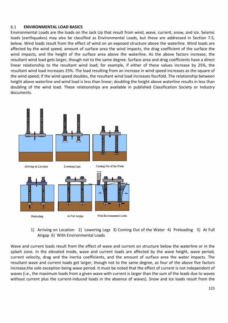
123
6.1 ENVIRONMENTAL LOAD BASICS Environmental Loads are the loads on the Jack Up that result from wind, wave, current, snow, and ice. Seismic loads (earthquakes) may also be classified as Environmental Loads, but these are addressed in Section 7.5, below. Wind loads result from the effect of wind on an exposed structure above the waterline. Wind loads are affected by the wind speed, amount of surface area the wind impacts, the drag coefficient of the surface the wind impacts, and the height of the surface area above the waterline. As the above factors increase, the resultant wind load gets larger, though not to the same degree. Surface area and drag coefficients have a direct linear relationship to the resultant wind load; for example, if either of these values increase by 25%, the resultant wind load increases 25%. The load resulting from an increase in wind speed increases as the square of the wind speed; if the wind speed doubles, the resultant wind load increases fourfold. The relationship between height above waterline and wind load is less than linear; doubling the height above waterline results in less than doubling of the wind load. These relationships are available in published Classification Society or Industry documents.
1) Arriving on Location 2) Lowering Legs 3) Coming Out of the Water 4) Preloading 5) At Full Airgap 6) With Environmental Loads
Wave and current loads result from the effect of wave and current on structure below the waterline or in the splash zone. In the elevated mode, wave and current loads are affected by the wave height, wave period, current velocity, drag and the inertia coefficients, and the amount of surface area the water impacts. The resultant wave and current loads get larger, though not to the same degree, as four of the above five factors increase;the sole exception being wave period. It must be noted that the effect of current is not independent of waves (i.e., the maximum loads from a given wave with current is larger than the sum of the loads due to waves without current plus the current‐induced loads in the absence of waves). Snow and Ice loads result from the

124
effect of snow and ice on structure above the waterline or in the splash zone. There are two types of ice loads, ice from wind/wave driven spray, and pack/floe ice. This document will only address the former. Snow and Ice loads are affected by the thickness and density of the accumulated snow and ice. The primary effects of snow and ice are increased weight on the Jack Up, increased wind area, and increased area exposed to wave and current loads (in the splash zone only). It should be noted that if the Jack Up is exposed to snow and ice loads, it follows that the Jack Up is being exposed to sub‐freezing temperatures. The steel structure of the Jack Up is to be of appropriate material grade for operations in such service temperatures. Snow and ice loads are the only environmental loads that can be reduced by active mitigating efforts, such as continual removal of the accumulated snow and ice from the Jack Up. 6.2 BASICS OF A STABILITY ANALYSIS When a Jack Up is being designed, a stability analysis is used to verify that the hull is capable of carrying the desired amount of leg. A Stability Analysis is performed at a series of afloat drafts to determine the value of the Allowable Vertical Center of Gravity (VCG) for the Jack Up at each of the drafts. Each time the Jack Up undergoes an afloat transit, the Jack Up Owner prepares his afloat loading condition to verify that the combined VCG of all the weights is less than or equal to the Allowable VCG. Two types of Stability Analyses are performed; one with the Jack Up hull intact, and one with the hull damaged. Each of these analyses results in an Allowable Maximum VCG at each draft. For each draft the lowest of these values is the Final Allowable VCG. The main input parameters used to perform a Stability Analysis are hull shape, draft, wind area, hull compartment size (for Damaged Stability Analysis), down flood point location, and Classification/Flag State Rule requirements. A complete Stability Analysis is performed early in the design process, and must be repeated if any of the above‐listed input parameters are changed during the life of the Jack Up. The only exception is for new Rules implemented by Classification Societies after the Jack Up’s keel is laid. If a Classification Society changes its Rules after this point, and the Jack Up does not change Classification Society, it need not comply with the new Rules, but remains instead subject to the rules in place at the time the keel was lain.
6.3 BASICS OF A TOW ANALYSIS After it has been established that the hull has sufficient buoyancy and stability to withstand the target motions, a tow analysis is conducted to verify the structural capacity of the legs and jacking system to withstand the inertia loads associated with motions during tow. Typically, a target motion is defined as a maximum pitch/roll

125
angle at a given oscillating period, acting in conjunction with heave accelerations. The inertia loads increase for larger oscillating angles and lower periods. Though this is a dynamic situation, a tow analysis usually consists of a static analysis representing the maximum inertia loads, using a structural model of the leg and jacking system at its mean (vertical) position. Furthermore, the analyses are typically conducted solely for inertia loads, and do not directly account for wind/wave loads acting on the legs, as these environmental loads were used to determine the maximum roll/pitch angles. Given the noticeable benefits of lowering the legs, tow analyses are usually conducted for various positions of the leg (or Tip of Spud Can), with respect to the hull base line (TOC). For Jack Ups having fixation systems, it is common to have curves of allowable oscillation angles vs. period for the unit with and without the fixation system engaged, for a series of TOC positions. 6.4 BASICS OF AN ELEVATED ANALYSIS A typical Jack Up elevated analysis is a structural analysis on a representative model of the Jack Up at its mean position for a particular water depth, air gap and penetration, for a given environment (wind, wave and current) and elevated weight (i.e., VDL, LCG and TCG). It is usual to assume that all loads from wind/waves/current are horizontal and that they all act in the same direction. While the effects of wind and current are fairly steady, wave loads are oscillatory in nature. Though it is becoming more and more common to perform dynamic analyses, it is standard practice to treat wave loads as quasistatic loads, by using a single critical wave load associated with the crest position that induces the largest overall load (base shear, overturning moment, or some other criteria), and possibly magnifying the load to account for possible dynamic effects (see next section on Dynamic Amplification Factors). Environmental loads are applied in a series of discrete directions and may take advantage of symmetry. Environmental loads arising from wind, wave and current are computed based on the projected area of the components and calibrated coefficients. Application of horizontal forces to an elevated Jack Up can cause relatively small horizontal displacements of the hull (hull sway). Due to the magnitude of vertical loads on the unit, these displacements can have a significant effect on the leg loads. This effect, known as the P‐delta effect, is often accounted for in the elevated analysis of a Jack Up. A typical model for an elevated analysis consists of detailed legs with line (beam/frame) elements for chords and braces, a grillage representing the major structural components of the hull, equivalent members for the spud cans, and jack case/support structures connecting the legs to the hull via pinions/fixation system and upper/lower guides at the proper locations. The connecting elements are usually released in key directions to ensure that the calculated loads act in the appropriate directions. The results of an elevated analysis are stress/load levels for the critical structural elements and are usually compared to allowable values and expressed as utilization ratios (often referred to as unity checks, since a value of 1.0 or lower indicates acceptable levels of loading). It is noted that separate detailed hull and spud can analyses using plate elements are usually conducted for the critical loadings. 6.5 NATURAL PERIOD AND DYNAMICS BASICS As with all structures, Jack Ups have natural response periods. For the elevated mode, the relevant natural periods (i.e., those in the vicinity of the excitation periods) are surge/sway (and possibly yaw), as the heave/pitch/roll periods are quite low. For the afloat mode, the relevant natural periods are heave/pitch/roll, as the surge/sway/yaw periods are extremely large. Typically, surge/sway natural periods in the elevated mode are almost identical. The following factors affect the natural period in the elevated mode:
• The larger the water depth/airgap/penetration, the larger the natural period. • The larger the elevated weight, the larger the natural period. • The larger the rotational soil resistance (fixity), the lower the natural period. • The larger the legs (chord cross‐sectional area and spacing), the lower the natural period.

126
Pitch and Roll natural periods in the afloat mode are slightly different from each other due to the geometry of the hull. Though hand‐calculations can be used to estimate the afloat natural periods, a more effective way that automatically accounts for added‐mass effects using diffraction analysis is often used, once the Unit’s mass characteristics (displacement, VCG and radii of gyration) are known. Pitch/Roll natural periods are sensitive to VCG as well as displacement, but the Heave natural period is only sensitive to displacement. When the excitation loads are periodic in nature, the magnitude of the response in the different modes is dependent on the relative values of the excitation and natural periods. As such, a Dynamic Amplification Factor (DAF) is defined as the ratio of the response to the oscillatory load to the corresponding response to a static load having the same amplitude as the peak oscillatory load. Furthermore, the DAF is dependent on the amount of damping in the system. Damping is usually referenced as a percentage of critical damping (which is a function of mass and natural period). Though Jack Up Units are complex structures, for dynamic purposes they can be approximated reasonably well as simple mass‐spring‐damper systems having a single lumped mass. As such, DAFs are usually approximated using the standard harmonic loading solutions for Single‐Degree‐Of‐Freedom (S‐DOF) systems. Typical damping values for Jack Up Units are in the range of 5‐10% of critical damping. Typically, storm survival waves have periods of 13‐18 seconds while operating waves have periods of 8‐12 seconds. Jack Ups in large water depths have natural periods of 6‐11 seconds in the elevated mode. That means that it is possible to get larger wave‐induced responses from smaller, operating condition waves than from larger waves due to the dynamics of the 6.6 TRADING BENEFITS As is the case with any design, optimization means elimination of excess, resulting in reduced redundancy for non‐design conditions. This section shows how several of the main components of a Jack Up benefit/improve or hurt/diminish the overall capabilities of the Unit. Hull ‐ The bigger the better as far as stability, strength, and operability, but larger hulls have more wind load, are heavier, and require more effort during tow. For three‐legged Jack Ups, the larger the wind loads the larger preload (tanks) requirements. Legs ‐ Large cylindrical legs or trussed legs with large chord spacing are stiffer, but also weigh more and end up reducing hull buoyancy. Trussed legs with large chord spacing require longer braces that, in turn, are less capable in buckling and have more wind/wave/current loading. Furthermore, these legs are heavier and act as huge sails when the Unit is afloat, requiring even more hull buoyancy to meet stability requirements. Leg Spacing ‐ Larger spacing between legs decreases the footing reactions during a storm. This also helps in the event of a given leg slide or rapid penetration during preload; the larger leg spacing results in a smaller out‐of‐horizontal angle before the hull picks up buoyancy and relieves leg load. The greater leg spacing, however, requires a larger, heavier hull. Leg Length ‐ Longer legs permit larger water depth/penetration/airgap and are more flexible, but they also result in larger wind loads, reduced stability and larger inertia loads in the tow condition. Steel ‐ Higher steel grades result in a lighter structure, but they also produce less stiff components and have a lower level of redundancy. This is of particular importance for fatigue‐sensitive areas, as the fatigue life of steel does not increase with its yield strength, but it reduces rapidly with increased stress range levels. Spud Can ‐ As the spud can size increases, the bearing pressure decreases, resulting in lower soil penetration. Larger spud can size, however may require larger leg well openings on the hull, reducing its afloat stability and its capacity to pick up buoyancy forces in the event of rapid penetration. Cantilever Beam ‐ Larger cantilever beams allow the Jack Up to be positioned farther from a fixed structure, but they also result in increased wind loads and large offsets of weight producing large reactions on the aft legs. Brace Size ‐ Increasing the brace diameter of truss legs improves the leg’s capacity to withstand transverse loads, but larger braces have more wind/wave/current load due to higher drag loads.

127
Chord Size ‐ Larger chords with thin members are better for carrying large compressive loads and local bending moment on the legs, but they are more susceptible to localized problems when the brace loads reach high levels. These chords are less compact and stout. Furthermore, these chords have a lower margin of load increase between the elastic and ultimate limits. 7. SELECTED TOPICS ON SENSITIVITIES OF JACK UPS Depending on the general philosophy of the designer, different Jack Ups have their strengths and sensitive areas. Poor understanding of the situation and lack of preparation are often the main cause of otherwise avoidable damage. The sections below present a few of the known sensitivities of various Jack Ups focusing primarily on three‐legged units used for drilling. 7.1 TOW More Jack Ups have been lost at sea during tow than in any other condition. There are many factors that contribute to this, but the main ones are low freeboard, high center of gravity, large wind area, poor hydrodynamic response, and poor speed performance. These topics are addressed in more detail in the following paragraphs. The tendency of any Owner or Operator when moving a Jack Up is to carry as much on board as possible, at as deep a draft as possible. The hull of a Jack Up is essentially a barge or box‐shaped hull. This normally results in low freeboard, such that green water on deck is not an uncommon occurrence, even during a storm that is not severe. If there is any loose cargo on deck, it may break free and damage structures such as hatches, ventilation trunks, etc. If a watertight enclosure gets damaged, green water may flood spaces below deck, putting the Jack Up in imminent danger of capsizing. Additionally, since the Jack Up has a barge‐shaped hull, it cannot sustain transit at a high speed, even if it had its own propulsion system. This eliminates a Jack Up’s ability to out‐run or out‐manoeuvre a storm. In some cases where the towing vessel(s) or towing gear were undersized, Jack Ups have broken free from their towing vessels and wallowed in the storm posing an extremely dangerous situation to personnel on board. Finally, as Jack Up hulls are not ship‐shaped, the benefit gained from “heading into” waves may be minimal at best, and does not significantly reduce severe motions, or green water on deck. One benefit Jack Ups have over other floating vessels is the capability of lowering the legs, thereby easily lowering the VCG, and even reaching a stable foundation to weather storms, if the water depth/seabed permit it. The tall legs of a Jack Up Unit in tow have the doubly negative effect of raising the vertical center of gravity, making the Jack Up less stable afloat, and acting as large sails which, in high winds, increase the heeling effect significantly. The center of gravity of the legs can be hundreds of feet above the waterline, so even slight motions of the hull in waves cause the legs to move like pendulums. Unless the legs are tightly secured at the jack case of leg fixation system, damage can occur to the leg structure, jacking machinery, jack case structure, or even the hull structure itself. 7.2 GOING ON LOCATION In addition to the obvious issues related to debris and the existence of pipelines, when lowering the legs at a target site, it is important to note that different leg/jacking designs have different limiting seastates under which the legs may be lowered. In general, the degree of leg loading as impact takes place can be thought of as a transfer from kinetic energy (proportional to velocity square) to potential energy (proportional to the combined stiffness of the leg, jacking/holding system and soil). Furthermore, it is not only pitch/roll oscillations that affect the intensity of these loads, but heave oscillations are also important. As such, the following factors affect the degree of loading on the leg as first contact is made with the sea bed:
• Period of oscillation ‐ Though small period waves may induce relatively small oscillating amplitudes, the low periods may induce high velocities and accelerations. Furthermore, swells (long‐period waves) are likely to induce one‐to‐one heave responses.
• Soil stiffness ‐ Harder (stiffer) soils result in a larger impact load on the leg.

128
• Water depth ‐ Lower water depth (and therefore higher leg axial stiffness) increases the impact load on the leg. Furthermore, the afloat response of the Unit to waves is dependent on the VCG, which in turn is dependent on the relative position of the spud cans with respect to the hull (TOC).
• Hull shape and draft ‐ Hull shape and draft affect the response of the Unit to waves of different periods and in different directions.
7.3 JACKING ON EXISTING FOOTPRINTS Care must be taken when positioning a new jack up rig at a site previously occupied by another jack up because of the tendency of the spud cans of the new rig to slip into the spud cans holes or “foot prints” left on the sea floor by the previous rig. If there is an overlap of a spud can over an old spud can hole, there is a tendency for the spud can not to penetrate straight into the soil, but instead to slip into the old spud can hole. This movement of a spud can, without a corresponding movement of all the other spud cans in the same direction, will impose a bending moment on the legs. This bending moment can be quite severe and may damage the leg in the preloading or jacking up process or it may reduce the allowable storm environmental load of the rig due to the resulting bend of the leg. When selecting a rig for a platform, it is always best to choose a rig with the same leg spacing as a rig that previously drilled at the platform. However, the effect of previous spud can holes can be mitigated if the new rig is positioned so that the centers of its spud cans are positioned either at the center of the holes left by the previous rig or about 1.5 spud can diameters away for the edge of the holes left by the previous rig. If the rig selected for the platform does not have the same leg spacing as a rig previously at the platform and it is not possible to position the new rig so that its legs either are centered over old holes or 1.5 diameters away from old holes while still reaching all of the required drilling positions, there are two techniques which can be used to minimize the effects of old holes. These techniques are “Reaming” and “Swiss Cheesing”. “Reaming” is a technique by which the leg or legs are sequentially raising and lowering the spud can in the hole left by the previous rig in an attempt to wear away the side of the hole, thereby elongating the hole and creating a new hole center location at the spacing of the legs of the new rig. “Swiss Cheesing” is a method in which a number of large diameter holes (24 to 30 inch diameter) are drilled at the side of an existing can hole in order to degrade the strength of soil at the side of the can hole, effectively enlarging the hole. After all precautions have been taken to minimize the effect of previous can holes, care should be taken in preloading and elevating the new jack up. The following should be observed: a) The relative position of the rig to the platform should be monitored as a movement of a leg into a previous can hole may cause an associated movement of the hull. b) If the rig is of the type that exhibits visible deformation before failure, the Rack Phase Differential (RPD) of the legs should be monitored, as this is a good indication of an external bending moment applied to a leg. c) The noises made by the legs rubbing on the leg guides should be monitored, as an increase in guide noise can be an indication of increased guide forces caused by an external bending moment applied to a leg.

129
7.4 LEG PUNCH THROUGHS When a Jack Up is being preloaded, it is important to be prepared to act in the event of rapid penetration of one or multiple legs. Because of the increased demands on Jack Ups (i.e., larger water depths and higher environmental loads) resulting in higher elevated weights during preload, the consequences of a punch through are depth. When a soil layer is underlain by a weaker soil layer, there is a rapid reduction of soil strength. When the spud can reaches this interface, the weaker soil gives way and the support of the leg moves downward at a faster rate than the jacking system is capable of lowering the leg to maintain the hull level. As such, the hull rotates, the legs tilt and bend, causing the hull to sway. This results in a weight shift relative to the supports, thereby increasing the required footing reaction needed to maintain equilibrium. This process continues until either the soil’s bearing capacity or any hull buoyancy arising from the hull entering the water increase sufficiently to reach equilibrium. Jack Ups of all design types experience punch throughs and their resulting damages to braces, chords and jacking units. The accidental loading resulting from a punch through can lead to several types of leg damage including buckling of the braces, buckling or shearing of the chord, punching shear and joint damage. The extent of possible damage is dependent on the magnitude of the punch through and, more importantly, on the actions taken before, during, and immediately after the punch through. Punch through is an extreme event; therefore, proper management of this event is necessary. Modern rigs with a better guide design along with a proper punch through management system, can minimize some of the risks. The following factors affect the consequences of a punch through, for a given amount of “leg run” (with increased leg bending being an indication of the severity of the event):
• Elevated Weight ‐ Higher elevated weight (i.e., amount of preload on board) results in an increased amount of leg bending.
• Water depth ‐ Greater water depth increases the amount of leg bending. • Airgap ‐ A larger airgap means that it takes longer for buoyancy to start helping and therefore, the
amount of leg bending increases. • Leg spacing ‐ Greater leg spacing decreases the amount of leg bending. It is noted that when the soil
strength versus depth (penetration) curve shows regression in strength over a large enough span, especially if this regression occurs near the maximum footing reaction of the Jack Up, a procedure known as “Swiss Cheesing” can be used to lessen the effects of a punch‐through. The procedure consists of drilling a number of holes through the critical soil layer(s) to reduce the soil strength so that the legs reach past the critical depth at a reduced load level in a more controlled manner.
Punch Trough damages

130
7.5 OTHER SOIL ISSUES (SCOUR, EARTHQUAKE) There are soil issues other than poor bearing capacity to consider when reviewing a Jack Up’s suitability for a given location. This section presents just a few of the main issues. The first is the case where the soil is extremely hard or calcareous. In these cases, the penetration of the spud can will be minimal allowing only a portion of the spud can bottom plate to be in contact with the seabed. In this condition, only that part of the spud can structure in contact with the soil will be supporting the environmental loads, deadweight, and operational weight of the Jack Up. It is extremely important to verify that such partial bearing will not cause damage to the spud can structure. In cases like these, an adequately reinforced tip on the spud can may be advantageous compared to flatbottomed footings. Scour is another problem that occurs in certain locations such as areas with sandy bottoms and high bottom current. In this case, the footing is originally supported over a certain portion of its bottom area during the initial preload operation. Over time, however, high currents may cause erosion under a portion of the footing. When this happens, the bearing pressure increases over the preload value due to loss of support area. Depending on the bearing capacity of the soil, additional penetration or spud can rotation may occur. Additionally, if the footing is not structurally adequate, structural damage may occur. Finally, if scour is severe and over a large enough area, the footing may slide into the depression created. Any of these scenarios can be extremely severe, especially since they occur with the hull at full air gap. Seismic activity (earthquakes, tremors) and its effect on soils must also be considered in certain parts of the world. In extreme situations, seismic activity may induce liquefaction of sandy soils. There is no preparation that can be made to lessen the consequences of this situation. If seismic activity is predicted in a given area, structural analyses should be performed on the Jack Up, based on historical measured events in the area, to determine if it is structurally capable of withstanding the seismic loads and corresponding dynamic effects in combination with other operating and environmental loads. The last soil issue addressed herein is that of bottom obstructions. Part of the process of determining if a Jack Up is suitable for a particular location is to identify bottom obstructions and determine if they will affect the location of the Jack Up’s footings. Bottom obstructions include pipelines, wellheads, fixed platform piles, debris, etc. Prior to a Jack Up’s arrival on site, such obstructions should be surveyed and marked with transponders. Likewise, transponders are typically placed on a Jack Up’s lower legs, so their location can be monitored throughout the Soft Pinning (Section 4.3) and Final Coming On Location (Section 4.4) operations. This will reduce the risk of the Jack Up leg accidentally contacting a bottom obstruction and causing damage. 7.6 GUIDE/RACK TEETH WEAR The legs are restrained in horizontal movement and in rotation by the leg guides. Leg guides may also maintain the allowable position of the elevating pinions with respect to the leg rack. Over time, it is normal to experience wear in both the guides and in the part of the leg that is in direct contact with the guides. This wear in both the leg guides and the leg should be monitored. When the leg guides are excessively worn, they should be replaced. If leg wear should become excessive, the leg should be repaired. ACKNOWLEDGEMENT: JACK UP PRIMER by BASS and OTD/KeppelFels, Copy Right 2005, updated July 1, 2005 - Readers should use the information at their own risk.

131
CHAPTER 12
Dinamic positioning
1) BASIC CONSIDERATIONS Dynamic Positioning (DP) is a technique of automatically maintaining the position of a floating vessel within a specified tolerance by controlling onboard thrusters which generate thrust vectors to counter the wind, wave and current forces. As shown in the picture, the major elements of a DP system include: • Power system: Prime movers and auxiliary equipment, generators, switchboards, cabling, etc. • Thruster system: Thrusters and auxiliary equipment, including main propellers and rudders, associated cabling and thruster control equipment, etc. • Control system: The DP computers and associated software, including position references, vessel sensors, operator interface, power management, etc.
DP Advantages: • Vessel is fully self‐propelled; no tugs are required at any stage of the operation • Setting‐up on location is quick and easy • Vessel is very manœuvrable • Rapid response to weather changes is possible (weather vane) • Rapid response to changes in the requirements of the operation • Versatility within system (i.e. track‐follow, ROV‐follow and other specialist functions) • Ability to work in any water depth • Can complete short tasks more quickly, thus more economically • Avoidance of risk of damaging seabed hardware from mooring lines and anchors

132
• Avoidance of cross‐mooring with other vessels or fixed platforms • Can move to new location rapidly (also avoid bad weather)
DP Désavantages: • High capital and operational expenditure • Can fail to keep position due to equipment failure • Higher day rates than comparable moored systems • High fuel consomption • Thrusters are hazards for divers and ROVs • Can lose position in extreme weather or in shallow waters and strong tides • Position control is active and relies on human operator (as well as equipment) • Requires more personnel to operate and maintain equipment
From the above, it can be seen that DP will not always be the most economic solution. While vessels using moorings have a number of advantages, increasingly DP is the best option for many operations because the seabed is cluttered with pipelines and other hardware, so laying anchors has a high risk of damage to pipelines or wellheads. The option to moor to a platform rather than the seabed is also less frequent, because support vessels have become larger and platforms are not designed for the loads that can be placed in the mooring lines. Nevertheless, there is a risk that a DP vessel makes contact with a platform.
During the 1990s there was a rapid increase in the number of vessels with dynamic positioning systems. Many of these vessels have been designed for DP and integrated control of engines and thrusters, but there are also a large number of conversions and upgrades. The situation is market‐driven and relies on operational efficiency which, in turn, places a high reliability requirement on equipment, operators and vessel managers
Dynamic positioning is concerned with the automatic control of surge, sway and yaw. Surge and sway, of course, comprise the position of the vessel, while yaw is defined by the vessel heading. Both of these are controlled about desired or "setpoint" values input by the operator, i.e. position setpoint, and heading setpoint. Position and heading must be measured in order to obtain the error from the required value. Position is measured by one or more of a range of position references, while heading information is provided from one or more gyrocompasses. The difference between the setpoint and the feedback is the error or offset, and the DP system operates to minimize these errors.
The vessel must be able to control position and heading within acceptable limits in the face of a variety of external forces. If these forces are measured directly, the control computers can apply immediate compensation. A good example of this is compensation for wind forces, where a continuous measurement is available from wind sensors. Other examples include plough cable tension in a vessel laying cable, and fire monitor forces in a vessel engaged in firefighting. In these cases, forces are generated which, if unknown, would disturb the station keeping if unknown. Sensors connected to the cable tensioners, and the fire monitors allow direct feedback of these "external" forces to the DP control system and allow compensation to be ordered from the thruster before an excursion develops.
In addition to maintaining station and heading, DP may be used to achieve automatic change of position or heading, or both. The DP operator (DPO) may choose a new position using the control console facilities. The DPO may also choose the speed at which he wants the vessel to move. Similarly, the operator may input a new heading. The vessel will rotate to the new heading at the selected rate‐of‐turn, while maintaining station. Automatic changes of position and heading simultaneously are possible.

133
Some DP vessels, such as dredgers, pipelay barges and cable lay vessels have a need to follow a pre‐determined track. Others need to be able to weathervane about a specified spot. This is the mode used by shuttle tankers loading from an offshore loading terminal. Other vessels follow a moving target, such as a submersible vehicle (ROV), or a seabed vehicle. In these cases the vessel's position reference is the vehicle rather than a designated fixed location. Basic Design Philosophy A DP system should be able to keep a vessel in position within certain excursion limits under the design environment. Since the consequences of losing station can be serious, DP systems should be designed to have high reliability and a certain amount of built‐in redundancy.
2) POSITION REFERENCE SYSTEMS AND EQUIPMENT a) Position reference. Accurate, reliable and continuous position information is essential for dynamic
positioning. Some DP operations require better than 3m relative accuracy. A DP control system requires data at a rate of once per second to achieve high accuracy. Reliability is, of course, of vital importance, to operations where life and property may be put at extreme risk through incorrect position data.
All DP vessels have position reference systems (PRS), (sometimes referred to as position monitoring equipment or PME), independent of the vessel's normal navigation suite. Four types of PRS are in common use in DP vessels;
1. Hydroacoustic Position Reference (HPR) The principle of position measurement involves communication at hydroacoustic frequencies between a hull‐mounted transducer and one or more seabed‐located transponders
2. Taut Wire, A taut wire is a useful position reference, particularly when the vessel may spend long periods in a static location and the water depth is limited. The commonest consists of a crane assembly on deck, usually mounted at the side of the vessel and a depressor weight on a wire lowered by a constant‐tension winch. At the end of the crane boom angle sensors detect the angle of the wire. The weight is lowered to the seabed and the winch switched to constant tension, or 'mooring' mode. From then on, the winch operates to maintain a constant tension on the wire and hence to detect the movements of the vessel. The length of wire deployed, together with the angle of the wire, defines the position of the sensor head with reference to the depressor weight once the vertical distance from the sheave of the crane boom to the seabed is known.

134
3. DGPS Position Reference System GPS accuracy is not adequate for DP purposes. In order to improve GPS accuracy to levels useful for DP, differential corrections are applied to GPS data. This is done by establishing reference stations at known points on the WGS 84 spheroid (the working spheroid of the GPS system). The pseudo ranges derived by the receiver are compared with those computed from the known locations of the satellites and reference station, and a Pseudo‐Range Correction (PRC) derived for each satellite. These corrections are then included in a telemetry message sent to the ship's receiver by a data link. The receiver then applies the PRCs to the observed pseudo ranges to compute a differentially corrected position. Differential GPS systems are provided on‐board by a service provider. The provider maintains and operates a network of reference stations worldwide and will install receiving equipment on‐board to access the services.
4. Laser‐based systems (Fanbeam and CyScan) and Artemis
DP control systems 'pool', or combine, position reference data from two or more position reference systems. If only one position reference system is enabled into the DP then it is simply checked, filtered and used. If two or more are available, then the system needs to use both equally or according to their individual performance. In all modern DP systems the weighted average option can be selected, whereby individual position references are weighted in inverse proportion to the variance or 'spread' of position data; the higher the weighting for an individual position reference system, the greater the influence of that system in the position calculation. Early DP control systems did not have the capability to learn from the past performance other than by the integral terms of the controller. Modern systems are able to improve station keeping performance by using a Karman filter, which provides a model of recent performance to improve present performance. For any operations requiring DP redundancy (equipment Class 2 or 3 operations) it is necessary to utilize three position references. Two PRSs are not adequate, because if one has failed, contradictory reference data provides an impasse, whereas three systems provide two‐out‐of‐three voting to identify a rogue sensor. Where three PRSs are required, the DPO should choose systems that are different. This reduces the probability of common‐mode failure, where one event may result in a loss of position.

135
b) Heading Reference. The DP vessel's heading is provided by one or more gyro compasses, which transmit data to the DP control system. In vessels where redundancy is necessary, then two or three gyros are fitted. If three gyros are fitted, then the DP system may use two‐out‐of‐three voting to detect a gyro failure, and give an appropriate warning to the DPO. Three gyros are typically fitted in vessels complying with equipment Class 2 or 3. A heading reference may also be available from multiple GPS receivers.
c) Environment Reference. There are three main environmental forces which cause the vessel to move away from her setpoint position and/or heading. They are the forces created by wind, waves and current. Current meters to provide feed forward to the DP control system are hardly ever used by DP control systems, because they are expensive, especially if high reliability is required, and generally the current forces change slowly, so that integral term of the controller is adequate. However, a facility exists in some systems for 'quick current update', or 'fast learn'. This is a function which reduces the time constant of the integral term and allows the mathematical model build‐period to be radically reduced. This is intended to allow the system to better react to rapidly changing tidal conditions or the new
conditions after a large change of heading. The DP control system provides no direct active compensation for waves. In practice, the frequency of the waves is such that it is not feasible to provide compensation for individual waves and the forces are too high. Wave drift forces build slowly and appear in the DP control system as current or sea force. The roll, pitch and heave motions of the vessel are not compensated for by the DP control system, but it is necessary for the DP control system to be provided with accurate values of roll and pitch. This is to allow compensation to be applied to all the various position reference sensor inputs for their offset from the centre of gravity of the vessel. Instrumentation to measure these values is provided in the form of a vertical reference sensor (VRS), vertical reference unit (VRU) or a motion reference unit (MRU). The MRU measures accelerations by the use of linear accelerometers and calculates inclination angles. A recent development is the provision of a system which utilizes two or more DGPS receivers with antennae mounted some distance apart. The GPS fixes and motion‐sensors provide data on vessel position, heading, roll, pitch and heave values. This is able to provide a reference for position and heading as well as motion in and about each axis. All DP systems have wind sensors. This data is used to calculate wind‐induced forces acting upon the vessel's hull and structure, allowing these forces to be compensated before they cause a position or heading change. Typically, a wind sensor consists of a simple transmitting anemometer, usually of the rotating‐cup type. The direction of the wind is important for vessels needing to wind or weathervane, or find the minimum power heading. A correct assessment of this heading is vitally important to some vessels, e.g. the shuttle tanker and floating production vessels, which are reliant upon finding the best heading to maximize uptime. The wind sensors are important because large changes in wind speed or direction can cause major disturbances in the positioning if they are not selected or shielded. The wind feed‐forward allows an immediate compensatory thrust to be applied in direct proportion to the change detected in the wind speed and/or direction. Many DP control systems also have a wind compensation facility within the manual (joystick) control function, providing the operator with an environmentally‐compensated joystick control option. d) Power system. Central to the operation of any DP vessel are the power generation, supply and
distribution systems. Power needs to be supplied to the thrusters and all auxiliary systems, as well as to the DP control elements and reference systems.

136
The thrusters on a DP vessel are often the highest power consumers on board. The DP control system may demand large changes of power due to rapid changes in the weather conditions. The power generation system must be flexible in order provide power rapidly on demand while avoiding unnecessary fuel consumption. Many DP vessels are fitted with a diesel‐electric power plant with all thrusters and consumers electrically powered from diesel engines driving alternators. A diesel engine and alternator is known as a diesel generator set. Some DP vessels comprise part diesel direct‐drive thrusters and part diesel electric plant and motor‐driven thrusters. A vessel may have twin screws as main propulsion driven direct by diesel engines and bow and stern thrusters electrically driven, taking power from shaft alternators coupled to the main diesels or from separate diesel generator sets. The DP control system is protected against a mains power failure by the inclusion of an uninterruptible power supply (UPS). This system provides a stabilized power supply that is not affected by short‐term interruptions or fluctuations of the ship's AC power supply. It supplies the computers, control consoles, displays, alarms and reference systems. In the event of an interruption to the ship's main AC supply, batteries will supply power to all of these systems for a minimum of 30 minutes.
e) Propulsion Systems. The DP capability9 of the vessel is provided by her thrusters. In general, three main
types of thruster are fitted in DP vessels; main propellers, tunnel thrusters and azimuth thrusters. Main propellers, either single or twin screw are provided in a similar fashion to conventional vessels. In DP vessels where such main propulsion forms part of the DP system, propellers may be controllable pitch (cp) running at constant rpm8 or variable speed. DC motors or frequency‐converter systems enable variable speed9 to be used with fixed‐pitch propellers. Main propellers are usually accompanied by conventional rudders and steering gear. Normally, the DP installation will include control and feedback of the rudder(s). Some DP vessels are fitted with modern hi‐lift high efficiency rudders which enhance the vessel's transverse thrust aft.
Note: The GLONASS system (the Global Navigation Satellite System) is the Russian counterpart to the American GPS, being similar in design and operation. The system was initiated with the first satellite launches in 1982, and by 1996, 24 operational satellites were in orbit. However, this number has not been maintained and the number available has, at times, been inadequate for good positioning. The principles and practice of position determination with GLONASS are identical to that of GPS, using pseudo‐range measurement from time and ephemeris data transmitted from the satellites. The higher orbital inclination of GLONASS satellites (65°), compared to the GPS constellation (55°), results in better satellite availability in higher latitudes. The limited satellite availability precludes the use of GLONASS as a continuous position reference for DP. A number of combined GPS/GLONASS receivers are available. These have the effect of increasing the number of usable satellites within view of the observer.
3) FAILURE MODE AND EFFECT ANALYSIS (FMEA)
Failure modes and effects analysis (FMEA) should be conducted for floating vessels with a DP 2 or DP3 system. Failure modes to be considered in the FMEA should include the following:
• The sudden loss of major items of equipment • The sudden or sequential loss of several items of equipment with a common link. • Control and monitoring instabilities and failures, and methods of detection and isolation • Faults that can be hidden until another fault occurs DP systems should be designed so that, as far as is
reasonably possible, there are no common single‐point failures. The DP system FMEA should be proved in sea trials, as far as is reasonably practicable; to demonstrate the effects of the various failure modes and to ensure that both equipment and procedures are in place to safely cope with failures.

137
4) GUIDELINES FOR DESIGN, TEST AND MAINTENANCE
Detailed guidelines for design, test, and maintenance of DP systems can be found in the IMO document MSC Circular 645, Guidelines for vessels with Dynamic Positioning Systems (Reference 15). It defines vessel redundancy into three equipment classes, where Equipment class 1 vessels have the least redundancy, and vessels complying with Equipment class 3 have the most redundancy. In this context ‘equipment’ refers to all the equipment (power, control, and references), together with its location/layout on the vessel, that goes to define the degree of redundancy. Equipment Class definitions are: • Class 1: Loss of position may occur in the event of a single fault. • Class 2: Loss of position should not occur from a single fault of an active component or system such as generators, thrusters, switchboards, remote controlled valves etc. Static components such as cables, pipes, manual valves etc. should be adequately protected against accidental damage. • Class 3: Loss of position should not occur from any single failure including a completely burnt fire subdivision or flooded watertight compartment. Using these classifications and the results obtained from the FMEA, it is possible to allocate the vessel with an equipment class notation. Selection of a DP vessel with its inherent redundancy or class should be based on a risk analysis for the particular type of DP operation. The risk analysis should take into account the risks involved with specific operations such as drilling, diving, flotel services, heavy lifting, pipe laying, floating production, shuttle tanker, etc. The particular risk analysis is likely to take into account some of the following: • The time to reach a safe situation, or recover from the immediate danger, • Speed of loss of position (drift‐off, drive‐off, or a large excursion), • Environmental limitations, • Operational procedures, • Human factors etc. The risk analysis can be general and cover different working situations and types of work. However generic assumptions and principles should be considered for each project, location, and procedure to ensure the analysis is valid and/or changes are made to maintain its validity and applicability.
a) Determination of Station‐Keeping Capability ‐ Basic Considerations. A holding capability analysis should be performed to determine whether a DP system can maintain the position of a floating vessel within an acceptable watch circle under the operating environment. This analysis should be performed for new designs as well as for individual operations. Two methods can be used to analyze the holding capability of a DP system. A time domain system dynamic analysis is normally performed for new system designs and critical operations, especially those in shallow water. For routine operations in deepwater, a simplified method addressing only the mean environmental forces can be used.
b) DP Operator. Specially trained personnel are required to operate the DP system with its sophisticated
electronic equipment. Guidelines for training DP operators can be found in the IMO document MSC Cir. 738 “The Training and Experience of Key DP Personnel”. The DP operator is in charge to judge whether there is enough redundancy available at any given moment of the operation. To qualify as a DP operator generally the following path should be followed:
1. a DP Induction course 2. a minimum of 30 days seagoing DP familiarization 3. a DP Advanced course 4. a minimum of 180 days watch keeping on a DP ship 5. a statement of suitability by the master of a DP ship

138
When the watch keeping is done on a Class 1 DP ship, a limited certificate will be issued; otherwise a full certificate will be issued. The DP Training and Certification scheme is operated by a recognized institution. References : IMCA M 140, Specification for DP Capability Plots, August 1997. Introduction to Dynamic Positioning

139
CHAPTER 13 The Bourbon Dolphin Case History
FORWARD While struggling to set anchor # 2 for the drilling rig Transocean Rather on the Rosebank field, halfway between the Shetlands and the Faroe Islands the AHTV Bourbon Dolphin capsized with the loss of eight lives. In the wake of the tragic loss of a modern anchor‐handling/tug/supply (AHTS) vessel on a routine job, the Norwegian government appointed an inquiry commission to establish the full chain of events that led to the calamity. The report, published on March 28, 2008, did not point to any specific reason for the loss, but found deficiencies in the procedures and safety management with all involved parties. The full evaluation of these events is for personnel involved in these operations is a valuable lesson in order not to repeat similar mistakes. In particular the correct sizing and characteristics of AHTV selected and contracted to perform these activities shall be carefully evaluated at the early stage of the planning and contractual and phase by taking in due account the weather, the water depth, the characteristics of the mooring components.
“hope for the best and fear the worst” because sometimes things can go really bad.
1) THE INCIDENT
On Friday 12th April 2007 the Anchor Handling Tug Supply (AHTS) vessel Bourbon Dolphin was engaged in anchor handling operations for the semi‐submersible drilling rig Transocean Rather in the Chevron Operated Rosebank oilfield to the west of the Shetland Islands. For the rig move, Transocean relied on the British consultant Trident. Because the complicated operations during the Rig Move in North Atlantic, five AHTV were contracted for the job: Olympic Hercules, Highland Valiant, Vidar Viking, Sea Lynx, and Bourbon Dolphin. The Rig Move was controlled by a Tow Master appointed by the Operator working in collaboration with the OIM (Offshore Installation Manager), the “Captain” of the Rig. The mooring system of the rig consisted of 8 mooring lines and anchors, with each mooring leg being made up of a18 tons Stevpris anchor, 900m of 84mm chain insert chain kept in the Vessel’s chain Locker, 920m of 76mm Rigs own chain and 1725m of 96mm Rig’s own wire. This system had been decided on so as to ensure the rig maintained position in this exposed location on the edge of the Atlantic, with long lengths of chain used to ensure that there would be no uplift of the mooring from the seabed causing the anchor to be disturbed. A prelaid mooring system, was discounted due to problems being experienced previously with this system in this kind of exposed location. The semi‐submersible drilling rig Transocean Rather was being moved onto the second drilling location in the Rosebank oilfield. The operation to anchor the rig at the previous location and the move to the new location had taken longer than expected, this was due to adverse weather conditions and difficulties encountered during the anchor recovery operation at the previous location. Mooring equipment and J hook chain chasers, which are basically a large metal hook for hooking onto submerged chain or wire, had been damaged. At one stage the Bourbon Dolphin was unable to break out an anchor by herself and the Olympic Hercules had to assist using a J hook, the anchor was eventually freed but the J hook and other equipment were damaged. When the rig arrived at the second drilling location 4 anchors, known as the primary anchors, of the 8 fitted were deployed almost simultaneously to make the rig stable on location, then the remaining 4 anchors, known as the secondary anchors, were deployed in diametrically opposed pairs. The last pair to be laid were anchors 6, then 2. The running of No. 6 anchor by the Olympic Hercules (250 Tons of Bollard

140
Pull) was fraught with difficulties. The current experienced by the vessel whilst running the anchor out on to an anchor position bearing 160°(t) from the rig was believed to be over 2.5 knots, coupled with a wind of around 30‐ 35 knots, both setting to the north north east / north east, and a significant wave height in the region of 3.5m, with a maximum of 7m. With these environmental forces acting against her the vessel ended up over 700m off the planned anchor track, and was not able to maintain station using her side thrusters alone. It was only after the Vidar Viking came to her assistance and grapnelled the chain and took some of the mooring weight, and the rig paid out some of the anchor wire, that the Olympic Hercules was able to execute a turn using her propellers, rudders and thrusters such that she could proceed back to the west towards the anchor drop point. It was reported that whilst this vessel executed her turn, that due to the weight of the mooring chain, its large angle of attack to the centreline of the vessel and the rapid turn into the current, that she heeled over 12°. Even earlier during the deployment of anchor no.3 by the Bourbon Dolphin as the primary vessel it was reported by that vessel that the weight of the chain on her gypsy during deployment was too great therefore the Vidar Viking was deployed to grapnel the chain between the Bourbon Dolphin and the rig whilst the chain was deployed and the anchor over boarded from the Bourbon Dolphin. The Bourbon Dolphin was designated the primary vessel for the running of the final anchor no.2, with the Highland Valour to assist, on an anchor track of 340°(t) from the Transocean Rather in a water depth of around 1100m, which as for anchor no. 6 was going to place the current on the vessels port side (while it was on starboard side to Hercules on No 6) running towards the north north east / north east. For this task an 18t Bruce anchor was on the port side lashed to the crash rail on the Bourbon Dolphin’s main deck. The plan was for the rig to pass the end of her 920m x 76mm chain to the vessel which would secure it on deck, the rig would then pay out this chain while the vessel moved away along the anchor track, and once this was all paid out the rig would then change to the 96mm wire. The vessel would then connect the 900m x 84mm wire in her chain locker to that from the rig and pay this out; once this was complete the anchor would be connected to the end of the 84mm chain, along with a chasing collar placed around the mooring chain and connected to the vessels work wire. The anchor would be lowered to the seabed whilst held in the chasing collar, with the vessel paying out the work wire while getting in position. Once the anchor had been landed on the seabed in position the vessel would move back towards the rig, heaving on the work wire and sliding the chasing collar along the rig chain and then rig wire prior to passing the pennant attached to the chasing collar to the rig where the end of the pennant would be secured on deck. During this operation the assisting vessel was to first grapnel the chain 300m from the Bourbon Dolphin to take the weight while she was overboarding the anchor, then move and grapnel the chain 300m from the connection to the rig wire whilst the anchor was being lowered to the seabed. Whilst the Bourbon Dolphin was running out over the stern the chain insert from her rig chain locker, it was noted the vessel was drifting off the planned anchor track to the east, and was therefore instructed by the rig to move back towards the anchor track. The Bourbon Dolphin reported she was having difficulty maneuvering back to the anchor track due to the weight of the mooring chain hanging from her stern. This, coupled with the prevailing environmental forces was limiting her maneuverability even though she was using her thrusters and main engines at near maximum capacity, therefore the ‘Highland Valour’ was instructed to assist by grapneling the chain and taking some of the weight. At this time it was reported that the engine room on the Bourbon Dolphin requested the bridge to reduce the load on the thrusters as these were starting to get hot, this request was made several more times but not granted. At 14.45, all the anchor chain had been run out from the Bourbon Dolphin and the Highland Valour commenced grapneling to take some of the weight of the mooring from the Bourbon Dolphin so she could maneuver and proceed back to the anchor track as she was now 560m off track. The grapneling operation involves the vessel lowering a wire with a four pronged grapnel attached and fishing for the chain, so as to lift it vertically to reduce the weight of the mooring hanging from the stern of the other vessel, making it easier for that vessel to maneuver back to the planned anchor track. At the second attempt the Highland Valour managed to attached her grapnel to the mooring chain, upon which she experience high tension on her winch, whilst the Bourbon Dolphin
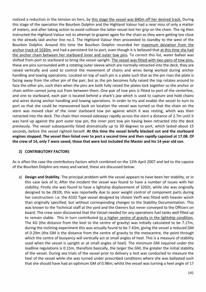
141
noticed a reduction in the tension on hers, by this stage the vessel was 840m off her desired track. During this stage of the operation the Bourbon Dolphin and the Highland Valour had a near miss of only a matter of meters, and after taking action to avoid collision the latter vessel lost her grip on the chain. The rig then instructed the Highland Valour not to attempt to grapnel again for the chain as they were getting too close to the already laid anchor line no.3. The Highland Valour then proceeded to standby to the west of the Bourbon Dolphin. Around this time the Bourbon Dolphin recorded her maximum deviation from the anchor track of 1020m, and had a persistent list to port, even though it is believed that at this time she had the anchor chain between her starboard inner and outer tow pins. To correct this list, water ballast was shifted from port to starboard to bring the vessel upright. The vessel was fitted with two pairs of tow pins, these are pins surrounded with a rotating outer sleeve which are normally retracted into the deck, they are raised vertically and used to control the movement of chains and wires being worked during anchor handling and towing operations. Located on top of each pin is a plate such that as the pin rises the plate is facing away from the other pin of the pair, but as the pin becomes fully raised the top rotates around to face the other pin, such then when the pins are both fully raised the plates lock together so the anchor or chain within cannot jump out from between them. One pair of tow pins is fitted to port of the centerline, and one to starboard, each pair is located behind a shark’s jaw which is used to capture and hold chains and wires during anchor handling and towing operations. In order to try and enable the vessel to turn to port so that she could be maneuvered back on location the vessel was turned so that the chain on the stern was moved clear of the inner starboard tow pin against which it was resting, which was then retracted into the deck. The chain then moved sideways rapidly across the stern a distance of 2.7m until it was hard up against the port outer tow pin, the inner port tow pin having been retracted into the deck previously. The vessel subsequently listed dramatically up to 30 degrees to port, which lasted about 15 seconds, before the vessel righted herself. At this time the vessel briefly blacked out and the starboard engines stopped. The vessel then listed over to port a second time and then rapidly capsized at 17.08. Of the crew of 14, only 7 were saved, those that were lost included the Master and his 14 year old son.
2) CONTRIBUTORY FACTORS
As is often the case the contributory factors which combined on the 12th April 2007 and led to the capsize of the Bourbon Dolphin are many and varied, these are discussed below:
a) Design and Stability. The principal problem with the vessel appears to have been her stability, or in
this case lack of it; After the incident the vessel was found to have a number of issues with her stability; Firstly she was found to have a lightship displacement of 3202t, while she was originally designed to be 2810t, this was reportedly due to poor weight control of component parts during her construction: i.e. the A102 Type vessel designed by Ulstein Verft was fitted with heavier winch than originally specified, but without corresponding changes to the Stability Documentation. This was known to the Technical staff at the yard and the Owners but never conveyed to the Officers on board. The crew soon discovered that the Vessel needed for any operations fuel tanks well filled up to remain stable. This in turn contributed to a higher centre of gravity in the lightship condition. The KG (the distance from the keel to the centre of gravity) was initially calculated to be 7.17m, during the inclining experiment this was actually found to be 7.43m, giving the vessel a reduced GM of 0.29m (the GM is the distance from the centre of gravity to the metacentre, the point through which the centre of buoyancy will vertically act at small angles of heel. This is a measure of stability used when the vessel is upright or at small angles of heel). The minimum GM required under the loadline regulations is 0.15m, therefore basically, the larger the GM, the greater the initial stability of the vessel. During sea trials of the vessel prior to delivery a test was conducted to measure the heel of the vessel while she was turned under prescribed conditions where she was ballasted such that she should have had an optimum GM of 0.98m; whilst the vessel was turning a heel angle of 17

142
degrees was measured. The test was later repeated using less engine power and a smaller rudder angle and then approved. Subsequent to these tests the vessels stability was approved by the vessel flag state. Although the vessel was only in service a short time before she was lost, operational experience found that the vessel had to operate with large quantities of bunker fuel onboard so as to maintain adequate stability, and had previously experienced a large unexpected angle of heel whilst engaged in a towing operation. All these elements were precursors to the fact that the stability of the vessel could have been an area of deep concern.
To calculate the stability condition on the vessel a load computer was fitted, however, this had not been checked and approved by the Classification Society, and should not have been in use. The documentation for the load calculator was subsequently found to be satisfactory after the incident, although it was never tested onboard to see if it was functioning correctly. The instructions for Master in the Stability Book were found to generic and did not contain any instructions specific to the vessel, particularly the fact that the roll reduction tank should be empty during anchor handling operations. AHTS’s are designed with a large beam in relation to their draft so as to give the vessel a large GM as they are designed with a very low freeboard aft to facilitate anchor handling operations. However, a large GM makes the vessel very stiff and prone to a more violent rolling motion, in order to reduce this a roll reduction tank is fitted to reduce the static stability. These tanks are usually the full width of the vessel and work by reducing the GM due to the large free surface effect of the water in this tank moving from side to side as the vessel rolls. This tank is believed to have been in use during the anchor handling operation, therefore reducing the GM. In addition to the 18t anchor sitting on her main deck, the storage winch located high above the main deck, just below the level of the bridge was, at the time of the incident, loaded with 1700m of 77mm wire, therefore placing a heavy weight high above the deck, both of which raised the centre of gravity still further. Analysis of the expected ballast condition based on all available evidence, including the presumption that the roll reduction tank was in use gives the vessel a GM of 0.89m, upon departure from Lerwick, however, she did not comply with all the load line stability requirements. After departure the stability condition changed due to the vessel deploying one of the anchors from her deck, deploying both chains from the chain lockers below decks, which had subsequently been filled with ballast, and she had also used bunkers and fresh water. At this stage the GM was calculated to be 0.95m, however the vessel still did not comply with the minimum stability requirements, even before any other factors, such as the heeling lever applied by the anchor chain, or dynamic movement due to environmental forces are taken into account. Allowing for an angle of attack of the chain from the centerline of the vessel of 25° with a tension of 126t gives a GZ curve (the curve indicating the positive stability of a vessel) with a range of positive stability of 40° with deck edge immersion occurring at 15°. Even assuming the roll reduction tank was not in use the vessel is still not found to be comply with the minimum stability requirements in this condition. Once the starboard inner towing pin was retracted and the chain moved over to the port outer tow pin, and allowing for a tension of 126t at a 40° angle of attack the GZ curve has a range of positive stability of 34° with the vessel listed to 9°, with deck edge immersion occurring at 15°. Assuming a worst case scenario of a 60° angle between the anchor chain and the vessels centerline (which is what is believed to have been the angle at the time of her capsize as captured on footage from the rig), and a line tension of 180t. In this situation the vessel is listed to 12° with deck edge immersion occurring at 15° and a range of positive stability to only 31°. As can be seen, in a static situation the vessel has a very small aMODUnt of residual stability, however, in this case she was subject to dynamic forces whilst lying in a sea with a significant wave height of 3.5m, and as soon as water came on deck at 15° and the deck edge immersed, due to the large superstructure forward, as the deck of a supply vessel immerses the centre of buoyancy moves forward causing the vessel to trim by the stern, causing the vessels

143
waterplane area to reduce and a further reduction in righting levers, leading to a rapid loss of stability and capsize.
b) Rig Move Planning. Several areas of concern were found in the planning of the rig move; principally the choice of mooring system selected and the installation method, the method used for calculating the necessary bollard pull and winch capacities, and also the lack of any Hazard Identification and Risk Analysis prior to operations commencing. The rig move procedure was also found to be lacking in that weather limitations were not specified in line with the requirements of interested parties. In addition no pre‐rig move meeting was held prior to the operation where all interested parties were represented. Although no pre‐rig move meeting was held the rig move procedure was presented to each vessel individually, the meeting between the then Master of the Bourbon Dolphin and the representative from the company which had written the document lasted about 1 hour. The Master onboard at that time reported that he had stated that his vessel was not suitable for the operation due to the fact that a bollard pull of 194t had been calculated as being necessary to break out the anchors from the seabed, whereas the capacity of the vessel was only 180t. The Master therefore subsequently believed he would only be used as an assisting vessel engaged in grapnel work.
c) Vessel selection. Vessels are normally marketed in this industry with their maximum bollard pull,
which for the Bourbon Dolphin was 194t, in reality her continuous bollard pull was only 180t. The vessels propulsion machinery consisted of 4 main engines arranged in pairs driving 2 controllable pitch propellers. In addition the vessel was fitted with a single tunnel thruster and a retractable azimuth thruster forward, and two tunnel thrusters aft. Each propeller shaft was also fitted with a shaft generator to provide power to drive the thruster motors and the hydraulic
system for the winches. Therefore although the vessel was rated at 180t bollard pull, excessive use of the thrusters would have put demands on the shaft generators that would have reduced the power available to the main propellers, possibly dropping the available bollard pull down to 125t. The bollard pull requirement for the weight of the mooring system alone in the rig move procedure was 160t. This was a great deal higher than the bollard pull available to the ‘Bourbon Dolphin’ as she battled to get the vessel back to the track using her thrusters and propellers. Therefore the vessel was chartered when at best her available bollard pull could have been considered as borderline for the task of anchor handling for this particular operation. In addition, when vessels were being assessed for their suitability for the rig move it was found that the winch capacity specified was too low for the dynamic forces which could have been expected during the operation.
d) Other contributing factors. • The winch emergency release had been activated at the time of the incident but the speed of pay
out was noted to be only about 12m/min, when it should have been up to 40m/min. Most personnel on anchor handling tugs are of the belief that these emergency release buttons will lead to an instantaneous release of the chain or wire, when that is not the case. Although it was activated on the Bourbon Dolphin, the wire and chain were only paid out at about 12 m/min, which was not enough to stop the vessel being capsized by the mooring line.
• On the Bourbon Dolphin, the experience of the bridge team, particularly in deep water anchor
handling work was found to be lacking. More experience on the part of the crew may well have helped to prevent the escalation of the events which led to the capsizing.

144
• The handover between the outgoing Master and the new Master, who had not been on the vessel before, lasted only about 1 and a half hours. The vessel subsequently sailed for the 135 mile passage to the Transocean Rather to commence the rig move.
• Previous external audits of the ISM system had not identified that there was no procedure in the
Safety Management System for anchor handling, even though it is a requirement that the Safety Management System should have detailed procedures for all key operations.
• It is debatable whether the running of No.2 anchor should have been started. Although the
environmental conditions were marginal those involved did not believe they were such that operations should be suspended. However, due to the difficulties encountered by the larger more powerful vessel the Olympic Hercules whilst running No.6 anchor it could be argued that the running of the final anchor should have been delayed until conditions were more favorable. Once the Bourbon Dolphin started to have difficulties and was nearly upon the adjacent mooring line again, it could be argued that the operation could have been stopped and options for running the anchor assessed, possibly using a larger vessel or the operation suspended until conditions improved.
• In the Commission opinion, the operations were characterized by major failures in several areas,
not only on the Vessel, as described above, but also on the rig. Whereas the Vessel was very active in her attempt to to get anchor N° 2 into the correct place, the Rig adopted a passive observer role. The most noticeable were:
the drifting during the deployment of anchor N° 6 was not evaluate and communicated to the OIM
the operation begun in marginal weather conditions the operation did not follow the written procedure prescribed for deployment of anchor no. 2
drifting was observed from the rig at an early point, but towmaster did not ask explanations
drifting continued and increased without any questioning or explanation given or requested
causes and consequences of drifting not considered the request of assistance from another Vessel without risk assessment grapnelling unsuccessful two vessels nearly collided the OIM was not given current information and did nothing to keep himself uinformed
3) RECOMMENDATIONS
Following the investigation into the incident a number of recommendations were made to attempt to ensure that a similar incident does not occur in the future, these are detailed below.
• A very probable development from this will be the inclusion in a vessels stability book of anchor handling specific stability conditions and situations that prove the stability of the vessel is adequate. In addition the vessel specific information in a stability book will be more specific to the actual vessel, rather than the standardized generic information which is provided to different vessel types at present, and therefore not truly reflecting the vessel specifically or communicating specific areas of concern.
• Personnel involved in anchor handling operations should undergo more simulator training for these operations including feedback to the operator in the simulator regarding the consequence of
145
actions undertaken during the operation. In addition maritime training establishments have been recommended to include anchor handling and towing stability concerns in the course of training.
• Vessels bollard pull certificates should contain not just the continuous bollard pull, but also indicate the reduction in bollard pull due to the use of shaft generators at their full loading. Also it is recommended that there is a statutory requirement for a quick release function for winches for the crew to use when there is an evident danger of a casualty occurring.
• In addition personnel involved in anchor handling and winch operators should undergo formal training, as at present there is no statutory requirement for this, and the possibility of certification for this training should also be looked into.
• A further consideration that was raised was for an additional emergency exit from the engine room in the hull flat bottom, in addition to those that are already built on these vessels to the main deck; needless to say this would be a technically challenging concept to incorporate.
• Due to the fact that only one liferaft was released automatically and reached the surface of the six fitted to the vessel, it was recommended that thought be given to how these could be fitted such that they would release and float free and inflate clear of the vessel in the event of a capsize. Likewise, the EPIRB which was mounted on the Monkey Island above the bridge did not release, and the stowage of this item also needs to be
investigated to ensure that it releases and floats clear in the event of a capsize. • The mandatory requirement for the fitment of voyage data recorders on vessels of greater than
3,000 GRT should be extended to smaller vessels and rigs as such data would have been useful in this incident, especially the VHF radio conversations where there has been subsequent contention about what was said.
• The length of time for the handover of personnel should be specified by operators in their Safety Management System, especially when crew are joining a vessel they are not familiar with, so as to ensure that they are sufficiently informed about the vessel and its characteristics prior to the departure of the relieved crew member.
• Planning and the rig move plan should also be improved, with the plan being operation specific, provided to all parties well in advance of the operation and an onshore meeting help of all critical personnel. Risk assessments must also be conducted for the overall operation and also for the operations to be performed on each vessel. In addition the rig move plan should specify attention zones along planned anchor tracks, where if the vessel deviates from the track it is to be brought to the attention of the rig and the reasons explained why the vessel cannot remain within the zone, and suitable measures taken to rectify the situation. The lack of clear weather criteria in the rig move procedure was also criticized, as these did not agree with the industry standards for this part of the world or the requirements of the oilfield operator.
• The risk assessments used onboard AHTS vessels for these operations mostly focus on the dangers of the anchor handling operation from the perspective of what is to be done on the working deck. Little attention is paid to the dangers affecting the actual vessel and it is recommended that this is addressed and included in pro‐forma risk assessments used onboard prior to operations commencing.
End

146
CHAPTER 14
Long tow between two locations
• Planning Jack Bates Tow from Noth Sumatra to East Borneo.
Whahat follows is the moving of Jack Bates performed during the Contract with Eni Indonesia. It is merely for didactic purpose to illustrate the content of an Ocean Tow Procedure, by keeping in account all the responsibilities and risks.
Emerald to BSN-1 1256m (4121ft) Average WD to Nominal water depth 840m (2756ft)
JACK BATES Moored Semisubmersible
This Rig Move Procedure has been reviewed by ENI Exploration Indonesia and Transocean Indonesia and is approved for the Jack Bates rig move to the BSN-1 location as per Rig Move Procedure Revision 0.0
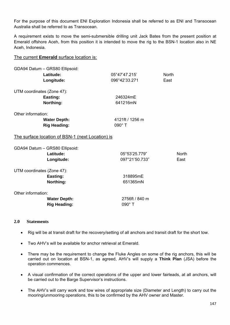
147
For the purpose of this document ENI Exploration Indonesia shall be referred to as ENI and Transocean Australia shall be referred to as Transocean.
A requirement exists to move the semi-submersible drilling unit Jack Bates from the present position at Emerald offshore Aceh, from this position it is intended to move the rig to the BSN-1 location also in NE Aceh, Indonesia.
The current Emerald surface location is: GDA94 Datum – GRS80 Ellipsoid: Latitude: 05°47’47.215’ North Longitude: 096°42’33.271 East UTM coordinates (Zone 47):
Easting: 246324mE Northing: 641216mN Other information:
Water Depth: 4121ft / 1256 m Rig Heading: 090° T
The surface location of BSN-1 (next Location) is GDA94 Datum – GRS80 Ellipsoid: Latitude: 05°53’25.779” North Longitude: 097°21’50.733” East UTM coordinates (Zone 47):
Easting: 318895mE Northing: 651365mN Other information:
Water Depth: 2756ft / 840 m Rig Heading: 090° T
2.0 Statements
• Rig will be at transit draft for the recovery/setting of all anchors and transit draft for the short tow. • Two AHV’s will be available for anchor retrieval at Emerald.
• There may be the requirement to change the Fluke Angles on some of the rig anchors, this will be
carried out on location at BSN-1, as agreed, AHV’s will supply a Think Plan (JSA) before the operation commences.
• A visual confirmation of the correct operations of the upper and lower fairleads, at all anchors, will
be carried out to the Barge Supervisor’s instructions.
• The AHV’s will carry work and tow wires of appropriate size (Diameter and Length) to carry out the mooring/unmooring operations, this to be confirmed by the AHV owner and Master.

148
• The two AHV’s assigned to the Jack Bates will be the Far Sound and the Far Sword.
• An opportunity will be taken between each anchor, to re-tension the vessel work wire, this re-
tensioning will be conducted to the Masters specification and may not necessarily occur at the cross over.
3.0 Preamble 3.1 General The purpose of this document is to ensure that the Jack Bates rig move operation to the BSN-1 location, is conducted in a safe and efficient manner. All key personnel shall be fully briefed by the Towmaster prior to the commencement of operations, to ensure a full understanding of these procedures. This meeting will be documented. These approved procedures shall be followed as closely as circumstances permit, having due regard for the limitations of the unit and its assisting vessels. Should any deviation/change from these procedures be deemed necessary, the ENI Senior Drilling Supervisor shall be advised immediately. Due consideration must be given to any and all effects of such a deviation or change, a deviation/change form is to be completed and duly signed, (page 30) All rig move vessels will be issued with a copy of this rig move procedure prior to the commencement of the operation. The vessel Masters will be fully briefed and are required to review the procedure and comment accordingly. A pre-rig move meeting will be held at the ENI Office Jakarta (prior to) and also onboard the rig, prior to the commencement of operations, where all key personnel, as described in Section 3, shall be fully briefed to ensure a full understanding of these procedures. During the meeting the rig move procedures, bathymetry charts, Site Survey reports, tidal height predictions, near surface current predictions, navigational hazards, radio channels and weather predictions shall be discussed, ENI will ensure adequate weather forecasting for the duration of the of the rig move to Emerald. Prior to the commencement of anchor operations, weather forecasts shall be obtained and a suitable weather window identified to allow each stage of the operation to be safely completed without interruption. All operations will have a pre job meeting and THINK plan (JSA) conducted prior to the work being performed. Where non-routine or unplanned mooring operations are required, either by the rig or the AHV’s, then a written THINK plan (JSA) will be required to be completed by the concerned parties prior to the commencement of that activity. AHV Masters will confirm their vessel(s) safe stability and also that their vessel(s) are ready in all respects for rig move operations on a 24 hour basis. Chain & wire markings shall be checked and refreshed where necessary. All personnel directly involved with the anchor chain recovery and deployment operations shall be aware of the markings on the chain and what the markings represent. Rig personnel will inspect all PCP’s and handling slings at rig end. AHV personnel will inspect all PCP’s and handling slings at vessel end. AHV’s may be supplied, from the rig, with spare equipment such as, pennants, split pins, shackles and lead’s as required by the AHV Master.

149
Prior to the commencement of the rig move, a comprehensive Pre-Move Planned Maintenance procedure is to be undertaken on all windlasses/winch’s and other associated equipment involved in anchor handling operations, by the Mechanical, Electrical and Barge Marine Departments. A list is to be faxed to the Rig Manager upon completion of the PM tasks conducted and deficiencies repaired, before operations commence. The Chief Electrician and PMS are to be on call at all times that anchor windlasses/winch’s are being utilised, to ensure adequate technical supervision and support.
4.0 Personnel Responsibilities
The following descriptions of personnel responsibility refer to the KEY personnel who will be involved in the rig move and mooring of the semi-submersible drilling unit Jack Bates from the Emerald location to the BSN-1 location. 4.1 ENI Company Representative
• Will advise the Transocean O.I.M. when operations on the departing location are complete to the satisfaction of the ENI Company, and that the rig move may commence.
• Will notify all concerned parties, well in advance, not less than two (2) weeks before, of the intention
to move the unit, this to ensure that adequate planning for the move takes place and all concerned are fully informed and procedures instated.
• Will liaise with the O.I.M. as necessary to ensure ENI work plans are implemented correctly.
• Will endorse the completion of all work activities and accept when the rig is properly positioned and
moored on the new location.
• Will ensure that appropriate government, port state, approvals for the move have been obtained.
• Will provide survey equipment and personnel to accurately position the rig within the positional tolerances requested.
4.2 Transocean Offshore Installation Manager (O.I.M.)
• Will at all times have full responsibility for the integrity of the unit and the safety of all personnel on board.
• When advised by the ENI Representative(s) that the rig has been accepted for the drilling program,
he will decide when it is safe and practicable to commence rig-move operations within the limits of the units Marine Operations Manual.
• Will forward an intention to move to all relevant parties and government bodies.
• Will issue a departure notice to RCC Djakarta and will confirm with all stakeholders.
• Will confirm notification to RCC, and other relevant parties.
• Will confirm Departure and Arrival times have been submitted the appropriate authority.
• Confirm that the Helicopter Company has been advised of the rig move, for emergency
requirements.
• Will ensure that the Navigational Bridge is continually manned by certified and competent Watch

150
keepers.
• Will delegate responsibility, in writing, with regards who is in charge of the tow when underway, be it the Towmaster or the Tow Vessel Master, said responsible person shall then reply, in writing to the O.I.M., of their intention to accept the responsibility.
• Will ensure that adequate Passage Planning is in place, in good time, taking into account the
operational safety radius of the Helicopters and will also ensure that enough adequately trained personnel are available for the operation of the rig anchor winches on a 24 hour operational basis.
• Will ensure that one (1) anchor is decked and inspected at recovery stage of rig move, as per
requirements, anchors chains PCC’s and jewellery will be inspected as per attached sheet. 4.3 Transocean Barge Marine Supervisor
• Will ensure deployment of sufficient and competent rig crews for the safe and efficient conduct of rig-move operations.
• Will be responsible for the correct operation and availability of associated mooring and rig moving
machinery and equipment.
• Will liaise directly with the Transocean O.I.M. and Towmaster, regarding marine matters. He may also pass instructions to the vessels regarding anchor handling and towing operations.
• Will ensure pre-move operational maintenance and checks are conducted in an efficient and timely
manner.
• Will ensure that appropriate notifications regarding the rig move are made to governmental and agency bodies as defined by controlling legislation, these to be made in a timely manner and not less than Twenty Four (24) hour’s before last anchor on the Bolster.
• Will maintain a good open line of communication with the O.I.M. Company Representative and
TowMaster on all issues or concerns pertaining to the rig move
• Will ensure that one (1) anchor is decked and inspected (if required) at recovery stage of rig move, as per requirements.
• Will ensure that a thorough inspection of all sea fastening’s is carried out prior to mooring and
towing operations.
4.4 Rig Positioning Surveyor(s) • Will liaise with the Transocean Towmaster and ENI Drilling Supervisor, with regard to navigation
equipment status and position confidence.
• Will be responsible for the proper operation of positioning equipment.
• Will be responsible for providing constant data showing the position of the unit at all times during the rig move.
• Will be responsible for providing data showing the position of all anchors as deployed. This will be
verified with the Towmaster and ENI Drilling Supervisor, to ensure it is accurate at the time anchoring operations commence.

151
• Will ensure that all relevant field data is displayed on the navigation screen as appropriate.
• Will perform system checks to prove navigation system confidence prior to commencement of the rig move and at intervals during the rig move operation.
• Will maintain detailed logs of all movements of the unit, from commencement of the move from the
BSN-1 location.
• Will be responsible for reporting any positioning equipment failures. 4.5 Vessel Masters
• Will be responsible for the safety of their Crew and their Vessel and when towing, for the duration of the Tow.
• Will, along with the Transocean TowMaster plan a passage to BSN-1, taking into account
navigational hazards/obstacles and will plan the passage for the safest most direct route.
• Will inform the O.I.M., in writing, of his intention to take command and responsibility of the tow, as required by the O.I.M.
• Will ensure deployment of sufficient crew to allow for 24 hour operations to be carried out in the
safest most efficient manner, where necessary, rig move extra’s will be brought on board the vessels, in a timely manner in order to assist in the operations and in the management of fatigue.
• Will ensure that all on board are fully conversant in the rig moving operations and procedures, will
inform the relevant parties on the Barge/MODU of any inexperienced crew members, be they Deck Officer, Engineer Officer or Deck Rating.
• Towing Vessel Master will promulgate all appropriate notifications (navigational warnings) to all
Local and National Government Agencies in a timely manner.
• Will ensure that the Navigation of His/Her Vessel is carried out with due regards to the International Rules for the Prevention of Collisions at Sea and will ensure that all charts, Publications and Instruments pertaining to the safe navigation and passage of the vessel are on board and in order.
• Will ensure that the Stability of the vessel is within stipulated criteria, with due regard to stability
whilst anchor handling with heavy loads at the stern quarters and beam, in all weather.
• Will ensure that full risk assessments, job safety analysis and tool box meetings are conducted prior to commencement of operations.
• Will ensure that all relevant equipment required for the operation is on board and fully operational
and will inform the unit management team of any deficiencies with regards work wire (length and condition), shackles, lead shot, split pins etc.
• Will ensure that all vessel machinery is fully operational and in good order, any breakdowns or
deficiencies in vessel operating machinery will be reported to the rig unit management team, in order that appropriate remedial actions may be taken.
• Will not hesitate to inform the unit management, in a timely manner, of any concerns he may have
with regards the rig move operation.
• Will ensure that his vessel has sufficient Fuel, Lube Oil, Potwater and Provisions to carry out the move in a safe and seamanlike manner.
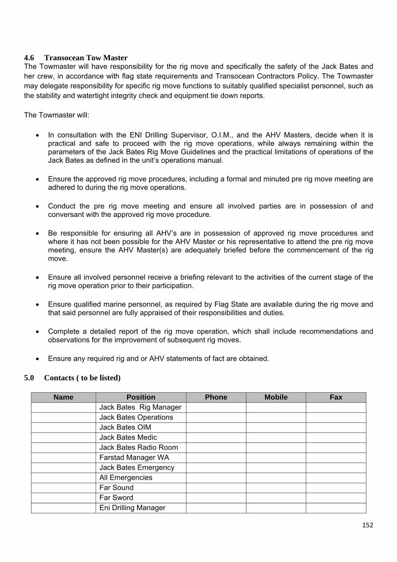
152
4.6 Transocean Tow Master The Towmaster will have responsibility for the rig move and specifically the safety of the Jack Bates and her crew, in accordance with flag state requirements and Transocean Contractors Policy. The Towmaster may delegate responsibility for specific rig move functions to suitably qualified specialist personnel, such as the stability and watertight integrity check and equipment tie down reports. The Towmaster will:
• In consultation with the ENI Drilling Supervisor, O.I.M., and the AHV Masters, decide when it is practical and safe to proceed with the rig move operations, while always remaining within the parameters of the Jack Bates Rig Move Guidelines and the practical limitations of operations of the Jack Bates as defined in the unit’s operations manual.
• Ensure the approved rig move procedures, including a formal and minuted pre rig move meeting are
adhered to during the rig move operations.
• Conduct the pre rig move meeting and ensure all involved parties are in possession of and conversant with the approved rig move procedure.
• Be responsible for ensuring all AHV’s are in possession of approved rig move procedures and
where it has not been possible for the AHV Master or his representative to attend the pre rig move meeting, ensure the AHV Master(s) are adequately briefed before the commencement of the rig move.
• Ensure all involved personnel receive a briefing relevant to the activities of the current stage of the
rig move operation prior to their participation.
• Ensure qualified marine personnel, as required by Flag State are available during the rig move and that said personnel are fully appraised of their responsibilities and duties.
• Complete a detailed report of the rig move operation, which shall include recommendations and observations for the improvement of subsequent rig moves.
• Ensure any required rig and or AHV statements of fact are obtained.
5.0 Contacts ( to be listed)
Name Position Phone Mobile Fax Jack Bates Rig Manager Jack Bates Operations Jack Bates OIM Jack Bates Medic Jack Bates Radio Room Farstad Manager WA Jack Bates Emergency All Emergencies Far Sound Far Sword Eni Drilling Manager

153
Eni HSE Manager Eni Operations Support
6.0 Safety and Communication 6.1 Safety Although anchor handling is defined as being a routine operation, it is by nature also hazardous. The mooring components are heavy, and the equipment used in performing the operation is working under high tensile loading. To outline the safety hazards involved with the operation it will be the responsibility of the O.I.M. to ensure that PRE-JOB MEETINGS and THINK PLANS are held prior to commencement, prior to any shift changes, or prior to effecting changes resulting from a deviation to the original plan. The THINK PLAN and HAZARD ASSESSMENT format will be used during the process and as a minimum will include review and discussion on the following items:
• Clarification that the rig-move procedures have been reviewed, understood, and agreed by all parties and that the requirements outlined in any Sim-Ops manual have been met.
• Clarification of personnel “competency” and authorisation to operate machinery. • Responsibilities of each crew member involved in the operation • Confirmation that fixed and portable communication equipment to be used in the operation have
been checked and that appropriate channels have been allocated. • Chain of command and lines of communication are fully understood. • Equipment limitations with respect to speed and specifically Safe Working Loads. • Keeping areas behind, in front of, and under moving equipment clear of personnel. This relates
specifically to the Anchor Winches and Main Cranes. • Hazards of handling anchor chain and wire cables.
6.2 Communication It is imperative that lines of communication and responsibility have been clearly defined and are understood by all concerned. It will be the responsibility of the O.I.M. to ensure that these actions are completed prior to commencement of the operation. Specific attention will be made to the interface requirements of passing and recovering the anchors and anchor pennants between the rig and the AHV’s. The O.I.M. will accept, or suitably delegate responsibility, to ensure that a competent person is present on the deck while passing, or recovering the anchor pennant to/from the vessel. This person will be equipped with portable VHF communications, and will be in direct contact with the Anchor Winch Operator, the Crane Operator, the AHV Captains, and the Jack Bates Barge Control Room. His immediate responsibility will be in co-ordinating and ensuring that the anchor pennant transfer process is conducted safely and within the equipment limitations. The process of passing the anchor pennant between the rig and the AHV must be undertaken with extreme caution, as this operation is conducted with the rig crane whip-line hoist, which has a limited rating. Further, due to the operating radius of the crane while handling anchor pennants, the boom Safe Working Load rating is at it’s lowest values due to the long outreach, (To facilitate connecting to the wires at the stern of the AHV’s). The lifting sling is of 8T SWL and may be below the potential weight of the anchor pennant and its associated equipment which, is to be passed to, or received from, the attending vessels. It will be confirmed without doubt that the rigging involved in the pennant wire handling is:

154
Adequately rated & certified for the task at hand. BUT
Not of a significantly higher rating that would transfer the weak link in the lifting rigging to a critical component of the system for example the Lifting sling.
In the event that the anchor pennant is released from the AHV in an uncontrolled or unknown manner, the potential for catastrophic failure of the sling or components of the Crane may occur. The “competent” person supervising the activity will ensure that the anchor pennant remains on the bolster prior to handing or receiving the work pennant to/from the AHV. This will be done by visual means with the rig in a transit draft condition. Prior to the passing of the anchor pennant from the AHV to the rig crane, the AHV Captain shall ensure, and clarify to the rig, that the load being suspended on the pennant line is not excessive. If it appears to be overly loaded or taut, this could suggest that the anchor is not properly racked or the wire is binding in the Kalm Forks/shark jaws or the stern roller of the AHV. For a more detailed break down of Rig Specific Procedures, TSTP’s (Task Specific Think Procedures) and material pertaining to safe anchor handling operations, reference should me made to the following documents: Jack Bates Rig Marine Operations Manual Various Sections, Jack Bates Rig Move Guidelines and TSTP’s. NOTE:
1) Counters must be zeroed when anchors are on the bolster 2) Document the counter readings for each chain and wire deployed.
7.0 Location Emerald to BSN-1 7.1 Depature Location Emerald
Latitude: 05°47’47.215”N Longitude: 096°42’33.271”E Obstructions: Nil Water Depth: 840m Heading: 090º T Mooring pattern: 30 / 67½ ° Spread
Table 1: Emerald as laid mooring spread
Anchor Bearing Chain Payout ft
Wire Payout ft
Total Payout ft
WD at anchor
(m)
AHTS Wire
Payout (m)
1 119° 3043 6109 9151 1250 1500 2 158° 3043 6017 9059 1242 1490 3 203° 3043 5945 8987 1247 1496 4 240° 3043 6027 9069 1259 1511
5 300° 3043 6040 9082 1289 1547
6 338° 3043 5686 8727 1295 1554
7 023° 3043 5594 8636 1285 1542
8 060° 3043 5233 8275 1277 1532

155
7.2 Arrival Location BSN‐1
Latitude: 005°53’25.779”N Longitude: 097°21’50.733”E Obstructions: Nil Water Depth: 840m (surface) Heading: 090º T Mooring pattern: 30 / 67½ ° Spread
Table 2: BSN-1 estimated mooring spread at 1900m and 1600m HD to anchor
Anchor Bearing Chain Payout ft
Wire Payout ft
Total Payout ft
WD at anchor
(m)
AHTS Wire
Payout (m)
#1 120° 3043 3163 6204 815 978 #2 157.5° 3043 4016 7057 827 992 #3 202.5° 3043 3183 6224 847 1016 #4 240° 3043 4088 7130 860 1032 #5 300° 3043 4095 7136 865 1038 #6 337.5° 3043 3196 6237 857 1028 #7 022.5° 3043 4023 7064 834 1001 #8 060° 3043 3163 6204 816 979
7.3 Departure from Emerald Safety of the JACK BATES will at all times remain the responsibility of the Jack Bates O.I.M. Stability calculations will have been made for all expected load and draft conditions anticipated throughout the move and shall be available for inspection on request. The decision to commence the rig-move shall be made by the JACK BATES O.I.M, in consultation with the Towmaster and must take into consideration the expected duration of the move as well as current and forecasted weather conditions. Two AHV’s (to the specification outlined in section 10) will be used for recovering the anchors and the rig will be towed by one AHV to Warrior. During anchor recovery operations the Vessel Captains must not put any side loading on the anchors. AHV must be lined up on the correct anchor coordinates / bearing’s to ensure no side loading takes place at the anchor, the Bruce method of retrieval and breaking out of the anchors is recommended the AHV Master’s will use their AH Wire at 1.1~1.2 times the water depth! The amount of wire/ chain hauled in or paid out by the winch operator will be called at 1000 foot intervals and checked with the indicated wire/ chain deployed from the navigation system in the Pilot House. The navigation screen shall always display the distance from the anchor fairlead to the stern of the vessel during anchor running. At ALL times during the anchor recovery process, survey and positioning equipment shall be fully operational. All winch primary and secondary power, cooling and braking systems shall be thoroughly checked before winch operations commence. When an anchor is to be decked and inspected the Bruce method of decking the anchor is recommended.
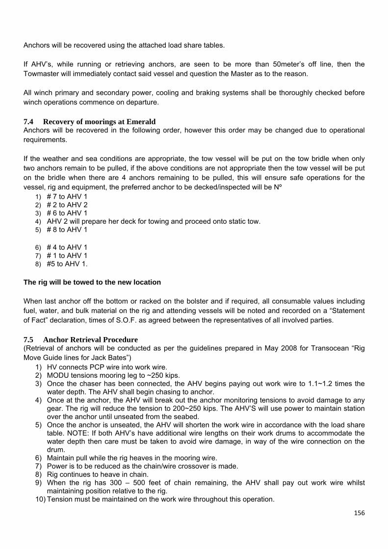
156
Anchors will be recovered using the attached load share tables. If AHV’s, while running or retrieving anchors, are seen to be more than 50meter’s off line, then the Towmaster will immediately contact said vessel and question the Master as to the reason. All winch primary and secondary power, cooling and braking systems shall be thoroughly checked before winch operations commence on departure. 7.4 Recovery of moorings at Emerald Anchors will be recovered in the following order, however this order may be changed due to operational requirements. If the weather and sea conditions are appropriate, the tow vessel will be put on the tow bridle when only two anchors remain to be pulled, if the above conditions are not appropriate then the tow vessel will be put on the bridle when there are 4 anchors remaining to be pulled, this will ensure safe operations for the vessel, rig and equipment, the preferred anchor to be decked/inspected will be Nº
1) # 7 to AHV 1 2) # 2 to AHV 2 3) # 6 to AHV 1 4) AHV 2 will prepare her deck for towing and proceed onto static tow. 5) # 8 to AHV 1
6) # 4 to AHV 1 7) # 1 to AHV 1 8) #5 to AHV 1.
The rig will be towed to the new location When last anchor off the bottom or racked on the bolster and if required, all consumable values including fuel, water, and bulk material on the rig and attending vessels will be noted and recorded on a “Statement of Fact” declaration, times of S.O.F. as agreed between the representatives of all involved parties. 7.5 Anchor Retrieval Procedure (Retrieval of anchors will be conducted as per the guidelines prepared in May 2008 for Transocean “Rig Move Guide lines for Jack Bates”)
1) HV connects PCP wire into work wire. 2) MODU tensions mooring leg to ~250 kips. 3) Once the chaser has been connected, the AHV begins paying out work wire to 1.1~1.2 times the
water depth. The AHV shall begin chasing to anchor. 4) Once at the anchor, the AHV will break out the anchor monitoring tensions to avoid damage to any
gear. The rig will reduce the tension to 200~250 kips. The AHV’S will use power to maintain station over the anchor until unseated from the seabed.
5) Once the anchor is unseated, the AHV will shorten the work wire in accordance with the load share table. NOTE: If both AHV’s have additional wire lengths on their work drums to accommodate the water depth then care must be taken to avoid wire damage, in way of the wire connection on the drum.
6) Maintain pull while the rig heaves in the mooring wire. 7) Power is to be reduced as the chain/wire crossover is made. 8) Rig continues to heave in chain. 9) When the rig has 300 – 500 feet of chain remaining, the AHV shall pay out work wire whilst
maintaining position relative to the rig. 10) Tension must be maintained on the work wire throughout this operation.

157
11) When the chasing collar and anchor shackle is at the bolster the AHV shall pay out wire and/or reduce power to allow the anchor to rest below the bolster.
12) Once rig has secured the anchor on the bolster the AHV shall disconnect the PCP and pass it back to the rig.
13) After the PCP is disconnected and prior to the crane hook being secured to the PCP, the PCP shall be confirmed as being under no abnormal loading or other wise fouled. Only on the advice and confirmation of a slack PCP between the vessel deck and the crane operator will the PCP weight be released to the rig crane.
14) During the heaving in process the rig winch operator will inform the vessel at each 1000ft interval. NOTE – To avoid adverse or shock loading to the rig crane, it is imperative that the PCP is confirmed not to be under abnormal tension or otherwise fouled prior to the weight being transferred to the Rig Crane. The PCP is to be lowered over the stern roller, using the AHV tugger winch’s, before the crane takes the weight . The PCP is only to be released (tripped) on the advice of the crane operator. 7.6 Connecting Main Tow Procedure
1) AHV comes astern between the pontoons forward and holds position. 2) Rig crew will lower the forerunner to allow the AHV crew to grapple the heaving sling, once grappled
the rig crew will continue to pay out tugger wire to supervisor instructions. 3) Heaving sling will be attached to the AHV tugger, hauled on board and forerunner socket will be
locked in Jaws/Kalm Forks. 4) AHV tow wire will be connected, Jaws/Kalm Forks lowered and AHV tow wire payed out to 200m for
static tow. 8.0 Procedure for checking anchor for damage There are two areas on the anchor that should be checked for damage:
I. Top section of the shank (near the main anchor shackle) and stiffener plates. The shank should be checked to confirm if it is still straight, i.e. the shackle is still inline with the centreline of the fluke. The stiffeners should be checked to confirm they are still parallel and that no cracking has occurred at the connection with the main shank plates.
II. Winglets on the fluke tips. These should be checked for any damage due to bending.
Required information for damage assessment: To determine the extent of any noted damage i.e. where it is and how much and the type of damage, the following information will be required:
I. Photographs of the damaged anchor including details of damage and overview photos.
II. A filled out damage form of the anchor (enclosed drawing 6021-01. On this drawing the extent of any damage can be indicated as well as anchor serial number(s).
III. With both photographs and the damage report form it will be easier to evaluate the extent of the
damage and whether the anchor is repairable. PLEASE USE THE INSPECTION FORM ON THE LAST PAGE OF THIS PROCEDURE TO REPORT CONDITION OF EACH ANCHOR. PLEASE RETURN COMPLETED FORMS TO THE RIG UPON COMPLETION OF ANCHOR HANDLING OPERATIONS.
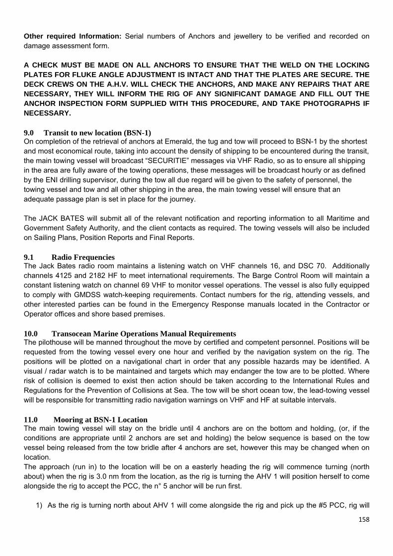
158
Other required Information: Serial numbers of Anchors and jewellery to be verified and recorded on damage assessment form. A CHECK MUST BE MADE ON ALL ANCHORS TO ENSURE THAT THE WELD ON THE LOCKING PLATES FOR FLUKE ANGLE ADJUSTMENT IS INTACT AND THAT THE PLATES ARE SECURE. THE DECK CREWS ON THE A.H.V. WILL CHECK THE ANCHORS, AND MAKE ANY REPAIRS THAT ARE NECESSARY, THEY WILL INFORM THE RIG OF ANY SIGNIFICANT DAMAGE AND FILL OUT THE ANCHOR INSPECTION FORM SUPPLIED WITH THIS PROCEDURE, AND TAKE PHOTOGRAPHS IF NECESSARY. 9.0 Transit to new location (BSN-1) On completion of the retrieval of anchors at Emerald, the tug and tow will proceed to BSN-1 by the shortest and most economical route, taking into account the density of shipping to be encountered during the transit, the main towing vessel will broadcast “SECURITIE” messages via VHF Radio, so as to ensure all shipping in the area are fully aware of the towing operations, these messages will be broadcast hourly or as defined by the ENI drilling supervisor, during the tow all due regard will be given to the safety of personnel, the towing vessel and tow and all other shipping in the area, the main towing vessel will ensure that an adequate passage plan is set in place for the journey. The JACK BATES will submit all of the relevant notification and reporting information to all Maritime and Government Safety Authority, and the client contacts as required. The towing vessels will also be included on Sailing Plans, Position Reports and Final Reports. 9.1 Radio Frequencies The Jack Bates radio room maintains a listening watch on VHF channels 16, and DSC 70. Additionally channels 4125 and 2182 HF to meet international requirements. The Barge Control Room will maintain a constant listening watch on channel 69 VHF to monitor vessel operations. The vessel is also fully equipped to comply with GMDSS watch-keeping requirements. Contact numbers for the rig, attending vessels, and other interested parties can be found in the Emergency Response manuals located in the Contractor or Operator offices and shore based premises. 10.0 Transocean Marine Operations Manual Requirements The pilothouse will be manned throughout the move by certified and competent personnel. Positions will be requested from the towing vessel every one hour and verified by the navigation system on the rig. The positions will be plotted on a navigational chart in order that any possible hazards may be identified. A visual / radar watch is to be maintained and targets which may endanger the tow are to be plotted. Where risk of collision is deemed to exist then action should be taken according to the International Rules and Regulations for the Prevention of Collisions at Sea. The tow will be short ocean tow, the lead-towing vessel will be responsible for transmitting radio navigation warnings on VHF and HF at suitable intervals. 11.0 Mooring at BSN-1 Location The main towing vessel will stay on the bridle until 4 anchors are on the bottom and holding, (or, if the conditions are appropriate until 2 anchors are set and holding) the below sequence is based on the tow vessel being released from the tow bridle after 4 anchors are set, however this may be changed when on location. The approach (run in) to the location will be on a easterly heading the rig will commence turning (north about) when the rig is 3.0 nm from the location, as the rig is turning the AHV 1 will position herself to come alongside the rig to accept the PCC, the n° 5 anchor will be run first.
1) As the rig is turning north about AHV 1 will come alongside the rig and pick up the #5 PCC, rig will

159
pay out to the crossover. 2) Rig will pay out chain and wire until the #5 anchor is run to the drop position, the rig and AHV
following the load share table as described in the Marine Operations Manual. 3) On instruction from the rig the # 5 anchor will be put on the sea bed. 4) # 1 to AHV 1 5) # 4 to AHV 1 6) # 8 to AHV 1 7) AHV 2 will come off the bridle and prepare her deck for anchor handling operations 8) # 6 to AHV 2 9) # 2 to AHV 1 10) # 7 to AHV 2 11) # 3 to AHV 1
11.1 Anchor Deployment Procedure
1) AHV moves in and picks up the PCP 2) When PCP is connected to AHV work wire, AHV will pay out work wire and PCP to required length
to take the anchor off the bolster, AHV will then move into position adjacent to the anchor on the bolster.
3) Rig winch will liase with AHV and when ready will pay out anchor chain, sufficient to allow the anchor to come clear of the bolster, AHV will maintain sufficient tension on the PCP to assist in pulling the anchor from the bolster, if required, (usually about 10 to 15 T) when anchor is clear of the bolster and about 200ft of rig chain is paid out, AHV will bring the anchor to it’s roller and check orientation is correct.
4) If orientation is correct anchor will be put back below the stern roller, AHV will maintain tension while paying out wire (as per load share table) and proceed out to the cross over, rig winch will pay out chain to crossover (3043ft), if at stage 4 the orientation of the anchor is incorrect, the AHV will re-orientate by allowing the anchor to slip through the collar and heaving it back up into the collar.
5) When crossover is made both rig winch and AHV will pay out wire (as per load share table) AHV will adjust power to maintain tension keeping the wire off the bolster and also to carry her share of the load, the AHV will keep as close to the surveyed anchor run line as possible.
6) Adhering to the attached load share table (wire pay out) the anchor will be carried out to the drop point, AHV will apply power to maintain tension, as required.
7) Once at the drop point AHV will apply power to stretch out the system and will then be informed by the rig when to place the anchor on the bottom.
8) Once the anchor is on the bottom and is said to be holding tension the AHV will strip back to the rig and hand back the PCP, as per instructions and in a controlled manner, as per Note at bottom of section 6.2.
9) Whilst deploying chain and wire the rig winch will inform the AHV at every 1000ft paid out. 12.0 Anchor Pre-Tensioning When anchor deployment is completed the anchors should be pre-tensioned to ensure adequate holding. Anchors will be pre-tensioned in the following opposite pairs: Pre-tension should be to 360 KIPS
1) No. 1 and No. 5 2) No. 4 and No. 8 3) No. 6 and No 2 4) No. 3 and No. 7
During anchor pre-tensioning, winch tensions will be checked against motor amps. When all anchors have been successfully pre-tensioned, the tensions will be adjusted for working at the Warrior location. Working Tension should be 300~350 KIPS 12.1 Anchor Slippage
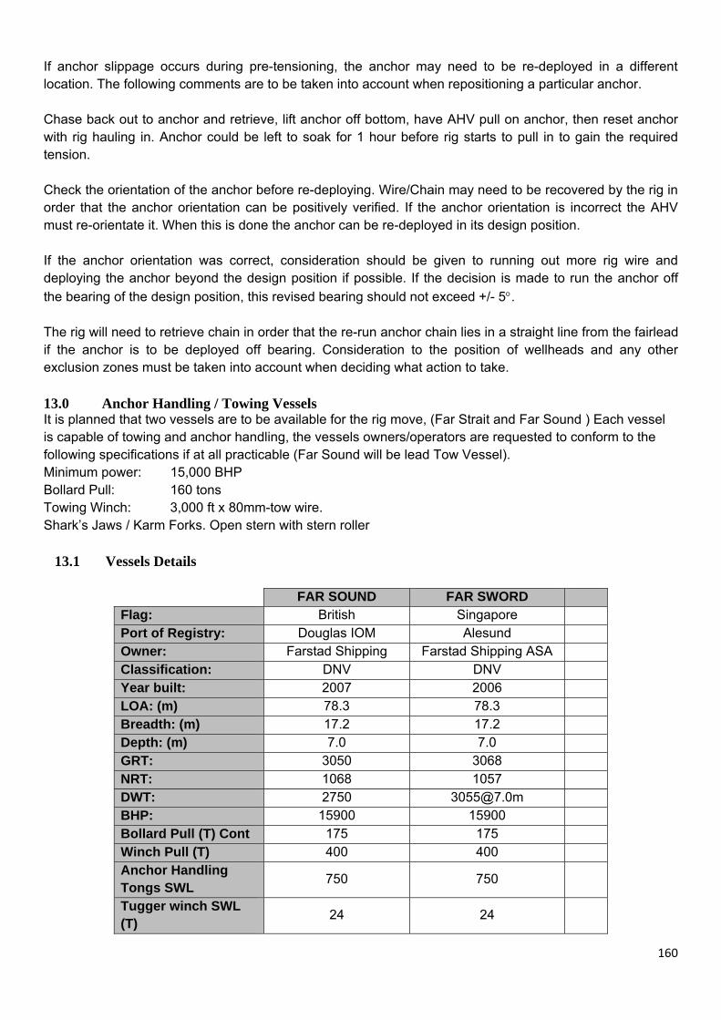
160
If anchor slippage occurs during pre-tensioning, the anchor may need to be re-deployed in a different location. The following comments are to be taken into account when repositioning a particular anchor. Chase back out to anchor and retrieve, lift anchor off bottom, have AHV pull on anchor, then reset anchor with rig hauling in. Anchor could be left to soak for 1 hour before rig starts to pull in to gain the required tension. Check the orientation of the anchor before re-deploying. Wire/Chain may need to be recovered by the rig in order that the anchor orientation can be positively verified. If the anchor orientation is incorrect the AHV must re-orientate it. When this is done the anchor can be re-deployed in its design position. If the anchor orientation was correct, consideration should be given to running out more rig wire and deploying the anchor beyond the design position if possible. If the decision is made to run the anchor off the bearing of the design position, this revised bearing should not exceed +/- 5°. The rig will need to retrieve chain in order that the re-run anchor chain lies in a straight line from the fairlead if the anchor is to be deployed off bearing. Consideration to the position of wellheads and any other exclusion zones must be taken into account when deciding what action to take. 13.0 Anchor Handling / Towing Vessels It is planned that two vessels are to be available for the rig move, (Far Strait and Far Sound ) Each vessel is capable of towing and anchor handling, the vessels owners/operators are requested to conform to the following specifications if at all practicable (Far Sound will be lead Tow Vessel). Minimum power: 15,000 BHP Bollard Pull: 160 tons Towing Winch: 3,000 ft x 80mm-tow wire. Shark’s Jaws / Karm Forks. Open stern with stern roller 13.1 Vessels Details
FAR SOUND FAR SWORD Flag: British Singapore Port of Registry: Douglas IOM Alesund Owner: Farstad Shipping Farstad Shipping ASA Classification: DNV DNV Year built: 2007 2006 LOA: (m) 78.3 78.3 Breadth: (m) 17.2 17.2 Depth: (m) 7.0 7.0 GRT: 3050 3068 NRT: 1068 1057 DWT: 2750 [email protected] BHP: 15900 15900 Bollard Pull (T) Cont 175 175 Winch Pull (T) 400 400 Anchor Handling Tongs SWL 750 750
Tugger winch SWL (T) 24 24

161
Towing Pins SWL (T) 300 300 Roller SWL (T) 550 550 Length of work wire 1x2000m 80mm 1x2200m 80mm Storage drum 1x1100,80mm None
14.0 Mooring System Anchors 8 x 15 tonne Bruce FFTS Mk.4 x 5 anchors Mk 3 x 3 anchors Chain 8 x 43 feet 4 ½ inch chain 8 x 3000 feet 3-9/16 inch chain Wire 8 wires at 3 ¾ inch lengths complete N.B. All wires are now good new anchor fitted to # 3 fluke ankles at
medium.
Winch Length of wire (feet) Additional Comments (eg damage, short, etc)
1 10,000 Wire renewed 04-11-08 2 10,000 Nil 3 10,000 Gypsy renewed 04-11-08 4 10,000 Nil 5 10,000 Nil 6 10,000 Nil 7 10,000 N° 7 anchor is on the deck of the Far Sound 8 10,000 Wire renewed 04-10-08
If required, fluke angles will be reset using the approved Bruce method.
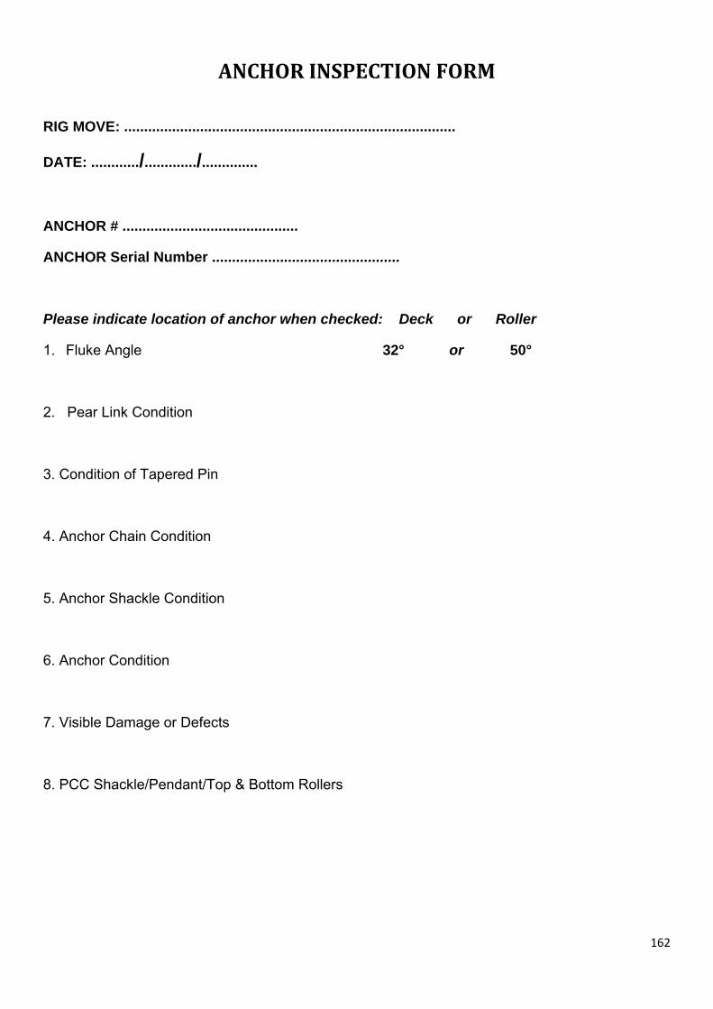
162
ANCHOR INSPECTION FORM
RIG MOVE: ...................................................................................
DATE: ............/............./..............
ANCHOR # ............................................
ANCHOR Serial Number ...............................................
Please indicate location of anchor when checked: Deck or Roller
1. Fluke Angle 32° or 50°
2. Pear Link Condition
3. Condition of Tapered Pin
4. Anchor Chain Condition
5. Anchor Shackle Condition
6. Anchor Condition
7. Visible Damage or Defects
8. PCC Shackle/Pendant/Top & Bottom Rollers

163
SPARE EQUIPMENT LIST
JACK BATES Onboard Anchor Spare Equipment List
0 J-hook Locking
1 J-hook Regular
0 Grapnel
2 PCP
2 Collar
3 Kenter links
2 Pear Links
Far Strait Onboard Equipment List
0 J-hook Locking
1 J-hook Regular
0 Grapnel
0 PCC
0 Horse collar - removable
0 Kenter links
0 Pear Links
Far Sound Onboard Equipment List
0 J-hook Locking
0 J-hook Regular
0 Grapnel
0 PCC
0 Horse collar - removable
0 Kenter links

164
RIG MOVE MEETING PERSONNEL ATTENDANCE RECORD
RIG MOVE: ...................................................................................
DATE: ............/............./..............
Position
Name Signature
Transocean OIM
Transocean Barge Supervisor
Transocean Assistant BS
Transocean BCO
Transocean BCO
Transocean RSTC
Transocean Toolpusher
Transocean Towmaster
ENI Company Rep
ENI Surveyor
ENI Logistics
Vessel master
Vessel master
Surveyor
Surveyor
ROV Supervisor
ROV Supervisor

165
PRE RIG MOVE CHECK LIST (to be included in Pre Move Meeting Minutes)
Positions From To Latitude 05°47’47.215”N
Longitude 096°42’33.271E Block Location Name Emerald BSN-1
Water Depth 1256m 840m
Operator
ENI Indonesia
Checks to be Completed Checked
1 Conduct pre move meeting with all concerned parties aboard the MODU. Ensure all potential hazards have been identified and relevant precautions stated in the move procedures have been discussed.
2
Confirm vessel Masters attend the meeting. If weather or operational conditions prevent their attendance, confirm vessel Masters have been instructed via VHF of the procedures. Ensure all potential hazards have been identified and relevant precautions stated in the move procedures have been discussed.
3 Confirm with the QA/QC surveyor all navigational units are operational. QA/QC surveyor to complete test of each unit in respect to remote access to AHTS navigation systems if applicable.
4 Confirm all navigation systems have the same version.
5 Ensure that an adequate towing vessel package has been provided and that all tow gear is in satisfactory condition.
6 Confirm all bathymetric charts are on board the MODU. Confirm AHTs have copies of bathymetric charts.
7 Confirm all parties have the latest revision of the Rig Move Procedure. Note: RMP Rev……..
8 Check with AHT Masters the work wire and tow wire status. Confirm total hours on each AHT tow wire.
9 AHT Masters to report vessel operational status. Any deficiencies are to be noted in the pre-move meeting minutes.
10 Ensure all nautical charts for the intended route are on board the lead tow vessel and the MODU.
11 Confirm the weather forecast is suitable for rig move operations.
12 Confirm MODU has crew available for the inspection of the crossover on recovery of the anchors
13 Confirm the number of approved winch operators available.
14 Confirm anchors to be inspected during the move Anchor #......7......... Anchor #.......................
15 Confirm MODU specific pre move checklist is complete. 16 Confirm AHT crew change status. 17 Confirm deck inspection of all sea fastenings.

166
PROCEDURAL DOCUMENT CHANGE ACCEPTANCE SHEET
Log of Deviation/Change Approval Date:
Intended deviation:
Deviation/Change Approved by Transocean OIM:
Name: Signature:
Deviation/Change Approved by Transocean Tow Master:
Name: Signature:
Deviation/Change Approved by Drilling Supervisor ENI
Name: Signature:

167
Tow Vessel Responsibility
I, ……….., O.I.M. of the MODU Jack Bates, officially hand over responsibility of the tow of the Jack Bates to the Master of the Far Sword, from this point in time until arrival at the BSN-1 Location said Master will have responsibility for the safe conduct of the tow.
In making his decisions, in regards to the safe conduct of the tow, the Master of the Far Sword will consult with and include the Jack Bates O.I.M and the Jack Bates TowMaster in any decision making process.
Name………………………Signature…………………………..OIM, Jack Bates.
Acceptance of Responsibility.
Name………………Signature……………………Master, Far Sound/Far Sword.