Capitolo 3.7 2015 Layout 1
8
3.7.2 DESCRIPTION The EPE bladder is made by two different and separable parts. One is the rubber bladder of which the main feature lies in an original and well developed process that allows the construction in a single piece. The second part is the gas valve assembly that is seal connected on the bladder mechanically. This unique method allows to seal connect on the same bladder different types. 3.7.3 SPECIAL GAS VALVE: NON EPOLL ACCUMULATORS EPE bladders, in addition to their use in EPE accumulators, are perfectly interchangeable with many others brands available in the market. In order to do that, gas valves (see below) are available with nonstandard stem diameters (ØB) and charge-connections. EPE ITALIANA s.r.l. - Viale Spagna,112 • 20093 Cologno Monzese (Mi) Italy Tel.: +39 02 25459028 • Fax: +39 02 25 25459773 • E-mail: [email protected] • Internet: www.epeitaliana.it 1 3.7.1 TECHNICAL DATA THE BLADDER, used in the standard version of the accumulators of all the series offered by EPE, is made in butadiene-acrilnitrile rubber (NBR) with medium-high ACN content which we have denoted “standard nitrile” and distinguished with the letter P. The “P” bladder is above all suitable for use with mineral oils but gives also excellent results with many other liquids. The operating temperature range is between –20 and +80°C. For special requirements, temperatures exceeding the above limits, special liquids, etc. the bladder can be supplied in the following materials: Nitrile for low temperatures (F), Nitrile for hydrocarbons (H), Hydrogenated Ni- trile (K), Butyl (B), Ethylene-propylene (E), Neoprene (N), Epichlorohydrin (Y), Viton (V). See section 1,5. N.B. Not all the sizes of bladders are available in all the materials. Please consult our Technical Service Department before ordering. of gas valve assembly. The two parts, bladder and gas valve assembly, can be ordered separa- tely so when is necessary the replacement of the bladder, it is possible to use again the gas valve assembly saving in this way money on the purchasing price of the spare baldder. THE GAS VALVE used in the EPE accumulators is made of phosphated carbon steel, in the following three versions: S = STANDARD. For capacities from 0,2 to 55 litres with inflating valve 5/8” UNF. This valve can be supplied with Ø B and special inflation connec- tions. ST = TRANSFER. Suitable for use with the accumulator connected to one or more additional nitrogen bottles. For capacities from 5 to 55 litres. SL = LIQUID SEPARATOR. It is used when a liquid is also inside the bladder. For capacities from 0,2 to 55 litres. UPON REQUEST, all the valves can be supplied with chemical nickel coating 25 µm or 40 µm. (other thickness to be specified) or in stainless steel. SPARE BLADDERS AND VALVES type S E 09-14 3.7 3.7a
Transcript of Capitolo 3.7 2015 Layout 1

3.7.2 DESCRIPTIONThe EPE bladder is made by two different and separable parts.One is the rubber bladder of which the main feature lies in an originaland well developed process that allows the construction in a single piece.The second part is the gas valve assembly that is seal connected on thebladder mechanically. This unique method allows to seal connect on thesame bladder different types.
3.7.3 SPECIAL GAS VALVE: NON EPOLL ACCUMULATORS
EPE bladders, in addition to their use in EPE accumulators, are perfectlyinterchangeable with many others brands available in the market.In order to do that, gas valves (see below) are available with nonstandardstem diameters (ØB) and charge-connections.
EPE ITALIANA s.r.l. - Viale Spagna,112 • 20093 Cologno Monzese (Mi) Italy
Tel.: +39 02 25459028 • Fax: +39 02 25 25459773 • E-mail: [email protected] • Internet: www.epeitaliana.it 1
3.7.1 TECHNICAL DATATHE BLADDER, used in the standard version of the accumulators of allthe series offered by EPE, is made in butadiene-acrilnitrile rubber (NBR)with medium-high ACN content which we have denoted “standard nitrile”and distinguished with the letter P. The “P” bladder is above all suitablefor use with mineral oils but gives also excellent results with many otherliquids. The operating temperature range is between –20 and +80°C. Forspecial requirements, temperatures exceeding the above limits, specialliquids, etc. the bladder can be supplied in the following materials: Nitrilefor low temperatures (F), Nitrile for hydrocarbons (H), Hydrogenated Ni-trile (K), Butyl (B), Ethylene-propylene (E), Neoprene (N), Epichlorohydrin(Y), Viton (V). See section 1,5.N.B. Not all the sizes of bladders are available in all the materials.Please consult our Technical Service Department before ordering.of gas valve assembly.The two parts, bladder and gas valve assembly, can be ordered separa-tely so when is necessary the replacement of the bladder, it is possibleto use again the gas valve assembly saving in this way money on thepurchasing price of the spare baldder.
THE GAS VALVE used in the EPE accumulators is made of phosphatedcarbon steel, in the following three versions:
S = STANDARD. For capacities from 0,2 to 55 litres with inflating valve5/8” UNF.This valve can be supplied with Ø B and special inflation connec-tions.
ST = TRANSFER. Suitable for use with the accumulator connected toone or more additional nitrogen bottles. For capacities from 5 to 55litres.
SL = LIQUID SEPARATOR. It is used when a liquid is also inside thebladder. For capacities from 0,2 to 55 litres.
UPON REQUEST, all the valves can be supplied with chemical nickelcoating 25 µm or 40 µm. (other thickness to be specified) or in stainlesssteel.
SPARE BLADDERS AND VALVES type S E 09-143.7
3.7a
Capitolo 3.7 2015_Layout 1 25/03/15 13:47 Pagina 1

EPE ITALIANA s.r.l. - Viale Spagna,112 • 20093 Cologno Monzese (Mi) Italy
Tel.: +39 02 25459028 • Fax: +39 02 25 25459773 • E-mail: [email protected] • Internet: www.epeitaliana.it 2
SPARE BLADDERS AND VALVES type SE 09-143.7
Codeletter Polymer ISO
Temperaturerange (°C) Some of the liquids compatible with the polymer
P Standard nitrile (Perburan) NBR -20 ÷ +80 Aliphatic hydrocarbons (propane, butane, gasoline, oils, mineral grea-ses, diesel fuel, fuel oil, kerosene), mineral greases and oils, HFA -HFB - HFC fluids, many dilute acids, alkalis, saline solutions, water,water glycol.
F Low temperature nitrile NBR -40 ÷ +70 The same as with standard nitrile + a number of different types ofFreon. (This contains less acrylonitrile than the standard and is there-fore more suitable for low temperatures, but its chemical resistance isslightly lower).
H Nitrile for hydrocarbons NBR -10 ÷ +90Regular and premium grade slightly aromatic gasoline (and all the li-quids for standard nitrile).
K Hydrogenated nitrile HNBR -30 ÷ +130 The same as with standard nitrile but with excellent performance athigh and low temperatures.
B Butyl IIR -30 ÷ +100 Hot water up to 100°C, glycol-based brake fluids, many acids andbases, salt solutions, polar solvents such as alcohols, ketones andesters, polyglycol-based hydraulic fluids (HFC fluids) and bases ofesters of phosphoric acid (HFD-R fluids), silicone oils and greases,Skydrol 500 and 7000, resistance to ozone, aging and weathering.
E Ethylene-Propylene EPDM -30 ÷ +100 Hot water up to 100°C, glycol-based brake fluids, many organic andinorganic acids, detergents, solutions of sodium and potassium, pho-sphate ester-based hydraulic fluids, (HFD-R), silicone oils and greases,many polar solvents (alcohol, ketones, esters), Skydrol 500 and 7000,resistance to ozone, aging and weathering.
N Chloroprene (Neoprene) CR -30 ÷ +100 Mineral oils of paraffin, silicone oils and greases, water and aqueoussolutions, refrigerants (ammonia, carbon dioxide, Freon), naphthenicmineral oils, low molecular aliphatic hydrocarbons (propane, butane,fuel), brake fluids based on glycol, better resistance to ozone, weathe-ring and aging compared to NBR rubber.
Y Epichloridrin ECO -30 ÷ +110 Mineral oils and greases, aliphatic hydrocarbons (propane, butane andgasoline), silicone oils and greases, water at room temperature, resi-stance to ozone, aging and weathering.
V Fluorocarbon FKM -10 ÷ +150 Mineral oils and greases, non-flammable fluids of HFD group, silicone oilsand greases, animal and vegetable oils and greases, aliphatic hydrocar-bons (gasoline, butane, propane, natural gas), aromatics hydrocarbons(benzene, toluene), chlorinated hydrocarbons (Tetrachloroethylene, car-bon tetrachloride), fuel (regular, super and containing methanol), excellentresistance to ozone, weathering and aging.
For other hydraulic fluid and/or temperatures, please consult us.
3.7.4 BLADDER-TEMPERATURE-LIQUID COMPATIBILITYWhen selecting the accumulator variant, pay attention to the following non-binding notes with regard to hydraulic fluid, bladder material and the per-missive temperature range. (see Section 1.5)
3.1c
Capitolo 3.7 2015_Layout 1 25/03/15 13:48 Pagina 2
EPE ITALIANA s.r.l. - Viale Spagna,112 • 20093 Cologno Monzese (Mi) Italy
Tel.: +39 02 25459028 • Fax: +39 02 25 25459773 • E-mail: [email protected] • Internet: www.epeitaliana.it 3
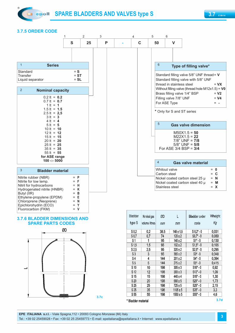
3.7.5 ORDER CODE
S 25 P - C 50 V
Series
Standard = STransfer = STLiquid separator = SL
Bladder material
Nitrile rubber (NBR) = PNitrile for low temp. = FNitril for hydrocarbons = HHydrogenated nitrile (HNBR) = KButyl (IIR) = BEthylene-propylene (EPDM) = EChloroprene (Neoprene) = NEpichlorohydrin (ECO) = YFluorocarbon (FKM) = V
Nominal capacity
0.2 lt = 0.20.7 lt = 0.7
1 lt = 11.5 lt = 1.52.5 lt = 2,5
3 lt = 34 lt = 45 lt = 5
10 lt = 1012 lt = 1215 lt = 1520 lt = 2025 lt = 2535 lt = 3555 lt = 55
for ASE range100 -:- 5000
Type of filling valve*
Standard filling valve 5/8” UNF thread= V
Standard filling valve with 5/8” UNF
thread in stainless steel = VX
Without filling valve (thread hole M12x1.5) = V0
Brass filling valve 1/4” BSP = V2
Filling valve 7/8” UNF = V4
For ASE Type = -
Gas valve material
Whitout valve = 0
Carbon steel = C
Nickel coated carbon steel 25 µ = N
Nickel coated carbon steel 40 µ = M
Stainless steel = X
Gas valve dimension
M50X1.5 = 50M22X1.5 = 227/8” UNF = 7/85/8” UNF = 5/8
For ASE 3/4 BSP = 3/4
SPARE BLADDERS AND VALVES type S E 09-143.7
1 2 3 4 5 6
1
2
3
6
5
4
3.7.6 BLADDER DIMENSIONS AND SPARE PARTS CODES
3.7c3.7d
* Only for S and ST series
Capitolo 3.7 2015_Layout 1 25/03/15 13:48 Pagina 3

EPE ITALIANA s.r.l. - Viale Spagna,112 • 20093 Cologno Monzese (Mi) Italy
Tel.: +39 02 25459028 • Fax: +39 02 25 25459773 • E-mail: [email protected] • Internet: www.epeitaliana.it 4
SPARE BLADDERS AND VALVES type SE 09-143.7
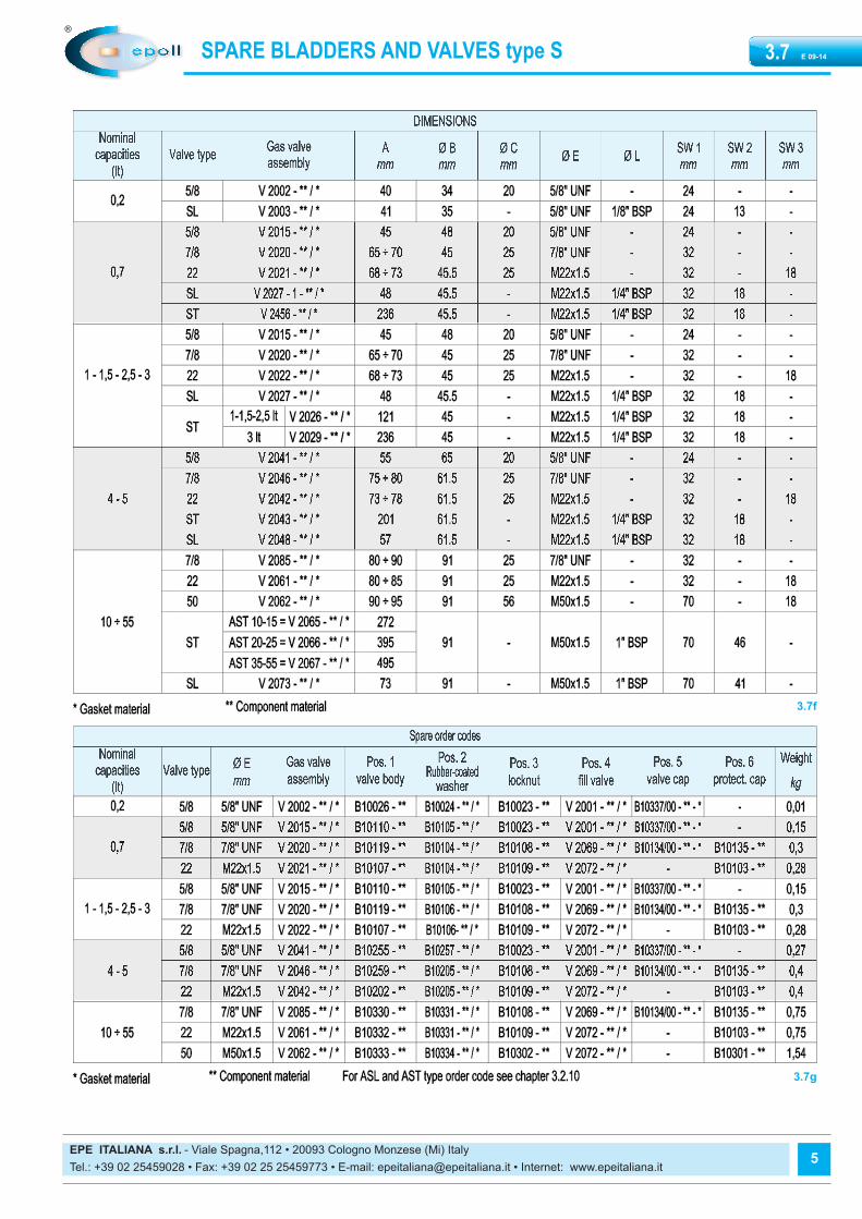
3.7.7 VALVE DIMENSIONS AND SPARE PARTS CODE
3.7e
Capitolo 3.7 2015_Layout 1 25/03/15 13:48 Pagina 4
EPE ITALIANA s.r.l. - Viale Spagna,112 • 20093 Cologno Monzese (Mi) Italy
Tel.: +39 02 25459028 • Fax: +39 02 25 25459773 • E-mail: [email protected] • Internet: www.epeitaliana.it 5
SPARE BLADDERS AND VALVES type S E 09-143.7
3.7f
3.7g
Capitolo 3.7 2015_Layout 1 25/03/15 13:48 Pagina 5
EPE ITALIANA s.r.l. - Viale Spagna,112 • 20093 Cologno Monzese (Mi) Italy
Tel.: +39 02 25459028 • Fax: +39 02 25 25459773 • E-mail: [email protected] • Internet: www.epeitaliana.it 6
SPARE BLADDERS AND VALVES type SE 09-143.7
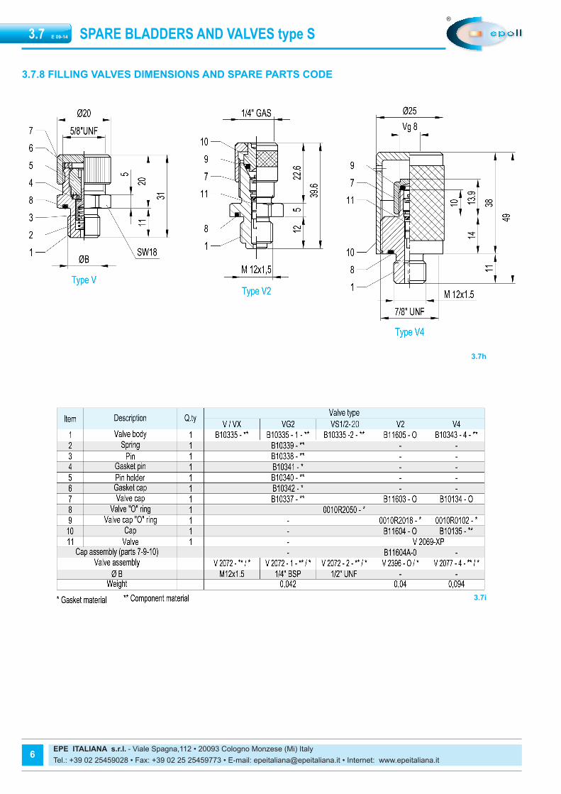
3.7.8 FILLING VALVES DIMENSIONS AND SPARE PARTS CODE
3.7h
3.7i
Capitolo 3.7 2015_Layout 1 25/03/15 13:48 Pagina 6

EPE ITALIANA s.r.l. - Viale Spagna,112 • 20093 Cologno Monzese (Mi) Italy
Tel.: +39 02 25459028 • Fax: +39 02 25 25459773 • E-mail: [email protected] • Internet: www.epeitaliana.it
3.7.9 MAINTENANCE
HandlingThe original packaging is suitable for handling and storage. Where ne-cessary, you should use suitable lifting equipment to support the weightof the accumulators.However protect from impact the packaging and handle it with care.
StorageDuring storage in the warehouse, leave the product in its original packaging, keeping it away from heat sources and naked flames. The storagetemperature should be between +10 and +40°C. The maximum time ofstorage is two years. After time is no longer usable.
Disassembly bladder from gas valve- First time remove the assembly bladder plus gas valve from accumu-
lator shell
3.7l
- Remove the rubber-coated washer, if is necessary usea small tool for to leverage.
3.7m
- Remove the rubber-coated washer, and slip-off
- Remove the rubber-coated washer. 3.7n
- Remove the gas valve, tilting slightly 3.7o
- Remove the gas valve,by pulling the bladder. 3.7p
- Remove the gas valve,by pulling the bladder whit hand 3.7p
7
SPARE BLADDERS AND VALVES type S E 09-143.7
Capitolo 3.7 2015_Layout 1 25/03/15 13:48 Pagina 7

EPE ITALIANA s.r.l. - Viale Spagna,112 • 20093 Cologno Monzese (Mi) Italy
Tel.: +39 02 25459028 • Fax: +39 02 25 25459773 • E-mail: [email protected] • Internet: www.epeitaliana.it
Assembly the new bladder with the gas valve
3.7r
- Put the gas body valve on the mouth of bladder an push.
3.7s
- Position the body gas valve.
3.7t
- Insert the rubber-coated washer.
3.7u
- Slip-on the rubber-coated washer.
3.7v
- Press the body gas valve and the rubber-coated washer forwardthe bladder .
3.7z
- Body gas valve correctly assembled.
Reproduction is forbidden.
In the spirit of continuous improvement, our products may be changed.
8
SPARE BLADDERS AND VALVES type SE 09-143.7
Capitolo 3.7 2015_Layout 1 25/03/15 13:48 Pagina 8