Capacitive Touch Thermostat User Interface With … user setting Included in TI Design haptics TI...
29
LED Relay driver Temperature sensor Wi-Fi radio Humidity sensor MPU Sub 1-GHz or 2.4-GHz radio Load switch Voltage supervisor IR temp sensor Load switch Backlight LCD screen LCD driver Ambient light sensor LCD backlight controller Light MSP430 Captivate MCU FRAM saving user setting haptics Included in TI Design TI Designs Capacitive Touch Thermostat User Interface With CapTIvate ™ Technology TI Designs Design Features TI Designs provide the foundation that you need • MSP430™ CapTIvate™ MCU for Capacitive Touch including methodology, testing and design files to Sensing quickly evaluate and customize the system. TI Designs • CapTIvate Design Center Support Enabling Real- help you accelerate your time to market. Time Customization of Response Time, Sensitivity, and Other Parameters from a Host PC Design Resources • Multiple Modes of Operation, Including a Battery- Powered Mode for Increased Battery Life and a TIDM-CAPTIVATE- Tool Folder Containing Design Files THERMOSTAT-UI Line-Powered Mode for Increased Noise Immunity MSP430FR2633 Product Folder • Less Than 50 μA Average Current in Battery- TIDM-FRAM-THERMOSTAT Design Folder Powered Mode, Allowing for 2 Years of Battery Life CapTIvate Design Center Tool Folder on AAA Batteries • Conducted Noise Immunity at the Commercial Product Level (IEC 61000-4-6 Class A at 3 Vrms) ASK Our E2E Experts in Line-Powered Mode WEBENCH® Calculator Tools • Mutual Capacitance Technology Enables 8 Buttons With Only 6 MCU Pins • Maintained State and Momentary Capacitive Switch Implementations • Ferroelectric Random Access Memory (FRAM) Enables Button State and Configuration Retention Through Power Loss Featured Applications • Capacitive Touch Thermostat User Interface An IMPORTANT NOTICE at the end of this TI reference design addresses authorized use, intellectual property matters and other important disclaimers and information. MSP430, CapTIvate are trademarks of Texas Instruments. All other trademarks are the property of their respective owners. 1 TIDUAV1 – November 2015 Capacitive Touch Thermostat User Interface With CapTIvate ™ Technology Submit Documentation Feedback Copyright © 2015, Texas Instruments Incorporated
Transcript of Capacitive Touch Thermostat User Interface With … user setting Included in TI Design haptics TI...

LED
Relay driver
Temperature sensor Wi-Fi radio
Humidity sensor
MPU
Sub 1-GHz or 2.4-GHz radio
Load switch
Voltage supervisor
IR temp sensor
Load switch
Backlight
LCD screenLCD
driver
Ambient light sensor
LCD backlightcontroller
Light
MSP430
CaptivateMCU
FRAM saving user setting
hapticsIncluded in TI Design
TI DesignsCapacitive Touch Thermostat User Interface WithCapTIvate™ Technology
TI Designs Design FeaturesTI Designs provide the foundation that you need • MSP430™ CapTIvate™ MCU for Capacitive Touchincluding methodology, testing and design files to Sensingquickly evaluate and customize the system. TI Designs • CapTIvate Design Center Support Enabling Real-help you accelerate your time to market. Time Customization of Response Time, Sensitivity,
and Other Parameters from a Host PCDesign Resources• Multiple Modes of Operation, Including a Battery-
Powered Mode for Increased Battery Life and aTIDM-CAPTIVATE- Tool Folder Containing Design FilesTHERMOSTAT-UI Line-Powered Mode for Increased Noise ImmunityMSP430FR2633 Product Folder • Less Than 50 µA Average Current in Battery-TIDM-FRAM-THERMOSTAT Design Folder Powered Mode, Allowing for 2 Years of Battery LifeCapTIvate Design Center Tool Folder on AAA Batteries
• Conducted Noise Immunity at the CommercialProduct Level (IEC 61000-4-6 Class A at 3 Vrms)
ASK Our E2E Experts in Line-Powered ModeWEBENCH® Calculator Tools
• Mutual Capacitance Technology Enables 8 ButtonsWith Only 6 MCU Pins
• Maintained State and Momentary CapacitiveSwitch Implementations
• Ferroelectric Random Access Memory (FRAM)Enables Button State and Configuration RetentionThrough Power Loss
Featured Applications• Capacitive Touch Thermostat User Interface
An IMPORTANT NOTICE at the end of this TI reference design addresses authorized use, intellectual property matters and otherimportant disclaimers and information.
MSP430, CapTIvate are trademarks of Texas Instruments.All other trademarks are the property of their respective owners.
1TIDUAV1–November 2015 Capacitive Touch Thermostat User Interface With CapTIvate™ TechnologySubmit Documentation Feedback
Copyright © 2015, Texas Instruments Incorporated

Key System Specifications www.ti.com
1 Key System SpecificationsTable 1 lists the key system specifications of the TIDM-CAPTIVATE-THERMOSTAT-UI.
Table 1. Key System Specifications
FEATURE SPECIFICATION ADDITIONAL DETAILSButton Count 8 mutual capacitance buttons Section 4
Touch Panel Size 2.5 inch × 2.5 inch Section 8Battery-power configuration: 100 ms typical
Response Time Section 7.3Wall-power configuration: 110 ms typical
Battery-power configuration: 44 µAPower Consumption Section 7.2
Wall-power configuration: 1.33 mANoise Immunity Performance Pass IEC 61000–4–6 Class A at 3 Vrms Section 7.1
The MSP430FR2633 is a low-power, FRAM MCU with integratedFeatured MCU–MSP430FR2633 Section 2.2CapTIvate Technology for capacitive sensingBattery-power configuration: 824 B of RAM, 4.1 KB of FRAMMSP430FR2633 Memory For more information,
Footprint refer to (SLAS942)Wall-power configuration: 976 B of RAM, 5.2 KB of FRAM
2 TIDUAV1–November 2015Capacitive Touch Thermostat User Interface With CapTIvate™ TechnologySubmit Documentation Feedback
Copyright © 2015, Texas Instruments Incorporated
www.ti.com System Description
2 System Description
2.1 IntroductionA thermostat is a device that measures and controls the temperature of an indoor environment to achosen set-point. Thermostats control temperature by managing the activity of various HVAC subsystems,such as heating and cooling units, and fans. A key component of a thermostat is the user interface, whichincludes a small collection of buttons.
The TIDM-CAPTIVATE-THERMOSTAT-UI is a reference design for a low-power, capacitive touch,thermostat user interface. The simple interface is comprised of eight buttons formed by a mutualcapacitance sensor matrix. The use of a matrix enables all eight buttons to be measured using only sixinputs on an MSP430FR2633 CapTIvate device. MSP430FR2633 enables the design to provide robustcapacitive touch sensing, low-power operation, and high immunity to noise with low response time.
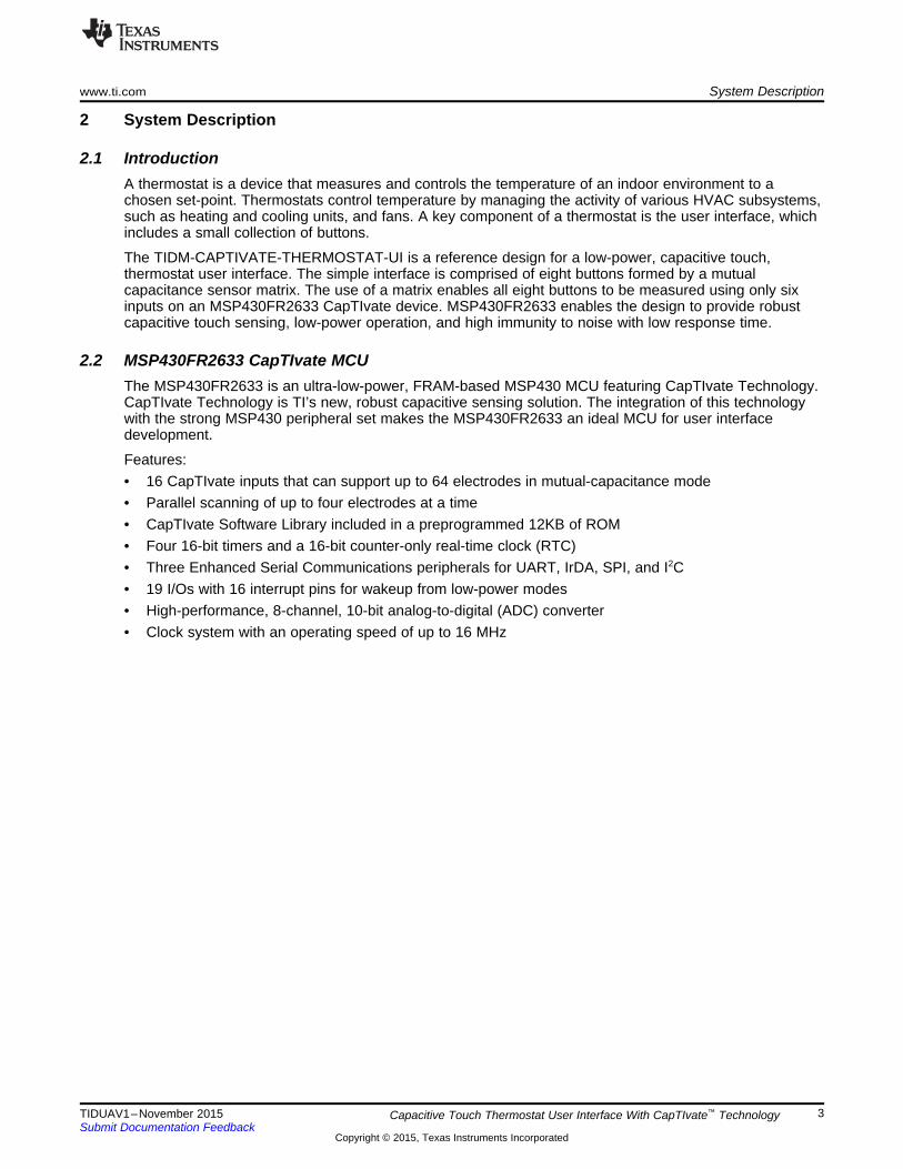
2.2 MSP430FR2633 CapTIvate MCUThe MSP430FR2633 is an ultra-low-power, FRAM-based MSP430 MCU featuring CapTIvate Technology.CapTIvate Technology is TI’s new, robust capacitive sensing solution. The integration of this technologywith the strong MSP430 peripheral set makes the MSP430FR2633 an ideal MCU for user interfacedevelopment.
Features:• 16 CapTIvate inputs that can support up to 64 electrodes in mutual-capacitance mode• Parallel scanning of up to four electrodes at a time• CapTIvate Software Library included in a preprogrammed 12KB of ROM• Four 16-bit timers and a 16-bit counter-only real-time clock (RTC)• Three Enhanced Serial Communications peripherals for UART, IrDA, SPI, and I2C• 19 I/Os with 16 interrupt pins for wakeup from low-power modes• High-performance, 8-channel, 10-bit analog-to-digital (ADC) converter• Clock system with an operating speed of up to 16 MHz
3TIDUAV1–November 2015 Capacitive Touch Thermostat User Interface With CapTIvate™ TechnologySubmit Documentation Feedback
Copyright © 2015, Texas Instruments Incorporated

LED
Relay driver
Temperature sensor Wi-Fi radio
Humidity sensor
MPU
Sub 1-GHz or 2.4-GHz radio
Load switch
Voltage supervisor
IR temp sensor
Load switch
Backlight
LCD screenLCD
driver
Ambient light sensor
LCD backlightcontroller
Light
MSP430
CaptivateMCU
FRAM saving user setting
hapticsIncluded in TI Design
Block Diagram www.ti.com
3 Block Diagram
3.1 Thermostat Block DiagramFigure 1 shows how the TIDM-CAPTIVATE-THERMOSTAT-UI is used in a thermostat design.
Figure 1. Example Thermostat Block Diagram
4 TIDUAV1–November 2015Capacitive Touch Thermostat User Interface With CapTIvate™ TechnologySubmit Documentation Feedback
Copyright © 2015, Texas Instruments Incorporated
CapSense I/O
DVCC
RST/NMI
XIN XOUT P3.x/P4.x P5.x/P6.xP1.x/P2.x P7.x/P8.x
LPM3.5 DomainSBWTDIOSBWTCK
TDOTDI/TCLK
TMSTCK
DVSS
I/O PortsP1/P2
2×8 IOsInterrupt
& WakeupPA
1×16 IOs
ADC
Up to 10-chSingle-end
10-bit200ksps
ClockSystemControl
XT1 FRAM
15KB+512B8KB+ B4KB+ B
512512
RAM
2KB1KB512B
Watchdog
SYS
TA1
Timer_A3 CC
Registers
eUSCI_A0
(UART,IrDA, SPI)
eUSCI_B0
(SPI, I2C)
CRC16
16-bitCyclic
RedundancyCheck
RTC
16-bitReal-Time
Clock
LCD
4×368×32
SegmentsJTAG
SBW
I/O PortsP3/P4
2×8 IOs
PB1×16 IOs
I/O PortsP5/P6
2×8 IOs
PC1×16 IOs
I/O PortsP7/P8
1×8 IOs
PD1×12 IOs
1×4 IOs
TA0
Timer_A3 CC
Registers
EEM
MAB
MDB
16-MHZ CPUinc.
16 Registers
PowerManagement
Module
www.ti.com Block Diagram
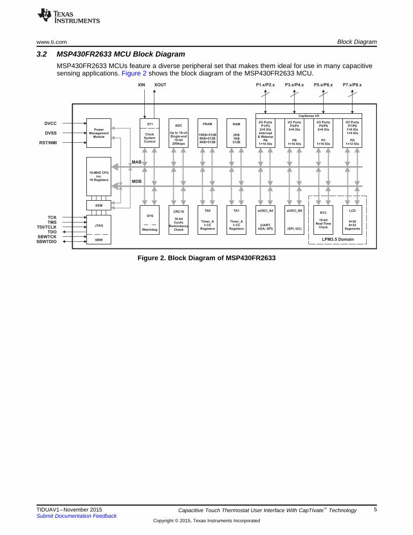
3.2 MSP430FR2633 MCU Block DiagramMSP430FR2633 MCUs feature a diverse peripheral set that makes them ideal for use in many capacitivesensing applications. Figure 2 shows the block diagram of the MSP430FR2633 MCU.
Figure 2. Block Diagram of MSP430FR2633
5TIDUAV1–November 2015 Capacitive Touch Thermostat User Interface With CapTIvate™ TechnologySubmit Documentation Feedback
Copyright © 2015, Texas Instruments Incorporated

���d/À���¡�d��Zv}o}PÇ��}��
���d/À���¡�d��Zv}o}PÇ
Measurement Block(s)
Block n
Block 2
Block 1
Event Timer
Reference
Capacitors
Conversion
Control
+
Finite State
Machine
Logic
Dedicated LDO
RegulatorVoltage
Reference
Low Frequency Clock
Interrupt Request
MSP Peripheral Bus
Cx
Cm
IO
Mux
Tx
Rx
Rx
Interrupt Request
MSP DVCC
Frequency
Hopping &
Spread
Spectrum
Oscillator
Mutual
Mode
Self
Mode
Block Diagram www.ti.com
3.3 CapTIvate Technology Block DiagramCapTIvate Technolagy enables capacitive sensing on the TIDM-CAPTIVATE-THERMOSTAT-UI.CapTIvate Technology is an MSP peripheral dedicated to providing robust capacitive sensingmeasurements. Figure 3 shows the block diagram of the CapTIvate peripheral.
Figure 3. CapTIvate Technology Block Diagram
6 TIDUAV1–November 2015Capacitive Touch Thermostat User Interface With CapTIvate™ TechnologySubmit Documentation Feedback
Copyright © 2015, Texas Instruments Incorporated

www.ti.com System Design Theory
4 System Design Theory
4.1 Functional Design OverviewThe TIDM-CAPTIVATE-THERMOSTAT-UI reference design uses eight mutual-capacitance sensors toimplement its 8-button thermostat user interface. A benefit of capacitive sensing in this design is that thecapacitive sensor elements in the thermostat interface require no mechanical parts, which allows for aslimmer product. The user can also use the same physical button layout for all buttons on the interface,which can act as both momentary and maintained switches. Figure 4 shows the TIDM-CAPTIVATE-THERMOSTAT-UI fully assembled with a 2.5 mm polycarbonate overlay.
Figure 4. TIDM-CAPTIVATE-THERMOSTAT-UI
The TIDM-CAPTIVATE-THERMOSTAT-UI is designed for an onboard MSP430FR2633 CapTIvate MCUwith FRAM. FRAM, also known as FeRAM, is a memory technology that combines the best of flash andstatic random-access memory (SRAM). FRAM is a nonvolatile memory that offers fast, low-power writeswith an endurance of 1015 cycles. The FRAM is used in this design to retain the configuration and state ofthe thermostat through power loss, while maintaining a low-power profile. Figure 5 shows how the MCUand the LEDs are mounted on the back of the design.
Figure 5. Bottom View of the Thermostat UI
7TIDUAV1–November 2015 Capacitive Touch Thermostat User Interface With CapTIvate™ TechnologySubmit Documentation Feedback
Copyright © 2015, Texas Instruments Incorporated

System Design Theory www.ti.com
4.2 Capacitive Touch and Mutual Capacitance TheoryCapacitive sensing is the ability to measure and detect the change in the capacitance of a sensor. Whenthis change is due to human interaction, the technique is referred to as capacitive touch sensing. Thereare two distinct implementations of capacitive sensors, self and mutual. Buttons in the thermostat interfaceare designed as mutual-capacitance sensors. Mutual capacitance sensors are composed of two separateelectrode structures, each acting as a plate in a capacitor. One electrode is referred to as a transmitelectrode (Tx) and the other is a receive (Rx) electrode.
User interaction with a mutual capacitance sensor is identified by detecting a change in the electric fieldbetween a Tx and Rx electrode. Because a person is coupled to earth ground and the human body is aconductor, a touch between the electrodes has roughly the same effect as placing a ground betweenthem. It reduces the electric field coupling between the electrodes and reduces the overall capacitance. Atouch is identified when this change in capacitance is above a specified threshold.
4.2.1 CapTIvate TechnologyCapTIvate Technology performs capacitive sensing measurements using a unique charge transfertechnique. This technique is based on the principle that a capacitor is a charge storage device. Acapacitive touch electrode holds a certain amount of charge when a specific voltage is applied to it.
CapTIvate Technology measures the amount of charge stored on an external capacitor (electrode orsensor) by charging it at a DC voltage, then transferring the stored charge into a “charge bucket” muchlarger than the external capacitor. The “charge bucket” is implemented as a large, internal samplingcapacitor. By repeating the charge and transfer process until the sampling capacitor is full, CapTIvateTechnology provides a relative measurement of the size of the external capacitor.
CapTIvate Technology can support up to 16 self-capacitance electrodes or 64 mutual-capacitanceelectrodes at the same time. CapTIvate Technology also provides a set of hardware tools foraccommodating a wide range of external capacitances. For more information on CapTIvate, see theCapTIvate Technology Guide, www.ti.com/CapTIvateTechGuide.
4.3 Noise ImmunityA major advantage of this thermostat user interface is that it is designed for increased noise immunity.Noise immunity is especially important in capacitive touch sensing applications because they must be ableto measure very small changes in capacitance. Changes in capacitance measured on a capacitivesensing electrode are often on the order of 1 pF or less. Capacitive touch circuits that might be exposed toelectrically noisy environments must be designed with noise immunity in mind to ensure they canconsistently resolve a measurement of this size.
4.3.1 Conducted RF Noise IntroductionConducted RF interference is interference that couples with a system or device by direct contact with aconductive body, such as through cables, wires, and PCB traces. A common way for conducted noise tocouple with a system that uses capacitive touch sensing is through its power supply.
Be aware of conducted RF noise when designing capacitive touch systems because it can cause theinjection of noise currents into capacitive touch I/Os. These currents can make the capacitances on theI/Os appear larger or smaller than they actually are. If a capacitive I/O is measured when this happens, afailure to detect a touch or false touch detection may occur.
4.3.2 EMC With CapTIvate TechnologyWhen capacitive sensors are measured by an MCU, they are generally measured at a specific scanfrequency. Scanning sensors at a single frequency results in high susceptibility to conducted noise thatpropagates near the scan frequency or its harmonics. To prevent this from happening, the CapTIvateTechnology enables frequency hopping, which is the ability to scan capacitive sensors at up to fourdifferent frequencies. Each scan frequency used results in a separate measurement of the sensor. Whenconducted noise impacts data from one of the measurements, data from the other measurements can beused to detect the noise and resolve a proper measurement with a multi-frequency processing (MFP)algorithm.
8 TIDUAV1–November 2015Capacitive Touch Thermostat User Interface With CapTIvate™ TechnologySubmit Documentation Feedback
Copyright © 2015, Texas Instruments Incorporated
www.ti.com System Design Theory
Frequency hopping is just one of the EMC features provided by the CapTIvate peripheral. For moreinformation on the EMC features provided by the CapTIvate Technology, see the CapTIvate TechnologyGuide, www.ti.com/CapTIvateTechGuide.
4.3.3 Filter ElementsThe TIDM-CAPTIVATE-THERMOSTAT-UI uses 68 pF capacitors to ground on the CapTIvate I/O Rx linesto further increase noise immunity. These capacitors provide stability to Rx lines by providing a shunt pathto circuit return for noise currents. The observed effect of adding the capacitors is a reduction in the widthof the band of frequencies, around each scan frequency, in which noise can impact sensormeasurements. For mutual capacitance designs with CapTIvate Technology, it is recommended to includeprovisions for a 33 pF to 68 pF capacitor to circuit ground in case they are required during development.Using a capacitor closer to 68 pF provides the most reduction in width, but it also contributes more toparasitic capacitance.
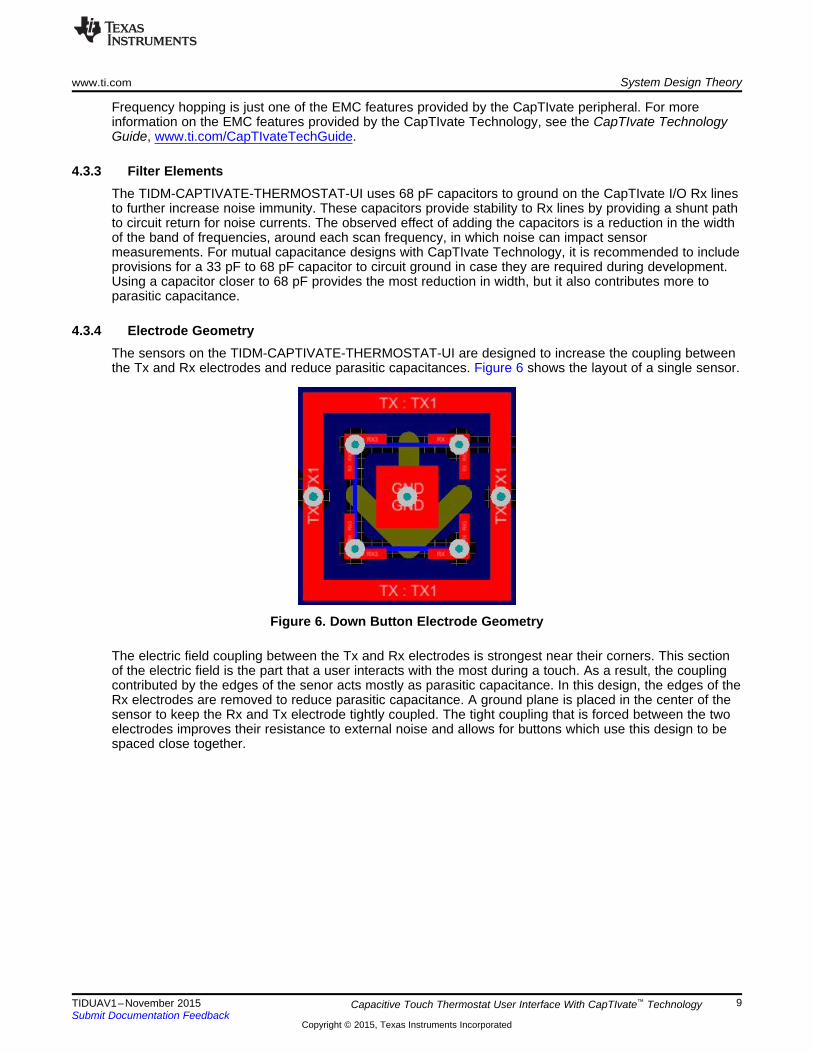
4.3.4 Electrode GeometryThe sensors on the TIDM-CAPTIVATE-THERMOSTAT-UI are designed to increase the coupling betweenthe Tx and Rx electrodes and reduce parasitic capacitances. Figure 6 shows the layout of a single sensor.
Figure 6. Down Button Electrode Geometry
The electric field coupling between the Tx and Rx electrodes is strongest near their corners. This sectionof the electric field is the part that a user interacts with the most during a touch. As a result, the couplingcontributed by the edges of the senor acts mostly as parasitic capacitance. In this design, the edges of theRx electrodes are removed to reduce parasitic capacitance. A ground plane is placed in the center of thesensor to keep the Rx and Tx electrode tightly coupled. The tight coupling that is forced between the twoelectrodes improves their resistance to external noise and allows for buttons which use this design to bespaced close together.
9TIDUAV1–November 2015 Capacitive Touch Thermostat User Interface With CapTIvate™ TechnologySubmit Documentation Feedback
Copyright © 2015, Texas Instruments Incorporated
Getting Started With Hardware www.ti.com
5 Getting Started With HardwareThe TIDM-CAPTIVATE-THERMOSTAT-UI will not be sold on the TI store. Hardware design files areprovided with the TI Design so that it may be replicated. Alternatively, an MSP-CAPT-FR2633Development Kit can be purchased to evaluate the CapTIvate Technology in a wide range of capacitivetouch configurations. The kit includes a CapTIvate MCU EVM and multiple touch panels that demonstratethe use of CapTIvate Technology in different capacitive touch applications. These touch panels interfacedirectly into the EVM for easy plug-and-play use.
Unlike the touch panels included in the MSP-CAPT-FR2633, the TIDM-CAPTIVATE-THERMOSTAT-UIwas designed with an onboard MSP430FR2633 instead of with an interface to the CapTIvate MCU EVM.This was done to improve noise immunity. A large connector between the panel and the EVM would havebeen a significant source of noise. To use the TIDM-CAPTIVATE-THERMOSTAT-UI, plug it directly intoan CAPTIVATE-PGMR.
6 Getting Started With FirmwareThe example firmware developed for the TIDM-CAPTIVATE-THERMOSTAT-UI was developed using CCSv6.1.0.00104 and TI Compiler version 4.4.3. To evaluate the example firmware, download the latestversion of CCS. The example projects can be imported into a CCS workspace from [TI Design SoftwareInstall Root]/Firmware/Source/*.
6.1 Thermostat Application–Stand-aloneThe source code of the demo application for the thermostat is organized in multiple files, listed in Table 2.
Table 2. Source Code Files for Demo Application
NAME DESCRIPTIONmain.c Application main function
Thermostat_UI_Demo.h Demo initialization and typdefs header fileThermostat_UI_Demo.c Demo initialization and touch event handler fileThermostat_UI_LEDs.h LED definitions and macros header fileThermostat_UI_LEDs.c LED update function file
The demo application simulates a programmable thermostat with control over temperature, a fan unit, anda heating and cooling unit. The states of the units that the thermostat controls are displayed through theLEDs on the touch panel. Although the TIDM-CAPTIVATE-THERMOSTAT-UI cannot display the selectedtemperature, it is maintained as a variable in FRAM for debug purposes. Each time the UP and DOWNbuttons are pressed, the temperature variable increases or decreases by one degree, respectively.
NOTE: Tuning of the keypad in the examples was set for a TIDM-CAPTIVATE-THERMOSTAT-UIassembled with a 2.54-mm polycarbonate cover over the buttons.
Two example CCS projects are provided that run the stand-alone thermostat demo application usingdifferent sensor configurations.
6.1.1 Wall-power ExampleThe wall-power example project runs the thermostat demo application with the conducted noise immunityfeature of the CapTIvate Software Library enabled. The wall-power example also uses heavy debouncingand filtering to ensure that noisy samples have a smaller impact on performance. A small scan delay isused to ensure the design responds quickly to touch even with the increased requirements formeasurement time and post-processing.
10 TIDUAV1–November 2015Capacitive Touch Thermostat User Interface With CapTIvate™ TechnologySubmit Documentation Feedback
Copyright © 2015, Texas Instruments Incorporated

www.ti.com Getting Started With Firmware
6.1.2 Battery-power ExampleThe battery-power example keeps noise immunity off and uses an extended scan delay to reduce CPUactivity. No debounce and minimal filtering is used in the battery-power example to keep response timelow with higher scan delay. The battery-power configuration uses significantly less power, but it providesless protection against noise. The trade off between power and noise immunity is made in an applicationsuch as a battery-powered thermostat remote.
6.2 Thermostat Application–With TIDM-FRAM-THERMOSTATA capacitive touch microcontroller may act as a main application processor, or it could simply be used asa dedicated human-machine interface (HMI). An example project is provided with the TIDM-CAPTIVATE-THERMOSTAT-UI that demonstrates how it could be used as a dedicated HMI for TIDM-FRAM-THERMOSTAT. Separate source code is provided for the TIDM-FRAM-THERMOSTAT that includesmaster I2C drivers for interfacing with the touch panel.
When using the two together, the LCD of the TIDM-FRAM-THERMOSTAT can be controlled with theTIDM-CAPTIVATE-THERMOSTAT-UI. Figure 7 shows the application running using the designs.
Figure 7. TIDM-CAPTIVATE-THERMOSTAT-UI With TIDM-FRAM-THERMOSTAT
11TIDUAV1–November 2015 Capacitive Touch Thermostat User Interface With CapTIvate™ TechnologySubmit Documentation Feedback
Copyright © 2015, Texas Instruments Incorporated
Testing www.ti.com
The application requires the powering of the TIDM-CAPTIVATE-THERMOSTAT-UI by the TIDM-FRAM-THERMOSTAT. Power the TIDM-CAPTIVATE-THERMOSTAT with the TIDM-FRAM-THERMOSTAT byconnecting the designs using female-to-male jumper wires. Table 3 shows a complete list of connectionsthat are required to interface the designs.
Table 3. Required Device Connections
TIDM-FRAM-THERMOSTAT TIDM-CAPTIVATE-THERMOSTAT-UIVCC VCCGND GND
SDA/SIMO (P5.2) SDA (P1.2)SCL/SOMI (P5.3) SCL (P1.3)
GPIO 0 (P1.2) IRQ (P1.1)
7 TestingThis section describes the testing that was performed on the TIDM-CAPTIVATE-THERMOSTAT-UI. Itincludes descriptions of test setups and results for conducted RF immunity testing, power profiling, andresponse time measurement.
7.1 Conducted RF Immunity Testing (IEC 61000-4-6)IEC 61000-4-6 specifies constraints for a conducted noise immunity test over a range of 150 kHz to 80MHz. The TIDM-CAPTIVATE-THERMOSTAT-UI was tested for conducted noise in the range of 300 kHzto 80 MHz.
7.1.1 Pass/Fail CriteriaA class B pass for the IEC 61000-4-6 requires no false detects by the capacitive touch system during thetest and no unintentional resets by the MCU. Unintentional resets include unintentional MCU lockup. Aclass A pass requires no false detects allowed at any time during the test while the system detects allvalid touches. The same restrictions for unintentional resets as for class B apply for class A.
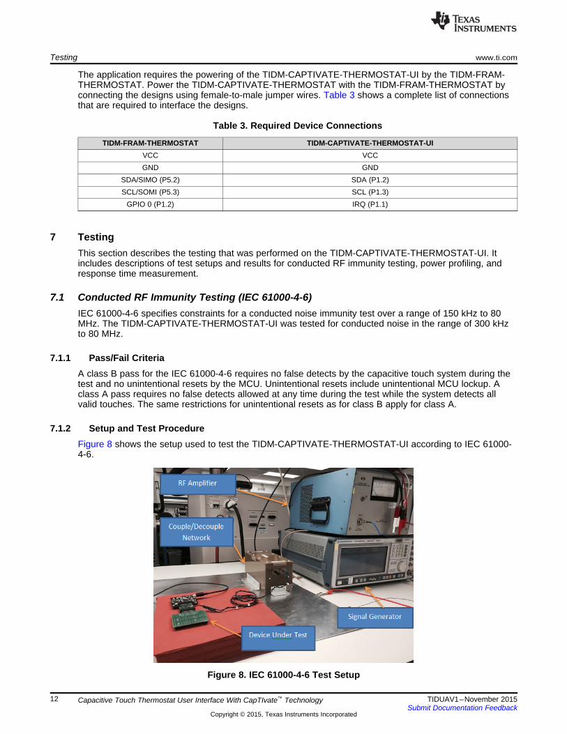
7.1.2 Setup and Test ProcedureFigure 8 shows the setup used to test the TIDM-CAPTIVATE-THERMOSTAT-UI according to IEC 61000-4-6.
Figure 8. IEC 61000-4-6 Test Setup
12 TIDUAV1–November 2015Capacitive Touch Thermostat User Interface With CapTIvate™ TechnologySubmit Documentation Feedback
Copyright © 2015, Texas Instruments Incorporated

www.ti.com Testing
In the setup, the board is approximately 10 cm above earth ground and is powered from acouple/decouple network that couples noise to the output of the power supply (power supply is not shownin Figure 8). A signal generator was used to generate a sinusoidal noise sweep from 300 kHz to 80 MHz,amplitude modulated on a 1 kHz sinusoidal carrier frequency at 80% depth. An RF amplifier was used tobring the noise signal up to a 3 Vrms stress level.
Data from the sensors on the touch panel was collected using the CapTIvate Design Center. The touchpanel was connected to the Design Center GUI through the back channel UART through an CAPTIVATE-PGMR. The CAPTIVATE-PGMR was independently powered and isolated from the touch panel powersupply with a CAPTIVATE-ISO isolation board during testing.
In the first test, measurements of an untouched button on the touch panel were recorded at four scanfrequencies while noise was injected into the power supply. The measurements were continuouslyrecorded while a frequency sweep was performed on the noise across the range of 300 kHz to 80 MHz.During the test, no false touches were recorded on any of the buttons. Figure 9 shows the raw datacollected at each scan frequency.
Figure 9. Untouched, Raw Data (Counts vs Time)
Disruptions in the raw data can be seen at various points during the frequency sweep. The first four peakscan be identified as points when the noise coupled with the power supply was at a fundamental scanfrequency. The smaller peaks that occur in later samples can be understood to be points when the noisewas at harmonics of the four scan frequencies. Though measurements from each individual scanfrequency were disrupted by the noise, the processed measurement remained consistent throughout thesweep, as shown in Figure 10.
Figure 10. Untouched, Processed Data (Counts vs Time)
13TIDUAV1–November 2015 Capacitive Touch Thermostat User Interface With CapTIvate™ TechnologySubmit Documentation Feedback
Copyright © 2015, Texas Instruments Incorporated
Testing www.ti.com
Throughout the frequency sweep, the filtered count value was steady and below the threshold value. Thesensor constantly recorded no touch throughout the test, as expected.
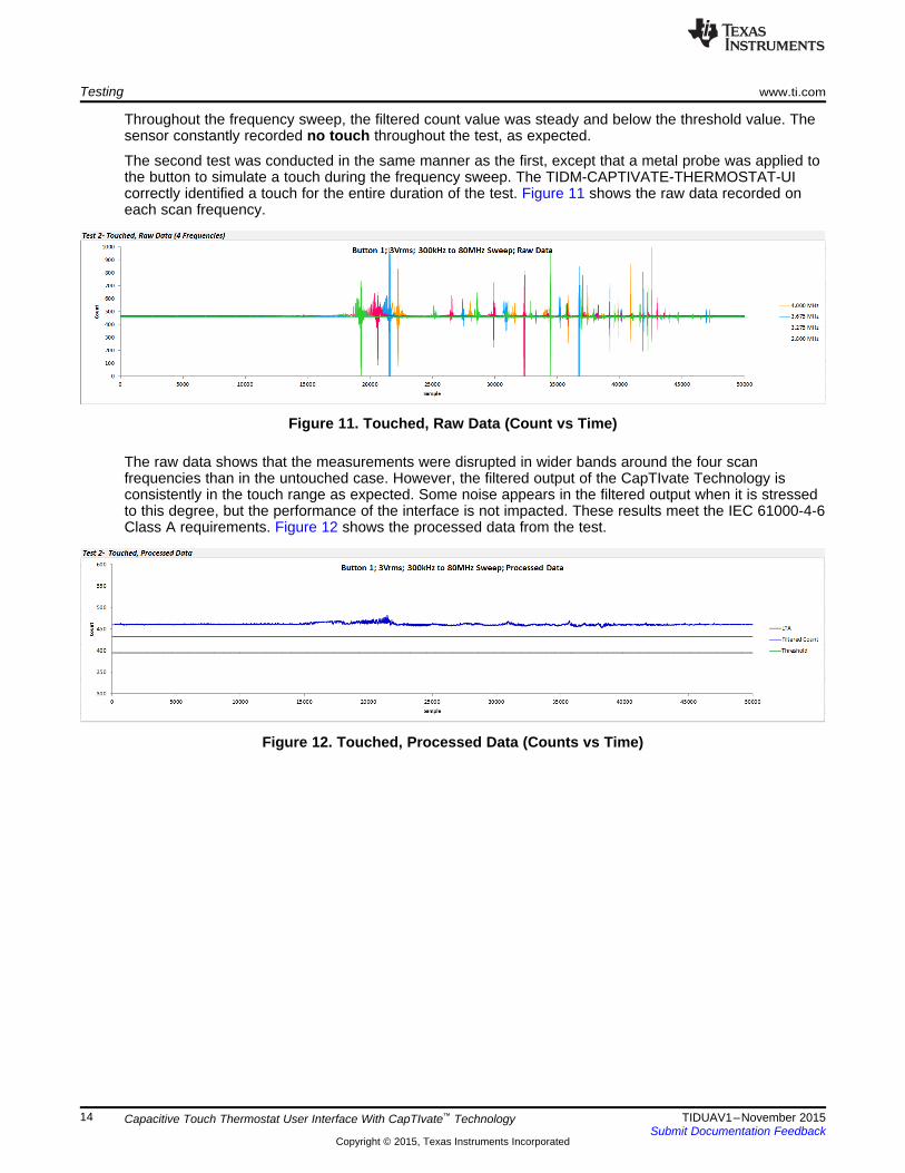
The second test was conducted in the same manner as the first, except that a metal probe was applied tothe button to simulate a touch during the frequency sweep. The TIDM-CAPTIVATE-THERMOSTAT-UIcorrectly identified a touch for the entire duration of the test. Figure 11 shows the raw data recorded oneach scan frequency.
Figure 11. Touched, Raw Data (Count vs Time)
The raw data shows that the measurements were disrupted in wider bands around the four scanfrequencies than in the untouched case. However, the filtered output of the CapTIvate Technology isconsistently in the touch range as expected. Some noise appears in the filtered output when it is stressedto this degree, but the performance of the interface is not impacted. These results meet the IEC 61000-4-6Class A requirements. Figure 12 shows the processed data from the test.
Figure 12. Touched, Processed Data (Counts vs Time)
14 TIDUAV1–November 2015Capacitive Touch Thermostat User Interface With CapTIvate™ TechnologySubmit Documentation Feedback
Copyright © 2015, Texas Instruments Incorporated

www.ti.com Testing
7.2 Power ProfilePower profiles for the TIDM-CAPTIVATE-THERMOSTAT-UI in each provided example application werecollected using a DC Power Analyzer. The DC Power Analyzer was used to supply a 3.3-V input voltageto the touch panel and measure current consumption. For the power testing, the LEDs that are normallyused to indicate touch on the design were kept off. The example software can be run in the power testingmode by uncommenting the POWER_TESTING symbol in the Thermostat_UI_Demo.h file. The LEDswere kept off while testing to provide a better representation of the power consumption of theMSP430FR2633 CapTIvate MCU with the different configurations. The LEDs were also kept off becausethey are not an integral part of the design and could be removed in an end-product. Figure 13 shows thecurrent consumption for the design while running the battery-powered example.
Figure 13. Power Profile for Battery-powered Example, Two Measurements (Current vs Time)
15TIDUAV1–November 2015 Capacitive Touch Thermostat User Interface With CapTIvate™ TechnologySubmit Documentation Feedback
Copyright © 2015, Texas Instruments Incorporated
Testing www.ti.com
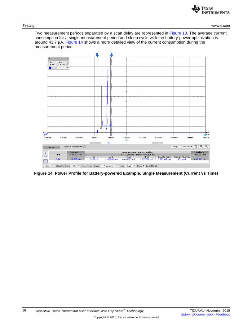
Two measurement periods separated by a scan delay are represented in Figure 13. The average currentconsumption for a single measurement period and sleep cycle with the battery-power optimization isaround 43.7 µA. Figure 14 shows a more detailed view of the current consumption during themeasurement period.
Figure 14. Power Profile for Battery-powered Example, Single Measurement (Current vs Time)
16 TIDUAV1–November 2015Capacitive Touch Thermostat User Interface With CapTIvate™ TechnologySubmit Documentation Feedback
Copyright © 2015, Texas Instruments Incorporated

www.ti.com Testing
The maximum current consumption occurs while the device is measuring the buttons on the keypadsensor. Two distinct peaks in current occur during these times, because the buttons on the sensors areorganized into two separate measurement cycles. Therefore, two measurement cycles are needed toupdate the status of the entire keypad. The amount of time required to measure the buttons in this battery-powered mode is much shorter than in the wall-powered mode because the buttons are scanned at onlyone frequency. Figure 15 shows the current consumption in the wall-powered mode.
Figure 15. Power Profile for Wall-Powered Example (Current vs Time)
17TIDUAV1–November 2015 Capacitive Touch Thermostat User Interface With CapTIvate™ TechnologySubmit Documentation Feedback
Copyright © 2015, Texas Instruments Incorporated
Testing www.ti.com
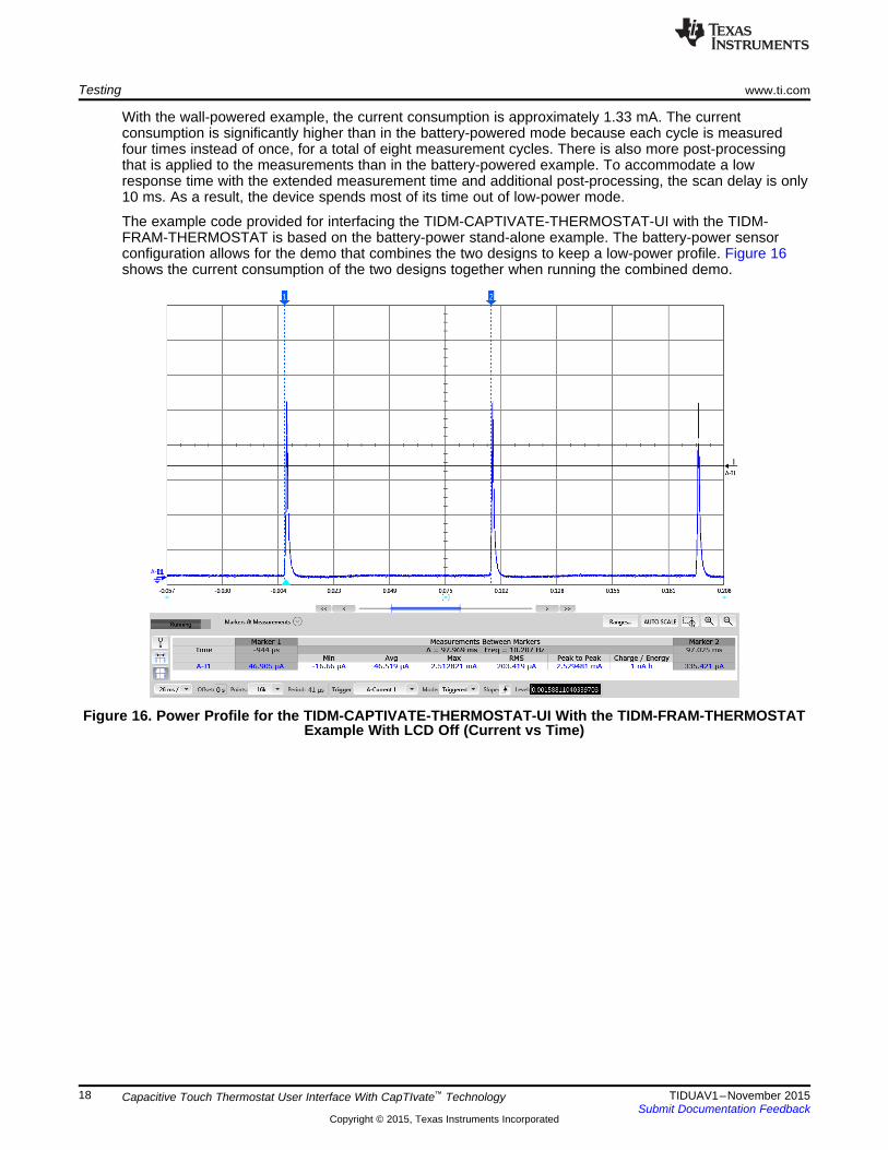
With the wall-powered example, the current consumption is approximately 1.33 mA. The currentconsumption is significantly higher than in the battery-powered mode because each cycle is measuredfour times instead of once, for a total of eight measurement cycles. There is also more post-processingthat is applied to the measurements than in the battery-powered example. To accommodate a lowresponse time with the extended measurement time and additional post-processing, the scan delay is only10 ms. As a result, the device spends most of its time out of low-power mode.
The example code provided for interfacing the TIDM-CAPTIVATE-THERMOSTAT-UI with the TIDM-FRAM-THERMOSTAT is based on the battery-power stand-alone example. The battery-power sensorconfiguration allows for the demo that combines the two designs to keep a low-power profile. Figure 16shows the current consumption of the two designs together when running the combined demo.
Figure 16. Power Profile for the TIDM-CAPTIVATE-THERMOSTAT-UI With the TIDM-FRAM-THERMOSTATExample With LCD Off (Current vs Time)
18 TIDUAV1–November 2015Capacitive Touch Thermostat User Interface With CapTIvate™ TechnologySubmit Documentation Feedback
Copyright © 2015, Texas Instruments Incorporated

www.ti.com Testing
As shown in Figure 16, the current consumption of the demo when the LCD is off is approximately 46.5µA. The amount of current consumption is possible because the TIDM-FRAM-THERMOSTAT is onlypulled out of its low-power mode (LPM3) when it must make a new temperature measurement or updatethe LCD. While in LPM3, the TIDM-FRAM-THERMOSTAT draws less than 3 µA on average. Figure 17shows how the power consumption increases when the LCD is on.
Figure 17. Power Profile for the TIDM-CAPTIVATE-THERMOSTAT-UI With the TIDM-FRAM-THERMOSTATExample With LCD On (Current vs Time)
The power profile of the demo when the LCD is turned on is identical to when it is off, except with anadditional 5.7 µA of baseline current used to power the LCD. The total average current is 52.2 µA, whichis low enough for approximately 2 years of lifetime on AAA batteries.
19TIDUAV1–November 2015 Capacitive Touch Thermostat User Interface With CapTIvate™ TechnologySubmit Documentation Feedback
Copyright © 2015, Texas Instruments Incorporated

Testing www.ti.com
7.3 Response TimeResponse time is the amount of delay between a touch on a user interface and the response to that touch.The response time of an interface often has a big impact on user experience. When developing capacitivetouch interfaces, response time should be kept as low as possible.
The worst-case response time of the TIDM-CAPTIVATE-THERMOSTAT-UI was evaluated for the wall-power and battery-power applications. Worst-case response time is characterized by a touch on a buttonmade immediately after a measurement of that button completes. The resulting worst-case delay can beestimated by adding the delay between proximity detection and touch detection to the scan period. Theestimate is actually an overestimate of typical response time because proximity detection normally occursbefore a touch occurs. It is also a worst-case response time because most touches would not occur a fullscan period before measurement.
In the battery-power application, no delay was observed between proximity detection and a registeredtouch. No delay is observed because there are no debounce features and minimal filtering is performed onmeasurements in battery mode to keep power consumption low. The scan period is set to 0.1 second inthe battery application. As a result, the worst-case response time is dominated by the scan period and isapproximately 0.1 second.
In the wall-power application, heavy debouncing and filtering are used to decrease susceptibility to noisymeasurements. The post-processing of measurements causes the delay between detecting proximity andregistering a touch to vary according to the speed and nature of a touch. The delay is smaller when afinger approaches the panel quickly. The delay is also smaller when the surface area of a touch is larger.
The worst-case response time for the wall-power configuration was evaluated by measuring the responsetime for a set of 10 touches. Table 4 provides the data collected during the testing.
Table 4. Wall-Power Response Time Measurements
SCANTOUCH PROXIMITY TO TOUCH DETECTION DELAY APPROXIMATE TOTAL RESPONSEPERIODNUMBER (SECONDS) TIME (SECONDS)(SECONDS)1 .0880 .09802 .0782 .08823 .0684 .07844 .0684 .07845 .1173 .12736 .1076 .010 .11767 .0782 .08828 .0978 .10789 .2054 .215410 .0978 .1078
Avg 0.1007 0.1107
As seen in Table 4, the response time for the wall-power application was dominated by the measurementtime and post-processing performed by the CapTIvate Technology. The result is an average approximateresponse time of 0.1107 seconds. Table 5 lists the response times in the battery-power application andwall-power application for comparison.
Table 5. Response Time Comparison
CONFIGURATION APPROXIMATE RESPONSE TIME (SECONDS)Battery-power application 0.10
Wall-power application 0.11 average
20 TIDUAV1–November 2015Capacitive Touch Thermostat User Interface With CapTIvate™ TechnologySubmit Documentation Feedback
Copyright © 2015, Texas Instruments Incorporated
RST/NMI/SBWTDIO1
TEST/SBWTCK2
DVCC32
DVSS31
VREG20
P3.0/CAP0.012
CAP0.113
P2.3/CAP0.214
CAP0.315
P3.1/UCA1STE/CAP1.016
P2.4/UCA1CLK/CAP1.117
P2.5/UCA1RXD/UCA1SOMI/CAP1.218
P2.6/UCA1TXD/UCA1SIMO/CAP1.319
CAP2.021
P2.7/CAP3.025
CAP3.126
P3.2/CAP3.227
CAP3.328
MSP430FR2633IRHB32VQFN
CAP2.122
CAP2.223
CAP2.324
P1.0/UCB0STE/TA0CLK/A07
P1.1/UCB0CLK/TA0.1/A18
P1.2/UCB0SIMO/UCB0SDA/TA0.2/A29
P1.3/UCB0SOMI/UCB0SCL/MCLK/A310
P1.4/UCA0TXD/UCA0SIMO/TA1.2/A43
P1.5/UCA0RXD/UCA0SOMI/TA1.1/A54
P1.6/UCA0CLK/TA1CLK/A65
P1.7/UCA0STE/SMCLK/A76
P2.0/XOUT29
P2.1/XIN30
CAPTIVATE MCU
P2.2/SYNC/ACLK11
PAD33
U1
MSP430FR2633IRHB
VCC_MSP
GND
VREG
GND
VCC_MSP
RST
RSTTEST
1 2
3 4
5 6
7 8
9 10
11 12
13 14
15 16
17 18
19 20
J1
Connector 10X2RA
RST TEST
SYNC IRQ
TXDRXDSCL SDA
GNDGND
SDA
SCL
IRQ
VCC_LDO
IRQSDASCLTXDRXD
SYNC
TX
RX
GND
E1
Btn-Mutual-EMC
470R11
68pFC8
0R12 RX3
GND
470R9
68pFC7
0R10 RX2
GND
470R7
68pFC6
0R8 RX1
GND
470R5
68pFC5
0R6 RX0
GND
470R13
68pFC9DNP
0R14 TX0
GND
470R15
68pFC10DNP
0R16 TX1
GND
GND
RX3TX0 TX
RX
GND
E2
Btn-Mutual-EMC
GND
RX2TX0 TX
RX
GND
E3
Btn-Mutual-EMC
GND
RX1TX0 TX
RX
GND
E4
Btn-Mutual-EMC
GND
RX0TX0
TX
RX
GND
E5
Btn-Mutual-EMC
GND
RX3TX1 TX
RX
GND
E6
Btn-Mutual-EMC
GND
RX2TX
RX
GND
E7
Btn-Mutual-EMC
GND
RX1TX
RX
GND
E8
Btn-Mutual-EMC
GND
RX0TX1 TX1 TX1
LED6
LED8LED7
LED1LED5
LED4LED3LED2
1 2
D1
Green LED
1 2
D3
Green LED
1 2
D5
Green LED
1 2
D7
Green LED
LED1
LED3
LED5
LED7
1 2
D2
Green LED
1 2
D4
Green LED
1 2
D6
Green LED
1 2
D8
Green LED
LED2
LED4
LED6
LED8
510
R17
510
R19
510
R21
510
R23
510
R18
510
R20
510
R22
510
R24
VCC_MSP VCC_MSP
0.1µFC2
1µFC3
4.7µFC14.7k
R2
4.7k
R3
4.7k
R4
47kR1
510pFC4
1
2
3
J2
TSW-103-07-G-S
TP2 TP1
VCC_METEREDVCC_MSPVCC_LDO
GND
VCC_METERED
VCC_LDO
GND
www.ti.com Design Files
8 Design Files
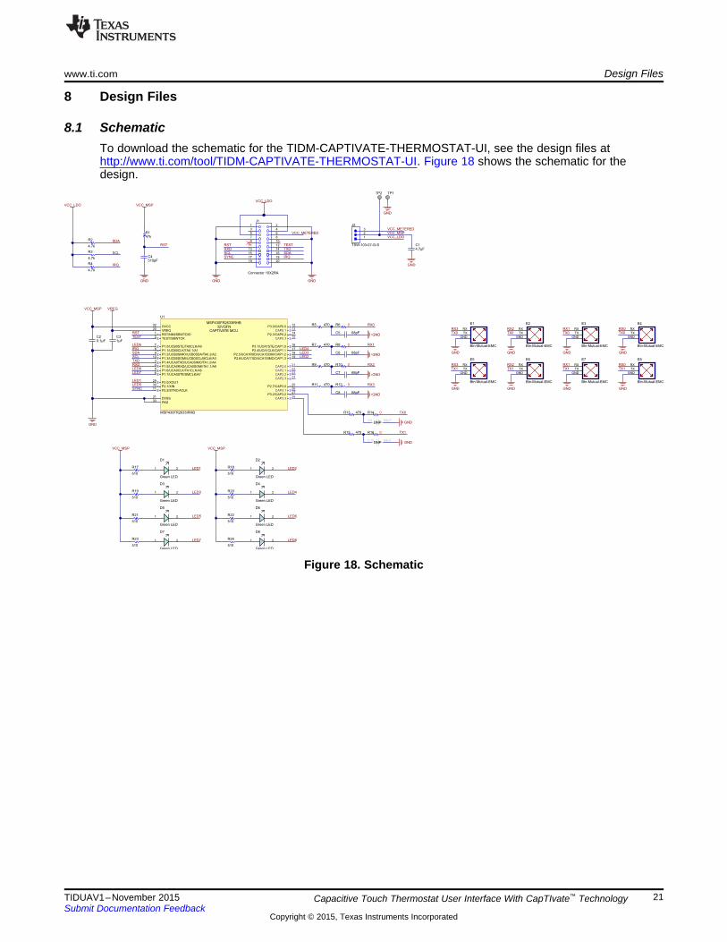
8.1 SchematicTo download the schematic for the TIDM-CAPTIVATE-THERMOSTAT-UI, see the design files athttp://www.ti.com/tool/TIDM-CAPTIVATE-THERMOSTAT-UI. Figure 18 shows the schematic for thedesign.
Figure 18. Schematic
21TIDUAV1–November 2015 Capacitive Touch Thermostat User Interface With CapTIvate™ TechnologySubmit Documentation Feedback
Copyright © 2015, Texas Instruments Incorporated

Design Files www.ti.com
8.2 Bill of MaterialsTo download the bill of materials for the TIDM-CAPTIVATE-THERMOSTAT-UI, see the design files athttp://www.ti.com/tool/TIDM-CAPTIVATE-THERMOSTAT-UI.
Table 6. Bill of Materials
DESIGN PACKAGEQUANTITY VALUE DESCRIPTION PART NUMBER MANUFACTURERATOR REFERENCECAP, CERM, 4.7 C1005X5R0J475MC1 1 µF, 6.3 V, +/- 20%, 0402 TDK050BCX5R, 0402CAP, CERM, 0.1
C2 1 µF, 6.3 V, +/- 10%, 0402 C1005X5R0J104K TDKX5R, 0402
CAP, CERM, 1 µF,C3 1 6.3 V, +/- 20%, 0402 C1005X5R0J105M TDK
X5R, 0402CAP, CERM, 510 GRM1555C1E511C4 1 pF, 25 V, +/- 5%, 0402 MuRataJA01DC0G/NP0, 0402
CAP, CERM, 68 pF,C5, C6, GRM1555C1H6804 50 V, +/- 5%, 0402 MuRataC7, C8 JA01DC0G/NP0, 0402D1, D2, LED, Green, SMD,D3, D4, 8 Reverse Mount, 1206 597-6301-607F DialightD5, D6, 1206D7, D8FID1, Fiducial mark. ThereFID2, 3 is nothing to buy or Fiducial N/A N/AFID3 mount.
Connector, Female, SSW-110-22-F-D-J1 1 10-Pin, 2 row, Right SamtecRAAngleHeader, 100mil,J2 1 3×1 Header TSW-103-07-G-S Samtec3x1, Gold, THRES, 47 k, 5%, CRCW040247K0JR1 1 0402 Vishay-Dale0.063 W, 0402 NED
R2, R3 RES, 4.7 k, 5%, CRCW04024K70J3 0402 Vishay-DaleR4 0.063 W, 0402 NEDR5, R7, RES, 470, 5%, CRCW0402470RJR9, R11, 6 0402 Vishay-Dale0.063 W, 0402 NEDR13, R15R6, R8, RES, 0, 5%, 0.063 CRCW04020000ZR10, R12, 6 0402 Vishay-DaleW, 0402 0EDR14, R16
R17, R18,R19, R20, RES, 510, 5%, CRCW0402510RJ8 0402 Vishay-DaleR21, R22, 0.063 W, 0402 NEDR23, R24
PCB Pin, Swage 2505-2-00-44-00-TP1, TP2 2 PCB Pin(2505-2) Mill-MaxMount, TH 00-07-0MSP430 Captivate MSP430FR2633IRU1 1 RHB (32VQFN) Texas InstrumentsMicrocontroller HB
22 TIDUAV1–November 2015Capacitive Touch Thermostat User Interface With CapTIvate™ TechnologySubmit Documentation Feedback
Copyright © 2015, Texas Instruments Incorporated
www.ti.com Design Files
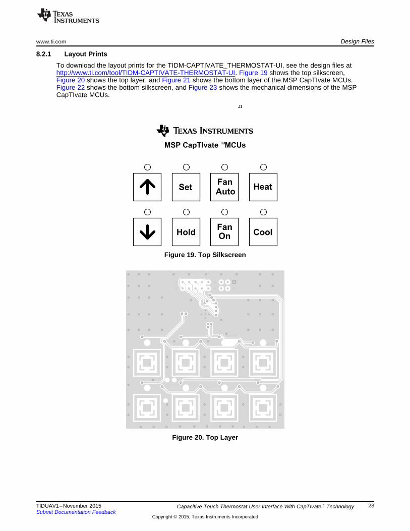
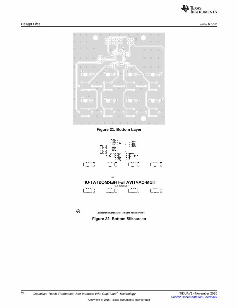
8.2.1 Layout PrintsTo download the layout prints for the TIDM-CAPTIVATE_THERMOSTAT-UI, see the design files athttp://www.ti.com/tool/TIDM-CAPTIVATE-THERMOSTAT-UI. Figure 19 shows the top silkscreen,Figure 20 shows the top layer, and Figure 21 shows the bottom layer of the MSP CapTIvate MCUs.Figure 22 shows the bottom silkscreen, and Figure 23 shows the mechanical dimensions of the MSPCapTIvate MCUs.
Figure 19. Top Silkscreen
Figure 20. Top Layer
23TIDUAV1–November 2015 Capacitive Touch Thermostat User Interface With CapTIvate™ TechnologySubmit Documentation Feedback
Copyright © 2015, Texas Instruments Incorporated
Design Files www.ti.com
Figure 21. Bottom Layer
Figure 22. Bottom Silkscreen
24 TIDUAV1–November 2015Capacitive Touch Thermostat User Interface With CapTIvate™ TechnologySubmit Documentation Feedback
Copyright © 2015, Texas Instruments Incorporated

www.ti.com Design Files
Figure 23. Mechanical Dimensions
25TIDUAV1–November 2015 Capacitive Touch Thermostat User Interface With CapTIvate™ TechnologySubmit Documentation Feedback
Copyright © 2015, Texas Instruments Incorporated

Design Files www.ti.com
8.3 Altium ProjectTo download the altium project files for the TIDM-CAPTIVATE-THERMOSTAT-UI, see the design files athttp://www.ti.com/tool/TIDM-CAPTIVATE-THERMOSTAT-UI. Figure 24 shows the front of the layout, andFigure 25 shows the back of the layout of the MSP CapTIvate MCUs.
Figure 24. Front of Layout
Figure 25. Back of Layout
26 TIDUAV1–November 2015Capacitive Touch Thermostat User Interface With CapTIvate™ TechnologySubmit Documentation Feedback
Copyright © 2015, Texas Instruments Incorporated

www.ti.com Software Files
9 Software FilesTo download the software files for this reference design, see the link at http://www.ti.com/tool/TIDM-CAPTIVATE-THERMOSTAT-UI.
10 References1. Texas Instruments CapTIvate Design Center, http://www.ti.com/captivate2. Texas Instruments E2E Community, http://e2e.ti.com/
11 Terminology• Self capacitance– The method of measuring changes in capacitance with respect to earth ground.• Mutual capacitance– Involves measuring the change in capacitance on a sensor structure in which
both plates of the capacitor are defined by electrode structures.• Noise Immunity– The ability to maintain proper operation in an electrically noisy environment.
27TIDUAV1–November 2015 Capacitive Touch Thermostat User Interface With CapTIvate™ TechnologySubmit Documentation Feedback
Copyright © 2015, Texas Instruments Incorporated

About the Author www.ti.com
12 About the AuthorBENJAMIN MOORE is an Applications Engineer at Texas Instruments on the MSP MicrocontrollerSystem Applications Team. Benjamin earned his Bachelor of Science in Electrical and ComputerEngineering (BSECE) from The Ohio State University in Columbus, OH.
28 TIDUAV1–November 2015Capacitive Touch Thermostat User Interface With CapTIvate™ TechnologySubmit Documentation Feedback
Copyright © 2015, Texas Instruments Incorporated

IMPORTANT NOTICE FOR TI REFERENCE DESIGNS
Texas Instruments Incorporated ("TI") reference designs are solely intended to assist designers (“Buyers”) who are developing systems thatincorporate TI semiconductor products (also referred to herein as “components”). Buyer understands and agrees that Buyer remainsresponsible for using its independent analysis, evaluation and judgment in designing Buyer’s systems and products.TI reference designs have been created using standard laboratory conditions and engineering practices. TI has not conducted anytesting other than that specifically described in the published documentation for a particular reference design. TI may makecorrections, enhancements, improvements and other changes to its reference designs.Buyers are authorized to use TI reference designs with the TI component(s) identified in each particular reference design and to modify thereference design in the development of their end products. HOWEVER, NO OTHER LICENSE, EXPRESS OR IMPLIED, BY ESTOPPELOR OTHERWISE TO ANY OTHER TI INTELLECTUAL PROPERTY RIGHT, AND NO LICENSE TO ANY THIRD PARTY TECHNOLOGYOR INTELLECTUAL PROPERTY RIGHT, IS GRANTED HEREIN, including but not limited to any patent right, copyright, mask work right,or other intellectual property right relating to any combination, machine, or process in which TI components or services are used.Information published by TI regarding third-party products or services does not constitute a license to use such products or services, or awarranty or endorsement thereof. Use of such information may require a license from a third party under the patents or other intellectualproperty of the third party, or a license from TI under the patents or other intellectual property of TI.TI REFERENCE DESIGNS ARE PROVIDED "AS IS". TI MAKES NO WARRANTIES OR REPRESENTATIONS WITH REGARD TO THEREFERENCE DESIGNS OR USE OF THE REFERENCE DESIGNS, EXPRESS, IMPLIED OR STATUTORY, INCLUDING ACCURACY ORCOMPLETENESS. TI DISCLAIMS ANY WARRANTY OF TITLE AND ANY IMPLIED WARRANTIES OF MERCHANTABILITY, FITNESSFOR A PARTICULAR PURPOSE, QUIET ENJOYMENT, QUIET POSSESSION, AND NON-INFRINGEMENT OF ANY THIRD PARTYINTELLECTUAL PROPERTY RIGHTS WITH REGARD TO TI REFERENCE DESIGNS OR USE THEREOF. TI SHALL NOT BE LIABLEFOR AND SHALL NOT DEFEND OR INDEMNIFY BUYERS AGAINST ANY THIRD PARTY INFRINGEMENT CLAIM THAT RELATES TOOR IS BASED ON A COMBINATION OF COMPONENTS PROVIDED IN A TI REFERENCE DESIGN. IN NO EVENT SHALL TI BELIABLE FOR ANY ACTUAL, SPECIAL, INCIDENTAL, CONSEQUENTIAL OR INDIRECT DAMAGES, HOWEVER CAUSED, ON ANYTHEORY OF LIABILITY AND WHETHER OR NOT TI HAS BEEN ADVISED OF THE POSSIBILITY OF SUCH DAMAGES, ARISING INANY WAY OUT OF TI REFERENCE DESIGNS OR BUYER’S USE OF TI REFERENCE DESIGNS.TI reserves the right to make corrections, enhancements, improvements and other changes to its semiconductor products and services perJESD46, latest issue, and to discontinue any product or service per JESD48, latest issue. Buyers should obtain the latest relevantinformation before placing orders and should verify that such information is current and complete. All semiconductor products are soldsubject to TI’s terms and conditions of sale supplied at the time of order acknowledgment.TI warrants performance of its components to the specifications applicable at the time of sale, in accordance with the warranty in TI’s termsand conditions of sale of semiconductor products. Testing and other quality control techniques for TI components are used to the extent TIdeems necessary to support this warranty. Except where mandated by applicable law, testing of all parameters of each component is notnecessarily performed.TI assumes no liability for applications assistance or the design of Buyers’ products. Buyers are responsible for their products andapplications using TI components. To minimize the risks associated with Buyers’ products and applications, Buyers should provideadequate design and operating safeguards.Reproduction of significant portions of TI information in TI data books, data sheets or reference designs is permissible only if reproduction iswithout alteration and is accompanied by all associated warranties, conditions, limitations, and notices. TI is not responsible or liable forsuch altered documentation. Information of third parties may be subject to additional restrictions.Buyer acknowledges and agrees that it is solely responsible for compliance with all legal, regulatory and safety-related requirementsconcerning its products, and any use of TI components in its applications, notwithstanding any applications-related information or supportthat may be provided by TI. Buyer represents and agrees that it has all the necessary expertise to create and implement safeguards thatanticipate dangerous failures, monitor failures and their consequences, lessen the likelihood of dangerous failures and take appropriateremedial actions. Buyer will fully indemnify TI and its representatives against any damages arising out of the use of any TI components inBuyer’s safety-critical applications.In some cases, TI components may be promoted specifically to facilitate safety-related applications. With such components, TI’s goal is tohelp enable customers to design and create their own end-product solutions that meet applicable functional safety standards andrequirements. Nonetheless, such components are subject to these terms.No TI components are authorized for use in FDA Class III (or similar life-critical medical equipment) unless authorized officers of the partieshave executed an agreement specifically governing such use.Only those TI components that TI has specifically designated as military grade or “enhanced plastic” are designed and intended for use inmilitary/aerospace applications or environments. Buyer acknowledges and agrees that any military or aerospace use of TI components thathave not been so designated is solely at Buyer's risk, and Buyer is solely responsible for compliance with all legal and regulatoryrequirements in connection with such use.TI has specifically designated certain components as meeting ISO/TS16949 requirements, mainly for automotive use. In any case of use ofnon-designated products, TI will not be responsible for any failure to meet ISO/TS16949.IMPORTANT NOTICE
Mailing Address: Texas Instruments, Post Office Box 655303, Dallas, Texas 75265Copyright © 2015, Texas Instruments Incorporated