capa manual cfw10 - Homepage | WEG · MANUAL Series: CFW-10 Software: version 1.0X ... CHAPTER 4...
93
Frequency Inverter Convertidores de Frecuencia Inversores de Freqüência
Transcript of capa manual cfw10 - Homepage | WEG · MANUAL Series: CFW-10 Software: version 1.0X ... CHAPTER 4...

Frequency Inverter
Convertidores de Frecuencia
Inversores de Freqüência
FREQUENCYINVERTERMANUAL
Series: CFW-10Software: version 1.0X0899.5034 E/2
Please take this page out when
unpacking the product

03/2005
FREQUENCYINVERTERMANUAL
Series: CFW-10Software: version 1.0X0899.5034 E/2
ATTENTION!It is very important to check if the
inverter software version is the
same as indicated above.

4
The table below describes all revisions made to this manual.
Revision Description Section1 First Edition -2 Addition of the CFW10 MECII and -
addition of the EMC filter for MECI.General revision.
Sumarry of Revisions

CONTENTS
Quick Parameter Reference,Fault and Status Messages
I Parameters ..................................................................08II Fault Messages ........................................................... 11III Other Messages.......................................................... 11
CHAPTER 1Safety Notices
1.1 Safety Notices in the Manual ....................................121.2 Safety Notice on The Product ...................................121.3 Preliminary Recommendations .................................12
CHAPTER 2General Information
2.1 About this Manual .....................................................142.2 Software Version ......................................................142.3 About the CFW-10 ...................................................152.4 CFW-10 Identification ...............................................192.5 Receiving and Storing ..............................................20
CHAPTER 3Installation and Connection
3.1 Mechanical Installation ..............................................213.1.1 Environment .......................................................213.1.2 Mounting Specifications .....................................22
3.2 Electrical Installation .................................................243.2.1 Power/Grounding Connections ...........................243.2.2 Power Terminals ................................................293.2.3 Location of the Power/Grounding/Control
Connections .......................................................303.2.4 Signal and Control Connections .........................303.2.5 Typical Terminal Connections .............................32
3.3 European EMC Directive .........................................343.3.1 Installation ..........................................................353.3.2 EMC Categories Description .............................363.3.3 Inverter and Filters ..............................................383.3.4 Characteristics of the EMC Filters ......................39
CHAPTER 4Start-up
4.1 Pre-Power Checks ...................................................41

CONTENTS
4.2 Initial Power-up .........................................................414.3 Start-up ....................................................................42
4.3.1 Start-up Operation via Keypad (HMI) ..................424.3.2 Start-up Operation via Terminals .........................43
CHAPTER 5Keypad (HMI) Operation
5.1 Keypad (HMI) Description ........................................445.2 Use of the Keypad (HMI)...........................................45
5.2.1 Keypad Operation ..............................................455.2.2 Inverter Status ....................................................465.2.3 Read-Only Variables ..........................................465.2.4 Parameter Viewing and Programming ...............47
CHAPTER 6Detailed Parameter Description
6.1 Symbols ...................................................................496.2 Introduction ...............................................................49
6.2.1 V/F (Scalar) Control ...........................................496.2.2 Frequency Reference Sources ...........................506.2.3 Commands ........................................................536.2.4 Local/Remote Operation Modes ........................53
6.3 Parameter Listing.....................................................546.3.1 Access and Read Only
Parameters - P000 to P099 ...............................556.3.2 Regulation Parameters - P100 to P199..............566.3.3 Configuration Parameters - P200 to P398 .........65
CHAPTER 7Diagnostics and Troubleshooting
7.1 Faults and Possible Causes .....................................787.2 Troubleshooting ........................................................807.3 Contacting WEG ......................................................817.4 Preventive Maintenance ...........................................81
7.4.1 Cleaning Instructions ..........................................82
CHAPTER 8Options and Accessories
8.1 RFI Filters ............................................................... 838.2 Line Reactor ............................................................84
8.2.1 Application Criteria ............................................84

CONTENTS
8.3 Load Reactor ...........................................................868.4 Rheostatic Braking ...................................................86
8.4.1 Sizing ................................................................878.4.2 Installation ..........................................................88
CHAPTER 9Technical Specifications
9.1 Power Data ..............................................................899.1.1 200-240V Power Supply ....................................899.1.2 110-127 V Power Supply ...................................89
9.2 Eletronic/General Data .............................................91
CHAPTER 10Warranty
Warranty Terms for Frequency Inverters - CFW-10 .........92

8
CFW-10 - QUICK PARAMETER REFERENCE
Software: V1.0XApplication:Model:Serial Number:Responsible:Date: / / .
QUICK PARAMETER REFERENCE, FAULT AND STATUS MESSAGES
I. ParametersParameter Function Adjustable Range Factory Unit User Setting Page
Setting
P000 Parameter Access 0 to 4, 6 to 999 = Read 0 - 555 = Alteration
READ ONLY PARAMETERS (P002 to P099)
P002 Fequency Proportional Value 0 to 6553 - - 55(P208xP005)
P003 Motor Current (output) 0 to 1.5xInom - A 55P004 DC Link Voltage 0 to 524 - V 55P005 Motor Frequency (output) 0.00 to 99.9, 100 to . 300 - Hz 55P007 Motor Voltage (output) 0 to 524 - V 55P008 Heatsink Temperature 25 to 110 - ºC 55P014 Last Fault 00 to 41 - - 55P023 Software Version x . y z - - 55
REGULATION PARAMETERS (P100 to P199)Ramps
P100 Acceleration Time #1 0.1 to 999 5.0 s 56P101 Deceleration Time #1 0.1 to 999 10.0 s 56P102 Acceleration Time #2 0.1 to 999 5.0 s 56P103 Deceleration Time #2 0.1 to 999 10.0 s 56
P1040 = Inactive
0 % 56S Ramp 1 = 502 = 100
Frequency Reference
P120 Digital Reference Backup0 = Inactive1 = Active 1 - 572 = Backup by P121
P121 Keypad Frequency Reference P133 to P134 3.00 Hz 57P122 JOG Speed Reference P133 to P134 5.00 Hz 57P124 Multispeed Reference 1 P133 to P134 3.00 Hz 58P125 Multispeed Reference 2 P133 to P134 10.00 Hz 58P126 Multispeed Reference 3 P133 to P134 20.00 Hz 58P127 Multispeed Reference 4 P133 to P134 30.00 Hz 58P128 Multispeed Reference 5 P133 to P134 40.00 Hz 58P129 Multispeed Reference 6 P133 to P134 50.00 Hz 58P130 Multispeed Reference 7 P133 to P134 60.00 Hz 58P131 Multispeed Reference 8 P133 to P134 66.00 Hz 58
Speed LimitsP133 Minimum Frequency (Fmin) 0.00 to P134 3.0 Hz 59P134 Maximum Frequency (Fmax) P133 to 300Hz 66.0 Hz 59

9
CFW-10 - QUICK PARAMETER REFERENCE
Parameter Function Adjustable Range Factory Unit User Setting PageSetting
(1) This parameter can be changed only with the inverter disabled (stopped motor).(2) This Parameter cannot be changed when the routine "load factory default" is excuted (P204=5).
V/F Control
P136Manual Torque Boost
0.0 to 100 20.0 % 59(IxR Compensation )
P137 Automatic Torque Boost 0.0 to 100 0.0 % 60(automatic IxR Compensation)
P138 Slip Compensation 0.0 to 10.0 0.0 % 61P142 (1) (2) Maximum Output Voltage 0.0 to 100 100 % 62
P145 (1) (2) Field weakening P133 to P134 60.0 Hz 62frequency (Fnom)DC Link Voltage Regulation
P151 Actuation level of the voltage Model 100: 360 to 460 430 V 63regulation at the DC Link Model 200: 325 to 410 380(intermediary circuit)Overload Current
P156 (2) Motor Overload Current 0.3xInom to 1.3xInom 1.2xP295 A 64Current Limitation
P169 (2) Maiximum Output Current 0.2x1nom to 2.0x1nom 1.5xP295 A 64CONFIGURATION PARAMETERS (P200 to P398)Generic Parameters
P202 (1) Control Mode 0 = Linear V/F Control 0 - 651 = Quadratic V/F Control
P204 (1) Load parameters with 0 to 4 = not used 0 - 66Factory Setting 5 = Load Factory Default
6 to 999 = not usedP206 Auto-Reset Time 0 to 255 0 s 66P208 Reference Scale Factor 0.0 to 100 1.0 - 66
P219 (1) Starting point of the switching 0.0 to 15.0 15.0 Hz 66frequency reductionLocal/Remote Definition
P221 (1) Speed Reference 0 = HMI Keys / 0 - 67Selection – Local Mode 1 = AI1
2 = E.P.3 to 5 = Reserved6 = Multispeed
P222 (1) Speed Reference 0 = HMI Keys / 1 - 67Selection – Remote Mode 1 = AI1
2 = E.P.3 to 5 = Reserved6 = Multispeed
P229 (1) Command Selection 0 = HMI Keypad 0 - 67Local Mode 1 = Terminals
P230 (1) Command Selection 0 = HMI Keypad 1 - 67 – Remote Mode 1 = Terminals
P231 (1) Forward/Reverse 0 = Forward 2 - 67Selection 1 =Reverse
2 = CommandsAnalog Inputs(s)
P234 Analog Input AI1 Gain 0.0 to 999 100 % 68
P235 (1) Analog Input AI1 Signal 0 = (0 to 10) V/ (0 to 20)mA 0 - 691 = (4 to 20) mA
P236 Analog Input AI1 Offset -120 to 120 0 % 69
P248 Analog Input (AI1) Filter 0 to 200 200 ms 69Time Constant
10
CFW-10 - QUICK PARAMETER REFERENCE
Parameter Function Adjustable Range Factory Unit User Setting PageSetting
(1) This parameter can be changed only with the inverter disabled (stopped motor).
Read onlyParameter
Digital InputsP263 (1) Digital Input DI1 0 = No Function 1 - 69
Function 1 = No Function orP264 (1) Digital Input DI2 General Enable 5 - 69
Function 2 = General EnableP265 (1) Digital Input DI3 3 = JOG 6 - 69
Function 4 = Start/StopP266 (1) Digital Input DI4 5 = Forward/Reverse 4 - 70
Function 6 = Local/Remote7 = Multispeed8 = Multispeed using2nd ramp9 = Forward10 = Reverse11 = Forward with 2nd ramp12 = Reverse with 2nd ramp13 =On14 = Off15 = Activates 2nd ramp16 = Accelerates E.P.17 = Decelerates E.P.18 = Acclerates E.P. with2nd ramp19 = Decelerates E.P. with2nd ramp20 = Without external fault21 = Error reset
Digital OutputsP277 (1) Relay Output RL1 function 0 = Fs>Fx 7 - 74
1 = Fe>Fx2 = Fs=Fe2 = Is=Ix4 and 6 = not used5 = Run7 = Not Fault
Fx and IxP288 Fx Frequency 0.0 to P134 3.0 Hz 75P290 Ix Current 0.0 to 1.5x1nom P295 A 75
Inverter DataP295 Rated Inverter 1.6 A 75
Current (Inom) 2.64.07.3
P297 (1) Switching Fraquency 2.5 to 15.0 5.0 kHz 75DC Braking
P300 DC Braking Time 0.0 to 15.0 0.0 s 76
P301 DC Braking Start frequency 0.0 to 15.0 1.0 Hz 76
P302 Braking Torque 0.0 to 100 50.0 % 76

11
CFW-10 - QUICK PARAMETER REFERENCE
Display Description PageE00 Output Overcurrent/Short-Circuit 78E01 DC Link Overvoltage 78E02 DC Link Undervoltage 78E04 Inverter Overtemperature 79E05 Output Overload (Ixt Function) 79E06 External Fault 79E08 CPU Error (Watchdog) 79E09 Program Memory Error (Checksum) 79E24 Programming Error 79
E31 Keypad (HMI) Communication Fault 79E41 Self-Diagnosis Error 79
II. Fault Messages
III. Other Messages Display Descriptionrdy Inverter is ready to be enabled
SubPower supply voltage is too low for the inverteroperation (undervoltage)
dcb Inverter in DC braking modeEPP Inverter is loading factory setting

12
CHAPTER 1
SAFETY NOTICES
This manual contains necessary information for the correctuse of the CFW-10 Variable Frequency Drive.This manual has been written for qualified personnel withsuitable training and technical qualification to operate this typeof equipment.
The following Safety Notices will be used in this manual:
DANGER!If the recommended Safety Notices are not strictly observed,it can lead to serious or fatal injuries of personnel and/ormaterial damage.
ATTENTION!Failure to observe the recommended Safety Procedures canlead to material damage.
NOTE!The content of this manual supplies important information forthe correct understanding of operation and proper performanceof the equipment.
The following symbols may be attached to the product, servingas Safety Notice:
High Voltages
Components sensitive to electrostatic discharge. Do nottouch them without proper grounding procedures.
Mandatory connection to ground protection (PE)
Shield connection to ground
DANGER!Only qualified personnel should plan or implement theinstallation, start-up, operation and maintenance of thisequipment. Personnel must review entire Manual beforeattempting to install, operate or troubleshoot the CFW-10.These personnel must follow all safety instructions includedin this Manual and/or defined by local regulations.Failure to comply with these instructions may result inpersonnel injury and/or equipment damage.
1.3 PRELIMINARYRECOMMEN-DATIONS
1.2 SAFETY NOTICE ON THEPRODUCT
1.1 SAFETY NOTICES IN THEMANUAL

13
CHAPTER 1 - SAFETY NOTICES
NOTE!In this manual, qualified personnel are defined as people thatare trained to:1. Install, ground, power up and operate the CFW-10
according to this manual and the local required safetyprocedures;
2. Use of safety equipment according to the local regulations;3. Administer First Aid.
DANGER!The inverter control circuit (CC10, DSP) and the HMI-CFW10-P are not grounded. They are high voltage circuits.
DANGER!Always disconnect the supply voltage before touching anyelectrical component inside the inverter.Many components are charged with high voltages, even afterthe incoming AC power supply has been disconnected orswitched OFF. Wait at least 10 minutes for the total dischargeof the power capacitors. Always connect the frame of the equipment to the ground (PE)at the suitable connection point.
ATTENTION!All electronic boards have components that are sensitive toelectrostatic discharges. Never touch any of the electricalcomponents or connectors without following proper groundingprocedures. If necessary to do so, touch the properly groundedmetallic frame or use a suitable ground strap.
NOTE!Inverters can interfere with other electronic equipment. In orderto reduce this interference, adopt the measures recommendedin Section 3 “Installation”.
NOTE!Read this entire manual carefully and completely beforeinstalling or operating the CFW-10.
Do not apply High Voltage (High Pot) Test on the Inverter!If this test is necessary, contact the Manufacturer.

14
This chapter defines the contents and purposes of this manu-al and describes the main characteristics of the CFW-10frequency inverter. Identification, receiving inspections andstorage requirements are also provided.
This Manual is divided into 10 Chapter, providing infornationto the user on receiving, installation, start-up and operation:
Chapter 1 - Safety Notices;Chapter 2 - General Informations and Receiving the CFW-
10;Chapter 3 - CFW-10 and RFI Filters - Mechanical and
Electrical Installation (power and control circuitry)Chapter 4 - Start-up - Steps to followChapter 5 - Using the Keypad (Human Machine Interface -
HMI)Chapter 6 - Setup and Read-only Parameters - Detailed
description.Chapter 7 - Solving problems, cleaning instructions and
preventive maintenanceChapter 8 - CFW-10 Optional Devices - Description,
technical characteristics and installation.Chapter 9 - CFW-10 ratings - Tables and technical
information.Chapter 10 - CFW-10 Warranty.
This Manual provides information for the correct use of theCFW-10. The CFW-10 is very flexible and allows the operationin many different modes as described in this manual.As the CFW-10 can be applied in several ways, it is impossibleto describe here all of the application possibilities. WEG doesnot accept any responsibility when the CFW-10 is not usedaccording to this Manual.
No part of this Manual may be reproduced in any form, withoutthe written permission of WEG.
It is important to note the Software Version installed in theCFW-10, since it defines the functions and the programmingparameters of the inverter.This manual refers to the software version indicated on theinside cover. For example, the Version 1.0X applies to versions1.00 to 1.09, where “X” is a variable that will change due tominor software revisions.
The Software Version can be read in the Parameter P023.
GENERAL INFORMATION
2.1 ABOUT THIS MANUAL
2.2 SOFTWARE VERSION
CHAPTER 2
15
CHAPTER 2 - GENERAL INFORMATION
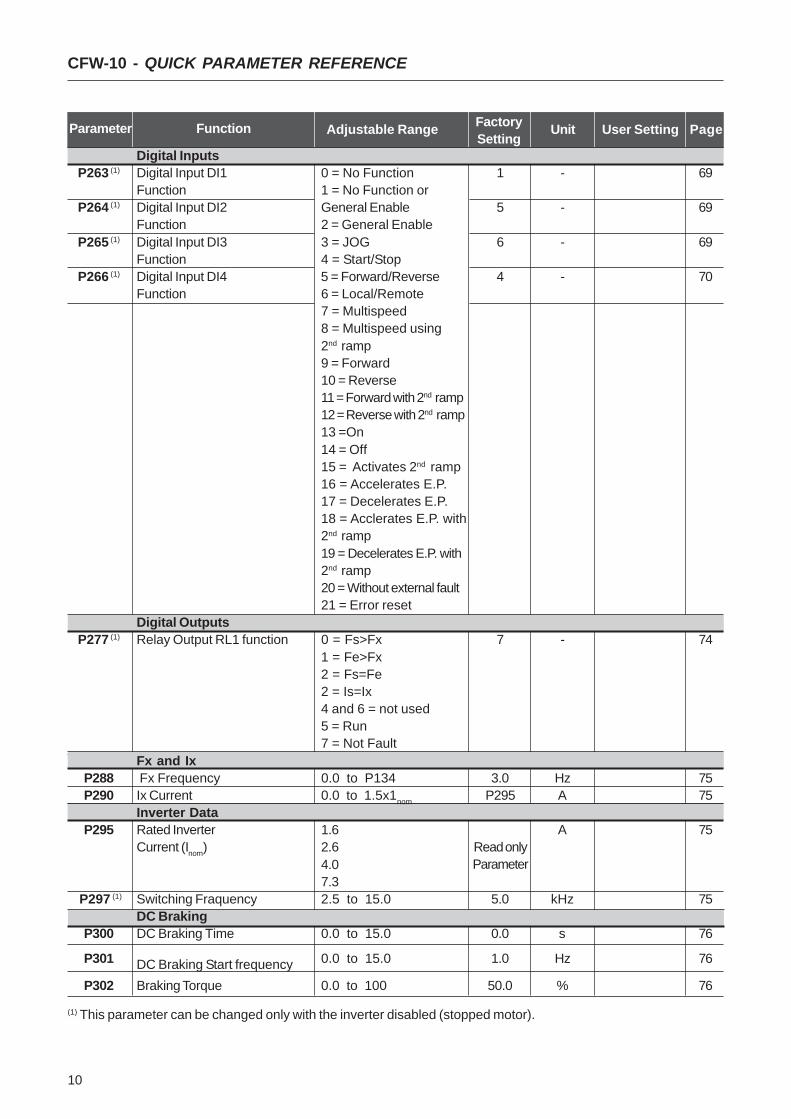
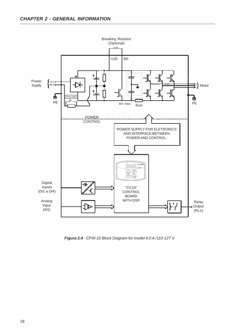
2.3 ABOUT THE CFW-10 The CFW-10 frequency inverter is fitted with the V/F (scalar)control method.The V/F (scalar) mode is recommended for more simpleapplications such as pump and fan drives. In these cases onecan reduce the motor and inverter losses by using the"Quadratic V/F" option, that results in energy saving.The V/F mode is also used when more than one motor shouldbe driven simultaneously by one inverter (multimotorapplication).Chapter 9 shows the different power lines and additionaltechnical informationThe block diagram below gives a general overview of theCFW-10.
Figure 2.1 - CFW-10 Block Diagram for models 1,6 - 2,6 - 4,0A / 200-240V
PowerSupply
L/L1
PE
Analog Input(AI1)
DigitalInputs
(DI1 to DI4)
POWERCONTROL
POWER SUPPLY ANDCONTROL/POWER INTERFACES
"CC10"CONTROL BOARD
WITH DSPRelayOutput(RL1)
MotorUVW
Rsh
NTC
RFI Filter
N/L2
16
CHAPTER 2 - GENERAL INFORMATION
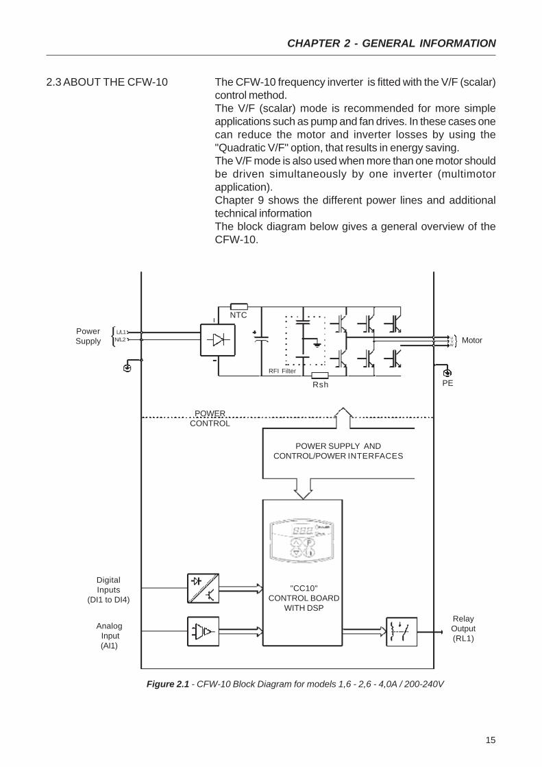
Figure 2.2 - CFW-10 Block Diagram for model 7,3 A/200-240 V
PowerSupply
L/L1
PE
AnalogInput(AI1)
DigitalInputs
(DI1 to DI4)
POWERCONTROL
POWER SUPPLY FOR ELETRONICSAND INTERFACE BETWEEN
POWER AND CONTROL.
"CC10"CONTROL
BOARDWITH DSP Relay
Output(RL1)
MotorUVW
Rsh
+UD
RFI Filter
N/L2
BR
Breaking Resistor(Optional)
Pre-Load

17
CHAPTER 2 - GENERAL INFORMATION
PowerSuplly
L/L1
AnalogInput(AI1)
DigitalInputs
(DI1 a DI4)
POWERCONTROL
POWER SUPPLY FOR ELETRONICSAND INTERFACE BETWEEN
POWER AND CONTROL.
"CC10"CONTROL
BOARDWITH DSP
RelayOutput(RL1)
MotorUVW
RshNTCPE PERFI Filter
N/L2
Figure 2.3 - CFW-10 Block Diagram for model 1,6A to 2,6 A/110-127 V
18
CHAPTER 2 - GENERAL INFORMATION
Figura 2.4 - CFW-10 Block Diagram for model 4,0 A /110-127 V
PowerSuplly
L/L1
AnalogInput(AI1)
DigitalInputs
(DI1 a DI4)
POWERCONTROL
POWER SUPPLY FOR ELETRONICSAND INTERFACE BETWEEN
POWER AND CONTROL.
"CC10"CONTROL
BOARDWITH DSP Relay
Output(RL1)
MotorUVW
RshPE PERFI Filter
N/L2
+UD BR
Breaking Resistor(Optional)
Pre-Load

19
CHAPTER 2 - GENERAL INFORMATION
2.4 CFW-10 IDENTIFICATION
Figure 2.5 - Description and Location of the Nameplate
SoftwareVersion
HardwareRevision
Rated Input Data(Voltage, Current, etc)
Manufacturing DateWEG Part NumberSerial Number
CFW-10 ModelRated Output Data
(Voltage, Frequency)
Lateral Nameplate CFW-10

20
CHAPTER 2 - GENERAL INFORMATION
HOW TO SPECIFY THE CFW-10 MODEL
CFW-10 0040 S 2024 P O 00 00 00 Z
SpecialSoftware00= none
SpecialHardware00= none
Rated OutputCurrent for
220 a 240V:0016=1.6A0026=2.6A0040=4.0A0073=7.3A
110 a 127V:0016=1.6A0026=2.6A0040=4.0A
Number ofphases ofthe powersupplys=singlephase
ManualLanguage:P= PortugueseE= EnglishS= Spanish
Powersupply:2024 =200 to 240V1112 =110 to 127V
Options:S= standardO=withoptions
WEGSeries 10FrequencyInverter
ControlBoard:00=standardcontrol
End code
NOTE!The Option field (S or O) defines if the CFW-10 is astandard version or if it will be equipped with any optionaldevices. If the standard version is required, the specificationcode ends here.The model number has always the letter Z at the end. Forexample:
CFW100040S2024ESZ = standard 4.0A CFW-10 inver-ter, single-phase at 200V to 240V input with manual inEnglish.
If the CFW-10 is equipped with any optional devices, youmust fill out all fields in the correct sequence up to the lastoptional device, the model number is completed with theletter Z.
The listing of the existing models (voltage/current) is shownin item 9.1.
The CFW-10 is supplied in cardboard boxes.There is a nameplate on the outside of the packing box that isidentical to that one on the CFW-10.Please check if the CFW-10 is the one you ordered.Check if the:
CFW-10 nameplate data matches with your purchase order.The equipment has not been damaged during transport.If any problem is detected, contact the carrier immedately.
If the CFW-10 is not installed immediately, store it in a cleanand dry room (storage temperatures between -25°C and60°C). Cover it to protect it against dust, dirt or othercontamination.
2.5 Receiving and Storing
21
CHAPTER 3
INSTALLATION AND CONNECTION
3.1 MECHANICALINSTALLATION
This chapter describes the procedures for the electrical andmechanical installation of the CFW-10.These guidelines and suggestions must be followed for properoperation of the CFW-10.
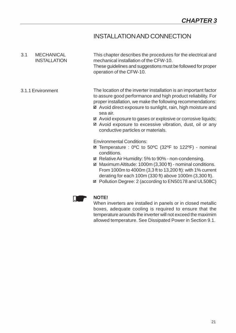
3.1.1 Environment The location of the inverter installation is an important factorto assure good performance and high product reliability. Forproper installation, we make the following recommendations:
Avoid direct exposure to sunlight, rain, high moisture andsea air.Avoid exposure to gases or explosive or corrosive liquids;Avoid exposure to excessive vibration, dust, oil or anyconductive particles or materials.
Environmental Conditions:Temperature : 0ºC to 50ºC (32ºF to 122ºF) - nominalconditions.Relative Air Humidity: 5% to 90% - non-condensing.Maximum Altitude: 1000m (3,300 ft) - nominal conditions.From 1000m to 4000m (3,3 ft to 13,200 ft): with 1% currentderating for each 100m (330 ft) above 1000m (3,300 ft).Pollution Degree: 2 (according to EN50178 and UL508C)
NOTE!When inverters are installed in panels or in closed metallicboxes, adequate cooling is required to ensure that thetemperature arounds the inverter will not exceed the maximimallowed temperature. See Dissipated Power in Section 9.1.

22
CHAPTER 3 - INSTALLATION AND CONNECTION
Table 3.1 - Recommended free spaces
Install the inverter in vertical position.Leave free space around the inverter as indicated in Table3.1.Do not install heat sensitive components immediately abovethe inverter.When inverters are installed top and bottom, maintain theminimum recommended distance A + B and deflect the hotair coming from the inverter below.Install the inverter on a flat surface.External dimensions and mounting holes are according toFig. 3.2.For CFW-10 installation procedures, see Fig. 3.3.Provide independent conduits for signal, control and powerconductors. (Refer to Electrical Installation). Separate themotor cables from the other cables.
CFW-10 Model1,6A / 200-240V2,6A / 200-240V4,0A / 200-240V7,3A / 200-240V1,6A / 110-127V2,6A / 110-127V4,0A / 110-127V
A B C
30 mm 1,18 in 50 mm 2 in 50 mm 2 in
3.1.2 Mounting Specification
Figure 3.1 - Free-Spaces for Cooling

23
CHAPTER 3 - INSTALLATION AND CONNECTION
Figure 3.2 - Dimensional Drawings of the CFW-10 - MEC 1 and 2
VIEW OF THEMOUNTING BASE
FRONTALVIEW
LATERAL VIEW
MEC 2
L
MEC 1

24
CHAPTER 3 - INSTALLATION AND CONNECTION
Model
1,6A / 200-240V
2,6A / 200-240V
4,0A / 200-240V
7,3A / 200-240V
1,6A / 110-127V
2,6A / 110-127V
4,0A / 110-127V
WidthL
mm(in)95
(3.74)95
(3.74)95
(3.74)115
(4.53)95
(3.74)95
(3.74)115
(4.53)
HeightH
mm(in)132
(5.20)132
(5.20)132
(5.20)161
(6.34)132
(5.20)132
(5.20)161
(6.34)
DepthP
mm(in)121
(4.76)121
(4.76)121
(4.76)122(4.8)121
(4.76)121
(4.76)122(4.8)
Amm(in)
85(3.35)
85(3.35)
85(3.35)105
(4.13)85
(3.35)85
(3.35)105
(4.13)
Bmm(in)
119.8(4.72)119.8(4.72)119.8(4.72)149
(5.83)119.8(4.72)119.8(4.72)149
(5.83)
Cmm(in)
5(0.2)
5(0.2)
5(0.2)
5(0.2)
5(0.2)
5(0.2)
5(0.2)
Dmm(in)
6.1(0.24)6.1
(0.24)6.1
(0.24)6
(0.24)6.1
(0.24)6.1
(0.24)6
(0.24)
MountingScrew
M4
M4
M4
M4
M4
M4
M4
Weightkg(lb)
0.9(1.98)
0.9(1.98)
0.9(1.98)
1.5(3.31)
0.9(1.98)
0.9(1.98)
1.5(3.31)
Degree ofProtection
IP20
IP20
IP20
IP20
IP20
IP20
IP20
Dimensions Fixing Base
Table 3.2 - Installation Data (dimensions in mm) - Refere to Section 9.1
Figure 3.3 - Mounting Procedures for the CFW-10
Air Flow
3.2 ELECTRICALINSTALLATION
3.2.1 Power / GroundingConnections
DANGER!Provide an AC input disconnecting switch to switch OFF thepower suplly from the inverter.This device shall disconnect the inverter from the AC inputsupply when required (e.g. during maintenances services)However it can not be used as an emergency stop device.

25
CHAPTER 3 - INSTALLATION AND CONNECTION
DANGER!Be sure the AC input power has been disconnected beforemaking any terminal connection.
DANGER!The information below will be a guide to achieve a properinstallation.Follow also all applicable local standards forelectrical installations.
ATENTION!Provide at least 0.25m (10in) spacing between the equipmentand sensitive wirings, inverter and motor cables . For instance:PLCs, temperature monitoring devices, thermocouples, etc.
a) Models 1,6A, 2,6A and 4,0A/200-240V and 1,6A and 2,6A/110-127V
Power Supply
L/L1
PE
PE UVW
Shielding
Q1
N/L2 U V W PE
N/L2
L/L1
26
CHAPTER 3 - INSTALLATION AND CONNECTION
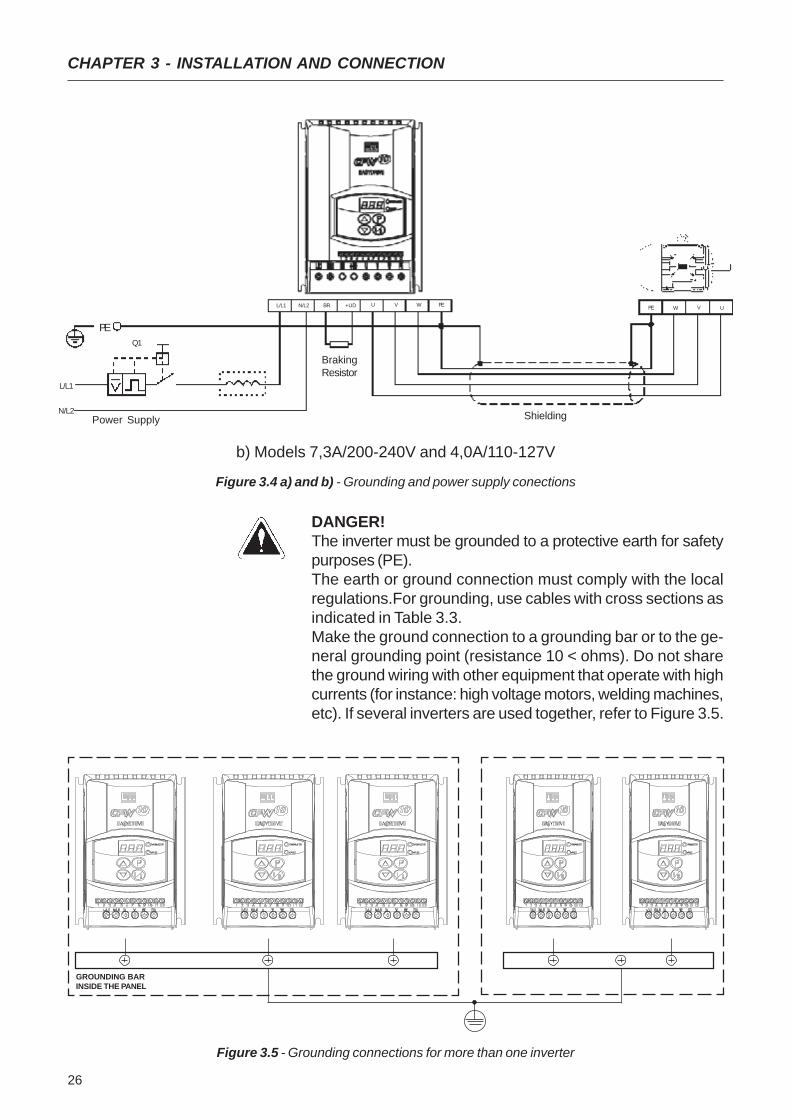
Figure 3.4 a) and b) - Grounding and power supply conections
Power Supply
L/L1
PE
PE UVW
Shielding
Q1
N/L2 U V W PE
N/L2
L/L1
b) Models 7,3A/200-240V and 4,0A/110-127V
+UDBR
BrakingResistor
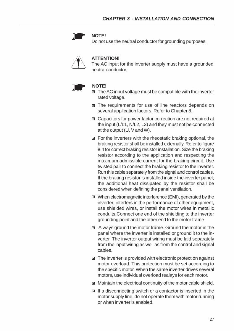
DANGER!The inverter must be grounded to a protective earth for safetypurposes (PE).The earth or ground connection must comply with the localregulations.For grounding, use cables with cross sections asindicated in Table 3.3.Make the ground connection to a grounding bar or to the ge-neral grounding point (resistance 10 < ohms). Do not sharethe ground wiring with other equipment that operate with highcurrents (for instance: high voltage motors, welding machines,etc). If several inverters are used together, refer to Figure 3.5.
Figure 3.5 - Grounding connections for more than one inverter
GROUNDING BARINSIDE THE PANEL
27
CHAPTER 3 - INSTALLATION AND CONNECTION
NOTE!Do not use the neutral conductor for grounding purposes.
ATTENTION!The AC input for the inverter supply must have a groundedneutral conductor.
NOTE!The AC input voltage must be compatible with the inverterrated voltage.The requirements for use of line reactors depends onseveral application factors. Refer to Chapter 8.
Capacitors for power factor correction are not required atthe input (L/L1, N/L2, L3) and they must not be connectedat the output (U, V and W).
For the inverters with the rheostatic braking optional, thebraking resistor shall be installed externally. Refer to figure8.4 for correct braking resistor installation. Size the brakingresistor according to the application and respecting themaximum admissible current for the braking circuit. Usetwisted pair to connect the braking resistor to the inverter.Run this cable separately from the signal and control cables.If the braking resistor is installed inside the inverter panel,the additional heat dissipated by the resistor shall beconsidered when defining the panel ventilation.When electromagnetic interference (EMI), generated by theinverter, interfers in the performance of other equipment,use shielded wires, or install the motor wires in metallicconduits.Connect one end of the shielding to the invertergrounding point and the other end to the motor frame.
Always ground the motor frame. Ground the motor in thepanel where the inverter is installed or ground it to the in-verter. The inverter output wiring must be laid separatelyfrom the input wiring as well as from the control and signalcables.
The inverter is provided with electronic protection againstmotor overload. This protection must be set according tothe specific motor. When the same inverter drives severalmotors, use individual overload realays for each motor.Maintain the electrical continuity of the motor cable shield.
If a disconnecting switch or a contactor is inserted in themotor supply line, do not operate them with motor runningor when inverter is enabled.
28
CHAPTER 3 - INSTALLATION AND CONNECTION
RatedInverterCurrent
[ A ]1,6 (200-240V)1,6 (110-127V)2,6 (200-240V)2,6 (110-127V)4,0 (200-240V)4,0 (110-127V)7,3 (200-240V)
MotorWiring
mm2 AWG
1,5 141,5 141,5 141,5 141,5 141,5 142,5 12
GroundingWiring
mm2 AWG
2,5 122,5 122,5 122,5 122,5 124,0 104,0 10
Current
6101015152020
WEGModel
MPW25-6,3MPW25-10MPW25-10MPW25-16MPW25-16MPW25-20MPW25-20
Circuit-BreakerPowerCables
mm2 AWG
1,5 141,5 141,5 142,5 121,5 142,5 122,5 12
MaximumCables
mm2 AWG
2,5 122,5 122,5 122,5 122,5 124,0 104,0 10
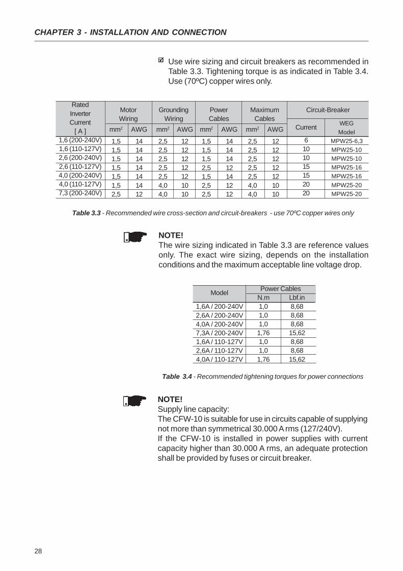
Use wire sizing and circuit breakers as recommended inTable 3.3. Tightening torque is as indicated in Table 3.4.Use (70ºC) copper wires only.
Table 3.3 - Recommended wire cross-section and circuit-breakers - use 70ºC copper wires only
NOTE!Supply line capacity:The CFW-10 is suitable for use in circuits capable of supplyingnot more than symmetrical 30.000 A rms (127/240V).If the CFW-10 is installed in power supplies with currentcapacity higher than 30.000 A rms, an adequate protectionshall be provided by fuses or circuit breaker.
NOTE!The wire sizing indicated in Table 3.3 are reference valuesonly. The exact wire sizing, depends on the installationconditions and the maximum acceptable line voltage drop.
Table 3.4 - Recommended tightening torques for power connections
Model
1,6A / 200-240V2,6A / 200-240V4,0A / 200-240V7,3A / 200-240V1,6A / 110-127V2,6A / 110-127V4,0A / 110-127V
Power CablesN.m Lbf.in1,0 8,681,0 8,681,0 8,681,76 15,621,0 8,681,0 8,681,76 15,62

29
CHAPTER 3 - INSTALLATION AND CONNECTION
3.2.2 Power Terminals Description of the Power Terminals:
L/L1, N/L2 : AC supply line
U, V and W: Motor connection.
PE: grounding connection.
BR: Connection terminal for the braking resistor. Notavailable for 1,6A, 2,6A and 4A/200-240V and 1,6A and2,6A/110-127V models.
+UD: Positive connection terminal (DC Link). This terminalis used to connect the braking resistor (connect also theBR terminal). Not available for 1,6A, 2,6A and4,0A/200-240V and 1,6A and 2,6A/110-127V models.
a) models 1,6A, 2,6A and 4,0A/200-240V and 1,6A and2,6A/110-127V
Figura 3.6 - a) and b) CFW-10 Power Terminals
b) models 7,3A/200-240V and 4,0A/110-127V

30
CHAPTER 3 - INSTALLATION AND CONNECTION
3.2.3 Location of the Power,Grounding and ControlConnections
Figure 3.7 - Location of the Power and Control Connections
3.2.4 Signal and ControlConnections
The signal (analog input) and control connections (digital inputsand relay output) are made on the XC1 connector of controlboard (see location in Figure 3.7).
Control XC1
Power
Figure 3.8 - Description of the XC1 terminal of the control board
XC1 Terminal
1 DI1
2 DI2
3 DI3
4 DI4
5 GND
6 AI1
7 GND8 AI1
9 +10V
10 NC
11 Common12 NO
DescriptionFactory Default Function
Digital Input 1General Enable (remote mode)Digital Input 2FWD / REV (remote mode)Digital Input 3Local/RemoteDigital Input 4Start / Stop (remote mode)
0V Reference
Analog Input 1Freq. Reference (remote mode)
0V ReferenceAnalog Input (voltage)Frequency Reference (remote)
Potentiometer referenceRelay NC contactNo FaultRelay Output - common pointRelay NO contactNo Fault
Specifications
4 isolated digital inputsMinimum High Level: 10V dcMaximum High Level: 30V dcMaximum Low Level:3V dcInput current: -11mA @ 0VMax. input current: -20 mA
Not interconnected with PE
Current: (0 to 20)mA or (4 to 20)mAImpedance: 500Ω. Resolution: 7bits.
Not interconnected with PE
Voltage: 0 to 10V dc.Impedance: 100kΩ. Resolution: 7bits.Max. input voltage: 30V dc+10V dc, ± 5%, capacity: 2mA
(0 to
20)
mA
(4 to
20)
mA
Relay
CW
CCW
≥5 k
Ω
10 12
11
Contact capacity:0,5A / 250V ac
(+)
(-)

31
CHAPTER 3 - INSTALLATION AND CONNECTION
NOTE!If the input current from 4 mA to 20 mA is used as standard,do not forget to set the Parameter P235 which defines thesignal type at AI1.
During the signal and control wire installation note thefollowing:
1) Cable cross section: (0.5 to 1.5) mm² / (20 to 14) AWG.
2) Max. Torque: 0.50 N.m (4.50 lbf.in).
3) XC1 wiring must be realized with shielded cables and tobe installed separately at a distance of 10cm (3.94 in) eachother for lengths up to 100m (328 ft) and at distance of25cm (9.8 in) each other for lengths over 100m (328 ft). Ifthe crossing of these cables is unavoidable, install themperpendicular, maintaining a mimimum separation distanceof 5cm (2in) at the crossing point.
Figure 3.9 - Shield connection
Connect to earth
Do notground
Inverterside
Insulate withtape
4) For wiring distances longer than 50 m ( 150 ft), the use ofgalvanic isolators is required for the XC1:6 to 9 analogsignals.
5) Relays, contactors, solenoids or eletromagnetic brakingcoils installed near inverters can eventually generateinterferences in the control circuit. To eliminate thisinterference, connect RC suppressor in parallel with thecoils of AC relays. Connect free-wheeling diode in case ofDC relays.
Connect the shield as shown below:

32
CHAPTER 3 - INSTALLATION AND CONNECTION
3.2.5 Typical TerminalConnections
Connection 1
With the factory default programming, it is posible tooperate the inverter in local mode with the minimumconnections shown in Figure 3.4 (Power) and without controlconnections. This operation mode is recommended for userswho are operating the inverter for the first time as initial learningabout equipment.Note that any connection is needed on controlterminal.
For start-up according to this operation mode, refer to Chapter 4.
Connection 2
Command enabling via terminals.
6) When analog reference (AI1) is used and thefrequency oscillates (problem caused byelectromagnetic interference) connect XC1:7 to theinverter grounding bar.
S1: FWD / REV
S2: Loca/Remote
S3: Start / Stop
R1: Potentiometer for Speed Setting
Figure 3.10 – Wiring for Connection 2
DI1
- N
o Fu
nctio
n (H
MI)
orG
ener
al E
nabl
ing
(Ter
min
als)
DI2
- FW
D /
RE
V
DI3
- L
ocal
/Rem
ote
GN
D
AI1
(0/4
to 2
0mA
)
GN
D
AI1
(0 to
10V
dc)
+10V
NC
Com
mon
NO
DI4
- N
o Fu
nctio
n (H
MI)
orSt
art /
Sto
p (T
erm
inal
s)
S1
≥≥≥≥≥
1 2 3 4 5 6 7 8 9 10 11 12
5K
NOTE!The frequency reference can be sent via AI1 analog input(as shown in figure above), via keypad HMI-CFW10, or viaany other source (see description of Parameters P221 andP222).
S2 S3
33
CHAPTER 3 - INSTALLATION AND CONNECTION
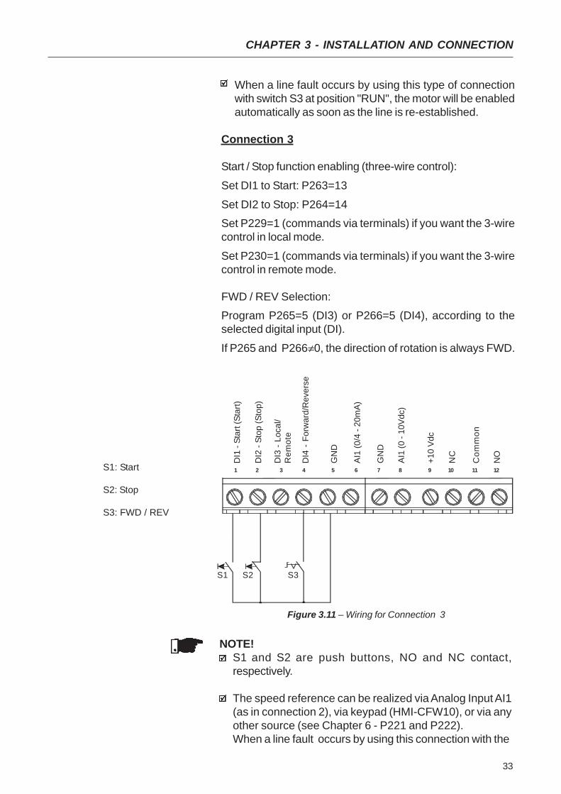
Figure 3.11 – Wiring for Connection 3
NOTE!S1 and S2 are push buttons, NO and NC contact,respectively.
The speed reference can be realized via Analog Input AI1(as in connection 2), via keypad (HMI-CFW10), or via anyother source (see Chapter 6 - P221 and P222).When a line fault occurs by using this connection with the
S1: Start
S2: Stop
S3: FWD / REV
DI1
- St
art (
Star
t)
DI2
- St
op (S
top)
DI3
- Lo
cal/
Rem
ote
GN
D
AI1
(0/4
- 20
mA
)
GN
D
AI1
(0 -
10V
dc)
+10
Vdc
NC
Com
mon
NO
DI4
- F
orw
ard/
Rev
erse
S3S2
1 2 3 4 5 6 7 8 9 10 11 12
S1
When a line fault occurs by using this type of connectionwith switch S3 at position "RUN", the motor will be enabledautomatically as soon as the line is re-established.
Connection 3
Start / Stop function enabling (three-wire control):
Set DI1 to Start: P263=13
Set DI2 to Stop: P264=14Set P229=1 (commands via terminals) if you want the 3-wirecontrol in local mode.
Set P230=1 (commands via terminals) if you want the 3-wirecontrol in remote mode.
FWD / REV Selection:Program P265=5 (DI3) or P266=5 (DI4), according to theselected digital input (DI).
If P265 and P266≠0, the direction of rotation is always FWD.

34
CHAPTER 3 - INSTALLATION AND CONNECTION
motor running and the S1 and S2 switches are in originalposition (S1 openned and S2 closed), the inverter will notbe enabled automatically as soon as the line is re-restablished.The Start/Stop function is described in Chapter 6.
Connection 4
Enabling of the FWD / REV function:
Set DI1 to Forward Run : P263 = 9
Set DI2 to Reverse Run: P264 = 10Make sure the inverter commands are via terminals, i.e., setP229=1 to local mode.
NOTE!The speed reference can be realized via Analog Input AI1(as in connection 2), via keypad (HMI), or via any othersource (see description of parameters P221 and P222).When a line fault occurs in this connection mode with switchS1 or switch S2 is closed, the motor will be enabledautomatically as soon as the line is re-restablished.
3.3 European EMCDirective -Requirements forConforming Installations
The CFW-10 inverter series was designed considering allsafety and EMC (ElectroMagnetic Compatibility) aspects.The CFW-10 units do not have an intrinsic function untilconnected with other components (e. g. a motor). Therefore,the basic product is not CE marked for compliance with the
Figure 3.12 – Wiring for Connection 4
DI4
- N
o Fu
nctio
n / R
amp
Ena
blin
g
S1 open: StopS1 closed: Forward RunS2 open: StopS2 closed: Reverse Run
DI1
- Fo
rwar
d R
un
DI2
- R
ever
se R
un
DI3
- L
ocal
/Rem
ote
GN
D
AI1
(0/4
- 20
mA
)
GN
D
AI1
(0 -
10V
dc)
+10V
dc
NC
Com
mon
NO
S2S1
1 2 3 4 5 6 7 8 9 10 11 12
35
CHAPTER 3 - INSTALLATION AND CONNECTION
EMC Directive. The end user takes personal responsibilityfor the EMC compliance of the whole installation. However,when installed according to the recommendations describedin the product manual and including the recommended filtersand EMC measures the CFW-10 fulfill all requirements of theEMC Directive (89/336/EEC) as defined by the EN61800-3"EMC Product Standard for Adjustable Speed ElectricalPower Drive Systems - specific standard for variable speeddrives.The conformity of the complete CFW-10 series is based ontests performed on sample models. A Technical ConstructionFile (TCF) was prepared, checked and approved by aCompetent Body.
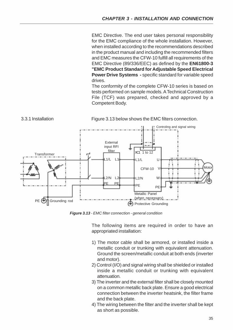
3.3.1 Installation Figure 3.13 below shows the EMC filters connection.
Figure 3.13 - EMC filter connection - general condition
Transformer
Grounding rod
Metallic Panel(when necessary)Protective Grounding
Motor
PE
CFW-10
L2/N
L1/L
PE
PE
XC1 1 to 12
U
Controling and signal wiring
V
W
PE
L1/L
L2/NL2
L1
PE
Externalinput RFI
filter
The following items are required in order to have anappropriated installation:
1) The motor cable shall be armored, or installed inside ametallic conduit or trunking with equivalent attenuation.Ground the screen/metallic conduit at both ends (inverterand motor).
2) Control (I/O) and signal wiring shall be shielded or installedinside a metallic conduit or trunking with equivalentattenuation.
3) The inverter and the external filter shall be closely mountedon a common metallic back plate. Ensure a good electricalconnection between the inverter heatsink, the filter frameand the back plate.
4) The wiring between the filter and the inverter shall be keptas short as possible.
36
CHAPTER 3 - INSTALLATION AND CONNECTION
5) The cable shield (motor and control) shall be solidlyconnected to the common back plate, using metallicbrackets.
6) Grounding shall be performed as recommended in thisuser’s guide.
7) Use short and thick cables to ground the external filter orinverter. When an external filter is used, ground only the filter(input) - the inverter ground connection is performed throughthe metallic back plate.
8) Ground the back plate using a braid, as short as possible.Flat conductors (e.g. braids or brackets) have lowerimpedance at high frequencies.
9) Use cable glands whenever possible.
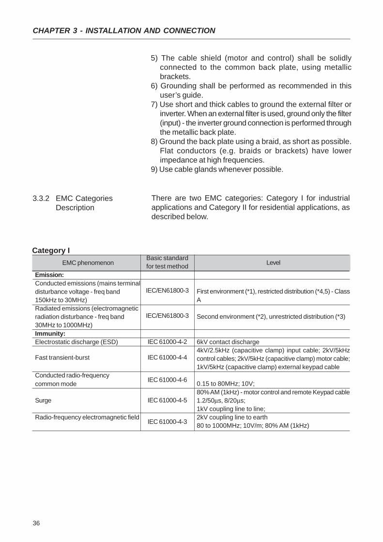
3.3.2 EMC CategoriesDescription
There are two EMC categories: Category I for industrialapplications and Category II for residential applications, asdescribed below.
EMC phenomenon
Emission:Conducted emissions (mains terminaldisturbance voltage - freq band150kHz to 30MHz)Radiated emissions (electromagneticradiation disturbance - freq band30MHz to 1000MHz)Immunity:Electrostatic discharge (ESD)
Fast transient-burst
Conducted radio-frequencycommon mode
Surge
Radio-frequency electromagnetic field
Basic standardfor test method
IEC/EN61800-3
IEC/EN61800-3
IEC 61000-4-2
IEC 61000-4-4
IEC 61000-4-6
IEC 61000-4-5
IEC 61000-4-3
Level
First environment (*1), restricted distribution (*4,5) - ClassA
Second environment (*2), unrestricted distribution (*3)
6kV contact discharge4kV/2.5kHz (capacitive clamp) input cable; 2kV/5kHzcontrol cables; 2kV/5kHz (capacitive clamp) motor cable;1kV/5kHz (capacitive clamp) external keypad cable
0.15 to 80MHz; 10V;80% AM (1kHz) - motor control and remote Keypad cable1.2/50μs, 8/20μs;1kV coupling line to line;2kV coupling line to earth80 to 1000MHz; 10V/m; 80% AM (1kHz)
Category I
37
CHAPTER 3 - INSTALLATION AND CONNECTION
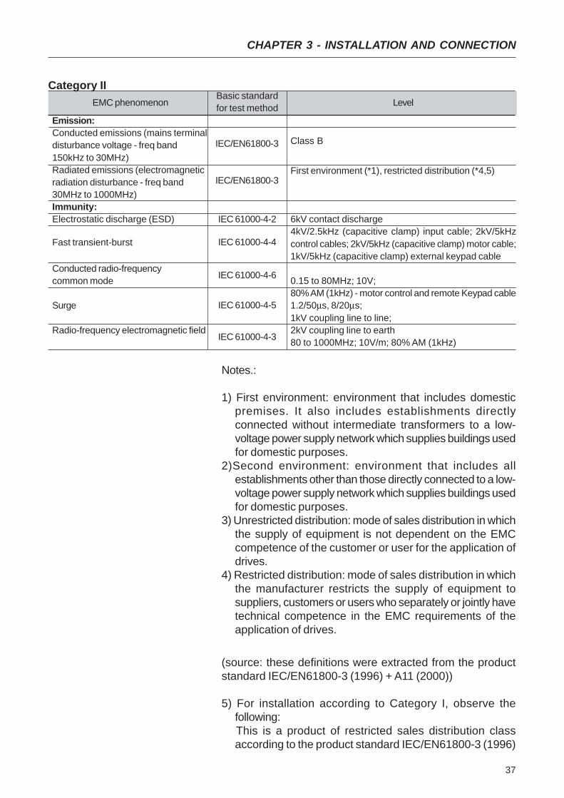
EMC phenomenon
Emission:Conducted emissions (mains terminaldisturbance voltage - freq band150kHz to 30MHz)Radiated emissions (electromagneticradiation disturbance - freq band30MHz to 1000MHz)Immunity:Electrostatic discharge (ESD)
Fast transient-burst
Conducted radio-frequencycommon mode
Surge
Radio-frequency electromagnetic field
Basic standardfor test method
IEC/EN61800-3
IEC/EN61800-3
IEC 61000-4-2
IEC 61000-4-4
IEC 61000-4-6
IEC 61000-4-5
IEC 61000-4-3
Level
Class B
First environment (*1), restricted distribution (*4,5)
6kV contact discharge4kV/2.5kHz (capacitive clamp) input cable; 2kV/5kHzcontrol cables; 2kV/5kHz (capacitive clamp) motor cable;1kV/5kHz (capacitive clamp) external keypad cable
0.15 to 80MHz; 10V;80% AM (1kHz) - motor control and remote Keypad cable1.2/50μs, 8/20μs;1kV coupling line to line;2kV coupling line to earth80 to 1000MHz; 10V/m; 80% AM (1kHz)
Category II
Notes.:
1) First environment: environment that includes domesticpremises. It also includes establishments directlyconnected without intermediate transformers to a low-voltage power supply network which supplies buildings usedfor domestic purposes.
2)Second environment: environment that includes allestablishments other than those directly connected to a low-voltage power supply network which supplies buildings usedfor domestic purposes.
3) Unrestricted distribution: mode of sales distribution in whichthe supply of equipment is not dependent on the EMCcompetence of the customer or user for the application ofdrives.
4) Restricted distribution: mode of sales distribution in whichthe manufacturer restricts the supply of equipment tosuppliers, customers or users who separately or jointly havetechnical competence in the EMC requirements of theapplication of drives.
(source: these definitions were extracted from the productstandard IEC/EN61800-3 (1996) + A11 (2000))
5) For installation according to Category I, observe thefollowing:
This is a product of restricted sales distribution classaccording to the product standard IEC/EN61800-3 (1996)

38
CHAPTER 3 - INSTALLATION AND CONNECTION
3.3.3 Inverter and Filters
+ A11 (2000). In a domestic environment this product maycause radio interference in which case the user may berequired to take adequate measures.
6) The harmonic current emissions defined by the standardsIEC/EN61000-3-2 and EN61000-3-2 / A14 do not applybecause the CFW-10 inverter series are intended forprofessional applications.
Table 3.5 shows the inverter models, its respective EMC filterand the EMC category classification. Refer to section 3.2.2for EMC category description and to section 3.3.4 for filtercharacteristics.
Inverter Model
1,6A / 200-240V
2,6A / 200-240V
4,0A / 200-240V
1,6A / 110-127V
2,6A / 110-127V
Input RFIFilter
Footprint / booksizemodel:
B84142A0012R212(EPCOS)
Standard Model:B84142-A20-R
(EPCOS)
EMC Class
Category I (industrial environment) -Class A1. Maximum motor cable lengthis 30 meters.
Category I (industrial environment) -Class A2. Maximum motor cable lengthis 50 meters.
Category II (residential environment)Class A1. Maximum motor cable lengthis 5 meters.
Table 3.5 - List of frequency inverter models, EMC filters and EMC categories
Note: Maximum switching frequency is 5kHz.

39
CHAPTER 3 - INSTALLATION AND CONNECTION
3.3.4 Characteristicsof the EMC Filters
Footprint / booksize Model B84142A0012R212 (EPCOS)Supply voltage: 250V, 50/60HzCurrent: 12AWeight: 0,95Kg
Figure 3.14 – Drawing of the footprint / bookside filter B84142A0012R212 (EPCOS)
Terminals 2,5 mm2
Tightgning torque of screwmax. 0,5 Nm
3 x litzwire 2,5 mm2
3 x wire and sleeve DIN 46228-A2, 5-10

40
CHAPTER 3 - INSTALLATION AND CONNECTION
Standard Model: B84142 - A20-RSupply voltage: 250V, 50/60HzCurrent: 20AWeight: 1 kg
Figure 3.15 – Drawing of the Standard Filter: B84142-A20-R (EPCOS)
Terminais Terminais

41
CHAPTER 4
4.1 PRE-POWERCHECKS
This Chapter provides the following information:how to check and prepare the inverter before power-up;how to power-up and check for proper operation;how to operate the inverter when it is installed according tothe typical connections (refer to Section 3.2 - ElectricalInstallation).
The inverter shall be installed according to Chpater 3 -Installation and Connection. If the drive project is different fromthe typical suggested connections, follow the proceduresbelow.
DANGER!Alaways disconnect the AC input power before making anyconnections.
1) Check all connectionsCheck if the power, grounding and control connections arecorrect and well tightened.
2) Check the motorCheck all motor connections and verify if its voltage, currentand frequency match the inverter specifications.
3) Uncouple the load from the motorIf the motor can not be uncoupled, make sure that thedirection of rotation (FWD/REV) can not cause damage tothe machine.
4.2 INITIAL POWER-UP After the inverter has been checked, AC power can be applied:
1) Check the power supplyMeasure the line voltage and check if it is within thespecified range (rated voltage: - 15% / + 10%).
2) Power-up the AC inputClose the input circuit breaker.
3) Check if the power-up has been succesfulThe keypad display will show:
While the red LED (Parameter) is ON, the green LED (value)remains OFF. Inverter runs some self-diagnosis routines. If noproblems are found, the display shows:
START-UP
This means that the inverter is ready (rdy = ready) to beoperated.
42
CHAPTER 4 - START-UP
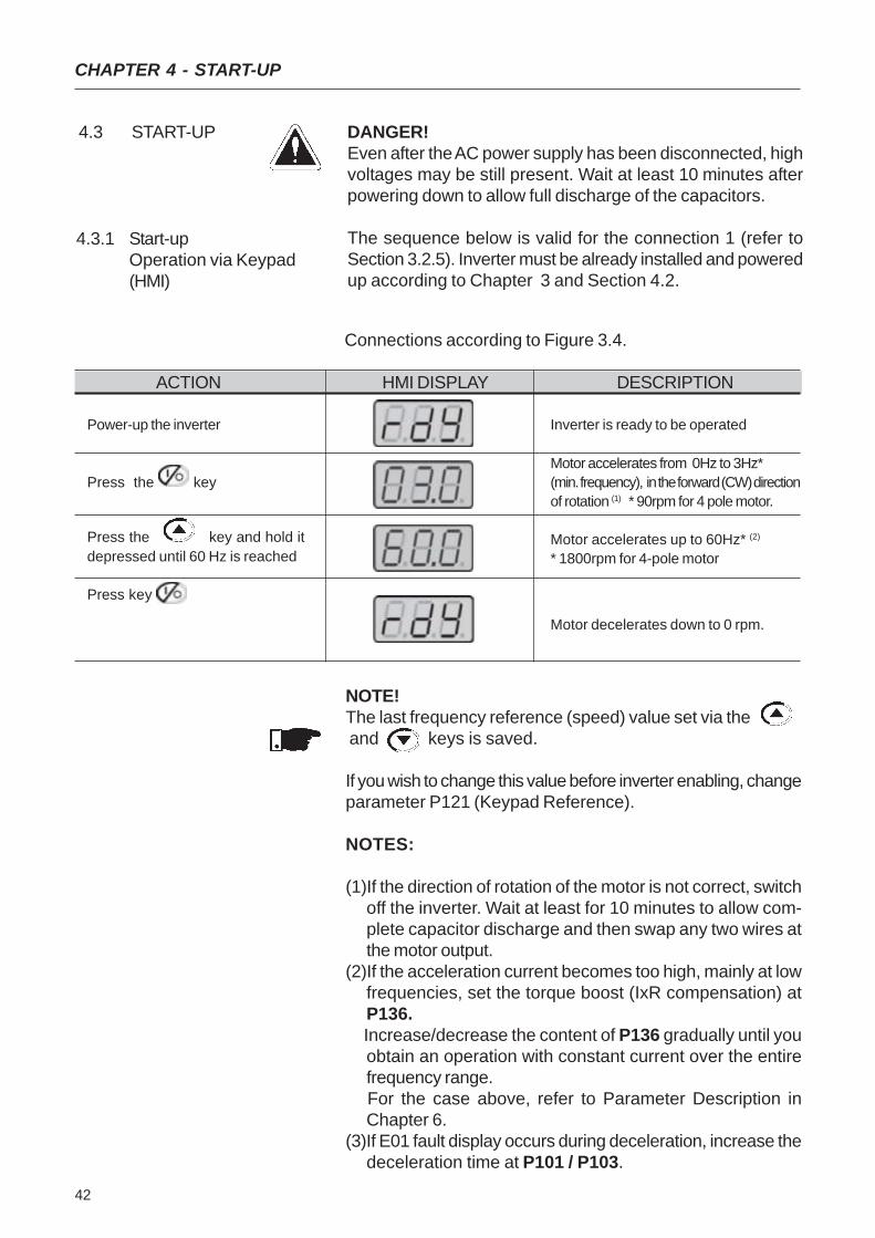
4.3 START-UP DANGER!Even after the AC power supply has been disconnected, highvoltages may be still present. Wait at least 10 minutes afterpowering down to allow full discharge of the capacitors.
The sequence below is valid for the connection 1 (refer toSection 3.2.5). Inverter must be already installed and poweredup according to Chapter 3 and Section 4.2.
4.3.1 Start-upOperation via Keypad(HMI)
Connections according to Figure 3.4.
NOTE!The last frequency reference (speed) value set via the and keys is saved.
If you wish to change this value before inverter enabling, changeparameter P121 (Keypad Reference).
NOTES:
(1)If the direction of rotation of the motor is not correct, switchoff the inverter. Wait at least for 10 minutes to allow com-plete capacitor discharge and then swap any two wires atthe motor output.
(2)If the acceleration current becomes too high, mainly at lowfrequencies, set the torque boost (IxR compensation) atP136.
Increase/decrease the content of P136 gradually until youobtain an operation with constant current over the entirefrequency range.
For the case above, refer to Parameter Description inChapter 6.
(3)If E01 fault display occurs during deceleration, increase thedeceleration time at P101 / P103.
ACTION HMI DISPLAY DESCRIPTION
Power-up the inverter
Press the key
Press the key and hold itdepressed until 60 Hz is reached
Press key
Inverter is ready to be operated
Motor accelerates from 0Hz to 3Hz*(min. frequency), in the forward (CW) directionof rotation (1) * 90rpm for 4 pole motor.
Motor accelerates up to 60Hz* (2)
* 1800rpm for 4-pole motor
Motor decelerates down to 0 rpm.
43
CHAPTER 4 - START-UP
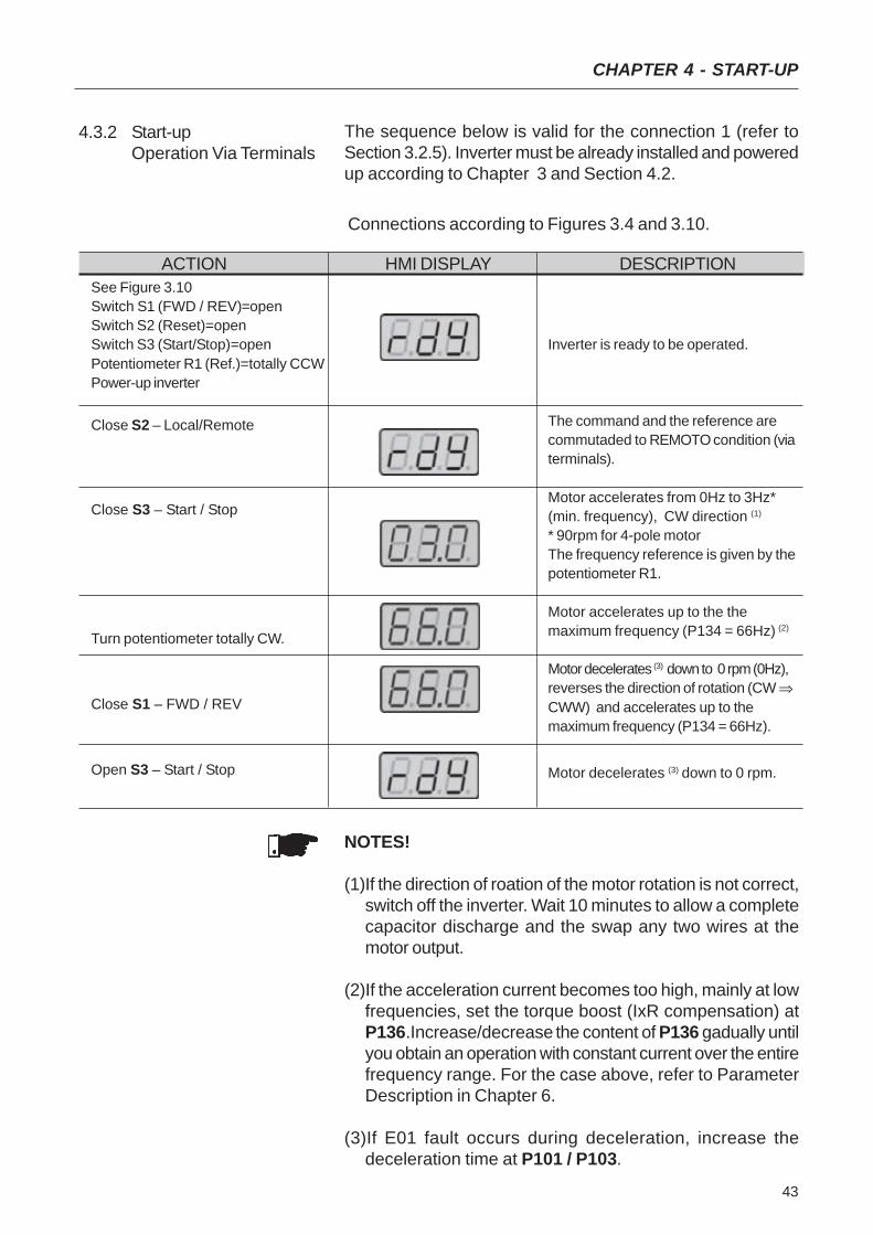
4.3.2 Start-upOperation Via Terminals
Connections according to Figures 3.4 and 3.10.
NOTES!
(1)If the direction of roation of the motor rotation is not correct,switch off the inverter. Wait 10 minutes to allow a completecapacitor discharge and the swap any two wires at themotor output.
(2)If the acceleration current becomes too high, mainly at lowfrequencies, set the torque boost (IxR compensation) atP136.Increase/decrease the content of P136 gadually untilyou obtain an operation with constant current over the entirefrequency range. For the case above, refer to ParameterDescription in Chapter 6.
(3)If E01 fault occurs during deceleration, increase thedeceleration time at P101 / P103.
The sequence below is valid for the connection 1 (refer toSection 3.2.5). Inverter must be already installed and poweredup according to Chapter 3 and Section 4.2.
ACTION HMI DISPLAY DESCRIPTIONSee Figure 3.10Switch S1 (FWD / REV)=openSwitch S2 (Reset)=openSwitch S3 (Start/Stop)=openPotentiometer R1 (Ref.)=totally CCWPower-up inverter
Close S2 – Local/Remote
Close S3 – Start / Stop
Turn potentiometer totally CW.
Close S1 – FWD / REV
Open S3 – Start / Stop
Inverter is ready to be operated.
The command and the reference arecommutaded to REMOTO condition (viaterminals).
Motor accelerates from 0Hz to 3Hz*(min. frequency), CW direction (1)
* 90rpm for 4-pole motorThe frequency reference is given by thepotentiometer R1.
Motor accelerates up to the themaximum frequency (P134 = 66Hz) (2)
Motor decelerates (3) down to 0 rpm (0Hz),reverses the direction of rotation (CW ⇒CWW) and accelerates up to themaximum frequency (P134 = 66Hz).
Motor decelerates (3) down to 0 rpm.

44
CHAPTER 5
KEYPAD (HMI) OPERATION
This chapter describes the CFW-10 operation via Human-Machine Interface (HMI), providing the following information:
general keypad description (HM)I;use of the keypad (HMI);parameter programming;description of the status indicators.
5.1 KEYPAD (HMI)DESCRIPTION
The standard CFW-10 keypad has a LED display with 3 digitsof 7 segments, 2 status LEDs and 4 keys. Figure 5.1 showsthe front view of the keypad and indicates the position of theDisplay and the status LEDs.
Functions of the LED Display:The Led Display shows the fault and status messages (seeQuick Parameter Reference, Fault and Status), the parameternumber and its value.
Functions of the LED´s “Parameter” and “Value”:
Inverter indicates the parameter number:Green Led OFF and red Led ON.
Inverter indicates the parameter content:Green Led ON and red Led OFF.
LED DisplayLED "Parameter"
LED "Value"
Figure 5.1 - CFW-10 keypad (HMI)
Basic Functions of the Keys:
Enables/disables the inverter via acceleration/decelerationramp (run/stop). Resets the inverter after a fault trip.
Selects (commutates) the display between parametyernumber/value (position/content).

45
CHAPTER 5 - KEYPAD (HMI) OPERATION
Increases the frequency, the parameter number or theparameter value.Decreases the frequency, the parameter number or theparameter value.
The Keypad (HMI) is a simple interface that allows inverteroperation/programming. This interface has the followingfunctions:
indication of the inverter status and operation variables;
fault indication and diagnostics;viewing and programming parameters;
inverter operation (key ) andspeed reference setting (keys and ).
5.2 USE OF THE KEYPADHMI
5.2.1 Keypad (HMI)Operation
All functions relating to the CFW-10 operation (Start/Stop,Direction of Rotation, JOG, Increment/Decrement of the Speed(Frequency) Reference, and selection of LOCAL/REMOTEmode) can be performed through the HMI selection. For factorydefault programming of the inverter, all keypad keys areenabled. These functions can be carried out through digitaland analog inputs. Thus you must program the parametersrelated to these corresponding inputs.
NOTE!The command key will be enabled only when:
P229=0 for LOCAL Mode operationP230=0 for REMOTE Mode operation
See below the keypad functions description:
When pressed, motor accelerates according to accelerationramp up to the speed (frequency) reference. The function issimilar to that performed through digital input START/STOP,when it is closed (enabled) and maintained enabled.When pressed again, inverter is disabled via ramp (motoraccelerates according to acceleration ramp and stops. Thefunction is similar to that performed through digital inputSTART/STOP, when it is opened (disabled) and maintaineddisabled.
Motor speed (frequency) setting: these keys are enabled forspeed setting only when:
the speed reference source is the keypad (P221 = 0 forLOCAL Mode and/or P222 = 0 for REMOTE Mode);the following parameter content is displayed: P002, P005or P121.
and
46
CHAPTER 5 - KEYPAD (HMI) OPERATION
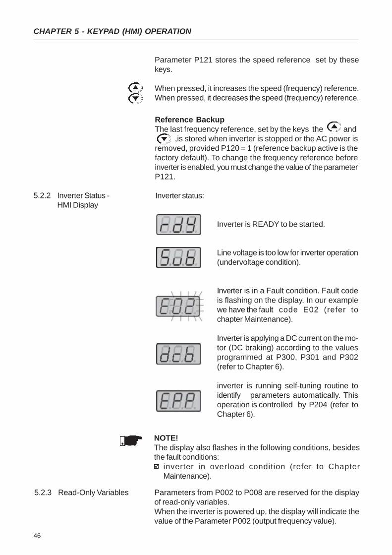
Inverter status:
Inverter is READY to be started.
Line voltage is too low for inverter operation(undervoltage condition).
Inverter is in a Fault condition. Fault codeis flashing on the display. In our examplewe have the fault code E02 (refer tochapter Maintenance).
Inverter is applying a DC current on the mo-tor (DC braking) according to the valuesprogrammed at P300, P301 and P302(refer to Chapter 6).
inverter is running self-tuning routine toidentify parameters automatically. Thisoperation is controlled by P204 (refer toChapter 6).
5.2.2 Inverter Status -HMI Display
NOTE!The display also flashes in the following conditions, besidesthe fault conditions:
inverter in overload condition (refer to ChapterMaintenance).
Reference BackupThe last frequency reference, set by the keys the and ,is stored when inverter is stopped or the AC power isremoved, provided P120 = 1 (reference backup active is thefactory default). To change the frequency reference beforeinverter is enabled, you must change the value of the parameterP121.
5.2.3 Read-Only Variables Parameters from P002 to P008 are reserved for the displayof read-only variables.When the inverter is powered up, the display will indicate thevalue of the Parameter P002 (output frequency value).
Parameter P121 stores the speed reference set by thesekeys.
When pressed, it increases the speed (frequency) reference.When pressed, it decreases the speed (frequency) reference.
47
CHAPTER 5 - KEYPAD (HMI) OPERATION
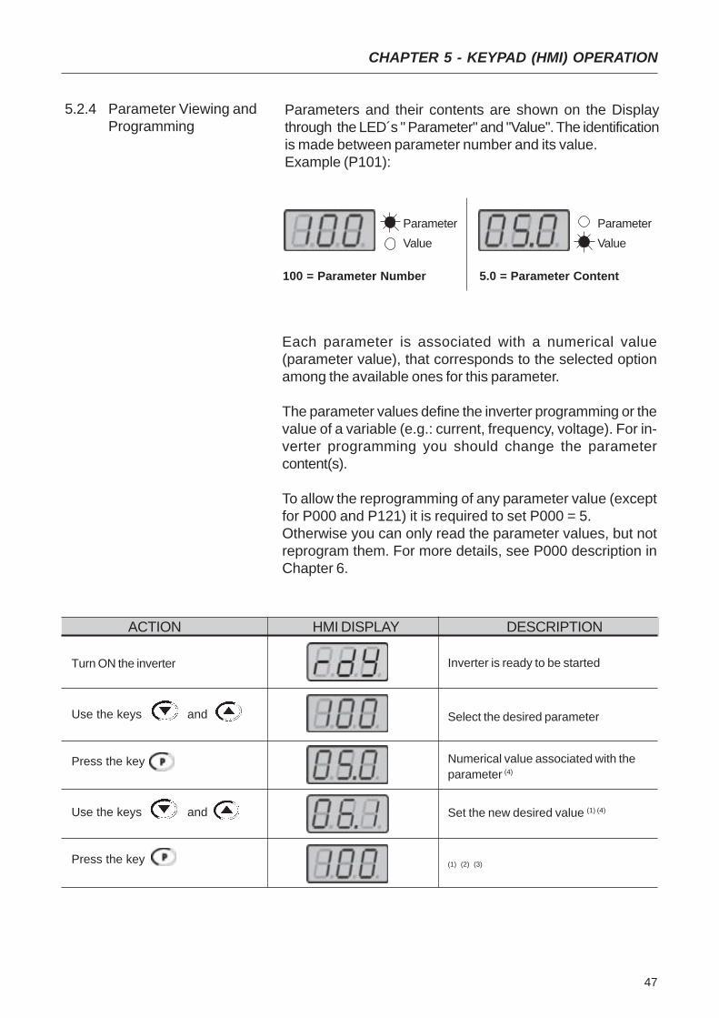
5.2.4 Parameter Viewing andProgramming
Parameters and their contents are shown on the Displaythrough the LED´s " Parameter" and "Value". The identificationis made between parameter number and its value.Example (P101):
Each parameter is associated with a numerical value(parameter value), that corresponds to the selected optionamong the available ones for this parameter.
The parameter values define the inverter programming or thevalue of a variable (e.g.: current, frequency, voltage). For in-verter programming you should change the parametercontent(s).
To allow the reprogramming of any parameter value (exceptfor P000 and P121) it is required to set P000 = 5.Otherwise you can only read the parameter values, but notreprogram them. For more details, see P000 description inChapter 6.
ParameterValue
100 = Parameter Number
ParameterValue
5.0 = Parameter Content
ACTION HMI DISPLAY DESCRIPTION
Turn ON the inverter
Use the keys and
Press the key
Use the keys and
Press the key
Inverter is ready to be started
Select the desired parameter
Numerical value associated with theparameter (4)
Set the new desired value (1) (4)
(1) (2) (3)

48
CHAPTER 5 - KEYPAD (HMI) OPERATION
NOTE!(1)For parameters that can be changed with the running mo-
tor , the inverter will use the new value immediately after ithas been set. For parameters that can be changed onlywith stopped motor , the inverter will use this new value onlyafter the key is pressed.
(2)By pressing the key after the reprogramming, the newprogrammed value will be saved automatically in the volatilememory and will remain stored there until a new value isprogrammed.
(3)If the last programmed value in the parameter is notfunctionally compatible with the other parameter valuesalready programmed, the E24 - Programming Error - willbe displayed.Example of programming error:Programming of two digital inputs (DI) with the samefunction. Refer to table 5.1 for list of programming errorsthat can generate an E24 Programming Error.
(4)To change any paramater value, you must set beforeP000 = 5.Otherwise you can only read the parameter values, but notreprogram them. For more details, see P000 descriptionin Chapter 6.
If one DI has been set to JOG (P263 to P266 = 3) and no other DI has been set to General Enable or Ramp (P263to P266 ≠ 1 or 2 ou 4 or 9 or 13).Two or more DI(s) programmed to the same valuer (P263 to P266 = 3 to 6, 9 to 21).In one DI is set to FWD (P263 to P266 = 9 or 11) and no other DI has been set to REV (P263 to P266 = 10 or 12).
One DI programmed to ON (P263 to P266 = 13) and no other DI has been set to OFF (P263 to P266 = 14).One DI programmed to Accelerate (P263 to P266 = 16 or 18) and no other DI has been set t Deceleerate (P263 toP266 = 17 or 19).DI(s) programmed to the function FWD/REV (P263 to P266 = [9 or 11] e [10 or 12]), and simultaneously other DI(s)have been programmed to the functions ON/OFF (P263 to P266 = 13 and 14).Reference programmed to Multispeed (Local or Remote - P221 and/or P222 = 6) and there are no DI(s) programmedto Multispeed (P263 to P266 = 7 or 8).Reference programmed to E.P. (Local or Remote - P221 and/or P222 = 2) nd there are no DI(s) programmed to Accelerate/Decelerate E.P. (P263 to P266 = 16 to 19).There is command selected to Local and/or Remote (P229 and/or P230 = 1) and there is no DI programmed toGeneral Enable or Ramp or FWD/REV or ON/OFF (P263 to P266 = 1, 2, 4, 13, 14, 9, 10).The DI1 and the DI2 (P263 and P264 = 7 or 8) have been programmed simultaneously to Multispeed
Table 5.1 - Incompatibility between Parameters - E24
49
This chapter describes in detail all CFW-10 parameters andfunctions.
6.1 SYMBOLS Please find below some symbols used in this chapter:AIx = Analog input number x.AO = Analog output.DIx = Digital input number x.F* = Frequency reference. This is the frequency value thatindicates the desired motor speed at the inverter output.Fe = Input frequency of the acceleration and deceleration ramp.Fmax = Maximum output frequency, defined at P134.Fmin = Minimum output frequency, defined at P133.Fs = Output frequency - frequency applied to the motor.Inom = Rated inverter output current (rms), in Ampères (A). Thisvalue is defined in P295.Is = Inverter output current.Ia = Active current at inverter output, i.e., it is the compomentof the total motor current proportional to active electric powerabsorbed by the motor.RLx = Relay output number x.Ud = DC link voltage in the DC link circuit.
This section describes the main concepts related to the CFW-10 frequencyinverter.
This control mode is based on the constant V/F curve(P202=0- linear V/F curve). Its performance is limited at low frequenciesas function of the voltage drop in the stator resistance, thatcauses a significant magnetic flow reduction in the motor airgap and consequently reducing the motor torque. Thisdeficiency should be compensated by using manual andautomatic boost torque (IxR compensations), that are setmanually and depend on the user experience.In most applications (for instance: centrifugal pumps and fans)the setting of these functions is enough to obtain the requiredperformance. But there are applications that require a moresophisticated control. In these cases it´s recommended the useof the sensorless vector control, that will be described in thesection below.In V/F control, the speed regulation, that can be obtained bysetting properly slip compensation can be maintained within1 to 2% of the rated speed. For instance, for a IV pole motor/60Hz, the minimum speed variation at no load condition andat rated load can be maintained between 18 and 36rpm.
6.2 INTRODUCTION
6.2.1 V/F (Scalar) Control
DETAILED PARAMETER DESCRIPTION
CHAPTER 6
50
CHAPTER 6 - DETAILED PARAMETER DESCRIPTION
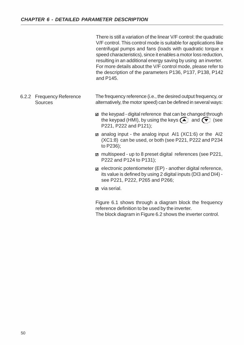
The frequency reference (i.e., the desired output frequency, oralternatively, the motor speed) can be defined in several ways:
the keypad - digital reference that can be changed throughthe keypad (HMI), by using the keys and (seeP221, P222 and P121);
analog input - the analog input AI1 (XC1:6) or the AI2(XC1:8) can be used, or both (see P221, P222 and P234to P236);multispeed - up to 8 preset digital references (see P221,P222 and P124 to P131);
electronic potentiometer (EP) - another digital reference,its value is defined by using 2 digital inputs (DI3 and DI4) -see P221, P222, P265 and P266;
via serial.
Figure 6.1 shows through a diagram block the frequencyreference definition to be used by the inverter.The block diagram in Figure 6.2 shows the inverter control.
6.2.2 Frequency ReferenceSources
There is still a variation of the linear V/F control: the quadraticV/F control. This control mode is suitable for applications likecentrifugal pumps and fans (loads with quadratic torque xspeed characteristics), since it enables a motor loss reduction,resulting in an additional energy saving by using an inverter.For more details about the V/F control mode, please refer tothe description of the parameters P136, P137, P138, P142and P145.
51
CHAPTER 6 - DETAILED PARAMETER DESCRIPTION
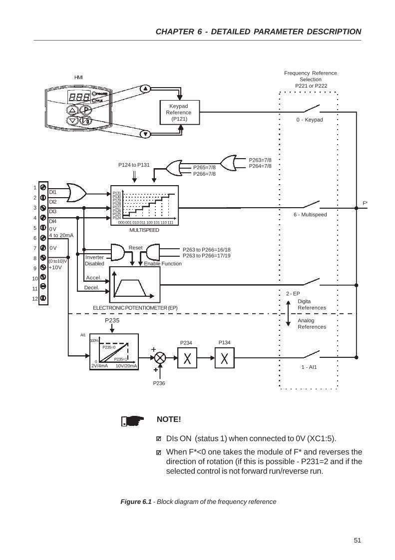
Figure 6.1 - Block diagram of the frequency reference
NOTE!
DIs ON (status 1) when connected to 0V (XC1:5).
When F*<0 one takes the module of F* and reverses thedirection of rotation (if this is possible - P231=2 and if theselected control is not forward run/reverse run.
KeypadReference
(P121)
P124 to P131 P265=7/8P266=7/8
MULTISPEED
Accel.
Enable Function
Decel.
InverterDisabled
ELECTRONIC POTENTIOMETER (EP)
4 to 20mA
DI4
DI3
DI2
1
2
3
4
5
6
7
8
9
10
11
12
AI1
P235
P234 P134
P236
1 - AI1
2 - EP
6 - Multispeed
0 - Keypad
Frequency ReferenceSelection
P221 or P222
F*
DigitaReferences
AnalogReferences
P131P130P129P128P127P126P125P124
000 001 010 011 100 101 110 111
100%
P235=0
P235=102V/4mA 10V/20mA
0V
Reset
HMI
DI1
(0 to10)V+10V
P263=7/8P264=7/8
0V P263 to P266=16/18P263 to P266=17/19

52
CHAPTER 6 - DETAILED PARAMETER DESCRIPTION
NOTE!
In V/F control mode (P202=0 or 1), Fe = F* (see Fig. 6.1) ifP138=0 (slip compensation disabled). If P138≠0, see Fi-gure 6.9 for the relation between Fe and F*.
Figure 6.2 - Inverter block diagram
Fe
Command viaDigital Input
(DI)
Acceleration&Deceleration
Ramp #2
Acceleration &Deceleration
Ramp
P102 P103
P100 P101
DC LinkRegulation
P151
P151
Ud
P133 P134
FrequencyReference
Limits
P202 P295
InverterControl(V/F orVector)
P136, P137,P138, P142,P145
Motor Parameters(P399 to P409)
P178
Vs
PWM
P169
Is
OutputCurrentLimiting
I
Vs
Ud
PowerSupply
IM3Ø
Is
IsP169
53
CHAPTER 6 - DETAILED PARAMETER DESCRIPTION
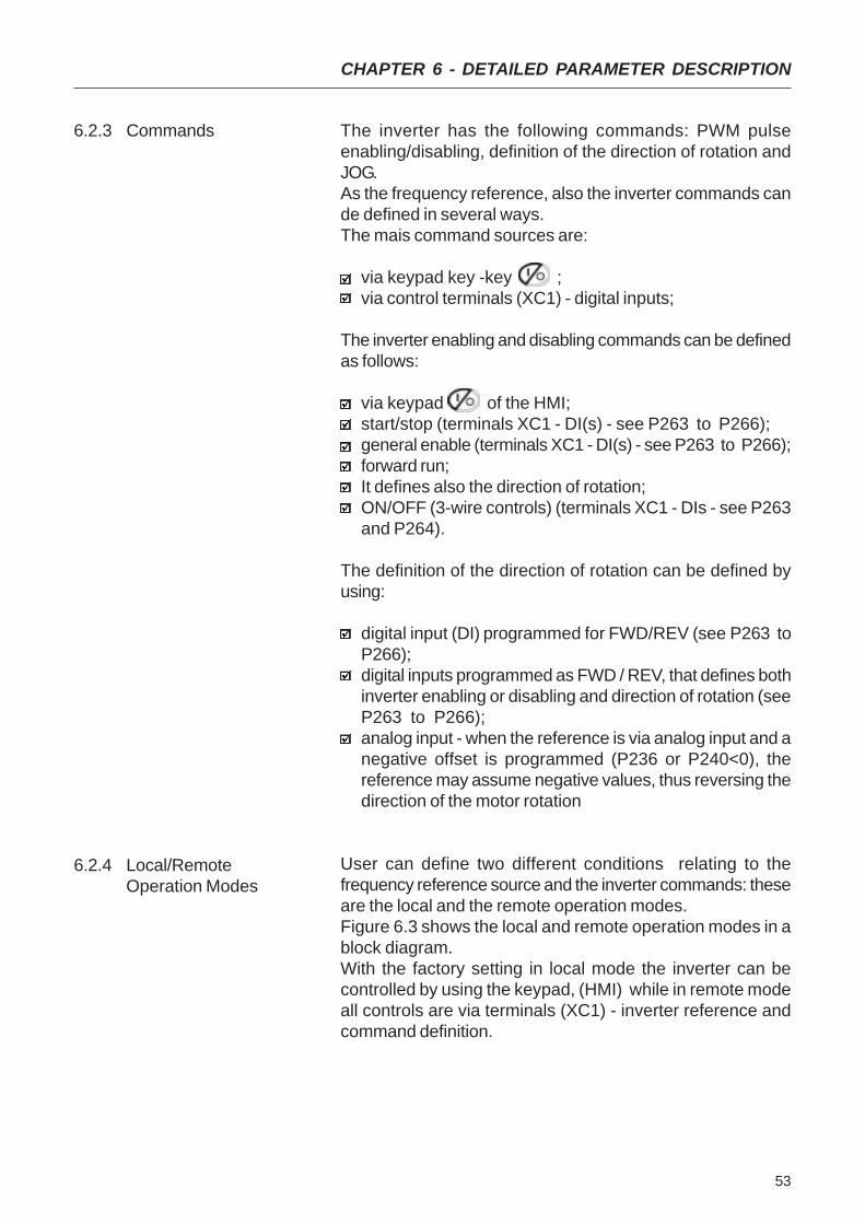
6.2.3 Commands The inverter has the following commands: PWM pulseenabling/disabling, definition of the direction of rotation andJOG.As the frequency reference, also the inverter commands cande defined in several ways.The mais command sources are:
via keypad key -key ;via control terminals (XC1) - digital inputs;
The inverter enabling and disabling commands can be definedas follows:
via keypad of the HMI;start/stop (terminals XC1 - DI(s) - see P263 to P266);general enable (terminals XC1 - DI(s) - see P263 to P266);forward run;It defines also the direction of rotation;ON/OFF (3-wire controls) (terminals XC1 - DIs - see P263and P264).
The definition of the direction of rotation can be defined byusing:
digital input (DI) programmed for FWD/REV (see P263 toP266);digital inputs programmed as FWD / REV, that defines bothinverter enabling or disabling and direction of rotation (seeP263 to P266);analog input - when the reference is via analog input and anegative offset is programmed (P236 or P240<0), thereference may assume negative values, thus reversing thedirection of the motor rotation
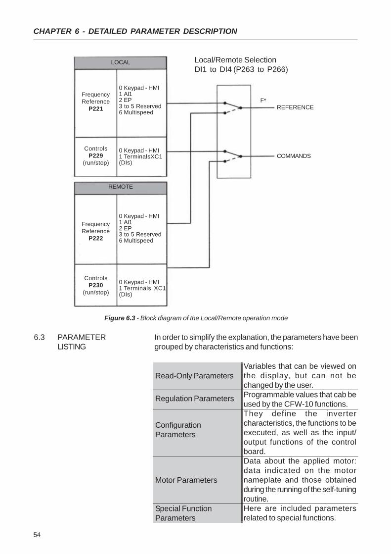
User can define two different conditions relating to thefrequency reference source and the inverter commands: theseare the local and the remote operation modes.Figure 6.3 shows the local and remote operation modes in ablock diagram.With the factory setting in local mode the inverter can becontrolled by using the keypad, (HMI) while in remote modeall controls are via terminals (XC1) - inverter reference andcommand definition.
6.2.4 Local/RemoteOperation Modes
54
CHAPTER 6 - DETAILED PARAMETER DESCRIPTION
Figure 6.3 - Block diagram of the Local/Remote operation mode
6.3 PARAMETERLISTING
In order to simplify the explanation, the parameters have beengrouped by characteristics and functions:
LOCAL
FrequencyReference
P221
ControlsP229
(run/stop)
0 Keypad - HMI1 AI12 EP3 to 5 Reserved6 Multispeed
0 Keypad - HMI1 TerminalsXC1(DIs)
REMOTE
FrequencyReference
P222
ControlsP230
(run/stop)
0 Keypad - HMI1 AI12 EP3 to 5 Reserved6 Multispeed
0 Keypad - HMI1 Terminals XC1(DIs)
REFERENCE
COMMANDS
Local/Remote SelectionDI1 to DI4 (P263 to P266)
F*
Read-Only Parameters
Regulation Parameters
ConfigurationParameters
Motor Parameters
Special FunctionParameters
Variables that can be viewed onthe display, but can not bechanged by the user.Programmable values that cab beused by the CFW-10 functions.They define the invertercharacteristics, the functions to beexecuted, as well as the input/output functions of the controlboard.Data about the applied motor:data indicated on the motornameplate and those obtainedduring the running of the self-tuningroutine.Here are included parametersrelated to special functions.
55
CHAPTER 6 - DETAILED PARAMETER DESCRIPTION
Range[Factory Setting]
Parameter Description / NotesP000 0 to 999Access [ 0 ]Parameter 1
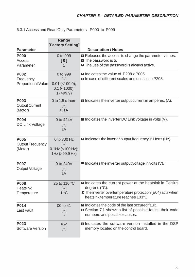
6.3.1 Access and Read Only Parameters - P000 to P099
P002 0 to 999Frequency [ - ]Proportional Value 0.01 (<100.0);
0.1 (<1000);1 (>99.9)
P003 0 to 1.5 x InomOutput Current [ - ](Motor) 0.1A
P004 0 to 424VDC Link Voltage [ - ]
1V
Releases the access to change the parameter values.The password is 5.The use of the password is always active.
Indicates the value of P208 x P005.In case of different scales and units, use P208.
Indicates the inverter output current in ampères. (A).
Indicates the inverter DC Link voltage in volts (V).
P005 0 to 300 HzOutput Frequency [ - ](Motor) 0.1Hz (<100 Hz);
1Hz (>99.9 Hz)
Indicates the inverter output frequency in Hertz (Hz).
P007 0 to 240VOutput Voltage [ - ]
1V
Indicates the inverter output voltage in volts (V).
P008 25 to 110 oCHeatsink [ - ]Temperature 1 oC
Indicates the current power at the heatsink in Celsiusdegrees (°C).The inverter overtemperature protection (E04) acts whenheatsink temperature reaches 103ºC:
P014 00 to 41Last Fault [ - ]
-
Indicates the code of the last occured fault.Section 7.1 shows a list of possible faults, their codenumbers and possible causes.
P023 x.yzSoftware Version [ - ]
Indicates the software version installed in the DSPmemory located on the control board.

56
CHAPTER 6 - DETAILED PARAMETER DESCRIPTION
Range[Factory Setting]
Parameter Description / Notes0.1 to 999s
[ 5.0s ]0.1s (<100);1s (>99.9)0.1 to 999s
[ 10.0s ]0.1s (<100);1s (>99.9)0.1 to 999s
[ 5.0s ]0.1s (<100);1s (>99.9)0.1 to 999s
[ 10.0s ]0.1s (<100);1s (>99.9)
This set of parameters defines the time to acceleratelinearly from zero up to the rated frequency and todecelerate linearly from the rated frequency down to zero.The rated frequency is defined by parameter P145 .When factory setting is used, inverter always follows thetime defined in P100 and P101.If Ramp #2 should be used, where the acceleration anddeceleration times follow the values programmed atP102 and P103, use a digital input. See parameters P263to P265.Depending on the load inertia, too short acceleration ti-mes can disable the inverter due to overcurrent (E00).Depending on the load inertia, too short deceleration ti-mes can disable the inverter due to overvoltage (E01).For more details, refer to P151.
6.3.2 Regulation Parameters - P100 to P199
P104 0 to 2Ramp S [ 0 - Inactive ]
-
The ramp S reduces mechanical stress during the theload acceleration and deceleration.
Figure 6.4 - S or linear Ramp
It is recommended to use the S ramp with digitalfrequency/speed references.
P100AccelerationTime
P101DecelerationTime
P102AccelerationTime2a RampP103DecelerationTime2a Ramp
P104012
Ramp SInactive
50%100%
Output Frequency(Motor Speed)
Linear
t (s)taccel. time
(P100/102)tdecel. time(P101/103)
50% ramp S
100% ramp S

57
CHAPTER 6 - DETAILED PARAMETER DESCRIPTION
Range[Factory Setting]
Parameter Description / NotesP120 0 to 2Digital Reference [ 1 - active]Backup -
Defines if the inverter should save or not the last useddigital reference. This backup function is only applicableto the keypad reference (P12).
If the digital reference backup is inactive (P120=0), thereference will be equal to the minimum frequency everytime the inverter is enabled, according to P133.When P120=1, inverter saves automatically the digitalreference value, (independent of the reference source,keypad, EP).This occurs always when inverter disable is present,independent of the present disable condition (ramp orgeneral), error or undevoltage.When P120=2, the initial reference will be given byP121,and saved always the inverter is enabled.Application example: reference via EP when inverter isdisabled via digital input and decelerates EP (coming toreference 0).However at a new enable, it is desired that the inverterreturns to a frequency different from the minimumfrequency, which will be saved at Parameter P121.
P121 P133 to P134Frequency [ 3.0Hz ]Reference by 0.1Hz (<100Hz);
key and 1Hz (>99.9Hz)
Defines the keypad reference value that can be set byusing the keys and when the parameters P002or P005 are being displayed on the HMI Display.The keys and are enabled if P221=0 (in localmode) or P222=0 (in remote mode).The value of P121is maintained at the last set value, even when inverter isdisabled or turned OFF, provided P120=1 or 2 (backupactive).
P12001
2
Reference BackupInactiveActive
Active, but always given by P121,independently of the source reference
Defines the frequency reference (speed) for the JOGfunction.The JOG function can be activated by using the digitalinputsThe inverter must be disabled by ramp (stopped motor)to operate in the JOG function. Thus if the control sourceis via terminal, there must be at least one digital inputprogrammed as start/stop enabling (otherwise E24 willbe displayed), which must be OFF to enable the JOGfunction via digital input. (See P263 to P266).The direction of rotation is defined by the parameter P231.
P122 P133 to P134JOG Reference [ 5.0Hz ]
0.1Hz (<100Hz);1Hz (>99.9Hz)
58
CHAPTER 6 - DETAILED PARAMETER DESCRIPTION
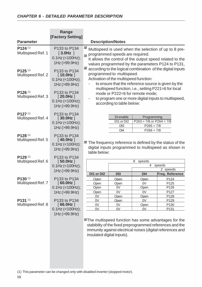
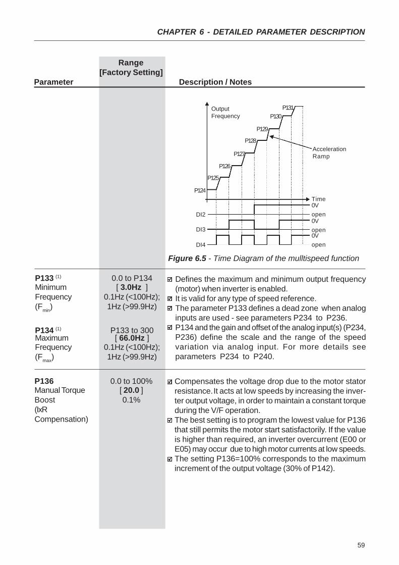
Multispeed is used when the selection of up to 8 pre-programmed speeds are required.It allows the control of the output speed related to thevalues programmed by the parameters P124 to P131,according to the logical combination of the digital inputsprogrammed to multispeed.Activation of the multispeed function:- to ensure that the reference source is given by the
multispeed function, i.e., setting P221=6 for localmode or P222=6 for remote mode;
- to program one or more digital inputs to multispeed,according to table below:
The frequency reference is defined by the status of thedigital inputs programmed to multispeed as shown intable below:
The multispeed function has some advantages for thestabibilty of the fixed preprogrammed references and theimmunity against electrical noises (digital references andinsulated digital inputs).
Range[Factory Setting]
Parameter Description/NotesP124 (1) P133 to P134Multispeed Ref. 1 [ 3.0Hz ]
0.1Hz (<100Hz);1Hz (>99.9Hz)
P125 (1) P133 to P134Multispeed Ref. 2 [ 10.0Hz ]
0.1Hz (<100Hz);1Hz (>99.9Hz)
P126 (1) P133 to P134Multispeed Ref. 3 [ 20.0Hz ]
0.1Hz (<100Hz);1Hz (>99.9Hz)
P127 (1) P133 to P134Multispeed Ref. 4 [ 30.0Hz ]
0.1Hz (<100Hz);1Hz (>99.9Hz)
P128 (1) P133 to P134Multispeed Ref. 5 [ 40.0Hz ]
0.1Hz (<100Hz);1Hz (>99.9Hz)
P129 (1) P133 to P134Multispeed Ref. 6 [ 50.0Hz ]
0.1Hz (<100Hz);1Hz (>99.9Hz)
P130 (1) P133 to P134Multispeed Ref. 7 [ 60.0Hz ]
0.1Hz (<100Hz);1Hz (>99.9Hz)
P131 (1) P133 to P134Multispeed Ref. 8 [ 66.0Hz ]
0.1Hz (<100Hz);1Hz (>99.9Hz)
DI enable ProgrammingDI1 or DI2 P263 = 7/8 or P264 = 7/8
DI3 P265 = 7/8DI4 P266 = 7/8
DI1 or DI2 DI3 DI4 Freq. ReferenceOpen Open Open P124Open Open 0V P125Open 0V Open P126Open 0V 0V P1270V Open Open P1280V Open 0V P1290V 0V Open P1300V 0V 0V P131
8 speeds 4 speeds 2 speeds
(1) This parameter can be changed only with disabled inverter (stopped motor).
59
CHAPTER 6 - DETAILED PARAMETER DESCRIPTION
Figure 6.5 - Time Diagram of the mulltispeed function
AccelerationRamp
Time0V
DI2
DI3
DI4
open0Vopen0Vopen
P124
P125
P126
P127
P128
P129
P130P131Output
Frequency
Range[Factory Setting]
Parameter Description / Notes
P133 (1) 0.0 to P134Minimum [ 3.0Hz ]Frequency 0.1Hz (<100Hz);(Fmin) 1Hz (>99.9Hz)
P134 (1) P133 to 300Maximum [ 66.0Hz ]Frequency 0.1Hz (<100Hz);(Fmax) 1Hz (>99.9Hz)
Defines the maximum and minimum output frequency(motor) when inverter is enabled.It is valid for any type of speed reference.The parameter P133 defines a dead zone when analoginputs are used - see parameters P234 to P236.P134 and the gain and offset of the analog input(s) (P234,P236) define the scale and the range of the speedvariation via analog input. For more details seeparameters P234 to P240.
P136 0.0 to 100%Manual Torque [ 20.0 ]Boost 0.1%(IxRCompensation)
Compensates the voltage drop due to the motor statorresistance.It acts at low speeds by increasing the inver-ter output voltage, in order to maintain a constant torqueduring the V/F operation.The best setting is to program the lowest value for P136that still permits the motor start satisfactorily. If the valueis higher than required, an inverter overcurrent (E00 orE05) may occur due to high motor currents at low speeds.The setting P136=100% corresponds to the maximumincrement of the output voltage (30% of P142).
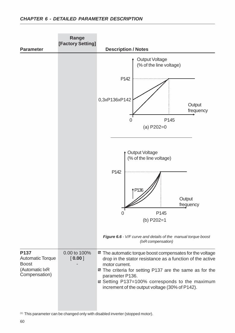
60
CHAPTER 6 - DETAILED PARAMETER DESCRIPTION
Range[Factory Setting]
Parameter Description / Notes
Figure 6.6 - V/F curve and details of the manual torque boost(IxR compensation)
P137 0.00 to 100%Automatic Torque [ 0.00 ]Boost -(Automatic IxRCompensation)
The automatic torque boost compensates for the voltagedrop in the stator resistance as a function of the activemotor current.The criteria for setting P137 are the same as for theparameter P136.Setting P137=100% corresponds to the maximumincrement of the output voltage (30% of P142).
(1) This parameter can be changed only with disabled inverter (stopped motor).
Output Voltage(% of the line voltage)
P142
P136
0 P145
Outputfrequency
(b) P202=1
Output Voltage(% of the line voltage)
P142
0,3xP136xP142
0 P145
Outputfrequency
(a) P202=0
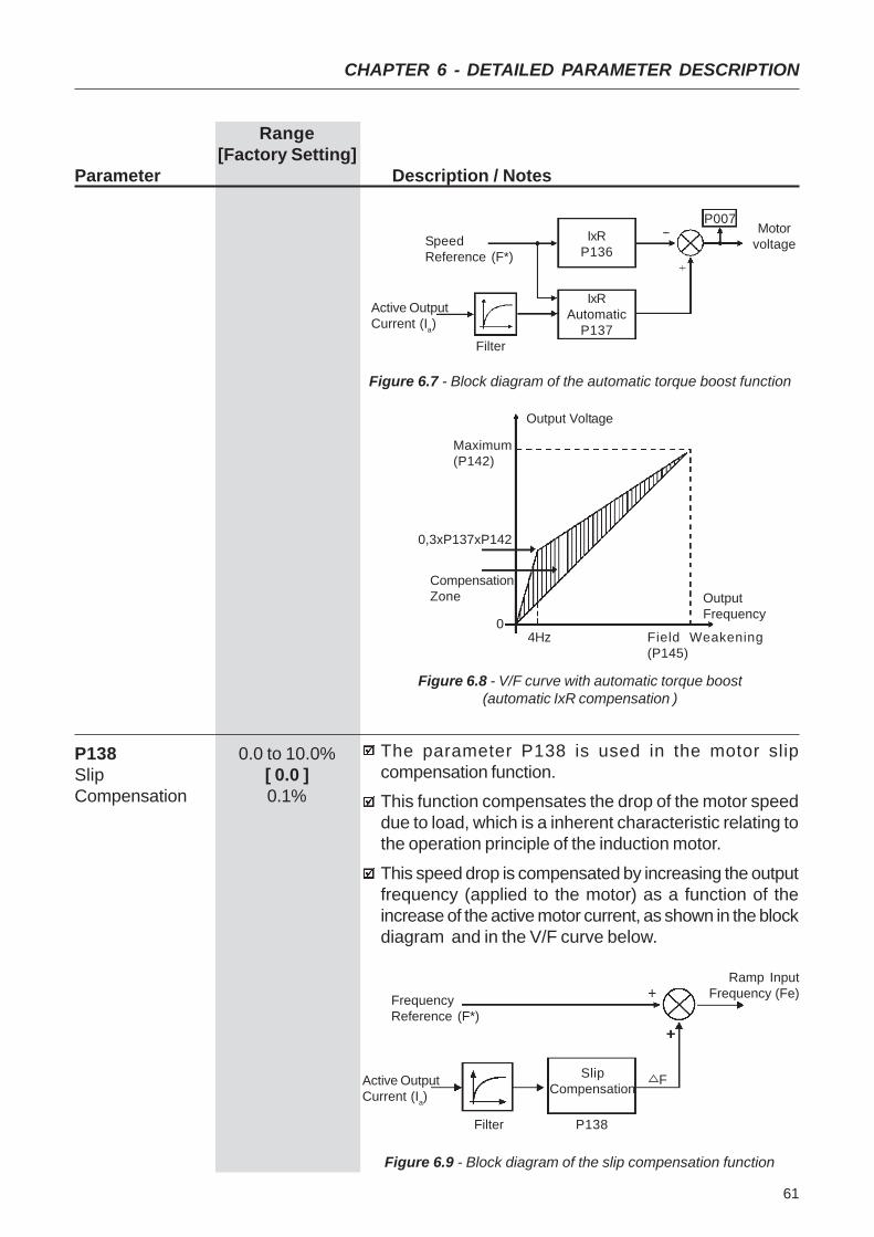
61
CHAPTER 6 - DETAILED PARAMETER DESCRIPTION
Range[Factory Setting]
Parameter Description / Notes
Figure 6.7 - Block diagram of the automatic torque boost function
Figure 6.8 - V/F curve with automatic torque boost(automatic IxR compensation )
P138 0.0 to 10.0%Slip [ 0.0 ]Compensation 0.1%
The parameter P138 is used in the motor slipcompensation function.This function compensates the drop of the motor speeddue to load, which is a inherent characteristic relating tothe operation principle of the induction motor.
This speed drop is compensated by increasing the outputfrequency (applied to the motor) as a function of theincrease of the active motor current, as shown in the blockdiagram and in the V/F curve below.
SpeedReference (F*)
Active OutputCurrent (Ia)
Filter
IxRAutomatic
P137
IxRP136
P007Motor
voltage
CompensationZone
Maximum(P142)
Output Voltage
OutputFrequency
Field Weakening(P145)
4Hz0
0,3xP137xP142
SlipCompensationActive Output
Current (Ia)
FrequencyReference (F*)
Ramp InputFrequency (Fe)
F
Filter P138
Figure 6.9 - Block diagram of the slip compensation function
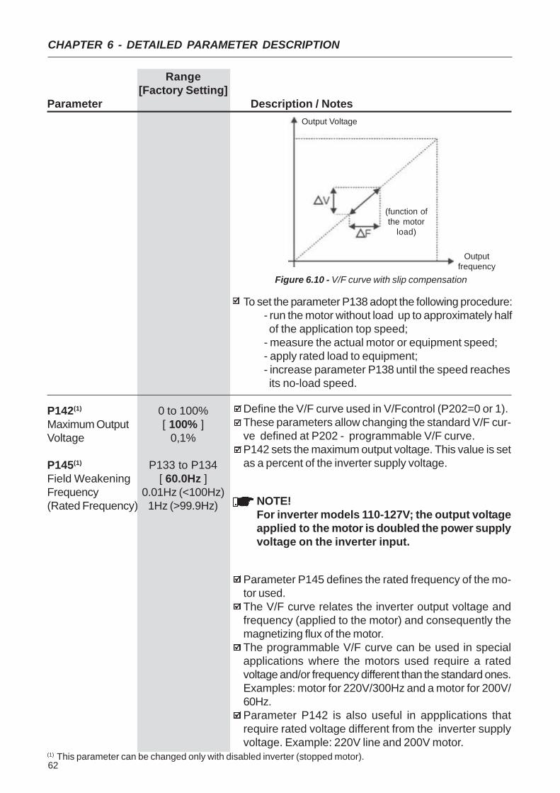
62
CHAPTER 6 - DETAILED PARAMETER DESCRIPTION
Range[Factory Setting]
Parameter Description / Notes
Figure 6.10 - V/F curve with slip compensation
Output Voltage
(function ofthe motor
load)
Outputfrequency
To set the parameter P138 adopt the following procedure:- run the motor without load up to approximately half of the application top speed;- measure the actual motor or equipment speed;- apply rated load to equipment;- increase parameter P138 until the speed reaches its no-load speed.
P142(1) 0 to 100%Maximum Output [ 100% ]Voltage 0,1%
P145(1) P133 to P134Field Weakening [ 60.0Hz ]Frequency 0.01Hz (<100Hz)(Rated Frequency) 1Hz (>99.9Hz)
Define the V/F curve used in V/Fcontrol (P202=0 or 1).These parameters allow changing the standard V/F cur-ve defined at P202 - programmable V/F curve.P142 sets the maximum output voltage. This value is setas a percent of the inverter supply voltage.
NOTE!For inverter models 110-127V; the output voltageapplied to the motor is doubled the power supplyvoltage on the inverter input.
Parameter P145 defines the rated frequency of the mo-tor used.The V/F curve relates the inverter output voltage andfrequency (applied to the motor) and consequently themagnetizing flux of the motor.The programmable V/F curve can be used in specialapplications where the motors used require a ratedvoltage and/or frequency different than the standard ones.Examples: motor for 220V/300Hz and a motor for 200V/60Hz.Parameter P142 is also useful in appplications thatrequire rated voltage different from the inverter supplyvoltage. Example: 220V line and 200V motor.
(1) This parameter can be changed only with disabled inverter (stopped motor).

63
CHAPTER 6 - DETAILED PARAMETER DESCRIPTION
Range[Factory Setting]
Parameter Description / Notes
P151 360 to 460VDC Link Volage (line 110-127V)Regulation Level [ 430V ]
1V
325 to 410V(line 200-240V)
[ 380V ]1V
The DC link voltage regulation (ramp holding) avoids in-verter disable due to overvoltage trips (E01) duringdeceleration of loads with high inertia or shortdeceleration times.It acts in order to increase the deceleration time(according to load - inertia), thus avoiding the E01activation.
Figure 6.12 - Deceleration curve with DC Link voltage regulation
By this function an optimized deceleration time(minimum) is achieved for the driven load.This function is useful in applications with medium inertiathat require short deceleration times.In case of overvoltage trip during the decelearation, youmust reduce gradually the value of P151 or increase thetime of the deceleration ramp (P101 and/or P103).
Figure 6.11 - Adjustable V/F curve
Ouput Voltage
OutputFrequencyP1450.1Hz
0
P142
E01 - Overvoltage
Hardware limit
CI VoltageUd (P004)
Time
OutputFrequency
(MotorSpeed )
Rated Ud
P151
Time
DC LinkVoltage
(1) This parameter can be changed only with disabled inverter (stopped motor).

64
CHAPTER 6 - DETAILED PARAMETER DESCRIPTION
Range[Factory Setting]
Parameter Description / Notes
Figure 6.13 - Ixt function – Overload detection
Prevents motor stalling during an overload. If motor loadincreases its current will increase too. If the motor currentattempts to exceed the value set at P169, the motor speedwill be decreased by following the deceleration ramp untilthe current becomes lower than P169. As soon as theoverload condition disappears, the motor speed isresumed.
P169 0.0xPInom to 2.0xPInomMaximum Output [ 1.5xP295 ]Current 0.1% (<100%);
1% (>99.9%)
Parameter P156 must be set from 10% to 20% higherthan the rated motor current.
Figure 6.14 – Curves showing the operation of the current limitation
Timeduringcontinuous
duty
Time
Motor Current
Deceleration ramp (P101/P103)during
decelerationduring
acceleration
Accelerationramp
(P100/P102)
Speed
P169
The motor will not stop if the line is permanently withovervoltage (Ud>P151). In this case, reduce the linevoltage, or increase the value of P151.If even with these settings the motor does not deceleratewithin the required time, you will have the alternative toincrease P136;
P156 0.3xPInom to 1.3xPInomMotor Overload [ 1,2xP295 ]Current 0.1A
This function is used to protect the motor against overload(Ixt function - E05).The motor overload current is the current level above whichthe inverter will consider the motor operating underoverload. The higher the difference between the motorcurrent and the overload current, the sooner the Ixt function- E05 - will act.
3,0
2,01,5
1,0
15 30 60 90Time (s)
Motor Current (P003)Overload Current
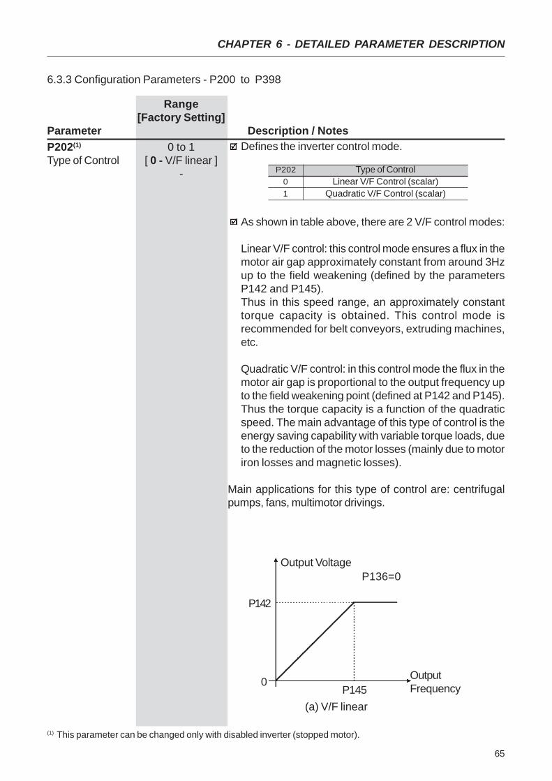
65
CHAPTER 6 - DETAILED PARAMETER DESCRIPTION
Range[Factory Setting]
Parameter Description / NotesDefines the inverter control mode.P202(1) 0 to 1
Type of Control [ 0 - V/F linear ]-
As shown in table above, there are 2 V/F control modes:
Linear V/F control: this control mode ensures a flux in themotor air gap approximately constant from around 3Hzup to the field weakening (defined by the parametersP142 and P145).Thus in this speed range, an approximately constanttorque capacity is obtained. This control mode isrecommended for belt conveyors, extruding machines,etc.
Quadratic V/F control: in this control mode the flux in themotor air gap is proportional to the output frequency upto the field weakening point (defined at P142 and P145).Thus the torque capacity is a function of the quadraticspeed. The main advantage of this type of control is theenergy saving capability with variable torque loads, dueto the reduction of the motor losses (mainly due to motoriron losses and magnetic losses).
Main applications for this type of control are: centrifugalpumps, fans, multimotor drivings.
6.3.3 Configuration Parameters - P200 to P398
P20201
Type of ControlLinear V/F Control (scalar)
Quadratic V/F Control (scalar)
Output VoltageP136=0
P142
0P145
OutputFrequency
(a) V/F linear
(1) This parameter can be changed only with disabled inverter (stopped motor).
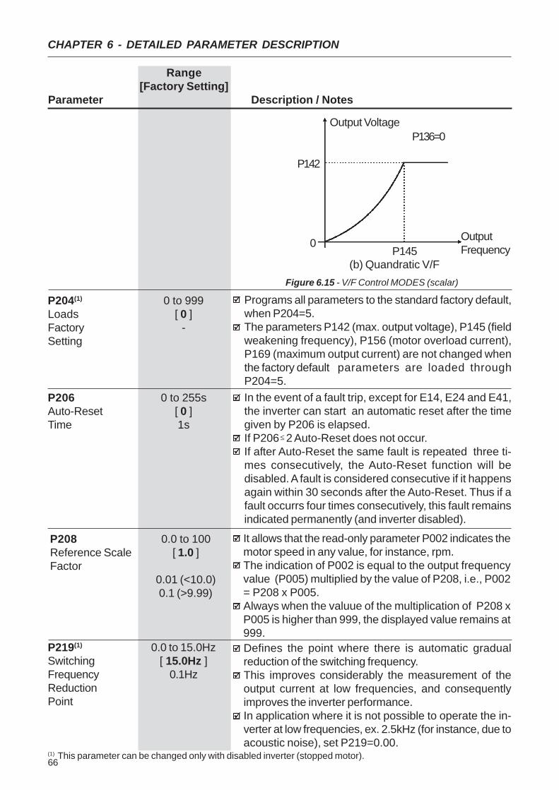
66
CHAPTER 6 - DETAILED PARAMETER DESCRIPTION
Range[Factory Setting]
Parameter Description / Notes
Figure 6.15 - V/F Control MODES (scalar)
Output VoltageP136=0
P142
0P145
OutputFrequency
(b) Quandratic V/F
(1) This parameter can be changed only with disabled inverter (stopped motor).
Programs all parameters to the standard factory default,when P204=5.The parameters P142 (max. output voltage), P145 (fieldweakening frequency), P156 (motor overload current),P169 (maximum output current) are not changed whenthe factory default parameters are loaded throughP204=5.
P204(1) 0 to 999Loads [ 0 ]Factory -Setting
In the event of a fault trip, except for E14, E24 and E41,the inverter can start an automatic reset after the timegiven by P206 is elapsed.If P206 2 Auto-Reset does not occur.If after Auto-Reset the same fault is repeated three ti-mes consecutively, the Auto-Reset function will bedisabled. A fault is considered consecutive if it happensagain within 30 seconds after the Auto-Reset. Thus if afault occurrs four times consecutively, this fault remainsindicated permanently (and inverter disabled).
P206 0 to 255sAuto-Reset [ 0 ]Time 1s
≥
It allows that the read-only parameter P002 indicates themotor speed in any value, for instance, rpm.The indication of P002 is equal to the output frequencyvalue (P005) multiplied by the value of P208, i.e., P002= P208 x P005.Always when the valuue of the multiplication of P208 xP005 is higher than 999, the displayed value remains at999.
P208 0.0 to 100Reference Scale [ 1.0 ]Factor
0.01 (<10.0)0.1 (>9.99)
P219(1) 0.0 to 15.0HzSwitching [ 15.0Hz ]Frequency 0.1HzReductionPoint
Defines the point where there is automatic gradualreduction of the switching frequency.This improves considerably the measurement of theoutput current at low frequencies, and consequentlyimproves the inverter performance.In application where it is not possible to operate the in-verter at low frequencies, ex. 2.5kHz (for instance, due toacoustic noise), set P219=0.00.
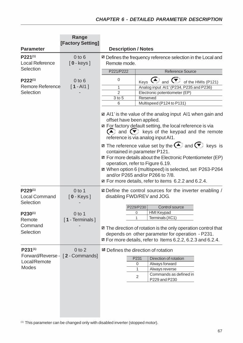
67
CHAPTER 6 - DETAILED PARAMETER DESCRIPTION
Range[Factory Setting]
Parameter Description / NotesP221(1) 0 to 6Local Reference [ 0 - keys ]Selection -
P222(1) 0 to 6Remore Reference [ 1 - AI1 ]Selection -
Defines the frequency reference selection in the Local andRemote mode.
P221/P222
0
12
3 to 56
Reference Source
Keys and of the HMIs (P121)Analog input AI1' (P234, P235 and P236)Electronic potentiometer (EP)RerservedMultispeed (P124 to P131)
P230(1) 0 to 1Remote [ 1 - Terminals ]Command - The direction of rotation is the only operation control that
depends on other parameter for operation - P231.For more details, refer to Items 6.2.2, 6.2.3 and 6.2.4.
P229(1) 0 to 1Local Command [ 0 - Keys ]Selection -
Define the control sources for the inverter enabling /disabling FWD/REV and JOG.
AI1’ is the value of the analog input AI1 when gain andoffset have been applied.For factory default setting, the local reference is via and keys of the keypad and the remotereference is via analog input AI1.
The reference value set by the and keys iscontained in parameter P121.For more details about the Electronic Potentiometer (EP)operation, refer to Figure 6.19.When option 6 (multispeed) is selected, set P263-P264and/or P265 and/or P266 to 7/8.For more details, refer to items 6.2.2 and 6.2.4.
P229/P23001
Control sourceHMI KeypadTerminals (XC1)
P231(1) 0 to 2Forward/Reverse - [ 2 - Commands]Local/RemoteModes
Defines the direction of rotationP231
01
2
Direction of rotationAlways forwardAlways reverseCommands as defined inP229 and P230
Selection
(1) This parameter can be changed only with disabled inverter (stopped motor).
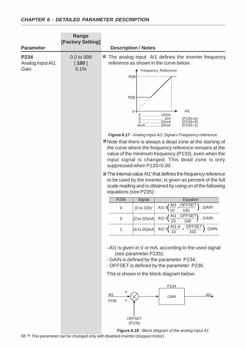
68
CHAPTER 6 - DETAILED PARAMETER DESCRIPTION
Range[Factory Setting]
Parameter Description / Notes
Note that there is always a dead zone at the starting ofthe curve where the frequency reference remains at thevalue of the minimum frequency (P133), even when theinput signal is changed. This dead zone is onlysuppressed when P133=0.00.
The internal value AI1’ that defines the frequency referenceto be used by the inverter, is given as percent of the fullscale reading and is obtained by using on of the followingequations (see P235):
Figure 6.17 - Analog Input AI1 Signal x Frequency reference.
P234 0.0 to 999Analog Input AI1 [ 100 ]Gain 0.1%
The analog input AI1 defines the inverter frequencyreference as shown in the curve below.
P134
P133
AI100 .................. 100%0 ..................... 10V (P235=0)0 .................. 20mA (P235=0)
4mA.............. 20mA (P235=1)
Frequency Reference
- AI1 is given in V or mA, according to the used signal (see parameter P235);
- GAIN is defined by the parameter P234;- OFFSET is defined by the parameter P236.This is shown in the block diagram below:
P235
0
0
1
Signal
(0 to 10)V
(0 to 20)mA
(4 to 20)mA
Equation
AI1'= AI1 +OFFSET . GAIN 10 100
AI1'= AI1 +OFFSET . GAIN 20 100
AI1'= AI1-4 + OFFSET . GAIN 16 100
(((
((
(
GAIN
P234
AI1'
OFFSET(P236)
P235AI1
Figura 6.18 - Block diagram of the analog input A1 (1)
This parameter can be changed only with disabled inverter (stopped motor).
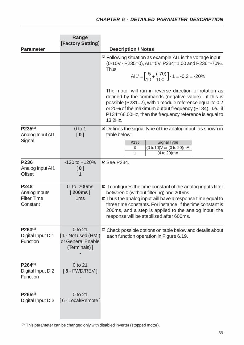
69
CHAPTER 6 - DETAILED PARAMETER DESCRIPTION
Range[Factory Setting]
Parameter Description / NotesFollowing situation as example:AI1 is the voltage input(0-10V - P235=0), AI1=5V, P234=1.00 and P236=-70%.Thus
The motor will run in reverse direction of rotation asdefined by the commands (negative value) - if this ispossible (P231=2), with a module reference equal to 0.2or 20% of the maximum output frequency (P134). I.e., ifP134=66.00Hz, then the frequency reference is equal to13.2Hz.
P235(1) 0 to 1Analog Input AI1 [ 0 ]Signal
Defines the signal type of the analog input, as shown intable below:
P236 -120 to +120%Analog Input AI1 [ 0 ]Offset 1
See P234.
AI1' = 5 + (-70) . 1 = -0.2 = -20% 10 100[ [
P23501
Signal Type(0 to10)V or (0 to 20)mA
(4 to 20)mA
P248 0 to 200msAnalog Inputs [ 200ms ]Filter Time 1msConstant
It configures the time constant of the analog inputs filterbetween 0 (without filtering) and 200ms.Thus the analog input will have a response time equal tothree time constants. For instance, if the time constant is200ms, and a step is applied to the analog input, theresponse will be stabilized after 600ms.
P263(1) 0 to 21Digital Input DI1 [ 1 - Not used (HMI)Function or General Enable
(Terminals) ]-
P264(1) 0 to 21Digital Input DI2 [ 5 - FWD/REV ]Function -
P265(1) 0 to 21Digital Input DI3 [ 6 - Local/Remote ]
Check possible options on table below and details abouteach function operation in Figure 6.19.
(1) This parameter can be changed only with disabled inverter (stopped motor).
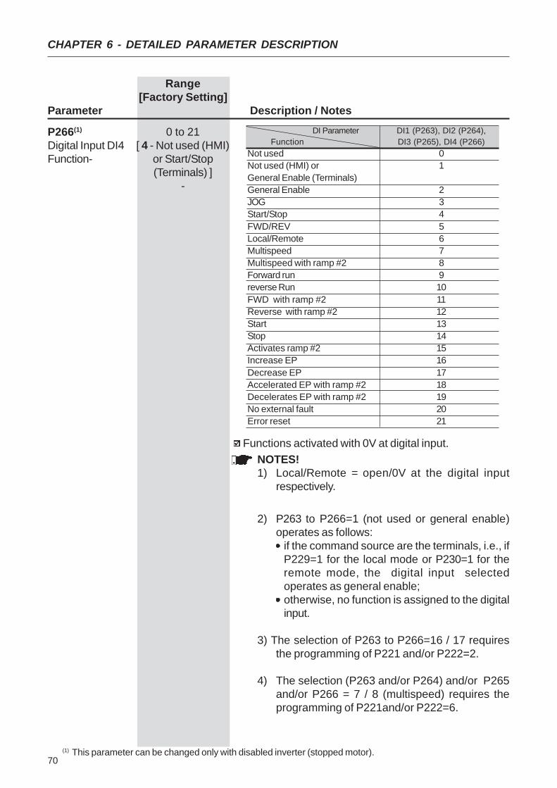
70
CHAPTER 6 - DETAILED PARAMETER DESCRIPTION
Range[Factory Setting]
Parameter Description / Notes
P266(1) 0 to 21Digital Input DI4 [ 4 - Not used (HMI)Function- or Start/Stop
(Terminals) ]-
Functions activated with 0V at digital input.
DI Parameter DI1 (P263), DI2 (P264),Function DI3 (P265), DI4 (P266)
Not used 0Not used (HMI) or 1General Enable (Terminals)General Enable 2JOG 3Start/Stop 4FWD/REV 5Local/Remote 6Multispeed 7Multispeed with ramp #2 8Forward run 9reverse Run 10FWD with ramp #2 11Reverse with ramp #2 12Start 13Stop 14Activates ramp #2 15Increase EP 16Decrease EP 17Accelerated EP with ramp #2 18Decelerates EP with ramp #2 19No external fault 20Error reset 21
(1) This parameter can be changed only with disabled inverter (stopped motor).
NOTES!1) Local/Remote = open/0V at the digital input
respectively.
2) P263 to P266=1 (not used or general enable)operates as follows:
if the command source are the terminals, i.e., ifP229=1 for the local mode or P230=1 for theremote mode, the digital input selectedoperates as general enable;otherwise, no function is assigned to the digitalinput.
3) The selection of P263 to P266=16 / 17 requiresthe programming of P221 and/or P222=2.
4) The selection (P263 and/or P264) and/or P265and/or P266 = 7 / 8 (multispeed) requires theprogramming of P221and/or P222=6.

71
CHAPTER 6 - DETAILED PARAMETER DESCRIPTION
Range[Factory Setting]
Parameter Description / Notes
6) If different acceleration and deceleration times aredesired for a given operation condition (forinstance for a set of frequencies or for a directionof rotation), check if it possible to use themultispeed function with ramp #2 and FWD/REVwith ramp #2.
7) Only one digital input can be programmed for eachfunction. If more than one input has beenprogrammed, programming error will b displayed(E24).
a) GENERAL ENABLE b) START/STOP
open
Outputfrequency
(Motorspeed)
motor runsfreely
Time
Time0V
Accel.ramp
D I
0V
Output frequency(Motor speed)
Decel.Ramp
Time
Time
Accel.ramp
openD I
c) 3-WIRE START/STOP
Time
Time
0V
0V
openDI2 - Stop
Time
Time
OutputFrequency
(Motor)
DI1 - Start open
Figure 6.19 a) to c) - Details about the function of the digital inputs

72
CHAPTER 6 - DETAILED PARAMETER DESCRIPTION
d) FORWARD RUN / REVERSE RUN
Figure 6.19 d to g) - Details about the function of the digital inputs
open
Time
0V
Time
Time
0V
openDI2 - REV
DI1 - FWD
Outputfrequency
(Motor speed)
CW
CCW
open
0V
Time
Time
Outputfrequency
(Motor
DI - FWD/
CW
CCW
f) FWD / REV
open
open
0V
Time
0V
Time
P102P100
DI - Start/Stop
DI - Ramp #2
g) RAMP #2
Outputfrequency
(Motor
P103P101
Time
DI4 -Decrease PE
Time
Outputfrequency
(Motorspeed)
0V
open
DI - Start/Stop
MinimumFrequency
(P133)
Reset
DI3 -Increase PE open
Time
Time
Time
0V
0V
e) ELECTRONIC POTENTIOMETER (EP)
open
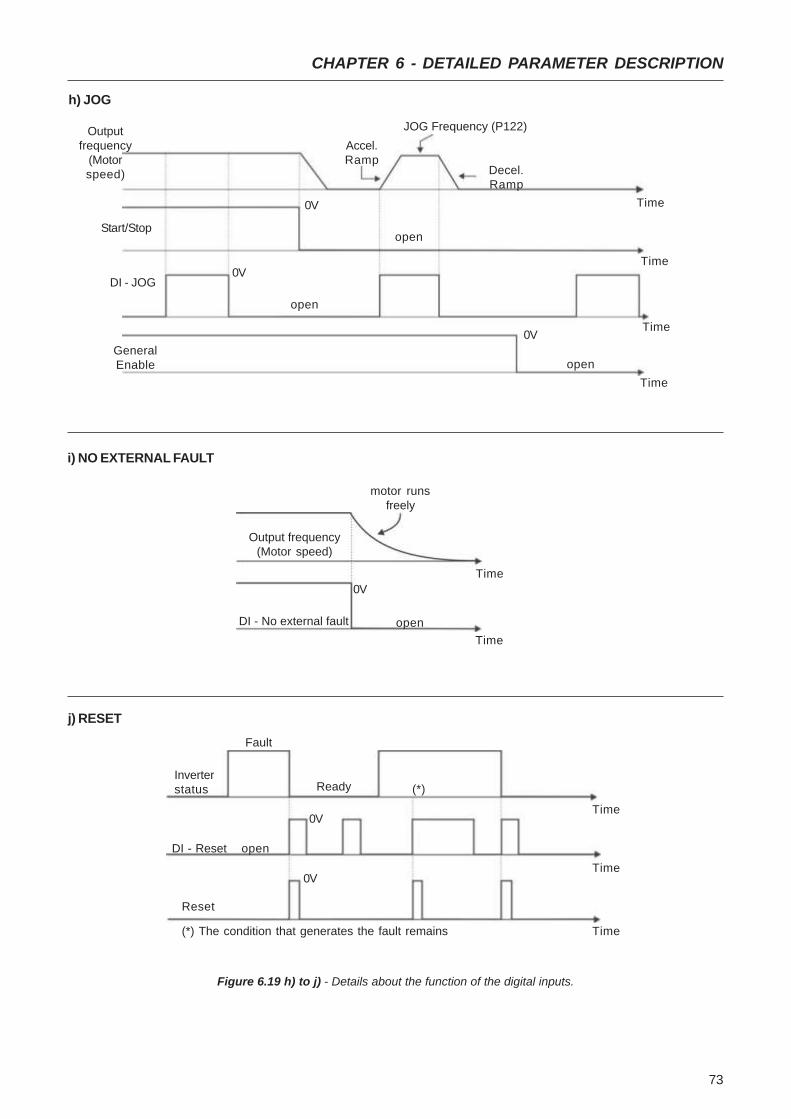
73
CHAPTER 6 - DETAILED PARAMETER DESCRIPTION
Time
Outputfrequency
(Motorspeed)
0V
0V
Start/Stop
JOG Frequency (P122)
Decel.Ramp
0VDI - JOG
GeneralEnable
open
open
open
Accel.Ramp
h) JOG
Time
Time
Time
open
0V
Time
Time
Output frequency(Motor speed)
DI - No external fault
i) NO EXTERNAL FAULT
motor runsfreely
Figure 6.19 h) to j) - Details about the function of the digital inputs.
j) RESET
Fault
Time0V
Time
Time
0V
Ready
Reset
DI - Reset open
Inverterstatus (*)
(*) The condition that generates the fault remains
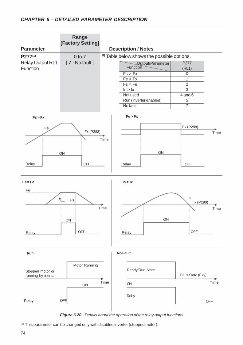
74
CHAPTER 6 - DETAILED PARAMETER DESCRIPTION
Range[Factory Setting]
Parameter Description / NotesP277(1) 0 to 7Relay Output RL1 [ 7 - No fault ]Function
Table below shows the possible options.
Figure 6.20 - Details about the operation of the relay output fucntions
Fs > Fx
FsFx (P288)
Time
OFFRelay
ON
Is > Ix
IsIx (P290)
Time
OFFRelay
ON
Fs = Fe
Fs
Time
OFFRelay
ON
Fe
Fx (P288)Time
OFFRelay
ON
Fe > Fx
Output/Parameter FunctionFs > FxFe > FxFs = FeIs > IxNot usedRun (inverter enabled)No fault
P277(RL1)
0123
4 and 657
(1) This parameter can be changed only with disabled inverter (stopped motor).
Run
Stopped motor orrunning by inertia
Time
OFFRelay
ON
Motor Running
No Fault
Time
OFFRelay
Fault State (Exy)Ready/Run State
ON

75
CHAPTER 6 - DETAILED PARAMETER DESCRIPTION
Range[Factory Setting]
Parameter Unit Description / NotesWhen the definition in the function name is true, the digi-tal output will be activated, i.e., the relay coil is energized.When the option 'Not used' has been programmed, therelay output(s) will be disabled, i.e., the coil is notenergized.Definitions of the used symbols in the functions:
Fs = P005 - output frequency (motor)Fe = Reference frequency (ramp input frequency)Fx = P288 - Fx frequencyIs = P003 - output current (motor)Ix = P290 - Ix current
P288 0.0 to 300HzFrequency Fx [ 3.0Hz ]
0.1Hz (<100Hz);1Hz (>99.9Hz)
P290 0 to 1.5xP295Current Ix [ 1.0xP295 ]
0.1A
Used in the relay output functions Fs>Fx, Fe>Fx e Is>Ix(see P277).
P295 1.6 to 7.3Inverter Rated [ According tocurrent Inverter Rated(Inom) Current ]
-
P295
1.62.64.07.3
Inverter RatedCurrent (Inom)
1.6A2.6A4.0A7.3A
P297(1) 2.5 to 15.0Switching [ 5 kHz ]Frequency 0.1 kHz
Defines the switching frequency of the IGBTs in the inveter.The switching frequency is a comprimise between themotor acoustic noise level and the inverters IGBTs losses.Higher switching frequencies cause lower motor acousticnoise level, but increase the IGBTs losses, increasing thedrive components temperature and thus reducing theiruseful life.The predominant frequency on the motor is twice theswitching frequency setat P297.Thus, P297=5kHz results in an audible motor noisecorresponding to 10kHz. This is due to the used PWMtechnique .The reduction of the switching frequency also contributesto the reduction of instability and ressonance that mayoccur in certain application conditions, as well as reducesthe emission of electromagnetic energy by the inveter.The reduction of the switching frequencies also reducesthe leakage currents to ground.Use currents according to table below:
(1) This parameter can be changed only with disabled inverter (stopped motor).

76
CHAPTER 6 - DETAILED PARAMETER DESCRIPTION
Range[Factory Setting]
Parameter Unit Description / Notes
Before DC braking starts, there is a "Dead Time" (motorruns freely) required for the motor demagnetization. Thistime is function of the motor speed at which the DCbraking occurs (output frequency) .
During the DC braking the LED display flashesIf the inverter is enabled during the braking process, thisprocess will be aborted and motor operates normally.
P300 0.0 to 15.0sDC Braking [ 0.0 ]Time 0.1s
P301 0.0 to 15.0HzDC Braking [ 1.0Hz ]Start Frequency 0.1Hz
P302 0.0 to 100%Braking Torque [ 50.0% ]
0.1%
The DC braking feature provides a motor fast stop viaDC current injection.The applied DC braking current, that is proportional tothe braking torque, is set at P302.The figures below show the DC branking operation atthe two possible conditions: ramp disabling and generaldisabling.
Figure 6.21 - DC braking after ramp disable
Figure 6.22 - DC braking after general disable
Inverter Model / P297
CFW100016S ...CFW100026S ...CFW100040S ... CFW100073S ...
2.5 kHz to5.0 kHz
1.6A2.6A4.0A7.3A
10.1 kHz to15.0 kHz
1.6A2.1A3.4A6.3A
5.1 kHz to10.0 kHz
1.6A2.6A4.0A6.8A
P301 P300
DEADTIME
open
Time
DI - Start/Stop0V
Outpuitfrequency
(Motorspeed)
DC CurrentINJECTION
P300
open
TimeDEADTIME
IDC CurrentINJECTION
DI- GeneralEnable
Outpuitfrequency
(Motorspeed)
0V
(1) This parameter can be changed only with disabled inverter (stopped motor).
77
CHAPTER 6 - DETAILED PARAMETER DESCRIPTION
Range[Factory Setting]
Parameter Unit Description / Notes
DC braking can continue its braking process even afterthe motor has stopped. Pay special attention to thedimensioning of the motor thermal protection for cyclicbraking of short times.In applications where the motor current is lower thanthe rated inverter current, and where the braking torqueis not enough for the braking condition, please contactWEG to optimize the settings.

78
CHAPTER 7
DIAGNOSTICS AND TROUBLESHOOTING
This chapter assists the user to identify and correct possiblefaults that can occur during the CFW-10 operation. Alsoinstructions about required periodical inspections and cleaningprocedures are also provided.
When a fault is detected, the inverter is disabled and the faultcode is displayed on the readout in EXX form, where XX isthe actual fault code.
To restart the inverter after a fault has occurred, the invertermust be reset. The reset can be made as follows:
disconnect and reapply The AC power (power-on reset);press key (manual reset);
automatic reset through P206 (auto-reset);via digital input: DI1 to DI4 (P263 to P266 = 21).
The table below defines each fault code, explains how to resetthe fault and shows the possible causes for each fault code.
7.1 FAULTS ANDPOSSIBLE CAUSES
FAULT RESET (1) POSSIBLE CAUSES
E00 Power-on Short-circuit between two motor phases.Output Manual (key ) If this fauklt occurs during power-up, there may be short-
Overcurrent Auto-Reset circuit between ground and one of more output phases.(between phases) DI Inertia of the load too high, or acceleration ramp too short
P169 set too high.Undue set of P136 and/or P137,IGBT transistor module is short-circuited
E01 Power supply voltage too high, generating in the DC link DC Link a voltage higher than the allowed value:Overvoltage (Ud) Ud>410V - Models 200-240V
Ud>460V - Models 110- 127VLoad inertia too high and acceleration ramp is too shortSetting of P151 too high.
E02 Power supply voltage too low, causing a DC link DC Link voltage higher than the allowed value (read the valueUndervoltage at Parameter P004):
(Ud) Ud<200V - Modelos 200 - 240VUd<250V - Modelos 110 - 127V

79
CHAPTER 7 - DIAGNOSTICS AND TROUBLESHOOTING
Note:(1) In case of E04 Fault due to inverter overtemperature,
allow the inverter to cool down before trying to reset it.
The faults act as follows:
E00 to E06: switches off the relay that has beenprogrammed to “no fault”, disables the PWM pulses,displays the fault code on the display Some data are savedon the EEPROM memory: keypad reference and EP(electronic potentiometer) (when the function “backup ofthe references” at P120 has been enabled), the occurredfault number, the status of the integrator of the IxT function(overcurrent).E24: Indicates the fault code on the LED display.E08, E09, E31 e E41: do not allow inverter operation (it isnot possible to enable the inverter); the fault code isindicated on the LED display.
FAULT RESET (1) POSSIBLE CAUSES
E04 Power-on Ambient temperature too high (>50ºC) and/or output currentInverter Manual (key ) too high.
Overtemperature Auto-reset NOTEDI The heat sink overtemperature protection (E04) is activated
when the heat sink temperature (P008) reaches 103ºC.
E05 P156 set too low for the motor that is being used. Overload Motor is under an actual overload condition. at output
Ixt FunctionE06 Wiring at DI1 to DI4 inputs is open (not connected to
External Error GND (pin 5 of the XC1 control connector)].digital input prografor ext. fault is open)
E08 Electrical noise.CPU Error
E09 Contact WEG Memory with corrupted values.Program Memory (refer to section 7.3)Error (Checksum)
E24 It is automatically reset Incompatible parameters were programmedProgramming when the incompatible Refer to table 5.1.
error parameters are changed
E31 Contact WEG Inverter control circuit is defective.Keypad (HMI) Servicing Electrical noise in the installation (electromagneticConnection Fault (Refer to Item 7.3) interference).
E41 Contact WEG Servicing Inverter power circuit is defective.Self- Diagnosis (refer to section 7.3)
Fault

80
CHAPTER 7 - DIAGNOSTICS AND TROUBLESHOOTING
7.2 TROUBLESHOOTING
PROBLEM POINT TO BE CORRECTIVE ACTION CHECKED
Motor does not run Incorrect wiring 1.Check the power and the control connections. For example,the digital inputs DIx programmed for Start/Stop or General Enable
or No External Fault must be connected to GND (pin 5 of thecontrol connector XC1).
Analog reference 1.Check if the external signal is properly connected.(if used) 2.Check the status of the speed potentiometer (if used).
Incorrect Programming 1.Check if the parameters are properly programmed for theapplication.
Fault 1.Check if the inverter has not been disabled due to detected faultcondition (refer to Table above).
Motor Stall 1.Reduce the motor load.2.Increase P169 or P136/P137.
Motor speed Loose connections 1.Disable the inverter, switch OFF the power supply and tighten alloscillates connections.
Defective speed 1.Replace the defective speed potentiometer.potentiometer
Variation of the external 1.Identify the cause of the variation.analog reference
Motor speed Programming error 1.Check if the contents of P133 (minimum frequency)too high or (reference limits) and P134 (maximum frequency) are according to the motortoo low and the application.
Signal of the 1.Check the control signal level of the reference.Reference Control 2.Check the programming (gains and offset) at P234 to P236.
Motor nameplate 1.Check if the used motor meets the application requirements.data
Display OFF Power supply 1.The power supply must be within the following ranges:200-240V models: - Min: 170V
- Max: 264V110-127V models: - Min: 93V
- Max: 140V
81
CHAPTER 7 - DIAGNOSTICS AND TROUBLESHOOTING
NOTE!When contacting WEG for services, please have the followingdata on hand:
Inverter model;Serial number, manufacturing date and hardware revision,as indicated on the inverter nameplate (refer to section 2.4);Software version (refer to section 2.2);Information about the application and inverter programming.
7.3 CONTACTING WEG
7.4 PREVENTIVEMAINTENANCE
DANGER!Always disconnect the power supply voltage before touchingany component of the inverter.Even after switching OFF the inverter, high voltages may bepresent. Wait 10 minutes to allow complete discharge of thepower capacitors.Always connect the equipment frame to a suitable ground (PE)point.
ATTENTION!Electronic boards have components sensitive to electrostaticdischarges.Never touch the components or connectors directly. If this isunavoidable, first touch the metallic frame or use a suitableground strap.
Never apply a high voltage test on the inverter!If this is necessary, contact WEG.
To avoid operation problems caused by harsh ambientconditions, such as high temperature, moisture, dirt, vibrationor premature ageing of the components, periodic inspectionsof the inverter and installations are recommended.

82
CHAPTER 7 - DIAGNOSTICS AND TROUBLESHOOTING
Table 7.1 - Periodic inspection after start-up
ATTENTION!If the inverter is stored for long periods, we recommend topower it up once a year during 1 hour. For all models applysingle-phase supply, 50 or 60 Hz compatible with the invertersupply, without connecting motor at output. After thisenergization, wait 24 hours before operatinf it.
7.4.1 Cleaning Instructions When required to clean the inverter, flow the instructions below:a) Cooling System:
Remove AC power from the inverter and wait 10 minutes.
Remove all dust from ventilation openings by using a plasticbrush or a soft cloth.Remove dust accumulated on the heatsink fins and fromthe blower blades with compressed air.
b) Electronic Boards:
Remove AC power from the inverter and wait 10 minutes.
Disconnect the inverter cables, ensuring that they aremarked carefully to facilitate later reconnection.Remove all dust from the printed circuit boards by using ananti-static soft brush and/or remove it with an ionizedcompressed air gun; (for example: Charges Burtes Ion Gun(non nuclear) Ref. A6030-6 DESCO).
COMPONENTS PROBLEMS CORRECTIVE ACTIONS
Terminal blocks Loose screws Tighten themLoose connectors
Printed circuit boards Dust, oil or moisture accumulation Clean them and/or replace themSmell Replace them
83
CHAPTER 8
CFW-10 OPTIONS AND ACCESSORIES
This Chapter describes the optional devices that can be usedinternal or external with the CFW-10.
8.1 RFI FILTER The installation of frequency inverters requires some care inorder to prevent electromagnetic interferences (EMI).This electromagnetic interference may disturb the operationof the inverter itself or other devices, such as electronicsensors, PLCs, transducers, radio equipment, etc. installedin the proximity.To avoid these troubles, follow the installation instructionscontained in this Manual.In this case, avoid the installation of electromagnetic noisegenerating circuits, such as power cables, motors, etc. nearto signal or control cables.Care should also be taken with the radiated interference, byshielding the cables and the circuits that tend to emitelectromagnetic waves and can cause interference.The electromagnetic interference can also be transmittedthrough power supply line. This type of interference isminimized in the most cases by capacitive filters which arealready installed inside the CFW-10.However, when inverters are installed in residential areas, theinstallation of additional filter may be required.These filters may be installed internally (on some types) orexternally.As defined in standards, the Class B filter has more attenuationcapacity than the Class A filter , thus being more suitable forresidential areas.The inverters with internal Class A filters have the same externaldimensions as the inverters without filter.The external Class B filters must be installed between the powersupply line and the inverter input, as shown in Figure 8.1 below.
For installation according to Category I, please, observe thefollowing:Instructions for the RFI filter installation:
Install the inverter and the filter on a metallic grounded plateas near to each other as possible and ensure a goodelectrical contact between the grounded plate and the in-verter and filter frames.For motor connection use a shielded cable or individualcables inside a grounded metallic conduit.
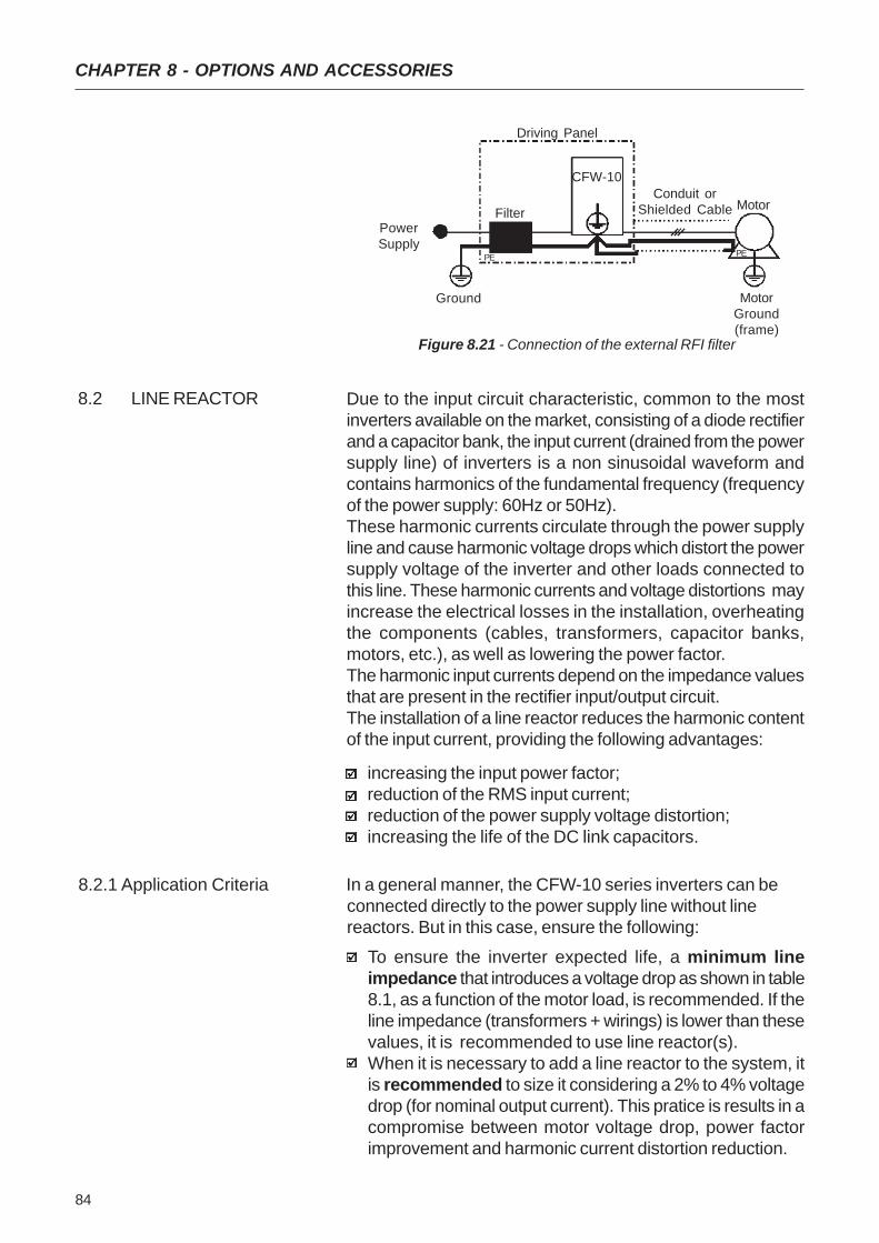
84
CHAPTER 8 - OPTIONS AND ACCESSORIES
8.2.1 Application Criteria In a general manner, the CFW-10 series inverters can beconnected directly to the power supply line without linereactors. But in this case, ensure the following:
To ensure the inverter expected life, a minimum lineimpedance that introduces a voltage drop as shown in table8.1, as a function of the motor load, is recommended. If theline impedance (transformers + wirings) is lower than thesevalues, it is recommended to use line reactor(s).When it is necessary to add a line reactor to the system, itis recommended to size it considering a 2% to 4% voltagedrop (for nominal output current). This pratice is results in acompromise between motor voltage drop, power factorimprovement and harmonic current distortion reduction.
8.2 LINE REACTOR Due to the input circuit characteristic, common to the mostinverters available on the market, consisting of a diode rectifierand a capacitor bank, the input current (drained from the powersupply line) of inverters is a non sinusoidal waveform andcontains harmonics of the fundamental frequency (frequencyof the power supply: 60Hz or 50Hz).These harmonic currents circulate through the power supplyline and cause harmonic voltage drops which distort the powersupply voltage of the inverter and other loads connected tothis line. These harmonic currents and voltage distortions mayincrease the electrical losses in the installation, overheatingthe components (cables, transformers, capacitor banks,motors, etc.), as well as lowering the power factor.The harmonic input currents depend on the impedance valuesthat are present in the rectifier input/output circuit.The installation of a line reactor reduces the harmonic contentof the input current, providing the following advantages:
increasing the input power factor;reduction of the RMS input current;reduction of the power supply voltage distortion;increasing the life of the DC link capacitors.
PowerSupply
Ground
Filter
CFW-10
Driving Panel
Conduit orShielded Cable Motor
MotorGround(frame)
PE PE
Figure 8.21 - Connection of the external RFI filter

85
CHAPTER 8 - OPTIONS AND ACCESSORIES
Table 8.1 - Minimum line impedance for several load conditions.
Note: These values ensure a life of 20,000 hour for the DC link capacitors,i.e., they can be operated during 5 years with operation of 12 hours perday.
Figure 8.2 - Power connection with line reactor at the input
Always add a line reactor, when capacitors for power factorcorrection are installed in the same line and near to theinverter.Figure 8.2 shows the line reactor connection to the input.Use the following equation to calculate the value of the linereactor necessary to obtain the desired percentage of thevoltage drop:
where: Δ V - desired line voltage drop, in percentage (%);Ve - phase voltage at inverter input (line voltage), given in
Volts (V);Is,nom - output inverter rated current (refer to Chapter 9);f - line frequency.
L = 1592 . Δ V . Ve [μH] (f . Ie, nom)
LINE
L/L1
PEPE UVW
SHIELD
Q1
N/L2 U V W PE
N/L2
L/L1
Model
1,6A / 200-240V2,6A / 200-240V4,0A / 200-240V7,3A / 200-240V1,6A / 110-127V2,6A / 110-127V4,0A / 110-127V
Rated load at inverter output(IS = IS, nom)
0,5%0,5%0,5%1,0%1,0%2,0%1,5%
Minimum Line Impedance
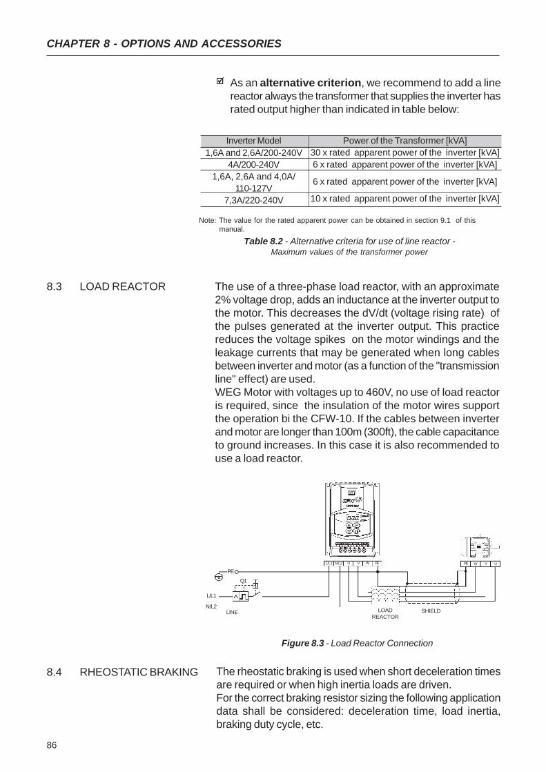
86
CHAPTER 8 - OPTIONS AND ACCESSORIES
The use of a three-phase load reactor, with an approximate2% voltage drop, adds an inductance at the inverter output tothe motor. This decreases the dV/dt (voltage rising rate) ofthe pulses generated at the inverter output. This practicereduces the voltage spikes on the motor windings and theleakage currents that may be generated when long cablesbetween inverter and motor (as a function of the "transmissionline" effect) are used.WEG Motor with voltages up to 460V, no use of load reactoris required, since the insulation of the motor wires supportthe operation bi the CFW-10. If the cables between inverterand motor are longer than 100m (300ft), the cable capacitanceto ground increases. In this case it is also recommended touse a load reactor.
8.3 LOAD REACTOR
As an alternative criterion, we recommend to add a linereactor always the transformer that supplies the inverter hasrated output higher than indicated in table below:
Inverter Model1,6A and 2,6A/200-240V
4A/200-240V1,6A, 2,6A and 4,0A/
110-127V7,3A/220-240V
Power of the Transformer [kVA]30 x rated apparent power of the inverter [kVA]6 x rated apparent power of the inverter [kVA]
6 x rated apparent power of the inverter [kVA]
10 x rated apparent power of the inverter [kVA]
Note: The value for the rated apparent power can be obtained in section 9.1 of thismanual.
Table 8.2 - Alternative criteria for use of line reactor -Maximum values of the transformer power
Figure 8.3 - Load Reactor Connection
LINE
L/L1
PEPE UVW
SHIELD
Q1
N/L2 U V W PE
N/L2
L/L1
LOADREACTOR
The rheostatic braking is used when short deceleration timesare required or when high inertia loads are driven.For the correct braking resistor sizing the following applicationdata shall be considered: deceleration time, load inertia,braking duty cycle, etc.
8.4 RHEOSTATIC BRAKING

87
CHAPTER 8 - OPTIONS AND ACCESSORIES
In any case, the RMS current capacity and the maximum peakcurrent shall be respected.The maximum peak current defines the minimum resistancevalue (ohms) of the braking resistor. Refer to table 8.3.The DC Link voltage level at which the rheostatic braking isactivated is the following:
- CFW-10 200-240V models – 366V DC- CFW-10 110-127V models – 411V DC
The braking torque that can be achieved through theapplication of frequency inverters, without using the rheostaticbraking module, varies from 10% to 35% of the motor ratedtorque.During the deceleration, the kinetic energy of the load isregenerated to the DC Link (intermediary circuitry). Thisregenerated energy charges the capacitors at the intermediarycircuitry increasing the voltage level at the DC Link. In casethis additional energy is not dissipated, an overvoltage error(E01) may occur disabling the inverter.In order to have higher braking torques the rheostatic brakingis applied. When using the rheostatic braking, the additionalregenerated energy is dissipated in an external resistor. Thebraking resistor power is a function of the deceleration time,the load inertia and the resistive torque.Use WIRE or RIBBON resistors in ceramic case withappropriated insulation voltage to withstand a highinstantaneous power (respecting to the rated power).
8.4.1 Sizing
Table 8.3 - Recommended braking resistors
CFW-10Model
1,6A/200-240V2,6A/200-240V4,0A/200-240V7,3A/200-240V1,6A/110-127V2,6A/110-127V4,0A/110-127V
VMáx
(MaximumResistorVoltage)
410 V
460V
MaximumRMS
BrackingCurrent
10 A
5 A
RecommendedResistor
39 Ω
39 Ω
RecommendedWiring
2,5 mm2 / 14 AWG
2,5 mm2 / 14 AWG
MaximumBrackingCurrent
11 A
12A
Prms
(ResistorMaximumPower)
3,9 kW
2,2 kW
Braking not available
Pmax(Resistor
PeakPower)
4,3 kW
5,4 kW
Braking not available
NOTE!Data presented in table 8.3 were calculated for the maximumpower admissible for the frequency converter. For smallerbraking power, another resistor can be used according to theapplication.
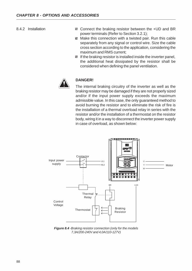
88
CHAPTER 8 - OPTIONS AND ACCESSORIES
Connect the braking resistor between the +UD and BRpower terminals (Refer to Section 3.2.1);Make this connection with a twisted pair. Run this cableseparately from any signal or control wire. Size the cablecross section according to the application, considering themaximum and RMS current;If the braking resistor is installed inside the inverter panel,the additional heat dissipated by the resistor shall beconsidered when defining the panel ventilation.
DANGER!The internal braking circuitry of the inverter as well as thebraking resistor may be damaged if they are not properly sizedand/or if the input power supply exceeds the maximumadmissible value. In this case, the only guaranteed method toavoid burning the resistor and to eliminate the risk of fire isthe installation of a thermal overload relay in series with theresistor and/or the installation of a thermostat on the resistorbody, wiring it in a way to disconnect the inverter power supplyin case of overload, as shown below:
8.4.2 Installation
Figure 8.4 -Braking resistor connection (only for the models7,3A/200-240V and 4,0A/110-127V)
Motor
Input powersupply
Contactor
ControlVoltage
ThermalRelay
Thermostat BrakingResistor
U
V
W
L/L1
N/L2
BR +UD

89
CHAPTER 9
TECHNICAL SPECIFICATIONSThis chapter describes the technical specifications (electricaland mechanical) of the CFW-10 inverter series.
9.1 POWER DATA AC Input Specifications:Voltage: -15%, +10% (with loss of motor efficiency)Frequency : 50/60Hz (± 2 Hz)Overvoltage: Category III (EN 61010/UL 508C)Transient voltages according to Category III.
Minimum line impedance: variable according to invertermodel. Refer to Section 8.2.Power-up: max. 10 ON/OFF cycles per hour.
9.1.2 Power Supply: 110-127V Model: Current/Voltage(V)
Power (kVA) (1)
Rated Output |Current (A) (2)
Max. Output Current (A) (3)
Power Supply
Rated Input Current (A)Switching Frequency (kHz)Max. Motor Power (cv) (4) (5)
Dynamic BrakingWatt Losses (W)Dimensions(Height x Width x Depth)Rheostatic Braking
1.6/ 110-127
0.61.62.4
7.110
0.25HP/0.18kW
40
2.6/ 110-127
1.02.63.9
11,510
0.5HP/0.37kW
45
9.1.1 Power Supply: 200-240V
132 x 95 x 121 mm
Model: Current(A)/Voltage(V)
Power (kVA) (1)
Rated Output Current (A) (2)
Max. Output Current (A) (3)
Power Supply
Rated Input Current (A)Switching Frequency (kHz)
Max. Motor Output (cv) (4) (5)
Watt Losses (W)Dimensions(Height x Width x Depth)Rheostatic Braking
1.6/200-240
0.61.62.4
3.510
0.25HP/0.18kW
30
2.6/200-240
1.02.63.9
5.710
0.5HP/0.37kW
35
4.0/200-240
1.54.06.0
8,810
1HP/0.75kW
50
132 x 95 x 121 mm
Single-Phase
7.3/200-240
2.87.311
165
2HP/1.5kW
901.61x115x112mm
yesno no no
Single-Phase
4.0/100-127
1.54.06.0
17.710
1HP/0.75kW
601.61x115x112mm
yesno no
90
CHAPTER 9 - TECHNICAL SPECIFICATIONS
The values shown in the table were calculated by consideringthe rated inverter current, input voltage of 220V.
(2) Rated current is valid for the following conditions: Relative air humidity: 5% to 90%, non condensing. Altitude: 1000m (3300ft), up to 4000m (13200ft) with 1% derating each 100m (330ft) of the rated current. Ambient temperature: 0ºC to 50º C (32ºF to 122ºF). The rated current values are valid for the switching frequencies of 2.5kHz or 5kHz (factory setting= 5kHz). For higher switching frequencies, 10kHz to 15kHz, consider the values shown in the description of the parameter P297(refer to chapter 6).
(3) Maximum Current: Inverter supports an overload of 50% (maximum output current = 1.5 x the rated output current) during 1 minute for each 10 minutes of operation. For higher switching frequencies, 10kHz to 15kHz, consider the values shown at the description of the parameter P297(refer to chapter 6).
(4) The indicated motor power ratings are only orientative valuesfor IV-pole motors and normal duty loads. The precise in-verter sizing must consider the actual motor nameplateand application data.
(5) WEG inverters are supplied with parameter settings forWEG IV pole standard motors, 60 Hz, 220V and outputsas indicated above.
NOTE!(1) The power rating in VA is determined by the following
equation:
P(kVA)= 3 . Voltage (V) . Current (A)
1000

91
CHAPTER 9 - TECHNICAL SPECIFICATIONS
9.2 ELECTRONIC/GENERAL DATA
Applied Voltage V/F (scalar)
0 to 300Hz, resolution: 0,01Hz.
Speed regulation: 1% of the rated speed.1 isolated input, resolution: 7 bits, (0 to 10)V or (0 to 20)mA, or(4 to 20)mAImpedance: 100kΩ [(0 to 10)V], 500 [(0 to 20)mA or(4 to 20)mA], programable function4 isolated digital inputs, 12V dc, programmable functions1 relay with reverse contacts, 240V ac, 0.5A, programmable
functionsOvercurrent/output short-circuitUndervoltage and overvoltage at the power partInverter overtemperatureMotor/inverter overload (IxT)External faultProgramming errorDefective inverter4 keys: start, stop, increment, decrement and Programming,LEDs display: 3 digits with 7 segmentsLEDs for Parameter and its Contecnt IndicationIt permits access/alteration of all parametersDisplay accuracy:
- current: 10% of the rated current- Voltage resolution: 1 V- frequency resolution: 0,1HzFor all models
Inverters and semicondutorsPower Conversion EquipmentElectronic equipment for use in power installationsSafety requirements for electrical equipment for measurement,control and laboratory useEMC product standard for adjustable speed electrical power drivesystems, with external filter
METHODCONTROL OUTPUT
FREQUENCYPERFORMANCE V/F Control
INPUTS ANALOG(CC10 Board)
DIGITALOUTPUT RELAY
(CC10 Board)
SAFETY PROTECTION
KEYPAD STANDARD HMI (HMI)
DEGREE OF IP20PROTECTION
IEC 146UL 508 C
STANDARDS EN 50178
EN 61010
EN 61800-3
92
WARRANTY
WEG warrants its Frequency Inverters against defects inworkmanship and materials under the following conditions:
1.0 For the effectiveness of this warranty it is essential that thepurchaser inspects carefully the purchased inverter,immediately after receipt, checking its characteristics andfollowing its installation, adjustments, operation andmaintenance instructions. The inverter will be consideredas accept and approved automatically by the purchaser,when the purchaser does not give written notice within max.five days after the receipt of the product about verified non-conformities.
2.0 The warranty period is for twelve months from the invoicedate of the equipment issued by WEG or its authorizeddistributor, proved through equipment invoice, but limitedto twenty four months from the manufacturing date, that isindicated on the product nameplate.
3.0 In case the inverter fails to function or operate incorrectlyduring the warranty time, the warranty services will becarried out, at WEG discretion, at its Authorized RepairShops.
4.0 The failed product must be available to the supplier for arequired period to detect the cause of the failure and tomake the corresponding repairs.
5.0 WEG Automação, or its Authorized Repair Shops willanalyze the returned inverter and when the existence ofthe failure covered by the warranty is proved, it will repair,modify or replace, at its discretion, the defective inverterwithout cost to the purchaser, except as indicated in Item7.0.
6.0 The present warranty responsibility is limited only to repairs,changes or replacement of the supplied inverter. WEG willhave no obligation or liability whatsoever to people, thirdparties, other equipment or installations, including withoutlimitation, any claims for loss of profits, consequentialdamages or labor costs.
WARRANTY TERMS FORCFW-10 FREQUENCYINVERTERS
CHAPTER 10
93
WARRANTY
7.0 Other expenses as freights, packing, disassembling/assembling and parameter setting costs will be paidexclusively by the purchaser, including all fees, ticket,accommodation and meals expenses for technicalpersonnel, when needed and/or requested by thecustomer.
8.0 The present warranty does not cover the normal wear ofthe product or equipment, neither damages resultingfrom incorrect or negligent operation, incorrect parametersetting, improper maintenance or storage, operation outthe technical specification, bad installation quality, oroperated in ambient with corrosives gases or with harmfulelectrochemical, electrical, mechanical or atmosphericinfluences.
9.0 This warranty does not cover parts or components that areconsidered consumer goods, such as rubber or plasticparts, incandescent bulbs, fuses, etc.
10.0 This warranty will be cancelled automatically, independentlyof any previous written notice or not, when the purchaser,without previous written authorization by WEG, makes orauthorized third parties to make any changes or repair onthe product or equipment that failed during the warrantyperiod.
11.0 Repairs, changes, or replacements due to manufacturingdefects will not stop nor extend the period of the existingwarranty.
12.0 Any request, complaint, communication, etc. related to theproduct under warranty, servicing, start-up, etc., shall besent in writing to WEG Branch or Representative.
13.0 The Warranty granted by WEG is conditioned by theobservation of this warranty that is the only valid warrantyfor the good.