cap-XX APPLICATION NOTE No. 1003svc082.wic031v.server-web.com/resources/app_notes/an1003.pdf ·...
27
cap-XX APPLICATION NOTE No. 1003 The Supercapacitor Solution to GPRS and Other Pulsed Loads on CompactFlash and PC Cards Revision 1.0, December 2002 Outline CompactFlash and PC Card products are now being designed with pulsed-load subsystems, such as GPRS and GSM modules. These subsystems frequently require peak currents that exceed the level allowed by the CF Card specification for CF+ devices or the PC Card specification. A cap-XX supercapacitor is a solution to providing the peak power while keeping the current drawn from the host within specification. This application note describes simple host equivalent circuits, power-up and charging of the supercapacitor, voltage ripple and peak current demand, some of the relevant equations, and a spreadsheet tool available from cap-XX to assist with modelling and development work. The Problem The CompactFlash specification allows a CF+ card to draw only 0.5A (maximum average RMS current) and this may be drawn only after switching to Power Level 1. On power-up, the card must operate in Power Level 0, in which it must not exceed 75mA at 3.3V, or 100mA at 5V, if it is to meet the specification. The PC Card specification (Release 8) allows a PC Card to draw the following currents from V CC , when operating at 5V (minimum 4.75V): 0.66A peak (averaged over any 10ms period) and 0.5A average (averaged over any 1s period). If the host supports it, then when operating at 3.3V (minimum 3.0V), the card may draw 1A peak (averaged over any 10ms period) and 0.75A average (averaged over any 1s period). Typical GPRS and GSM transmitters require much higher currents than the peak values allowed by the specifications above. Therefore, if the load is to function correctly, then the card must be able to store much of the energy required by the load and recharge itself between load pulses, so that it presents a smoothed load to the host. See References 2 and 3. A low-ESR (equivalent series resistance) cap-XX supercapacitor can store the energy needed by the load and deliver it on demand. However, it needs to be charged on power-up once the PC or CF card has been set at the correct power level. This can overload the host if charging is not controlled. In certain applications, if the load draws a particularly high current, there may also be a requirement to dynamically limit the current drawn from the host during operation. The card therefore needs a means of controlling the start-up operations, the charging of the supercapacitor, and any current-limiting required during operation. The cap-XX Solution Circuit Configuration A cap-XX supercapacitor across the power supply provides the solution to delivery of a high-power pulse. Relatively simple circuits can provide the solution to charging the supercapacitor at the right time and at the right rate, so that the host device is not overloaded. These are described in more detail below. The card may also incorporate a DC-DC converter, which may be necessary if the load needs to operate at a different voltage from that provided by the host, or if the load voltage has stability requirements that can only be met with a regulated output.
Transcript of cap-XX APPLICATION NOTE No. 1003svc082.wic031v.server-web.com/resources/app_notes/an1003.pdf ·...

cap-XX APPLICATION NOTE No. 1003
The Supercapacitor Solution to GPRS and Other Pulsed Loads on CompactFlash and PC Cards
Revision 1.0, December 2002 Outline CompactFlash and PC Card products are now being designed with pulsed-load subsystems, such as GPRS and GSM modules. These subsystems frequently require peak currents that exceed the level allowed by the CF Card specification for CF+ devices or the PC Card specification. A cap-XX supercapacitor is a solution to providing the peak power while keeping the current drawn from the host within specification. This application note describes simple host equivalent circuits, power-up and charging of the supercapacitor, voltage ripple and peak current demand, some of the relevant equations, and a spreadsheet tool available from cap-XX to assist with modelling and development work. The Problem The CompactFlash specification allows a CF+ card to draw only 0.5A (maximum average RMS current) and this may be drawn only after switching to Power Level 1. On power-up, the card must operate in Power Level 0, in which it must not exceed 75mA at 3.3V, or 100mA at 5V, if it is to meet the specification. The PC Card specification (Release 8) allows a PC Card to draw the following currents from VCC, when operating at 5V (minimum 4.75V): 0.66A peak (averaged over any 10ms period) and 0.5A average (averaged over any 1s period). If the host supports it, then when operating at 3.3V (minimum 3.0V), the card may draw 1A peak (averaged over any 10ms period) and 0.75A average (averaged over any 1s period). Typical GPRS and GSM transmitters require much higher currents than the peak values allowed by the specifications above. Therefore, if the load is to function correctly, then the card must be able to store much of the energy required by the load and recharge itself between load pulses, so that it presents a smoothed load to the host. See References 2 and 3. A low-ESR (equivalent series resistance) cap-XX supercapacitor can store the energy needed by the load and deliver it on demand. However, it needs to be charged on power-up once the PC or CF card has been set at the correct power level. This can overload the host if charging is not controlled. In certain applications, if the load draws a particularly high current, there may also be a requirement to dynamically limit the current drawn from the host during operation. The card therefore needs a means of controlling the start-up operations, the charging of the supercapacitor, and any current-limiting required during operation. The cap-XX Solution Circuit Configuration A cap-XX supercapacitor across the power supply provides the solution to delivery of a high-power pulse. Relatively simple circuits can provide the solution to charging the supercapacitor at the right time and at the right rate, so that the host device is not overloaded. These are described in more detail below. The card may also incorporate a DC-DC converter, which may be necessary if the load needs to operate at a different voltage from that provided by the host, or if the load voltage has stability requirements that can only be met with a regulated output.

cap-XX Application Note 1003 The Supercapacitor Solution to GPRS and Other Pulsed Loads on CompactFlash and PC Cards Rev. 1.0 Dec. 2002
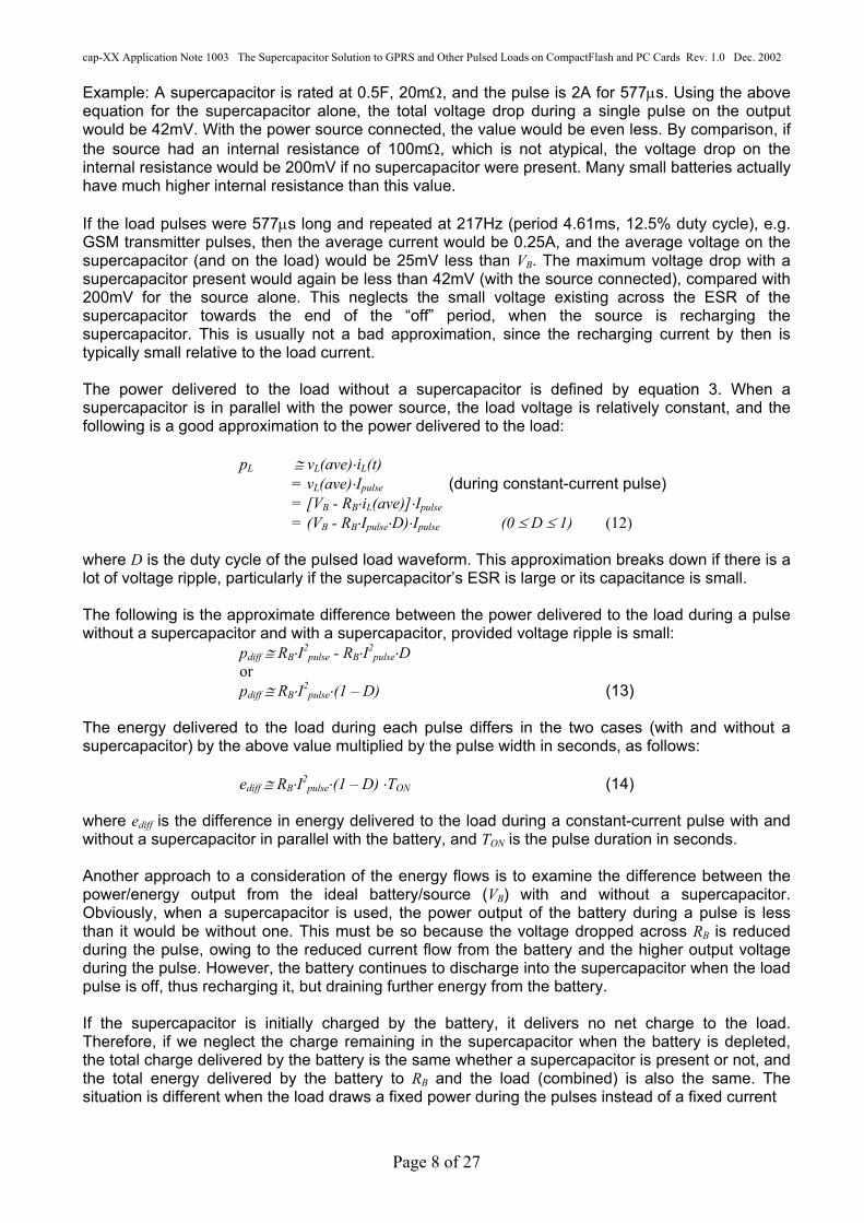
The power supply from the host device is assumed to conform to the CF Card or PC Card specification. It can be regarded as having one of the equivalent circuits in Figure 1.
+VCC +VCC
+ CF Card: 3.135V–3.465V (3.3V ± 5%) @ 0-75mA/500mA or4.5V–5.5V (5V ± 10%) @ 0-100mA/500mA PC Card: 2.97V-3.63V (3.3V ± 10%) @ 0-70mA/500mA/750mA/1000mA or 4.75V-5.25V (5.0V ± 5%) @ 0-100mA/500mA/750mA/1000mA
+
CF Card: 3.3V @ 0-75mA/500mA or 5.0V @ 0-100mA/500mA PC Card: 3.3V @ 0-70mA/500mA/750mA/1000mA or5.0V @ 0-100mA/330mA/500mA/660mA
Z Figure 1 Power Source Equivalent Circuits The circuit on the left in Figure 1 is known as the Thevenin equivalent circuit representing a linear circuit that has a particular open-circuit voltage and a known short-circuit current (or a known, reduced output voltage at a known current). It is often more useful than the circuit on the right, although both have advantages. The voltages and currents shown were taken from the relevant CF Card (CF+) and PC Card specifications. The current values for a CF Card refer to the low-power ‘Power Level 0’ state and the higher ‘Power Level 1’ state that applies only to CF+ devices. The current values for a PC Card refer to the card-configuration current (the lowest value), the static current, the average current and the peak current (as given in Release 8 of the specification). Note that some older PC Card host devices that may still be in use could supply 5V to the card and not 3.3V, even if the card is configured for 3.3V. The impedance, Z, in Figure 1 is typically assumed to be a resistor. Its value (R) is usually calculated from the values of the open-circuit and loaded output voltages, for a known load current, as follows:
R = (VCC,Open – VCC,Loaded)/ILoad (1)
To use equation 1, a load is imposed that is not excessive for the source, and the voltage under load (VCC,Loaded) is measured. The circuit on the right in Figure 1 represents a simple voltage source that has a range of outputs that depends on the load, the time at which the load current is applied (on power-up or later) and on whether the host system supplies 5V or 3.3V. The approximate maximum values of the Thevenin source impedance, Z, can be calculated from the values given in the specification. For a CF card at 3.3V, it is
R = (3.465 – 3.135)/0.5 = 0.66Ω (Power Level 1)
For a CF card at 5V, the approximate maximum source impedance is
R = (5.5 – 4.5)/0.5 = 2Ω (Power Level 1)
In practice, the source impedance of the PC Card or CF Card power supply is considerably less than the maximum values. Source impedances in the range of 100mΩ - 200mΩ are typical. Figure 2 shows a basic power system in which a supercapacitor is connected in parallel with the supply. The supercapacitor is represented by a simple model consisting of its capacitance, C, in series with its ESR, RC. (Note that this is not an added resistor; the resistance in the supercapacitor connection should be kept as low as possible in all circuits.) The supply is modelled as a voltage source, VCC (or VB), in series with its source resistance, R.
Page 2 of 27

cap-XX Application Note 1003 The Supercapacitor Solution to GPRS and Other Pulsed Loads on CompactFlash and PC Cards Rev. 1.0 Dec. 2002
When the device is first connected to the supply (the host) with a discharged supercapacitor, the supercapacitor’s low ESR and high C can result in a large current being drawn from the supply. The current-limiter block represents a circuit that charges the supercapacitor without violating the power-drain specifications of the host device. This circuit may also limit the current during normal use, if high load pulses would otherwise make the card exceed the maximum current allowed. The current-limiter circuit will include components, such as a MOSFET, that add to the series resistance of the circuit; for modelling purposes, this resistance may be added to that of the supply’s source impedance. The current-limiter may have a control input that tells it when to start charging the supercapacitor and possibly also when to turn off supply to the supercapacitor. This control signal would be under the control of the software running on the card. E.g., in a CF card it could activate the current-limiter when the host device permitted the card to go to Power Level 1. For further information on current-limiting circuits, see References 1 and 4. The circuit in Figure 2 would typically be chosen as a low-cost implementation. Refer to reference 1 for examples of such a circuit. Figure 7 shows a simulation of waveforms in a PC Card circuit of this type transmitting a class 10 GPRS signal. Note that the low ESR and high C of the supercapacitor result in a small ripple voltage, which is well under the 300mV – 400mV maximum allowed by the specifications of many GPRS modules. If the current drawn by the load during pulses is so high that current-limiting is necessary during operation even with the supercapacitor present, then a current-limit circuit that is always operational is needed, as opposed to a current-limit circuit that only limits the current during power-up. Note that the current limit reduces the average voltage at the supercapacitor to less than the output voltage of the supply. However, provided there is sufficient average current and no limiting between load pulses, the low ESR and high C of the supercapacitor maintain the minimum voltage to the RF power amplifier module, and the voltage ripple is less than the maximum allowed at the power input to the module.
Control
CURRENT-LIMITER
+ VCC (or VB)
PULSED LOAD
R
C Supercapacitor
RC (ESR)
Figure 2 Basic Power System With Supercapacitor Figure 3 is a power system in which a DC-DC converter is used to increase the flexibility of the system. It could be a buck or boost converter, depending on the requirements of the load. This circuit would be selected when the load must be able to operate at a voltage that is substantially different to the source voltage, for example, with GPRS modules whose maximum VCC or VBatt is 4.5V but minimum VCC or VBatt during transmission is 3.3V. This means their operating voltage range is too low for the 5V rail (maximum 5.5V on a PC card, or 5.25V on a CF card) and too high for the 3.3V rail (minimum 2.97V on a PC card, or 3.135V on a CF Card).
Page 3 of 27

cap-XX Application Note 1003 The Supercapacitor Solution to GPRS and Other Pulsed Loads on CompactFlash and PC Cards Rev. 1.0 Dec. 2002
Control
CURRENT-LIMITER
DC-DC CONVERTER& CURRENT-
LIMITER
Control+ VCC (or VB)
PULSED LOAD
R
C Supercapacitor
RC (ESR)
Figure 3 Power System With DC-DC Converter and Supercapacitor For example, if the load requires a low voltage, such as 3.3V, a buck converter with current-limited output may be used to reduce a 5V input to 3.3V. When the input is 3.3V, the converter would be bypassed and the current-limiter circuit would be used to charge the supercapacitor and supply the load. The current-limiter would only be required to limit the current during normal operation if not doing so resulted in the current drawn from the host exceeding the allowed value. As this would depend on the source impedance of the host, it may be necessary to test the card in the relevant conditions and/or simulate the circuit. If the load in Figure 3 requires a higher voltage, such as 4.5V, a boost converter with current-limited output may be used to boost 3.3V to the required level. To operate from a 5V input, the boost converter would be bypassed and the load would be supplied by the current-limiter, which would incorporate a LDO (low drop-out) regulator to prevent the output exceeding either the supercapacitor’s or the load’s rated voltage. The control signals would activate either the current-limiter or the DC-DC converter, depending on the value of the input voltage. This would be under software control and would occur when the host permitted the card to change to Power Level 1. The configuration in Figure 3 has the advantage that the supercapacitor can supply most (or all) of the load pulse, so the DC-DC converter need only be capable of supplying the average load current plus losses. The power MOSFETs and the inductor in the DC-DC converter can therefore be much smaller than they would need to be to supply the peak current. In Figure 3, the output of the DC-DC converter must be current-limited, so that the supercapacitor supplies most of the peak current and the DC-DC converter does not overload the host during load pulses. Without current-limiting, the DC-DC converter will try to maintain the voltage at its output (assuming the source can supply sufficient current), and not enough current will be drawn from the supercapacitor. (For any capacitor, the current flow in or out is i = C(dv/dt); i.e., there has to be a change in voltage for it to supply any current. With a high-C supercapacitor, this voltage change does not have to be large for it to provide a substantial current.) Figure 4 shows a configuration that may be advantageous when the load requires a very stable
RC (ESR)
C Supercapacitor
R
PULSED LOAD
+ VCC (or VB)
CURRENT-LIMITER
DC-DC CONVERTER
Control Control
Figure 4 Power System With Stable DC-DC Converter Output and Supercapacitor Page 4 of 27

cap-XX Application Note 1003 The Supercapacitor Solution to GPRS and Other Pulsed Loads on CompactFlash and PC Cards Rev. 1.0 Dec. 2002
supply voltage, and/or when the load voltage must be different to the input voltage, and/or when the peak current must be maintained for so long that the supercapacitor voltage would drop below the minimum voltage the load requires. The current-limiter charges the supercapacitor, which supplies the DC-DC converter. The stability of the load voltage is therefore determined by the DC-DC converter. The supercapacitor voltage may be allowed to drop significantly during load pulses, provided it does not drop below the minimum required by the DC-DC converter. The current-limiter ensures that the host is not overloaded during initial charging of the supercapacitor and, if necessary, during operation. If the benefits justify it, the current-limiter may be a DC-DC converter that is capable of operating as a current-limiter. This option depends on whether sufficient space is available if this provides sufficient additional efficiency to justify it. (If limiting during normal operation is necessary, then the designer will need to compare the efficiency of a DC-DC converter acting as a limiter, which may be 80%-90+%, with that of a linear limiter that has a voltage drop across it at least for some of the time.) A disadvantage of the Figure 4 configuration is that the DC-DC converter has to be able to provide the full peak current required by the load, which increases the sizes of the MOSFETs and inductor over those required for the configuration of Figure 3. Refer to the cap-XX Application Note 1002, Start-Up Current-Limiters for Supercapacitors in PDAs and Other Portable Devices, for more information on current-limiting circuits. Circuit Design and Modelling
Introduction A useful tool for modelling pulsed-load circuits is a spreadsheet developed by cap-XX that can be downloaded free-of-charge from its web site. (See URL at the end of this document.) The version on the web site is in two parts, one of which is designed to simulate loads that draw a fixed current during the pulse, and the other for loads that draw a fixed power during the pulse. The latter type of load dynamically increases the current drawn from the supply as the voltage drops, which can be an important characteristic of some loads that need to output a certain power. These simulator spreadsheets can be used as a design aid and to get an indication of whether a circuit will behave within specification. SPICE simulations of a proposed design may also be very helpful. Figure 5 is the equivalent circuit of the power source (which could be a battery) and the supercapacitor. The load is shown as a pulse of either a given current or a given power that is imposed at a given frequency. In order to make sure the system meets a specification, it is necessary to be able to determine the peak current drawn from the source.
iLiciB
CSource, e.g. Battery
RB RC (ESR)
vL Fixed-Current or Fixed-Power Load i or p
+VB+vc
Figure 5 Simple Equivalent Circuit of Power Source and Supercapacitor Subjectedto Pulsed Load
Page 5 of 27

cap-XX Application Note 1003 The Supercapacitor Solution to GPRS and Other Pulsed Loads on CompactFlash and PC Cards Rev. 1.0 Dec. 2002
Fixed-Current Pulse In a circuit in which there is no supercapacitor (C) in parallel with the battery, the open-circuit (no-load) voltage of the system is VB. The voltage under load is given by the following:
BLBL RiVv −= (2) If a load pulse of a certain current is drawn with no supercapacitor connected, the power delivered to the load is given by the following:
)(])([)( tiRtiVtp LBLBL ⋅−= (3a) pulseBpulseB IRIV ][ −= (during load pulse) (3b)
This is the difference between the power delivered by the source (battery or power supply) and the losses in its internal resistance. Placing a low-ESR supercapacitor in parallel with the battery can greatly reduce the amount of voltage drop during load pulses. This increases the power delivered to the load. The charge (in Coulombs) drawn from the battery by each load pulse depends only on the current and the pulse duration, not on the battery voltage. The voltage on the ideal “internal” battery, excluding the internal resistance, remains unchanged during the pulse. If the internal resistance behaved in all respects like a real resistor, including dissipating power when carrying current, then the battery would be delivering the same energy in total, where the “load” is considered to include its own internal resistance. Obviously, the energy delivered to the real load would then be reduced by the amount lost in the internal resistance. The actual behaviour of the internal resistance of a battery may depend on the battery’s chemistry and its design. Consider a system with a supercapacitor in parallel with the power source (as above) that has been left to reach equilibrium for a long time. At equilibrium, with no external load, vC=VB. It can be shown that, for a current pulse that is drawn by a load, the current in the supercapacitor will obey the following equation for the duration of the pulse:
CRRt
eRR
RIti CB
CB
BpulseC
)()( +−
⋅+
= (4)
where Ipulse is the magnitude of the current pulse. This equation applies regardless of the voltage at the voltage source. Obviously, the higher the initial source (or battery) and supercapacitor voltage, the greater will be the energy drawn from the system during the pulse, since the power drawn at any instant is equal to the product of voltage and current. From the above, the initial current in the supercapacitor when the pulse is applied will be as follows:
pulseCB
B IRRRiC +=)0( (5)
The following relationship applies to the currents:
)()()( tititi CLB −= (6) Thus, the current drawn from the power source and the current’s initial value will be defined by the following:
Page 6 of 27

cap-XX Application Note 1003 The Supercapacitor Solution to GPRS and Other Pulsed Loads on CompactFlash and PC Cards Rev. 1.0 Dec. 2002
])([)( CRRt
eRR
RIti CB
CB
CpulseB
+−
⋅+
= (7)
][)0(CB
Cpulse RRRIiB += (8)
If RC is very much smaller than RB, the supercapacitor will provide the majority of the initial current. If C is sufficiently large, then the supercapacitor will continue to provide the majority of the current for the duration of the pulse. Typically, cap-XX supercapacitors are designed to be large enough in most applications to deliver a substantial part of the load current, with the result that there is very little ripple voltage on the load. If the system is in equilibrium before the pulse is applied, then the output (load) voltage obeys the following equation for the duration of the current pulse:
])([)( CRRt
eRR
RRIVtv CB
CB
CBpulseBL
+−
⋅+
⋅−= (9)
This equation shows that the smaller RC is in relation to RB, the smaller will be the initial voltage drop when the load pulse is applied. The larger the value of C, the longer the time constant, (RB+RC)C, and the less will be the voltage droop at the output over the duration of the current pulse. If the current pulses are repeated at regular intervals, it can be shown that the average voltage on the “ideal” supercapacitor, C, (the internal equivalent ideal capacitance) will be equal to the average voltage at the output, as follows:
)()()( aveiRVavevavev LBBLC ⋅−== (10) Note that the greater the duty cycle (or mark-space ratio) of the pulse waveform, the more the average current approaches the maximum (peak) current, and the closer the average voltage gets to the voltage under load of the power source alone. At 100% duty cycle, the average voltage equals the voltage of the battery alone under load. If C is sufficiently large and RC sufficiently small, the fluctuations in voltage on the supercapacitor during the load pulses and the intervals between pulses will be small. The supercapacitor has the effect of a first-order filter on the voltage that is very effective by virtue of its large C and small ESR, thereby smoothing the ripple. (This is also known as load-levelling.) Since the power that can be delivered to the load depends on the output voltage, the supercapacitor enables the system to supply increased power to the load, compared with the ability of the power source alone, by maintaining the voltage level during the load pulses. The voltage drop under load (with a duty cycle under about 0.5) can be significantly reduced by the use of a supercapacitor in parallel with the power source. This is shown by the following equations and example, in which it is assumed that all load current for the duration of the pulse is drawn from the supercapacitor. Adding the supercapacitor’s resistive (ESR) voltage drop and capacitive voltage drop, a rough approximation to the total voltage drop during a pulse is given by the following:
)(C
TRIV ONCpulsedrop += (11)
where TON is the pulse length in seconds. If the power source remains connected to the load during the application of the load pulse(s), then it will assist in maintaining the voltage, and the drop will be less than that given by this equation. In some applications, it may be desirable to disconnect the source during the pulse, as this can assist in isolating other circuits from an electrically noisy load.
Page 7 of 27
cap-XX Application Note 1003 The Supercapacitor Solution to GPRS and Other Pulsed Loads on CompactFlash and PC Cards Rev. 1.0 Dec. 2002
Example: A supercapacitor is rated at 0.5F, 20mΩ, and the pulse is 2A for 577µs. Using the above equation for the supercapacitor alone, the total voltage drop during a single pulse on the output would be 42mV. With the power source connected, the value would be even less. By comparison, if the source had an internal resistance of 100mΩ, which is not atypical, the voltage drop on the internal resistance would be 200mV if no supercapacitor were present. Many small batteries actually have much higher internal resistance than this value. If the load pulses were 577µs long and repeated at 217Hz (period 4.61ms, 12.5% duty cycle), e.g. GSM transmitter pulses, then the average current would be 0.25A, and the average voltage on the supercapacitor (and on the load) would be 25mV less than VB. The maximum voltage drop with a supercapacitor present would again be less than 42mV (with the source connected), compared with 200mV for the source alone. This neglects the small voltage existing across the ESR of the supercapacitor towards the end of the “off” period, when the source is recharging the supercapacitor. This is usually not a bad approximation, since the recharging current by then is typically small relative to the load current. The power delivered to the load without a supercapacitor is defined by equation 3. When a supercapacitor is in parallel with the power source, the load voltage is relatively constant, and the following is a good approximation to the power delivered to the load:
pL ≅ vL(ave)⋅iL(t) = vL(ave)⋅Ipulse (during constant-current pulse) = [VB - RB⋅iL(ave)]⋅Ipulse = (VB - RB⋅Ipulse⋅D)⋅Ipulse (0 ≤ D ≤ 1) (12)
where D is the duty cycle of the pulsed load waveform. This approximation breaks down if there is a lot of voltage ripple, particularly if the supercapacitor’s ESR is large or its capacitance is small. The following is the approximate difference between the power delivered to the load during a pulse without a supercapacitor and with a supercapacitor, provided voltage ripple is small:
pdiff ≅ RB⋅I2pulse - RB⋅I2
pulse⋅D or pdiff ≅ RB⋅I2
pulse⋅(1 – D) (13) The energy delivered to the load during each pulse differs in the two cases (with and without a supercapacitor) by the above value multiplied by the pulse width in seconds, as follows:
ediff ≅ RB⋅I2pulse⋅(1 – D) ⋅TON (14)
where ediff is the difference in energy delivered to the load during a constant-current pulse with and without a supercapacitor in parallel with the battery, and TON is the pulse duration in seconds. Another approach to a consideration of the energy flows is to examine the difference between the power/energy output from the ideal battery/source (VB) with and without a supercapacitor. Obviously, when a supercapacitor is used, the power output of the battery during a pulse is less than it would be without one. This must be so because the voltage dropped across RB is reduced during the pulse, owing to the reduced current flow from the battery and the higher output voltage during the pulse. However, the battery continues to discharge into the supercapacitor when the load pulse is off, thus recharging it, but draining further energy from the battery. If the supercapacitor is initially charged by the battery, it delivers no net charge to the load. Therefore, if we neglect the charge remaining in the supercapacitor when the battery is depleted, the total charge delivered by the battery is the same whether a supercapacitor is present or not, and the total energy delivered by the battery to RB and the load (combined) is also the same. The situation is different when the load draws a fixed power during the pulses instead of a fixed current
Page 8 of 27

cap-XX Application Note 1003 The Supercapacitor Solution to GPRS and Other Pulsed Loads on CompactFlash and PC Cards Rev. 1.0 Dec. 2002
If the instantaneous internal (or open-circuit) voltage on the supercapacitor is vC, the source voltage is VB, the current out of the battery is iB and current out of the supercapacitor is iC, then it can be shown that the following equations describe the dynamic behaviour of the circuit:
CB
BLBCC RR
RiVvi
++−
= (15)
CB
CLCBCLB RR
RivViii
++−
=−= (16)
Cti
v CC
∆⋅−=∆ (17)
where iC is considered positive when current flows out of the supercapacitor, as shown in Figure 5. ∆t is the time step in the simulator. The value of vC at the next time step is given by:
CCC vnvnv ∆+=+ )()1( (18) If a current limit, ILim, is specified and if iB > ILim in the simulation, then iB is set equal to ILim, and vc is calculated as follows:
)( CBLimCLBc RRIRiVv +−+= (19) These equations can be used to create a simulation of the circuit’s response to a given load current, iL, or can be solved analytically to obtain equations describing the response to a given load waveform. They form the basis of the simulator built into the fixed-current pulsed-load simulator spreadsheet available from the cap-XX web site. The following equations define the instantaneous values of the load voltage, the power delivered to the load, the power loss in the internal resistance of the battery and the power loss in the ESR of the supercapacitor:
BBBL RiVv ⋅−= (20)
LLL ivp ⋅= (21)
BBR RipB
⋅= 2 (22)
CcR RipC
⋅= 2 (23) The energy expended or delivered in a time ∆t in any of the above three power relationships is determined from following simple equation:
tpe ∆⋅= (24) At the time the first pulse of a repeated pulsed load is applied, the supercapacitor’s internal voltage is the same as the voltage on the battery, provided the supercapacitor has had sufficient time to charge. With each applied pulse, the voltage on the supercapacitor drops slightly, until its average voltage (in steady-state) reaches the average value given by equation 10.
Page 9 of 27

cap-XX Application Note 1003 The Supercapacitor Solution to GPRS and Other Pulsed Loads on CompactFlash and PC Cards Rev. 1.0 Dec. 2002
T2T1 i2 t
iL, vC vCi1
vC(tX)iL
Figure 6 Determination of Open-Circuit Supercapacitor Voltage at Leading Edge of Fixed-Current Load Pulse
Figure 6 shows a train of load pulses after the supercapacitor has reached steady state. The graphs are the idealised load current (the rectangular wave) and the voltage ripple on the supercapacitor (exaggerated in scale for the sake of clarity). It can be shown that the open-circuit voltage on the supercapacitor at the leading edge of a load pulse in steady-state conditions is given by the following equation:
)()(
2)(
)(
1)(
1221
212
1
)()()(
CB
CBCB
RRCTT
BBRRCTT
BBRRC
T
BXC
e
RiVeVRieiiRtv
++−
++−
+−
−
−+⋅−+⋅−= (25)
The voltage vC(tX) will be different to the voltage observed at the supercapacitor’s terminals by an amount equal to RCiC at the instant of measurement. vc(tX) is the value required for “Vinit Supercap” in the Fixed-Current Pulse Simulator. Examples on the use of the Fixed-Current Pulsed-Load Simulator are included in the section titled Determination of C and ESR Required.
Fixed-Power Pulse Refer again to the equivalent circuit in Figure 5. This discussion deals with a load that requires pulses of power that are essentially constant for the duration of the pulses. The load may be a GSM or GPRS transmitting device for example, or one of many other devices. A computer’s CPU may also present an approximate rectangular power waveform when operating in thermal throttling mode. If the power source is a reasonably fresh battery or a power supply and if there is no supercapacitor present, the voltage will remain relatively constant during each load pulse after the initial voltage drop. However, the initial voltage drop, equal to iLRB (for a battery), will be very much larger than it would be with a supercapacitor present. The current drawn during the pulse remains relatively constant because the power drawn is constant and the voltage is almost constant. If the battery voltage continues to drop during the load pulses, the load will draw increasing current in order to keep the power constant. To simplify the equations, the following approximation may be used: The power to the load is approximately pL = VB iL. The approximate current drawn by the load is
B
B
LB
L
L
LL
RVpV
pvpi
−≈= (26)
In the above equation, the power delivered to the load is reduced by the voltage drop across the internal resistance of the battery. This, in turn, means that the load has to draw an increased current
Page 10 of 27

cap-XX Application Note 1003 The Supercapacitor Solution to GPRS and Other Pulsed Loads on CompactFlash and PC Cards Rev. 1.0 Dec. 2002
in order to receive the required power, hence increasing the current demand over that of an ideal system in which the battery has zero internal resistance. As the output voltage, vL, drops, the current drawn by the load increases, as it must, in order to maintain the required power. The exact relationship between the load current in a system with no supercapacitor and the power required by the load is given by the following equation:
B
BpulseB
L
RRtpVV
ti B
2)(4
)(2 ⋅−±
= (27)
If there is a supercapacitor in parallel with the battery, then the voltage drop under load will be reduced, as discussed before. This has the effect of reducing the current required to deliver the power to the load. This, in turn, assists in reducing the voltage ripple that is already reduced by the presence of a supercapacitor. With a supercapacitor in parallel with the power source, the output voltage under load may be approximated by the average voltage, and this is determined from the average power. For a load pulse of a given power, ppulse, and a given duty cycle, D (0 ≤ D ≤ 1), the average power is the product
pL(ave) = ppulseD (0 ≤ D ≤ 1) (28) If the supercapacitor has a large capacitance and low ESR, the voltage ripple at the load will be small. Then the approximate average battery current required to deliver the above average power with a supercapacitor present is given by the following:
B
B
LB
L
L
LB
RVavepV
avepavevavepavei
)()(
)()()(
−≈≈ (29)
A more accurate expression is the following:
B
BLB
B
RRavepVV
avei B
2)(4
)(2 ⋅−±
≈ (30)
Note that the current in the above equations depends on the average power rather than the peak power drawn in each pulse, resulting in a significant reduction in peak battery current compared to that without a supercapacitor. (This benefit vanishes with very large duty cycles, close to 1.0, as before.) The average voltage at the output with a high-C, low-ESR supercapacitor connected can be approximated by the following:
BBBL RaveiVavev ⋅−≈ )()( (31) As in the case of a fixed-current load, the voltage drop during the pulse with a supercapacitor present is reduced significantly over that with the battery alone. With a supercapacitor connected, the approximate load current during a fixed-power pulse is the following:
Page 11 of 27

cap-XX Application Note 1003 The Supercapacitor Solution to GPRS and Other Pulsed Loads on CompactFlash and PC Cards Rev. 1.0 Dec. 2002
)(avevpI
L
pulsepulse ≈ (32)
The corresponding drop in output voltage under load can again be approximated roughly by the voltage drop when only the supercapacitor supplies the full load current (neglecting the contribution of battery current), as follows:
)(C
TRIV ONCpulsedrop −≈ (33)
If the source remains connected during the pulse, the voltage drop will be less than the value given by this equation. As in the fixed-current case, it may be desirable to disconnect the source from the load and supercapacitor when the load pulse is applied, if the load is electrically noisy. When simulating a fixed-power load in Figure 5 with a sample interval equal to ∆t, it can be shown that the source (battery) current satisfies the following equation involving the load power, P, and ∆t:
02 =+⋅+⋅ BBBBB cibia (34) where
])2
1([ CC
BBB RCR
tRRa +∆
+= (35)
CBC
BBC
BCB RVCRtRV
CRtRvb −+
∆−
∆+= )2()1( (36)
)2(2
)( 22BBCC
CCCBBB VVvv
CRtPRvVVc +−
∆++−= (37)
The solution to the above is given by the following:
B
BBBBB a
cabbi
242 −±−
= (38)
The supercapacitor current may be calculated in terms of iB from the following equation:
C
BBBCc R
RiVvi
)( −−= (39)
If a current limit, ILim, is specified and if iB > ILim in the simulation, then iB is set equal to ILim, and iC is calculated as follows:
C
BLimBCc R
RIVvi
)( −−= (40)
Alternatively, the supercapacitor current may be found directly, in the same way iB was calculated. It can be shown that it satisfies the following equation involving the load power, P:
02 =+⋅+ CCCCC cibia (41) where
Page 12 of 27

cap-XX Application Note 1003 The Supercapacitor Solution to GPRS and Other Pulsed Loads on CompactFlash and PC Cards Rev. 1.0 Dec. 2002
Ct
RR
RaB
CCC 2
)1( ∆++= (42)
CCBB
CC vvV
RR
b −−= )2( (43)
PR
Vvvc
B
BCCC +
−= )( (44)
The supercapacitor current iC is then the solution to the quadratic, as follows:
C
CCCCC a
cabbi
242 −±−
= (45)
The change in the supercapacitor’s voltage by the end of the time interval (∆t) is then found, using the relationship in equation 17, as follows:
Cti
v CC
∆⋅=∆ (46)
The load voltage may be determined from one of the following equations:
BBBL RiVv −= (47) or
CCCL Rivv −= (48) The above equations are used in the Fixed-Power Pulsed-Load Simulator.
Determination of C and ESR Required Once the desired circuit configuration (such those shown in Figures 2, 3 and 4) is decided, the values of the capacitance and ESR of the supercapacitor need to be determined. The main criteria that determine these parameters are the following values: • Minimum battery/source voltage during operation (and maximum voltage, if relevant). • Maximum permitted source current drawn from host. • Minimum load voltage required for correct operation of the load. • Load current/power profile, consisting of pulse period and duty cycle, current/power required
during load pulse, and current/power required during intervals between load pulses. • Maximum permitted ripple in load voltage, if specified. In many applications, there may be a range of values of C and ESR that will enable the load to function. The less demanding the application is, the wider this range is likely to be. The combinations of values that are acceptable may include high C and high ESR through to low C and low ESR (relatively speaking) and, for the most demanding applications, high C and low ESR. High capacitance minimises the voltage droop during the load pulses, while low ESR minimises the voltage drop at the instant the load pulses are applied. In some very demanding applications, the current drawn from the source may be too high even with one of the available low-ESR, high-C supercapacitors. If this is the case, but it appears that the requirements could be met with a supercapacitor with even lower ESR or higher C, then it may be possible to meet the specification by another means. This is to increase the source resistance either
Page 13 of 27

cap-XX Application Note 1003 The Supercapacitor Solution to GPRS and Other Pulsed Loads on CompactFlash and PC Cards Rev. 1.0 Dec. 2002
by using a cheaper MOSFET with increased ON-resistance in the current-limiter circuit, or by adding the right amount of resistance to the power input rail from the source. This additional resistance can help to keep the current drawn from the source during pulses below the maximum value permitted. Care should be taken not to add too much resistance, as this will reduce the average load voltage. Another solution that is more energy-efficient is to use a current-limit circuit that limits the peak current drawn during operation as well as the charging current during power-up (refer to Reference 1). Spreadsheets published by cap-XX for the simulation of fixed-current and fixed-power pulsed loads can be very useful in confirming the minimum C and maximum ESR required in a supercapacitor. (The spreadsheets may be downloaded from the cap-XX web site.) SPICE modelling is also very useful; a simple linear model of the supercapacitor that uses only ESR and C will generally provide acceptable results in most low-frequency applications. The calculation of the approximate values of C and ESR required is simpler for fixed-current loads than it is for fixed-power loads, as the equations are simpler. However, it is usually possible to obtain a good estimate of the values in the fixed-power case by approximation. Both techniques are discussed below. Before attempting to calculate the supercapacitor’s parameters, some basic checking should be done to determine whether the source is capable of supplying the load. Voltage check: If the minimum value of the source voltage is below the minimum at which the load will operate (unless there is a boost converter between the two), then the application is not feasible without boosting the voltage or re-designing the system. Power check: The supercapacitor acts as a first-order low-pass filter on the power supply. This smooths the load and enables one to use average load current or average power as a reasonable approximation to the current or power that will be drawn from the source. However, if the average power required by the load is more than the average power the source can provide, then the application is not feasible at all. If a DC-DC converter is to be used, then its efficiency must be taken into account in this calculation.
In the case of a fixed-current load, the average load current is given by the following:
ContinuousPeakAveL iDiDi )1(, −+⋅= (49) (D is the duty cycle, between 0 and 1, and the continuous current is the worst-case expected average current between pulses during normal operation.) This average current must be less than the average current the source is capable of supplying. In the case of a fixed-power load, the average load power is given by the following:
ContinuousPulseAveL pDpDp )1(, −+⋅= (50) This average load power must be less than the minimum average power that the source can supply, which is given by the product of the minimum voltage the source will provide and the maximum average current that may be drawn from it, as follows:
max,min,min,, BBAveB iVp ⋅= (51) If a DC-DC converter having efficiency η (0 < η < 1) is between the source and load, then the average load power above must be increased, as follows:
))1((1, ContinuousPulseAveL pDpDp −+⋅=
η (52)
Again, this must not exceed pB,min,Ave. If a fixed-current load is driven by a DC-DC converter, then the load current should be converted to load power at the output of the converter, and the input power estimated by dividing by the efficiency; the result can then be compared with the minimum average source power.
Page 14 of 27

cap-XX Application Note 1003 The Supercapacitor Solution to GPRS and Other Pulsed Loads on CompactFlash and PC Cards Rev. 1.0 Dec. 2002
C and ESR required for a fixed-current pulsed load in the circuit in Figure 2: To continue, a copy of the fixed-current supercapacitor pulse-simulator spreadsheet from the cap-XX web site is required. Open the spreadsheet and refer to the documentation worksheet, “Read Me First”, for information on what the simulator does and how to use it. Enter the values in the relevant cells for the source (battery) voltage, source resistance, and pulse width and period. If the current-limiter has significant series resistance, it should be added to the source resistance for the purpose of the simulation. Enter a simulation time somewhere between about one period and 10 periods long; five is a good number. (Simulation time is arbitrary, but it is useful to be able to see more than one period in order to see any trend, and it is not advisable to have too many cycles in the simulation period, as this may result in errors in the simulation resulting from too few simulation steps per pulse.) If suitable values of C and ESR for the supercapacitor are not known, then initial values may be guessed. For example, values of 20mΩ to 100mΩ and 0.25F to 1.5F (respectively) could be reasonable starting points, depending on the application. Enter a value for the continuous current drawn by the load; this is the worst-case average current drawn between load pulses. Enter a value for the pulse current; this is the current drawn during the pulses, excluding the continuous current. (The total current drawn during the pulses will be the sum of the continuous current and the pulse current.) Enter values for the source current limits during pulses and between pulses. The current drawn from the source/battery will be limited to these values during the relevant time intervals. If the current-limiter in Figure 2 operates only while charging the supercapacitor and then permits current of any value to flow, the values of the current limits may be set sufficiently high that there is no limiting action (say a 10A limit for a 2A maximum in a typical GPRS application). The result can then be examined to determine if any specified maximum source current has been exceeded by checking the “Current Limit Exceeded” flag. If the limiter acts during normal operation as well, then the appropriate limits should be entered. There are separate settings for current limits during pulses and between pulses. This is because in some applications the source/battery may be isolated from the load during pulses, to minimise electrical noise in other circuits; this may be simulated by setting the limit during pulses to zero. Enter a value for the initial open-circuit voltage on the supercapacitor. The most useful value is typically the steady-state voltage that would be measured at the leading edge of one of the pulses if the supercapacitor were open-circuit. This steady-state value is calculated by the spreadsheet and displayed in the cell labelled ‘Steady-State Vc’. (This value is correct if no limiting takes place.) If this value is entered as the initial voltage, then the simulation will reflect the circuit’s behaviour in its steady state. (There should then be no difference visible between the voltages on the supercapacitor at the leading edges of all pulses displayed on the chart.) Note: If the initial voltage on the supercapacitor is higher than the steady-state value, then the voltage on the supercapacitor will begin to decay gradually to its steady-state value. If the initial voltage is lower than the steady-state value, then it will gradually increase to that value. Users should be aware that it might take a long time to reach the steady state, even though the load voltage for the duration of the simulation may not appear to be changing very much. If limiting takes place, then the calculated value of ‘Steady-State Vc’ will be incorrect. In this case, the user should iterate to a solution by reading the value of ‘Vinit Supercap’ from the last pulse in the simulation (shown as Vc(tx) in Figure 6) and using this as the new value of ‘Vinit Supercap’ in the table of entries (i.e., the value used for the first pulse). Repeat this process until the value of Vinit supercap read from the simulation graph for the last pulse is approximately the same as the value for the first pulse. After all the above values have been entered, the simulation will update itself to display the result. It is then possible to examine the load voltage and determine whether it remains within the range in which the load will function. The source current may also be checked to determine whether it
Page 15 of 27

cap-XX Application Note 1003 The Supercapacitor Solution to GPRS and Other Pulsed Loads on CompactFlash and PC Cards Rev. 1.0 Dec. 2002
exceeds the maximum value allowed. If the ESR of the supercapacitor is too high, the initial voltage drop at the onset of each load pulse may be too great. If the capacitance is too low, the voltage droop during the pulses may be too large. If there is a wide margin in the load voltage level, then it may be possible to relax the ESR and/or capacitance values used in the simulation.
Examples from Pulse Simulator and Actual Waveforms Example 1: PC Card transmitting class 10 GPRS with no current limit during operation. A GPRS transmitter is to operate in class 10 mode on a 3.3V PC card. A class 10 GPRS pulse is 1.154ms wide, with a period of 4.616ms. After initialisation, the card draws 100mA between pulses, and the peak current is 2.0A during transmission. The maximum current permitted by the PC Card specification is 1A. The source resistance is 150mΩ and the series resistance of the current-limiter plus circuit traces is 50mΩ, giving a total simulated “source” resistance of 200mΩ. The current-limiter acts during charging of the supercapacitor only, and subsequently turns on fully. We wish to find the capacitance and ESR of a supercapacitor that will enable this application to work without the load voltage dropping below 3.0V or the source current exceeding 1A. Parameters to enter in the SupercapPulseSimulatorFixedCurrent:
V Source: 3.3V Source R(int): 0.2Ω Vinit Supercap Set = Steady-
State Vc
Supercap C: 0.1F Initial trial value Supercap ESR: 100mΩ Initial trial value Pulse Width: 1.154ms Can be entered as =4*0.577 to avoid
computation Pulse Period: 4.616ms Can be entered as =8*0.577 to avoid
computation Continuous Current: 0.1A = average current between transmitted pulses Pulse Current (excl. cont.): 1.9A Current during pulses = Continuous Current +
Pulse Current Source Ilim (during pulses): 10A Current limit during pulses; set to high value for
no limiting Source Ilim (betw. pulses): 10A Current limit between pulses, set to high value
for no limiting Simulation Time: 0.02308s 5 x Pulse period is a good value for seeing what
happens; can be entered as =5*Pulse Period/1000 to avoid computation
The initial C & ESR values chosen were those of a cap-XX supercapacitor, GS212. This 1.55mm device is the thinnest of the GS2 range. The GS footprint is designed to fit across a PC Card. The resultant graph (Fixed I (V and I vs t) chart of the simulator) is shown in Figure 7, below. The minimum output voltage is 3.09V, which is greater than the 3.0V minimum allowed, but the maximum source current, iB = 1.07A, is just over the 1.0A maximum constraint. A supercapacitor with a slightly lower ESR and/or higher C is needed. Choosing the next thicker GS2 supercapacitor, GW209 (2.06mm), which has a slightly lower ESR and higher C meets all requirements. Figure 8 is the output from the Fixed-Current Pulse Simulator with a cap-XX supercapacitor, GW209. The parameters are as above, except the following:
Supercap C: 0.12F Supercap ESR: 90mΩ
Figure 9 is the actual output from a test on a system with the above characteristics. Note that the two responses are very similar. The table below compares predicted values from the simulator and actual values measured on a test circuit.
Page 16 of 27

cap-XX Application Note 1003 The Supercapacitor Solution to GPRS and Other Pulsed Loads on CompactFlash and PC Cards Rev. 1.0 Dec. 2002
Simulator Values Measured Values Peak Current 0.98A 0.94A Minimum output voltage 3.058V 3.04V
Page 17 of 27
Figure 8 Fixed-Current Pulsed-Load Simulation of GPRS Class 10 PC Card With GW209 cap-XX Supercapacitor
3.05000
3.10000
3.15000
3.20000
0.000000 0.005000 0.010000 0.015000 0.020000 0.025000Time, s
Volta
ge, V
-0.60000
-0.40000
-0.20000
0.00000
0.20000
0.40000
Cur
rent
, A Vcap (initial)Vout (initial)iB, actualic, actual
Figure 7 Fixed-Current Pulsed-Load Simulation of Class 10 PC Card With GW212 cap-XX
Fixed-Current Pulsed Load: Voltage and Current vs Time
3.05000
3.10000
3.15000
3.20000
3.25000
3.30000
3.35000
0.000000 0.005000 0.010000 0.015000 0.020000 0.025000Time, s
Volta
ge, V
-0.60000
-0.40000
-0.20000
0.00000
0.20000
0.40000
0.60000
0.80000
1.00000
1.20000
Cur
rent
, A Vcap (initial)Vout (initial)iB, actualic, actual
Supercapacitor
Fixed-Current Pulsed Load: Voltage and Current vs Time
3.25000
3.30000
3.35000
0.60000
0.80000
1.00000
1.20000

cap-XX Application Note 1003 The Supercapacitor Solution to GPRS and Other Pulsed Loads on CompactFlash and PC Cards Rev. 1.0 Dec. 2002
Figure 9 Voltage and Current Waveforms from PC Card System Using GW209
Supercapacitor with GPRS Class 10 Pulsed Load Example 2: CF+ Card transmitting class 8 GPRS with no current limit during operation. A GPRS transmitter is to operate in class 8 mode on a 3.3V CF+ card. A class 8 GPRS pulse is 577µS wide, with a period of 4.616ms. After initialisation, the card draws 100mA between pulses, and the peak current is 1.8A during transmission. The maximum current permitted by the CF+ Card specification is 500mA in Power Level 1. The source resistance is 180mΩ and the series resistance of the current-limiter plus circuit traces is 70mΩ, giving a total simulated “source” resistance of 250mΩ. The current-limiter acts during charging of the supercapacitor only, and subsequently turns on fully. We wish to find the C and ESR of a supercapacitor that will enable this application to work without the load voltage dropping below 3.0V or the source current exceeding 0.5A. Parameters to enter in the SupercapPulseSimulatorFixedCurrent: V Source: 3.3V Source R(int): 0.25Ω Vinit Supercap Set = Steady-
State Vc
Supercap C: 0.09F Initial trial value Supercap ESR: 115mΩ Iinitial trial value Pulse Width: 0.577ms Can be entered as =*0.577 to avoid computation Pulse Period: 4.616ms Can be entered as =8*0.577 to avoid computation Continuous Current: 0.1A = average current between transmitted pulses Pulse Current (excl. cont.): 1.7A Current during pulses = Continuous Current + Pulse
Current Source Ilim (during pulses): 10A Current limit during pulses; set to high value for no
limiting Source Ilim (betw. pulses): 10A Current limit between pulses; set to high value for no
limiting Simulation Time: 0.02308s 5 x Pulse period is a good value for seeing what happens;
Page 18 of 27

cap-XX Application Note 1003 The Supercapacitor Solution to GPRS and Other Pulsed Loads on CompactFlash and PC Cards Rev. 1.0 Dec. 2002
Page 19 of 27
can be entered as =5*Pulse Period/1000 to avoid computation
The initial C & ESR chosen were the values applicable to a cap-XX device, GW214. This 1.7mm device is the thinnest of the GW2 range. The GW range has a smaller footprint than the GS range and is suitable for CF cards. The maximum source current for this solution, iB = 0.87A, is well over the 0.5A max current constraint. A supercapacitor with a much lower ESR and/or higher C is needed. Choosing the lowest-ESR GW2 supercapacitor (GW208: 40mΩ, 0.3F) results in a maximum source current of 0.52A and a minimum output voltage of 3.16V. This nearly meets all requirements. As mentioned previously in Determination of C and ESR Required, a technique that can be used to reduce the source current is to increase the source resistance. This can be done by using a lower-cost MOSFET with a higher RDS(ON), or by increasing the sense resistor if using the continuous current-limiting circuit in Reference 1, or by inserting a small resistor between the power source and the supercapacitor. In the above example, we now increase the source resistance by 50mΩ to 300mΩ. Figure 10 is the output from the Fixed-Current Pulse Simulator with a GW208 and a source resistance of 300mΩ. Parameters are as above, except the following:
Source R(int): 0.3Ω Supercap C: 0.3F Supercap ESR: 40mΩ
Figure 11 is the actual output from a test on a system with the above characteristics. Note that the two responses are very similar. The table below compares predicted values from the simulator and actual values measured on a test circuit.
Simulator Values Measured Values Peak Current 0.49A 0.47A Minimum output voltage 3.15V 3.16V
Fixed-Current Pulsed Load: Voltage and Current vs Time
3.14000
3.16000
3.18000
3.20000
3.22000
3.24000
3.26000
3.28000
3.30000
3.32000
0.000000 0.005000 0.010000 0.015000 0.020000 0.025000Time, s
Volta
ge, V
-0.40000
-0.20000
0.00000
0.20000
0.40000
0.60000
0.80000
1.00000
1.20000
1.40000
Cur
rent
, A Vcap (initial)Vout (initial)iB, actualic, actual
Figure 10 Fixed-Current Pulsed-Load Simulation of GPRS Class 8 CF+ Card with GW208 cap-XX Supercapacitor

cap-XX Application Note 1003 The Supercapacitor Solution to GPRS and Other Pulsed Loads on CompactFlash and PC Cards Rev. 1.0 Dec. 2002
Figure 11 Voltage and Current Waveforms from CF+ Card System Using GW208
Supercapacitor with GPRS Class 8 Pulsed Load C and ESR required for a fixed-current pulsed load in the circuit in Figure 3: During periods when the current-limiter supplies power to the load (and the DC-DC converter is inactive), the circuit behaves in the same way as that of Figure 2, which is discussed above. If the supply voltage and the required load voltage are different, the DC-DC converter will be in use, which modifies the circuit’s behaviour. The simulator spreadsheet is not designed to simulate the circuit of Figure 3 with the DC-DC converter in operation, but it can assist in determining the overall behaviour. To simulate this case, it is necessary first to treat the output of the DC-DC converter as if it is the source, with the source current-limit values in the simulation set appropriately to that of the converter. (The output of the DC-DC converter must be able to limit the current, or there must be a limiter on its output, in order to maximise the benefit of the supercapacitor and limit the current drawn from the source.) The circuit is then simulated as described above, using a source resistance that is a good approximation of that of the DC-DC converter plus any trace resistances between the converter and the supercapacitor, plus the resistance of a separate current-limiter, if there is one. Next, it is necessary to know the efficiency of the DC-DC converter. By examining the simulation result, the load voltage and “source” current are determined, where this “source” is the output of the DC-DC converter. From these values, the maximum power drawn from the actual source can be estimated, provided the DC-DC converter has a rapid response in transferring the load to the source. If the efficiency of the DC-DC converter is known, the following steps may be used to calculate the power and current drawn from the source: • Make sure that the spreadsheet is simulating the steady-state condition, so that the voltage on
the supercapacitor is correct. This may be done by comparing the “open-circuit” voltages on the supercapacitor at the leading edges of pulses early in the simulation and at the end of the simulation. They should agree closely (preferably to four significant figures or better). If the system being simulated has not yet reached steady-state, then the last value can be entered as
Page 20 of 27

cap-XX Application Note 1003 The Supercapacitor Solution to GPRS and Other Pulsed Loads on CompactFlash and PC Cards Rev. 1.0 Dec. 2002
the starting value of supercapacitor voltage for another simulation, and so on, in iterative fashion until the system has reached its steady state.
• Examine the simulation results in the spreadsheet and find the load voltage, vO, at the moment the DC-DC converter (“source”) goes into current-limiting. At this moment, the power output by the DC-DC converter is expected to be at (or close to) its highest value. Find the power output from the following equation:
maxivp O ⋅= (53)
• If, as discussed above, increases in load are transferred rapidly to the input, then the maximum
input power can be estimated from its efficiency, as follows:
ηppin = (54)
• The input current can then be calculated, as follows, using the same formula as in equation 27:
B
BinBBB R
RpVVi
242 −±
= (55)
If the input current exceeds the maximum value in the relevant specification, then the simulated supercapacitor’s capacitance may be increased and/or its ESR may be reduced to determine if this will bring the input current within specification. If the input current is much lower than the allowed value, it may be possible to reduce the capacitance and/or increase its ESR. If the voltage ripple on the load is too large, the capacitance may be increased and/or its ESR reduced, and vice versa, if the ripple voltage is too far under the required value, provided the source current requirement is also met. C and ESR required for a fixed-current or fixed-power pulsed load in the circuit in Figure 4: In this circuit configuration, the DC-DC converter’s purpose is to maintain a stable voltage to the load, so we assume that its output voltage does not change during the load pulse. The power and voltage to the load have the simple relationship pL=vLiL. If we can again assume the DC-DC converter transfers its load rapidly to its input, we can calculate the load the converter presents at its input. This is expected to behave as a fixed-power load, to a good approximation. Equation 54 above gives the relationship between the power at the converter’s output, its efficiency and the input power. Using the figures obtained above for the power drawn by the DC-DC converter during load pulses and between load pulses, the system reduces to the case of Figure 2 with a fixed-power load, which is discussed below. The advantages of the circuit in Figure 4 are not only the stability of the output voltage, but also that the voltage on the supercapacitor can be allowed to change by a relatively large amount without affecting the load. This makes more effective use of the energy-storage capacity of the supercapacitor than is the case when it is connected in parallel with the load. C and ESR required for a fixed-power pulsed load in the circuit in Figure 2: To continue, a copy of the fixed-power supercapacitor pulse-simulator spreadsheet from the cap-XX web site is required. Open the spreadsheet and refer to the documentation worksheet, “Read Me First”, for information on what the simulator does and how to use it.
Page 21 of 27

cap-XX Application Note 1003 The Supercapacitor Solution to GPRS and Other Pulsed Loads on CompactFlash and PC Cards Rev. 1.0 Dec. 2002
Enter suitable values in the relevant cells for the source (battery) voltage, source resistance and pulse width and period. If the current-limiter has significant series resistance, it should be added to the source resistance for the purpose of the simulation. Enter a simulation time somewhere between about one period and 10 periods long. (As before, simulation time is arbitrary, but it is useful to be able to see more than one period in order to see any trend, and it is not advisable to have too many cycles in the simulation period, as this may result in errors in the simulation resulting from too few simulation steps per pulse.) If suitable values of C and ESR for the supercapacitor are not known, then initial values may be guessed. For example, values of 0.25F to 1.5F and 20mΩ to 100mΩ (respectively) could be reasonable starting points, depending on the application. Enter a value for the continuous power drawn by the load; this is the power drawn between load pulses. Enter a value for the pulse power; this is the power drawn during the pulses, excluding the continuous power. (The total power drawn during the pulses will be the sum of the continuous power and the pulse power.) As in the fixed-current pulse simulator, enter values for the source current limits during pulses and between pulses. The current drawn from the source/battery will be limited to these values during the relevant time intervals. If the current-limiter in Figure 2 operates only while charging the supercapacitor and then permits current of any value to flow, the values of the current limits may be set sufficiently high that there is no limiting action. The result can then be examined to determine if any specified maximum source current has been exceeded. If the limiter acts during normal operation as well, then the appropriate limits should be entered. In some applications, the source/battery may be isolated from the load during pulses, to minimise electrical noise in other circuits; this may be simulated by setting the limit during pulses to zero. Enter a value for the initial open-circuit voltage on the supercapacitor. The most useful value is typically the steady-state voltage that would be measured at the leading edge of one of the pulses if the supercapacitor were open-circuit. This steady-state value is calculated by the spreadsheet and displayed in one of the lower cells of non-editable values. (This value is correct if no limiting takes place.) If this value is entered as the initial voltage, then the simulation will reflect the circuit’s behaviour in steady state. (There should then be no difference visible between the voltages on the supercapacitor at the leading edges of all pulses displayed on the chart.) Note: If the initial voltage on the supercapacitor is higher than the steady-state value, then the voltage on the supercapacitor will begin to decay gradually to its steady-state value. If the initial voltage is lower than the steady-state value, then it will gradually increase to that value. Users should be aware that it might take a long time to reach the steady state, even though the load voltage for the duration of the simulation may not appear to be changing very much. After all the above values have been entered, the simulation will update itself to display the result. It is then possible to examine the load voltage and determine whether it remains within the range in which the real load will function. The source current may also be checked to determine whether it exceeds the maximum value required. If the ESR of the supercapacitor is too high, the initial voltage drop at the onset of each load pulse may be too much. If the capacitance is too low, the voltage droop during the pulses may be too large. If there is a wide margin in the voltage level, then it may be possible to relax the ESR and/or capacitance used in the simulation. Example 3: PC Card transmitting class 10 GPRS with no current limit during operation. A supercapacitor is required that will enable a 3.3V PC Card (PCMCIA) GPRS device to operate in class 10 mode. After initialisation, the load draws 0.33W (approximately 0.1A) continuously and 5.9W in addition to this during the pulses. The voltage must not drop below 3.0V during transmissions. The source resistance is 0.2Ω, and the current-limiter’s series resistance plus the
Page 22 of 27

cap-XX Application Note 1003 The Supercapacitor Solution to GPRS and Other Pulsed Loads on CompactFlash and PC Cards Rev. 1.0 Dec. 2002
trace resistance is 70mΩ. A class 10 transmission pulse is 1.154ms long, with a period of 4.616ms. For a 3.3V device, the PC Card specification allows the card to draw a peak current of up to 1A (averaged over any 10ms period) and an average current of 750mA (averaged over any 1s period). The following parameters should be entered into the user-editable cells of the SupercapPulseSimulatorFixedPower: V Source: 3.3V Source R(int): 0.27Ω Vinit Supercap 3.25V Choose an initial value slightly less than Vsource Supercap C: 0.16F Initial trial value GS202 Supercap ESR: 70mΩ Initial trial value GS202 Pulse Width: 1.154ms Can be entered as =4*0.577 to avoid computation Pulse Period: 4.616ms Can be entered as =8*0.577 to avoid computation Continuous Power: 0.33W = average power between transmit pulses Pulse Power (excl. cont.): 5.9W Power during pulses = Continuous Power + Pulse Power Source Ilim (during pulses): 10A Current limit during pulses; set to high value for no limiting Source Ilim (betw. pulses): 10A Current limit between pulses; set to high value for no limiting Simulation Time: 0.02308s 5 x Pulse period is a good value for seeing what happens; can
be entered as =5*Pulse Period/1000 to avoid computation The initial supercapacitor voltage is determined by iteration, as described above. Then, each time C or ESR (or any other key parameter) is changed, the initial supercapacitor voltage should again be updated so that the system is in its steady state, as described above. It is found that a cap-XX GS204 supercapacitor with C=0.25F and ESR=40mΩ and Vinit Supercap = 3.143V gives the simulation result shown in the chart below. The load (output) voltage remains above 3.0V, and the source current does not exceed the specified values. The load power (not shown) is a rectangular wave, as specified.
Example - Simulation of Fixed-Power GPRS Class 10 Pulsed Load on PC Card: Voltage and Current vs Time
3.05000
3.10000
3.15000
3.20000
3.25000
3.30000
3.35000
0.000000 0.005000 0.010000 0.015000 0.020000 0.025000
Time, s
Volta
ges,
V
-0.6
-0.4
-0.2
0
0.2
0.4
0.6
0.8
1
1.2
1.4C
urre
nts,
ic, i
B, A
Vcap (initial)Vout (initial)iCiB
Figure 12 Fixed-Power Pulsed-Load Simulation of GPRS Class 10 PC Card with a GS204
Supercapacitor with No Current Limit
Page 23 of 27

cap-XX Application Note 1003 The Supercapacitor Solution to GPRS and Other Pulsed Loads on CompactFlash and PC Cards Rev. 1.0 Dec. 2002
Other cap-XX supercapacitors may also be used to meet the specification. For example, a GS205 (0.45F, 24mΩ) will work well, as will a GS207 (0.95F, 28mΩ), a GS208 (1.4F, 20mΩ), a GW208 (0.3F, 40mΩ), a GW210 (0.35F, 32mΩ) and a GW211 (0.8F, 34mΩ). The thicknesses of some devices may be factors in determining whether they are appropriate for the design. C and ESR required for a fixed-power pulsed load in the circuit in Figure 3: During periods when the current-limiter supplies power to the load (and the DC-DC converter is inactive), the circuit behaves in the same way as that of Figure 2, which is discussed above. If the supply voltage and the required load voltage are different, the DC-DC converter will be in use, modifying the circuit’s behaviour. As mentioned in the fixed-current case, the simulator spreadsheet is not designed to simulate the circuit of Figure 3 with the DC-DC converter in operation, but it can assist in determining the overall behaviour. To simulate this configuration, it is necessary first to treat the output of the DC-DC converter as if it is the source, with the source current-limit values in the simulation set appropriately to that of the converter. (The output of the DC-DC converter must be able to limit the current, or there must be a limiter on its output, in order to maximise the benefit of the supercapacitor and limit the current drawn from the source.) The circuit is then simulated as described above, using a source resistance that is a good approximation of that of the DC-DC converter plus any trace resistances between the converter and the supercapacitor, plus the resistance of a separate current-limiter, if there is one. Next, it is necessary to know the efficiency of the DC-DC converter. By examining the simulation result, the load voltage and “source” current are determined, where this “source” is the output of the DC-DC converter. From these values, the maximum power drawn from the actual source can be estimated, provided the DC-DC converter has a rapid response in transferring the load to the source. If the efficiency of the DC-DC converter is known, the following steps may be used to calculate the power and current drawn from the source: • Make sure that the spreadsheet is simulating the steady-state condition, so that the voltage on
the supercapacitor is correct. This may be done by comparing the “open-circuit” voltages on the supercapacitor at the leading edges of pulses early in the simulation and at the end of the simulation. They should agree closely (preferably to four significant figures or better). If the system being simulated has not yet reached steady-state, then the last value can be entered as the starting value of supercapacitor voltage for another simulation, and so on, in iterative fashion, until the system has reached its steady state.
• Examine the simulation results in the spreadsheet. At several points during a pulse, calculate the power drawn from the “source”, which is the product vLiB. Find the maximum value of this power.
• If, as discussed above, increases in load are transferred rapidly to the input, then the maximum DC-DC converter input power can be estimated from its efficiency, as in equation 54, above.
• The input current can then be calculated, using equation 55, above. If the input current exceeds the maximum value in the relevant specification, then the simulated supercapacitor’s capacitance may be increased and/or its ESR may be reduced to determine if this will bring the input current within specification. If the input current is much lower than the allowed value, it may be possible to reduce the capacitance and/or increase its ESR. Some allowance should be made for operating conditions, such as low temperature (which affects C and ESR) and aging of the supercapacitor. (See the data sheet for the relevant device.) If the voltage ripple on the load is too large, the capacitance may be increased and/or its ESR reduced, and vice versa if the ripple voltage is too far under the required value, provided the source current requirement is also met.
Page 24 of 27

cap-XX Application Note 1003 The Supercapacitor Solution to GPRS and Other Pulsed Loads on CompactFlash and PC Cards Rev. 1.0 Dec. 2002
Example 4: PC Card transmitting class 10 GPRS using DC-DC converter with output current limit. Using the configuration of Figure 3, with a fixed-power pulsed load and current-limited output on the DC-DC converter, we wish to find the values of C and ESR of a supercapacitor that will work, as well as the current-limit value to use on the output of the DC-DC converter. The continuous power drawn by the load is 0.33W and the peak power is an additional 6W (total 6.33W during pulses). The load pulses are class 10 GPRS pulses, which have a duration of 1.154ms and a period of 4.616ms. The source voltage supplying the DC-DC converter is 3.3V, its source resistance is 200mΩ, the output voltage of the DC-DC converter is 4.3V, and the output resistance of the converter is 10mΩ. The efficiency of the converter is 90%. It can be shown by trial-and-error that several different supercapacitors may be used in this application. One such device is a GW206, which has C = 0.35F and ESR = RC = 45mΩ. The above values are entered in the fixed-power worksheet of the pulsed-load simulator spreadsheet. Note that the DC-DC converter’s output is considered the output of the source in the spreadsheet initially, so that its peak power output may be determined. Next, a value must be selected for the current limit at the output of the DC-DC converter. Again using trial-and-error, it was found that 0.65A was suitable, while the steady-state initial open-circuit voltage on the supercapacitor is 4.285V. Then the peak power output from the DC-DC converter can be found by examining the values of the output current and voltage in the simulation and multiplying them to find the power at any instant. The maximum value is 2.785W. The corresponding input power to the DC-DC converter is therefore 2.785/0.9 W = 3.095W. Solving the quadratic equation (using Equation 55) for the input current to the DC-DC converter with this power (using VB = 3.3V and RB = 200mΩ), we find the maximum input current delivered by the source is 1.0A. This is below the value allowed by the PC Card specification, as the specification allows the average peak current over any 10ms period to be 1.0A, and this pulse is not continuous. The following parameters were entered into the SupercapPulseSimulatorFixedPower: V Source: 4.3V Source R(int): 0.01Ω Vinit Supercap: 4.285V Supercap C: 0.35F Supercap ESR: 45mΩ
Pulse Width: 1.154ms Can be entered as =4*0.577 to avoid computation Pulse Period: 4.616ms Can be entered as =8*0.577 to avoid computation Continuous Power: 0.33W = average power between transmit pulses Pulse Power (excl. cont.): 6.0W Power during pulses = Continuous Power + Pulse Power Source Ilim (during pulses): 0.65A Current limit during pulses = 0.65A Source Ilim (betw. pulses): 0.65A Current limit between pulses = 0.65A Simulation Time: 0.02308s 5 x Pulse period is a good value for seeing what happens; can be
entered as =5*Pulse Period/1000 to avoid computation The graph below is the result of a simulation of the above example.
Page 25 of 27

cap-XX Application Note 1003 The Supercapacitor Solution to GPRS and Other Pulsed Loads on CompactFlash and PC Cards Rev. 1.0 Dec. 2002
Example - Simulation of Voltage and Current vs Time with Fixed-Power Pulsed Load and 0.65A Current-Limited DC-DC Converter
4.24000
4.25000
4.26000
4.27000
4.28000
4.29000
4.30000
4.31000
0.000000 0.005000 0.010000 0.015000 0.020000 0.025000
Time, s
Volta
ges,
V
-0.4
-0.2
0
0.2
0.4
0.6
0.8
1
Cur
rent
s, ic
, iB
, A
Vcap (initial)Vout (initial)iCiB
Figure 13 Fixed-Power Pulsed-Load Simulation of GPRS Class 10 PC Card with a GW206 Supercapacitor and 0.65A Current Limit
Several other cap-XX supercapacitors may be used to meet the requirements of the example. The designer may choose to select the device that results in an optimum ripple voltage, for example, or that meets size requirements. The ripple voltage at the output in the above example is approximately 56mV (simulated), even though the DC-DC converter limits its current output. Lower ripple may be obtained with a supercapacitor having a lower ESR, but if ripple voltage is not important, then a smaller supercapacitor may be preferred. Conclusion This Application Note shows how high-power pulsed loads that exceed the maximum current that can be delivered by a CompactFlash or PC Card host can be supported with the aid of a cap-XX supercapacitor. It describes the simple equivalent circuits that may be used to represent hosts that power CompactFlash and PC Card devices. It discusses their limitations in the amount of instantaneous current (and power) they can deliver to pulsed loads, and how a supercapacitor solution may be used to solve this problem. The detailed theory governing the currents and voltages in the load and supercapacitor circuits presented in this Application Note may be used to determine approximate or exact voltage and current waveforms in the circuits. These may be used with any pulsed loads, not just GPRS and GSM waveforms. The use of a high-capacity, low-ESR supercapacitor often requires that a simple current-limiting circuit be used to prevent the load device from shutting down or overloading the host. Various configurations of such circuits and their controllers may be used to meet the relevant specifications. Some techniques for selecting the capacitance and ESR of the supercapacitor are presented. A cap-XX simulation tool (in spreadsheet form) may be used as an aid in selecting the device parameters and to verify that the circuit will function as intended without violating the CompactFlash
Page 26 of 27

cap-XX Application Note 1003 The Supercapacitor Solution to GPRS and Other Pulsed Loads on CompactFlash and PC Cards Rev. 1.0 Dec. 2002
cap-XX Application Notes are produced as a means of providing product designers with useful information about cap-XX supercapacitors and their applications. They are revised periodically to include new information. For detailed specifications of cap-XX products, the reader is referred to the data sheet of the relevant product, which is available on request.
Page 27 of 27 cap-XX Pty. Ltd. ABN 28 077 060 872
Units 9&10 12 Mars Rd Lane Cove NSW 2066, Australia
Tel: +61 2 9420 0690; Fax: +61 2 9420 0692 http://www.cap-xx.com E-mail: [email protected]
or PC Card specification. Examples illustrate how a relatively simple supercapacitor solution permits a high-current pulsed load to operate normally when powered by a low-current source. Further Information cap-XX will be pleased to provide further information on the applications described here, and on the use of supercapacitors in any application. Please use the contact details at the foot of the page, or visit the cap-XX web site. This Application Note is available on the cap-XX web site. On the same web page may be found a downloadable copy of a spreadsheet containing the equations used to calculate the component values, above. References
1. cap-XX Application Note 1002, Start-Up Current-Limiters for Supercapacitors in PDAs and Other Portable Devices; see also the companion spreadsheet to this application note.
2. cap-XX Application Brief 1009, Powering GPRS Class 10 Devices on PCMCIA Cards with cap-XX Supercapacitors.
3. cap-XX Application Brief, 1010, Powering GPRS/GSM Devices on CompactFlash Cards with cap-XX Supercapacitors.
4. cap-XX Application Note 1001, Current-Limit and Low-Voltage Lockout Circuit for Portable Devices.


![Tables and Application Guide - Newhaven Display International, Inc.newhavendisplay.com/app_notes/MultiFont.pdf · 2020-02-14 · [1] Multi‐Font Displays Font Tables and Application](https://static.fdocuments.us/doc/165x107/5e6833b1712f2d2e15797b18/tables-and-application-guide-newhaven-display-international-inc-2020-02-14.jpg)