CAP 437 - Offshore Helicopter Landing Areas - Guidance …Offshore... · CAP 437 Offshore...
91
CAP 437 Offshore Helicopter Landing Areas - Guidance on Standards www.caa.co.uk Safety Regulation Group
Transcript of CAP 437 - Offshore Helicopter Landing Areas - Guidance …Offshore... · CAP 437 Offshore...
CAP 437
Offshore Helicopter Landing Areas - Guidance
on Standards
www.caa.co.uk
Safety Regulation Group
Important Note
The CAA has made many of the documents that it publishes available electronically (in addition totraditional printed format). Where practical, the opportunity has been taken to incorporate a clearerrevised appearance to the documents. Any significant changes to the content of this document will beshown in the Explanatory Note. If no such changes are indicated the material contained in thisdocument, although different in appearance to the previously printed version, is unchanged. Furtherinformation about these changes and the latest version of documents can be found at www.caa.co.uk.
CAP 437
Offshore Helicopter Landing Areas - Guidance
on Standards
Safety Regulation Group
30 September 2002

CAP 437 Offshore Helicopter Landing Areas - Guidance on Standards
© Civil Aviation Authority 2002
ISBN 0 86039 741 6
First edition September 1981Reprinted July 1983Reprinted April 1984Reprinted February 1988Reprinted December 1990Reprinted August 1992Second edition December 1993Reprinted February 1995Third edition October 1998Reprinted July 2000Reprinted July 2001Reprinted January 2002 incorporating amendments to dateFourth edition September 2002 incorporating new house-style
Enquiries regarding the content of this publication should be addressed to:Flight Operations Department, Safety Regulation Group, Civil Aviation Authority, Aviation House,Gatwick Airport South, West Sussex, RH6 0YR.
The latest version of this document is available in electronic format at www.caa.co.uk, where you mayalso register for e-mail notification of amendments.
Printed copies and amendment services are available from: Documedia Solutions Ltd., 37 WindsorStreet, Cheltenham, Glos., GL52 2DG.
CAP 437 Offshore Helicopter Landing Areas - Guidance on Standards
Chapter Page Date Chapter Page Date
Page iii
iii 30 September 2002
iv 30 September 2002
v 30 September 2002
vi 30 September 2002
vii 30 September 2002
viii 30 September 2002
ix 30 September 2002
x 30 September 2002
xi 30 September 2002
Chapter 1 1 30 September 2002
Chapter 1 2 30 September 2002
Chapter 1 3 30 September 2002
Chapter 1 4 30 September 2002
Chapter 1 5 30 September 2002
Chapter 2 1 30 September 2002
Chapter 3 1 30 September 2002
Chapter 3 2 30 September 2002
Chapter 3 3 30 September 2002
Chapter 3 4 30 September 2002
Chapter 3 5 30 September 2002
Chapter 3 6 30 September 2002
Chapter 3 7 30 September 2002
Chapter 3 8 30 September 2002
Chapter 3 9 30 September 2002
Chapter 3 10 30 September 2002
Chapter 3 11 30 September 2002
Chapter 3 12 30 September 2002
Chapter 3 13 30 September 2002
Chapter 3 14 30 September 2002
Chapter 3 15 30 September 2002
Chapter 3 16 30 September 2002
Chapter 3 17 30 September 2002
Chapter 4 1 30 September 2002
Chapter 4 2 30 September 2002
Chapter 4 3 30 September 2002
Chapter 4 4 30 September 2002
Chapter 4 5 30 September 2002
Chapter 4 6 30 September 2002
Chapter 4 7 30 September 2002
Chapter 4 8 30 September 2002
Chapter 4 9 30 September 2002
Chapter 4 10 30 September 2002
Chapter 5 1 30 September 2002
Chapter 5 2 30 September 2002
Chapter 5 3 30 September 2002
Chapter 5 4 30 September 2002
Chapter 5 5 30 September 2002
Chapter 6 1 30 September 2002
Chapter 6 2 30 September 2002
Chapter 6 3 30 September 2002
Chapter 6 4 30 September 2002
Chapter 6 5 30 September 2002
Chapter 7 1 30 September 2002
Chapter 7 2 30 September 2002
Chapter 7 3 30 September 2002
Chapter 7 4 30 September 2002
Chapter 7 5 30 September 2002
Chapter 7 6 30 September 2002
Chapter 7 7 30 September 2002
Chapter 7 8 30 September 2002
Chapter 7 9 30 September 2002
Chapter 7 10 30 September 2002
Chapter 8 1 30 September 2002
Chapter 8 2 30 September 2002
Chapter 8 3 30 September 2002
Chapter 8 4 30 September 2002
Chapter 8 Annex A 1 30 September 2002
Chapter 8 Annex B 1 30 September 2002
Chapter 8 Annex C 1 30 September 2002
Chapter 8 Annex D 1 30 September 2002
Chapter 8 Annex E 1 30 September 2002
Chapter 8 Annex F 1 30 September 2002
Chapter 8 Annex G 1 30 September 2002
Chapter 9 1 30 September 2002
Chapter 9 2 30 September 2002
Chapter 9 3 30 September 2002
Chapter 9 4 30 September 2002
Chapter 9 5 30 September 2002
Chapter 9 6 30 September 2002
Chapter 10 1 30 September 2002
Chapter 10 2 30 September 2002
Chapter 10 3 30 September 2002
Chapter 10 4 30 September 2002
Chapter 10 5 30 September 2002
Appendix A 1 30 September 2002
Appendix A 2 30 September 2002
Appendix B 1 30 September 2002
Appendix B 2 30 September 2002
30 September 2002
List of Effective Pages
CAP 437 Offshore Helicopter Landing Areas - Guidance on Standards
Contents
List of Effective Pages iii
Explanatory Note vii
Foreword iix
Glossary of Terms and Abbreviations x
Chapter 1 Introduction
History of Development of Criteria for Offshore Helicopter Landing Areas, 1964-1973 1Department of Energy and the Health and Safety Executive Guidance on the Design and Construction of Offshore Installations, 1973 Onwards 1Applicability of Standards in Other Cases 4Review of CAP 437 4Worldwide Application 5
Chapter 2 Aircraft Performance Considerations
General Considerations 1Safety Philosophy 1Factors Affecting Performance Capability 1
Chapter 3 Helicopter Landing Areas – Physical Characteristics
General 1Location 2Air Turbulence, Temperature Gradient and the Helideck Environment 3Structural Design 6Loads – Helicopters Landing 7Loads – Helicopters at Rest 8Size and Obstacle Protected Surfaces 8Surface 12Helicopter Tie-Down Points 14Safety Net 16Access Points 16Winching Operations 17Normally Unattended Installations 17
Page iv30 September 2002

CAP 437 Offshore Helicopter Landing Areas - Guidance on Standards
Chapter 4 Visual Aids
General 1Helideck Markings 2Lighting 7Obstacles – Marking and Lighting 10
Chapter 5 Helideck Rescue and Fire Fighting Facilities
Introduction 1Key Design Characteristics – Principal Agent 1Use and Maintenance of Foam Equipment 2Complementary Media 2The Management of Extinguishing Media Stocks 3Rescue Equipment 3Personnel Levels 4Personal Protective Equipment 4Training 5Emergency Procedures 5Further Advice 5
Chapter 6 Helicopter Landing Areas
– Miscellaneous Operational Standards
Landing Area Height Above Water Level 1Wind Direction (Vessels) 1Helideck Movement 1Aircraft Operational Data – Reporting and Recording 3Location in Respect to Other Landing Areas in the Vicinity 3Control of Crane Movement in the Vicinity of Landing Areas 3General Precautions 4Installation/Vessel Helideck Operations Manual and General Requirements 4Helicopter Operations Support Equipment 4
Chapter 7 Helicopter Fuelling Facilities
General 1Fuelling System Description 1Delivery System 3Recommended Maintenance Schedules 4
Chapter 8 Refuelling Procedures
General 1Filling of Transit Tanks 1Decanting from Transit Tanks to Static Storage 2Aircraft Refuelling 3Sample Documentation 4
Page v30 September 2002
CAP 437 Offshore Helicopter Landing Areas - Guidance on Standards
Chapter 8 Annex A Offshore Helicopter Refuelling Equipment
Release Note for Transit Tank
Chapter 8 Annex B Offshore Helicopter Refuelling Equipment Weekly and
Monthly Serviceability Report
Chapter 8 Annex C Offshore Helicopter Refuelling Equipment Daily Checks of
Fuel Quality
Chapter 8 Annex D Offshore Helicopter Refuelling Equipment
Microfilter and Filter/Water Separator Differential
Pressure and Throughput Record
Chapter 8 Annex E Offshore Helicopter Refuelling Equipment Hose
Inspection and Nozzle Filters Test Record
Chapter 8 Annex F Offshore Helicopter Refuelling Equipment
Checks Before and After Replenishment of Storage
Tank(s)
Chapter 8 Annex G Offshore Helicopter Refuelling Equipment – Fuelling Daily
Log Sheet
Chapter 9 Helicopter Landing Areas on Vessels
Vessels Supporting Offshore Mineral Workings and Specific Standards for Landing Areas on Merchant Vessels 1Amidships Helicopter Landing Areas – Ships Centreline 1Helicopter Landing Area Marking and Lighting 3Ship’s Side Landing Area 3Winching Areas 3Obstructions 4Poop Deck Operations 4Winching Above Accommodation Spaces 5Night Operations 5Operating Guidance 5
Chapter 10 Tandem Rotor Helicopter Helidecks
Omnidirectional Landing Area 3Bi-directional Rectangular Landing Area 3Loads – Structural Response Factor 3
Appendix A Checklist
Appendix B Bibliography
Page vi30 September 2002
CAP 437 Offshore Helicopter Landing Areas - Guidance on Standards
Page vii
Explanatory Note
1 Introduction
1.1 The CAA has made many of the documents that it publishes available electronically.Where practical, the opportunity has been taken to incorporate a clearer revisedappearance to the document.
1.2 This is a living document and will be revised at intervals to take account of changesin regulations, feedback from industry, and recognised best practice. Contactaddresses, should you have any comments concerning the content of this documentor wish to obtain subsequent amendments, are given on the inside cover of thispublication.
2 Revisions in this Edition
2.1 The material contained in this document incorporates editorial corrections andupdates to cross-references, the technical content is unchanged.
30 September 2002
CAP 437 Offshore Helicopter Landing Areas - Guidance on Standards
Foreword
1 This publication has become an accepted world-wide source of reference. Theamendments made to this edition incorporate the results of the valuable experiencegained by CAA staff during their 3½ years of offshore helideck inspecting with theHealth and Safety Executive (HSE) and from co-operation with the British HelicopterAdvisory Board (BHAB). Analysis of the results of the inspection regime, completedin April 1995, has resulted in changes to the way in which helidecks are nowauthorised for use by helicopter operators. Other changes reflect knowledge gainedfrom accidents, incidents, occurrences, and research projects. Notably the sectionconcerning the airflow environment, and the impact on this environment fromexhaust and venting systems, has been re-visited. Paragraph numbering has beenchanged for easier reference.
2 CAP 437 gives guidance on the criteria required by the Authority in assessment of thestandard of helicopter offshore landing areas for world-wide use by helicoptersregistered in the United Kingdom. These landing areas may be located on:
fixed offshore installations;mobile offshore installations;vessels supporting offshore mineral exploitation;other vessels.
In this publication the term ‘helideck’ refers to all helicopter landing areas on fixed andmobile installations and vessels unless specifically differentiated. The term ‘offshore’is used to differentiate from ‘onshore’.
3 The criteria described in CAP 437 form part of the guidance issued by the Authorityto United Kingdom helicopter operators which is to be accounted for in OperationsManuals required under United Kingdom aviation legislation and by the Joint AviationAuthority (JAA). If an offshore helideck does not meet the criteria, or if a change tothe helideck environment is proposed, the case should be referred to the BHAB orhelicopter operator in the first instance, prior to implementation. It is important thatsuch changes are not restricted to consideration of the physical characteristics andobstacle protected surfaces of the helideck. Of equal, and sometimes even moreimportance are changes to the installation or vessel, and to adjacent installation orvessel structures which may affect the airflow, temperature, or quality of the air overthe helideck (and adjacent helidecks) or on approach and take-off paths.
4 The procedure in the UK for authorising the use of helidecks is co-ordinated by theBHAB Helideck Sub-Committee in a process which (for UK Installations) involves theUnited Kingdom Offshore Operators’ Association (UKOOA); the British Rig Operators’Association (BROA); and the International Association of Drilling Contractors (IADC)members’ individual owner/operator safety management sytems. The process isdesigned to provide BHAB with accurate information (controlled drawings and survey)from which compliance with criteria can be assessed. The BHAB sub-committee hasrepresentation from all offshore helicopter operators in the UK. The process has beendeveloped by the CAA and all parties mentioned above. BHAB publish the Installation/Vessels Limitations List (IVLL) which contains details of all known helidecks togetherwith any operator-agreed limitations applied to specific helidecks in order tocompensate for any failings or deficiencies in meeting CAP 437 criteria; so that thesafety of flights is not compromised. In the case of ‘New – Builds’ or majormodifications to existing Installations that may have an effect on helicopter
Page viii30 September 2002
CAP 437 Offshore Helicopter Landing Areas - Guidance on Standards
operations, the CAA are available to give guidance on design criteria and theapplication of CAP 437 but the BHAB should be consulted at the earliest stage ofdesign and will provide guidance and information as required so that their process ofauthorising the use of the helideck can be carried out in a timely fashion. Earlyconsultation is essential if maximum helicopter operational flexibility is to be realisedand incorporated into design philosophy.
5 A United Kingdom registered helicopter, therefore, shall not operate to an offshorehelideck unless the helideck has been authorised and properly described in thehelicopter operator’s Operations Manual. Although the process described above is anindustry-agreed system, the legal responsibility for acceptance of the safety oflanding sites rests with the helicopter operator. The CAA accepts the processdescribed above as being an acceptable way in which the assessment of the CAP 437criteria can be made. The CAA, in discharging its regulatory responsibility, will auditthe helicopter operators’ application of the process.
6 The criteria in this publication relating to fixed and mobile Installations in the area ofthe UKCS provide guidance which is accepted by the Health and Safety Executive(HSE) and referred to in HSE offshore legislation. The criteria are guidance onminimum standards required in order to achieve a clearance which will attract nohelicopter performance (payload) limitations. CAP 437 is an amplification ofinternationally agreed standards contained in the International Civil AviationOrganization Annex 14 to the Convention on International Civil Aviation, Volume 2,‘Heliports’. Additionally it provides advice on ‘best practice’ obtained from manyaviation sources. ‘Best Practice’, naturally, should be moving forward continuouslyand it must be borne in mind that CAP 437 reflects ‘current’ best practice at the timeof publication. There may be alternative means of meeting the criteria in the guidanceand these will be considered on their merits.
7 Additional criteria are given relating to vessels used in support of offshore mineralexploitation which are not necessarily subject to HSE offshore regulation and also fortankers, cargo, passenger and other vessels.
8 Whenever the term ‘Authority’ is used in this publication, it means the Civil AviationAuthority unless otherwise indicated.
9 The United Kingdom Offshore Operators Association (UKOOA) publishes guidancematerial on the management of Offshore Installations for both Normally Attended andUnattended Installations (NAIs and NUIs). The Authority has assisted in thecompilation of this guidance material.
10 As guidance this document will be under continuous review resulting fromtechnological developments and experience; comments will be welcome on itsapplication in practice.
11 It can be seen from the above that major changes have taken place to the way inwhich helidecks are cleared for operations. Such changes are reflected in future UKAviation law as contained in JAR-OPS 3 (Joint Aviation Requirements – CommercialAir Transportation [Helicopters]) and in associated guidance. The CAA should becontacted on matters relating to interpretation and applicability of this guidance andAviation Law.
Page ix30 September 2002
CAP 437 Offshore Helicopter Landing Areas - Guidance on Standards
Glossary of Terms and Abbreviations
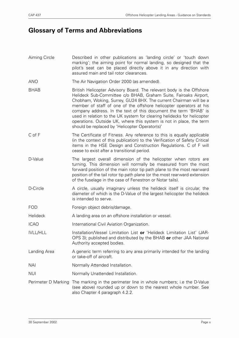
Aiming Circle Described in other publications as ‘landing circle’ or ‘touch downmarking’; the aiming point for normal landing, so designed that thepilot’s seat can be placed directly above it in any direction withassured main and tail rotor clearances.
ANO The Air Navigation Order 2000 (as amended).
BHAB British Helicopter Advisory Board. The relevant body is the OffshoreHelideck Sub-Committee c/o BHAB, Graham Suite, Fairoaks Airport,Chobham, Woking, Surrey, GU24 8HX. The current Chairman will be amember of staff of one of the offshore helicopter operators at hiscompany address. In the text of this document the term ‘BHAB’ isused in relation to the UK system for clearing helidecks for helicopteroperations. Outside UK, where this system is not in place, the termshould be replaced by ‘Helicopter Operator(s)’
C of F The Certificate of Fitness. Any reference to this is equally applicable(in the context of this publication) to the Verification of Safety Criticalitems in the HSE Design and Construction Regulations. C of F willcease to exist after a transitional period.
D-Value The largest overall dimension of the helicopter when rotors areturning. This dimension will normally be measured from the mostforward position of the main rotor tip path plane to the most rearwardposition of the tail rotor tip path plane (or the most rearward extensionof the fuselage in the case of Fenestron or Notar tails).
D-Circle A circle, usually imaginary unless the helideck itself is circular, thediameter of which is the D-Value of the largest helicopter the helideckis intended to serve.
FOD Foreign object debris/damage.
Helideck A landing area on an offshore installation or vessel.
ICAO International Civil Aviation Organization.
IVLL/HLL Installation/Vessel Limitation List or ‘Helideck Limitation List’ (JAR-OPS 3); published and distributed by the BHAB or other JAA NationalAuthority accepted bodies.
Landing Area A generic term referring to any area primarily intended for the landingor take-off of aircraft.
NAI Normally Attended Installation.
NUI Normally Unattended Installation.
Perimeter D Marking The marking in the perimeter line in whole numbers; i.e the D-Value(see above) rounded up or down to the nearest whole number. Seealso Chapter 4 paragraph 4.2.2.
Page x30 September 2002
CAP 437 Offshore Helicopter Landing Areas - Guidance on Standards
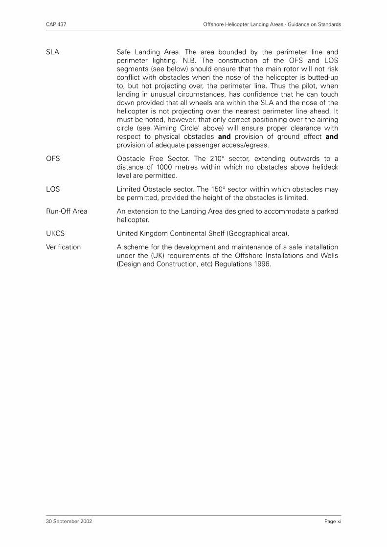
SLA Safe Landing Area. The area bounded by the perimeter line andperimeter lighting. N.B. The construction of the OFS and LOSsegments (see below) should ensure that the main rotor will not riskconflict with obstacles when the nose of the helicopter is butted-upto, but not projecting over, the perimeter line. Thus the pilot, whenlanding in unusual circumstances, has confidence that he can touchdown provided that all wheels are within the SLA and the nose of thehelicopter is not projecting over the nearest perimeter line ahead. Itmust be noted, however, that only correct positioning over the aimingcircle (see ‘Aiming Circle’ above) will ensure proper clearance withrespect to physical obstacles and provision of ground effect and
provision of adequate passenger access/egress.
OFS Obstacle Free Sector. The 210° sector, extending outwards to adistance of 1000 metres within which no obstacles above helidecklevel are permitted.
LOS Limited Obstacle sector. The 150° sector within which obstacles maybe permitted, provided the height of the obstacles is limited.
Run-Off Area An extension to the Landing Area designed to accommodate a parkedhelicopter.
UKCS United Kingdom Continental Shelf (Geographical area).
Verification A scheme for the development and maintenance of a safe installationunder the (UK) requirements of the Offshore Installations and Wells(Design and Construction, etc) Regulations 1996.
Page xi30 September 2002
CAP 437 Offshore Helicopter Landing Areas - Guidance on Standards
Chapter 1 Introduction
1
1.1 History of Development of Criteria for Offshore Helicopter Landing Areas, 1964-
1973
In the early 1960s it became apparent that there would be a continuing requirementfor helicopter operations to take place on fixed and mobile offshore installations.Various ideas were put forward by oil companies and helicopter operators as to theappropriate landing area standards for such operations. In 1964, draft criteria werepublished which used helicopter rotor diameter as a determinant of landing area sizeand associated obstacle-free area. In the light of experience and after furtherdiscussions, the criteria were amended and re-published in 1968. These criteria werethen, and still are, based upon helicopter overall length (from most forward positionof main rotor tip to most rearward position of tail rotor tip, or rearmost extension offuselage if ‘fenestron’ is used). This length is commonly referred to as ‘D’ for anyparticular helicopter as the determinant of landing area size, associatedcharacteristics, and obstacle protected surfaces.
1.2 Department of Energy and the Health and Safety Executive Guidance on the
Design and Construction of Offshore Installations, 1973 Onwards
1.2.1 In the early 1970s, the Department of Energy began the process of collating guidancestandards for the design and construction of ‘installations’ – both fixed and mobile.This led to the promulgation of the Offshore Installations (Construction and SurveyRegulations) 1974, which were accompanied by an amplifying document entitled‘Offshore Installations: Guidance on the design and construction of offshoreinstallations’ (the 4th Edition Guidance). This guidance included criteria for helicopterlanding areas which had been slightly amended from those issued in 1968. During1976 and 1977, the landing area criteria were developed even further during a full-scale revision of this Guidance document, following consultations between the CivilAviation Authority, the British Helicopter Advisory Board and others. This material waseventually published in November 1977 and amended further in 1979. This latteramendment introduced the marking of the landing area to show the datum fromwhich the obstacle-free area originated, the boundary of the area, and the maximumoverall length of helicopter for which operations to the particular landing area weresuitable. The first edition of CAP 437 was published in 1981, amended in 1983 andrevised in December 1993. Since 1990 further changes have been introduced whichinclude the latest helideck criteria internationally agreed and published as Volume II(Heliports) of Annex 14 to the Convention on International Civil Aviation.
1.2.2 In April 1991 the Health and Safety Commission and the Health and Safety Executive(HSE) took over from the Department of Energy the responsibility for offshore safetyregulation. The Offshore Safety Act 1992, implementing the Cullen recommendationsfollowing the Piper Alpha disaster, transferred power to HSE on a statutory footing.HSE also took over sponsorship of the 4th Edition Guidance and Section 55‘Helicopter landing area’ referring to all installations.
1.2.3 Since April 1991, HSE has introduced four sets of modern goal setting regulationswhich contain provisions relating to helicopter movements and helideck safety onoffshore installations. These update and replace the old prescriptive legislation. Theprovisions are as follows:
Chapter 1 Page 130 September 2002
CAP 437 Offshore Helicopter Landing Areas - Guidance on Standards
Regulations Covers
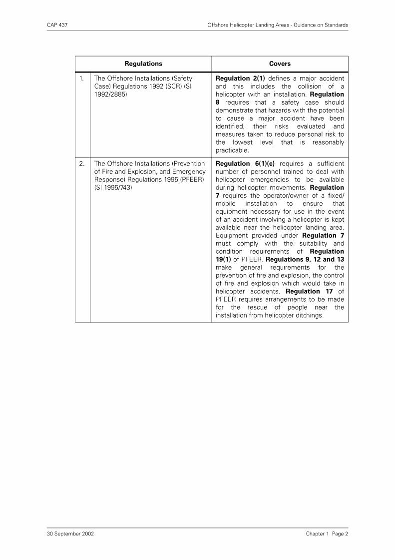
1. The Offshore Installations (Safety Case) Regulations 1992 (SCR) (SI 1992/2885)
Regulation 2(1) defines a major accidentand this includes the collision of ahelicopter with an installation. Regulation
8 requires that a safety case shoulddemonstrate that hazards with the potentialto cause a major accident have beenidentified, their risks evaluated andmeasures taken to reduce personal risk tothe lowest level that is reasonablypracticable.
2. The Offshore Installations (Prevention of Fire and Explosion, and Emergency Response) Regulations 1995 (PFEER) (SI 1995/743)
Regulation 6(1)(c) requires a sufficientnumber of personnel trained to deal withhelicopter emergencies to be availableduring helicopter movements. Regulation
7 requires the operator/owner of a fixed/mobile installation to ensure thatequipment necessary for use in the eventof an accident involving a helicopter is keptavailable near the helicopter landing area.Equipment provided under Regulation 7
must comply with the suitability andcondition requirements of Regulation
19(1) of PFEER. Regulations 9, 12 and 13
make general requirements for theprevention of fire and explosion, the controlof fire and explosion which would take inhelicopter accidents. Regulation 17 ofPFEER requires arrangements to be madefor the rescue of people near theinstallation from helicopter ditchings.
Chapter 1 Page 230 September 2002
CAP 437 Offshore Helicopter Landing Areas - Guidance on Standards
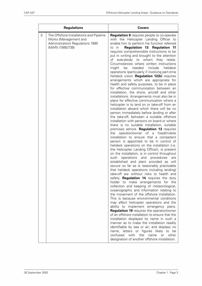
3. The Offshore Installations and Pipeline Works (Management and Administration) Regulations 1995 (MAR) (1995/738)
Regulation 8 requires people to co-operatewith the Helicopter Landing Officer toenable him to perform his function referredto in Regulation 13. Regulation 11
requires comprehensible instructions to beput in writing and brought to the attentionof everybody to whom they relate.Circumstances where written instructionsmight be needed include helideckoperations (particularly if involving part-timehelideck crew). Regulation 12(b) requiresarrangements which are appropriate forhealth and safety purposes, to be in placefor effective communication between aninstallation, the shore, aircraft and otherinstallations. Arrangements must also be inplace for effective communication where ahelicopter is to land on or take-off from aninstallation aboard which there will be noperson immediately before landing or afterthe take-off, between a suitable offshoreinstallation with persons on board or wherethere is no suitable installation, suitablepremises ashore. Regulation 13 requiresthe operator/owner of a fixed/mobileinstallation to ensure that a competentperson is appointed to be in control ofhelideck operations on the installation (i.e.the Helicopter Landing Officer), is presenton the installation, is in control throughoutsuch operations and procedures areestablished and plant provided as willsecure so far as is reasonably practicablethat helideck operations including landing/take-off are without risks to health andsafety. Regulation 14 requires the dutyholder to make arrangements for thecollection and keeping of meteorological,oceanographic and information relating tothe movement of the offshore installation.This is because environmental conditionsmay affect helicopter operations and theability to implement emergency plans.Regulation 19 requires the operator/ownerof an offshore installation to ensure that theinstallation displayed its name in such amanner as to make the installation readilyidentifiable by sea or air; and displays noname, letters or figures likely to beconfused with the name or otherdesignation of another offshore installation.
Regulations Covers
Chapter 1 Page 330 September 2002
CAP 437 Offshore Helicopter Landing Areas - Guidance on Standards
The DCR which came into effect on 30 June 1996, revoke the 1974 Regulations. Theregime requiring installations to possess a Certificate of Fitness issued by an HSEappointed Certifying Authority are now replaced by requirements for operators/owners to introduce verification schemes in respect of the safety critical elements oftheir installations. The 4th Edition will be maintained throughout the two-yeartransitional period for the introduction of the new verification arrangements as itcontains information which the industry continues to find useful. HSE will continue todiscuss with the industry and others the future of such technical guidance.
1.3 Applicability of Standards in Other Cases
1.3.1 For vessels engaged in supporting mineral exploitation (such as crane or derrickbarges, pipe-laying vessels, fire and rescue vessels, seismic research vessels, etc),which are not offshore installations and so do not require a Certificate of Fitness orverification scheme, the Authority recommends the application of the samestandards for the helicopter landing areas contained in this CAP and as are given inthe 4th Edition Guidance. Compliance with this recommendation will enablehelicopter operators to fulfil their own legal obligations and responsibilities.
1.3.2 On other merchant vessels where it is impracticable for these standards to beachieved, for example, where the landing area has to be located amidships, thecriteria to be used are included in Chapter 9 of this publication. Also in that chapter isguidance applicable to vessels involved on infrequent helicopter services in parts ofthe world other than the UKCS, or which may require facilities for helicopter winchingactivities only. Whilst this material covers the main aspects of criteria for a helicopterlanding or manoeuvring area, there may be operational factors involved with thesevessels such as air turbulence; flue gases; excessive helideck motion; or the size ofrestricted amidships landing areas, on which guidance should be obtained from thehelicopter operator or BHAB and from competent specialists.
1.4 Review of CAP 437
Between 1992 and 1995 a programme of offshore installation helideck inspectionswas carried out. The inspections were carried out jointly by the Authority’sAerodrome Standards Inspectorate and the Health and Safety Executive (OffshoreSafety Division). Experience gained during the inspections has been incorporated,where relevant, in this text.
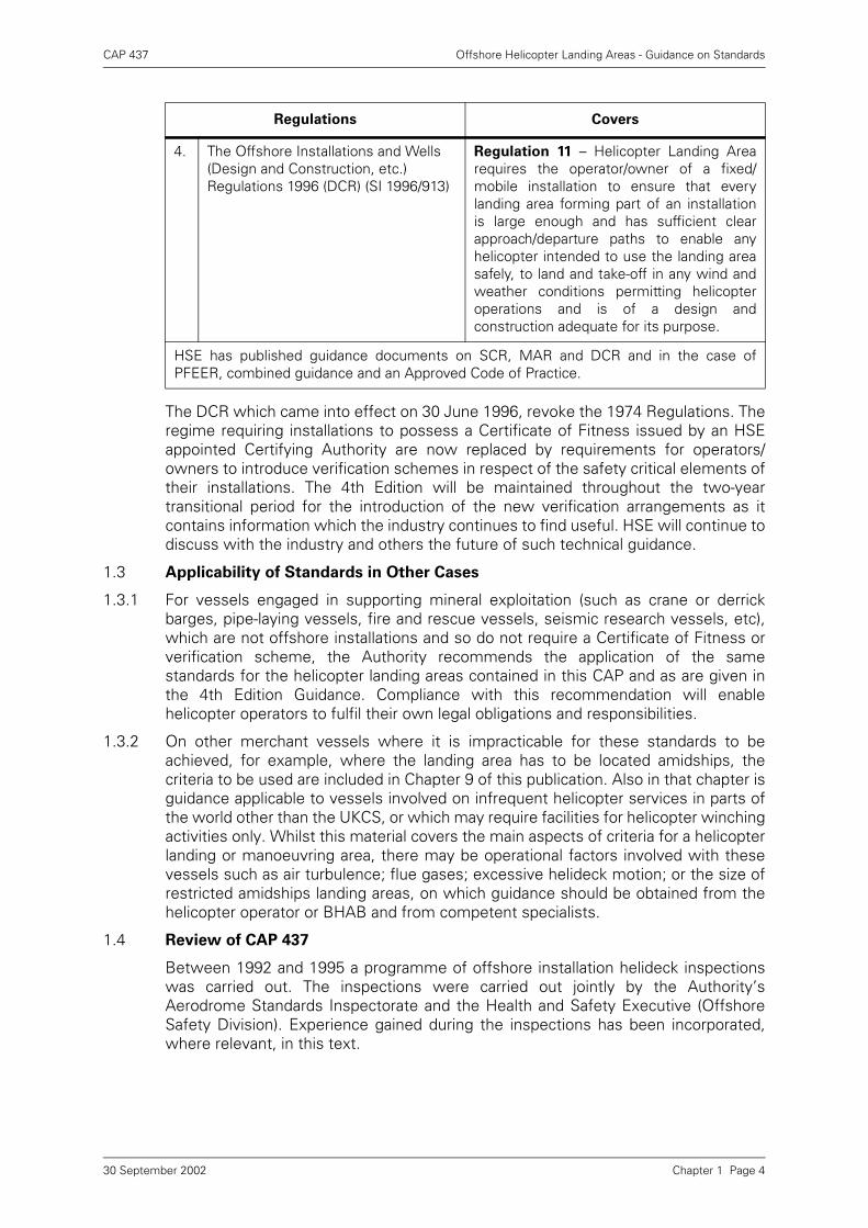
4. The Offshore Installations and Wells (Design and Construction, etc.) Regulations 1996 (DCR) (SI 1996/913)
Regulation 11 – Helicopter Landing Arearequires the operator/owner of a fixed/mobile installation to ensure that everylanding area forming part of an installationis large enough and has sufficient clearapproach/departure paths to enable anyhelicopter intended to use the landing areasafely, to land and take-off in any wind andweather conditions permitting helicopteroperations and is of a design andconstruction adequate for its purpose.
HSE has published guidance documents on SCR, MAR and DCR and in the case ofPFEER, combined guidance and an Approved Code of Practice.
Regulations Covers
Chapter 1 Page 430 September 2002
CAP 437 Offshore Helicopter Landing Areas - Guidance on Standards
1.5 Worldwide Application
1.5.1 It should be noted that references are made to United Kingdom legislatory andadvisory bodies. However, this document is written so that it may provide usefulguidance on minimum standards applicable for the safe operation of helicopters tooffshore helidecks throughout the world.
1.5.2 The guidance is therefore particularly relevant to UK registered helicopters operatingwithin and outwith the UKCS areas; whether or not they have access to the BHABprocess. In cases where the accepted BHAB process is not applicable or available andwhere reference is made to BHAB in this document it can be substituted by thephrase ‘the helicopter operator’ – who should have in place a system for assessingand authorising the operational use of each helideck. Within Europe, under the controlof the Joint Aviation Authority (JAA) through Joint Aviation Requirements (JAR-OPS3), authorisation of each helideck is a specific Requirement (JAR-OPS 3.220) andguidance on the criteria for assessment is given in an ‘acceptable means ofcompliance’ (AMC) to this Requirement.
1.5.3 Outside UKCS other European helicopter operators will have in place systems whichcomply with the JAR-OPS 3 Requirement but which may not utilise the BHABprocess in favour of a more local system which satisfies the National Authority.Throughout the range of operations covered by JAR-OPS agreement has been madeto share all helideck information between helicopter operators by the fastest possiblemeans.
1.5.4 Other helicopter operators, who operate outside the areas covered by the JAA andwho are using this guidance document, are recommended to establish a system forassessing and authorising each helideck for operational use. It is a fact that manyInstallations and vessels do not fully comply with the criteria contained in thefollowing chapters. A system for the assessment of the level of compliance plus asystem for imposing compensating operational limitations is the only way of ensuringthat the level of safety to flights is not compromised.
Chapter 1 Page 530 September 2002
CAP 437 Offshore Helicopter Landing Areas - Guidance on Standards
Chapter 2 Page 1
Chapter 2 Aircraft Performance Considerations
2.1 General Considerations
The guidance for helicopter landing areas on offshore installations or vessels resultsfrom the need to ensure that United Kingdom registered helicopters are able tooperate safely at all times. Public transport helicopters operate in accordance withperformance criteria and handling techniques contained in the aircraft flight manualand the operator’s Operations Manual, both of which are examined by the Authorityas part of the requirements for the grant and maintenance of an Air Operator’sCertificate (AOC).
2.2 Safety Philosophy
2.2.1 Aircraft performance data is scheduled in the Flight Manual to enable the operator tocomply with the principal performance requirement that, in the event of a power unitfailure, the safety of the aircraft and its occupants remains assured in the ambientconditions. This means, in general terms, that following an engine failure the aircraftcan either re-land at the take-off point, continue with landing at the intended landingpoint, or fly to a place where a safe landing can be made.
2.2.2 Operations Manuals outline flying procedures and the criteria to be used to ensurethat helicopters are operated in a way which minimises exposure of the aircraft andits occupants during the short critical period following a power unit failure during theinitial stage of take-off, or final stage of landing.
2.2.3 The Authority is currently researching the effects upon helicopter performance andcontrol created by the offshore helideck environment in order to establish whetherthere is a need for additional procedures and/or revised criteria.
2.3 Factors Affecting Performance Capability
Helicopter performance is a function of many factors including the actual all-upweight;ambient temperature; pressure altitude; effective wind speed component; andoperating technique. Other factors, concerning the physical and airflowcharacteristics of the helideck and associated or adjacent structures, will alsocombine to affect the length of the exposure period referred to in paragraph 2.2above. These factors are taken into account in the determination of specific andgeneral limitations which may be imposed in order to ensure adequate performanceand to ensure that the exposure period is kept to a minimum. In many circumstancesthe period will be zero. It should be noted that, following a power unit failure, it willfrequently be necessary for the helicopter to descend below deck level to gainsufficient speed to subsequently fly away, or in rare circumstances, to land on thewater. In certain circumstances, where exposure periods would otherwise beunacceptably long, it may be necessary to reduce helicopter weight (and thereforepayload) to reduce the risk to an acceptable level; or it may be necessary to suspendflying operations. In many cases, other than those due to the effects of severeweather conditions, these circumstances relate primarily to failings and deficienciesin application of the criteria documented in the following text.
30 September 2002
CAP 437 Offshore Helicopter Landing Areas - Guidance on Standards
Chapter 3 Helicopter Landing Areas – Physical
Characteristics
3.1 General
3.1.1 This chapter provides guidance on the physical characteristics of helicopter landingareas (helidecks) on offshore installations and vessels. It should be noted that wherea Verification Scheme is required it should state for each helicopter landing area themaximum size of helicopter in terms of D-value for which that area is certificated orverified with regard to strength and size in accordance with these requirements.Where these criteria cannot be met in full for a particular size of helicopter, theVerification Agency should consult the BHAB Helideck Sub-Committee on anyoperational restrictions that may be considered necessary in order to compensate fordeviations from and non-compliance with these criteria. The BHAB will informhelicopter operators of any such restrictions through the IVLL.
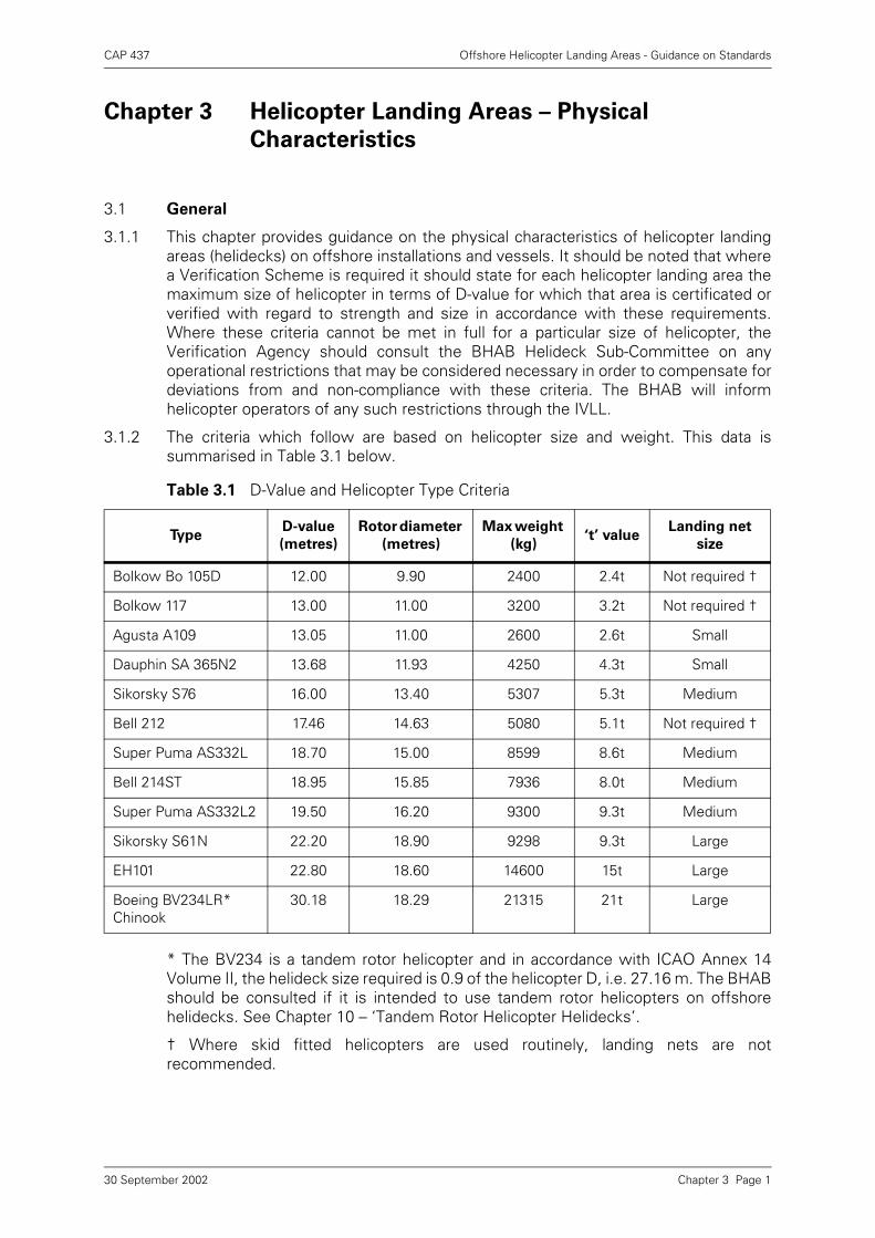
3.1.2 The criteria which follow are based on helicopter size and weight. This data issummarised in Table 3.1 below.
* The BV234 is a tandem rotor helicopter and in accordance with ICAO Annex 14Volume II, the helideck size required is 0.9 of the helicopter D, i.e. 27.16 m. The BHABshould be consulted if it is intended to use tandem rotor helicopters on offshorehelidecks. See Chapter 10 – ‘Tandem Rotor Helicopter Helidecks’.
† Where skid fitted helicopters are used routinely, landing nets are notrecommended.
Table 3.1 D-Value and Helicopter Type Criteria
TypeD-value
(metres)
Rotor diameter
(metres)
Max weight
(kg)‘t’ value
Landing net
size
Bolkow Bo 105D 12.00 9.90 2400 2.4t Not required †
Bolkow 117 13.00 11.00 3200 3.2t Not required †
Agusta A109 13.05 11.00 2600 2.6t Small
Dauphin SA 365N2 13.68 11.93 4250 4.3t Small
Sikorsky S76 16.00 13.40 5307 5.3t Medium
Bell 212 17.46 14.63 5080 5.1t Not required †
Super Puma AS332L 18.70 15.00 8599 8.6t Medium
Bell 214ST 18.95 15.85 7936 8.0t Medium
Super Puma AS332L2 19.50 16.20 9300 9.3t Medium
Sikorsky S61N 22.20 18.90 9298 9.3t Large
EH101 22.80 18.60 14600 15t Large
Boeing BV234LR* Chinook
30.18 18.29 21315 21t Large
Chapter 3 Page 130 September 2002
CAP 437 Offshore Helicopter Landing Areas - Guidance on Standards
3.2 Location
The location of a specific helideck is often a compromise given the competingrequirements for space but the following general points should be considered:-
a) it is located on the installation, with respect to prevailing wind conditions, in sucha position that any structure induced airflow and temperature effects areminimised (see paragraph 3.3);
b) the clear approach and take-off sector recommended in paragraph 3.7 is available,with due regard to prevailing winds;
c) air turbulence and the quality of the airflow due to adjacent structures, hydrocarbonemissions, and temperature gradients created by such items as hot plumes andgas turbine exhausts are minimised and remain acceptable for all wind directions(see paragraph 3.3). If these conditions cannot be met it may be necessary toimpose limitations on payloads or on certain approach directions. In extreme casesthese limitations may create unacceptably severe restrictions for the owner/operator. In such cases consideration can be given to providing a second landingarea at the opposite side of the installation to cater for wind directionsunfavourable to the primary site;
d) installation emergency (blowdown) systems which are designed to dischargehydrocarbon gases should be designed so that any emissions are controllable, andare not initiated automatically and instantaneously without consideration ofsufficient warning to helicopter operators. All such blowdown or similar systemsshould be discussed in detail with the BHAB at an early stage in the designprocess. Systems which can discharge hydrocarbons without sufficient warningmay attract permanent approach bans in certain wind directions and a totalapproach ban when the wind conditions are ‘nil’ or ‘light and variable’;
e) helidecks should be at or above the highest point of the main structure. This is adesirable feature but it should be appreciated that if this entails a landing areamuch in excess of 60 metres above sea level, the regularity of helicopteroperations may be adversely affected in low cloud base conditions;
f) from the helicopter pilot’s point of view, the preferred approach and take-off pathfor the helicopter would be in such a direction(s) that the Captain, in the right-handseat, has the best view of the obstacle environment in the prevailing wind;
g) taking into account and allowing for all the points above, on balance the bisector ofthe obstacle free sector should be positioned facing into the prevailing wind so thatthe helicopter can approach into wind with the deck in the right-hand quadrant asviewed from the helicopter and facilitating an into wind overshoot in the clear(OFS) sector;
h) ready and protected access to and from the accommodation area is providedwithout the need to pass through working areas;
i) attention must also be paid to the probability of positioning other helidecks andstructures (e.g. flotels, crane barges, drilling rigs, additional modules etc.) in closeproximity to the design deck. Consideration must be given to the effect of adjacentstructures of one installation (or vessel) affecting air quality and obstacle protectedsurfaces of another installation (or vessel).
Chapter 3 Page 230 September 2002
CAP 437 Offshore Helicopter Landing Areas - Guidance on Standards
3.3 Air Turbulence, Temperature Gradient and the Helideck Environment
3.3.1 The Authority, in conjunction with the HSE, is currently carrying out a research projectinto Helideck Environmental Issues. A CAA paper will be published in due course. Thisongoing work will highlight new information for consideration by offshore installationand vessel designers, owners/operators and helicopter operators.
NOTE: Disturbances to a smooth airflow, regardless of cause or the properties of thephenomena, are generally described as ‘turbulence’. Whereas the effects felt insidean aircraft may be similar, it is important to appreciate the differences betweenturbulence, windshear and flight in the vicinity of hot exhausts.
3.3.2 Turbulent airflows across the landing area can be caused by wind flow around otherparts of the installation or vessel structure (and by adjacent structures) and by othersystem exhausts (in particular gas turbines), which can also cause temperaturegradients. These effects can seriously influence helicopter handling and/orperformance. The quality of the air on approach and over the helideck can be seriouslydegraded by hot and cold hydrocarbon vents.
3.3.3 All aircraft will perform to their maximum efficiency in smooth airflow. This isparticularly important during take-off and landing manoeuvres where disruptions tosmooth airflow are particularly unwelcome when the aircraft is close to the ground (orsea, or landing platform). It is a paradoxical fact that an offshore helideck andassociated or adjacent structures may well be the only generator of turbulent airflowin the helicopter’s flight path. For this reason the helideck must be considered alwaysto sit within turbulence generators and every effort must be made to ‘design out’such generators and minimise the effects. Turbulence generators and degraded airquality can be created by two distinct sources:
a) solid objects and structures which create turbulent airflow and/or vertical windcomponents around, above and downwind of the structure and
b) exhaust emissions, and efflux from cold gas outlets and hot gas outlets.
3.3.4 In the case of paragraph 3.3.3 a) above, the path of the turbulence can be reasonablypredicted given that information is available as to the direction and speed of the(unaffected) natural wind. Clad derricks can provide considerable control difficultiesfor a helicopter pilot; whereas open, lattice-type structures generate less turbulenteffects. Light and variable, or nil wind conditions will probably result in generation ofno significant turbulence (even from clad derricks and other solid structures) as thereis little or no ‘downwind effect’. Turbulence generated by solid structures can be saidto increase as a direct function of the natural (unaffected) wind speed.
3.3.5 Landing areas situated directly on top of deep slab-sided structures such asaccommodation modules, have been known to suffer from excess vertical airflowcomponents unless there is sufficient separation to allow airflow beneath thehelideck. Sufficient airspace directly beneath the helideck itself will have the effect ofsmoothing out the flow over the surface of the helideck and minimise the verticalwind component. Such airspace should be preserved and protected and not allowedto become cluttered by later installation of other large objects which may negate theeffect which the airspace is designed to provide.
3.3.6 As a general rule, the vertical component of airflows resulting from horizontal windvelocities up to 25 metres per second (48.6 kt) should not exceed ±0.9 metres persecond (1.75 kt) over the landing area at main rotor height.
3.3.7 The case of paragraph 3.3.3 b) above, is more complex and can be more insidious. Anapproaching helicopter will probably be downwind of the efflux from the platformemission sources. Such efflux can extend a considerable distance downwind of the
Chapter 3 Page 330 September 2002
CAP 437 Offshore Helicopter Landing Areas - Guidance on Standards
installation; and in conditions of poor visibility and at night the pattern of efflux maynot be obvious to the pilot. It is essential therefore that such emission patterns areproperly identified and documented through model testing and this information ismade available to the BHAB for inclusion in the IVLL. Plume studies can be carriedout to show dispersion and temperature gradients in various wind speeds anddirections. In general, all sources of emission should be designed to be as far awayfrom the helideck as possible and located so that the prevailing wind will ensuremaximum separation between plume and helicopter approach path. In light andvariable wind conditions or in conditions of ‘nil wind’ it will be difficult to predict thepattern of any emission plume. Pockets of gases could conceivably accumulate,unseen, in an unpredictable, haphazard dispersion pattern dictated by random effectsof air densities and air movement. The gases could establish a presence in the vicinityof the helideck and could provide the pilot with a dangerous combination of controland power disadvantage. The insidious nature of this effect is exacerbated in theabsence of any warning. It therefore follows that all exhaust and venting emissionsmust be properly identified and documented; and that these may attract limitations incertain specific wind direction segments; and on a 360° (total approach ban) basis inlight or nil wind conditions. One helicopter accident in the UKCS (S61, August 1995)has been attributed to the effect of gas turbine exhaust emissions in nil or light andvariable wind conditions. Such conditions are currently difficult to model and plumestudies under these test conditions have not historically been considered. The NorthSea is usually a windy place and wind, apart from any turbulence effect, is generallyseen to have a beneficial effect on available power and controllability during take-offand landing. Flight crews should note in particular the adverse and potentiallyhazardous effects which nil or light and variable winds can have on exhaust emissionand cold gas dispersion.
3.3.8 Hot (lit) gas plumes provide a good visual indication of their presence and of the plumecharacteristics and are generally therefore avoidable; though they can createunacceptable operational conditions. For example, they can increase ambienttemperatures in the vicinity of the helideck to the extent that helicopter performanceis degraded and must be accounted for. Where such effects are shown to be possiblethe helideck environment should be monitored. It may be necessary to imposelimitations when such effects are taken into account.
3.3.9 In consideration of the effects of ambient temperature increases over the helideckarea due to flare plumes or exhaust emissions, unless it is obvious that the airtemperature in the vicinity of the flight paths to and from the helideck or adjacenthelidecks will not be affected by the exhaust plume, a survey of ambienttemperatures should be conducted. Where ambient temperature, in the vicinity of theflight paths and over the landing area, is increased by more than 2°C the BHAB shouldbe informed. Rises of 2°C or more above ambient temperatures become anoperational issue and require helicopter operators’ review.
Ambient temperature information is required for computation of the helicopter’smaximum all up weight. Current research findings indicate that additionalconsiderations should be made by installation and helideck designers and by testingfacilities to ensure that the 2°C ambient temperature rise is that occurring over a 3second time interval, at a height above helideck level which takes into considerationthe airspace required above the helideck to accommodate helicopter landing andtake-off decision points. A CAA Paper on the subject of helideck environmentalissues, including ambient temperature, will be published in due course.
Chapter 3 Page 430 September 2002
CAP 437 Offshore Helicopter Landing Areas - Guidance on Standards
3.3.10 Cold gas emissions have, over the last few years, become a feature of installationdesign due to the incorporation of certain safety sytems. These systems, known as‘Blowdown Systems’ or ‘Rapid Blowdown Systems’, can release varying amounts ofcold gas in certain platform malfunction situations. Such systems should always bedesigned to preclude unannounced release of cold gas. No matter how remote thepossibility, any release of cold gas in the vicinity of a helicopter could have veryserious results. Some systems in current use have the facility of containment of therelease of hydrocarbons in dealing with the malfunctions for which they are designedto cope. Such release can be programmed to ensure that helicopter operations do nottake place coincidentally. It is also understood, however, that some systems canproduce cold gas with very little warning. It is essential that the BHAB is given a fullunderstanding of the nature of any cold gas release system design; under whatcircumstances hydrocarbons may be released; and the highest volumes anticipated,so that an assessment of the risk can be made. The risk due to the possibility ofunannounced cold gas release is a serious one due to the probable catastrophic effecton a helicopter (and its passengers and crew). Consideration must be given in thiscase to applying permanent approach bans in certain conditions of wind speed anddirection. The installation of ‘Status Lights’ (see Chapter 4, paragraph 4.3.6) is notconsidered to be a solution to all potential flight safety issues arising from cold gasemissions; these lights are only a warning that the helideck is in an unsafe conditionfor helicopter operations.
Recent research into helideck environmental issues indicates that a limit of 10% LFLshould be the maximum permissible concentration of hydrocarbon gas within thehelicopter operating area. This level of concentration has been shown to have littlesignificant effect on engines and rotor systems. However, helicopters will notknowingly operate in any level of hydrocarbon gas. Installation operators must havein place a management system which ensures that all helicopters in the vicinity of anyrelease are immediately advised to stay clear.
3.3.11 All hydrocarbon cold vent systems should be designed to terminate and discharge ata location on the Installation as far from the helideck environs as possible. Thepotential release volumes, flammable concentrations, and dispersal characteristicsshould be quantified. This approach allows the helideck designer to apply a ‘no flyzone’ around the hazardous area. A similar approach should be taken when designingInstallation exhaust and flare systems. If there is evidence on the process controlpanel of a major process upset condition arising, the General Alarm should besounded, alternatively the Gas Alarm. The Radio Operator/HLO should already havebeen advised if helicopter movements are taking place, so that the he can advisehelicopters to stay clear. Helideck Status Light Systems should be activated at thisstage.
3.3.12 The combined effects of airflow direction and turbulence; prevailing wind; installationexhaust emissions; and the plumes from hot and cold gas vents and releases shouldbe determined for each installation. Further information on these matters can befound in Davies et al 1977 and 1979, and Davies 1979 (see Appendix B, ref 1). Suitablemodel tests should be carried out to confirm the suitability of the arrangements. Theresulting information, in summary format, should be made available to the BHAB.
3.3.13 In assessment of helideck physical characteristics, and the quality of the surroundingair attention must always be paid to adjacent fixed installations (whether separate orbridge-linked), mobile installations and vessels, of a permanent or temporary nature.These can affect helicopter operations due to infringement of obstacle protectedsurfaces and also due to the presence of (additional) emissions and turbulencegenerators. For practical purposes, in this context and until research results (seeparagraph 3.3.1 above) indicate otherwise, each helideck protection zone should be
Chapter 3 Page 530 September 2002
CAP 437 Offshore Helicopter Landing Areas - Guidance on Standards
considered to be the airspace extending from sea level to 2000 feet above sea leveland within 1000 metres of the helideck.
3.3.14 Previous editions of CAP 437 have suggested that ‘some forms of exhaust plumeindication should be provided for use during helicopter operations, for example, by theproduction of coloured smoke’. There appears to have been a reluctance on the partof installation operators to consider this. In some circumstances introduction ofsmoke into exhaust emissions would not only make visible an otherwise invisiblehazard but could also enable operational strategies to be developed which couldminimise operational restrictions.
3.4 Structural Design
Offshore installations may be designed for a specific type of helicopter. Optimumoperational flexibility will be gained from consideration of the potential life and usageof the facility together with developments in helicopter design and technology. Somecomfort may be gained from the fact that a considerable period of time is required totranslate a conceptual design into commercial production of a helicopter. The landingand take-off area should be designated for the heaviest and largest helicopter it isanticipated will use the facility (Table 3.1). Consideration in the design must also begiven to other types of loading such as personnel, traffic, snow, freight, fuellingequipment etc. For the purpose of design it is to be assumed that single main rotorhelicopters will land on the wheel or wheels of two main undercarriages or skids (iffitted) and that the tandem main rotor helicopter will land on the wheel or wheels ofall main undercarriage centres of the specified helicopter and divided equally betweenthe two main undercarriages. For tandem main rotor helicopters the total loadsimposed on the structure should be taken as concentrated loads on the undercarriagecentres of the specified helicopter and distributed between the main undercarriagesin the proportion in which they carry the maximum static loads. The concentratedundercarriage loads should normally be treated as point loads but whereadvantageous a tyre contact area may be assumed in accordance with themanufacturer’s specification. The maximum take-off weight and undercarriagecentres for which the platform has been designed and the maximum size and weightof helicopter for which the deck is suitable should be stated in the Installation/VesselOperations Manual, the Certificate of Fitness or; the Verification documentation.Plastic design considerations may be applied for the deck (i.e. plating and stiffenersonly) but elastic considerations must be applied to the main supporting members (i.e.girders, trusses, pillars, columns etc.).
Notes: 1 Helideck strength requirements contained in this paragraph and thefollowing paragraphs 3.5 and 3.6 are those defined in the Health andSafety Executive Guidance Notes (Offshore Installations: Guidance ondesign, construction and certification, Section 55.5).
2 Consideration should be given to the possibility of accommodating anunserviceable helicopter on the side of the deck while a relief helicopteris required to land. If this contingency requirement is designed into theconstruction/operating philosophy the helicopter operator must beinformed of any weight restrictions imposed on the relief helicopter bythe structural integrity.
Chapter 3 Page 630 September 2002
CAP 437 Offshore Helicopter Landing Areas - Guidance on Standards
3.5 Loads – Helicopters Landing
The helicopter landing area should be designed to withstand all stresses that resultfrom a helicopter landing. The following must be taken into account:
a) Dynamic load due to impact landing. This must cover both a heavy normallanding and an emergency landing. For the former, an impact load of 1.5 xmaximum take-off weight (MTOW) of the helicopter should be used, distributed asdescribed in paragraph 3.4 above. This should be treated as an imposed load,applied together with the combined effect of b) to f) below in any position on thesafe landing area so as to produce the most severe landing condition for eachelement concerned. For the latter an impact load of 2.5 x MTOW should be appliedin any position on the landing area together with the combined effects of b) to f)inclusive.
b) Sympathetic response of landing platform. The dynamic load (see a) above)should be increased by a structural response factor depending upon the naturalfrequency of the deck structure when considering the design of supporting beamsand columns. Unless values based upon particular undercarriage behaviour anddeck frequency are available, it is recommended that a minimum structureresponse factor of 1.3 should be used. For the Boeing BV 234LR Chinook refer toChapter 10.
c) Overall superimposed load on the landing platform. To allow for snow load/personnel etc; in addition to the wheel loads an allowance of 0.5 kN/m2 should beincluded in the design.
d) Lateral load on landing platform supports. The supports of the platform shouldbe designed to resist concentrated horizontal imposed loads equivalent to 0.5 xmaximum take-off weight of the helicopter, distributed between theundercarriages in proportion to their vertical loading. This should be applied in thedirection which will produce the most severe loading conditions for each elementconcerned.
e) Dead load of structural members.
f) Wind loading. Wind loading should be allowed for in the design of the platform inaccordance with Section 11 of the HSE Guidance (Environmental considerations).This should be applied in the direction which, together with the imposed loading ind) above, will produce the most severe loading condition for each elementconcerned.
3 Alternative loading criteria equivalent to those recommended here and in
paragraphs 3.5 and 3.6 may be used where aircraft specific loads have been
derived by the aircraft manufacturer from an appropriate assessment
which takes account of the full range of potential landing conditions,
including failure of a single engine at a critical point, and the behaviour of
the aircraft undercarriage. The aircraft manufacturer must be able to
provide information to interested parties, including the owner or operator
of the installation and the helicopter operator to justify any such
alternative criteria. The aircraft manufacturer may wish to seek the opinion
of the Authority on the basis of the criteria to be used. In consideration of
alternative criteria the Authority is content to assume that the single
engine failure is the case among likely survivable emergencies which
would generate the highest vertical rate of descent on to the helideck.
Chapter 3 Page 730 September 2002
CAP 437 Offshore Helicopter Landing Areas - Guidance on Standards
g) Punching shear. A check should be made for the punching shear of anundercarriage wheel with a contact area of 65 x 103 mm2. Particular attention todetailing should be taken at the junction of the supports and the platform deck.
3.6 Loads – Helicopters at Rest
The helicopter platform should be designed to withstand all stresses that result froma helicopter at rest; the following must be taken into account:
a) Imposed load from helicopter at rest. The entire helicopter platform must bedesigned to carry an imposed load equal to the maximum take-off weight of thehelicopter. This should be distributed between all the undercarriages of thehelicopter. It should be applied in any position on the helicopter platform so as toproduce the most severe loading condition for each element concerned.
b) Overall superimposed load, dead load and wind load. The values for theseloads are the same as given in paragraph 3.5 above and should be used incombination with a) above. Consideration should also be given to the additionalwind loading from a secured helicopter.
c) The effect of acceleration forces and other dynamic amplification forces arisingfrom the predicted motions of the installation, principally mobiles and vessels, inthe appropriate environmental condition should be considered where applicable.
3.7 Size and Obstacle Protected Surfaces
3.7.1 For any particular type of single main rotor helicopter, the helideck should besufficiently large to contain a circle of diameter D equal to the largest dimension ofthe helicopter when the rotors are turning. This D circle should be totally unobstructed(see Table 3.1 for D values). Due to the actual shape of most offshore helidecks theD circle will be ‘imaginary’ but the helideck shape must be capable of accommodatingsuch a circle within its physical boundaries.
3.7.2 From any point on the periphery of the above mentioned D circle an obstacle-freeapproach and take-off sector should be provided which totally encompasses the safelanding area (and D circle) and which extends over a sector of at least 210°. Withinthis sector, and out to a distance of 1000 metres from the periphery of the landingarea, only the following items may exceed the height of the landing area, but shouldnot do so by more than 0.25 metres:
• the guttering or slightly raised kerb (associated with the requirements in paragraph3.8.2);
Chapter 3 Page 830 September 2002
CAP 437 Offshore Helicopter Landing Areas - Guidance on Standards
• the lighting required by Chapter 4;
• the outboard edge of the safety net required in paragraph 3.10;
• the foam monitors;
• those handrails and other items associated with the landing area which areincapable of complete retraction or lowering for helicopter operations.
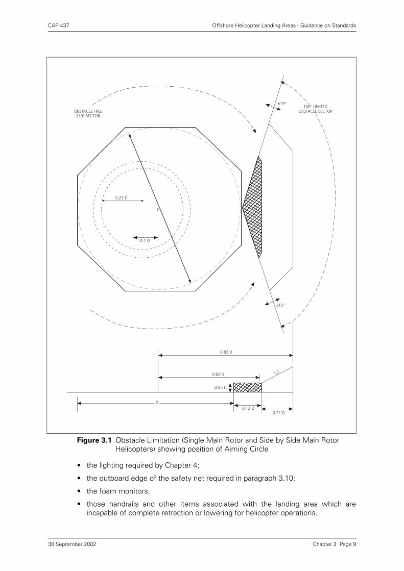
Figure 3.1 Obstacle Limitation (Single Main Rotor and Side by Side Main Rotor Helicopters) showing position of Aiming Circle
±15°150° LIMITED
OBSTACLE SECTOROBSTACLE FREE210° SECTOR
0.25 D
D
0.1 D
±15°
0.83 D
0.62 D
0.05 D
0.12 D0.21 D
1:2
D
Chapter 3 Page 930 September 2002
CAP 437 Offshore Helicopter Landing Areas - Guidance on Standards
3.7.3 The bisector of the 210° obstacle free sector should normally pass through the centreof the D circle. The sector may be ‘swung’ by up to 15° as illustrated in Figure 3.1 andparagraph 10.2 but not for bi-directional landing rectangles (See Chapter 10).Acceptance of the ‘swung’ criteria will normally only be applicable to existingInstallations.
3.7.4 The Diagram at Figure 3.1 shows the extent of the two segments of the 150° LimitedObstacle Sector (LOS) and how these are measured from the centre of the(imaginary) ‘D’ Circle and from the perimeter of the SLA. This diagram assumes, sincemost helidecks are designed to the minimum requirement of accommodating a 1 ‘D’Circle, that the ‘D’ Circle perimeter and SLA perimeter are coincidental. No objectsabove 0.05D are permitted in the first (hatched area in Figure 3.1) segment of theLOS. The first segment extends out to 0.62D from the centre of the ‘D’ Circle, or0.12D from the SLA perimeter marking. The second segment of the LOS, in which noobstacles are permitted within a rising 1:2 slope from the upper surface of the firstsegment, extends out to 0.83D from the centre of the ‘D’ Circle, or a further 0.21Dfrom the edge of the first segment of the LOS.
The exact point of origin of the LOS is assumed to be at the periphery of the ‘D’ Circle.
Some helidecks are able to accommodate a SLA which covers a larger area than thedeclared ‘D’ value; a simple example being a rectangular deck with the minordimension able to contain the ‘D’ Circle. In such cases it is important to ensure thatthe origin of the LOS (and OFS) is at the SLA perimeter as marked by the perimeterline. Any SLA perimeter must guarantee the obstacle protection afforded by bothsegments of the LOS. The respective measurements of 0.12D from the SLAperimeter line, plus a further 0.21D are to be applied. On these larger decks there isthus some flexibility in deciding the position of the perimeter line and SLA in order tomeet the LOS requirements and when considering the position and height of fixedobstacles. Separating the origin of the LOS from the perimeter of the ‘D’ Circle inFigure 3.1 and moving it to the right of the page will demonstrate how this might applyon a rectangular SLA.
The extent of the LOS segments will, in all cases, be lines parallel to the SLAperimeter line and follow the boundaries of the SLA perimeter (see Figure 3.1). Onlyin cases where the SLA perimeter is circular will the extent be in the form of arcs tothe ‘D’ circle. However, taking the example of an octagonal SLA as drawn at Figure3.1, it would be possible to replace the angled corners of the two LOS segments witharcs of 0.12D and 0.33D centred on the two adjacent corners of the SLA; thus cuttingoff the angled corners of the LOS segments. If these arcs are applied they must notextend beyond the two corners of each LOS segment so that minimum clearances of0.12D and 0.33D from the corners of the SLA are maintained. Similar geometricconstruction may be made to a square or rectangular SLA but care must be taken toensure that the LOS protected surfaces minima can be satisfied from all points on theSLA perimeter.
Chapter 3 Page 1030 September 2002
CAP 437 Offshore Helicopter Landing Areas - Guidance on Standards
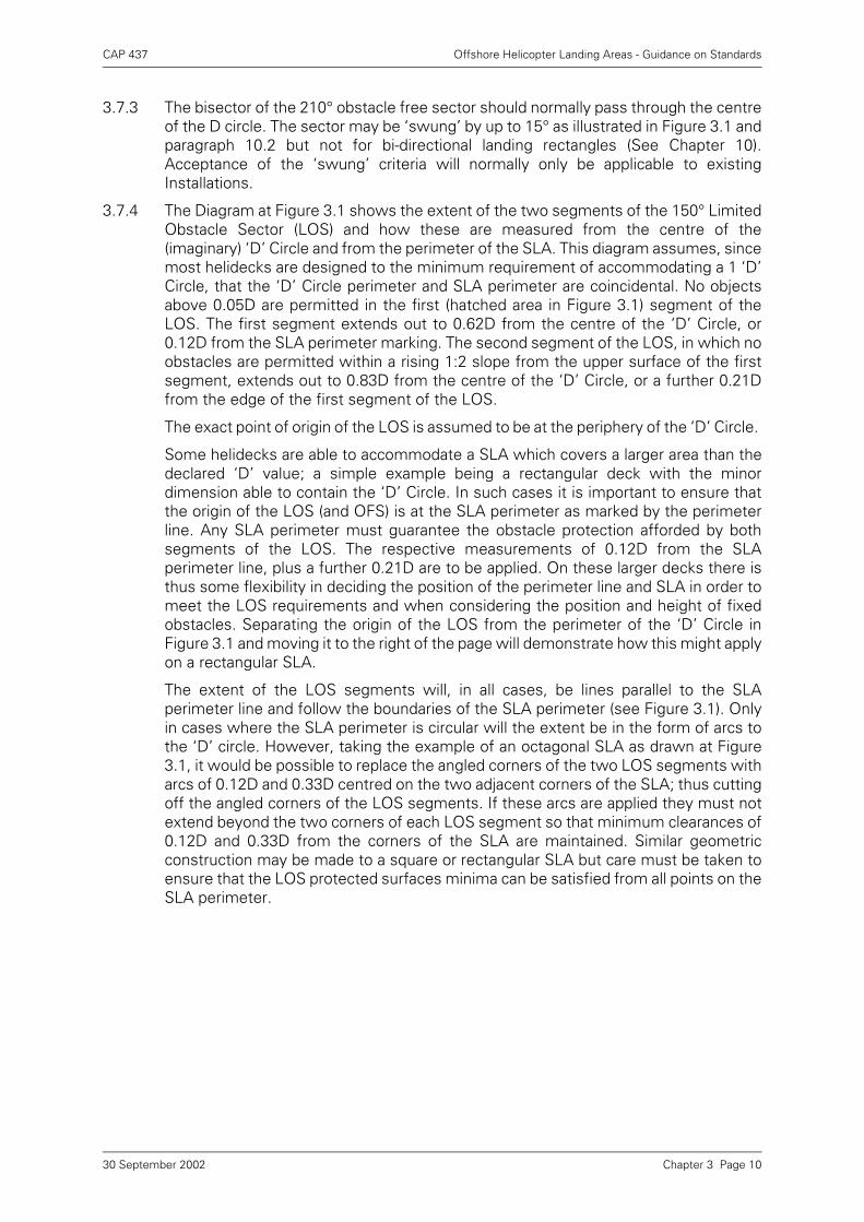
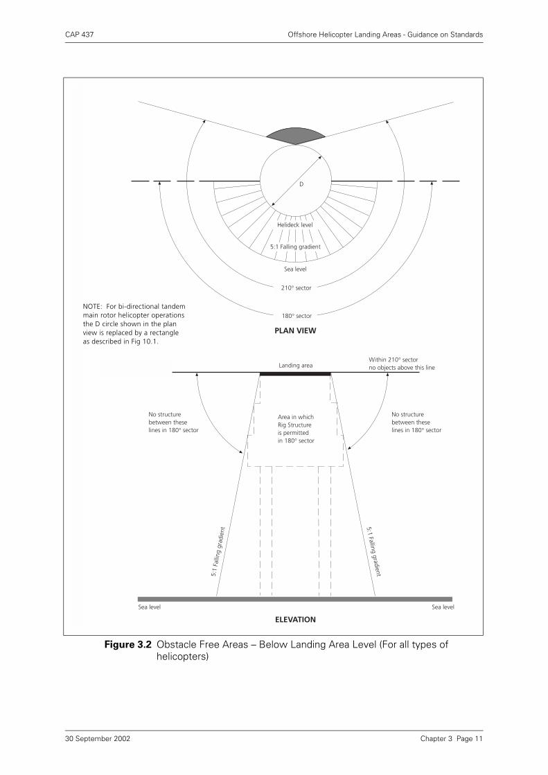
Figure 3.2 Obstacle Free Areas – Below Landing Area Level (For all types of helicopters)
D
Sea level
Helideck level
5:1 Falling gradient
210° sector
180° sector
Landing areaWithin 210° sectorno objects above this line
Area in whichRig Structureis permittedin 180° sector
No structurebetween theselines in 180° sector
Sea levelSea level
No structurebetween theselines in 180° sector
5:1
Falli
ng g
radi
ent
PLAN VIEW
ELEVATION
5:1 Falling gradient
NOTE: For bi-directional tandemmain rotor helicopter operationsthe D circle shown in the planview is replaced by a rectangle as described in Fig 10.1.
Chapter 3 Page 1130 September 2002
CAP 437 Offshore Helicopter Landing Areas - Guidance on Standards
3.7.5 Whilst application of the criteria in paragraph 3.7.2 above will ensure that nounacceptable obstructions exist above the helicopter landing area level over thewhole 210° sector, it is necessary to consider the possibility of helicopter loss ofheight due to power unit failure during the latter stages of the approach or earlystages of take-off. Accordingly, a clear zone should be provided below landing arealevel on all fixed and mobile installations. This clear zone should be provided over at
least 180°, with an origin at the centre of the ‘D’ Circle, and with a falling gradient of5 in 1 from the edges of the landing area to the surface of the sea (see Figure 3.2).This falling 5:1 protected surface should ideally cover the whole of the 210° OFS andextend outwards for 1000 metres. All objects that are underneath anticipated finalapproach paths should be assessed.
NOTE: For practical purposes the falling obstacle limitation surface can be assumed to bedefined from points on the outboard edge of the helideck perimeter safety nettingsupports (1.5 metres from deck edge). Minor infringements of the surface by foammonitor platforms or access/escape routes may be accepted only if they areessential to the safe operation of the helideck but may also attract helicopteroperational limitations.
3.7.6 It is recognised that when support installations, such as ‘flotels’ and crane-barges areoperating close to other installations, it will not always be possible to meet thehorizontal and vertical obstacle protected surface requirements. In thesecircumstances, installation operators should attempt to meet the above criteria asclosely as possible when planning the siting of a combination of installations or aninstallation and a vessel, and should forward drawings of the proposed configurationto the BHAB as early as possible in the process for assessment and consultation onthe operational aspects. Consultation with the helicopter operators in the earlyplanning stages will help to optimise helicopter operations for support installationlocation.
NOTE: As a general rule, on helidecks where obstacle protected surfaces are infringed
by other installations or vessels which are positioned within 1000 metres of
the point of origin of the sector, it may be necessary to impose helicopter
operating restrictions on one or all helidecks affected.
3.7.7 It is accepted that, at times, short term infringement to obstacle protected surfacescannot be avoided when supply/support vessels work close to an installation. It maybe impractical to assess such situations within the time available. However, thehelicopter operator may need to apply operational limitations in such circumstances.It is therefore important for helicopter crews to be kept informed of all temporaryinfringements.
3.8 Surface
3.8.1 The landing area should have an overall coating of non-slip material and all markingson the surface of the landing area should be made with the same non-slip materials.Whilst extruded section or grid construction aluminium (or other) decks mayincorporate adequate non-slip profiles in their design, it is preferable that they are alsocoated with a non-slip material unless adequate friction properties have beendesigned into the construction. It is important that the friction properties exist in alldirections. Over-painting friction surfaces on such designs may compromise thefriction properties. Recognised surface friction material is available commercially.
3.8.2 Every landing area should have a drainage system which will direct any rainwater andfuel spills within its boundary to a safe place. Any distortion of the helideck surfaceon any installation due to, for example, loads from a helicopter at rest should notmodify the landing area drainage system to the extent of allowing spilled fuel toremain on the deck. A system of guttering or a slightly raised kerb should be provided
Chapter 3 Page 1230 September 2002
CAP 437 Offshore Helicopter Landing Areas - Guidance on Standards
around the perimeter to prevent spilled fuel from falling on to other parts of theinstallation and to conduct the spillage to an appropriate drainage system. Thecapacity of the drainage system should be sufficient to accept a maximum spillage offuel on the deck. The calculation of the amount of spillage to be contained should bebased on an analysis of helicopter type, fuel capacity, typical fuel loads and uplifts.The design of the drainage system should preclude blockage by debris. The helideckarea should be properly sealed so that spillage will only route into the drainagesystem.
3.8.3 Tautly-stretched rope netting should be provided to aid the landing of helicopters withwheeled undercarriages in adverse weather conditions. The intersections should beknotted or otherwise secured to prevent distortion of the mesh. It is preferable thatthe rope be 20 mm diameter sisal, with a maximum mesh size of 200 mm. The ropeshould be secured every 1.5 metres round the landing area perimeter and tensionedto at least 2225 N. Netting made of material other than sisal will be considered butnetting should not be constructed of polypropylene type material which is known torapidly deteriorate and flake when exposed to weather. Tensioning to a specific valuemay be impractical offshore. As a rule of thumb, it should not be possible to raise anypart of the net by more than approximately 250 mm above the helideck surface whenapplying a vigorous vertical pull by hand. The location of the net should ensurecoverage of the area of the Aiming Circle but should not cover the helideckIdentification marking or ‘t’ value markings. Some nets may require modification tooutboard corners so as to keep the Identification Marking uncovered. In suchcircumstances the dimensions given in Table 3.2 may be modified.
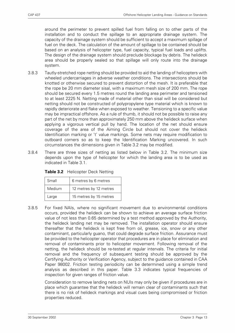
3.8.4 There are three sizes of netting as listed below in Table 3.2. The minimum sizedepends upon the type of helicopter for which the landing area is to be used asindicated in Table 3.1.
3.8.5 For fixed NAIs, where no significant movement due to environmental conditionsoccurs, provided the helideck can be shown to achieve an average surface frictionvalue of not less than 0.65 determined by a test method approved by the Authority,the helideck landing net may be removed. The installation operator should ensurethereafter that the helideck is kept free from oil, grease, ice, snow or any othercontaminant, particularly guano, that could degrade surface friction. Assurance mustbe provided to the helicopter operator that procedures are in place for elimination andremoval of contaminants prior to helicopter movement. Following removal of thenetting, the helideck should be re-tested at regular intervals. The criteria for initialremoval and the frequency of subsequent testing should be approved by theCertifying Authority or Verification Agency, subject to the guidance contained in CAAPaper 98002. Friction testing periodicity can be determined using a simple trendanalysis as described in this paper. Table 3.3 indicates typical frequencies ofinspection for given ranges of friction value.
Consideration to remove landing nets on NUIs may only be given if procedures are inplace which guarantee that the helideck will remain clear of contaminants such thatthere is no risk of helideck markings and visual cues being compromised or frictionproperties reduced.
Table 3.2 Helicopter Deck Netting
Small 6 metres by 6 metres
Medium 12 metres by 12 metres
Large 15 metres by 15 metres
Chapter 3 Page 1330 September 2002
CAP 437 Offshore Helicopter Landing Areas - Guidance on Standards
Landing nets on Mobile Installations have generally, in the absence of any research,been regarded as essential. However, it may be possible to present a Safety Case toBHAB for specific installations. The Safety Case must consider pitch, roll and heavelimitations and will require flight testing and a certain amount of research work.
NOTE: See also Cranfield University (College of Aeronautics) Paper FS–2191
3.8.6 Recent experience has shown that the removal of landing nets on some installationshas provided undesirable side-effects. Although the landing net was designedspecifically to enhance the friction properties of helideck surfaces, it would appearthat its textural properties can also provide pilots with a rich set of visual cues in termsof rate of closure and lateral movement which are essential for pilots in what canotherwise be a poor cueing environment. Serious consideration must be given to thisaspect before a landing net is removed. The helicopter operator should be consultedbefore existing landing nets are removed and Installation operators should beprepared to replace landing nets if so advised by the helicopter operator in the casethat visual cueing difficulties exist. For these reasons it is also recommended that thedesign of new Installations should incorporate the provision of landing net fittingsregardless of the type of friction surface to be provided.
3.9 Helicopter Tie-Down Points
3.9.1 Sufficient flush fitting (when not in use) or removable semi-recessed tie-down pointsshould be provided for securing the maximum sized helicopter for which the helideckis designed. They should be so located and be of such strength and construction tosecure the helicopter when subjected to weather conditions pertinent to theinstallation design considerations. They should also take into account, wheresignificant, the inertial forces resulting from the movement of floating units.
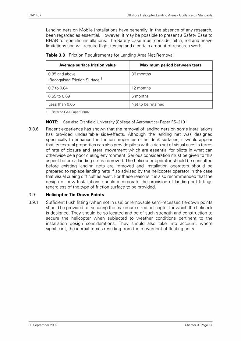
Table 3.3 Friction Requirements for Landing Area Net Removal
Average surface friction value Maximum period between tests
0.85 and above(Recognised Friction Surface)1
1. Refer to CAA Paper 98002
36 months
0.7 to 0.84 12 months
0.65 to 0.69 6 months
Less than 0.65 Net to be retained
Chapter 3 Page 1430 September 2002
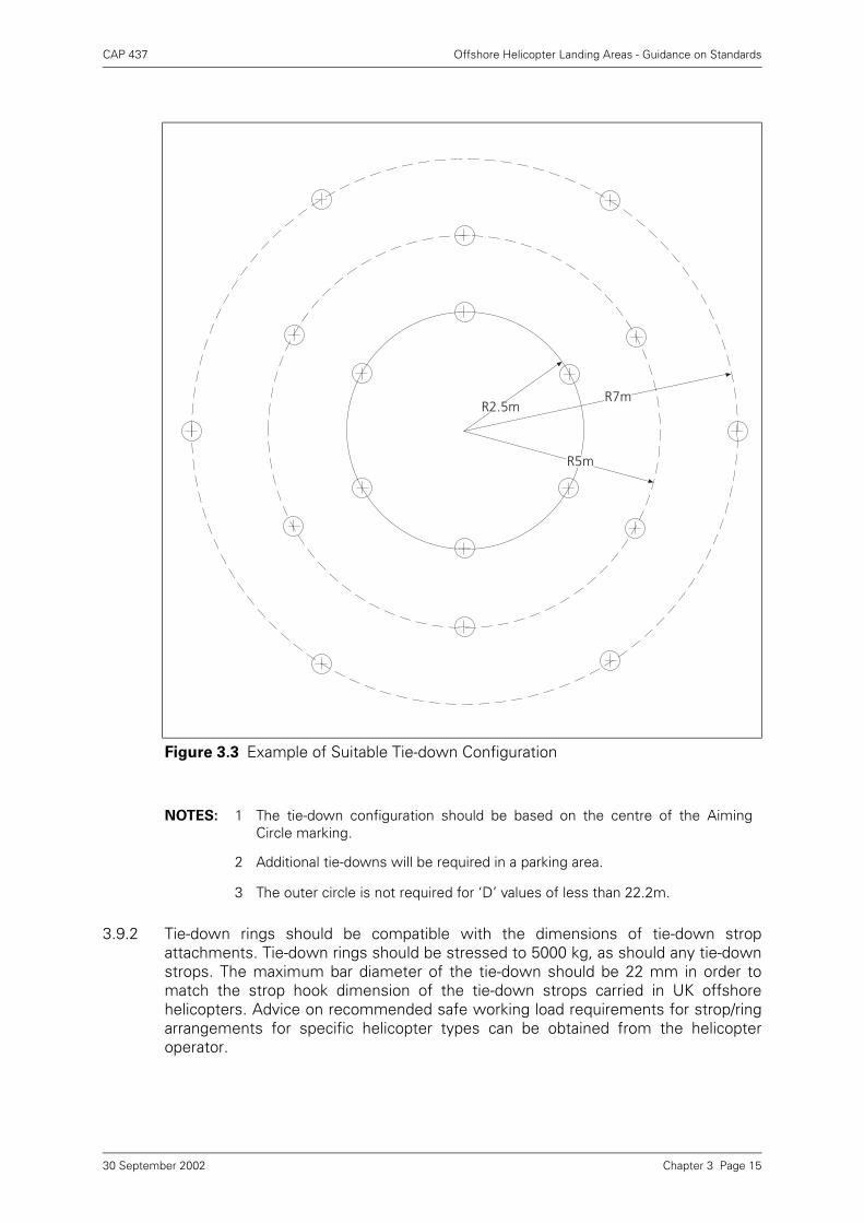
CAP 437 Offshore Helicopter Landing Areas - Guidance on Standards
3.9.2 Tie-down rings should be compatible with the dimensions of tie-down stropattachments. Tie-down rings should be stressed to 5000 kg, as should any tie-downstrops. The maximum bar diameter of the tie-down should be 22 mm in order tomatch the strop hook dimension of the tie-down strops carried in UK offshorehelicopters. Advice on recommended safe working load requirements for strop/ringarrangements for specific helicopter types can be obtained from the helicopteroperator.
Figure 3.3 Example of Suitable Tie-down Configuration
NOTES: 1 The tie-down configuration should be based on the centre of the AimingCircle marking.
2 Additional tie-downs will be required in a parking area.
3 The outer circle is not required for ‘D’ values of less than 22.2m.
R7m
R5m
R2.5m
Chapter 3 Page 1530 September 2002
CAP 437 Offshore Helicopter Landing Areas - Guidance on Standards
3.9.3 An example of a suitable tie-down configuration is shown at Figure 3.3. The BHAB willprovide guidance on the configuration of the tie-down points for specific helicoptertypes.
3.10 Safety Net
3.10.1 Safety nets for personnel protection should be installed around the landing areaexcept where adequate structural protection against falls exists. The netting usedshould be of a flexible nature, with the inboard edge fastened level with, or justbelow, the edge of the helicopter landing deck. The net itself should extend 1.5metres in the horizontal plane and be arranged so that the outboard edge is slightlyabove the level of the landing area, but by not more than 0.25 metres, so that it hasan upward and outward slope of at least 10°. The net should be strong enough towithstand and contain, without damage, a 75 kg weight being dropped from a heightof 1 metre.
3.10.2 A safety net designed to meet these criteria should not act as a trampoline giving a‘bounce’ effect. Where lateral or longitudinal centre bars are provided to strengthenthe net structure they should be arranged and constructed to avoid causing seriousinjury to persons falling on to them. The ideal design should produce a ‘hammock’effect which should securely contain a body falling, rolling or jumping into it, withoutserious injury. When considering the securing of the net to the structure and thematerials used, care must be taken that each segment will meet adequacy of purposeconsiderations. Polypropylene deteriorates over time; various wire meshes havebeen shown to be suitable if properly installed.
3.11 Access Points
3.11.1 Many helicopters have passenger access on one side only and helicopter landingorientation in relation to landing area access points becomes important because it isnecessary to ensure that embarking and disembarking passengers are not required topass around the helicopter tail rotor, or under the main rotor of those helicopters witha low profile rotor, when a ‘rotors-running turn-round’ is conducted (in accordancewith normal offshore operating procedures).
3.11.2 There should be a minimum of two access/egress routes to the helideck. Thearrangements should be optimised to ensure that, in the event of an accident orincident on the helideck, personnel will be able to escape upwind of the landing area.Adequacy of the emergency escape arrangements from the helideck should beincluded in any evacuation, escape and rescue analysis for the installation, and mayrequire a third escape route to be provided.
3.11.3 The need to preserve, in so far as possible, an unobstructed falling 5:1 gradient (seeparagraphs 3.7.5 and 3.7.6 above) and the provision of up to three helideck access/escape routes, with associated platforms, may present a conflict of requirements. Acompromise may therefore be required between the size of the platformcommensurate with its effectiveness and the need to retain the protection of anunobstructed falling 5:1 gradient. In practice, the 5:1 gradient is taken from theoutboard edge of the helideck perimeter safety net supports. Emergency accesspoints which extend outboard from the perimeter safety net constitute a compromisein relation to an unobstructed falling 5:1 gradient which may lead, in some instances,to the imposition of helicopter operating limitations. It is therefore important toconstruct access point platforms in such a manner as to infringe the falling 5:1gradient by the smallest possible amount but preferably not at all. Suitable positioningof two major access points clear of the requirements of the protection of the falling5:1 gradient should always be possible. However, the third access referred to atparagraph 3.11.2 will probably lie within the falling 5:1 sector and where this is the
Chapter 3 Page 1630 September 2002
CAP 437 Offshore Helicopter Landing Areas - Guidance on Standards
case it should be constructed within the dimensions of the helideck perimeter safetynet supports (i.e. contained within 1.5 metres of the edge of the landing area).
3.11.4 Where foam monitors are co-located with access points care should be taken wherepossible to ensure that no monitor is so close to an access point as to cause injury toescaping personnel by operation of the monitor in an emergency situation.
3.11.5 Where handrails associated with helideck access/escape points exceed the heightlimitations given at paragraph 3.7.2 they should be retractable, collapsible orremovable. When retracted, collapsed or removed the rails should not impedeaccess/egress. Handrails which are retractable, collapsible and removable should bepainted in a contrasting colour scheme. Procedures should be in place to retract,collapse, or remove them prior to helicopter arrival. Once the helicopter has landed,and the crew have indicated that passenger movement may commence (see Notebelow), the handrails may be raised and locked in position. The handrails must beretracted, collapsed, or removed again prior to the helicopter taking-off.
NOTE: The helicopter crew will switch off the anti-collision lights to indicate that themovement of passengers and/or freight may take place (under the control of theHLO). Installation/Vessel safety notices placed on approach to the helideck accessshould advise personnel not to approach the helicopter when the anti-collision lightsare on.
3.12 Winching Operations
It should be noted that for any installation or vessel, attended or unattended, fixed ormobile for which helicopters are a normal mode of transport for personnel, ahelicopter landing area should be provided. Winching should not be adopted as anormal method of transfer. However, if winching operations are required, they shouldbe conducted in accordance with procedures agreed between the helicopter operatorand the Authority and contained within the Helicopter Operator’s Operations Manual.Requirements for winching operations should be discussed with the specifichelicopter operator well in advance.
3.13 Normally Unattended Installations
3.13.1 The CAA provides guidance for helicopter operators on the routeing of helicoptersintending to land on NUIs. The CAA will also provide such guidance and advice tohelicopter operators and installation operators in consideration of specific InstallationSafety Cases and risk analyses which address routeing philosophy.
3.13.2 Guano and associated bird debris is a major problem for NUIs. Associated problemsconcern the health hazard on board; degradation of visual aids (markings and lighting)and friction surfaces; and the potential for FOD. Helicopter operators should monitorthe state of NUI helidecks and advise the owner/operator before markings andlighting degradation becomes a safety concern. Experience has shown that, unlessadequate cleaning operations are undertaken or effective preventative measures arein place, essential visual aids will quickly become obliterated. NUIs should bemonitored continuously for signs of degradation of visual cues and flights should notbe undertaken to helidecks where essential visual cues for landing are insufficient.
3.13.3 Guano is an extremely effective destroyer of friction surfaces whenever it is allowedto remain. Because of the difficulty of ensuring that a friction surface is kept clear ofcontaminants (see paragraph 3.8.5 above), permanent removal of the landing net onNUIs is not normally a viable option unless effective preventative measures are inplace.
Chapter 3 Page 1730 September 2002
CAP 437 Offshore Helicopter Landing Areas - Guidance on Standards
Chapter 4 Visual Aids
4.1 General
4.1.1 The name of the installation should be clearly displayed in such positions on theinstallation so that it can be readily identified from the air and sea from all normalangles and directions of approach. For identification from the air the helideck nameand the side identification panels are used. It is not necessary, neither is it a legalrequirement, to complicate recognition processes by inclusion of ‘Block Numbers’,Company logos, or other designators. In fact, complication of identifiers can beconfusing and will unnecessarily, and undesirably, extend the mental process ofrecognition at the critical time when the pilots’ concentration is being maximised bythe demands of the landing manoeuvre. The names on both identification markingsshould be identical, simple and unique and provide for unambiguous understandingon the radio. The approved radio callsign of the installation should be the same nameas the helideck and side panel identifier. Where the inclusion of ‘block numbers’ onside identification panels is deemed to be essential (i.e. for purposes other than
recognition), the name of the installation should also be included; e.g. ‘NAME.BLOCK NO.’ The installation identification panels should be highly visible in all lightconditions. They should be suitably illuminated at night and in conditions of poorvisibility. In order to minimise the possibility of ‘wrong rig landings’ use of newtechnology should be made so that identification can be confirmed in the early stagesof the approach (say out to 600 metres) by day and night. Modern technology iscapable of providing such brightness in most ambient conditions. Use of high-intensity cluster LED or fibre-optic systems in other applications have been shown tobe effective even in severely reduced visibility. Sole reliance on retro-reflectivesignage for side identification panels has been shown to be generally ineffective forearly recognition by flight crews at night and in poor visibility. (HSE Operations Notice39, dated December 1997, also refers).
4.1.2 Helideck markings (specifically the installation identification marking) and sideidentification panels are used by pilots to obtain a final pre-landing confirmation thatthe correct helideck has been selected. It is therefore VITAL that the helideckmarkings and side identification panels are maintained in the best possible condition,regularly re-painted and kept free of all visibility-reducing contaminants. Helideckowners/operators should ensure that specific inspection and re-painting maintenanceprocedures and schedules for helideck markings and side identification panels takeaccount of the importance of their purpose. Side identification panels should be keptfree of any obscuring paraphernalia (draped hoses etc.) and be as high as possible onthe structure.
4.1.3 The installation identification (see paragraphs 4.1.1 and 4.1.2) should be marked onthe helideck surface between the origin of the obstacle-free sector and the aimingcircle in symbols not less than 1.2 metres high and in a colour (normally white) whichcontrasts with the background. The name should not be covered by the deck netting.Where there is insufficient space to place the helideck marking in this position, themarking position shall be agreed with BHAB. See also Chapter 3, paragraph 3.8.3.
4.1.4 Helideck perimeter line marking and lighting serves to identify the limits of the SafeLanding Area (SLA – see Glossary) for day and night operations.
4.1.5 A wind direction indicator (windsock) should be provided and located so as to indicatethe (clean) area wind conditions at the installation/vessel location. It is ofteninappropriate to locate the windsock as close to the helideck as possible where it may
Chapter 4 Page 130 September 2002
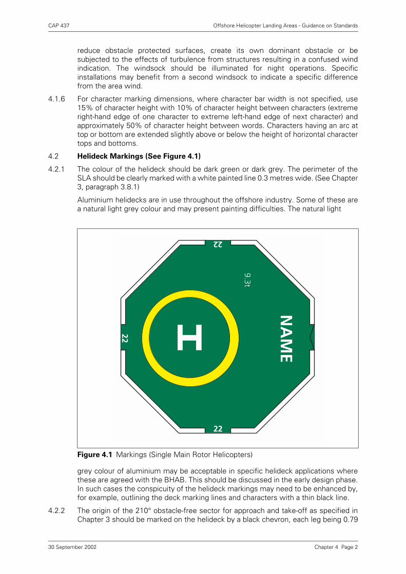
CAP 437 Offshore Helicopter Landing Areas - Guidance on Standards
reduce obstacle protected surfaces, create its own dominant obstacle or besubjected to the effects of turbulence from structures resulting in a confused windindication. The windsock should be illuminated for night operations. Specificinstallations may benefit from a second windsock to indicate a specific differencefrom the area wind.
4.1.6 For character marking dimensions, where character bar width is not specified, use15% of character height with 10% of character height between characters (extremeright-hand edge of one character to extreme left-hand edge of next character) andapproximately 50% of character height between words. Characters having an arc attop or bottom are extended slightly above or below the height of horizontal charactertops and bottoms.
4.2 Helideck Markings (See Figure 4.1)
4.2.1 The colour of the helideck should be dark green or dark grey. The perimeter of theSLA should be clearly marked with a white painted line 0.3 metres wide. (See Chapter3, paragraph 3.8.1)
Aluminium helidecks are in use throughout the offshore industry. Some of these area natural light grey colour and may present painting difficulties. The natural light
grey colour of aluminium may be acceptable in specific helideck applications wherethese are agreed with the BHAB. This should be discussed in the early design phase.In such cases the conspicuity of the helideck markings may need to be enhanced by,for example, outlining the deck marking lines and characters with a thin black line.
4.2.2 The origin of the 210° obstacle-free sector for approach and take-off as specified inChapter 3 should be marked on the helideck by a black chevron, each leg being 0.79
Figure 4.1 Markings (Single Main Rotor Helicopters)
NA
ME
22
22
22
9.3t
Chapter 4 Page 230 September 2002
CAP 437 Offshore Helicopter Landing Areas - Guidance on Standards
metres long and 0.1 metres wide forming the angle in the manner shown in Figure4.2. On mimimum sized helidecks where there is no room to place the chevron, thechevron marking, but not the point of origin, may be displaced towards the D circlecentre. The BHAB must be consulted in situations where this is necessary. Where theobstacle-free sector is swung in accordance with the provision of Chapter 3 paragraph3.7.3 this should be reflected in the alignment of the chevron. The purpose of thechevron is to provide visual guidance to the HLO so that he can ensure that the 210°OFS is clear of obstructions before giving a helicopter clearance to land. The blackchevron can be painted on top of the (continuous) white perimeter line to achievemaximum clarity for the helideck crew.
The actual D-value of the helideck (See Chapter 3, paragraph 3.7.1) should be paintedon the helideck inboard of the chevron in alphanumeric symbols of 0.1 metres high.Where a helideck has been accepted which does not meet the normal obstacle-freesector requirements of 210°, the black chevron should represent the angle which hasbeen accepted and this value should be marked inboard of the chevron in a similarmanner to the certificated D-value.
The helideck D-value should also be marked around the perimeter of the helideck inthe manner shown in Figure 4.1 in a colour contrasting (preferably white: avoid blackor grey for night use) with the helideck surface. The D-value should be to the nearestwhole number with 0.5 rounded down e.g. 18.5 marked as 18. Helidecks designedspecifically for AS332L2 helicopters should be rounded up to 20 in order todifferentiate between helidecks designed specifically for L1 models.
4.2.3 A maximum allowable weight marking should be marked on the helideck in a positionwhich is readable from the preferred final approach direction i.e. towards theobstacle-free sector origin. The marking should consist of a two digit number followedby the letter ‘t’ to indicate the allowable helicopter weight in tonnes (1000 kg). Theheight of the figures should be 0.9 metres with a line width of approximately 0.12metres and be in a colour which contrasts with the helideck surface (preferably white:avoid black or grey). Where possible the weight marking should be well separatedfrom the installation identification marking (see paragraph 4.1.1) in order to avoidpossible confusion on recognition. Refer also to Figure 4.1 and Chapter 3 paragraph3.8.3 and Table 3.1.
4.2.4 Aiming circles should be provided as follows: (see Figures 4.1 and 4.3).
The marking should be a yellow circle with an inner diameter of 0.5 of the certificatedD-value of the helideck and a line width of 1 metre. Its centre should be located 0.1D from the centre of the D circle towards the outboard edge of the helideck on thebisector of the obstacle-free sector in order to achieve an increased safety margin fortail rotor clearance. On smaller helidecks and bow-mounted helidecks on vesselsthere is a case for making the aiming circle concentric with the helideck centre toensure that there is a maximisation of space all round for safe personnel movementand an enhanced visual cueing environment. (See Figure 4.3).
Chapter 4 Page 330 September 2002
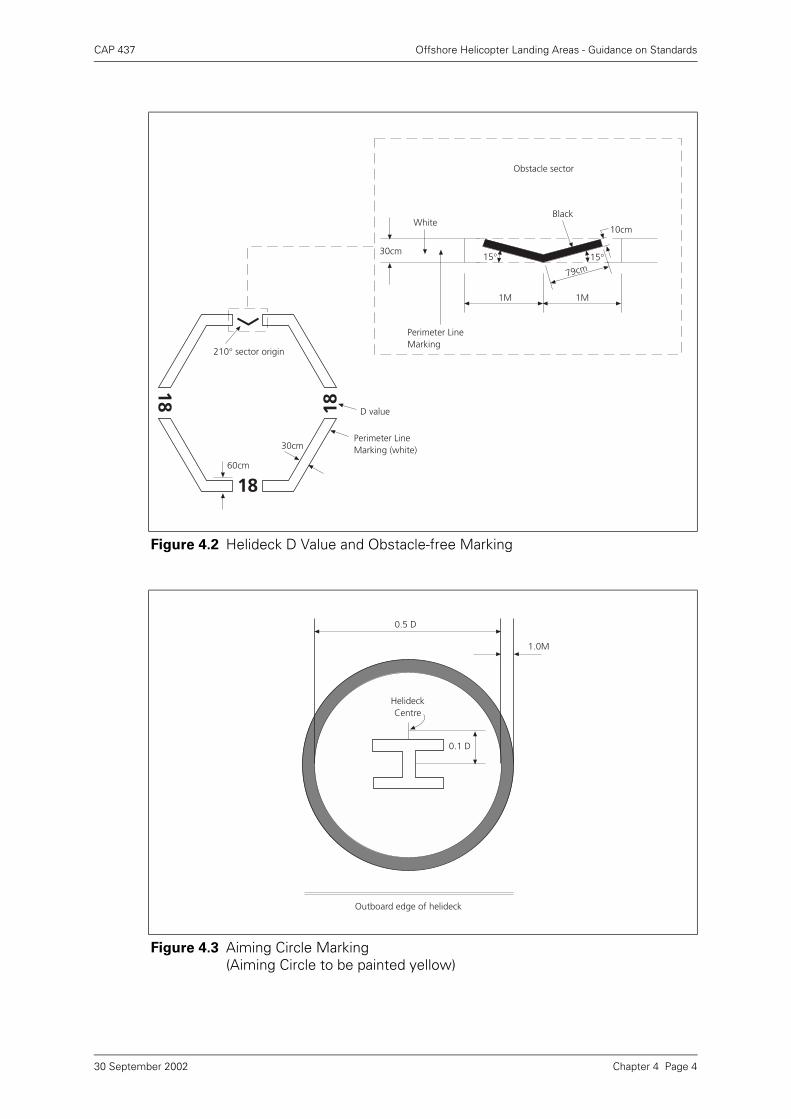
CAP 437 Offshore Helicopter Landing Areas - Guidance on Standards
Figure 4.2 Helideck D Value and Obstacle-free Marking
Figure 4.3 Aiming Circle Marking(Aiming Circle to be painted yellow)
30cm
18
18
1860cm
210° sector origin
D value
Perimeter LineMarking (white)
White
30cm
Perimeter LineMarking
1M 1M
Black
79cm
10cm
15°15°
Obstacle sector
0.5 D
HelideckCentre
0.1 D
Outboard edge of helideck
1.0M
Chapter 4 Page 430 September 2002
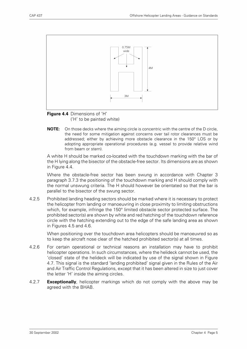
CAP 437 Offshore Helicopter Landing Areas - Guidance on Standards
NOTE: On those decks where the aiming circle is concentric with the centre of the D circle,the need for some mitigation against concerns over tail rotor clearances must beaddressed; either by achieving more obstacle clearance in the 150° LOS or byadopting appropriate operational procedures (e.g. vessel to provide relative windfrom beam or stern).
A white H should be marked co-located with the touchdown marking with the bar ofthe H lying along the bisector of the obstacle-free sector. Its dimensions are as shownin Figure 4.4.
Where the obstacle-free sector has been swung in accordance with Chapter 3paragraph 3.7.3 the positioning of the touchdown marking and H should comply withthe normal unswung criteria. The H should however be orientated so that the bar isparallel to the bisector of the swung sector.
4.2.5 Prohibited landing heading sectors should be marked where it is necessary to protectthe helicopter from landing or manoeuvring in close proximity to limiting obstructionswhich, for example, infringe the 150° limited obstacle sector protected surface. Theprohibited sector(s) are shown by white and red hatching of the touchdown referencecircle with the hatching extending out to the edge of the safe landing area as shownin Figures 4.5 and 4.6.
When positioning over the touchdown area helicopters should be manoeuvred so asto keep the aircraft nose clear of the hatched prohibited sector(s) at all times.
4.2.6 For certain operational or technical reasons an installation may have to prohibithelicopter operations. In such circumstances, where the helideck cannot be used, the‘closed’ state of the helideck will be indicated by use of the signal shown in Figure4.7. This signal is the standard ‘landing prohibited’ signal given in the Rules of the Airand Air Traffic Control Regulations, except that it has been altered in size to just coverthe letter ‘H’ inside the aiming circles.
4.2.7 Exceptionally, helicopter markings which do not comply with the above may beagreed with the BHAB.
Figure 4.4 Dimensions of ‘H’(‘H’ to be painted white)
4M
0.75Mwide
3M
Chapter 4 Page 530 September 2002
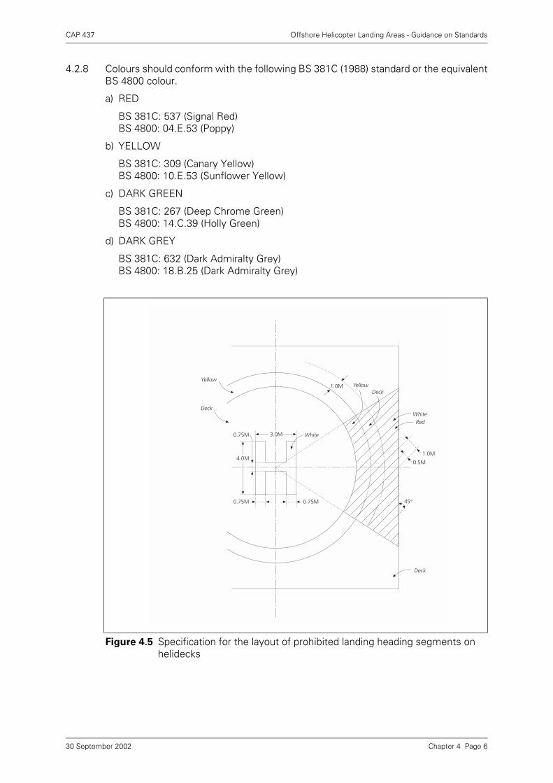
CAP 437 Offshore Helicopter Landing Areas - Guidance on Standards
4.2.8 Colours should conform with the following BS 381C (1988) standard or the equivalentBS 4800 colour.
a) RED
BS 381C: 537 (Signal Red)BS 4800: 04.E.53 (Poppy)
b) YELLOW
BS 381C: 309 (Canary Yellow)BS 4800: 10.E.53 (Sunflower Yellow)
c) DARK GREEN
BS 381C: 267 (Deep Chrome Green)BS 4800: 14.C.39 (Holly Green)
d) DARK GREY
BS 381C: 632 (Dark Admiralty Grey)BS 4800: 18.B.25 (Dark Admiralty Grey)
Figure 4.5 Specification for the layout of prohibited landing heading segments on helidecks
Yellow
Deck
White
0.75M 0.75M
0.75M
4.0M
3.0M
DeckYellow
RedWhite
1.0M
0.5M
45°
1.0M
Deck
Chapter 4 Page 630 September 2002
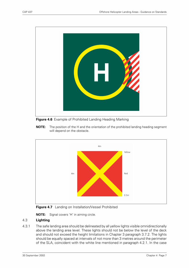
CAP 437 Offshore Helicopter Landing Areas - Guidance on Standards
NOTE: The position of the H and the orientation of the prohibited landing heading segmentwill depend on the obstacle.
NOTE: Signal covers ‘H’ in aiming circle.
4.3 Lighting
4.3.1 The safe landing area should be delineated by all yellow lights visible omnidirectionallyabove the landing area level. These lights should not be below the level of the deckand should not exceed the height limitations in Chapter 3 paragraph 3.7.2. The lightsshould be equally spaced at intervals of not more than 3 metres around the perimeterof the SLA, coincident with the white line mentioned in paragraph 4.2.1. In the case
Figure 4.6 Example of Prohibited Landing Heading Marking
Figure 4.7 Landing on Installation/Vessel Prohibited
4m
4m
Yellow
Red
0.5m
Chapter 4 Page 730 September 2002
CAP 437 Offshore Helicopter Landing Areas - Guidance on Standards
of square or rectangular decks there should be a minimum of four lights at each sideincluding a light at each corner of the safe landing area.The yellow lights should be ofat least 25 candelas intensity. Higher intensity lighting can be of assistance inconditions of poor visibility in daylight, but where such lighting is fitted it shouldincorporate a brilliance control to reduce the intensity to the values quoted for nightuse. Flush fitting lights or Electroluminescent panels may be used at the inboard (150°LOS origin) edge of the SLA.
4.3.2 Where the declared D-value of the helideck is less than the physical helideck area, theperimeter lights should delineate the limit of the safe landing area so that thehelicopter could land by reference to the perimeter lights on the limited obstaclesector (LOS -150°) side of the helideck without risk of main rotor collision withobstructions in this sector. By applying the LOS clearances from the perimetermarking, which are given at Chapter 3 paragraph 3.7.4, adequate main rotor toobstruction separation should be achieved. A suitable temporary arrangemnent tomodify the lighting delineation of the SLA, where this is found to be marked toogenerously, can be agreed with the BHAB by replacing existing yellow lights with redlights of 25 candelas around the ‘unsafe’ portion of the SLA. The perimeter line,however, should be repainted in the correct position immediately. Use of flush fittinglights or Electro-luminescent panels in the 150° sector perimeter will provideadequate illumination whilst affording minimum obstruction to personnel andequipment movement.
4.3.3 The landing area should also be floodlit if intended for night use. The floodlightingshould be arranged so as not to dazzle the pilot and, if elevated and located off thelanding area, the system should not present a hazard to helicopters landing or taking-off and should be clear of the LOS. Such floodlights should be capable of beingswitched on and off at the pilot’s request. The average illuminance should be at least10 lux with a uniformity ratio (average to minimum) of not more than 8 to 1. Settingup of the lights must be undertaken with care to ensure that the luminosity and anti-dazzle issues are properly addressed and regularly checked. It may be necessary toenhance the lighting to improve depth perception, possibly by using discretefloodlighting of the main structure or ‘legs’. One of the problems associated withmajor platforms and flotels etc., is that there is too much undirected, and thereforeunnecessary, light from the main installation ‘polluting’ the helideck area. Thehelideck lighting may meet the required specification but will appear to be in a ‘blackhole’ compared with the higher levels of other installation lighting. Installations shouldbe aware of this phenomena (‘Light Pollution’) and lights not necessary for helicopteroperations should, where possible, be shielded from the helideck. Adequate shieldingof helideck polluting light sources can be achieved in the early design stage and canalso be minimised on existing installations by simple measures. Temporary workinglights which pollute the helideck lighting environment should be switched off forhelicopter operations.
4.3.4 It is also important to confine the helideck lighting to the landing area, since any lightoverspill may cause reflections from the sea. The floodlighting controls should becontrolled by, and be readily accessible to, the HLO or Radio Operator.
4.3.5 The quoted intensity values for lights apply to the intensity of the light emitted fromthe unit when fitted with all necessary filters and shades (see also paragraph 4.4below).
4.3.6 If a condition can exist on an installation which may be hazardous for the helicopteror its occupants a visual warning system should be installed. The system (StatusLights) should be a flashing red light (or lights) which is visible to the pilot from anydirection of approach and on any landing heading. The aeronautical meaning of a
Chapter 4 Page 830 September 2002
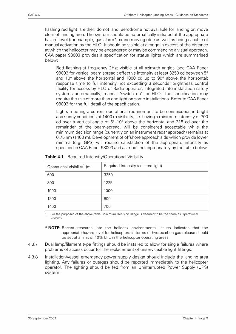
CAP 437 Offshore Helicopter Landing Areas - Guidance on Standards
flashing red light is either; do not land, aerodrome not available for landing or; moveclear of landing area. The system should be automatically initiated at the appropriatehazard level (for example, gas alarm*, crane moving etc.) as well as being capable ofmanual activation by the HLO. It should be visible at a range in excess of the distanceat which the helicopter may be endangered or may be commencing a visual approach.CAA paper 98003 provides a specification for status lights which are summarisedbelow:
Red flashing at frequency 2Hz; visible at all azimuth angles (see CAA Paper98003 for vertical beam spread); effective intensity at least 3250 cd between 5°and 10° above the horizontal and 1000 cd up to 90° above the horizontal;response time to full intensity not exceeding 3 seconds; brightness controlfacility for access by HLO or Radio operator; integrated into installation safetysystems automatically; manual ‘switch on’ for HLO. The specification mayrequire the use of more than one light on some installations. Refer to CAA Paper98003 for the full detail of the specification.
Lights meeting a current operational requirement to be conspicuous in brightand sunny conditions at 1400 m visibility; i.e. having a minimum intensity of 700cd over a vertical angle of 5°–10° above the horizontal and 215 cd over theremainder of the beam-spread, will be considered acceptable while theminimum decision range (currently on an instrument radar approach) remains at0.75 nm (1400 m). Development of offshore approach aids which provide lowerminima (e.g. GPS) will require satisfaction of the appropriate intensity asspecified in CAA Paper 98003 and as modified appropriately by the table below.
* NOTE: Recent research into the helideck environmental issues indicates that theappropriate hazard level for helicopters in terms of hydrocarbon gas release shouldbe set at a limit of 10% LFL in the helicopter operating areas.
4.3.7 Dual lamp/filament type fittings should be installed to allow for single failures whereproblems of access occur for the replacement of unserviceable light fittings.
4.3.8 Installation/vessel emergency power supply design should include the landing arealighting. Any failures or outages should be reported immediately to the helicopteroperator. The lighting should be fed from an Uninterrupted Power Supply (UPS)system.
Table 4.1 Required Intensity/Operational Visibility
Operational Visibility1 (m)
1. For the purposes of the above table, Minimum Decision Range is deemed to be the same as Operational Visibility.
Required Intensity (cd – red light)
600 3250
800 1225
1000 1000
1200 800
1400 700
Chapter 4 Page 930 September 2002
CAP 437 Offshore Helicopter Landing Areas - Guidance on Standards
4.4 Obstacles – Marking and Lighting
4.4.1 Fixed obstacles which present a hazard to helicopters should be readily visible fromthe air. If a paint scheme is necessary to enhance identification by day, alternate blackand white, black and yellow, or red and white bands are recommended, not less than0.5 metres nor more than 6 metres wide. The colour should be chosen to contrastwith the background to the maximum extent. Paint colours should conform with thereferences at paragraph 4.2.8 above.
4.4.2 Obstacles to be marked in these contrasting colours include any lattice towerstructures and crane booms which are close to the helideck or the LOS boundary.Similarly, parts of the leg or legs of jack-up units adjacent to the landing area whichextend, or can extend, above it should also be marked in the same manner.
4.4.3 Omnidirectional red lights of at least 10 candelas intensity should be fitted at suitablelocations to provide the helicopter pilot with visual information on the proximity andheight of objects which are higher than the landing area and which are close to it orto the LOS boundary. This should apply, in particular, to all crane booms on theinstallation. Objects which are more than 15 metres higher than the landing areashould be fitted with intermediate red lights of the same intensity spaced at 10 metreintervals down to the level of the landing area (except where such lights would beobscured by other objects). It is often preferable for some structures such as flarebooms and towers to be illuminated by floodlights as an alternative to fitting theintermediate red lights, provided that the lights are arranged such that they willilluminate the whole of the structure and not dazzle the helicopter pilot. Sucharrangements should be discussed with the BHAB.
4.4.4 An omnidirectional red light of intensity 25 to 200 candelas should be fitted to thehighest point of the installation. Where this is not practicable (e.g. on top of flaretowers) the light should be fitted as near to the extremity as possible.
4.4.5 In the particular case of jack-up units, it is recommended that when the tops of thelegs are the highest points on the installation, they should be fitted withomnidirectional red lights of intensity 25 to 200 candelas. In addition the leg or legsadjacent to the helideck should be fitted with intermediate red lights of at least 10candelas at 10 metre intervals down to the level of the landing area. Sufficient lightsshould be fitted to provide omnidirectional visibility. As an alternative the legs may befloodlit providing the helicopter pilot is not dazzled.
4.4.6 Any ancillary structure within 1 kilometre of the landing area, and which is significantlyhigher than it, should be similarly fitted with red lights.
4.4.7 Red lights should be arranged so that the location of the objects which they delineateare visible from all directions above the landing area.
4.4.8 Installation/Vessel emergency power supply design should include all forms ofobstruction lighting. Any failures or outages should be reported immediately to thehelicopter operator. The lighting should be fed from an Uninterrupted Power Supply(UPS) system.
Chapter 4 Page 1030 September 2002
CAP 437 Offshore Helicopter Landing Areas - Guidance on Standards
Chapter 5 Helideck Rescue and Fire Fighting Facilities
5.1 Introduction
This Chapter gives guidance regarding provision of equipment; extinguishing media;personnel; training; and emergency procedures for offshore helidecks on installationsand vessels. For specific guidance related to NUI’s refer to UKOOA’s guidelines forHelicopter Operations to Normally Unattended Installations.
5.2 Key Design Characteristics – Principal Agent
A key aspect in the successful design for providing an efficient, integrated helideckrescue and fire fighting facility is a complete understanding of the circumstances inwhich it may be expected to operate. A helicopter accident, which results in a fuelspillage with wreckage and/or fire and smoke, has the capability to render some ofthe equipment inventory unusable or preclude the use of some passenger escaperoutes.
5.2.1 Delivery of fire fighting media to the helideck area at the appropriate application ratemust be achieved in the quickest possible time. The Authority strongly recommendsthat a delay of less than thirty seconds, measured from the time of incident to actualproduction at the required application rate, should be the objective.
5.2.2 Foam-making equipment must be located so as to ensure the uniform application offoam to any part of the Safe Landing Area (SLA) irrespective of the wind strength/direction or accident location. In this respect particular consideration should be givento the loss of a foam monitor.
5.2.3 Consideration must be given to the effects of the weather on static equipment. Allequipment forming part of the facility should be designed to withstand protractedexposure to the elements or be protected from them. Where protection is the chosenoption, it must not prevent the equipment being brought into use quickly andeffectively (see paragraph 5.2.2 above). The effects of condensation on storedequipment should be considered.
5.2.4 The minimum capacity of the foam production system will depend on the D-value ofthe deck, the foam application rate, the discharge rates of installed equipment and theexpected duration of application.
5.2.5 The application rate is dependant on the types of foam concentrate in use and thetypes of foam application equipment selected. For fires involving aviation kerosene,the International Civil Aviation Organization (ICAO) has produced a performance testwhich assesses and categorises the foam concentrate. Most foam concentratemanufacturers will be able to advise on the performance of their concentrate againstthis test. The Authority recommends that foam concentrates compatible withseawater and meeting performance level ‘B’ are used. These foams require aminimum application rate of 5.5 litres per square metre (of SLA) per minute.
Calculation of Application Rate: Example for a D-value 22.2 metre helideck.Application rate = 5.5 x x r2 (5.5 x 3.142 x 11.1 x 11.1) = 2129 litres per minute.
5.2.6 Given the remote location of helidecks the overall capacity of the foam system shouldexceed that necessary for initial extinction of any fire. Ten minutes dischargecapability is generally considered by the UK CAA to be reasonable.
Calculation of minimum operational stocks: Using the 22.2 metre example asshown in paragraph 5.2.5 above. A 1% foam solution discharged over 10 minutes atthe minimum application rate will require 2129 x 1% x 10 = 213 litres of foam
π
Chapter 5 Page 130 September 2002
CAP 437 Offshore Helicopter Landing Areas - Guidance on Standards
concentrate. A 3% foam solution discharged over 10 minutes at the minimumapplication rate will require 2129 x 3% x 10 = 639 litres of foam concentrate.
NOTE: Sufficient reserve foam stocks to allow for replenishment as a result of operation ofthe system during an incident, or following training or testing will also need to beheld.
5.2.7 Low expansion foam concentrates can generally be applied in either aspirated orunaspirated form. It should be recognised that whilst solution applied unaspiratedmay provide a quick knockdown of any fuel fire, aspiration, i.e. induction of air into thefoam solution by monitor or by hand controlled foam branch, gives enhancedprotection after extinguishment. Wherever non-aspirated foam equipment is selectedduring design, additional equipment capable of producing aspirated foam forconsolidation should be provided.
5.2.8 Hand controlled hose line(s) capable of applying water in a jet/spray pattern at aminimum of 250litres/min for cooling, or specific firefighting tactics should beprovided. Not all fires are capable of being accessed by monitors or on someoccasions the use of monitors alone may endanger passengers. Therefore, theprovision of hand controlled hose line(s) for the application of foam should also beprovided.
5.2.9 If life saving opportunities are to be maximised it is essential that all equipment shouldbe readily available on, or in the immediate vicinity of the helideck wheneverhelicopter operations are being conducted. All equipment should be located at pointshaving immediate access to the helicopter landing area. The location of the storagefacilities should be clearly indicated.
5.3 Use and Maintenance of Foam Equipment
5.3.1 Mixing of different concentrates in the same tank i.e. different either in make orstrength is generally unacceptable. Many different strengths of concentrate are onthe market. Any decision regarding selection must take account of the designcharacteristics of the foam system. It is important to ensure that foam containers andtanks are correctly labelled.
5.3.2 Induction equipment ensures that water and foam concentrate are mixed in thecorrect proportions. Settings of adjustable inductors, if installed, must correspondwith strength of concentrate in use.
5.3.3 All parts of the foam production system, including the finished foam, should be testedby a competent person on commisioning and annually thereafter. The tests shouldassess the performance of the system against original design expectations.
5.4 Complementary Media
While foam is considered the primary means of dealing with fires involving fuelspillages, the wide variety of fire incidents likely to be encountered during helicopteroperations – i.e. engine, avionic bays, transmission areas, hydraulics – may require theprovision of more than one type of complementary agent. Dry powder, carbon dioxideor halon are generally considered acceptable for this task although halon is nowsubject to various restrictions under the Montreal Protocol.
5.4.1 The UK CAA recommends the use of dry powder as the primary complementaryagent. The minimum capacity should be 45 kg. The dry powder system should havethe capacity to deliver the agent anywhere on the SLA at the recommended dischargerate of 1.35–2 kg/sec. Containers of sufficient capacity to allow continuous applicationof the agent should be provided.
Chapter 5 Page 230 September 2002
CAP 437 Offshore Helicopter Landing Areas - Guidance on Standards
5.4.2 Where the use of a gaseous agent as an additional complementary agent is deemednecessary by the duty holder, regard should be paid to the requirement to deliver thisagent to the seat of the fire. Because of the weather conditions prevalent in theUKCS, gaseous media are considered to be less effective than dry powder for mostapplications.
All offshore helicopters have integral engine fire protection systems (predominantlyHalon) and it is therefore considered that provision of foam as the principal agent plussuitable water/foam branch lines plus sufficient levels of dry powder will form thecore of the fire extinguishing system.
5.4.3 In the case of NUI’s reference can be made to the UKOOA guidelines ‘HelicopterOperations to Normally Unattended Installations’. However, serious considerationshould be given to the selection and provision of foam as the principal agent.
5.4.4 All applicators are to be fitted with a mechanism which allows them to be handcontrolled.
5.4.5 Dry chemical powder should be of the ‘foam compatible’ type.
5.4.6 The complementary agents should be sited so that they are readily available at alltimes.
5.4.7 Reserve stocks of complementary media to allow for replenishment as a result ofactivation of the system during an incident, or following training or testing should beheld.
5.5 The Management of Extinguishing Media Stocks
Consignments of extinguishing media should be used in delivery order to preventdeterioration in quality by prolonged storage.
5.5.1 The mixing of different types of foam concentrate may cause serious sludging andpossible malfunctioning of foam production systems. Unless evidence to the contraryis available it should be assumed that different types are incompatible. In thesecircumstances it is essential that the tank(s), pipework and pump (if fitted) arethoroughly cleaned and flushed prior to the new concentrate being introduced.
5.5.2 Consideration should be given to the provision of reserve stocks for use in training,testing and recovery from emergency use.
5.6 Rescue Equipment
In some circumstances, lives may be lost if simple ancillary rescue equipment is notreadily available.
5.6.1 The UK CAA strongly recommends the provision of at least the following equipment.
Sizes of equipment are not detailed but should be appropriate for the types ofhelicopter expected to use the facility.
Chapter 5 Page 330 September 2002
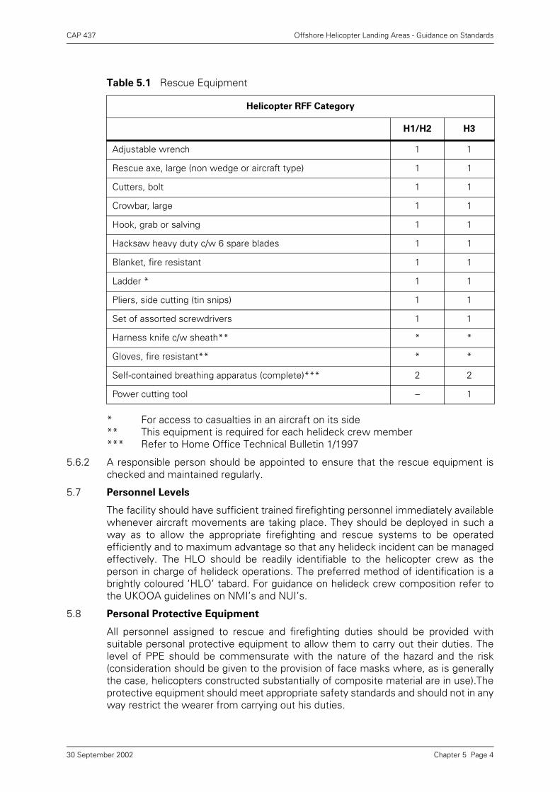
CAP 437 Offshore Helicopter Landing Areas - Guidance on Standards
* For access to casualties in an aircraft on its side** This equipment is required for each helideck crew member*** Refer to Home Office Technical Bulletin 1/1997
5.6.2 A responsible person should be appointed to ensure that the rescue equipment ischecked and maintained regularly.
5.7 Personnel Levels
The facility should have sufficient trained firefighting personnel immediately availablewhenever aircraft movements are taking place. They should be deployed in such away as to allow the appropriate firefighting and rescue systems to be operatedefficiently and to maximum advantage so that any helideck incident can be managedeffectively. The HLO should be readily identifiable to the helicopter crew as theperson in charge of helideck operations. The preferred method of identification is abrightly coloured ‘HLO’ tabard. For guidance on helideck crew composition refer tothe UKOOA guidelines on NMI’s and NUI’s.
5.8 Personal Protective Equipment
All personnel assigned to rescue and firefighting duties should be provided withsuitable personal protective equipment to allow them to carry out their duties. Thelevel of PPE should be commensurate with the nature of the hazard and the risk(consideration should be given to the provision of face masks where, as is generallythe case, helicopters constructed substantially of composite material are in use).Theprotective equipment should meet appropriate safety standards and should not in anyway restrict the wearer from carrying out his duties.
Table 5.1 Rescue Equipment
Helicopter RFF Category
H1/H2 H3
Adjustable wrench 1 1
Rescue axe, large (non wedge or aircraft type) 1 1
Cutters, bolt 1 1
Crowbar, large 1 1
Hook, grab or salving 1 1
Hacksaw heavy duty c/w 6 spare blades 1 1
Blanket, fire resistant 1 1
Ladder * 1 1
Pliers, side cutting (tin snips) 1 1
Set of assorted screwdrivers 1 1
Harness knife c/w sheath** * *
Gloves, fire resistant** * *
Self-contained breathing apparatus (complete)*** 2 2
Power cutting tool – 1
Chapter 5 Page 430 September 2002
CAP 437 Offshore Helicopter Landing Areas - Guidance on Standards
5.8.1 Sufficient personnel to operate the RFF equipment effectively should be dressed inprotective clothing prior to helicopter movements taking place.
5.8.2 The UK CAA recommends that at least two, positive pressure, self-containedbreathing apparatus sets complete with ancillary equipment plus two reservecylinders should be provided. These should be appropriately stored, readily availableclose to the helideck for fast deployment by the helideck crew.
5.8.3 Respiratory protective equipment enables the wearer to enter and work in anatmosphere which would not otherwise support life. It is therefore essential that it bestored, tested and serviced in such a way that it will ensure that it can be usedconfidently by personnel. Refer to the manufacturer’s instructions and to the HomeOffice Technical Bulletin 1/1997.
5.8.4 A responsible person(s) should be appointed to ensure that all personal protectiveequipment is installed, stored, used, checked and maintained in accordance with themanufacturer’s instructions.
5.9 Training
If they are to effectively utilise the equipment provided, all personnel assigned torescue and fire fighting duties on the helideck should be fully trained to carry out theirduties. The UK CAA recommends that personnel attend an established helicopter firefighting course.
In addition, regular training in the use of all RFF equipment, helicopter familiarisationand rescue tactics and techniques should be carried out. Correct selection and use ofprimary and complementary medias for specific types of incident should form anintegeral part of personnel training.
5.10 Emergency Procedures
The installation or vessel emergency procedures manual should specify the actionsto be taken in the event of an emergency involving a helicopter on or near theinstallation or vessel. Exercises designed specifically to test these procedures and theeffectiveness of the fire fighting teams should take place at regular intervals.
5.11 Further Advice
Advice is available from UK CAA Aerodrome Standards Department regarding thechoice and specification of fire extinguishing agents.
Chapter 5 Page 530 September 2002
CAP 437 Offshore Helicopter Landing Areas - Guidance on Standards
Chapter 6 Helicopter Landing Areas
– Miscellaneous Operational Standards
6.1 Landing Area Height Above Water Level
Because of the effects upon aircraft performance in the event of an engine failure(see Chapter 2) the height of the landing area above water level will be taken intoaccount by the BHAB in deciding on any operational limitations to be applied tospecific helidecks. Landing area height above water level is to be included in theinformation supplied to the BHAB for the purpose of authorising the use of thehelideck.
6.2 Wind Direction (Vessels)
Because the ability of a vessel to manoeuvre may be helpful in providing anacceptable wind direction in relation to the helideck location, information provided tothe BHAB is to include whether the vessel is normally fixed at anchor, single pointmoored, semi or fully manoeuvrable. The BHAB may specify windspeed and directionrequirements and limitations when authorising the use of the helideck.
6.3 Helideck Movement
6.3.1 Although helidecks located amidships are less liable to the extremes of vesselmovement experienced at bow or stern locations, a BHAB clearance will be relatedto the aircraft operator’s Operations Manual limitations regarding the movement ofthe helideck in pitch, roll, heave and heading. It is necessary for details of thesemotions to be recorded on the vessel prior to, and during, all helicopter movements.
6.3.2 Pitch and Roll reports to helicopters should include values, in degrees, about bothaxes of the true vertical datum (i.e. relative to the true horizon) and be expressed inrelation to the vessel’s head. Roll should be expressed in terms of ‘left’ and ‘right’;pitch should be expressed in terms of ‘up’ and ‘down’; heave should be reported in asingle figure, being the total heave motion of the helideck rounded up to the nearestmetre. Heave is to be taken as the vertical difference between the highest and lowestpoints of any single cycle of the helideck movement. The parameters reported shouldbe the maximum peak levels recorded during the ten minute period prior tocommencement of helicopter deck operations.
The helicopter pilot is concerned, in order to make vital safety decisions, with theamount of ‘slope’ on, and the rate of movement of, the helideck surface. It istherefore important that the Roll values are only related to the true vertical and do notrelate to any ‘false’ datum (i.e. a ‘list’) created, for example, by anchor patterns ordisplacement. There are circumstances in which a pilot can be aided by amplificationof the heave measurement by reference to the time period (seconds) in terms of‘peak to peak’.
6.3.3 Reporting Format:
A standard radio message should be passed to the helicopter which contains theinformation on helideck movement in an unambiguous format. This will, in mostcases, be sufficient to enable the helicopter crew to make safety decisions. Shouldthe helicopter crew require other motion information or amplification of the standardmessage, the crew will request this (for example, yaw and heading information).
Chapter 6 Page 130 September 2002
CAP 437 Offshore Helicopter Landing Areas - Guidance on Standards
Standard report example:
Situation: The maximum vessel movement (over the preceding ten minute period)about the Roll axis is 1° to port and 3° to starboard (i.e. this vessel may have apermanent list of 1° to starboard and is rolling a further 2° either side of this ‘false’datum). The maximum vessel movement (over the preceding ten minute period)about the pitch axis is 2° up and 2° down. The total maximum heave (recorded overthe preceding ten minute period) is 1.5 metres.
Report: ‘Roll 1° left and 3° right; Pitch 2° up and 2° down; heave two metres’.
6.3.4 Current research has indicated that vessel movement is complex in nature and ischaracterised by a number of parameters, some of which are not presently reported.It is therefore possible that future requirements will contain different measuring andreporting criteria. The Authority is currently carrying out research into themeasurement of the motion and acceleration forces of moving helidecks and theirimpact on the characteristics of helicopter aerodynamics and dynamics whilst on thedeck. A CAA Paper will be published in due course. Pending publication, it isconsidered useful to comment on some of the findings to date:
• It is important to measure helideck movement at the helideck. Very often pitch, rolland heave measurement is taken from a source far removed from the helidecklocation. If this source should happen to be midships and the helideck is locatedhigh up on the bow, the actual movement and acceleration forces at the helideckare likely to be far in excess of the source measurement. Software packages areavailable to provide helideck location corrected movement data from a source at adifferent location.
• Future guidance will advocate that deck motion measuring equipment will beplaced at (attached to the underside of) the helideck or compensated by softwareto give helideck location readings.
• The R & D project has already identified commercially available accelerometerpackages which can incorporate software which measures the importantparameters; produces a pich, roll and heave read out (maximum over preceding 10minutes); incorporates a prediction based on known weather patterns and vesselmotion characteristics that the deck will be safe for ground operations over thefollowing 10 minutes; and provides all this in a single figure Motion Severity Index(MSI) which will have a straight read-across to helicopter operators’ Manuals.
• The helicopter companies’ Operations Manuals will eventually contain a Limit ofOperability, based initially on a generic helicopter which covers the types in currentuse. It is intended that the given MSI will be easily referenced to the Operator’sLimit of Operability thus providing an unambiguous reporting and recordingsystem.
• Software packages reporting an MSI are also capable of measuring the valuesaccurately in pitch, roll and heave.
It has been noted that some moving helidecks reports to pilots are based on visualestimations. This is not an acceptable way of obtaining vital safety information. It istherefore strongly recommended that all moving helidecks are equipped withaccelerometer packages and the associated software which will not only enablefuture conversion to MSI readout but also produce accurate pitch, roll and heaveinformation for present day reporting requirements.
Chapter 6 Page 230 September 2002
CAP 437 Offshore Helicopter Landing Areas - Guidance on Standards
6.4 Aircraft Operational Data – Reporting and Recording
6.4.1 In addition to the data covered by paragraph 6.3 above, it is essential that allinstallations are provided with means of ascertaining and reporting at any time:
a) the wind speed and direction;
b) the air temperature;
c) the barometric pressure;
d) the visibility, cloud base and cover; and
e) the sea state.
6.4.2 Air temperature and barometric pressure can be measured by conventionalinstruments. An indication of wind speed and direction will be provided visually to thepilot by the provision of a windsock coloured so as to give maximum contrast with thebackground. However, for recording purposes, an anemometer positioned in anunrestricted airflow is required. A second anemometer, located at a suitable heightand position can give useful information on wind velocity at hover height over thehelideck in the event of turbulent or deflected airflows over the deck. Visibility andcloud conditions will normally be assessed by visual observations as will the seastate, although, on some of the larger installations wave crest to trough measuringinstruments are available as are cloud base and visibility measuring instruments.
6.4.3 Measuring instruments used to provide the data listed in paragraph 6.4.1 aboveshould be periodically calibrated in accordance with the manufacturer’srecommendations in order to provide continuing adequacy of purpose.
6.5 Location in Respect to Other Landing Areas in the Vicinity
6.5.1 Mobile installations and support vessels with helidecks may be positioned adjacentto other installations so that mutual interference/overlap of obstacle protectedsurfaces occur. Also on some installations there may be more than one helideckwhich may result in a confliction of obstacle free sectors.
6.5.2 Where there is confliction as mentioned above, within the obstacle free sector out to1000 metres, simultaneous operation of two helicopter landing areas is not to takeplace without prior consultation with the BHAB. It is possible, depending upon thedistance between landing areas and the operational conditions which may pertain,that simultaneous operation can be permitted but suitable arrangements fornotification of helicopter crews and other safety precautions will need to be arranged.In this context, ‘Flotels’ will be regarded in the same way as any other mobileinstallation which may cause mutual interference with the parent installationapproach and take-off sector. See also Chapter 3 above.
6.6 Control of Crane Movement in the Vicinity of Landing Areas
6.6.1 Cranes can adversely distract pilots’ attention during helicopter approach and take-offfrom the helideck as well as infringe fixed obstacle protected surfaces. Therefore it isessential that when helicopter movements take place (±5 mins) crane work ceasesand jibs, ‘A’ frames, etc. are positioned clear of the obstacle protected surfaces andflight paths.
6.6.2 The Helicopter Landing Officer should be responsible for the control of cranes inpreparation for and during helicopter operations.
Chapter 6 Page 330 September 2002
CAP 437 Offshore Helicopter Landing Areas - Guidance on Standards
6.7 General Precautions
6.7.1 Whenever a helicopter is stationary on board an offshore installation with its rotorsturning, no person shall, except in case of emergency, enter upon or move about thehelicopter landing area otherwise than within view of a crew member or the HLO andat a safe distance from its engine exhausts and tail rotor. It may be dangerous to passclose to the front of those helicopters which have a low main rotor profile.
6.7.2 The practical implementation of paragraph 6.7.1 above is best served throughconsultation with the helicopter operator for a clear understanding of the approachpaths approved for personnel and danger areas associated with a rotors-runninghelicopter. These areas are type-specific but, in general, the approved routes to andfrom the helicopter are at the 2–4 o’clock and 8–10 o’clock positions. Avoidance ofthe 12 o’clock (low rotor profile helicopters) and 6 o’clock (tail rotor danger areas)positions must be maintained.
6.7.3 Personnel must not approach the helicopter while the helicopter anti-collision(rotating/flashing) beacons are operating. In the offshore environment, the helideckshould be kept clear of all personnel while anti-collision lights are on.
6.8 Installation/Vessel Helideck Operations Manual and General Requirements
The maximum helicopter weight and ‘D’ value for which the deck has been designedand the maximum size and weight of helicopter for which the installation is certifiedshould be included in the Operations Manual. The extent of the obstacle-free areashould also be stated and reference made to any helideck operating limitationimposed by helicopter operators as a result of non-compliance. Non-compliancesshould also be listed.
6.9 Helicopter Operations Support Equipment
6.9.1 Provision should be made for equipment needed for use in connection with helicopteroperations including:
a) chocks and tie-down strops/ropes (strops are preferable);
b) heavy-duty, calibrated, accurate scales for passenger baggage and freightweighing;
c) a suitable power source for starting helicopters if helicopter shut-down is seen asan operational requirement; and
d) equipment for clearing the helicopter landing area of snow and ice and othercontaminants.
6.9.2 Chocks should be compatible with helicopter undercarriage/wheel configurations.Helicopter operating experience offshore has shown that the most effective chock foruse on helidecks is the ‘NATO sandbag’ type. Alternatively, ‘rubber triangular’ or‘single piece fore and aft’ type chocks may be used as long as they are suited to allhelicopters likely to operate to the helideck. The ‘rubber triangular’ chock is generallyonly effective on decks without nets.
6.9.3 For securing helicopters to the helideck it is recommended that adjustable tie-downstrops are used in preference to ropes. Specifications for tie-downs should be agreedwith BHAB.
6.9.4 It is essential that aeronautical radios are provided. Approval for this (and for Non-Directional Beacons) is to be sought from the Air Traffic Safety Standards Departmentat SRG, Gatwick. Northern North Sea radio procedures require two separate radios ontwo separate frequencies; one for ‘Traffic’ and one for ‘Logistics’. In addition the HLOshould have a portable radio tuned to the ‘Traffic’ frequency for the ‘landing clearance’
Chapter 6 Page 430 September 2002

CAP 437 Offshore Helicopter Landing Areas - Guidance on Standards
and ‘lifting’ calls; and tuned to ‘Logistics’ for logistic calls. It is recommended that allmobile installations and vessels used in support of oil/gas exploitation operations areequipped with two aeronautical radio sets. Ideally the power supply for theaeronautical radios should be fed from an Uninterrupted Power Supply (UPS) system.
Chapter 6 Page 530 September 2002
CAP 437 Offshore Helicopter Landing Areas - Guidance on Standards
Chapter 7 Helicopter Fuelling Facilities
7.1 General
The contents of this chapter and Chapter 8 are intended as general advice on therequirements necessary for the fuelling of helicopters on offshore installations andvessels. The information has been compiled by UKOOA in consultation with theOffshore Industry. More detailed information, if required, can be obtained fromaviation fuel suppliers. Civil Aviation Publications CAP 74 (Aircraft Fuelling: FirePrevention and Safety Measures) and CAP 434 (Aviation Fuel at Aerodromes) provideadditional general information and guidance. It is inevitable that in a document suchas this, the reader will be referred to British Standards or alternative guidance andexample. The reader should always check that standards and numbers so referencedare current and reflect current best practice.
7.1.1 It should be noted that offshore fuelling systems may vary according to the particularapplication for which it was designed. Nevertheless the elements of all systems willbasically be the same to include:
a) Transit tanks.
b) Storage facilities (see Note).
c) Delivery system.
NOTE: In some systems where built in tanks are not provided transit tanks are acceptablefor storage purposes.
7.1.2 Chapter 7 describes the features of a typical offshore fuelling system with additionalinformation on maintenance requirements and procedures. Chapter 8 provides adetailed guide on fuelling procedures. It should be noted that additional guidance onsafety measures concerning fuelling of helicopters can be obtained from CAP 74‘Aircraft Fuelling: Fire Prevention and Safety Measures’.
7.1.3 Particularly in the UK, many responsible bodies within the oil and helicopter industrieshave developed their own maintenance and inspection regimes and cycles. Theremay, therefore, appear to be anomalies between different source guidance on: filterelement replacement periodicity; hose inspection and replacement periodicity; staticstorage tank inspection periodicity and; bonding lead continuity checks. Alternative,responsible source guidance may be used where the user can satisfy himself that thealternative is adequate for the purpose considering particularly the hostile conditionsto which the systems may be subjected and the vital importance of a supply of cleanfuel.
7.2 Fuelling System Description
7.2.1 Transit Tanks
7.2.1.1 Transit tanks should be constructed to satisfy the requirements of theIntergovernmental Marine Consultative Organisation (IMCO), meeting the DangerousGoods Code Type 1 or Type 2 tank. They should also conform with BS 7072 (1989) –Inspection and Repair of Offshore Containers.
7.2.1.2 Tanks may be of stainless steel or mild steel; if the latter, then tanks must be linedwith suitable fuel resistant epoxy lining. The tanks must be encased in a robust steelcage with tie-down points and four main lifting eyes. Where possible, stainless steelfasteners, in conjunction with stainless steel fittings, are recommended. The tankframe should incorporate cross-members to provide an integral ‘ladder’ access to the
Chapter 7 Page 130 September 2002
CAP 437 Offshore Helicopter Landing Areas - Guidance on Standards
tank top. When mounted in the transit frame there should be a centre line slopetowards a small sump. This slope should be at least 1 in 30, although 1 in 25 ispreferred. Tanks should be clearly marked with the tank capacity and the type of fuelcontained. The tank’s serial number should also be permanently marked on theidentification plate. The tank should normally be fitted with the following:
a) Manhole. An 18” manhole to allow physical access to the interior of the tank.
b) Inspection Hatch. A 6” hatch to enable inspection of the low end of the tankcontents.
c) Dipstick Connection. A suitable captive dipstick to determine the tank contents,preferably of fibreglass material.
d) Emergency Pressure Relief. A stainless steel 2½” pressure/vacuum relief valvefitted with weatherproof anti-flash cowl. The valve settings will depend on the typeof tank in use, manufacturers’ recommendations should be followed.
e) Sample Connection. A stainless steel sample point, fitted at the lowest point ofthe tank. A foot-valve should be fitted in the sample line, complete with anextension pipe and terminating with a ball valve with captive dust cap. Sample linesmust be a minimum of ¾” diameter and preferably 1” diameter. In order to allowcorrect sample jars to be used, the sample point should be designed with sufficientaccess, space and height to accommodate the standard 4 litre sample jar.
f) Outlet/Fill Connection. The outlet/fill connection should be a flanged fitting witha 3” internal valve terminating to a 2½” self-sealing coupler complete with dustcap. The tank outlet should be at least 6” higher than the lowest point of the tank.
g) Frame. The tank barrel and frame should be suitably primed and then finished insafety yellow (BS 4800, Type 08E51). Safety yellow is not mandatory but has beengenerally accepted for helifuel tanks. All component parts e.g. tank, frame etc.must be properly bonded before being painted.
More detailed specification for transit tanks can be obtained on request from UKOOA.
7.2.2 Static Storage Tanks
Where static tanks are provided they should be constructed to suitable standards.Acceptable standards include ASME VIII and BS 5500 Categories I, II and III. The tankshould be mounted with a centre line slope to a small sump. This slope should be atleast 1 in 30, although 1 in 25 is preferred. The sump should be fitted with a sampleline which has both a gate valve and ball valve and should preferably have a captivecamlock dustcap on the end to prevent the ingress of dirt or moisture. Sample linesmust be a minimum of ¾” diameter and preferably 1” diameter. The sample pointaccessibility should be as described in paragraph 2.1.2 e) above. Static tanks shouldbe fitted with the following:
a) Manhole. A 24” minimum diameter manhole which should normally be hinged toassist easy opening.
b) Inspection Hatch. A 6” sample hatch to allow for a visual inspection of the lowend of the tank, or for the taking of samples.
c) Dipstick. A suitable captive dipstick to determine the tank contents, designed sothat it cannot bottom on the tank indicator and cause scratching, particularly inlined tanks. The dipstick should preferably be of fibreglass material.
d) Vent. A free vent, or an emergency pressure relief valve. When a pressure reliefvalve is fitted, the type and pressure settings should be in accordance with themanufacturer’s recommendations.
Chapter 7 Page 230 September 2002
CAP 437 Offshore Helicopter Landing Areas - Guidance on Standards
e) Outlet/Fill Connection. Separate outlet and fill connections with the fill pointarranged so that there is no free-fall of product at any stage of the tank filling. Theoutlet should either be by floating suction or from a stack pipe which extends atleast 6” above the lowest point of the tank. If a floating suction is embodied thena bonded floating suction check wire pull assembly should be fitted directly to thetop of the tank. A floating suction offers several advantages over a stack pipe outletand is therefore strongly recommended.
f) Contents Gauge. A sight glass or preferably a contents gauge.
g) Automatic Closure Valves. Automatic quick closure valves to the delivery andsuction inlet and outlets. These valves should be capable of operation from boththe helideck and from another point which is at a safe distance from the tank.
7.2.2.1 The static storage tank shell must be properly bonded and the entire tank externalsurface should preferably be finished in safety yellow paint (BS 4800, Type 08E51).Safety yellow is not mandatory but has been generally accepted for helifuel tanks.
7.3 Delivery System
The delivery system to transfer fuel from the storage tank to the aircraft must includethe following components:
a) Pump. The pump should be an electrically or air driven, centrifugal or positivedisplacement type with a head and flow rate suited to the particular installation.The pump should be able to deliver up to 50 IGPM under normal flow conditionsand to produce 50 psi no flow pressure, i.e. with the delivery nozzle closed. Aremote start/stop button must be provided on or immediately close to the helideckand close to the hose storage location. There should also be a pump runningwarning light which is visible from the helideck.
b) Filtration Units. Filter units including microfilters, filter water separators and fuelmonitors should be fitted with automatic air eliminators and sized to suit thedischarge rate and pressure of the delivery system. Units should be API 1581approved. Such filters should provide protection down to 1 micron particle size.Filter units must be fitted with a sample line to enable water to be drained fromthe unit. The sample line should terminate with a ball valve and have a captive dustcap. Sample lines on filter units must be a minimum ½” diameter but, in general,the larger the diameter of the sample line the better. In any event the drain lineshould match the vessel outlet.
c) Flow Meter. The flow meter should be of the positive displacement type and sizedto suit the flow rate. The meter should be regularly calibrated in accordance withthe manufacturer’s recommendation, normally annually. It is also recommendedthat the flowmeter includes both a strainer and an air eliminator.
d) Fuel Monitor. A fuel monitor should be provided between the flowmeter anddelivery hose. This unit is designed to absorb any water still present in the fuel andto cut off the flow of fuel once a certain amount of water has been exceeded. Themonitor is described as an Aviation Fuel Filter Monitor with absorbent typeelements.
e) Delivery Hose. The delivery hose should be an approved semi-conducting type toBS 3158 (1985) type C, Grade 2, 1½” internal bore fitted with reusable safetyclamp adaptors; hoses of larger diameter may be required if a higher flow rate isspecified. The hose should be stored on a reel suitable for the length and diameterof the hose being used (the minimum bend radius of the hose should beconsidered). Fuel type markings (black and white) should be applied to the deliveryhose.
Chapter 7 Page 330 September 2002
CAP 437 Offshore Helicopter Landing Areas - Guidance on Standards
f) Bonding Cable. A suitable bonding cable must be provided and must always beused to earth the helicopter airframe before any refuelling commences. The cablemust be bonded to the system pipework at one end, and be fitted with a correctearthing adaptor to attach to the aircraft and a means of quick disconnection at theaircraft end. The electrical resistance between the end connection and the systempipework should not be more than 0.5 ohm.
g) Fuelling Nozzle. The fuel delivery to the aircraft may be either by gravity orpressure refuelling. It is beneficial to have the ability to refuel by either means tosuit the aircraft type being refuelled:
i) Gravity. – The nozzle should be 1½” spout diameter fitted with 100 meshstrainer. Suitable types include the EMCO G457/045 refuelling nozzle.
ii) Pressure. – For pressure refuelling the coupling should be 2½” with 100 meshstrainer and quick disconnect. A Carter or Avery Hardoll pressure nozzle withregulator and surge control should be used. On low pressure systems theregulator and surge controller may be unnecessary.
iii) Pressure Gravity. – To meet both requirements, a pressure nozzle can be fittedto the hose end. A separate short length of hose fitted with an adaptor (to fit thepressure nozzle) and with the gravity nozzle attached can be used as required.This arrangement gives the flexibility to provide direct pressure refuelling or,with the extension hose attached, a means of providing gravity refuelling.Alternatively a direct crossover adaptor may be used.
7.3.1 The delivery system, including hoses and nozzles should have adequate weatherprotection to prevent deterioration of hoses and ingress of dust and water into thenozzles.
7.4 Recommended Maintenance Schedules
Different elements of the helifuel refuelling systems require maintenance at differenttimes, ranging from daily checks on the delivery system to annual checks on staticstorage tanks. The various components of the system given in paragraphs 7.2 and 7.3are listed with their servicing requirements.
7.4.1 Transit Tanks
All transit tanks should be subject to a ‘trip examination’ each time the tank is filledand, additionally, they should be checked weekly for condition. The following six-monthly and twelve-monthly inspections should be carried out on all lined carbonsteel tanks. However, for stainless steel tanks, the inspections can be combined attwelve-monthly intervals.
a) Trip Inspection. Each time the tank is offered for refilling the following itemsshould be checked:
i) Tank Shell – for condition; has shell suffered any damage since its previousfilling?
ii) Visual check of filling/discharge point and sample point for condition andleakage, and caps in place.
iii) Visual check of lifting lugs and four-point sling for signs of damage.
iv) Tank top fittings to be checked for condition, caps in place, dirt free andwatertight.
v) Check that tank identification, serial number and contents are properlydisplayed.
Chapter 7 Page 430 September 2002
CAP 437 Offshore Helicopter Landing Areas - Guidance on Standards
vi) Completion of the trip inspection should be signed for on the ‘release note’ (seeChapter 8, Annex A).
b) Weekly Inspection. Each tank whether it is full or empty, onshore or offshore,should be given a weekly check similar to the trip inspection at a) above to ensurethat the tank remains serviceable for the purpose. The weekly check shouldprimarily be for damage and leakage. The completion of this check should besigned for on the serviceability report (see Chapter 8, Annex B).
c) Six-Monthly Inspection. The six-monthly inspection must be carried out onshoreby a specialist organisation. Such a check should include:
d) Annual Inspection The annual inspection should include all of the items at c)above, i.e. six-monthly inspection and, in addition, should include the following:
e) Rectification. It is a legal requirement that transit tanks are re-certified by aDesignated Certifying Authority at least every five years with an intermediatecheck every 2½ years. The date of certification should be stamped on the tankinspection plate.
i) Tank identification plate Check details.
ii) Tank shell Visual check for damage.
iii) Paint condition (external) Check for deterioration.
iv) Paint condition (internal) Check for deterioration, particularly ifapplicable around seams.
v) Lining materials (if applicable) Check for deterioration, lifting, etc. MEK and/or acetone test should becarried out on linings or on any liningrepairs.
vi) Tank fittings (internal) Check condition.
vii) Tank fittings (external) Check condition.
viii) Access manhole Check security.
ix) Pressure relief valve Check condition, in particular check forleaks.
x) Dipstick assembly Check constraint, markings and cover/cap for security.
xi) Bursting disc Check for integrity and cover/cap forsecurity.
xii) Inspection hatch assembly Check seal condition and security.
xiii) Bonding Measure electrical bonding resistancebetween transit tank and its shell.
xiv) General Examination and test procedures asset out in BS 7072 (1989) Part 6.
Vacuum relief valve Check setting, condition and ensurewaterproof fit.
Chapter 7 Page 530 September 2002
CAP 437 Offshore Helicopter Landing Areas - Guidance on Standards
7.4.2 Storage Tanks
Static storage tanks are subject to an annual or biennial inspection depending on thetype of tank. If the storage tank is mild steel with a lining then it should be inspectedat least once per year, if the tank is stainless steel then a two-year interval betweeninspections is acceptable. When due for inspection the tank should be drained andvented with the manhole access cover removed. The inspection should include thefollowing:
7.4.3 Delivery Systems
The offshore delivery system should nominally be inspected by the helicopteroperator every three months. However the inspection may be carried out by aspecialist contractor on behalf of the helicopter operator. No system should exceedfour months between successive inspections. In addition the system should besubject to daily, weekly and monthly checks by offshore fuelling personnel to ensuresatisfactory fuel quality.
a) Daily Checks. The following checks should be carried out each day:
i) Microfilter and/or filter/water separator and/or filter monitor. Drain the fuel fromthe sump until clear. The sample should be of the correct colour, clear, brightand free from solid matter. The sample must be checked for dissolved water byusing a syringe and water detection capsule (see Chapter 8, paragraph 8.2 b).
NOTE: This check includes the decant filter located in the decant line between the transittanks and static storage tank.
ii) Storage tank. A fuel sample must also be drawn from each compartment of thestorage tank (as applicable) and checked for quality as in paragraph i) above.
iii) A sample should also be drawn from the hose end and checked for quality as inparagraph i) above.
a) Cleanliness Clean tank bottom as required.
b) Tank internal fittings Check condition.
c) Lining material (if applicable) MEK (Methyl Ethyl Keytone) and/oracetone test (note this check need only becarried out on new or repaired linings).
d) Paint condition Check for deterioration particularly aroundseams.
e) Access manhole cover Check seal for condition and refit coversecurely. Refill tank.
f) Floating suction Check operation and condition.
g) Valves Check condition, operation and material.
h) Sump/drain line Check condition, operation and material.
i) Grade identification Ensure regulation Jet A-1 markingsapplied and clearly visible.
j) Contents gauge Check condition and operation.
k) Bonding Measure electrical bonding resistancebetween tank and system pipework.
Chapter 7 Page 630 September 2002
CAP 437 Offshore Helicopter Landing Areas - Guidance on Standards
iv) These daily checks should be recorded on the ‘daily storage checks’, seeChapter 8, Annex C.
NOTE: Fuel samples taken in accordance with i) and ii) above should be retained for at least24 hours to enable them to be analysed in the event of an aircraft accident.
b) Weekly Checks. The following checks should be carried out each week (inaddition to the daily checks specified above). See Chapter 8, Annex B.
i) Differential pressure gauge. During refuelling the differential pressure gaugereading should be noted and recorded on the filter record sheets, see Chapter8, Annex D.
ii) Entire system. (Including transit tank checks detailed in paragraph 7.4.2 b)) Thesystem must be checked for leaks and general appearance.
iii) Tank top fittings. Should be checked to see all are in place, clean and watertight.
iv) Inlet and outlet couplings. Check caps are in place.
v) Gauge filters. Filters fitted to fuelling nozzles and fuelling couplings must beinspected and cleaned. If significant quantities of dirt are found, the reasonmust be established and remedial action taken. During these checks thecondition of any seal should be checked for condition and to ensure they arecorrectly located.
vi) Floating suction. This should be checked for buoyancy.
vii)Aviation delivery hose. The hose should be checked visually whilst subjected tosystem pump pressure. This particular check should be recorded on the hoseinspection record, see Chapter 8, Annex E.
viii)Delivery nozzle. The strainer should be removed and cleaned and replaced asnecessary, see v) above, the bonding wire and clip should also be checked forgeneral condition, security and electrical continuity.
ix) Bonding Reel. Check for general condition, security and electrical continuity.
x) Storage Tank. Check buoyancy of floating suction.
xi) The completion of these checks should be recorded on the serviceability report,see Chapter 8, Annex B.
c) Monthly Checks. The following additional check should be carried out at monthlyintervals and entered on the ‘serviceability report’:
i) Delivery Hose. Pressure test in accordance with the test procedure and recordon ‘Hose Inspection’ record as exampled at Chapter 8, Annex E.
d) Three-Monthly Checks. A three-monthly check is the major inspection of thesystem and should be carried out by an authorised inspector. The following checkof items to be included will depend on the particular installation and is included asa general guide, additional items may be included as appropriate:
i) All filtration units, i.e. decant line, dispenser and monitor filter. Obtain a fuelsample and check for appearance and water presence (see Chapter 8,paragraph 8.2 b) procedure). Note results of sample check on system records.If bad samples are obtained on this three-monthly check it could indicate thepresence of bacteriological growth in the separator. If samples are not goodproceed as follows:
Chapter 7 Page 730 September 2002
CAP 437 Offshore Helicopter Landing Areas - Guidance on Standards
aa) Open the filter vessel and inspect for surfactants, bacteriological presence,mechanical damage and condition of lining (if applicable). Clean out anysediment and carry out a water test on the water stripper.
ii) Check earth bonding between transit tank and main storage.
iii) Suction fuel hose and coupling
aa) Ensure outer protective cover is present.
bb) Check hose for damage and leakage.
cc) Check end connections for damage and leakage.
dd) Check correct operation of hose coupling.
ee) Check end cap present.
iv) Pump unit
aa) Remove, clean and inspect strainers.
bb) If air driven, then remove air line lubricator, regulator and water separatorunits, service as required.
v) Hose reel
Ensure reel mechanism operates correctly, grease rewind gears.
vi) Delivery hose
Carry out a visual check of the hose whilst under system pressure. Look for externaldamage, soft areas, blistering, leakage and any other signs of weakness. Particularattention should be paid to those sections of the hose within about 45 cm (18 ins) ofcouplings since these sections are especially prone to deterioration.
vii)Delivery coupling/nozzle
aa) Check operation to ensure correct lock off and no leakages.
bb) Remove, clean and visually check cone strainers, replace as necessary.
cc) Check earth bonding wire assemblies and bonding clips and pins. Renew ifrequired.
dd) Ensure pressure fuel coupling has sampling valve assembly and isoperational (alternatively samples may be taken from an overwing nozzlefitted to the pressure coupling).
ee) Ensure all dust caps are present and are secured.
NOTE: No lubrication is to be applied to any of the coupling or nozzle parts.
viii)Main earth bonding
aa) On auto rewind, check for correct operation or rewind mechanism, adjustand lubricate as necessary.
bb) Carry out a visual check on earth bonding cable and terminal connections,replace if required.
cc) Check condition of earth bonding strap.
dd) Carry out continuity check.
e) Six-Monthly Checks. Six-monthly checks, as for the three-monthly checks,should be carried out only by authorised Fuel Inspectors. The contents of the six-monthly check should include all the elements of the three-monthly checks
Chapter 7 Page 830 September 2002
CAP 437 Offshore Helicopter Landing Areas - Guidance on Standards
detailed in paragraph 4.4 d) above and, in addition, should include the followingitems:
i) All filtration units, i.e. decant line, dispenser and monitor filter
aa) Check operation of the differential pressure gauge. (Renew filter element ifthe differential pressure limit is exceeded.)
bb) Prime the unit and check the operation of the automatic air eliminator. (Ifmanual type is fitted it is recommended that it is replaced with an automatictype.)
cc) Ensure the unit has the correct fuel grade identification.
dd) Ensure the connecting pipework has the correct fuel grade identification.
ii) Electrical pump unit (if applicable)
aa) All electrical circuits to be checked by a qualified electrician.
bb) Check gearbox oil level is appropriate.
cc) Check coupling between motor and pump for wear and signs ofmisalignment.
dd) Refer to pump manufacturer’s recommended maintenance schedule foradditional items.
iii) Air-driven pump system (if available)
aa) Lubricate air motor bearings if necessary.
bb) Check coupling between motor and pump for wear and signs ofmisalignment.
cc) Refer to pump manufacturer’s recommended maintenance schedule foradditional items.
iv) Metering unit
aa) Check operation of automatic air eliminator.
bb) Lubricate the meter register head, drive and calibration gears with vaselineonly.
cc) Lubricate bearings.
v) Hose reel
aa) Check tension on chain drive and adjust if necessary.
bb) Lubricate the bearings.
vi) Delivery hose
Ensure the correct couplings are attached to the hose.
f) Annual Checks. Annual checks must be carried out by an authorised FuelInspector. The contents of the annual check includes all the items in both thethree-monthly and six-monthly and, in addition, consists of the following items:
i) All filtration units, i.e. decant line, dispenser and monitor filters
aa) Remove and discard existing elements and shrouds. Clean out vessel.Visually check all areas of lining for signs of deterioration.
NOTE: For onshore installations, filter elements need only be replaced on condition or every3 years.
Chapter 7 Page 930 September 2002
CAP 437 Offshore Helicopter Landing Areas - Guidance on Standards
bb) Carry out MEK test if applicable.
NOTE: This need only be carried out to check for correct curing when lining is new or hasbeen repaired.
cc) Carry out DFT thickness test on vessel interior linings if applicable (again thisis only necessary on new or repaired linings).
dd) Apply pin hole detection test if applicable.
ee) Fit new elements and shrouds.
ff) Fit new gasket and seals.
gg) Stencil date filters changed on vessel body.
ii) Delivery hose
Ascertain when hose was fitted, either from system records or from hosemarkings. Delivery hose must be replaced every two years or earlier if anydefects are found which cannot be repaired. Alternatively, the hose will have aten year life, with six-monthly hydrostatic tests.
iii) Fuel delivery meter
The fuel delivery meter may require calibration; refer to manufacturer’srecommendations.
Authorised Fuel Inspectors will normally issue a report following an offshoreinspection, whether it be a three-monthly, six-monthly or annual check. Thesereports should be copied to all offshore helicopter operators for theirinformation.
Chapter 7 Page 1030 September 2002
CAP 437 Offshore Helicopter Landing Areas - Guidance on Standards
Chapter 8 Refuelling Procedures
8.1 General
This section includes recommended procedures for the filling of transit tanks, thetransfer of fuel from transit tanks to static storage and the refuelling of aircraft fromstatic storage. Civil Aviation Publication CAP 434 ‘Aviation Fuel at Aerodromes’ alsogives general advice on fuel storage, handling and quality control.
NOTE: Certain companies arrange 2-day training courses at onshore locations. The coursesare intended for offshore staff who are involved with maintaining and operatinghelicopter fuel systems offshore. Details of the above mentioned courses may beobtained from UKOOA on 0171-589 5255.
8.2 Filling of Transit Tanks
The trip examination should be carried out as specified in Chapter 7, paragraph 7.4.1.The tank should then be dipped to ascertain the quantity of fuel in the tank in order tocalculate the volume of fuel required to fill the tank. The following items should thenbe completed:
a) Draw fuel from transit tank sample line and discard until the samples appear waterfree.
b) Carry out check for fuel quality in the following manner:
i) Samples must be drawn at full flush into scrupulously clean, clear glass samplejars (4 litres capacity).
ii) The fuel should be of the correct colour, visually clear, bright and free from solidmatter and dissolved water. (Jet A-1 may vary from colourless to straw colour.)
iii) Undissolved water will appear as droplets on the sides, or bulk water on thebottom of the sample jar. It will also appear as a cloud or haze.
iv) Solid matter is usually made up of small amounts of dust, rust, scale etc.suspended in the fuel or settled out on the bottom jar. When testing for dirt,swirl the sample to form a vortex, any dirt present will concentrate at the centreof the vortex making it more readily visible.
v) Testing for suspended water must be done with a syringe and capsule detectortest. Fit a capsule to the syringe and immediately withdraw a 5 ml fuel sampleinto the syringe. Examine the capsule for any colour change. If there is a distinctcolour change the fuel should be rejected. (Capsules must be used within 9months from the date of manufacture. Tubes or capsules are marked with therelevant expiry date. Note: Capsules must not be re-used.)
NOTE: The use of water-finding paper is no longer recommended.
c) Once satisfied that the fuel is free from water, draw off sufficient fuel to measureits specific gravity with a clean hydrometer. The fuel temperature must also benoted in order to correct the measured specific gravity to a relative density (this isdone using a correction graph). The relative density of the fuel sample taken fromthe transit tank must be compared with that of the previous batch of bulk fuel fromwhich the transit tank was last filled. The relative density of the previous batch offuel should be taken from the previous release note or from the label from theretained sample. If the difference in relative densities exceeds 0.003 the contentsof the transit tank may have been contaminated with some other product and therefilling should not take place.
Chapter 8 Page 130 September 2002
CAP 437 Offshore Helicopter Landing Areas - Guidance on Standards
d) First connect the bonding wire to the transit tank then connect the delivery hosecoupling to the transit tank filling point and start the transfer pump to fill the tank.It should be noted that the inspection hatch must be opened prior to fillingotherwise the bursting disc could be ruptured. When the meter register headindicates that the required quantity of fuel has been transferred, stop the transferpump, remove the coupling from the tank and then remove the bondingconnection. The dust cap must then be replaced on the filling point. The tankshould be dipped to check the tank contents. A further sample should be drawnfrom the tank once it has been filled. This sample should be labelled with the tanknumber, the fuel batch number and date of filling and should then be retainedsafely until the tank is offered again for refilling. This sample will be required as aproof of fuel quality in the event of an aircraft incident where fuel may beconsidered to be a causal factor.
e) The tank should then be sealed and a release note completed with all the requiredparticulars; special attention should be paid that the correct grade of fuel isincluded on this release note, e.g. with AL38 as appropriate. A copy of this releasenote should be secured in the tank document container and a further copy retainedfor reference. A sample release note is appended at Chapter 8, Annex A.
8.3 Decanting from Transit Tanks to Static Storage
Before commencing any transfer of fuel it is necessary to dip the storage tank toensure that the contents of the transit tank can be accommodated within theintended storage facility. The transit tank must have had sufficient time to settle oncepositioned correctly for the transfer operation. Tanks with floating suction need atleast 1 hour for settling time and tanks without floating suction must be left for aperiod in hours approximately equal to the tank diameter in feet (a tank 6 feet indiameter should be left to settle for a period of at least 6 hours).
The following procedure should then be followed:
a) Check transit tank seals are still intact.
b) Check transit tank grade marked.
c) Check release note for the following.
i) Correct grade.
ii) Quantity.
iii) Batch number.
iv) Date.
v) Certified free from dirt and water.
vi) Signed by authorised product inspector.
d) Take fuel samples from the transit tank and from the decant filter/water separatorand discard until the samples appear water free.
e) Carry out checks for fuel quality as described above in paragraph 8.2 b).
f) If the transit tank sample test is not satisfactory, then draining a quantity of fuel offat full flush and then retesting may produce a satisfactory result.
g) Once a satisfactory test has been obtained the transit tank must next be properlybonded to the system interconnecting pipework and then the transfer hose shouldbe connected to the transit tank discharge point (via a suitable filter, i.e. 5 micronor less).
Chapter 8 Page 230 September 2002
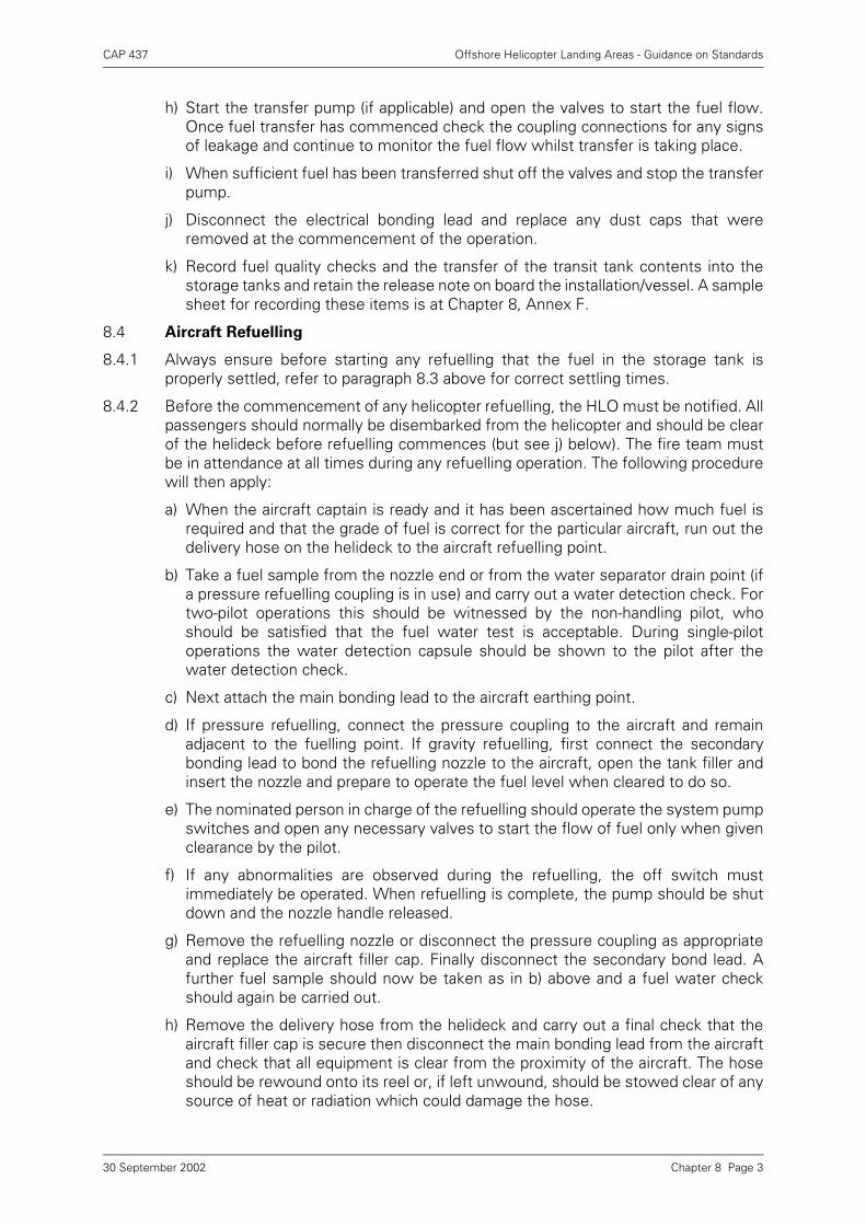
CAP 437 Offshore Helicopter Landing Areas - Guidance on Standards
h) Start the transfer pump (if applicable) and open the valves to start the fuel flow.Once fuel transfer has commenced check the coupling connections for any signsof leakage and continue to monitor the fuel flow whilst transfer is taking place.
i) When sufficient fuel has been transferred shut off the valves and stop the transferpump.
j) Disconnect the electrical bonding lead and replace any dust caps that wereremoved at the commencement of the operation.
k) Record fuel quality checks and the transfer of the transit tank contents into thestorage tanks and retain the release note on board the installation/vessel. A samplesheet for recording these items is at Chapter 8, Annex F.
8.4 Aircraft Refuelling
8.4.1 Always ensure before starting any refuelling that the fuel in the storage tank isproperly settled, refer to paragraph 8.3 above for correct settling times.
8.4.2 Before the commencement of any helicopter refuelling, the HLO must be notified. Allpassengers should normally be disembarked from the helicopter and should be clearof the helideck before refuelling commences (but see j) below). The fire team mustbe in attendance at all times during any refuelling operation. The following procedurewill then apply:
a) When the aircraft captain is ready and it has been ascertained how much fuel isrequired and that the grade of fuel is correct for the particular aircraft, run out thedelivery hose on the helideck to the aircraft refuelling point.
b) Take a fuel sample from the nozzle end or from the water separator drain point (ifa pressure refuelling coupling is in use) and carry out a water detection check. Fortwo-pilot operations this should be witnessed by the non-handling pilot, whoshould be satisfied that the fuel water test is acceptable. During single-pilotoperations the water detection capsule should be shown to the pilot after thewater detection check.
c) Next attach the main bonding lead to the aircraft earthing point.
d) If pressure refuelling, connect the pressure coupling to the aircraft and remainadjacent to the fuelling point. If gravity refuelling, first connect the secondarybonding lead to bond the refuelling nozzle to the aircraft, open the tank filler andinsert the nozzle and prepare to operate the fuel level when cleared to do so.
e) The nominated person in charge of the refuelling should operate the system pumpswitches and open any necessary valves to start the flow of fuel only when givenclearance by the pilot.
f) If any abnormalities are observed during the refuelling, the off switch mustimmediately be operated. When refuelling is complete, the pump should be shutdown and the nozzle handle released.
g) Remove the refuelling nozzle or disconnect the pressure coupling as appropriateand replace the aircraft filler cap. Finally disconnect the secondary bond lead. Afurther fuel sample should now be taken as in b) above and a fuel water checkshould again be carried out.
h) Remove the delivery hose from the helideck and carry out a final check that theaircraft filler cap is secure then disconnect the main bonding lead from the aircraftand check that all equipment is clear from the proximity of the aircraft. The hoseshould be rewound onto its reel or, if left unwound, should be stowed clear of anysource of heat or radiation which could damage the hose.
Chapter 8 Page 330 September 2002
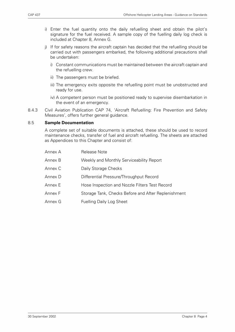
CAP 437 Offshore Helicopter Landing Areas - Guidance on Standards
i) Enter the fuel quantity onto the daily refuelling sheet and obtain the pilot’ssignature for the fuel received. A sample copy of the fuelling daily log check isincluded at Chapter 8, Annex G.
j) If for safety reasons the aircraft captain has decided that the refuelling should becarried out with passengers embarked, the following additional precautions shallbe undertaken:
i) Constant communications must be maintained between the aircraft captain andthe refuelling crew.
ii) The passengers must be briefed.
iii) The emergency exits opposite the refuelling point must be unobstructed andready for use.
iv) A competent person must be positioned ready to supervise disembarkation inthe event of an emergency.
8.4.3 Civil Aviation Publication CAP 74, ‘Aircraft Refuelling: Fire Prevention and SafetyMeasures’, offers further general guidance.
8.5 Sample Documentation
A complete set of suitable documents is attached, these should be used to recordmaintenance checks, transfer of fuel and aircraft refuelling. The sheets are attachedas Appendices to this Chapter and consist of:
Annex A Release Note
Annex B Weekly and Monthly Serviceability Report
Annex C Daily Storage Checks
Annex D Differential Pressure/Throughput Record
Annex E Hose Inspection and Nozzle Filters Test Record
Annex F Storage Tank, Checks Before and After Replenishment
Annex G Fuelling Daily Log Sheet
Chapter 8 Page 430 September 2002
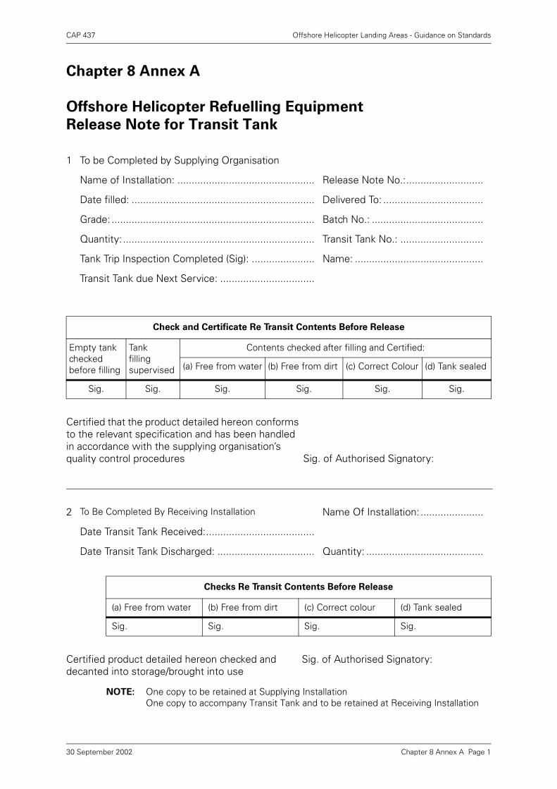
CAP 437 Offshore Helicopter Landing Areas - Guidance on Standards
Chapter 8 Annex A Page 1
Chapter 8 Annex A
Offshore Helicopter Refuelling Equipment
Release Note for Transit Tank
NOTE: One copy to be retained at Supplying InstallationOne copy to accompany Transit Tank and to be retained at Receiving Installation
1 To be Completed by Supplying Organisation
Name of Installation: ................................................ Release Note No.:...........................
Date filled: ................................................................ Delivered To: ...................................
Grade: ....................................................................... Batch No.: .......................................
Quantity: ................................................................... Transit Tank No.: .............................
Tank Trip Inspection Completed (Sig): ...................... Name: .............................................
Transit Tank due Next Service: .................................
Check and Certificate Re Transit Contents Before Release
Empty tank checked before filling
Tankfillingsupervised
Contents checked after filling and Certified:
(a) Free from water (b) Free from dirt (c) Correct Colour (d) Tank sealed
Sig. Sig. Sig. Sig. Sig. Sig.
Certified that the product detailed hereon conforms to the relevant specification and has been handled in accordance with the supplying organisation’s quality control procedures Sig. of Authorised Signatory:
2 To Be Completed By Receiving Installation Name Of Installation: ......................
Date Transit Tank Received:......................................
Date Transit Tank Discharged: .................................. Quantity: .........................................
Checks Re Transit Contents Before Release
(a) Free from water (b) Free from dirt (c) Correct colour (d) Tank sealed
Sig. Sig. Sig. Sig.
Certified product detailed hereon checked and decanted into storage/brought into use
Sig. of Authorised Signatory:
30 September 2002
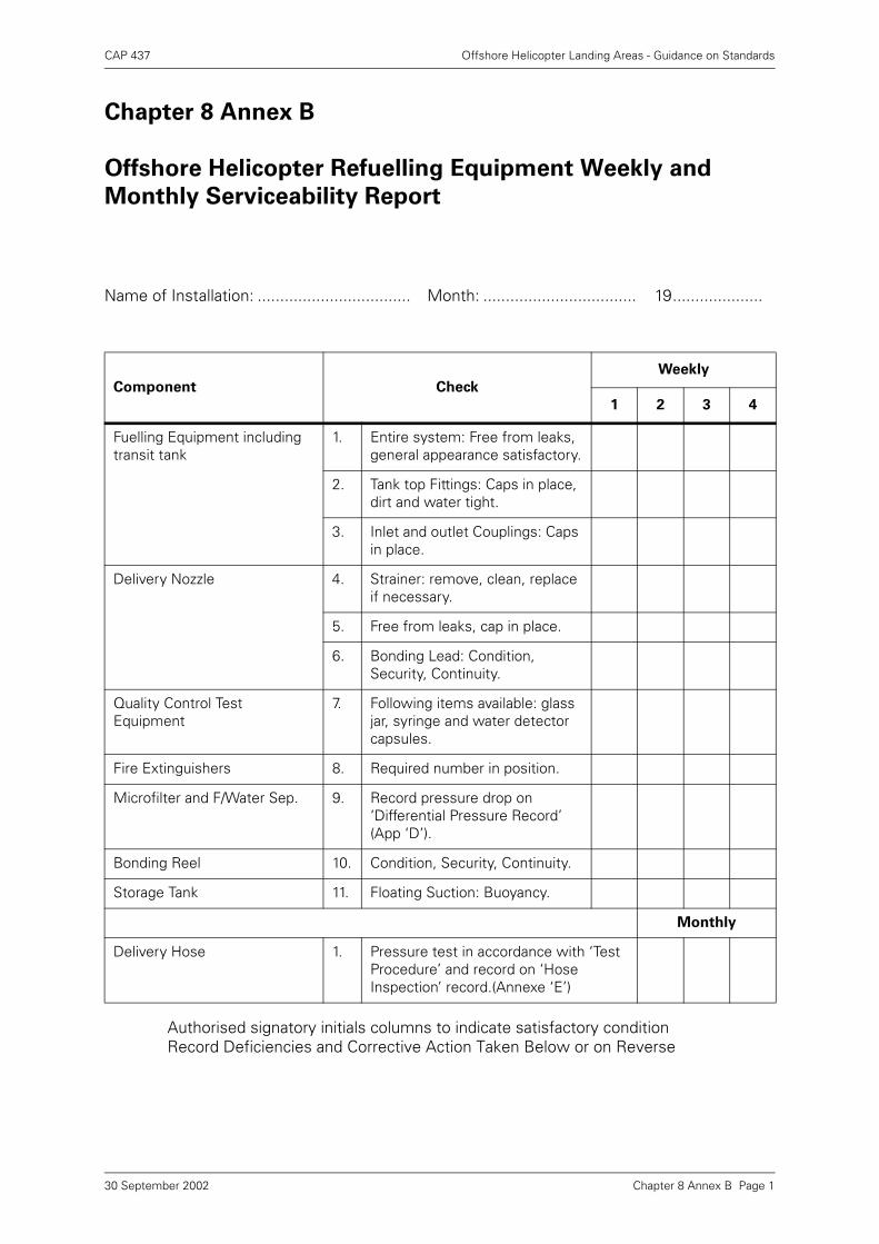
CAP 437 Offshore Helicopter Landing Areas - Guidance on Standards
Chapter 8 Annex B Page 1
Chapter 8 Annex B
Offshore Helicopter Refuelling Equipment Weekly and
Monthly Serviceability Report
Authorised signatory initials columns to indicate satisfactory conditionRecord Deficiencies and Corrective Action Taken Below or on Reverse
Name of Installation: .................................. Month: .................................. 19....................
Component Check
Weekly
1 2 3 4
Fuelling Equipment including transit tank
1. Entire system: Free from leaks, general appearance satisfactory.
2. Tank top Fittings: Caps in place, dirt and water tight.
3. Inlet and outlet Couplings: Caps in place.
Delivery Nozzle 4. Strainer: remove, clean, replace if necessary.
5. Free from leaks, cap in place.
6. Bonding Lead: Condition, Security, Continuity.
Quality Control Test Equipment
7. Following items available: glass jar, syringe and water detector capsules.
Fire Extinguishers 8. Required number in position.
Microfilter and F/Water Sep. 9. Record pressure drop on ‘Differential Pressure Record’ (App ‘D’).
Bonding Reel 10. Condition, Security, Continuity.
Storage Tank 11. Floating Suction: Buoyancy.
Monthly
Delivery Hose 1. Pressure test in accordance with ‘Test Procedure’ and record on ‘Hose Inspection’ record.(Annexe ‘E’)
30 September 2002
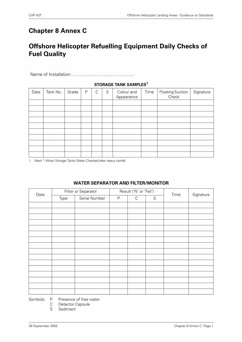
CAP 437 Offshore Helicopter Landing Areas - Guidance on Standards
Chapter 8 Annex C Page 1
Chapter 8 Annex C
Offshore Helicopter Refuelling Equipment Daily Checks of
Fuel Quality
Name of Installation: .................................................
STORAGE TANK SAMPLES1
1. Mark * When Storage Tanks Water Checked after heavy rainfall
Date Tank No. Grade P C S Colour and Appearance
Time Floating Suction Check
Signature
WATER SEPARATOR AND FILTER/MONITOR
DateFilter or Separator Result (‘N’ or ‘Fail’)
Time SignatureType Serial Number P C S
Symbols: P C S
Presence of free waterDetector CapsuleSediment
30 September 2002
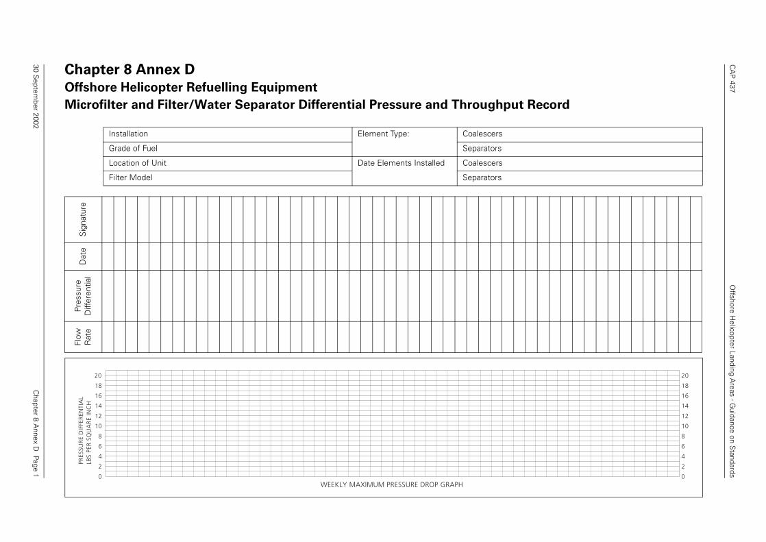
CA
P 437
Offshore H
elicopter Landing Areas - G
uidance on Standards
Chapter 8 A
nnex D P
age 1
Chapter 8 Annex D
Offshore Helicopter Refuelling Equipment
Microfilter and Filter/Water Separator Differential Pressure and Throughput Record
Installation Element Type: Coalescers
Grade of Fuel Separators
Location of Unit Date Elements Installed Coalescers
Filter Model Separators
Sig
natu
reD
ate
Pres
sure
D
iffer
entia
lFl
ow
Rat
ePR
ESSU
RE
DIF
FER
ENTI
AL
LBS
PER
SQ
UA
RE
INC
H
20
18
16
14
12
10
8
6
4
2
0
20
18
16
14
12
10
8
6
4
2
0WEEKLY MAXIMUM PRESSURE DROP GRAPH
30 Septem
ber 2002
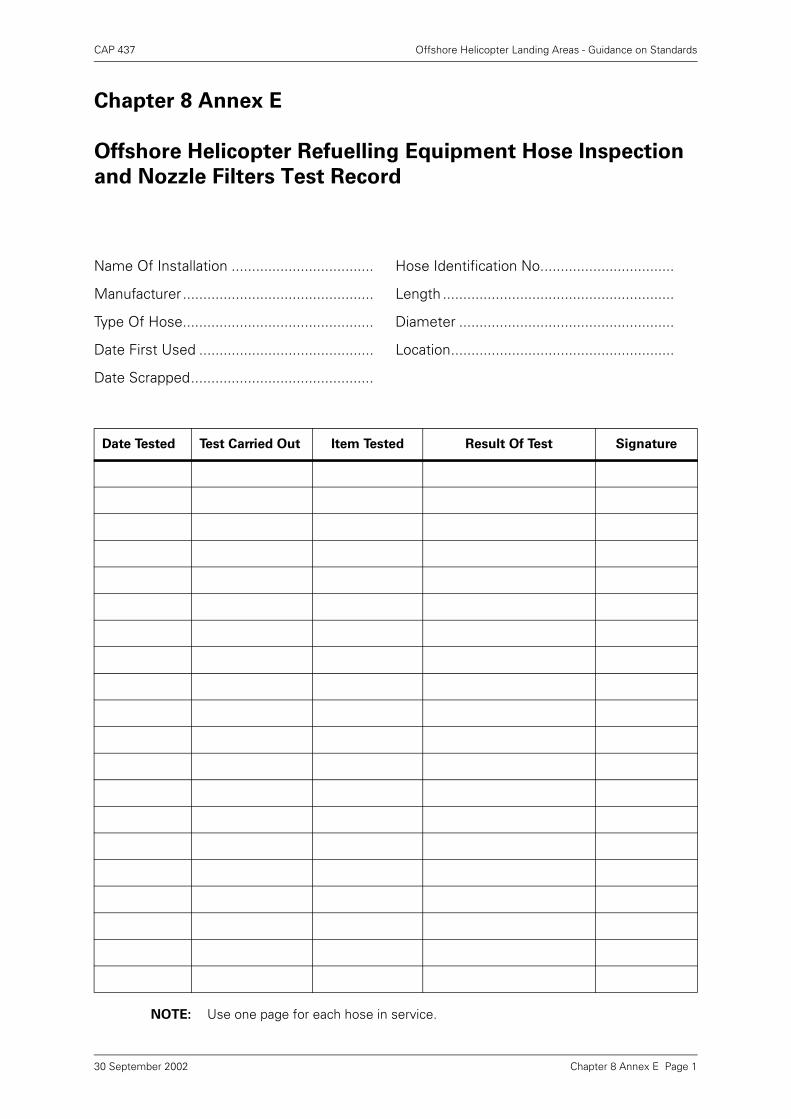
CAP 437 Offshore Helicopter Landing Areas - Guidance on Standards
Chapter 8 Annex E Page 1
Chapter 8 Annex E
Offshore Helicopter Refuelling Equipment Hose Inspection
and Nozzle Filters Test Record
NOTE: Use one page for each hose in service.
Name Of Installation ................................... Hose Identification No.................................
Manufacturer ............................................... Length .........................................................
Type Of Hose............................................... Diameter .....................................................
Date First Used ........................................... Location.......................................................
Date Scrapped.............................................
Date Tested Test Carried Out Item Tested Result Of Test Signature
30 September 2002
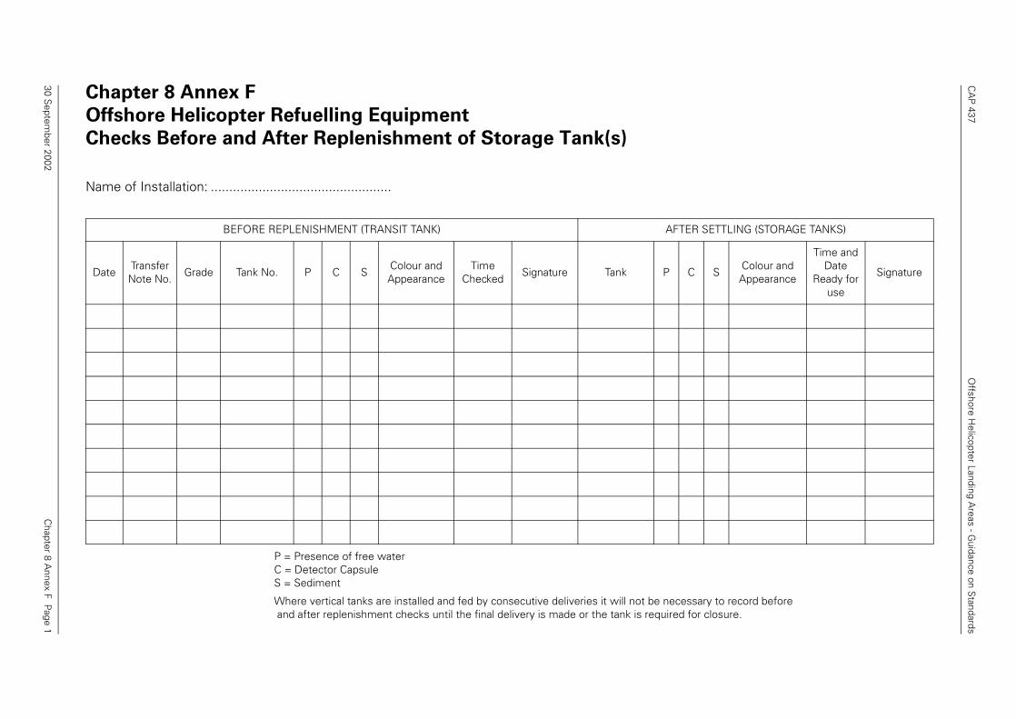
CA
P 437
Offshore H
elicopter Landing Areas - G
uidance on Standards
Chapter 8 A
nnex F Page 1
Chapter 8 Annex F
Offshore Helicopter Refuelling Equipment
Checks Before and After Replenishment of Storage Tank(s)
P = Presence of free waterC = Detector CapsuleS = Sediment
Where vertical tanks are installed and fed by consecutive deliveries it will not be necessary to record before and after replenishment checks until the final delivery is made or the tank is required for closure.
Name of Installation: .................................................
BEFORE REPLENISHMENT (TRANSIT TANK) AFTER SETTLING (STORAGE TANKS)
DateTransfer Note No.
Grade Tank No. P C SColour and Appearance
Time Checked
Signature Tank P C SColour and Appearance
Time and Date
Ready for use
Signature
30 Septem
ber 2002
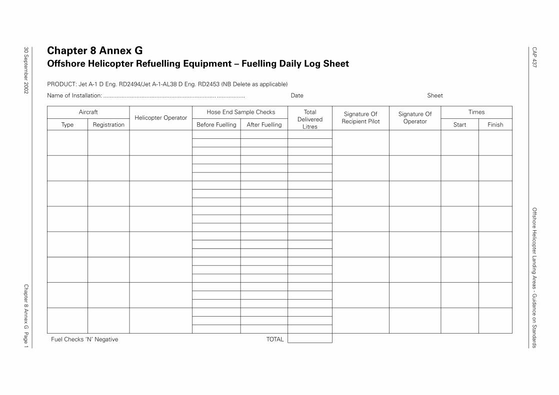
CA
P 437
Offshore H
elicopter Landing Areas - G
uidance on Standards
Chapter 8 A
nnex G P
age 1
Chapter 8 Annex G
Offshore Helicopter Refuelling Equipment – Fuelling Daily Log Sheet
PRODUCT: Jet A-1 D Eng. RD2494/Jet A-1-AL38 D Eng. RD2453 (NB Delete as applicable)
Name of Installation: .................................................................... ................. Date Sheet
AircraftHelicopter Operator
Hose End Sample Checks Total Delivered
Litres
Signature Of Recipient Pilot
Signature Of Operator
Times
Type Registration Before Fuelling After Fuelling Start Finish
Fuel Checks ‘N’ Negative TOTAL
30 Septem
ber 2002
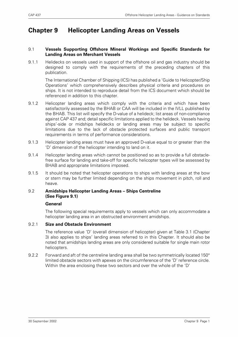
CAP 437 Offshore Helicopter Landing Areas - Guidance on Standards
Chapter 9 Helicopter Landing Areas on Vessels
9.1 Vessels Supporting Offshore Mineral Workings and Specific Standards for
Landing Areas on Merchant Vessels
9.1.1 Helidecks on vessels used in support of the offshore oil and gas industry should bedesigned to comply with the requirements of the preceding chapters of thispublication.
The International Chamber of Shipping (ICS) has published a ‘Guide to Helicopter/ShipOperations’ which comprehensively describes physical criteria and procedures onships. It is not intended to reproduce detail from the ICS document which should bereferenced in addition to this chapter.
9.1.2 Helicopter landing areas which comply with the criteria and which have beensatisfactorily assessed by the BHAB or CAA will be included in the IVLL published bythe BHAB. This list will specify the D-value of a helideck; list areas of non-complianceagainst CAP 437 and; detail specific limitations applied to the helideck. Vessels havingships’-side or midships helidecks or landing areas may be subject to specificlimitations due to the lack of obstacle protected surfaces and public transportrequirements in terms of performance considerations.
9.1.3 Helicopter landing areas must have an approved D-value equal to or greater than the‘D’ dimension of the helicopter intending to land on it.
9.1.4 Helicopter landing areas which cannot be positioned so as to provide a full obstacle-free surface for landing and take-off for specific helicopter types will be assessed byBHAB and appropriate limitations imposed.
9.1.5 It should be noted that helicopter operations to ships with landing areas at the bowor stern may be further limited depending on the ships movement in pitch, roll andheave.
9.2 Amidships Helicopter Landing Areas – Ships Centreline
(See Figure 9.1)
General
The following special requirements apply to vessels which can only accommodate ahelicopter landing area in an obstructed environment amidships.
9.2.1 Size and Obstacle Environment
The reference value ‘D’ (overall dimension of helicopter) given at Table 3.1 (Chapter3) also applies to ships’ landing areas referred to in this Chapter. It should also benoted that amidships landing areas are only considered suitable for single main rotorhelicopters.
9.2.2 Forward and aft of the centreline landing area shall be two symmetrically located 150°limited obstacle sectors with apexes on the circumference of the ‘D’ reference circle.Within the area enclosing these two sectors and over the whole of the ‘D’
Chapter 9 Page 130 September 2002
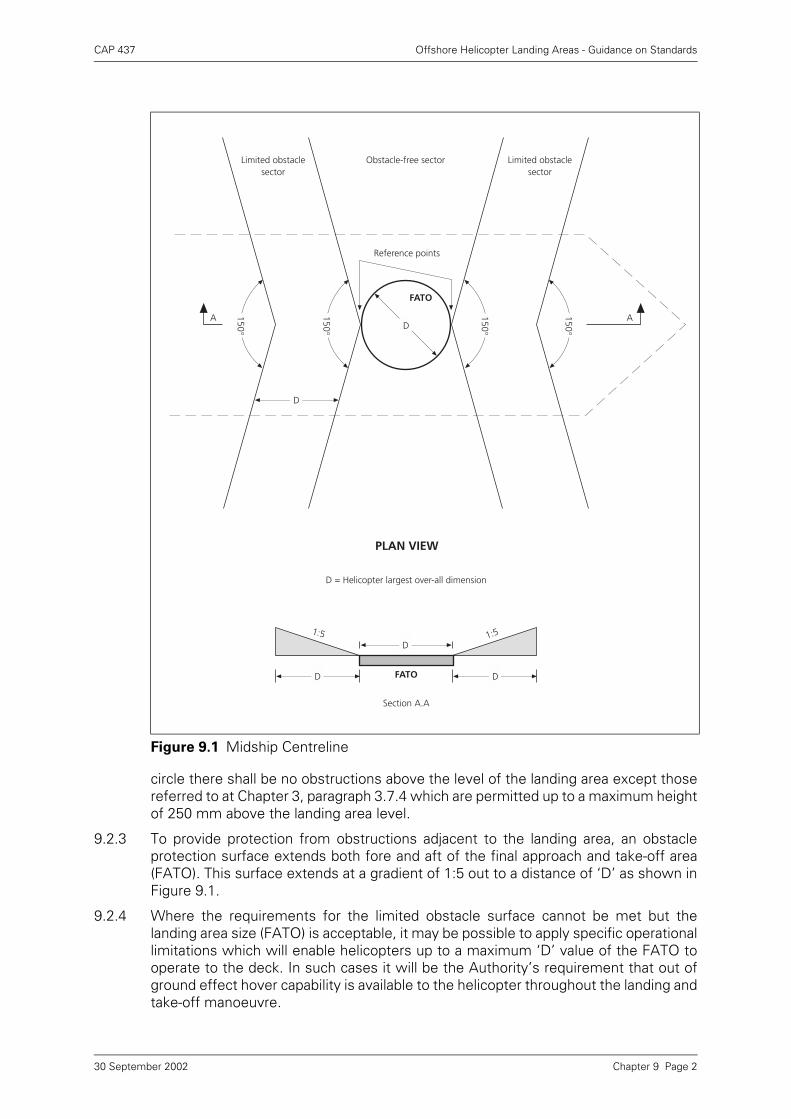
CAP 437 Offshore Helicopter Landing Areas - Guidance on Standards
circle there shall be no obstructions above the level of the landing area except thosereferred to at Chapter 3, paragraph 3.7.4 which are permitted up to a maximum heightof 250 mm above the landing area level.
9.2.3 To provide protection from obstructions adjacent to the landing area, an obstacleprotection surface extends both fore and aft of the final approach and take-off area(FATO). This surface extends at a gradient of 1:5 out to a distance of ‘D’ as shown inFigure 9.1.
9.2.4 Where the requirements for the limited obstacle surface cannot be met but thelanding area size (FATO) is acceptable, it may be possible to apply specific operationallimitations which will enable helicopters up to a maximum ‘D’ value of the FATO tooperate to the deck. In such cases it will be the Authority’s requirement that out ofground effect hover capability is available to the helicopter throughout the landing andtake-off manoeuvre.
Figure 9.1 Midship Centreline
Limited obstaclesector
Obstacle-free sector Limited obstaclesector
150°
150°
150°
150°
Reference points
FATO
D
D
A A
PLAN VIEW
D = Helicopter largest over-all dimension
1:5 1:5D
FATOD D
Section A.A
Chapter 9 Page 230 September 2002
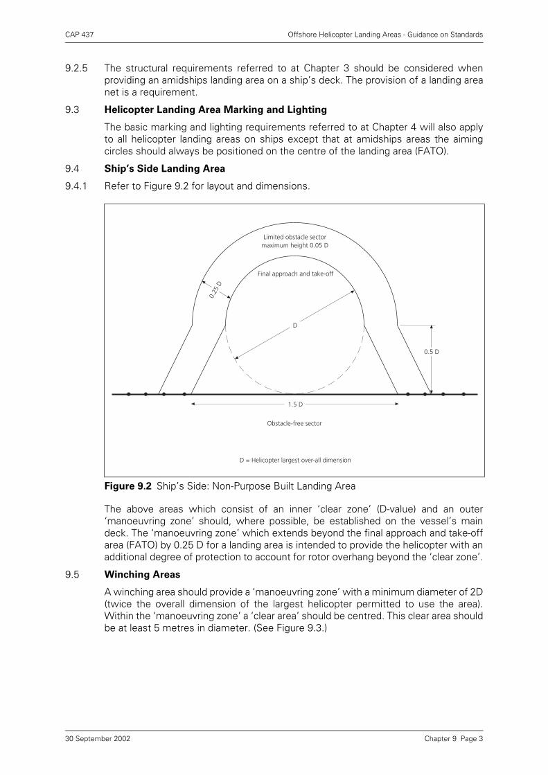
CAP 437 Offshore Helicopter Landing Areas - Guidance on Standards
9.2.5 The structural requirements referred to at Chapter 3 should be considered whenproviding an amidships landing area on a ship’s deck. The provision of a landing areanet is a requirement.
9.3 Helicopter Landing Area Marking and Lighting
The basic marking and lighting requirements referred to at Chapter 4 will also applyto all helicopter landing areas on ships except that at amidships areas the aimingcircles should always be positioned on the centre of the landing area (FATO).
9.4 Ship’s Side Landing Area
9.4.1 Refer to Figure 9.2 for layout and dimensions.
The above areas which consist of an inner ‘clear zone’ (D-value) and an outer‘manoeuvring zone’ should, where possible, be established on the vessel’s maindeck. The ‘manoeuvring zone’ which extends beyond the final approach and take-offarea (FATO) by 0.25 D for a landing area is intended to provide the helicopter with anadditional degree of protection to account for rotor overhang beyond the ‘clear zone’.
9.5 Winching Areas
A winching area should provide a ‘manoeuvring zone’ with a minimum diameter of 2D(twice the overall dimension of the largest helicopter permitted to use the area).Within the ‘manoeuvring zone’ a ‘clear area’ should be centred. This clear area shouldbe at least 5 metres in diameter. (See Figure 9.3.)
Figure 9.2 Ship’s Side: Non-Purpose Built Landing Area
Obstacle-free sector
D = Helicopter largest over-all dimension
1.5 D
Final approach and take-off
DD
0.5 D
0.25
D
Limited obstacle sectormaximum height 0.05 D
Chapter 9 Page 330 September 2002
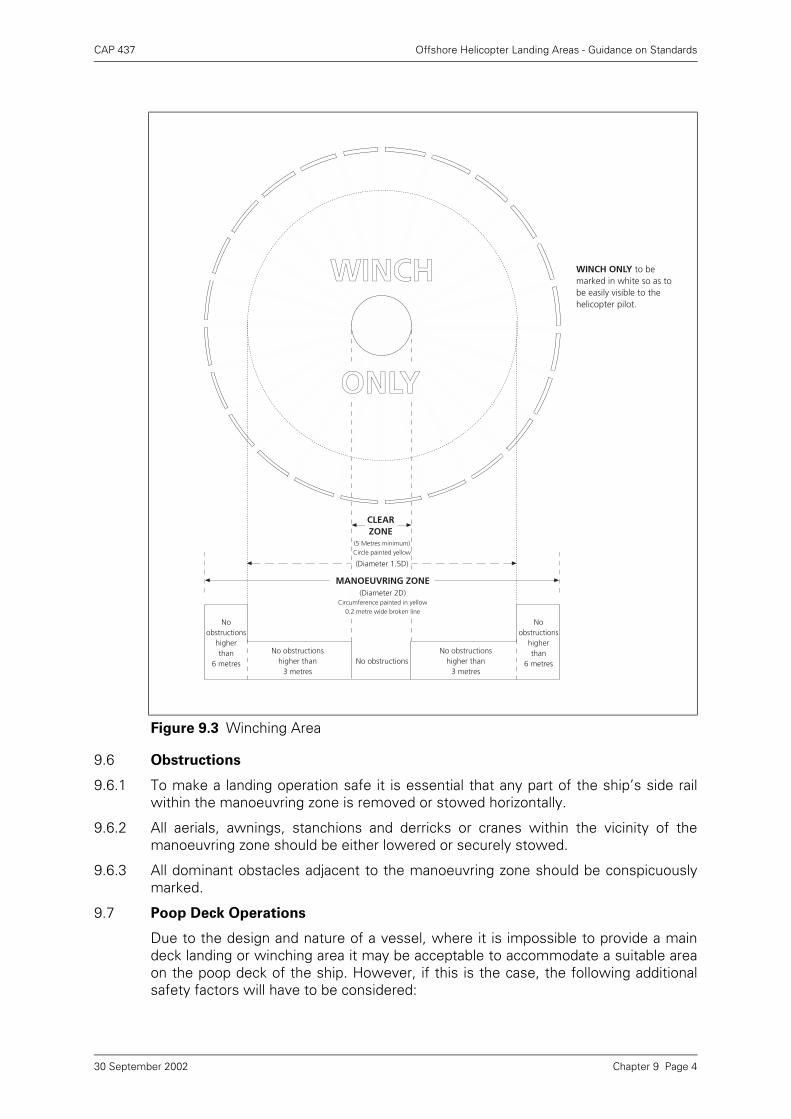
CAP 437 Offshore Helicopter Landing Areas - Guidance on Standards
9.6 Obstructions
9.6.1 To make a landing operation safe it is essential that any part of the ship’s side railwithin the manoeuvring zone is removed or stowed horizontally.
9.6.2 All aerials, awnings, stanchions and derricks or cranes within the vicinity of themanoeuvring zone should be either lowered or securely stowed.
9.6.3 All dominant obstacles adjacent to the manoeuvring zone should be conspicuouslymarked.
9.7 Poop Deck Operations
Due to the design and nature of a vessel, where it is impossible to provide a maindeck landing or winching area it may be acceptable to accommodate a suitable areaon the poop deck of the ship. However, if this is the case, the following additionalsafety factors will have to be considered:
Figure 9.3 Winching Area
WINCH ONLY to bemarked in white so as tobe easily visible to thehelicopter pilot.
WINCH
Noobstructions
higher than
6 metres
No obstructionshigher than
3 metresNo obstructions
ONLY
No obstructionshigher than
3 metres
Noobstructions
higher than
6 metres
CLEARZONE
(5 Metres minimum)Circle painted yellow
(Diameter 1.5D)
MANOEUVRING ZONE (Diameter 2D)
Circumference painted in yellow0.2 metre wide broken line
Chapter 9 Page 430 September 2002
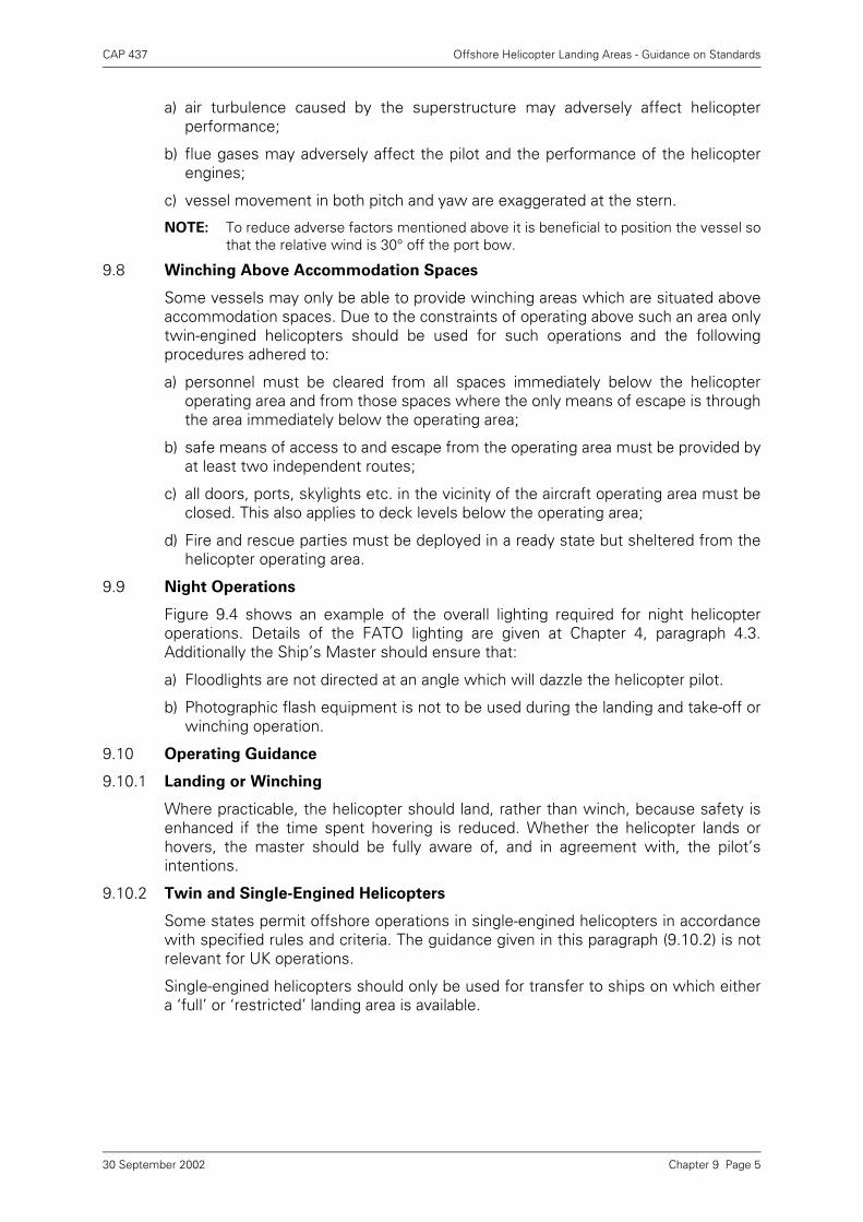
CAP 437 Offshore Helicopter Landing Areas - Guidance on Standards
a) air turbulence caused by the superstructure may adversely affect helicopterperformance;
b) flue gases may adversely affect the pilot and the performance of the helicopterengines;
c) vessel movement in both pitch and yaw are exaggerated at the stern.
NOTE: To reduce adverse factors mentioned above it is beneficial to position the vessel sothat the relative wind is 30° off the port bow.
9.8 Winching Above Accommodation Spaces
Some vessels may only be able to provide winching areas which are situated aboveaccommodation spaces. Due to the constraints of operating above such an area onlytwin-engined helicopters should be used for such operations and the followingprocedures adhered to:
a) personnel must be cleared from all spaces immediately below the helicopteroperating area and from those spaces where the only means of escape is throughthe area immediately below the operating area;
b) safe means of access to and escape from the operating area must be provided byat least two independent routes;
c) all doors, ports, skylights etc. in the vicinity of the aircraft operating area must beclosed. This also applies to deck levels below the operating area;
d) Fire and rescue parties must be deployed in a ready state but sheltered from thehelicopter operating area.
9.9 Night Operations
Figure 9.4 shows an example of the overall lighting required for night helicopteroperations. Details of the FATO lighting are given at Chapter 4, paragraph 4.3.Additionally the Ship’s Master should ensure that:
a) Floodlights are not directed at an angle which will dazzle the helicopter pilot.
b) Photographic flash equipment is not to be used during the landing and take-off orwinching operation.
9.10 Operating Guidance
9.10.1 Landing or Winching
Where practicable, the helicopter should land, rather than winch, because safety isenhanced if the time spent hovering is reduced. Whether the helicopter lands orhovers, the master should be fully aware of, and in agreement with, the pilot’sintentions.
9.10.2 Twin and Single-Engined Helicopters
Some states permit offshore operations in single-engined helicopters in accordancewith specified rules and criteria. The guidance given in this paragraph (9.10.2) is notrelevant for UK operations.
Single-engined helicopters should only be used for transfer to ships on which eithera ‘full’ or ‘restricted’ landing area is available.
Chapter 9 Page 530 September 2002
CAP 437 Offshore Helicopter Landing Areas - Guidance on Standards
At night, single-engined helicopters should only be used to transfer stores. Theyshould not be used to transfer personnel.
Personnel should normally be winched only from multi-engined helicopters with aone-engine-inoperative hover capability.
When helicopter operations are being carried out above winching areas in the vicinityof accommodation spaces, compliance with the requirements of paragraph 9.8 isespecially important.
The following Table 9.1 shows the operations which may be conducted with twin-engined and single-engined helicopters respectively, subject to local regulations.
* Winching area may be used only if a ‘full’ or ‘restricted’ landing area is not availableor cannot be used.
9.10.3 Weather Conditions
Limiting weather conditions will be in accordance with the requirements of thehelicopter operator’s ‘Operations Manual’. Some vessels may apply lower limits forpersonnel movement on the helideck.
Figure 9.4 Night Operations: Lighting Requirements
Table 9.1 Twin- and single-engined helicopter operations
Personnel Stores
Landing Winching Landing Winching
Day Night Day Night Day Night Day Night
Twin Engined YES YES YES* YES* YES YES YES YES
Single Engined YES NO NO NO YES YES NO NO
Derrick post floodlightsilluminating operating area
Floodlights illuminatingderrick posts
Marshaller with illuminated batonsstands well clear of operating area
International codepennantused for wind reference
Floodlightilluminatingwind reference
FloodlightilluminatingForemast
Floodlights illuminatingaccommodation front
Signal prescribed by Rule 27 (b)1972 Collision Regulations
Floodlightsilluminating funnel
H
Pipe line Mas
t
22
22
‘0’ Hatch
22 22
Signal prescribed by Rule 27 (b)1972 Collision Regulations
Chapter 9 Page 630 September 2002
CAP 437 Offshore Helicopter Landing Areas - Guidance on Standards
Chapter 10 Tandem Rotor Helicopter Helidecks
NOTE: For structural load considerations refer to HSE 4th Edition Guidance and Chapter 3,paragraph 3.5 above. There are currently no tandem rotor helicopters operating in UKwaters. This chapter is written to provide guidance and an explanation on helidecksmarked for tandem rotor helicopters which may appear in UK waters. Ideally suchhelidecks should be re-marked for single rotor helicopters in accordance withChapters 3 and 4 above. The criteria listed below is taken from the last edition ofCAP 437 and is intended for use only where appropriate.
10.1 To allow for omnidirectional landings for any helicopter having tandem main rotors,the area should be sufficiently large to contain a D circle of diameter 0.9 D, where Dis the measurement across the rotors in a fore and aft line. If this cannot be met, alanding area rectangle should be provided with a major axis of at least 0.9 D and aminor axis of at least 0.75 D. To allow for omnidirectional landings for any helicopterhaving tandem main rotors, the area should be sufficiently large to contain a landingarea circle of diameter 0.9 D, where D is the measurement across the rotors in a foreand aft line. If this cannot be met, a landing area rectangle should be provided with amajor axis of at least 0.9 D and a minor axis of at least 0.75 D, which dimension willallow for bi-directional landings only.
10.1.1 Within this landing rectangle, bi-directional landings will be permitted in the directionof the major axis only. (If necessary for design purposes, any of the corners of thisrectangle may be omitted provided that neither of the two sides forming the rightangle of any such triangle exceeds 0.18 D in length). (This is illustrated in Figure 10.1.)
10.1.2 From any point on the periphery of the above-mentioned landing area circles, or fromthe inboard end of the minor axis of the landing area rectangle, an obstacle-freeapproach and take-off sector should be provided which totally encloses the landingarea circle or rectangle and which extends over an arc of at least 210°. Within thissector, and out to a distance of 1000 metres from the periphery of the landing area,only the following items may exceed the height of the landing area, but should not doso by more than 0.25 metres:
• the guttering or slightly raised kerb (associated with the requirements in Chapter3);
• the lighting required by Chapter 4;
• the outboard edge of the safety net required in Chapter 3;
• the foam monitors;
• those handrails and other items associated with the landing area which areincapable of complete retraction or lowering for helicopter operations.
NOTE: As a general rule, at helidecks where obstacle free sectors are infringed byinstallations or vessels which are positioned within 1000 metres of the point of originof the sector, it may be necessary to impose helicopter operating restrictions. (SeeChapter 6 for further details.)
Chapter 10 Page 130 September 2002
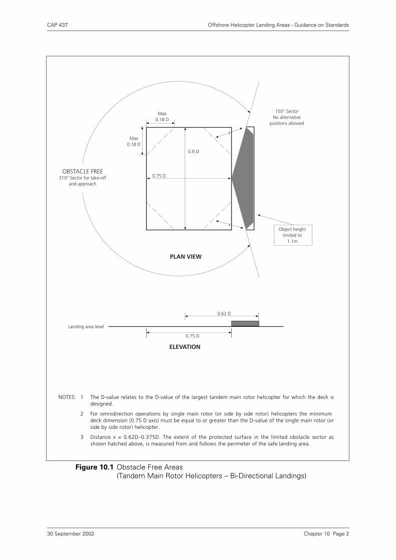
CAP 437 Offshore Helicopter Landing Areas - Guidance on Standards
Figure 10.1 Obstacle Free Areas(Tandem Main Rotor Helicopters – Bi-Directional Landings)
PLAN VIEW
OBSTACLE FREE210° Sector for take-off
and approach
150° SectorNo alternative
positions allowed
Object heightlimited to
1.1m
0.75 D
0.62 D
0.75 D
ELEVATION
Landing area level
0.9 D
Max0.18 D
Max0.18 D
x
x
NOTES: 1 The D-value relates to the D-value of the largest tandem main rotor helicopter for which the deck isdesigned.
2 For omnidirection operations by single main rotor (or side by side rotor) helicopters the minimumdeck dimension (0.75 D axis) must be equal to or greater than the D-value of the single main rotor (orside by side rotor) helicopter.
3 Distance x = 0.62D–0.375D. The extent of the protected surface in the limited obstacle sector asshown hatched above, is measured from and follows the perimeter of the safe landing area.
Chapter 10 Page 230 September 2002
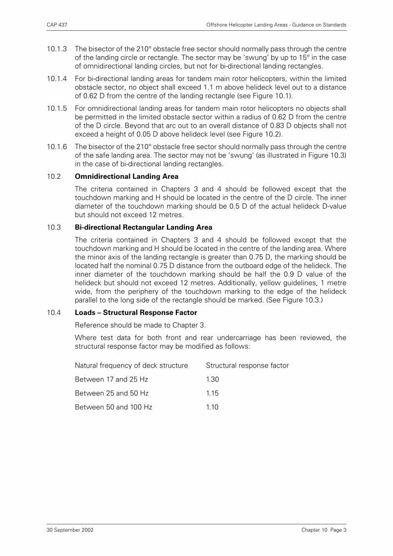
CAP 437 Offshore Helicopter Landing Areas - Guidance on Standards
10.1.3 The bisector of the 210° obstacle free sector should normally pass through the centreof the landing circle or rectangle. The sector may be ‘swung’ by up to 15° in the caseof omnidirectional landing circles, but not for bi-directional landing rectangles.
10.1.4 For bi-directional landing areas for tandem main rotor helicopters, within the limitedobstacle sector, no object shall exceed 1.1 m above helideck level out to a distanceof 0.62 D from the centre of the landing rectangle (see Figure 10.1).
10.1.5 For omnidirectional landing areas for tandem main rotor helicopters no objects shallbe permitted in the limited obstacle sector within a radius of 0.62 D from the centreof the D circle. Beyond that arc out to an overall distance of 0.83 D objects shall notexceed a height of 0.05 D above helideck level (see Figure 10.2).
10.1.6 The bisector of the 210° obstacle free sector should normally pass through the centreof the safe landing area. The sector may not be ‘swung’ (as illustrated in Figure 10.3)in the case of bi-directional landing rectangles.
10.2 Omnidirectional Landing Area
The criteria contained in Chapters 3 and 4 should be followed except that thetouchdown marking and H should be located in the centre of the D circle. The innerdiameter of the touchdown marking should be 0.5 D of the actual helideck D-valuebut should not exceed 12 metres.
10.3 Bi-directional Rectangular Landing Area
The criteria contained in Chapters 3 and 4 should be followed except that thetouchdown marking and H should be located in the centre of the landing area. Wherethe minor axis of the landing rectangle is greater than 0.75 D, the marking should belocated half the nominal 0.75 D distance from the outboard edge of the helideck. Theinner diameter of the touchdown marking should be half the 0.9 D value of thehelideck but should not exceed 12 metres. Additionally, yellow guidelines, 1 metrewide, from the periphery of the touchdown marking to the edge of the helideckparallel to the long side of the rectangle should be marked. (See Figure 10.3.)
10.4 Loads – Structural Response Factor
Reference should be made to Chapter 3.
Where test data for both front and rear undercarriage has been reviewed, thestructural response factor may be modified as follows:
Natural frequency of deck structure Structural response factor
Between 17 and 25 Hz 1.30
Between 25 and 50 Hz 1.15
Between 50 and 100 Hz 1.10
Chapter 10 Page 330 September 2002
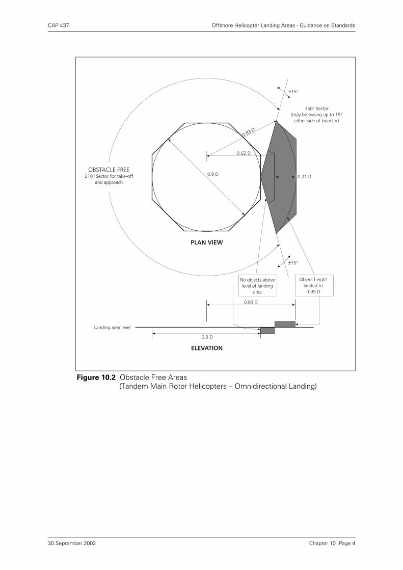
CAP 437 Offshore Helicopter Landing Areas - Guidance on Standards
Figure 10.2 Obstacle Free Areas (Tandem Main Rotor Helicopters – Omnidirectional Landing)
PLAN VIEW
OBSTACLE FREE210° Sector for take-off
and approach
150° Sector(may be swung up to 15°
either side of bisector)
Object heightlimited to
0.05 D
0.62 D
0.9 D
0.83 D
±15°
±15°
No objects abovelevel of landing
area
0.83 D
0.21 D
PLAN VIEW
OBSTACLE FREE210° Sector for take-off
and approach
150° Sector(may be swung up to 15°
either side of bisector)
Object heightlimited to
0.05 D
0.62 D
0.9 D
0.83 D
0.9 D
ELEVATION
±15°
±15°
Landing area level
No objects abovelevel of landing
area
0.83 D
0.21 D
Chapter 10 Page 430 September 2002
CAP 437 Offshore Helicopter Landing Areas - Guidance on Standards
Figure 10.3 Bi-Directional Markings for Tandem Main Rotor Helicopter Operations
NOTES: 1 The D-value relates to the D-value of the largest tandem main rotor helicopterfor which the helideck is designed.
2 For omnidirectional operations by single main rotor (or side by side rotor)helicopters the minimum deck dimension (0.75 D axis) must be equal to orgreater than the D-value of the largest single rotor (or side by side rotor)helicopter approved to use the deck.
3 Where the minor axis is greater than the minimum 0.75 D, the ‘H’ should belocated ½ of the nominal 0.75 D from the outboard edge of the deck.
Centre ofLanding
Rectangle
0.75 DMin
INSTA
LLATIO
N N
AM
E
1.2M
0.18 DMAX
0.18 DMAX
0.9 D
1M
150° SectorNo alternative
position allowed
No objectabove 1.1M
0.62 D
150° Sector(No alternative
position allowed)
Chapter 10 Page 530 September 2002
CAP 437 Offshore Helicopter Landing Areas - Guidance on Standards
Appendix A Checklist
The following checklist indicates in general terms the minimum number of helideckphysical characteristics which the Civil Aviation Authority considers should beexamined during periodic surveys to confirm that there has been no alteration ordeterioration in condition.
a) Helideck Dimensions:
i) D-value as measured;
ii) Declared D-value;
iii) Deck shape;
iv) Scale drawings of deck arrangement.
b) Deck Landing Area Conditions:
i) Type of surface, condition, friction, contaminant free;
ii) Fuel retention;
iii) Deck landing area net;
iv) Perimeter safety netting;
v) Tie-down points.
c) Environment:
i) Turbine and other exhausts;
ii) Hot and cold gas emissions;
iii) Turbulence generators;
iv) Flares;
v) Emergency gas release systems;
vi) Adjacent fixed/mobile/vessel exhausts, gas emissions, flares, and turbulencegenerators.
d) Obstacle Protected Surfaces (Minima):
i) Obstacle free sector (210°);
ii) Limited obstacle sector (150°);
iii) Falling 5:1 gradient;
iv) Note if i) or iii) above are swung from normal axis.
e) Visual Aids:
i) Deck surface;
ii) General condition of painted markings;
iii) Location of H;
iv) Aiming circle;
v) Safe Landing Area perimeter line – relationship to Chevron;
vi) D-value marked within perimeter line;
Appendix A Page 130 September 2002
CAP 437 Offshore Helicopter Landing Areas - Guidance on Standards
vii)Chevron marking (if reduced the sector is to be marked in degrees);
viii)Certification marking (exact D-value);
ix) Maximum allowable weight marking;
x) Conspicuity of installation name;
xi) Wind indicator;
xii)Perimeter lighting;
xiii)Floodlighting;
xiv)Obstruction lighting;
xv)Marking of dominant obstacles;
xvi)Shield of installation working lights (helideck light pollution).
f) Fuel System:
i) Jet A-1 installation;
ii) Hose;
iii) Earthing equipment.
Appendix A Page 230 September 2002

CAP 437 Offshore Helicopter Landing Areas - Guidance on Standards
Appendix B Bibliography
References in Chapter 3
Other References
Guide to Helicopter/Ship Operations, International Chamber of Shipping, ThirdEdition, May 1989.
Offshore Installations: Guidance on Design, Construction and Certification, Healthand Safety Executive, HMSO ISBN 0 11 4106126.
International Civil Aviation Organization
UK Offshore Operators Association (UKOOA)
UKOOA publish a very composite range of guidance documents on all aspects ofoffshore operations. Only the two publications referenced in CAP 437 are shownabove. For a full listing of UKOOA guidlines and documents refer to ‘Sources’ below.
1 M E Davies, L R Cole and P G O’Neill. The Nature of Air Flows over Offshore Platforms, NMI Report R14 dated June 1977.
M E Davies, L R Cole and P G O’Neill. Wind Tunnel Investigation of the Temperature Field due to the Hot Exhaust of Power Generation Plants on Offshore Installations, NMI Report R54 dated December 1979.
M E Davies. Wind Tunnel Modelling of the Local Atmospheric Environment of Offshore Platforms. NMI Report R5 dated May 1979.
2 J M Biggs, Introduction to Structural Dynamics, McGraw Hill.
3 R J Mainstone, Structural Tests of an Experimental Helicopter Platform, Building Research Station, Engineering Series 26.
4 R J Steffans, Structural Vibration and Damage, Building Research Establishment Report 1974, HMSO.
5 R J Mainstone, Properties of Materials at High Rates of Straining or Loading, Building Research Station, CP 62/75.
ICAO Doc 9261 AN/903 Heliport Manual
ICAO Doc 9284 AN/905 Technical Instruction for the Safe Transport of Dangerous Goods by Air
ICAO Annex 14 Volume II Heliports
UKOOA Guidance documents on Management of Offshore Helideck Operations on NAIs & NUIs
UKOOA Guidelines for Helicopter Refuelling Systems
Appendix B Page 130 September 2002
CAP 437 Offshore Helicopter Landing Areas - Guidance on Standards
Offshore Petroleum Industry Training Organisation (OPITO)
Helicopter Landing Officers Handbook (OPITO)
Helicopter Refuelling Handbook (OPITO)
Civil Aviation Authority
Sources
Civil Aviation Publications (CAPs) and Civil Aviation Authority Papers (CAA Papers) arepublished on the CAA web site at www.caa.co.uk and are available in paper formatfrom Documedia Solutions Ltd, 37 Windsor Street, Cheltenham, Glos, GL52 2DG.Telephone (01242) 283131
ICAO publications are available from Airplan Flight Equipment, 1a Ringway TradingEstate, Shadowmoss Road, Manchester M22 5LH. Telephone 0161 499 0023. TheICAO website address is www.icao.int.
British Standards (BS) may be obtained from Her Majesty’s Stationery Office, PO Box276, Nine Elms Lane, London SW8 5DT. Telephone 020 7211 5656 or from anyHMSO. Advice on relevant codes (BS EN & PREN) is available from the CAA at SRGGatwick.
HSE Publications from HSE Books, PO Box 1999, Sudbury, Suffolk, CO10 6FS.Telephone (01787) 881165.
OPITO Publications from OPITO, Inchbraoch house, South Quay, Ferryden,Montrose, Scotland, DD10 9SL. Telephone (01674) 662500.
UKOOA Publications from UKOOA, 3 Hans Crescent, London, SW1X 0LN. Telephone020 7589 5255; or, from UKOOA, 9 Albyn Terrace, Aberdeen, AB10 1YP. UKOOApublications can also be viewed on the Internet at:- http\\www.ukooa.co.uk.
CAP 74 Aircraft Refuelling: Fire Prevention and Safety Measures
CAP 434 Aviation Fuel at Aerodromes
CAA Paper 98002 Friction Characteristics of Helidecks on Offshore Fixed-Manned Installations.
CAA Paper 98003 Helideck Status Signalling System
Appendix B Page 230 September 2002