CANopen - Servotronixservotronix.com/html/Help_CDHD_EN/HTML/Documents/CDHD_CANo… · Document...
403
CANopen for CAN and EtherCAT Drives Reference Manual CDHD Servo Drive Revision: 5.2 Firmware Version: 1.15.24
Transcript of CANopen - Servotronixservotronix.com/html/Help_CDHD_EN/HTML/Documents/CDHD_CANo… · Document...
CANopen for CAN and EtherCAT Drives
Reference Manual CDHD Servo Drive Revision: 5.2 Firmware Version: 1.15.24

CDHD
CANopen for CAN and EtherCAT Drives Reference Manual 3
Revision History
Document Revision
Date Remarks
5.2 Mar.2015 Firmware version 1.15.24 5.1 Jan.2015 Title modified. Removed unsupported models.
5.0 Jan. 2015 Firmware version 1.15.xx
4.2 Aug. 2014 Minor fixes. Added sections 7.9, 7.10, 7.11. New and revised figures: 10-26; 2-1, 2-2, 2-3.
4.1 May 2014 Fixed chapter numbering
4.0 May 2014 Release for firmware 1.4.6. Added chapters 10, 11, 12, 13, Revised chapters 1 and 2.
3.2 Jan. 2014 PDO mapping correction
3.1 Jan. 2014 Release for firmware 1.4.5
3.0 Oct. 2013 Release for firmware 1.4.4
2.2 May 2013 Minor fixes
2.1 Jan. 2013 General release for firmware 1.3.2
2.0 Jan. 2013 Preliminary Release
1.0 Aug. 2012 Internal release
Firmware Revision
1.15.24
Copyright Notice © 2015 Servotronix Motion Control Ltd.
All rights reserved. No part of this work may be reproduced or transmitted in any form or by any means without prior written permission of Servotronix.
Disclaimer This product documentation was accurate and reliable at the time of its release. Servotronix Motion Control Ltd. reserves the right to change the specifications of the product described in this manual without notice at any time.
Trademarks CANopen and CiA are registered trademarks of the CAN in Automation User's Group
EtherCAT is a registered trademark and patented technology, licensed by Beckhoff Automation GmbH
EnDat is a registered trademark of Dr. Johannes Heidenhain GmbH
HIPERFACE is a registered trademark of Sick Stegmann Gmbh
Windows is a registered trademark of Microsoft Corporation
CDHD
4 CANopen for CAN and EtherCAT Drives Reference Manual
Contact Information Servotronix Motion Control Ltd. 21C Yagia Kapayim Street Petach Tikva 49130, Israel Tel: +972 (3) 927 3800 Fax: +972 (3) 922 8075 Website: www.servotronix.com
Technical Support If you need assistance with the installation and configuration of the product, contact Servotronix technical support: [email protected]
CDHD
CANopen for CAN and EtherCAT Drives Reference Manual 5
Contents 1 Introduction _______________________________________________ 15
1.1 About the CAN and EtherCAT Drives ............................................................ 15 1.2 About This Manual .................................................................................... 15 1.3 Manual Format – Object Dictionary ............................................................. 16
2 Cabling and Setup ___________________________________________ 17 2.1 Hardware Configuration ............................................................................. 18
CDHD - CAN Configuration – Horner Controller – Example ............................. 18 CDHD - CAN Configuration – Beckhoff Controller – Example ........................... 19 CDHD - EtherCAT Configuration – Beckhoff Controller – Example .................... 20
2.2 Node Address ........................................................................................... 21 Node Address in CANopen Network ............................................................. 21 Node Address in EtherCAT Network ............................................................. 21
2.3 Termination Resistor Switch ....................................................................... 21 Termination Resistor Switch in CANopen Network ......................................... 21 Termination Resistor Switch in EtherCAT Network ......................................... 22
2.4 Fieldbus Communication ............................................................................ 22 Fieldbus Communication in CANopen Network .............................................. 22 Fieldbus Communication in EtherCAT Network .............................................. 22
2.5 CANopen/CoE Bit Rate ............................................................................... 23 2.6 Feedback Resolution ................................................................................. 23 2.7 Synchronization Mode ............................................................................... 24 2.8 Fieldbus Interpolation Time (Cyclic Synchronous) ......................................... 24
3 CANopen Basics ____________________________________________ 25 3.1 Device Communication .............................................................................. 25 3.2 Communication Objects ............................................................................. 26
Service Data Communication ...................................................................... 26 Process Data Communication ..................................................................... 26
3.3 Object Units ............................................................................................. 27 3.4 Object Access Types.................................................................................. 28 3.5 Errors and Faults ...................................................................................... 29
Service Request Error Codes ...................................................................... 29 Emergency Error Codes (Faults) ................................................................. 30
4 Communication Objects ______________________________________ 34 1000h – Device Type................................................................................. 34 1001h – Error Register .............................................................................. 35 1002h – Manufacturer Status Register ......................................................... 35 1003h – Predefined Error Field ................................................................... 36 1005h – COB-ID SYNC Message ................................................................. 37 1006h – Communication Cycle Period .......................................................... 37 1007h – Synchronous Window Length ......................................................... 38 1008h – Manufacturer Device Name ............................................................ 38 1009h – Manufacturer Hardware Version ..................................................... 39 100Ah – Manufacturer Software Version ...................................................... 39 100Ch – Guard Time ................................................................................. 40 100Dh – Lifetime Factor ............................................................................ 40 1010h – Store Parameter Field ................................................................... 41 1011h – Restore Default Parameters ........................................................... 43 1014h – COB-ID EMCY .............................................................................. 44 1015h – Inhibit Time Emergency ................................................................ 45 1016h – Heartbeat Consumer Time ............................................................. 46 1017h – Producer Heartbeat Time ............................................................... 47 1018h – Identity Object ............................................................................. 48
CDHD
6 CANopen for CAN and EtherCAT Drives Reference Manual
1019h – Synchronous Counter Overflow Value ............................................. 50 1029h – Error Behavior ............................................................................. 51 1200h – Server SDO Parameter 1 ............................................................... 52 1201h – Server SDO Parameter 2 ............................................................... 53 1400h – Receive PDO Communication Parameter 1 ....................................... 55 1401h – Receive PDO Communication Parameter 2 ....................................... 57 1402h – Receive PDO Communication Parameter 3 ....................................... 59 1403h – Receive PDO Communication Parameter 4 ....................................... 61 1600h – Receive PDO Mapping Parameter 1 ................................................. 63 1601h – Receive PDO Mapping Parameter 2 ................................................. 65 1602h – Receive PDO Mapping Parameter 3 ................................................. 68 1603h – Receive PDO Mapping Parameter 4 ................................................. 71 1800h – Transmit PDO Communication Parameter 1 ..................................... 74 1801h – Transmit PDO Communication Parameter 2 ..................................... 77 1802h – Transmit PDO Communication Parameter 3 ..................................... 80 1803h – Transmit PDO Communication Parameter 4 ..................................... 83 1A00h – Transmit PDO Mapping Parameter 1 ............................................... 86 1A01h – Transmit PDO Mapping Parameter 2 ............................................... 89 1A02h – Transmit PDO Mapping Parameter 3 ............................................... 92 1A03h – Transmit PDO Mapping Parameter 4 ............................................... 95
5 Manufacturer-Specific Objects _________________________________ 98 2002h – Configuration Command ................................................................ 98 2003h – Current BEMF Compensation Gain .................................................. 98 2004h – Current DQ Axis Compensation ...................................................... 99 2006h – Current Integral (KI) Gain ............................................................. 99 2007h – Current Proportional (KP) Gain ..................................................... 100 200Ah – HD Anti-Vibration Filter ............................................................... 100 200Bh – HD Anti-Resonance Sharpness ..................................................... 101 200Ch – HD Anti-Vibration Gain................................................................ 101 200Dh – Absolute Feedback Offset ............................................................ 102 200Fh – Field Bus Unit Scaling ................................................................. 102 2010h – Velocity Loop Bandwidth ............................................................. 103 2011h – Warning Bits .............................................................................. 103 2013h – Current CL VD ........................................................................... 104 2014h – Current CL VQ ........................................................................... 105 2015h – Drive Name ............................................................................... 105 2016h – Electrical Position ....................................................................... 106 2017h – HD Derivative Gain ..................................................................... 106 2018h – HD Integral Gain ........................................................................ 107 2019h – HD Derivative-Integral Gain......................................................... 107 201Ah – HD Proportional Gain .................................................................. 108 201Bh – HD Adaptive Gain Scale Factor ..................................................... 108 201Ch – Position Acceleration Feedforward to Current ................................. 109 201Dh – Position Acceleration Feedforward ................................................ 109 201Eh – Position Derivative (KD) Gain ....................................................... 110 201Fh – Position Proportional Adaptive Gain .............................................. 110 2020h – Position Integral (KI) Gain ........................................................... 111 2021h – Position Integral Output Saturation............................................... 111 2022h – Position Proportional (KP) Gain .................................................... 112 2023h – Position Velocity Feedforward ...................................................... 112 2024h – Motor Type ................................................................................ 113 2025h – Velocity Feedforward Ratio .......................................................... 113 2026h – Velocity Integrator ..................................................................... 114 2027h – Velocity Gain ............................................................................. 114 2028h – Mechanical Angle ....................................................................... 115 2029h – Encoder Type ............................................................................. 115 202Ah – Motor Encoder Index Position ...................................................... 116
CDHD
CANopen for CAN and EtherCAT Drives Reference Manual 7
202Bh – Motor and Feedback Direction ...................................................... 116 202Ch – Point-to-Point Move Low Pass Filter .............................................. 117 202Dh – Motor Feedback Mode ................................................................. 117 202Eh – Motor Foldback Status ................................................................ 118 202Fh – Motor Foldback Delay Time .......................................................... 118 2030h – Motor Foldback Disable ............................................................... 119 2031h – Motor Foldback Recovery Time ..................................................... 119 2032h – Motor Foldback Time Constant ..................................................... 120 2033h – Motor Foldback Current ............................................................... 120 2034h – Motor Foldback Fault Threshold .................................................... 121 2035h – Motor Foldback Warning Threshold ............................................... 121 2036h – Motor Peak Current .................................................................... 122 2037h – Rotor Inertia .............................................................................. 122 2038h – Torque Constant for Linear Motors ................................................ 123 2039h – Torque Constant ........................................................................ 123 203Ah – Motor Inductance ....................................................................... 124 203Bh – Adaptive Gain Value at Continuous Motor Current .......................... 124 203Ch – Adaptive Gain Value at Peak Motor Current ................................... 125 203Dh – Rotor Coil Mass (Linear Motor)..................................................... 125 203Eh – Motor Commutation Type ............................................................ 126 203Fh – Motor Name ............................................................................... 126 2040h – Phase Disconnect Scan ............................................................... 127 2041h – Motor Setup .............................................................................. 127 2042h – Motor Setup Status .................................................................... 128 2043h – Commutation Offset ................................................................... 128 2044h – Drive Temperature ..................................................................... 129 2045h – Feedback Direction ..................................................................... 130 2046h – Disabling Mode .......................................................................... 131 2047h – Capture Input Position Offset ....................................................... 131 2048h – Capture Input Position Offset 2 .................................................... 132 2049h – Quick Stop Deceleration Time ...................................................... 132 204Ah – Active Disabling Speed Threshold ................................................. 133 204Bh – Active Disabling Time ................................................................. 133 204Ch – Factory Restore ......................................................................... 134 204Dh – Feedback Type .......................................................................... 134 204Eh – Velocity Loop Output Filter Parameter 1 ........................................ 135 204Fh – Velocity Loop Output Filter Parameter 2 ........................................ 135 2050h – Velocity Loop Output Filter .......................................................... 136 2051h – Foldback Status ......................................................................... 136 2052h – Friction Compensation Negative Current ........................................ 137 2053h – Friction Compensation Positive Current ......................................... 137 2054h – Friction Compensation Negative Velocity Hysteresis ........................ 138 2055h – Friction Compensation Positive Velocity Hysteresis ......................... 138 2056h – Halls State ................................................................................ 139 2057h – Invert Hall Signals ...................................................................... 141 2058h – Hall Signals Type........................................................................ 142 2060h – HD Current Filter Damping .......................................................... 143 2061h – Current Notch Filter Center .......................................................... 143 2062h – HD Current Notch Filter Bandwidth ............................................... 144 2063h – Hold Position Command .............................................................. 144 2064h – Hardware Position External .......................................................... 145 2065h – Hardware Position ...................................................................... 145 2066h – Current D Axis ........................................................................... 146 2067h – Current Q Axis ........................................................................... 146 2068h – Current Feedforward LPF ............................................................. 147 2069h – Drive Foldback Current Limit........................................................ 147 206Ah – Drive Foldback Fault Threshold .................................................... 148
CDHD
8 CANopen for CAN and EtherCAT Drives Reference Manual
206Bh – Drive Foldback Warning Threshold................................................ 148 206Ch – Gravity Compensation ................................................................ 149 206Dh – Encoder Index Initialization ......................................................... 149 206Eh – Encoder Initialization Status ........................................................ 150 206Fh – Encoder Index Position Feedback .................................................. 150 2070h – Input Inversion .......................................................................... 151 2071h – Dynamic Brake Current ............................................................... 152 2072h – Phase U Actual Current ............................................................... 153 2073h – Phase U Current Offset ............................................................... 153 2074h – Phase V Actual Current ............................................................... 154 2075h – Phase V Current Offset ................................................................ 154 2076h – Zero Procedure Current ............................................................... 155 2077h – Position Integral Input Saturation ................................................. 155 2078h – Negative Limit Switch Status ....................................................... 156 2079h – Positive Limit Switch Status ......................................................... 156 207Ah – Load to Motor Inertia Ratio .......................................................... 157 207Bh – Drive Peak Current ..................................................................... 157 207Ch – Drive Continuous Current ............................................................ 158 207Dh – Motor Pitch ............................................................................... 158 207Eh – Motor Poles ............................................................................... 159 207Fh – Motor Resistance ........................................................................ 159 2080h – Motor Resolver Poles .................................................................. 160 2081h – Motor Rated Torque .................................................................... 160 2082h – Current KCFF Gain ...................................................................... 161 2083h – Torque Commutation Angle Advance at Motor Continuous Current.... 161 2084h – Torque Commutation Angle Advance at Motor Peak Current............. 162 2085h – Velocity Commutation Angle Advance at Motor Maximum Speed ...... 162 2086h – Velocity Commutation Angle Advance at Motor Maximum Speed/2 ... 163 2087h – HD Spring Filter ......................................................................... 163 2088h – PFB Backup ............................................................................... 164 2089h – PFB Backup Mode ....................................................................... 164 208Ah – HD Maximum Adaptive Gain ........................................................ 165 208Bh – HD Current Filter – Second Notch Filter Bandwidth ......................... 165 208Ch – HD Current Filter – Second Notch Filter Center .............................. 166 208Dh – Emergency or Controlled Stop Current Limit .................................. 166 208Eh – Position Command...................................................................... 167 208Fh – HD Flexibility Compensation ........................................................ 167 2090h – Home Status ............................................................................. 168 2091h – HD Spring Deceleration Ratio ....................................................... 168 2093h – HD Autotune Command .............................................................. 169 2095h – Position Feedback Offset ............................................................. 169 2094h – HD Autotune Procedure Parameter ............................................... 170 2096h – HD Anti Vibration Filter ............................................................... 170 2097h – HD Anti Vibration Filter 2............................................................. 171 2098h – HD Autotune Timeout ................................................................. 171 2099h – Current Level 1 for Digital Output Definition .................................. 172 209Ah – Current Level 2 for Digital Output Definition .................................. 172 209Bh – Output Inversion ........................................................................ 173 209Ch – Output Mode ............................................................................. 175 209Dh – Position Level 1 for Digital Output Definition .................................. 177 209Eh – Position Level 2 for Digital Output Definition .................................. 177 209Fh – Velocity Level 1 for Digital Output Definition .................................. 178 20A0h – Velocity Level 2 for Digital Output Definition .................................. 178 20A1h – Over-Voltage Threshold .............................................................. 179 20A2h - Software Enable Status ............................................................... 179 20A3h – Position Loop Position Error ......................................................... 180 20A4h – Phase Find Command ................................................................. 180
CDHD
CANopen for CAN and EtherCAT Drives Reference Manual 9
20A5h – Forced Electrical Position ............................................................. 181 20A6h – Phase Find Gain ......................................................................... 181 20A7h – Phase Find Current ..................................................................... 182 20A8h – Phase Find Mode ........................................................................ 182 20A9h – Phase Find Status ...................................................................... 183 20AAh – Phase Find Duration ................................................................... 183 20ABh – Position Loop Controller Mode ...................................................... 184 20ACh – Software Position Limit Mode ....................................................... 184 20ADh – PRB Generator Frequency ........................................................... 185 20AEh – PRB Generator Mode .................................................................. 185 20AFh – PRB Generator Configuration ....................................................... 186 20B0h – PTP Generator Target Error ......................................................... 189 20B1h – PTP Generator Velocity Command ................................................ 189 20B2h – PWM Frequency ......................................................................... 190 20B3h – Gear Mode ................................................................................ 190 20B5h – Position Error in Position Flag ...................................................... 191 20B6h – Machine Hardware Position External ............................................. 191 20B8h – Fault Relay Status ...................................................................... 192 20B9h – Fault Relay Mode ....................................................................... 192 20BAh – Remote Hardware Enable Status .................................................. 193 20BBh – Resolver Amplitude Range........................................................... 193 20BCh – Resolver Conversion Bandwidth ................................................... 194 20BDh – Save/Load Status ...................................................................... 194 20BEh – Sine/Cosine Calibration Command ................................................ 195 20BFh – Sine/Cosine Calibration Mode ....................................................... 196 20C0h – Sine/Cosine Calibration Status ..................................................... 196 20C1h – Sine/Cosine Calibration Parameters .............................................. 197 20C2h – Synchronization Mode ................................................................. 197 20C3h – Tracking Factor .......................................................................... 198 20C4h – Motor Over-Temperature ............................................................ 198 20C5h – Motor Over-Temperature Clear Fault Level .................................... 199 20C6h – Motor Over-Temperature Mode .................................................... 199 20C7h – Motor Temperature .................................................................... 200 20C8h – Motor Over-Temperature Time ..................................................... 200 20C9h – Motor Over-Temperature Fault Level ............................................ 201 20CAh – Motor Over-Temperature Type ..................................................... 201 20CBh – Tamagawa Multi-Turn Reset ........................................................ 202 20CCh – Run Time .................................................................................. 202 20CDh – Under-Voltage Mode .................................................................. 203 20CEh – Under-Voltage Recovery Mode ..................................................... 204 20CFh – Under-Voltage Threshold ............................................................. 204 20D0h – Under-Voltage Time ................................................................... 205 20D1h – Bus Voltage (DC) ....................................................................... 205 20D3h – Velocity Error ............................................................................ 206 20D4h – Velocity Loop Controller .............................................................. 207 20D5h – Velocity Design Structure ............................................................ 208 20D6h – Velocity Filter Mode .................................................................... 208 20D7h – Drive Version ............................................................................ 209 20D8h – Velocity Loop Output Filter .......................................................... 209 20D9h – Velocity Loop Input Filter ............................................................ 213 20DAh – Advanced Pole Placement H Polynomial ........................................ 216 20DBh – Advanced Pole Placement R Polynomial ........................................ 221 20DCh – Wake No Shake Status ............................................................... 225 20DDh – Display Warnings ....................................................................... 226 20DEh – External Encoder Resolution ........................................................ 226 20DFh – Zeroing Command ..................................................................... 227 20E0h – Input Mode ................................................................................ 228
CDHD
10 CANopen for CAN and EtherCAT Drives Reference Manual
20E1h – Rotary Address Switch ................................................................ 230 20E2h – Test 7-Segment Display .............................................................. 230 20E3h – Encoder Simulation Mode ............................................................ 231 20E4h – Encoder Simulation Resolution ..................................................... 231 20E5h – Encoder Simulation Index Position ................................................ 232 20E6h – Record Done Indicator ................................................................ 232 20E7h – Get Recorded Data ..................................................................... 233 20E8h – Trigger Recording ....................................................................... 236 20E9h – Cancel Recording ....................................................................... 238 20EAh – Record ...................................................................................... 238 20EBh – Recording Status ........................................................................ 240 20ECh – Ready to Record ........................................................................ 241 20EDh – HD Autotune Status ................................................................... 241 20EEh – Drive and Motor Maximum Velocity ............................................... 242 20EFh – Dead Time Compensation Minimal Level ........................................ 243 20F0h – Drive and Motor Maximum Current ............................................... 243 20F2h – Analog Input 1 ........................................................................... 244 20F3h – Analog Input 1 Deadband ............................................................ 244 20F4h – Analog Input 1 Current Scaling .................................................... 245 20F5h – Analog Input 1 Low Pass Filter ..................................................... 245 20F6h – Analog Input 1 Offset .................................................................. 246 20F7h – Analog Input 1 Velocity Scaling .................................................... 246 20F8h – Analog Input 1 Zeroing ............................................................... 247 20F9h – Analog Input 2 ........................................................................... 247 20FAh – Analog Input 2 Deadband ............................................................ 248 20FBh – Analog Input 2 Current Scaling .................................................... 248 20FCh – Analog Input 2 Low Pass Filter ..................................................... 249 20FDh – Analog Input 2 Offset ................................................................. 249 20FFh – Analog Input 2 Zeroing ............................................................... 250 2100h – Analog Input 2 Mode .................................................................. 250 2103h – Homing Command ...................................................................... 251 2104h – Current Level for Homing on Hard Stop ......................................... 251 2106h – Current Loop Compatibility Mode .................................................. 252 2108h – Point-to-Point Move Average........................................................ 252 2109h – Point-to-Point Move Smoothing Mode............................................ 253 210Bh – Load to Motor Inertia Ratio for Anti-Vibration Only ......................... 253 210Ch – HD Anti-Resonance Filter Divider ................................................. 254 210Dh – HD Current Filter Low Pass Filter Rise Time ................................... 254 2113h – Drive Ready............................................................................... 255 2114h – Drive Status .............................................................................. 255 2115h – Step Command .......................................................................... 256 2116h – Position Motion Ended ................................................................. 259 2117h – Units Linear Acc/Dec ................................................................... 260 2118h – Units Linear Position ................................................................... 260 2119h – Units Linear Velocity ................................................................... 261 211Ah – Units Rotary Acc/Dec .................................................................. 261 211Bh – Units Rotary Position .................................................................. 262 211Ch – Units Rotary Velocity .................................................................. 262 211Dh – Velocity Filter Pole Frequency ...................................................... 263 211Eh – Gear ......................................................................................... 263 2120h – Gear Acceleration Threshold ........................................................ 264 2121h – Gear Filter Acceleration Feedforward............................................. 264 2122h – Gear Filter Mode ........................................................................ 265 2123h – Gear Filter Depth ....................................................................... 265 2124h – Gear Filter Velocity and Acceleration Depth ................................... 266 2125h – Gear Filter Velocity Feedforward ................................................... 266 2126h – Gear Ratio Multiplier ................................................................... 267
CDHD
CANopen for CAN and EtherCAT Drives Reference Manual 11
2127h – Gearing Input Interpolation Mode ................................................. 267 2128h – Gear Following Limits Mode ......................................................... 268 2129h – Gear Ratio Divider ...................................................................... 268 212Ah – Drive Info ................................................................................. 269 212Bh – Torque Window .......................................................................... 270 212Ch – Block Control Word..................................................................... 271 212Dh – HD Anti-Vibration Sharpness2 ..................................................... 271 212Eh – HD Derivative Gain ..................................................................... 272 2133h – Analog Output ........................................................................... 272 2134h – Analog Output Command ............................................................ 273 2135h – Analog Output Current Scaling ..................................................... 273 2136h – Analog Output Limit .................................................................... 274 2137h – Analog Output Mode ................................................................... 275 2138h – Analog Output Velocity Scaling..................................................... 276 2142h – Primary Position Actual Value....................................................... 276 2143h – Primary Velocity Actual Value ...................................................... 277 214Dh – Motor Winding Estimation Status ................................................. 278 2150h – Counts Per Revolution ................................................................. 279
6 Standard Servo Drive Objects _________________________________ 280 603Fh – Error Code ................................................................................. 280 6040h – Controlword............................................................................... 281 6041h – Statusword ................................................................................ 282 605Dh – Halt Option Code ....................................................................... 283 6060h – Modes of Operation .................................................................... 284 6061h – Modes of Operation Display ......................................................... 285 6062h – Position Demand Value ............................................................... 286 6063h – Position Actual Internal Value ...................................................... 286 6064h – Position Actual Value .................................................................. 287 6065h – Following Error Window ............................................................... 287 6066h – Following Error Time Out ............................................................. 288 6067h – Position Window ......................................................................... 288 6068h – Position Window Time ................................................................. 289 606Bh – Velocity Demand Value ............................................................... 289 606Ch – Velocity Actual Value .................................................................. 290 606Dh – Velocity Window ........................................................................ 290 606Eh – Velocity Window Time ................................................................. 291 606Fh – Velocity Threshold ...................................................................... 291 6070h – Velocity Threshold Time .............................................................. 292 6071h – Target Torque ............................................................................ 292 6073h – Maximum Current ...................................................................... 293 6074h – Torque Demand Value ................................................................ 294 6075h – Motor Rated Current ................................................................... 294 6076h – Motor Rated Torque .................................................................... 295 6077h – Torque Actual Value ................................................................... 295 6078h – Current Actual Value ................................................................... 296 6079h – DC Link Circuit Voltage ............................................................... 296 607Ah – Target Position........................................................................... 297 607Ch – Home Offset .............................................................................. 298 607Dh – Software Position Limit ............................................................... 299 607Eh – Polarity ..................................................................................... 301 607Fh – Max Profile Velocity .................................................................... 301 6080h – Max Motor Speed ....................................................................... 302 6081h – Profile Velocity ........................................................................... 302 6083h – Profile Acceleration ..................................................................... 303 6084h – Profile Deceleration .................................................................... 303 6085h – Quick Stop Deceleration .............................................................. 304
CDHD
12 CANopen for CAN and EtherCAT Drives Reference Manual
6087h – Torque Slope ............................................................................. 304 608Fh – Position Encoder Resolution ......................................................... 305 6091h – Gear Ratio ................................................................................. 306 6092h – Feed Constant ........................................................................... 308 6098h – Homing Mode ............................................................................ 309 6099h – Homing Speeds .......................................................................... 310 609Ah – Homing Acceleration ................................................................... 311 60B0h – Position Offset ........................................................................... 312 60B1h – Velocity Offset ........................................................................... 313 60B2h – Torque Offset ............................................................................ 314 60B8h – Touch Probe Function ................................................................. 315 60B9h – Touch Probe Status .................................................................... 316 60BAh – Touch Probe 1 Position Positive Value ........................................... 317 60BBh – Touch Probe 1 Position Negative Value ......................................... 317 60C0h – Interpolation Submode ............................................................... 318 60C1h – Interpolation Data Record ........................................................... 319 60C2h – Interpolation Time Period ............................................................ 321 60C4h – Interpolation Data Configuration .................................................. 322 60C5h – Max Acceleration ........................................................................ 325 60C6h – Max Deceleration ....................................................................... 325 60F2h – Position Option Code ................................................................... 326 60F4h – Following Error Actual Value ........................................................ 326 60FCh – Position Demand Internal Value ................................................... 327 60FDh – Digital Inputs ............................................................................ 328 60FEh – Digital Outputs ........................................................................... 329 60FFh – Target Velocity ........................................................................... 331 6502h – Supported Drive Modes ............................................................... 332
7 CAN Operation ____________________________________________ 334 7.1 Device Control and State Machine ............................................................. 334 7.2 Indicating the Operating State .................................................................. 334 7.3 Changing the Operating State .................................................................. 337 7.4 Starting and Changing an Operating Mode ................................................. 338 7.5 Operating Mode Profile Position ................................................................ 339
Description ............................................................................................ 339 Procedure .............................................................................................. 339 Associated Objects .................................................................................. 340 Example: Profile Position ......................................................................... 340
7.6 Operating Mode Homing .......................................................................... 342 Description ............................................................................................ 342 Procedure .............................................................................................. 342 Associated Objects .................................................................................. 343 Example: Homing ................................................................................... 343
7.7 Operating Mode Profile Velocity ................................................................ 346 Description ............................................................................................ 346 Procedure .............................................................................................. 346 Associated Objects .................................................................................. 346 Example: Profile Velocity ......................................................................... 347
7.8 Operating Mode Profile Torque.................................................................. 349 Description ............................................................................................ 349 Procedure .............................................................................................. 349 Associated Objects .................................................................................. 349 Example: Profile Torque........................................................................... 350
7.9 Operating Mode Cyclic Synchronous Position .............................................. 351 Description ............................................................................................ 351 Procedure .............................................................................................. 352 Associated Objects .................................................................................. 352 Example: Cyclic Synchronous Position Profile ............................................. 353
CDHD
CANopen for CAN and EtherCAT Drives Reference Manual 13
7.10 Operating Mode Cyclic Synchronous Velocity .............................................. 354 Description ............................................................................................ 354 Procedure .............................................................................................. 354 Associated Objects .................................................................................. 355 Example: Cyclic Synchronous Velocity ....................................................... 356
7.11 Operating Mode Cyclic Synchronous Torque ............................................... 357 Description ............................................................................................ 357 Procedure .............................................................................................. 357 Associated Objects .................................................................................. 358 Example: Cyclic Synchronous Torque ........................................................ 358
8 Defining Gear Ratio and Feed Constant Parameters ________________ 360 8.1 Overview ............................................................................................... 360 8.2 Position Resolution in EtherCAT and CANopen ............................................ 361 8.3 Simple Rotary Motor ............................................................................... 362
Setting CANopen Units to Represent Revolutions ........................................ 362 Setting CANopen Units to Represent Degrees ............................................. 363 Setting CANopen Units to Represent Counts ............................................... 363
8.4 Linear Motor........................................................................................... 364 Setting CANopen Units to Represent Motor Pitch ......................................... 364 Setting CANopen Units to Represent Millimeters ......................................... 365 Setting CANopen Units to Represent Counts ............................................... 366
8.5 Rotary Motor with Gear or Rotary to Linear Motion Translation Device ........... 367 Examples ............................................................................................... 367
9 Configuring Horner Controller for Use with CDHD CAN (AC) Drive _____ 368 9.1 Overview ............................................................................................... 368 9.2 CDHD Hardware and Software Settings ..................................................... 368 9.3 Communication Between Controller and PC ................................................ 369 9.4 Communication Between Controller and Drive ............................................ 370 9.5 PDO Object Mapping ............................................................................... 372
10 Configuring Beckhoff Controller for Use with CDHD EtherCAT (EC) Drive 376 10.1 Overview ............................................................................................... 376 10.2 CDHD Hardware and Software Settings ..................................................... 376 10.3 Communication between Controller and PC ................................................ 377 10.4 Communication between Controller and Drive ............................................ 379 10.5 Generating Motion .................................................................................. 382
Setup for Motion ..................................................................................... 382 Generating Motion in Cyclic Synchronous Position Mode ............................... 390 Generating Absolute and Relative Motion ................................................... 392 Generating a Step Motion ........................................................................ 393
11 Configuring Keba Controller for Use with CDHD EtherCAT (EC) Drive ___ 396
12 Configuring softMC Controller for Use with CDHD EtherCAT (EC) Drive _ 398
13 Troubleshooting ___________________________________________ 400

CDHD Introduction
CANopen for CAN and EtherCAT Drives Reference Manual 15
1 Introduction
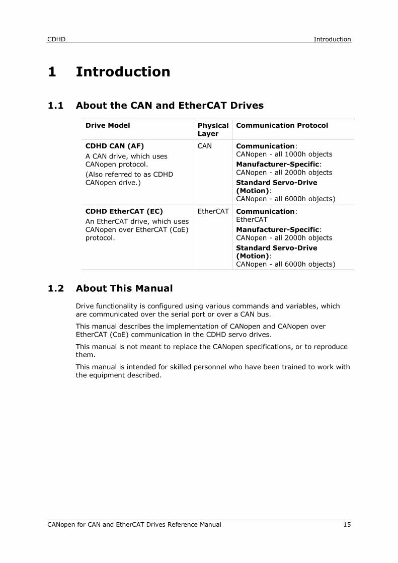
1.1 About the CAN and EtherCAT Drives
Drive Model Physical Layer
Communication Protocol
CDHD CAN (AF) A CAN drive, which uses CANopen protocol. (Also referred to as CDHD CANopen drive.)
CAN Communication: CANopen - all 1000h objects Manufacturer-Specific: CANopen - all 2000h objects Standard Servo-Drive (Motion): CANopen - all 6000h objects)
CDHD EtherCAT (EC) An EtherCAT drive, which uses CANopen over EtherCAT (CoE) protocol.
EtherCAT Communication: EtherCAT Manufacturer-Specific: CANopen - all 2000h objects Standard Servo-Drive (Motion): CANopen - all 6000h objects)
1.2 About This Manual
Drive functionality is configured using various commands and variables, which are communicated over the serial port or over a CAN bus.
This manual describes the implementation of CANopen and CANopen over EtherCAT (CoE) communication in the CDHD servo drives.
This manual is not meant to replace the CANopen specifications, or to reproduce them.
This manual is intended for skilled personnel who have been trained to work with the equipment described.
Introduction CDHD
16 CANopen for CAN and EtherCAT Drives Reference Manual
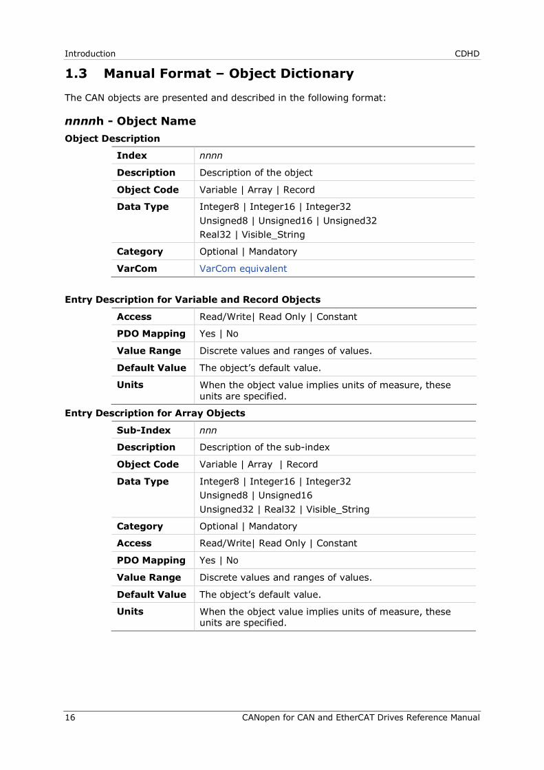
1.3 Manual Format – Object Dictionary
The CAN objects are presented and described in the following format:
nnnnh - Object Name Object Description
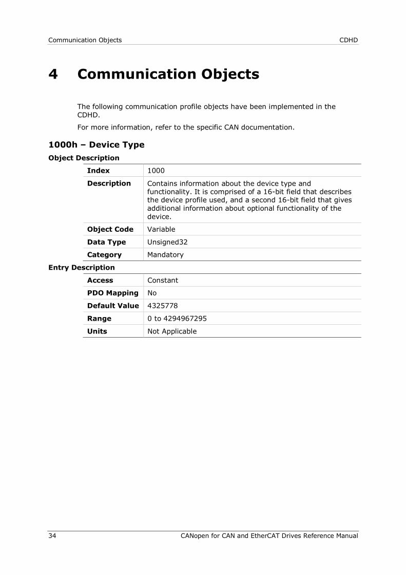
Index nnnn
Description Description of the object
Object Code Variable | Array | Record
Data Type Integer8 | Integer16 | Integer32 Unsigned8 | Unsigned16 | Unsigned32 Real32 | Visible_String
Category Optional | Mandatory
VarCom VarCom equivalent
Entry Description for Variable and Record Objects
Access Read/Write| Read Only | Constant
PDO Mapping Yes | No
Value Range Discrete values and ranges of values.
Default Value The object’s default value.
Units When the object value implies units of measure, these units are specified.
Entry Description for Array Objects
Sub-Index nnn
Description Description of the sub-index
Object Code Variable | Array | Record
Data Type Integer8 | Integer16 | Integer32 Unsigned8 | Unsigned16 Unsigned32 | Real32 | Visible_String
Category Optional | Mandatory
Access Read/Write| Read Only | Constant
PDO Mapping Yes | No
Value Range Discrete values and ranges of values.
Default Value The object’s default value.
Units When the object value implies units of measure, these units are specified.
CDHD Cabling and Setup
CANopen for CAN and EtherCAT Drives Reference Manual 17
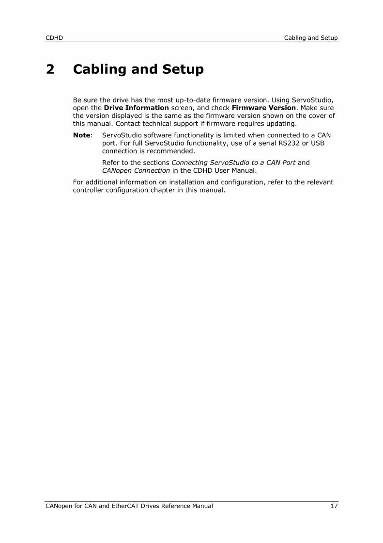
2 Cabling and Setup
Be sure the drive has the most up-to-date firmware version. Using ServoStudio, open the Drive Information screen, and check Firmware Version. Make sure the version displayed is the same as the firmware version shown on the cover of this manual. Contact technical support if firmware requires updating.
Note: ServoStudio software functionality is limited when connected to a CAN port. For full ServoStudio functionality, use of a serial RS232 or USB connection is recommended.
Refer to the sections Connecting ServoStudio to a CAN Port and CANopen Connection in the CDHD User Manual.
For additional information on installation and configuration, refer to the relevant controller configuration chapter in this manual.

Cabling and Setup CDHD
18 CANopen for CAN and EtherCAT Drives Reference Manual
2.1 Hardware Configuration
CDHD - CAN Configuration – Horner Controller – Example
Figure 2-1. CDHD–CAN Configuration – Horner Controller – Example
1 Horner controller 2 CAN bus connector* with following pin assignments
Function CDHD RJ45 Pin Horner Connector Pin CAN High 1 4 CAN Low 2 2 Functional Ground 3 1 CAN Shield 4 3 Functional Ground 5 1
3 RJ45 cables 4 CDHD with internal termination set to 0Ω (towards T) 5 Last CDHD, with internal terminator set to 120Ω (away from T)
* A 120Ω termination resistor is required at the beginning of the chain.
CDHD Cabling and Setup
CANopen for CAN and EtherCAT Drives Reference Manual 19
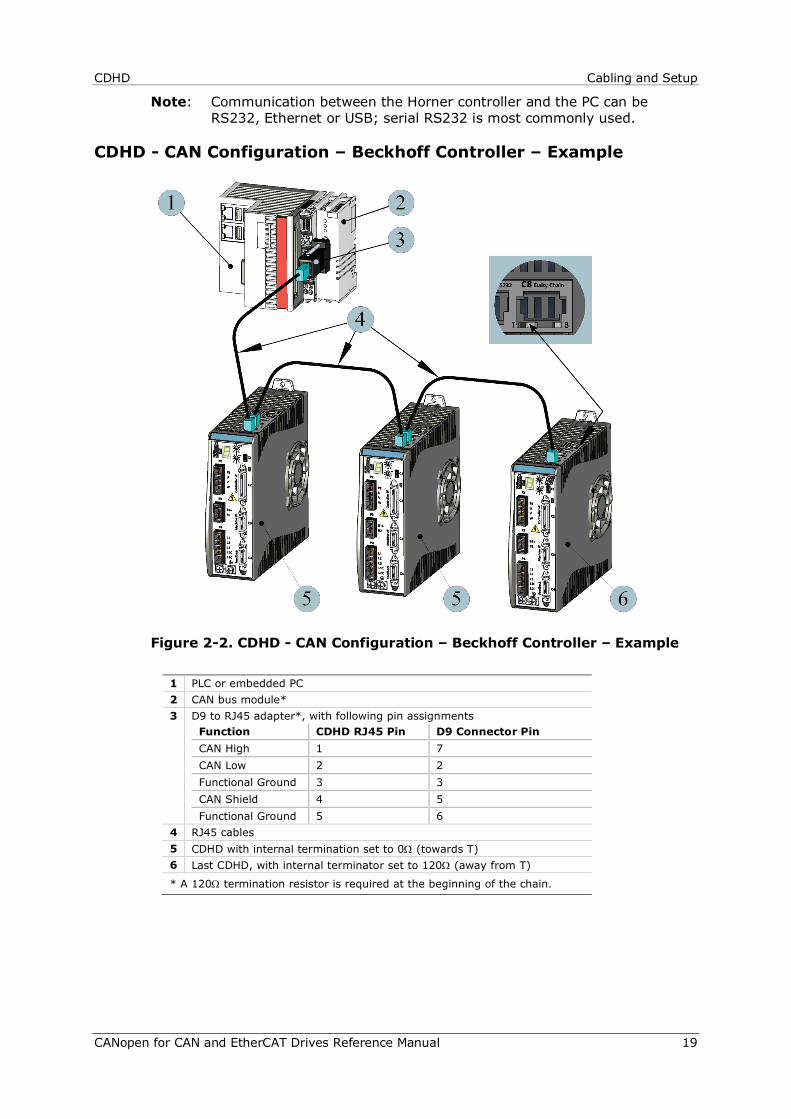
Note: Communication between the Horner controller and the PC can be RS232, Ethernet or USB; serial RS232 is most commonly used.
CDHD - CAN Configuration – Beckhoff Controller – Example
Figure 2-2. CDHD - CAN Configuration – Beckhoff Controller – Example
1 PLC or embedded PC 2 CAN bus module* 3 D9 to RJ45 adapter*, with following pin assignments
Function CDHD RJ45 Pin D9 Connector Pin CAN High 1 7 CAN Low 2 2 Functional Ground 3 3 CAN Shield 4 5 Functional Ground 5 6
4 RJ45 cables 5 CDHD with internal termination set to 0Ω (towards T) 6 Last CDHD, with internal terminator set to 120Ω (away from T)
* A 120Ω termination resistor is required at the beginning of the chain.
Cabling and Setup CDHD
20 CANopen for CAN and EtherCAT Drives Reference Manual
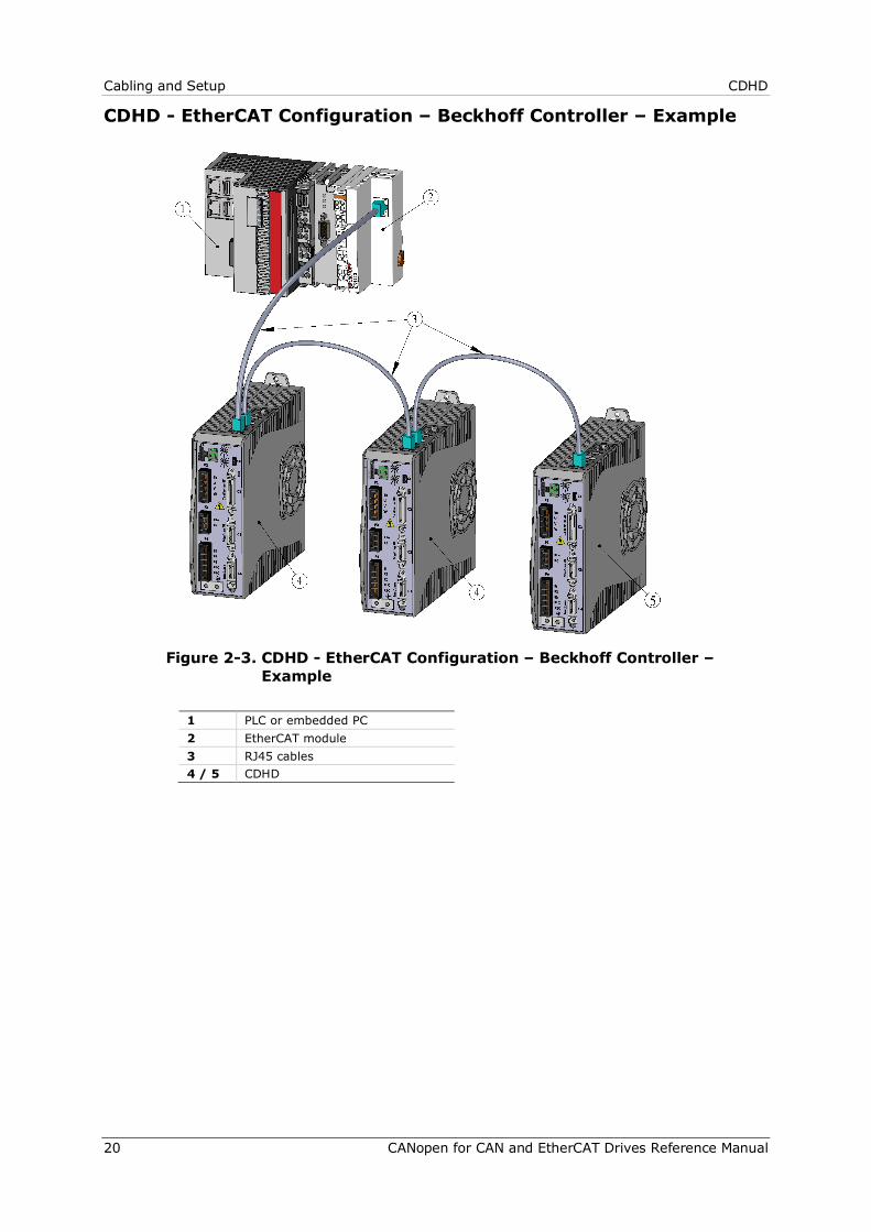
CDHD - EtherCAT Configuration – Beckhoff Controller – Example
Figure 2-3. CDHD - EtherCAT Configuration – Beckhoff Controller –
Example
1 PLC or embedded PC 2 EtherCAT module 3 RJ45 cables 4 / 5 CDHD
CDHD Cabling and Setup
CANopen for CAN and EtherCAT Drives Reference Manual 21
2.2 Node Address
Node Address in CANopen Network Within a CANopen network, a unique node address (identification number) must be allocated to each individual CANopen device.
Two drives in the same CANopen network cannot have the same address.
If two or more drives are connected to the network, address 0 cannot be used. Only a singular drive may have the address 0.
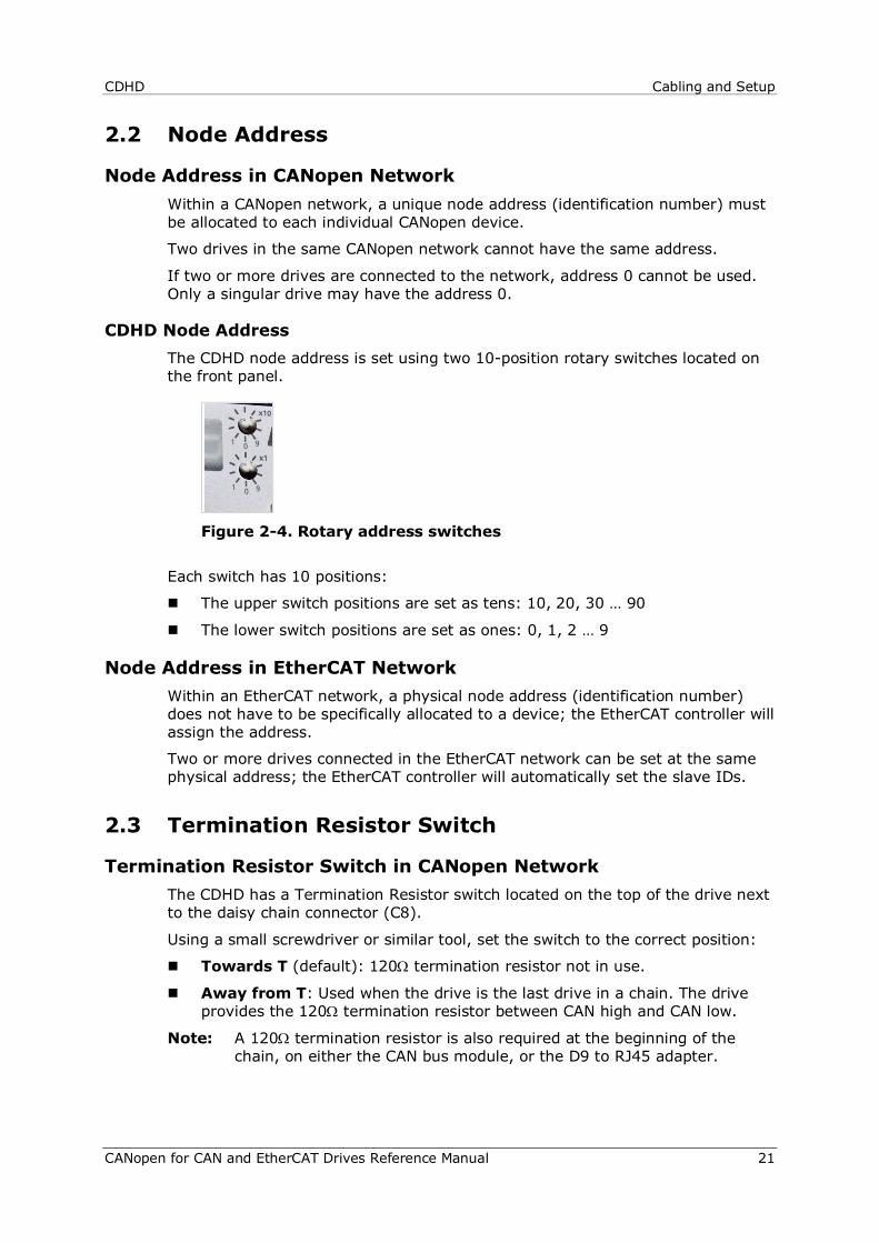
CDHD Node Address The CDHD node address is set using two 10-position rotary switches located on the front panel.
Figure 2-4. Rotary address switches
Each switch has 10 positions:
The upper switch positions are set as tens: 10, 20, 30 … 90
The lower switch positions are set as ones: 0, 1, 2 … 9
Node Address in EtherCAT Network Within an EtherCAT network, a physical node address (identification number) does not have to be specifically allocated to a device; the EtherCAT controller will assign the address.
Two or more drives connected in the EtherCAT network can be set at the same physical address; the EtherCAT controller will automatically set the slave IDs.
2.3 Termination Resistor Switch
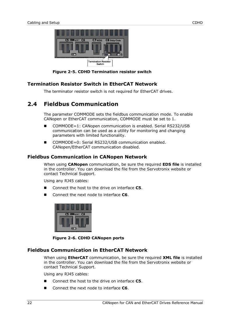
Termination Resistor Switch in CANopen Network The CDHD has a Termination Resistor switch located on the top of the drive next to the daisy chain connector (C8).
Using a small screwdriver or similar tool, set the switch to the correct position:
Towards T (default): 120Ω termination resistor not in use.
Away from T: Used when the drive is the last drive in a chain. The drive provides the 120Ω termination resistor between CAN high and CAN low.
Note: A 120Ω termination resistor is also required at the beginning of the chain, on either the CAN bus module, or the D9 to RJ45 adapter.
Cabling and Setup CDHD
22 CANopen for CAN and EtherCAT Drives Reference Manual
Figure 2-5. CDHD Termination resistor switch
Termination Resistor Switch in EtherCAT Network The terminator resistor switch is not required for EtherCAT drives.
2.4 Fieldbus Communication
The parameter COMMODE sets the fieldbus communication mode. To enable CANopen or EtherCAT communication, COMMODE must be set to 1.
COMMODE=1: CANopen communication is enabled. Serial RS232/USB communication can be used as a utility for monitoring and changing parameters with limited functionality.
COMMODE=0: Serial RS232/USB communication enabled. CANopen/EtherCAT communication disabled.
Fieldbus Communication in CANopen Network When using CANopen communication, be sure the required EDS file is installed in the controller. You can download the file from the Servotronix website or contact Technical Support.
Using any RJ45 cables:
Connect the host to the drive on interface C5.
Connect the next node to interface C6.
Figure 2-6. CDHD CANopen ports
Fieldbus Communication in EtherCAT Network When using EtherCAT communication, be sure the required XML file is installed in the controller. You can download the file from the Servotronix website or contact Technical Support.
Using any RJ45 cables:
Connect the host to the drive on interface C5.
Connect the next node to interface C6.
CDHD Cabling and Setup
CANopen for CAN and EtherCAT Drives Reference Manual 23
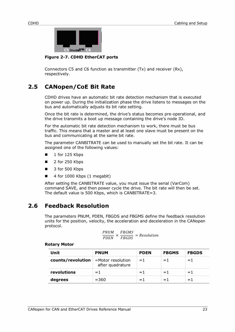
Figure 2-7. CDHD EtherCAT ports
Connectors C5 and C6 function as transmitter (Tx) and receiver (Rx), respectively.
2.5 CANopen/CoE Bit Rate
CDHD drives have an automatic bit rate detection mechanism that is executed on power up. During the initialization phase the drive listens to messages on the bus and automatically adjusts its bit rate setting.
Once the bit rate is determined, the drive’s status becomes pre-operational, and the drive transmits a boot up message containing the drive's node ID.
For the automatic bit rate detection mechanism to work, there must be bus traffic. This means that a master and at least one slave must be present on the bus and communicating at the same bit rate.
The parameter CANBITRATE can be used to manually set the bit rate. It can be assigned one of the following values:
1 for 125 Kbps
2 for 250 Kbps
3 for 500 Kbps
4 for 1000 Kbps (1 megabit)
After setting the CANBITRATE value, you must issue the serial (VarCom) command SAVE, and then power cycle the drive. The bit rate will then be set. The default value is 500 Kbps, which is CANBITRATE=3.
2.6 Feedback Resolution
The parameters PNUM, PDEN, FBGDS and FBGMS define the feedback resolution units for the position, velocity, the acceleration and deceleration in the CANopen protocol.
𝑃𝑁𝑈𝑀𝑃𝐷𝐸𝑁 ×
𝐹𝐵𝐺𝑀𝑆𝐹𝐵𝐺𝐷𝑆 = 𝑅𝑒𝑠𝑜𝑙𝑢𝑡𝑖𝑜𝑛
Rotary Motor
Unit PNUM PDEN FBGMS FBGDS
counts/revolution =Motor resolution after quadrature
=1 =1 =1
revolutions =1 =1 =1 =1
degrees =360 =1 =1 =1

Cabling and Setup CDHD
24 CANopen for CAN and EtherCAT Drives Reference Manual
Linear Motor
Unit PNUM PDEN FBGMS FBGDS
pitch =1 =1 =1 =1
millimeters =MPITCH =1 =1 =1
counts/pitch =Motor resolution after quadrature
=1 =1 =1
Note: If there is no gear box connected to the servo motor, the parameters FBGMS and FBGDS must be set to 1.
Note: Using CANopen or EtherCAT communication protocol, the parameters PNUM, PDEN, FBGDS, FBGMS, FBITPRD and FBITIDX can be set by their respective objects, using SDO Read/Write function blocks. For more information, refer to the chapter Defining Gear Ratio and Feed Constant Parameters.
2.7 Synchronization Mode
The parameter SYNCSOURCE defines the method used to synchronize the drive clock to an external sync signal.
In CDHD EtherCAT drives, SYNCSOURCE must be set to 5 (using ServoStudio Terminal screen. This indicates that the source of the sync signal is an EtherCAT device.
In CDHD CANopen drives, SYNCSOURCE must be set to 6 (using ServoStudio Terminal screen. This indicates that the source of the sync signal is a CANopen device.
2.8 Fieldbus Interpolation Time (Cyclic Synchronous)
The parameters FBITPRD and FBITIDX define, respectively, the interpolation time period and time index used for calculating fieldbus cyclic synch time in Cyclic Synchronous modes of operation.
The following equation defines the relationship of these parameters:
FBITPRD × 10FBITIDX = Fieldbus cyclic synch time, in seconds. It is also possible to set these parameters through the CANopen/EtherCAT SDO objects 0x60C2 sub-index 1 and 0x60C2 sub-index 2
CDHD CANopen Basics
CANopen for CAN and EtherCAT Drives Reference Manual 25
3 CANopen Basics
3.1 Device Communication
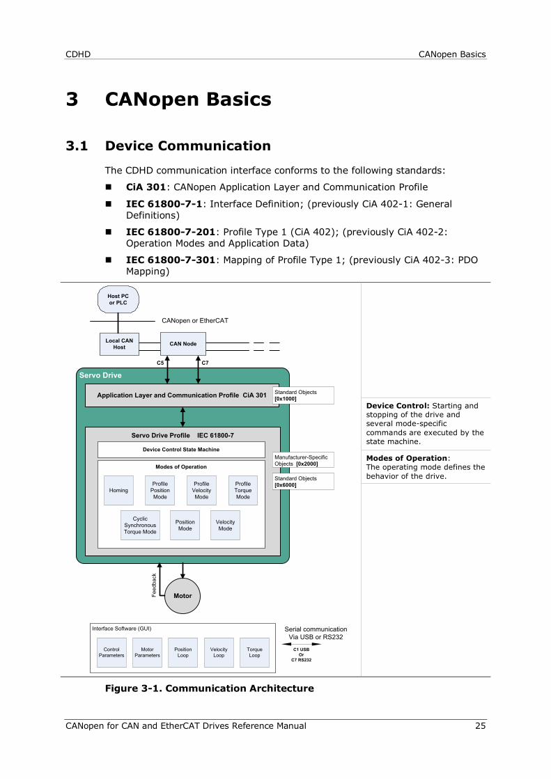
The CDHD communication interface conforms to the following standards:
CiA 301: CANopen Application Layer and Communication Profile
IEC 61800-7-1: Interface Definition; (previously CiA 402-1: General Definitions)
IEC 61800-7-201: Profile Type 1 (CiA 402); (previously CiA 402-2: Operation Modes and Application Data)
IEC 61800-7-301: Mapping of Profile Type 1; (previously CiA 402-3: PDO Mapping)
Device Control: Starting and stopping of the drive and several mode-specific commands are executed by the state machine.
Modes of Operation: The operating mode defines the behavior of the drive.
Figure 3-1. Communication Architecture
Servo Drive
Servo Drive Profile IEC 61800-7
Interface Software (GUI)
CAN NodeLocal CAN Host
Host PCor PLC
Application Layer and Communication Profile CiA 301
CANopen or EtherCAT
Feed
back
Serial communicationVia USB or RS232
C1 USBOr
C7 RS232
Device Control State Machine
Modes of Operation
Profile Position Mode
HomingProfile Torque Mode
Profile Velocity Mode
Motor Parameters
Control Parameters
Velocity Loop
Position Loop
Torque Loop
Manufacturer-Specific Objects [0x2000]
Standard Objects [0x6000]
Standard Objects[0x1000]
Motor
C5 C7
Cyclic Synchronous Torque Mode
Position Mode
Velocity Mode
CANopen Basics CDHD
26 CANopen for CAN and EtherCAT Drives Reference Manual
3.2 Communication Objects
Communication objects are used for exchanging process and service data, for process or system time synchronization, for error state supervision, and for control and monitoring of node states. These objects are defined by their structure, transmission types and their CAN identifier.
Service Data Communication Service data objects (SDOs) provide direct access to object entries in the CANopen device object dictionary. As these object entries contain data of arbitrary size and data type, the SDOs are used to transfer multiple data sets (each containing an arbitrary large block of data) from a client to a server and vice versa. The client controls, via a multiplexer (index and sub-index of the object dictionary), which data set is transferred. The content of the data set is defined within the object dictionary.
In general, an SDO is transferred as a sequence of segments. Prior to transferring the segments there is an initialization phase in which client and server prepare for transferring the segments. For SDOs, it is also possible to transfer a data set of up to four bytes during the initialization phase. This mechanism is called SDO expedited transfer.
The client always initiates an SDO transfer for any type of transfer. The owner of the accessed object dictionary is the server of the SDO. Either the client or the server can take the initiative to abort the transfer of an SDO.
By means of an SDO, a peer-to-peer communication channel between two CANopen devices is established. A CANopen device supports more than one SDO. One supported Server-SDO is the default case (Default SDO).
Process Data Communication Process data objects (PDOs) perform real-time data transfer. The transfer of PDOs is performed without any protocol overhead.
The PDOs correspond to objects in the object dictionary and provide the interface to the application objects. Data type and mapping of application objects into a PDO is determined by a corresponding default PDO mapping structure within the object dictionary. CDHD supports variable PDO mapping; therefore, the number of PDOs and the mapping of application objects into a PDO may be transmitted to a CANopen device during the configuration process, by applying the SDO services to the corresponding objects of the object dictionary.
PDOs are used for both data transmission and data reception – termed Transmit-PDO (TPDO) and Receive-PDO (RPDO), respectively. CANopen devices supporting TPDO are PDO producers, and CANopen devices supporting RPDO are called PDO consumers. CDHD supports both. The PDO communication parameter describes the communication capabilities of the PDO. The PDO mapping parameter contains information about the contents of the PDO.
For each PDO, a pair of communication and mapping parameters is mandatory.
By default 4 TPDOs and 4 RPDOs are implemented in CDHD:
TPDO1
Statusword (6041h), 16 bits
Modes of operation display (6061h)
Torque actual value (6077h), 16 bits

CDHD CANopen Basics
CANopen for CAN and EtherCAT Drives Reference Manual 27
TPDO2
Position actual value (6064h), 32 bits
Velocity actual value (606Ch), 32 bits
TPDO3
Current actual value (6078h), 16 bits
Torque demand command (6074h), 16 bits
Analog input 1 (20F2h), 16 bits
Analog input 2 (20F9h), 16 bits
TPDO4
Digital inputs (60FDh), 32 bits
Position external command (20b6h), 32 bits
RPDO1
Control word (6040h), 16 bits
Mode of operation (6060h), 8 bits
RPDO2
Target position (607Ah), 32 bits
Profile velocity (6081h), 32 bits
RPDO3
Target velocity (60FFh), 32 bits
RPDO4
Target torque (6071h), 16 bit
3.3 Object Units
Table 3-1. Unit Dimensions
Unit Dimension Definition
Position units The units are: (object 6091h sub-index 1 ÷ 6091h sub-index 2) × (object 6092h sub-index 1 ÷ 6092h sub-index 2) For example: Assuming:
object 6091h sub-index 1 = 360 object 6091h sub-index 2 = 1 object 6092h sub-index 1 = 1 object 6092h sub-index 2 = 1
and the actual position reading = 720 Then:
720 ÷ [(360÷1) × (1÷1)] = 2 (= 2 revolutions)
CANopen Basics CDHD
28 CANopen for CAN and EtherCAT Drives Reference Manual
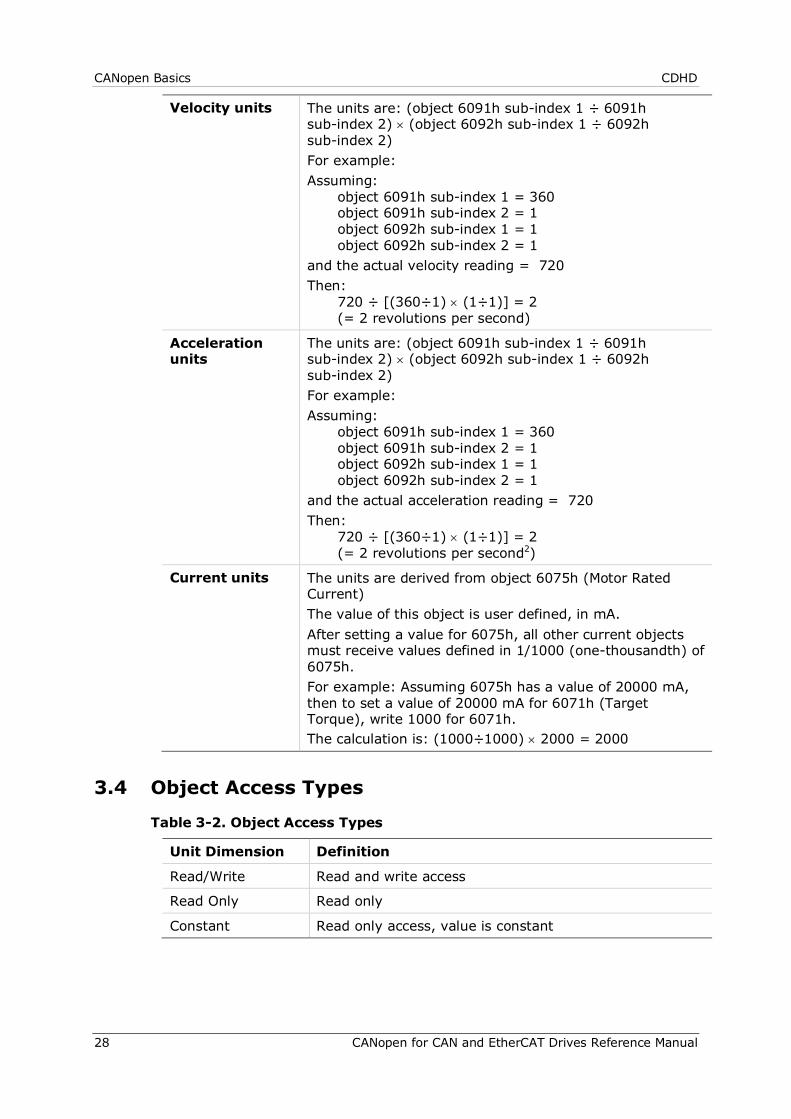
Velocity units The units are: (object 6091h sub-index 1 ÷ 6091h sub-index 2) × (object 6092h sub-index 1 ÷ 6092h sub-index 2) For example: Assuming:
object 6091h sub-index 1 = 360 object 6091h sub-index 2 = 1 object 6092h sub-index 1 = 1 object 6092h sub-index 2 = 1
and the actual velocity reading = 720 Then:
720 ÷ [(360÷1) × (1÷1)] = 2 (= 2 revolutions per second)
Acceleration units
The units are: (object 6091h sub-index 1 ÷ 6091h sub-index 2) × (object 6092h sub-index 1 ÷ 6092h sub-index 2) For example: Assuming:
object 6091h sub-index 1 = 360 object 6091h sub-index 2 = 1 object 6092h sub-index 1 = 1 object 6092h sub-index 2 = 1
and the actual acceleration reading = 720 Then:
720 ÷ [(360÷1) × (1÷1)] = 2 (= 2 revolutions per second2)
Current units The units are derived from object 6075h (Motor Rated Current) The value of this object is user defined, in mA. After setting a value for 6075h, all other current objects must receive values defined in 1/1000 (one-thousandth) of 6075h. For example: Assuming 6075h has a value of 20000 mA, then to set a value of 20000 mA for 6071h (Target Torque), write 1000 for 6071h. The calculation is: (1000÷1000) × 2000 = 2000
3.4 Object Access Types
Table 3-2. Object Access Types
Unit Dimension Definition
Read/Write Read and write access
Read Only Read only
Constant Read only access, value is constant
CDHD CANopen Basics
CANopen for CAN and EtherCAT Drives Reference Manual 29
3.5 Errors and Faults
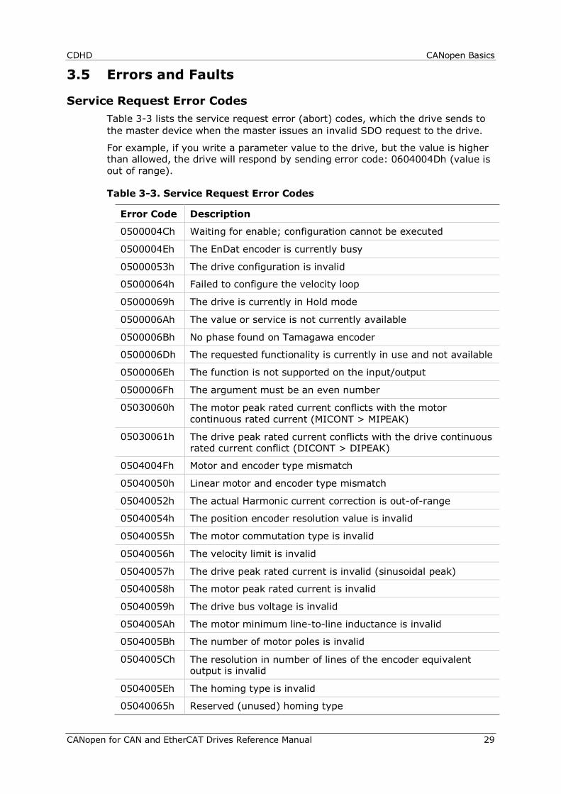
Service Request Error Codes Table 3-3 lists the service request error (abort) codes, which the drive sends to the master device when the master issues an invalid SDO request to the drive.
For example, if you write a parameter value to the drive, but the value is higher than allowed, the drive will respond by sending error code: 0604004Dh (value is out of range).
Table 3-3. Service Request Error Codes
Error Code Description
0500004Ch Waiting for enable; configuration cannot be executed
0500004Eh The EnDat encoder is currently busy
05000053h The drive configuration is invalid
05000064h Failed to configure the velocity loop
05000069h The drive is currently in Hold mode
0500006Ah The value or service is not currently available
0500006Bh No phase found on Tamagawa encoder
0500006Dh The requested functionality is currently in use and not available
0500006Eh The function is not supported on the input/output
0500006Fh The argument must be an even number
05030060h The motor peak rated current conflicts with the motor continuous rated current (MICONT > MIPEAK)
05030061h The drive peak rated current conflicts with the drive continuous rated current conflict (DICONT > DIPEAK)
0504004Fh Motor and encoder type mismatch
05040050h Linear motor and encoder type mismatch
05040052h The actual Harmonic current correction is out-of-range
05040054h The position encoder resolution value is invalid
05040055h The motor commutation type is invalid
05040056h The velocity limit is invalid
05040057h The drive peak rated current is invalid (sinusoidal peak)
05040058h The motor peak rated current is invalid
05040059h The drive bus voltage is invalid
0504005Ah The motor minimum line-to-line inductance is invalid
0504005Bh The number of motor poles is invalid
0504005Ch The resolution in number of lines of the encoder equivalent output is invalid
0504005Eh The homing type is invalid
05040065h Reserved (unused) homing type
CANopen Basics CDHD
30 CANopen for CAN and EtherCAT Drives Reference Manual
06000048h The procedure is not yet completed
06000049h The drive is active
0600004Ah The drive is inactive
0600004Bh The drive is currently busy and cannot execute the command
06000051h Feedback is not properly defined
0600005Fh The operation mode is invalid
06000062h Active disable is in progress
06000067h Password protected
06000068h Burning active
0600006Ch Input/output is not supported
06000070h Saving of parameters failed
06000071h The parameter is not available for modification
06000072h Internal firmware fault
0604004Dh Value is out of range
06040063h The input value must be an integer
06040066h The value is invalid for the current command
0606005D Flash fault occurred
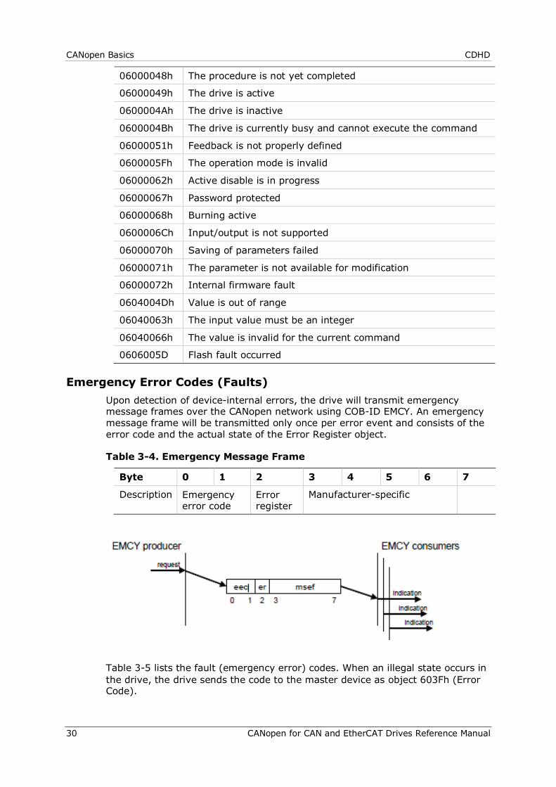
Emergency Error Codes (Faults) Upon detection of device-internal errors, the drive will transmit emergency message frames over the CANopen network using COB-ID EMCY. An emergency message frame will be transmitted only once per error event and consists of the error code and the actual state of the Error Register object.
Table 3-4. Emergency Message Frame
Byte 0 1 2 3 4 5 6 7
Description Emergency error code
Error register
Manufacturer-specific
Table 3-5 lists the fault (emergency error) codes. When an illegal state occurs in the drive, the drive sends the code to the master device as object 603Fh (Error Code).
CDHD CANopen Basics
CANopen for CAN and EtherCAT Drives Reference Manual 31
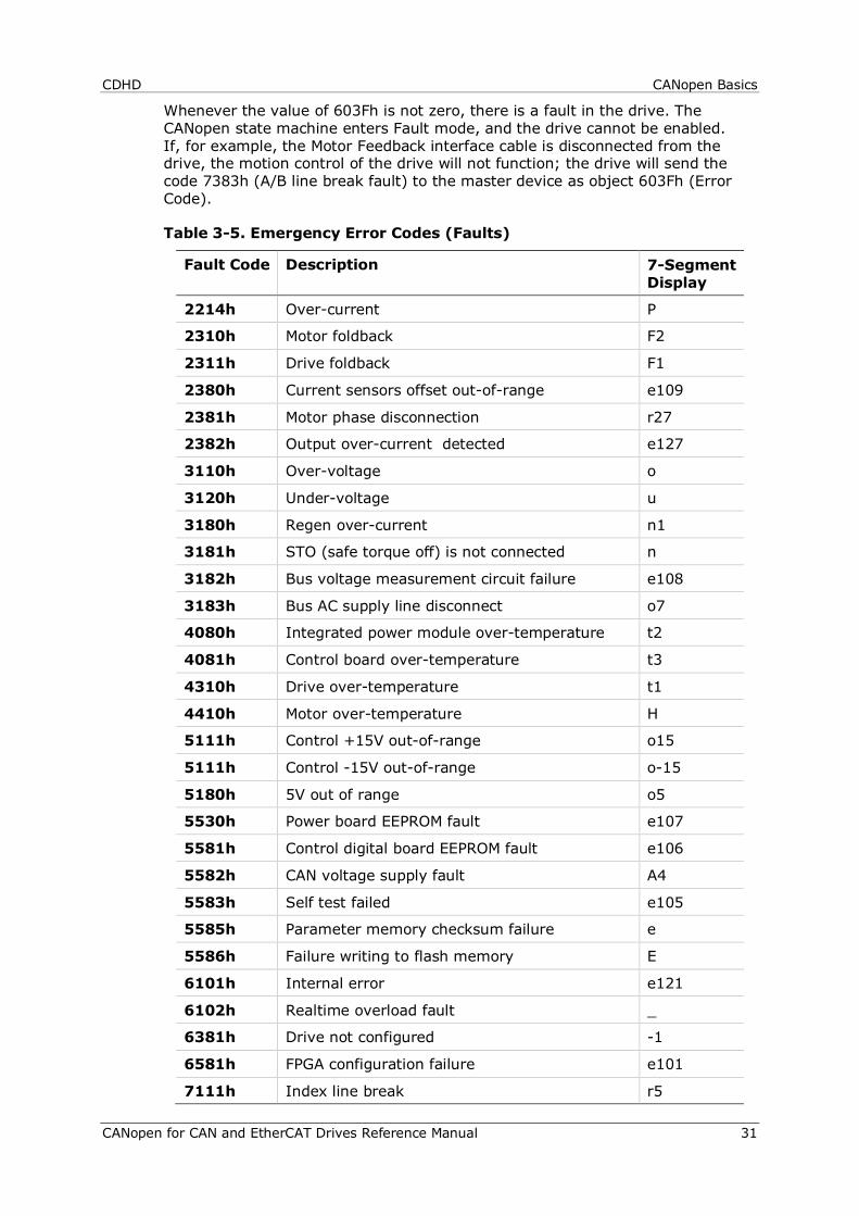
Whenever the value of 603Fh is not zero, there is a fault in the drive. The CANopen state machine enters Fault mode, and the drive cannot be enabled. If, for example, the Motor Feedback interface cable is disconnected from the drive, the motion control of the drive will not function; the drive will send the code 7383h (A/B line break fault) to the master device as object 603Fh (Error Code).
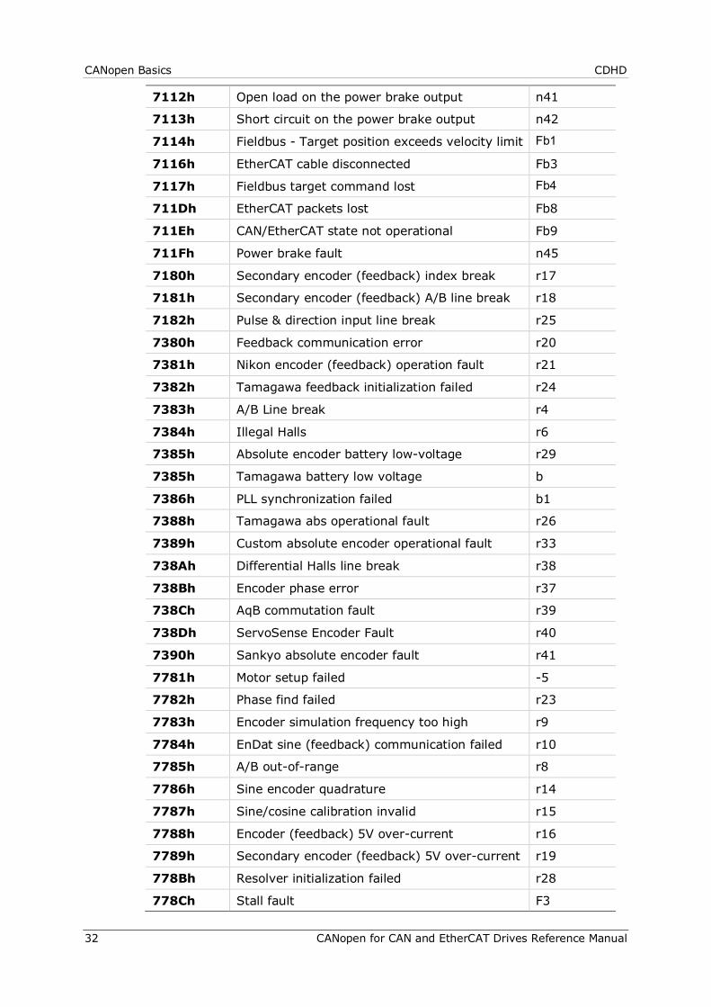
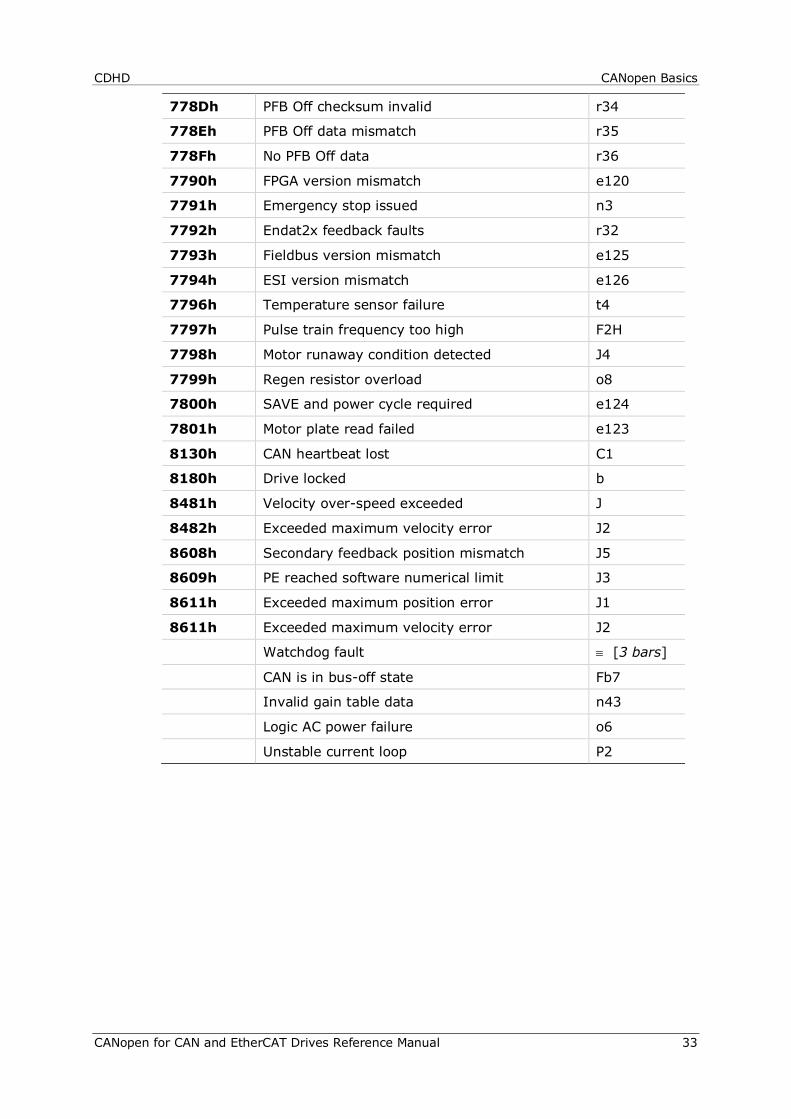
Table 3-5. Emergency Error Codes (Faults)
Fault Code Description 7-Segment Display
2214h Over-current P
2310h Motor foldback F2
2311h Drive foldback F1
2380h Current sensors offset out-of-range e109
2381h Motor phase disconnection r27
2382h Output over-current detected e127
3110h Over-voltage o
3120h Under-voltage u
3180h Regen over-current n1
3181h STO (safe torque off) is not connected n
3182h Bus voltage measurement circuit failure e108
3183h Bus AC supply line disconnect o7
4080h Integrated power module over-temperature t2
4081h Control board over-temperature t3
4310h Drive over-temperature t1
4410h Motor over-temperature H
5111h Control +15V out-of-range o15
5111h Control -15V out-of-range o-15
5180h 5V out of range o5
5530h Power board EEPROM fault e107
5581h Control digital board EEPROM fault e106
5582h CAN voltage supply fault A4
5583h Self test failed e105
5585h Parameter memory checksum failure e
5586h Failure writing to flash memory E
6101h Internal error e121
6102h Realtime overload fault _
6381h Drive not configured -1
6581h FPGA configuration failure e101
7111h Index line break r5
CANopen Basics CDHD
32 CANopen for CAN and EtherCAT Drives Reference Manual
7112h Open load on the power brake output n41
7113h Short circuit on the power brake output n42
7114h Fieldbus - Target position exceeds velocity limit Fb1
7116h EtherCAT cable disconnected Fb3
7117h Fieldbus target command lost Fb4
711Dh EtherCAT packets lost Fb8
711Eh CAN/EtherCAT state not operational Fb9
711Fh Power brake fault n45
7180h Secondary encoder (feedback) index break r17
7181h Secondary encoder (feedback) A/B line break r18
7182h Pulse & direction input line break r25
7380h Feedback communication error r20
7381h Nikon encoder (feedback) operation fault r21
7382h Tamagawa feedback initialization failed r24
7383h A/B Line break r4
7384h Illegal Halls r6
7385h Absolute encoder battery low-voltage r29
7385h Tamagawa battery low voltage b
7386h PLL synchronization failed b1
7388h Tamagawa abs operational fault r26
7389h Custom absolute encoder operational fault r33
738Ah Differential Halls line break r38
738Bh Encoder phase error r37
738Ch AqB commutation fault r39
738Dh ServoSense Encoder Fault r40
7390h Sankyo absolute encoder fault r41
7781h Motor setup failed -5
7782h Phase find failed r23
7783h Encoder simulation frequency too high r9
7784h EnDat sine (feedback) communication failed r10
7785h A/B out-of-range r8
7786h Sine encoder quadrature r14
7787h Sine/cosine calibration invalid r15
7788h Encoder (feedback) 5V over-current r16
7789h Secondary encoder (feedback) 5V over-current r19
778Bh Resolver initialization failed r28
778Ch Stall fault F3
CDHD CANopen Basics
CANopen for CAN and EtherCAT Drives Reference Manual 33
778Dh PFB Off checksum invalid r34
778Eh PFB Off data mismatch r35
778Fh No PFB Off data r36
7790h FPGA version mismatch e120
7791h Emergency stop issued n3
7792h Endat2x feedback faults r32
7793h Fieldbus version mismatch e125
7794h ESI version mismatch e126
7796h Temperature sensor failure t4
7797h Pulse train frequency too high F2H
7798h Motor runaway condition detected J4
7799h Regen resistor overload o8
7800h SAVE and power cycle required e124
7801h Motor plate read failed e123
8130h CAN heartbeat lost C1
8180h Drive locked b
8481h Velocity over-speed exceeded J
8482h Exceeded maximum velocity error J2
8608h Secondary feedback position mismatch J5
8609h PE reached software numerical limit J3
8611h Exceeded maximum position error J1
8611h Exceeded maximum velocity error J2
Watchdog fault ≡ [3 bars]
CAN is in bus-off state Fb7
Invalid gain table data n43
Logic AC power failure o6
Unstable current loop P2
Communication Objects CDHD
34 CANopen for CAN and EtherCAT Drives Reference Manual
4 Communication Objects
The following communication profile objects have been implemented in the CDHD.
For more information, refer to the specific CAN documentation.
1000h – Device Type Object Description
Index 1000
Description Contains information about the device type and functionality. It is comprised of a 16-bit field that describes the device profile used, and a second 16-bit field that gives additional information about optional functionality of the device.
Object Code Variable
Data Type Unsigned32
Category Mandatory
Entry Description
Access Constant
PDO Mapping No
Default Value 4325778
Range 0 to 4294967295
Units Not Applicable
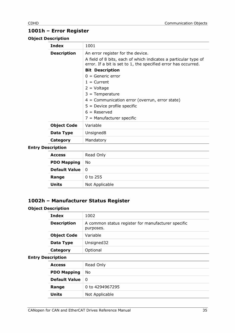
CDHD Communication Objects
CANopen for CAN and EtherCAT Drives Reference Manual 35
1001h – Error Register Object Description
Index 1001
Description An error register for the device. A field of 8 bits, each of which indicates a particular type of error. If a bit is set to 1, the specified error has occurred. Bit Description 0 = Generic error 1 = Current 2 = Voltage 3 = Temperature 4 = Communication error (overrun, error state) 5 = Device profile specific 6 = Reserved 7 = Manufacturer specific
Object Code Variable
Data Type Unsigned8
Category Mandatory
Entry Description
Access Read Only
PDO Mapping No
Default Value 0
Range 0 to 255
Units Not Applicable
1002h – Manufacturer Status Register Object Description
Index 1002
Description A common status register for manufacturer specific purposes.
Object Code Variable
Data Type Unsigned32
Category Optional
Entry Description
Access Read Only
PDO Mapping No
Default Value 0
Range 0 to 4294967295
Units Not Applicable
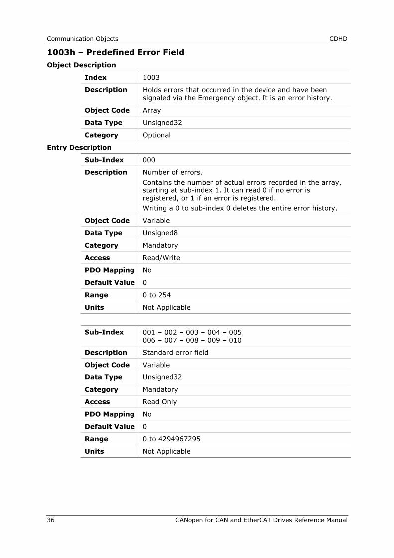
Communication Objects CDHD
36 CANopen for CAN and EtherCAT Drives Reference Manual
1003h – Predefined Error Field Object Description
Index 1003
Description Holds errors that occurred in the device and have been signaled via the Emergency object. It is an error history.
Object Code Array
Data Type Unsigned32
Category Optional
Entry Description
Sub-Index 000
Description Number of errors. Contains the number of actual errors recorded in the array, starting at sub-index 1. It can read 0 if no error is registered, or 1 if an error is registered. Writing a 0 to sub-index 0 deletes the entire error history.
Object Code Variable
Data Type Unsigned8
Category Mandatory
Access Read/Write
PDO Mapping No
Default Value 0
Range 0 to 254
Units Not Applicable
Sub-Index 001 – 002 – 003 – 004 – 005 006 – 007 – 008 – 009 – 010
Description Standard error field
Object Code Variable
Data Type Unsigned32
Category Mandatory
Access Read Only
PDO Mapping No
Default Value 0
Range 0 to 4294967295
Units Not Applicable

CDHD Communication Objects
CANopen for CAN and EtherCAT Drives Reference Manual 37
1005h – COB-ID SYNC Message Object Description
Index 1005
Description Defines the COB-ID of the synchronization object (SYNC). The device generates a SYNC message if bit 30 is set. The meaning of other bits is the same as for other communication objects.
Object Code Variable
Data Type Unsigned32
Category Optional
Entry Description
Access Read/Write
PDO Mapping No
Default Value 128
Range 1 to 4294967295
Units Not Applicable
1006h – Communication Cycle Period Object Description
Index 1006
Description Defines the communication cycle period. It is 0 if not used.
Object Code Variable
Data Type Unsigned32
Category Optional
Entry Description
Access Read/Write
PDO Mapping No
Default Value 0
Range 0 to 4294967295
Units µs
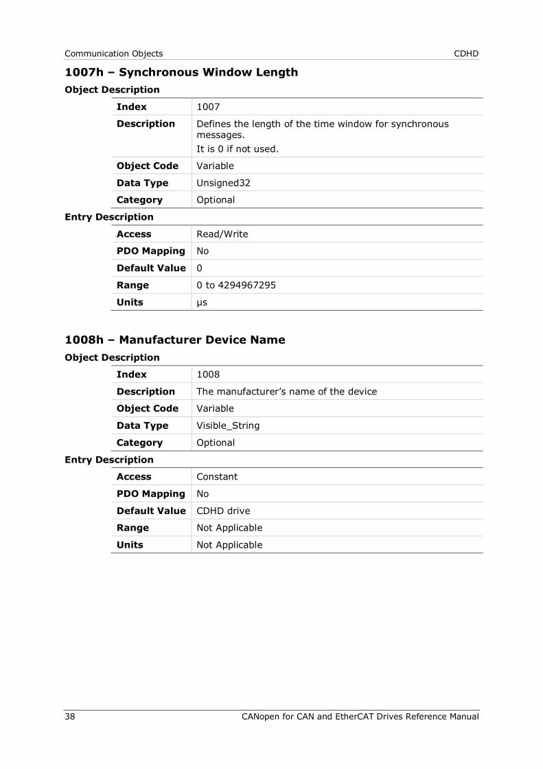
Communication Objects CDHD
38 CANopen for CAN and EtherCAT Drives Reference Manual
1007h – Synchronous Window Length Object Description
Index 1007
Description Defines the length of the time window for synchronous messages. It is 0 if not used.
Object Code Variable
Data Type Unsigned32
Category Optional
Entry Description
Access Read/Write
PDO Mapping No
Default Value 0
Range 0 to 4294967295
Units µs
1008h – Manufacturer Device Name Object Description
Index 1008
Description The manufacturer’s name of the device
Object Code Variable
Data Type Visible_String
Category Optional
Entry Description
Access Constant
PDO Mapping No
Default Value CDHD drive
Range Not Applicable
Units Not Applicable
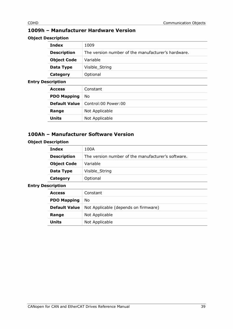
CDHD Communication Objects
CANopen for CAN and EtherCAT Drives Reference Manual 39
1009h – Manufacturer Hardware Version Object Description
Index 1009
Description The version number of the manufacturer’s hardware.
Object Code Variable
Data Type Visible_String
Category Optional
Entry Description
Access Constant
PDO Mapping No
Default Value Control:00 Power:00
Range Not Applicable
Units Not Applicable
100Ah – Manufacturer Software Version Object Description
Index 100A
Description The version number of the manufacturer’s software.
Object Code Variable
Data Type Visible_String
Category Optional
Entry Description
Access Constant
PDO Mapping No
Default Value Not Applicable (depends on firmware)
Range Not Applicable
Units Not Applicable
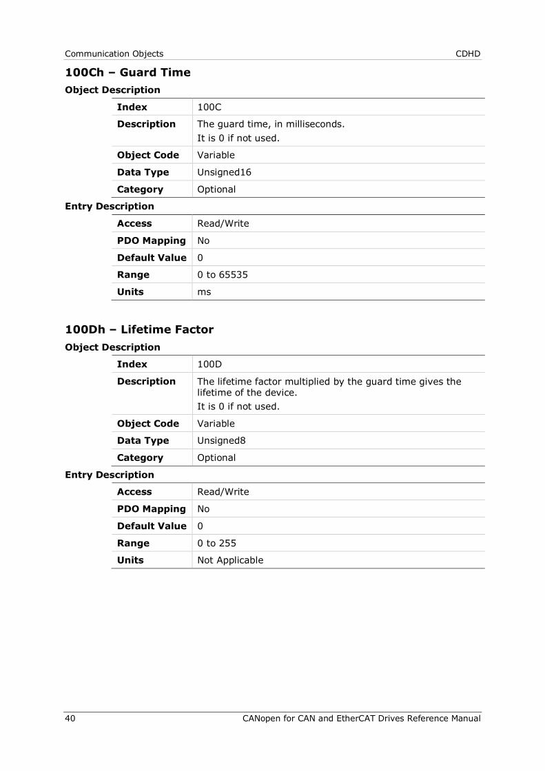
Communication Objects CDHD
40 CANopen for CAN and EtherCAT Drives Reference Manual
100Ch – Guard Time Object Description
Index 100C
Description The guard time, in milliseconds. It is 0 if not used.
Object Code Variable
Data Type Unsigned16
Category Optional
Entry Description
Access Read/Write
PDO Mapping No
Default Value 0
Range 0 to 65535
Units ms
100Dh – Lifetime Factor Object Description
Index 100D
Description The lifetime factor multiplied by the guard time gives the lifetime of the device. It is 0 if not used.
Object Code Variable
Data Type Unsigned8
Category Optional
Entry Description
Access Read/Write
PDO Mapping No
Default Value 0
Range 0 to 255
Units Not Applicable
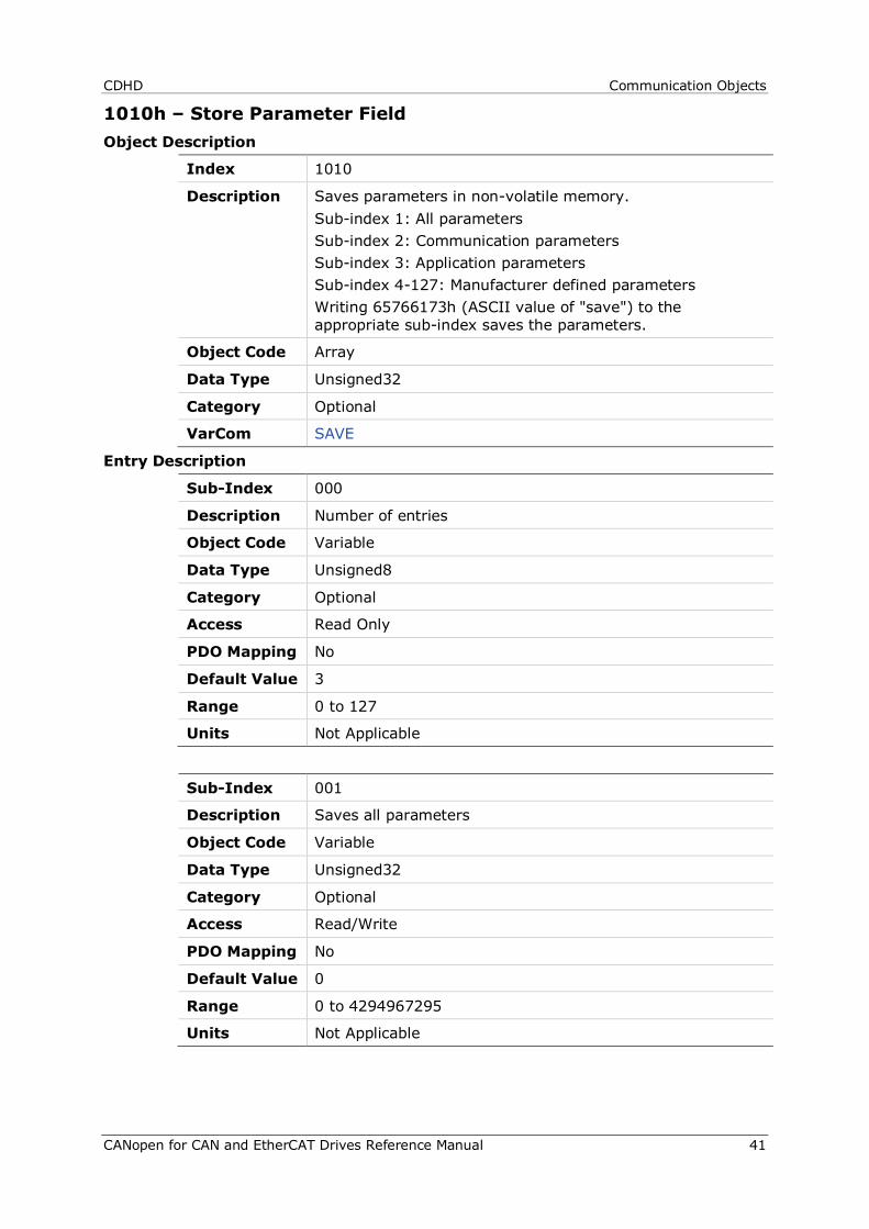
CDHD Communication Objects
CANopen for CAN and EtherCAT Drives Reference Manual 41
1010h – Store Parameter Field Object Description
Index 1010
Description Saves parameters in non-volatile memory. Sub-index 1: All parameters Sub-index 2: Communication parameters Sub-index 3: Application parameters Sub-index 4-127: Manufacturer defined parameters Writing 65766173h (ASCII value of "save") to the appropriate sub-index saves the parameters.
Object Code Array
Data Type Unsigned32
Category Optional
VarCom SAVE
Entry Description
Sub-Index 000
Description Number of entries
Object Code Variable
Data Type Unsigned8
Category Optional
Access Read Only
PDO Mapping No
Default Value 3
Range 0 to 127
Units Not Applicable
Sub-Index 001
Description Saves all parameters
Object Code Variable
Data Type Unsigned32
Category Optional
Access Read/Write
PDO Mapping No
Default Value 0
Range 0 to 4294967295
Units Not Applicable
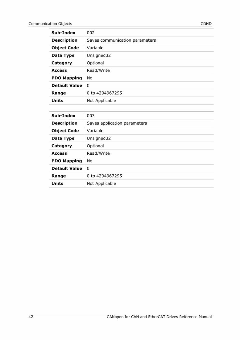
Communication Objects CDHD
42 CANopen for CAN and EtherCAT Drives Reference Manual
Sub-Index 002
Description Saves communication parameters
Object Code Variable
Data Type Unsigned32
Category Optional
Access Read/Write
PDO Mapping No
Default Value 0
Range 0 to 4294967295
Units Not Applicable
Sub-Index 003
Description Saves application parameters
Object Code Variable
Data Type Unsigned32
Category Optional
Access Read/Write
PDO Mapping No
Default Value 0
Range 0 to 4294967295
Units Not Applicable
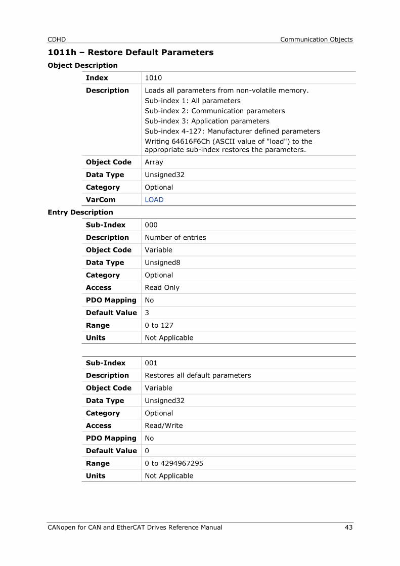
CDHD Communication Objects
CANopen for CAN and EtherCAT Drives Reference Manual 43
1011h – Restore Default Parameters Object Description
Index 1010
Description Loads all parameters from non-volatile memory. Sub-index 1: All parameters Sub-index 2: Communication parameters Sub-index 3: Application parameters Sub-index 4-127: Manufacturer defined parameters Writing 64616F6Ch (ASCII value of "load") to the appropriate sub-index restores the parameters.
Object Code Array
Data Type Unsigned32
Category Optional
VarCom LOAD
Entry Description
Sub-Index 000
Description Number of entries
Object Code Variable
Data Type Unsigned8
Category Optional
Access Read Only
PDO Mapping No
Default Value 3
Range 0 to 127
Units Not Applicable
Sub-Index 001
Description Restores all default parameters
Object Code Variable
Data Type Unsigned32
Category Optional
Access Read/Write
PDO Mapping No
Default Value 0
Range 0 to 4294967295
Units Not Applicable
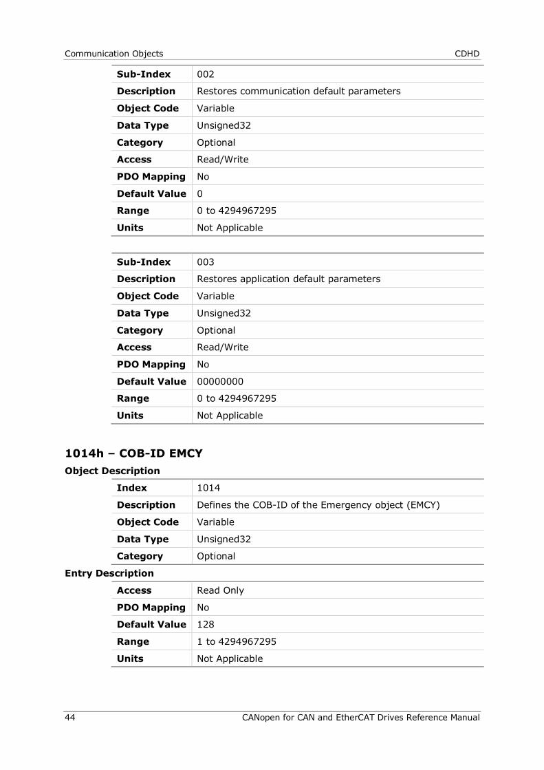
Communication Objects CDHD
44 CANopen for CAN and EtherCAT Drives Reference Manual
Sub-Index 002
Description Restores communication default parameters
Object Code Variable
Data Type Unsigned32
Category Optional
Access Read/Write
PDO Mapping No
Default Value 0
Range 0 to 4294967295
Units Not Applicable
Sub-Index 003
Description Restores application default parameters
Object Code Variable
Data Type Unsigned32
Category Optional
Access Read/Write
PDO Mapping No
Default Value 00000000
Range 0 to 4294967295
Units Not Applicable
1014h – COB-ID EMCY Object Description
Index 1014
Description Defines the COB-ID of the Emergency object (EMCY)
Object Code Variable
Data Type Unsigned32
Category Optional
Entry Description
Access Read Only
PDO Mapping No
Default Value 128
Range 1 to 4294967295
Units Not Applicable
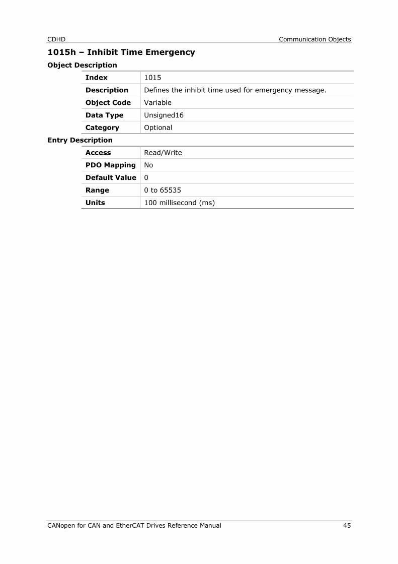
CDHD Communication Objects
CANopen for CAN and EtherCAT Drives Reference Manual 45
1015h – Inhibit Time Emergency Object Description
Index 1015
Description Defines the inhibit time used for emergency message.
Object Code Variable
Data Type Unsigned16
Category Optional
Entry Description
Access Read/Write
PDO Mapping No
Default Value 0
Range 0 to 65535
Units 100 millisecond (ms)
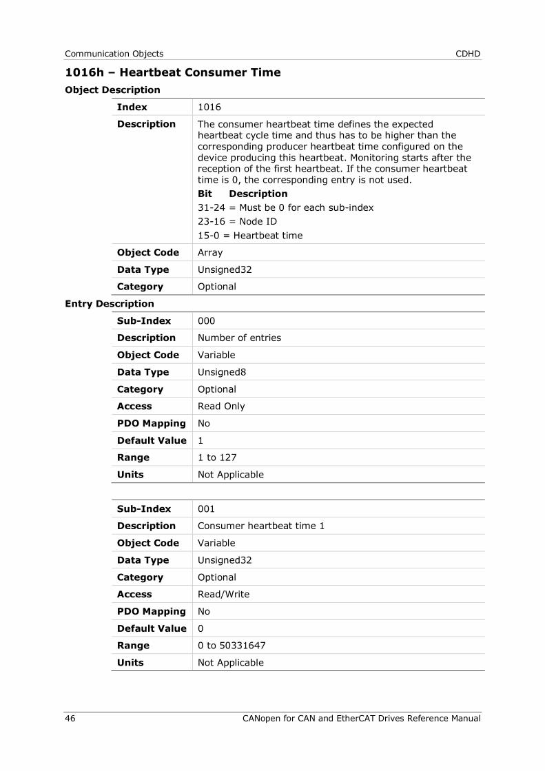
Communication Objects CDHD
46 CANopen for CAN and EtherCAT Drives Reference Manual
1016h – Heartbeat Consumer Time Object Description
Index 1016
Description The consumer heartbeat time defines the expected heartbeat cycle time and thus has to be higher than the corresponding producer heartbeat time configured on the device producing this heartbeat. Monitoring starts after the reception of the first heartbeat. If the consumer heartbeat time is 0, the corresponding entry is not used. Bit Description 31-24 = Must be 0 for each sub-index 23-16 = Node ID 15-0 = Heartbeat time
Object Code Array
Data Type Unsigned32
Category Optional
Entry Description
Sub-Index 000
Description Number of entries
Object Code Variable
Data Type Unsigned8
Category Optional
Access Read Only
PDO Mapping No
Default Value 1
Range 1 to 127
Units Not Applicable
Sub-Index 001
Description Consumer heartbeat time 1
Object Code Variable
Data Type Unsigned32
Category Optional
Access Read/Write
PDO Mapping No
Default Value 0
Range 0 to 50331647
Units Not Applicable
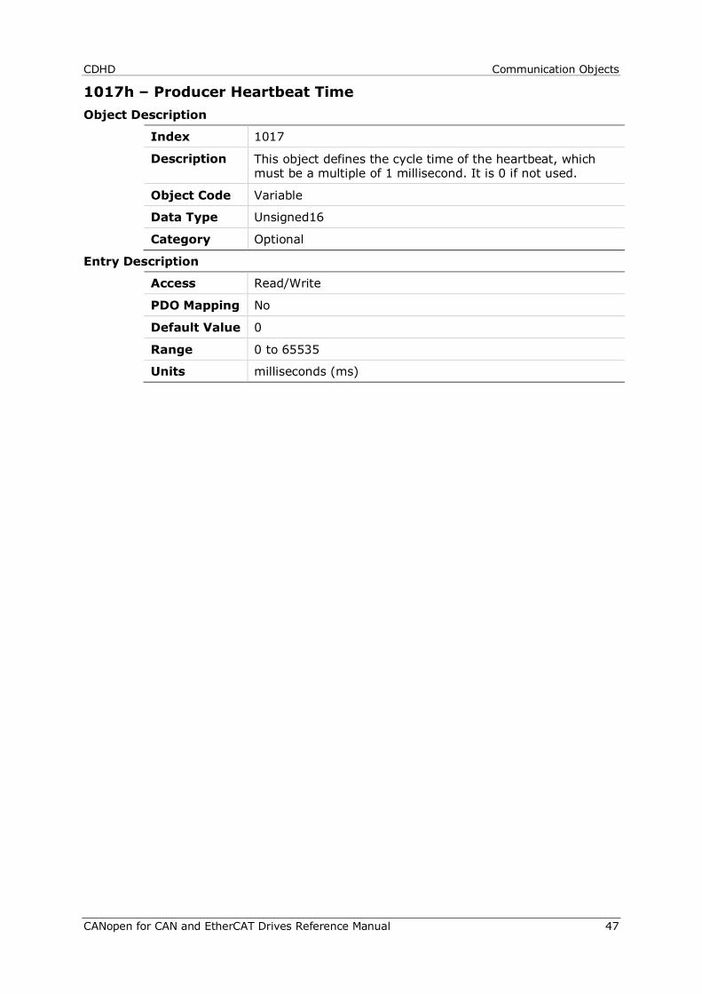
CDHD Communication Objects
CANopen for CAN and EtherCAT Drives Reference Manual 47
1017h – Producer Heartbeat Time Object Description
Index 1017
Description This object defines the cycle time of the heartbeat, which must be a multiple of 1 millisecond. It is 0 if not used.
Object Code Variable
Data Type Unsigned16
Category Optional
Entry Description
Access Read/Write
PDO Mapping No
Default Value 0
Range 0 to 65535
Units milliseconds (ms)
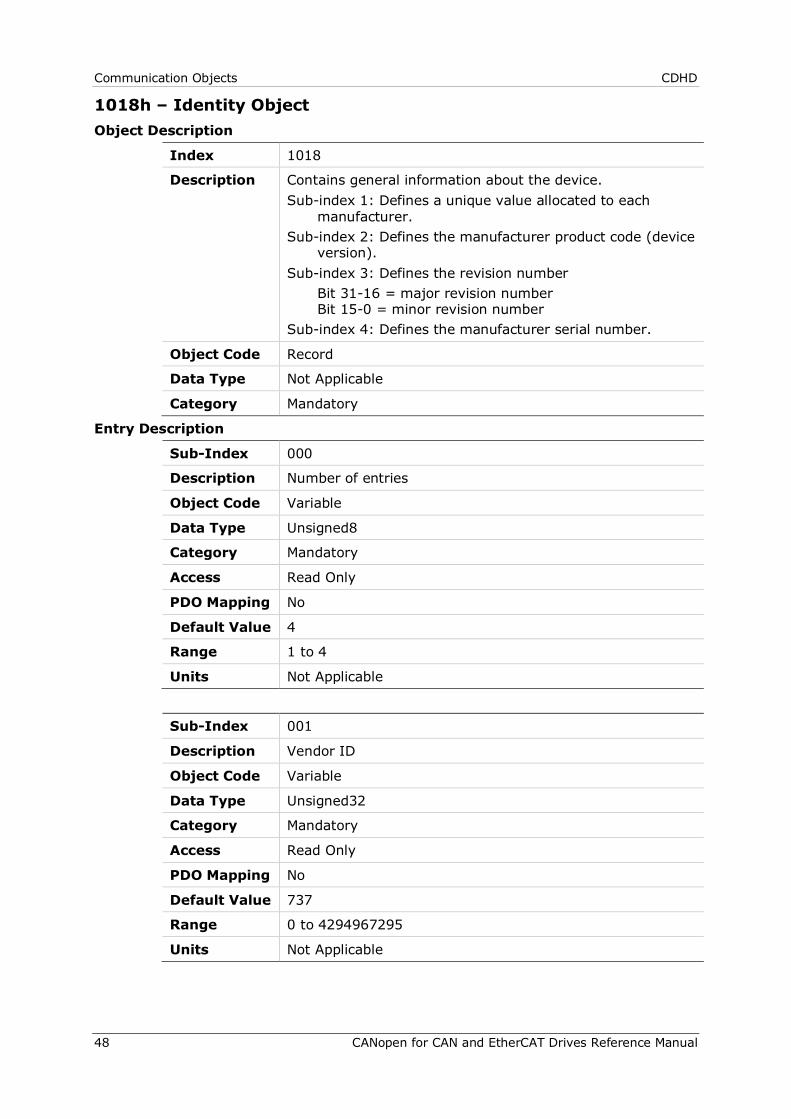
Communication Objects CDHD
48 CANopen for CAN and EtherCAT Drives Reference Manual
1018h – Identity Object Object Description
Index 1018
Description Contains general information about the device. Sub-index 1: Defines a unique value allocated to each
manufacturer. Sub-index 2: Defines the manufacturer product code (device
version). Sub-index 3: Defines the revision number Bit 31-16 = major revision number
Bit 15-0 = minor revision number Sub-index 4: Defines the manufacturer serial number.
Object Code Record
Data Type Not Applicable
Category Mandatory
Entry Description
Sub-Index 000
Description Number of entries
Object Code Variable
Data Type Unsigned8
Category Mandatory
Access Read Only
PDO Mapping No
Default Value 4
Range 1 to 4
Units Not Applicable
Sub-Index 001
Description Vendor ID
Object Code Variable
Data Type Unsigned32
Category Mandatory
Access Read Only
PDO Mapping No
Default Value 737
Range 0 to 4294967295
Units Not Applicable
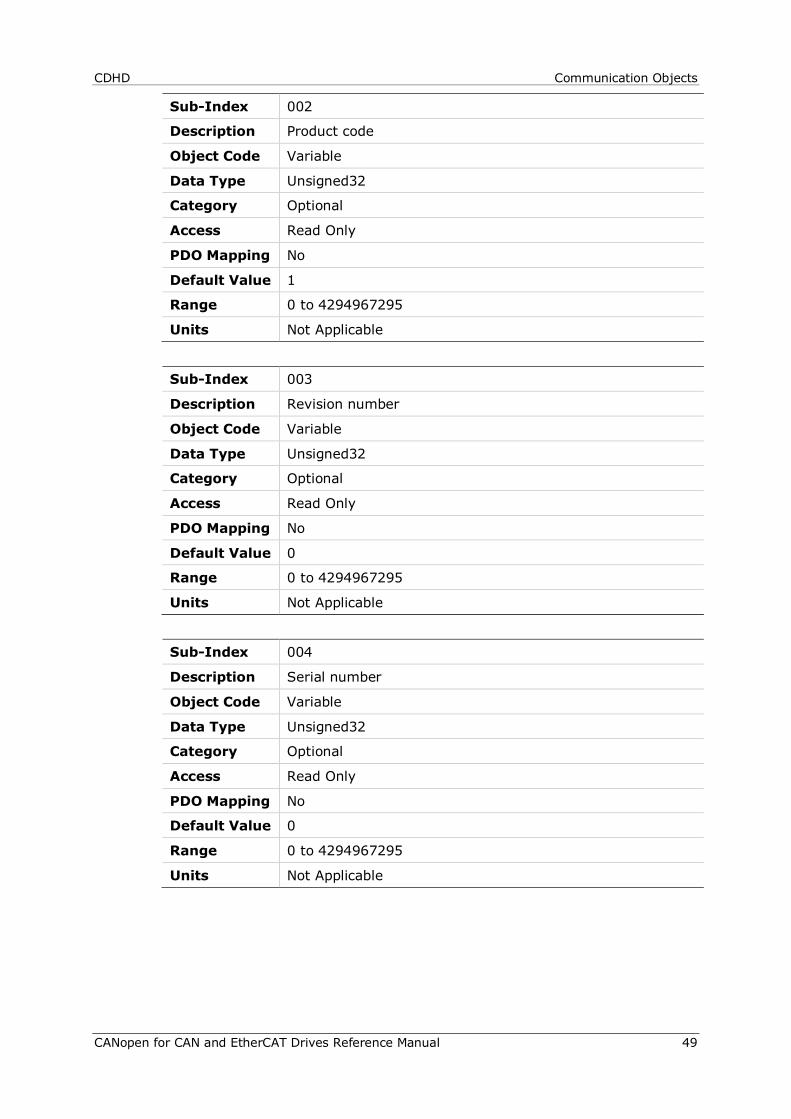
CDHD Communication Objects
CANopen for CAN and EtherCAT Drives Reference Manual 49
Sub-Index 002
Description Product code
Object Code Variable
Data Type Unsigned32
Category Optional
Access Read Only
PDO Mapping No
Default Value 1
Range 0 to 4294967295
Units Not Applicable
Sub-Index 003
Description Revision number
Object Code Variable
Data Type Unsigned32
Category Optional
Access Read Only
PDO Mapping No
Default Value 0
Range 0 to 4294967295
Units Not Applicable
Sub-Index 004
Description Serial number
Object Code Variable
Data Type Unsigned32
Category Optional
Access Read Only
PDO Mapping No
Default Value 0
Range 0 to 4294967295
Units Not Applicable
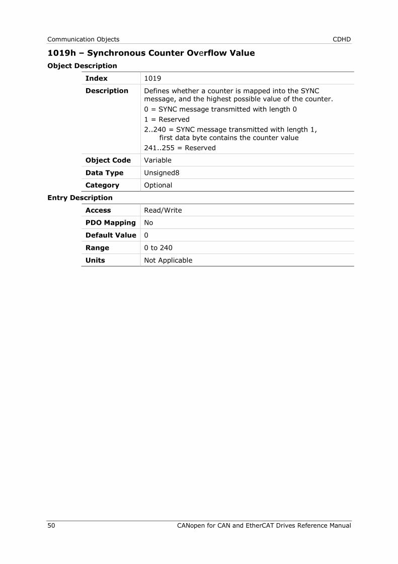
Communication Objects CDHD
50 CANopen for CAN and EtherCAT Drives Reference Manual
1019h – Synchronous Counter Overflow Value Object Description
Index 1019
Description Defines whether a counter is mapped into the SYNC message, and the highest possible value of the counter. 0 = SYNC message transmitted with length 0 1 = Reserved 2..240 = SYNC message transmitted with length 1,
first data byte contains the counter value 241..255 = Reserved
Object Code Variable
Data Type Unsigned8
Category Optional
Entry Description
Access Read/Write
PDO Mapping No
Default Value 0
Range 0 to 240
Units Not Applicable
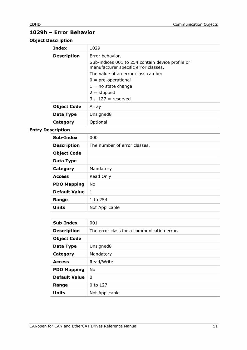
CDHD Communication Objects
CANopen for CAN and EtherCAT Drives Reference Manual 51
1029h – Error Behavior Object Description
Index 1029
Description Error behavior. Sub-indices 001 to 254 contain device profile or manufacturer specific error classes. The value of an error class can be: 0 = pre-operational 1 = no state change 2 = stopped 3 .. 127 = reserved
Object Code Array
Data Type Unsigned8
Category Optional
Entry Description
Sub-Index 000
Description The number of error classes.
Object Code
Data Type
Category Mandatory
Access Read Only
PDO Mapping No
Default Value 1
Range 1 to 254
Units Not Applicable
Sub-Index 001
Description The error class for a communication error.
Object Code
Data Type Unsigned8
Category Mandatory
Access Read/Write
PDO Mapping No
Default Value 0
Range 0 to 127
Units Not Applicable
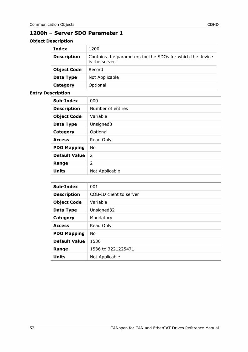
Communication Objects CDHD
52 CANopen for CAN and EtherCAT Drives Reference Manual
1200h – Server SDO Parameter 1 Object Description
Index 1200
Description Contains the parameters for the SDOs for which the device is the server.
Object Code Record
Data Type Not Applicable
Category Optional
Entry Description
Sub-Index 000
Description Number of entries
Object Code Variable
Data Type Unsigned8
Category Optional
Access Read Only
PDO Mapping No
Default Value 2
Range 2
Units Not Applicable
Sub-Index 001
Description COB-ID client to server
Object Code Variable
Data Type Unsigned32
Category Mandatory
Access Read Only
PDO Mapping No
Default Value 1536
Range 1536 to 3221225471
Units Not Applicable
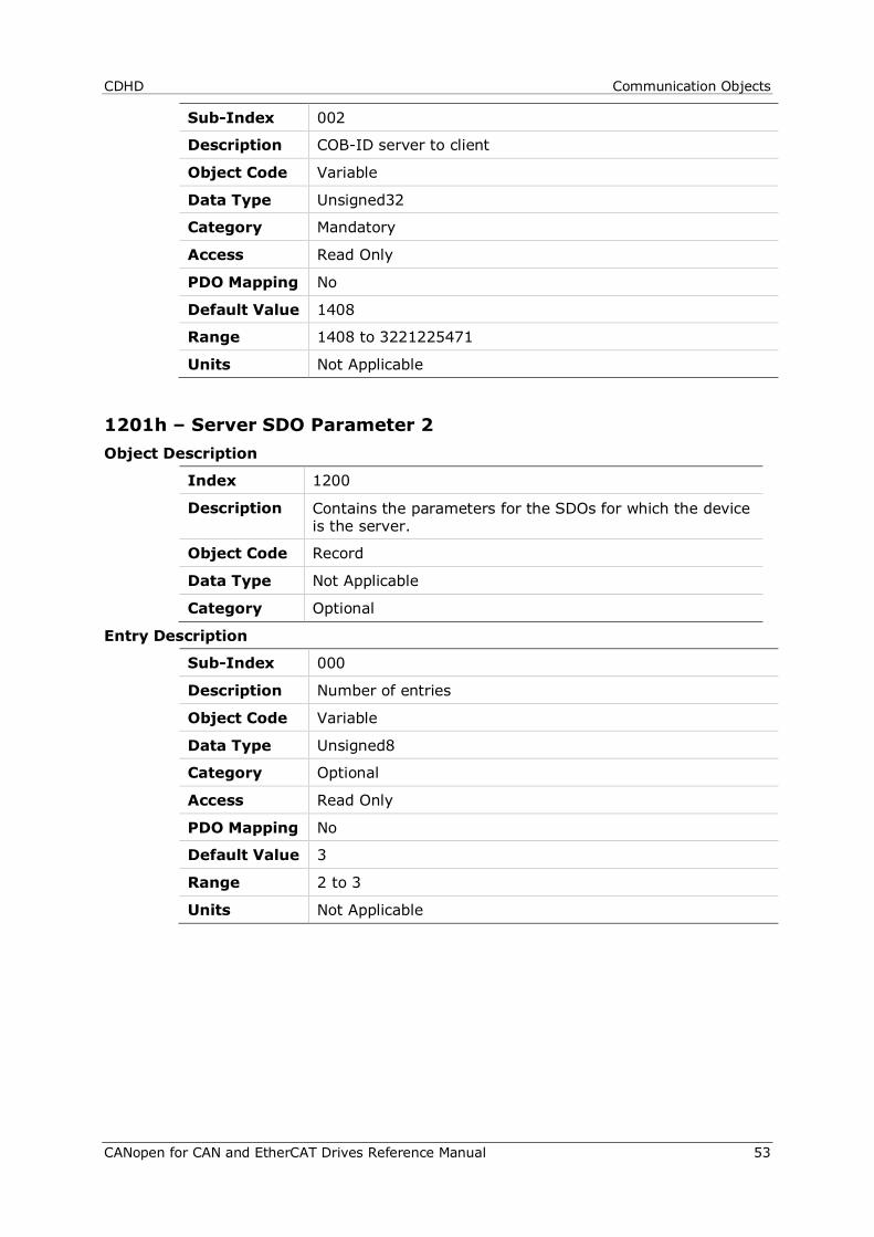
CDHD Communication Objects
CANopen for CAN and EtherCAT Drives Reference Manual 53
Sub-Index 002
Description COB-ID server to client
Object Code Variable
Data Type Unsigned32
Category Mandatory
Access Read Only
PDO Mapping No
Default Value 1408
Range 1408 to 3221225471
Units Not Applicable
1201h – Server SDO Parameter 2 Object Description
Index 1200
Description Contains the parameters for the SDOs for which the device is the server.
Object Code Record
Data Type Not Applicable
Category Optional
Entry Description
Sub-Index 000
Description Number of entries
Object Code Variable
Data Type Unsigned8
Category Optional
Access Read Only
PDO Mapping No
Default Value 3
Range 2 to 3
Units Not Applicable
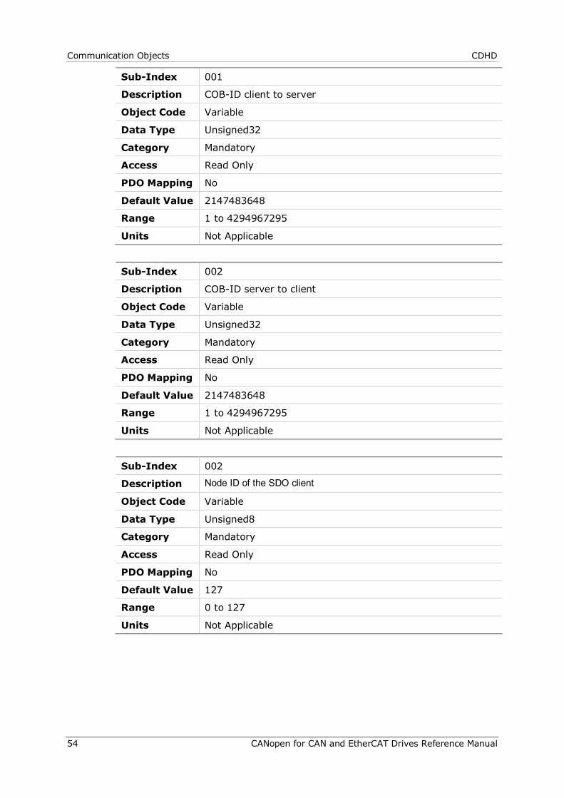
Communication Objects CDHD
54 CANopen for CAN and EtherCAT Drives Reference Manual
Sub-Index 001
Description COB-ID client to server
Object Code Variable
Data Type Unsigned32
Category Mandatory
Access Read Only
PDO Mapping No
Default Value 2147483648
Range 1 to 4294967295
Units Not Applicable
Sub-Index 002
Description COB-ID server to client
Object Code Variable
Data Type Unsigned32
Category Mandatory
Access Read Only
PDO Mapping No
Default Value 2147483648
Range 1 to 4294967295
Units Not Applicable
Sub-Index 002
Description Node ID of the SDO client
Object Code Variable
Data Type Unsigned8
Category Mandatory
Access Read Only
PDO Mapping No
Default Value 127
Range 0 to 127
Units Not Applicable
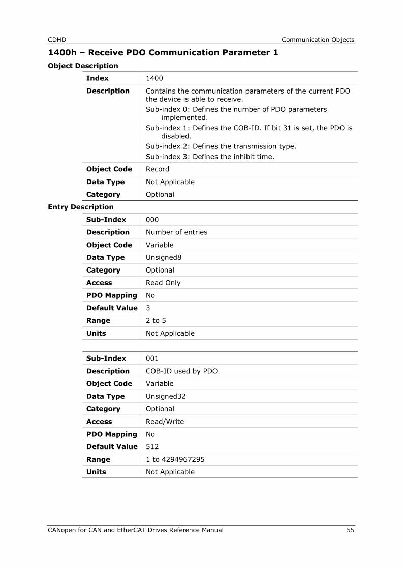
CDHD Communication Objects
CANopen for CAN and EtherCAT Drives Reference Manual 55
1400h – Receive PDO Communication Parameter 1 Object Description
Index 1400
Description Contains the communication parameters of the current PDO the device is able to receive. Sub-index 0: Defines the number of PDO parameters
implemented. Sub-index 1: Defines the COB-ID. If bit 31 is set, the PDO is
disabled. Sub-index 2: Defines the transmission type. Sub-index 3: Defines the inhibit time.
Object Code Record
Data Type Not Applicable
Category Optional
Entry Description
Sub-Index 000
Description Number of entries
Object Code Variable
Data Type Unsigned8
Category Optional
Access Read Only
PDO Mapping No
Default Value 3
Range 2 to 5
Units Not Applicable
Sub-Index 001
Description COB-ID used by PDO
Object Code Variable
Data Type Unsigned32
Category Optional
Access Read/Write
PDO Mapping No
Default Value 512
Range 1 to 4294967295
Units Not Applicable

Communication Objects CDHD
56 CANopen for CAN and EtherCAT Drives Reference Manual
Sub-Index 002
Description Transmission type
Object Code Variable
Data Type Unsigned8
Category Optional
Access Read/Write
PDO Mapping No
Default Value 255
Range 0 to 255
Units Not Applicable
Sub-Index 003
Description Inhibit time
Object Code Variable
Data Type Unsigned16
Category Optional
Access Read/Write
PDO Mapping No
Default Value 0
Range 0 to 65535
Units 100 µs

CDHD Communication Objects
CANopen for CAN and EtherCAT Drives Reference Manual 57
1401h – Receive PDO Communication Parameter 2 Object Description
Index 1401
Description Contains the communication parameters of the current PDO the device is able to receive. Sub-index 0: Defines the number of PDO parameters
implemented. Sub-index 1: Defines the COB-ID. If bit 31 is set, the PDO is
disabled. Sub-index 2: Defines the transmission type. Sub-index 3: Defines the inhibit time.
Object Code Record
Data Type Not Applicable
Category Optional
Entry Description
Sub-Index 000
Description Number of entries
Object Code Variable
Data Type Unsigned8
Category Optional
Access Read Only
PDO Mapping No
Default Value 3
Range 2 to 5
Units Not Applicable
Sub-Index 001
Description COB-ID used by PDO
Object Code Variable
Data Type Unsigned32
Category Optional
Access Read/Write
PDO Mapping No
Default Value 768
Range 1 to 4294967295
Units Not Applicable
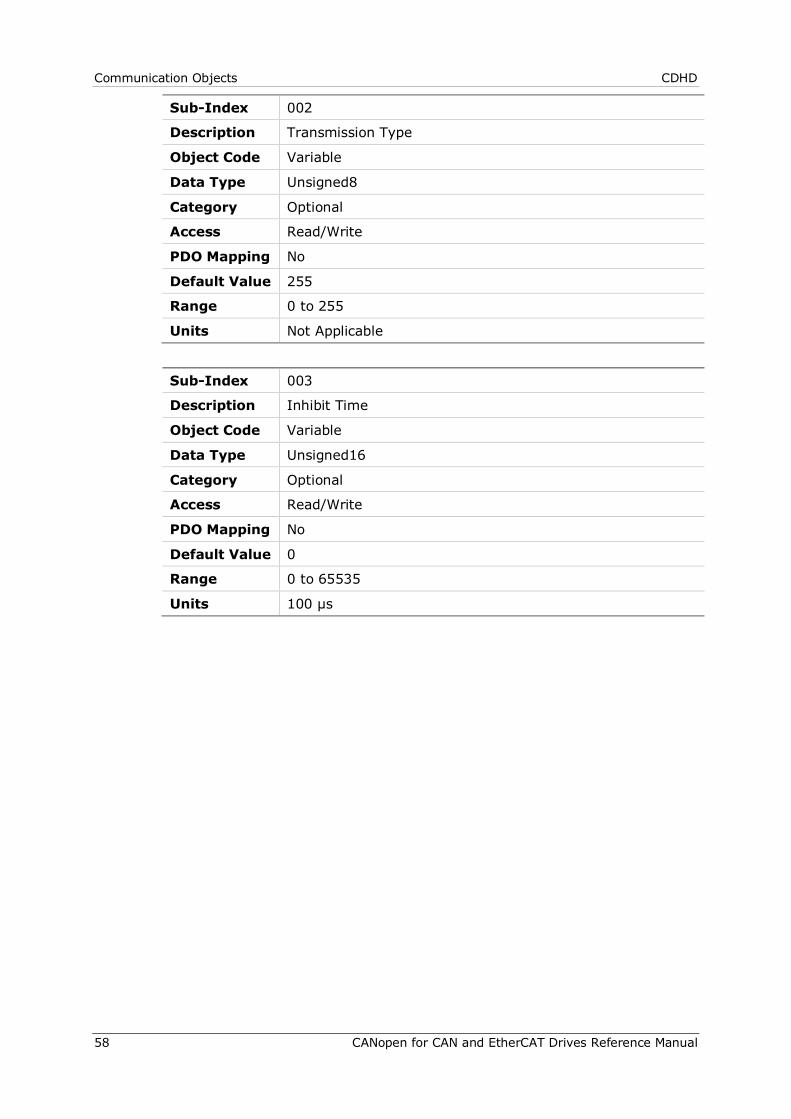
Communication Objects CDHD
58 CANopen for CAN and EtherCAT Drives Reference Manual
Sub-Index 002
Description Transmission Type
Object Code Variable
Data Type Unsigned8
Category Optional
Access Read/Write
PDO Mapping No
Default Value 255
Range 0 to 255
Units Not Applicable
Sub-Index 003
Description Inhibit Time
Object Code Variable
Data Type Unsigned16
Category Optional
Access Read/Write
PDO Mapping No
Default Value 0
Range 0 to 65535
Units 100 µs
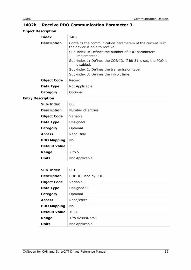
CDHD Communication Objects
CANopen for CAN and EtherCAT Drives Reference Manual 59
1402h – Receive PDO Communication Parameter 3 Object Description
Index 1402
Description Contains the communication parameters of the current PDO the device is able to receive. Sub-index 0: Defines the number of PDO parameters
implemented. Sub-index 1: Defines the COB-ID. If bit 31 is set, the PDO is
disabled. Sub-index 2: Defines the transmission type. Sub-index 3: Defines the inhibit time.
Object Code Record
Data Type Not Applicable
Category Optional
Entry Description
Sub-Index 000
Description Number of entries
Object Code Variable
Data Type Unsigned8
Category Optional
Access Read Only
PDO Mapping No
Default Value 3
Range 2 to 5
Units Not Applicable
Sub-Index 001
Description COB-ID used by PDO
Object Code Variable
Data Type Unsigned32
Category Optional
Access Read/Write
PDO Mapping No
Default Value 1024
Range 1 to 4294967295
Units Not Applicable

Communication Objects CDHD
60 CANopen for CAN and EtherCAT Drives Reference Manual
Sub-Index 002
Description Transmission Type
Object Code Variable
Data Type Unsigned8
Category Optional
Access Read/Write
PDO Mapping No
Default Value 1
Range 0 to 255
Units Not Applicable
Sub-Index 003
Description Inhibit Time
Object Code Variable
Data Type Unsigned16
Category Optional
Access Read/Write
PDO Mapping No
Default Value 0
Range 0 to 65535
Units 100 µs

CDHD Communication Objects
CANopen for CAN and EtherCAT Drives Reference Manual 61
1403h – Receive PDO Communication Parameter 4 Object Description
Index 1403
Description Contains the communication parameters of the current PDO the device is able to receive. Sub-index 0: Defines the number of PDO parameters
implemented. Sub-index 1: Defines the COB-ID. If bit 31 is set, the PDO is
disabled. Sub-index 2: Defines the transmission type. Sub-index 3: Defines the inhibit time.
Object Code Record
Data Type Not Applicable
Category Optional
Entry Description
Sub-Index 000
Description Number of entries
Object Code Variable
Data Type Unsigned8
Category Optional
Access Read Only
PDO Mapping No
Default Value 3
Range 2 to 5
Units Not Applicable
Sub-Index 001
Description COB-ID used by PDO
Object Code Variable
Data Type Unsigned32
Category Optional
Access Read/Write
PDO Mapping No
Default Value 1280
Range 1 to 4294967295
Units Not Applicable

Communication Objects CDHD
62 CANopen for CAN and EtherCAT Drives Reference Manual
Sub-Index 002
Description Transmission Type
Object Code Variable
Data Type Unsigned8
Category Optional
Access Read/Write
PDO Mapping No
Default Value 1
Range 0 to 255
Units Not Applicable
Sub-Index 003
Description Inhibit Time
Object Code Variable
Data Type Unsigned16
Category Optional
Access Read/Write
PDO Mapping No
Default Value 0
Range 0 to 65535
Units 100 µs
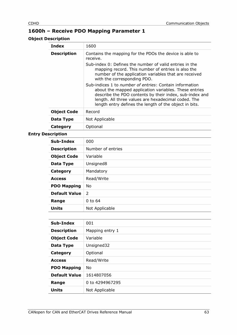
CDHD Communication Objects
CANopen for CAN and EtherCAT Drives Reference Manual 63
1600h – Receive PDO Mapping Parameter 1 Object Description
Index 1600
Description Contains the mapping for the PDOs the device is able to receive. Sub-index 0: Defines the number of valid entries in the
mapping record. This number of entries is also the number of the application variables that are received with the corresponding PDO.
Sub-indices 1 to number of entries: Contain information about the mapped application variables. These entries describe the PDO contents by their index, sub-index and length. All three values are hexadecimal coded. The length entry defines the length of the object in bits.
Object Code Record
Data Type Not Applicable
Category Optional
Entry Description
Sub-Index 000
Description Number of entries
Object Code Variable
Data Type Unsigned8
Category Mandatory
Access Read/Write
PDO Mapping No
Default Value 2
Range 0 to 64
Units Not Applicable
Sub-Index 001
Description Mapping entry 1
Object Code Variable
Data Type Unsigned32
Category Optional
Access Read/Write
PDO Mapping No
Default Value 1614807056
Range 0 to 4294967295
Units Not Applicable
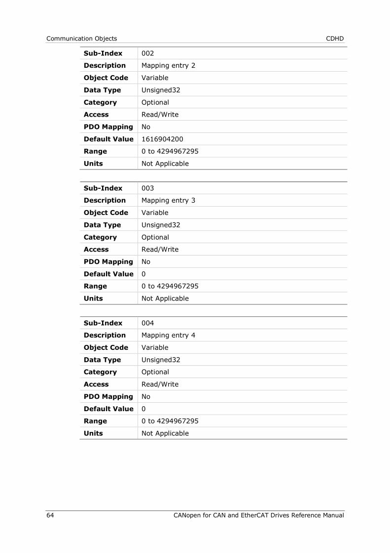
Communication Objects CDHD
64 CANopen for CAN and EtherCAT Drives Reference Manual
Sub-Index 002
Description Mapping entry 2
Object Code Variable
Data Type Unsigned32
Category Optional
Access Read/Write
PDO Mapping No
Default Value 1616904200
Range 0 to 4294967295
Units Not Applicable
Sub-Index 003
Description Mapping entry 3
Object Code Variable
Data Type Unsigned32
Category Optional
Access Read/Write
PDO Mapping No
Default Value 0
Range 0 to 4294967295
Units Not Applicable
Sub-Index 004
Description Mapping entry 4
Object Code Variable
Data Type Unsigned32
Category Optional
Access Read/Write
PDO Mapping No
Default Value 0
Range 0 to 4294967295
Units Not Applicable

CDHD Communication Objects
CANopen for CAN and EtherCAT Drives Reference Manual 65
1601h – Receive PDO Mapping Parameter 2 Object Description
Index 1601
Description Contains the mapping for the PDOs the device is able to receive. Sub-index 0: Defines the number of valid entries in the
mapping record. This number of entries is also the number of the application variables that are received with the corresponding PDO.
Sub-indices 1 to number of entries: Contain information about the mapped application variables. These entries describe the PDO contents by their index, sub-index and length. All three values are hexadecimal coded. The length entry defines the length of the object in bits.
This parameter can be used to verify the overall mapping length. It is mandatory.
Object Code Record
Data Type Not Applicable
Category Optional
Entry Description
Sub-Index 000
Description Number of entries
Object Code Variable
Data Type Unsigned8
Category Mandatory
Access Read/Write
PDO Mapping No
Default Value 2
Range 0 to 64
Units Not Applicable
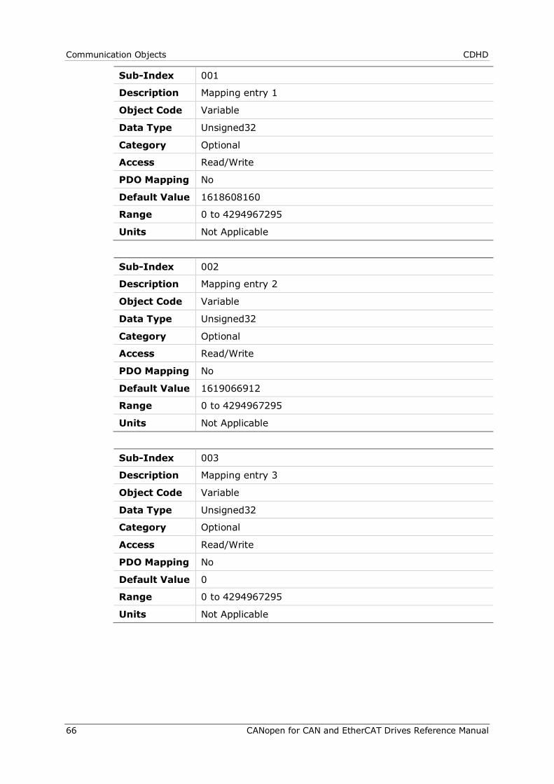
Communication Objects CDHD
66 CANopen for CAN and EtherCAT Drives Reference Manual
Sub-Index 001
Description Mapping entry 1
Object Code Variable
Data Type Unsigned32
Category Optional
Access Read/Write
PDO Mapping No
Default Value 1618608160
Range 0 to 4294967295
Units Not Applicable
Sub-Index 002
Description Mapping entry 2
Object Code Variable
Data Type Unsigned32
Category Optional
Access Read/Write
PDO Mapping No
Default Value 1619066912
Range 0 to 4294967295
Units Not Applicable
Sub-Index 003
Description Mapping entry 3
Object Code Variable
Data Type Unsigned32
Category Optional
Access Read/Write
PDO Mapping No
Default Value 0
Range 0 to 4294967295
Units Not Applicable
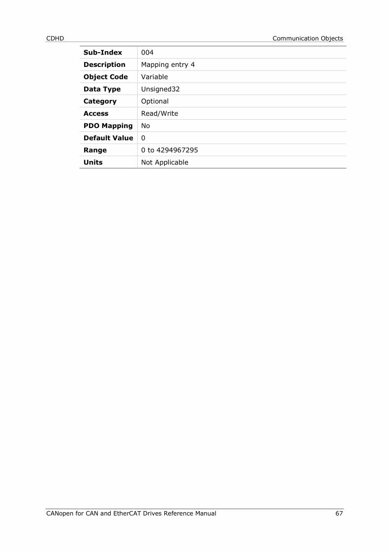
CDHD Communication Objects
CANopen for CAN and EtherCAT Drives Reference Manual 67
Sub-Index 004
Description Mapping entry 4
Object Code Variable
Data Type Unsigned32
Category Optional
Access Read/Write
PDO Mapping No
Default Value 0
Range 0 to 4294967295
Units Not Applicable

Communication Objects CDHD
68 CANopen for CAN and EtherCAT Drives Reference Manual
1602h – Receive PDO Mapping Parameter 3 Object Description
Index 1602
Description Contains the mapping for the PDOs the device is able to receive. Sub-index 0: Defines the number of valid entries in the
mapping record. This number of entries is also the number of the application variables that are received with the corresponding PDO.
Sub-indices 1 to number of entries: Contain information about the mapped application variables. These entries describe the PDO contents by their index, sub-index and length. All three values are hexadecimal coded. The length entry defines the length of the object in bits.
This parameter can be used to verify the overall mapping length. It is mandatory.
Object Code Record
Data Type Not Applicable
Category Optional
Entry Description
Sub-Index 000
Description Number of entries
Object Code Variable
Data Type Unsigned8
Category Mandatory
Access Read/Write
PDO Mapping No
Default Value 1
Range 0 to 64
Units Not Applicable
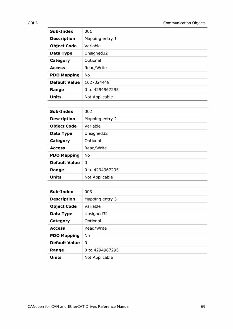
CDHD Communication Objects
CANopen for CAN and EtherCAT Drives Reference Manual 69
Sub-Index 001
Description Mapping entry 1
Object Code Variable
Data Type Unsigned32
Category Optional
Access Read/Write
PDO Mapping No
Default Value 1627324448
Range 0 to 4294967295
Units Not Applicable
Sub-Index 002
Description Mapping entry 2
Object Code Variable
Data Type Unsigned32
Category Optional
Access Read/Write
PDO Mapping No
Default Value 0
Range 0 to 4294967295
Units Not Applicable
Sub-Index 003
Description Mapping entry 3
Object Code Variable
Data Type Unsigned32
Category Optional
Access Read/Write
PDO Mapping No
Default Value 0
Range 0 to 4294967295
Units Not Applicable
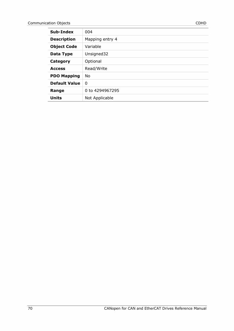
Communication Objects CDHD
70 CANopen for CAN and EtherCAT Drives Reference Manual
Sub-Index 004
Description Mapping entry 4
Object Code Variable
Data Type Unsigned32
Category Optional
Access Read/Write
PDO Mapping No
Default Value 0
Range 0 to 4294967295
Units Not Applicable
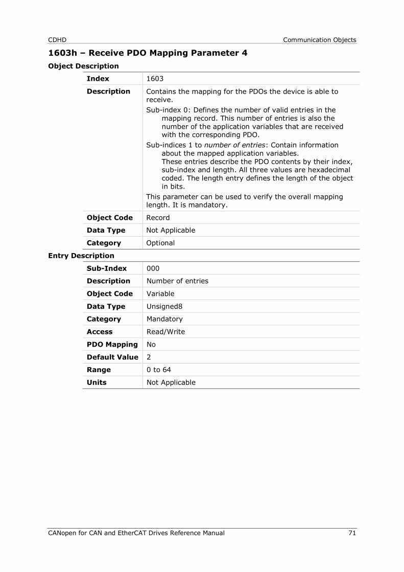
CDHD Communication Objects
CANopen for CAN and EtherCAT Drives Reference Manual 71
1603h – Receive PDO Mapping Parameter 4 Object Description
Index 1603
Description Contains the mapping for the PDOs the device is able to receive. Sub-index 0: Defines the number of valid entries in the
mapping record. This number of entries is also the number of the application variables that are received with the corresponding PDO.
Sub-indices 1 to number of entries: Contain information about the mapped application variables. These entries describe the PDO contents by their index, sub-index and length. All three values are hexadecimal coded. The length entry defines the length of the object in bits.
This parameter can be used to verify the overall mapping length. It is mandatory.
Object Code Record
Data Type Not Applicable
Category Optional
Entry Description
Sub-Index 000
Description Number of entries
Object Code Variable
Data Type Unsigned8
Category Mandatory
Access Read/Write
PDO Mapping No
Default Value 2
Range 0 to 64
Units Not Applicable

Communication Objects CDHD
72 CANopen for CAN and EtherCAT Drives Reference Manual
Sub-Index 001
Description Mapping entry 1
Object Code Variable
Data Type Unsigned32
Category Optional
Access Read/Write
PDO Mapping No
Default Value 1618018320
Range 0 to 4294967295
Units Not Applicable
Sub-Index 002
Description Mapping entry 2
Object Code Variable
Data Type Unsigned32
Category Optional
Access Read/Write
PDO Mapping No
Default Value 1627259168
Range 0 to 4294967295
Units Not Applicable
Sub-Index 003
Description Mapping entry 3
Object Code Variable
Data Type Unsigned32
Category Optional
Access Read/Write
PDO Mapping No
Default Value 0
Range 0 to 4294967295
Units Not Applicable

CDHD Communication Objects
CANopen for CAN and EtherCAT Drives Reference Manual 73
Sub-Index 004
Description Mapping entry 4
Object Code Variable
Data Type Unsigned32
Category Optional
Access Read/Write
PDO Mapping No
Default Value 0
Range 0 to 4294967295
Units Not Applicable

Communication Objects CDHD
74 CANopen for CAN and EtherCAT Drives Reference Manual
1800h – Transmit PDO Communication Parameter 1 Object Description
Index 1800
Description Contains the communication parameters of the current PDO the device is able to transmit. Sub-index 0: Defines the number of PDO parameters
implemented. Sub-index 1: Describes the COB-ID. If bit 31 is set, the PDO
is disabled. Sub-index 2: Defines the transmission type. Sub-index 3: Defines the inhibit time. Sub-index 4: Reserved Sub-index 5: Defines the event time Sub-index 6: Defines the SYNC start value. Start value 0 = SYNC message has no data content. Start value 1 to 240 = SYNC message has 1 byte data.
This data byte is considered a counter value. The SYNC message whose counter value equals the SYNC start value is considered the first received SYNC message.
Object Code Record
Data Type Not Applicable
Category Optional
Entry Description
Sub-Index 000
Description Number of entries
Object Code Variable
Data Type Unsigned8
Category Optional
Access Read Only
PDO Mapping No
Default Value 5
Range 2 to 6
Units Not Applicable

CDHD Communication Objects
CANopen for CAN and EtherCAT Drives Reference Manual 75
Sub-Index 001
Description COB-ID used by PDO
Object Code Variable
Data Type Unsigned32
Category Optional
Access Read/Write
PDO Mapping No
Default Value 384
Range 1 to 4294967295
Units Not Applicable
Sub-Index 002
Description Transmission type
Object Code Variable
Data Type Unsigned8
Category Optional
Access Read/Write
PDO Mapping No
Default Value 1
Range 0 to 255
Units Not Applicable
Sub-Index 003
Description Inhibit time
Variable Variable
Data Type Unsigned16
Category Optional
Access Read/Write
PDO Mapping No
Default Value 0
Range 0 to 65535
Units 100 µs
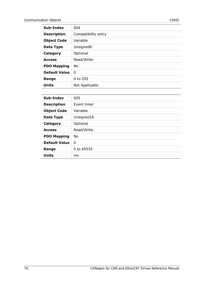
Communication Objects CDHD
76 CANopen for CAN and EtherCAT Drives Reference Manual
Sub-Index 004
Description Compatibility entry
Object Code Variable
Data Type Unsigned8
Category Optional
Access Read/Write
PDO Mapping No
Default Value 0
Range 0 to 255
Units Not Applicable
Sub-Index 005
Description Event timer
Object Code Variable
Data Type Unsigned16
Category Optional
Access Read/Write
PDO Mapping No
Default Value 0
Range 0 to 65535
Units ms
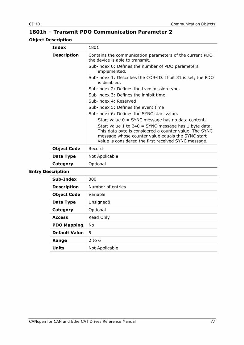
CDHD Communication Objects
CANopen for CAN and EtherCAT Drives Reference Manual 77
1801h – Transmit PDO Communication Parameter 2 Object Description
Index 1801
Description Contains the communication parameters of the current PDO the device is able to transmit. Sub-index 0: Defines the number of PDO parameters
implemented. Sub-index 1: Describes the COB-ID. If bit 31 is set, the PDO
is disabled. Sub-index 2: Defines the transmission type. Sub-index 3: Defines the inhibit time. Sub-index 4: Reserved Sub-index 5: Defines the event time Sub-index 6: Defines the SYNC start value. Start value 0 = SYNC message has no data content. Start value 1 to 240 = SYNC message has 1 byte data.
This data byte is considered a counter value. The SYNC message whose counter value equals the SYNC start value is considered the first received SYNC message.
Object Code Record
Data Type Not Applicable
Category Optional
Entry Description
Sub-Index 000
Description Number of entries
Object Code Variable
Data Type Unsigned8
Category Optional
Access Read Only
PDO Mapping No
Default Value 5
Range 2 to 6
Units Not Applicable
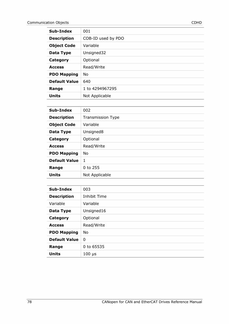
Communication Objects CDHD
78 CANopen for CAN and EtherCAT Drives Reference Manual
Sub-Index 001
Description COB-ID used by PDO
Object Code Variable
Data Type Unsigned32
Category Optional
Access Read/Write
PDO Mapping No
Default Value 640
Range 1 to 4294967295
Units Not Applicable
Sub-Index 002
Description Transmission Type
Object Code Variable
Data Type Unsigned8
Category Optional
Access Read/Write
PDO Mapping No
Default Value 1
Range 0 to 255
Units Not Applicable
Sub-Index 003
Description Inhibit Time
Variable Variable
Data Type Unsigned16
Category Optional
Access Read/Write
PDO Mapping No
Default Value 0
Range 0 to 65535
Units 100 µs
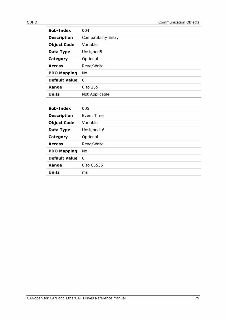
CDHD Communication Objects
CANopen for CAN and EtherCAT Drives Reference Manual 79
Sub-Index 004
Description Compatibility Entry
Object Code Variable
Data Type Unsigned8
Category Optional
Access Read/Write
PDO Mapping No
Default Value 0
Range 0 to 255
Units Not Applicable
Sub-Index 005
Description Event Timer
Object Code Variable
Data Type Unsigned16
Category Optional
Access Read/Write
PDO Mapping No
Default Value 0
Range 0 to 65535
Units ms
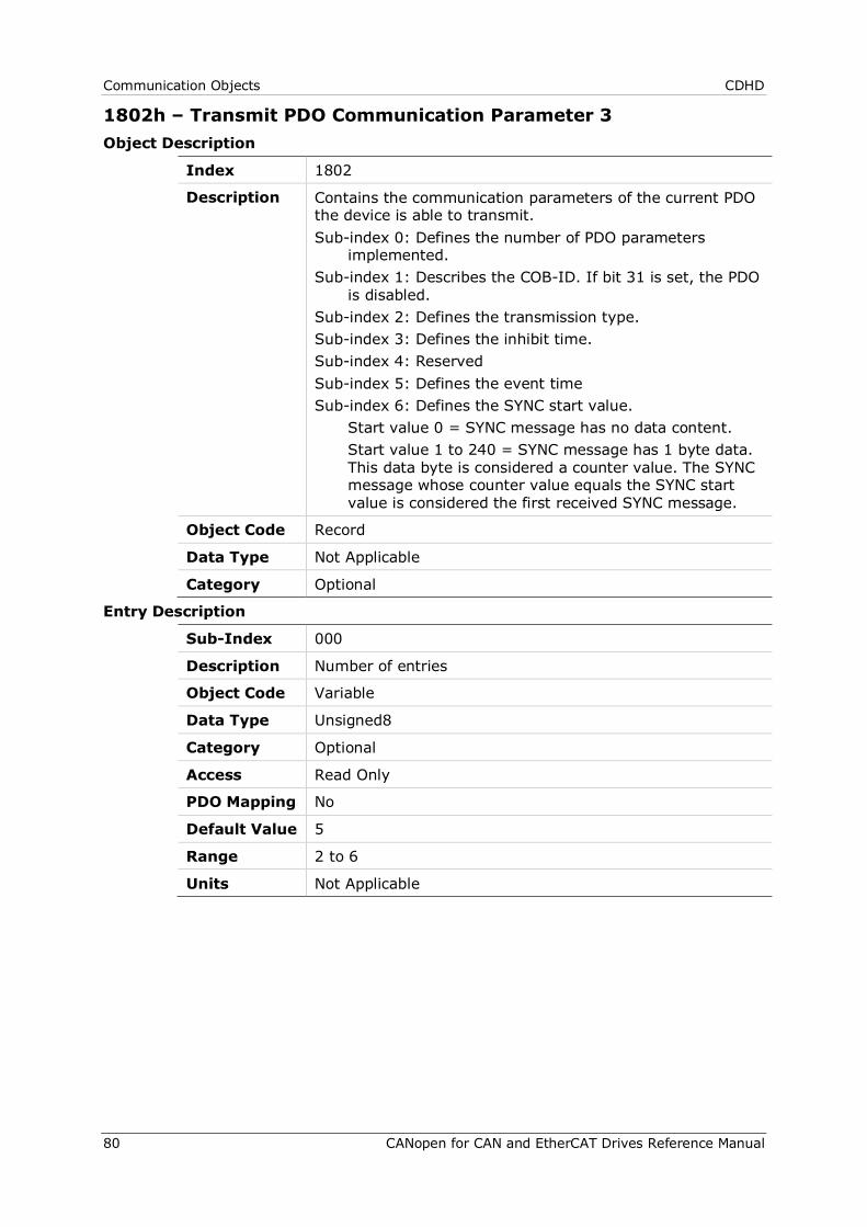
Communication Objects CDHD
80 CANopen for CAN and EtherCAT Drives Reference Manual
1802h – Transmit PDO Communication Parameter 3 Object Description
Index 1802
Description Contains the communication parameters of the current PDO the device is able to transmit. Sub-index 0: Defines the number of PDO parameters
implemented. Sub-index 1: Describes the COB-ID. If bit 31 is set, the PDO
is disabled. Sub-index 2: Defines the transmission type. Sub-index 3: Defines the inhibit time. Sub-index 4: Reserved Sub-index 5: Defines the event time Sub-index 6: Defines the SYNC start value. Start value 0 = SYNC message has no data content. Start value 1 to 240 = SYNC message has 1 byte data.
This data byte is considered a counter value. The SYNC message whose counter value equals the SYNC start value is considered the first received SYNC message.
Object Code Record
Data Type Not Applicable
Category Optional
Entry Description
Sub-Index 000
Description Number of entries
Object Code Variable
Data Type Unsigned8
Category Optional
Access Read Only
PDO Mapping No
Default Value 5
Range 2 to 6
Units Not Applicable
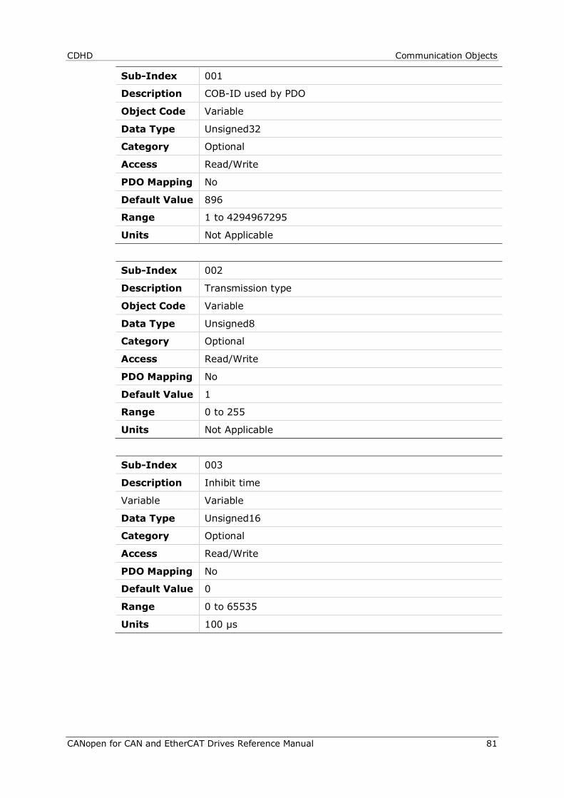
CDHD Communication Objects
CANopen for CAN and EtherCAT Drives Reference Manual 81
Sub-Index 001
Description COB-ID used by PDO
Object Code Variable
Data Type Unsigned32
Category Optional
Access Read/Write
PDO Mapping No
Default Value 896
Range 1 to 4294967295
Units Not Applicable
Sub-Index 002
Description Transmission type
Object Code Variable
Data Type Unsigned8
Category Optional
Access Read/Write
PDO Mapping No
Default Value 1
Range 0 to 255
Units Not Applicable
Sub-Index 003
Description Inhibit time
Variable Variable
Data Type Unsigned16
Category Optional
Access Read/Write
PDO Mapping No
Default Value 0
Range 0 to 65535
Units 100 µs

Communication Objects CDHD
82 CANopen for CAN and EtherCAT Drives Reference Manual
Sub-Index 004
Description Compatibility entry
Object Code Variable
Data Type Unsigned8
Category Optional
Access Read/Write
PDO Mapping No
Default Value 0
Range 0 to 255
Units Not Applicable
Sub-Index 005
Description Event Timer
Object Code Variable
Data Type Unsigned16
Category Optional
Access Read/Write
PDO Mapping No
Default Value 0
Range 0 to 65535
Units ms

CDHD Communication Objects
CANopen for CAN and EtherCAT Drives Reference Manual 83
1803h – Transmit PDO Communication Parameter 4 Object Description
Index 1803
Description Contains the communication parameters of the current PDO the device is able to transmit. Sub-index 0: Defines the number of PDO parameters
implemented. Sub-index 1: Describes the COB-ID. If bit 31 is set, the PDO
is disabled. Sub-index 2: Defines the transmission type. Sub-index 3: Defines the inhibit time. Sub-index 4: Reserved Sub-index 5: Defines the event time Sub-index 6: Defines the SYNC start value. Start value 0 = SYNC message has no data content. Start value 1 to 240 = SYNC message has 1 byte data.
This data byte is considered a counter value. The SYNC message whose counter value equals the SYNC start value is considered the first received SYNC message.
Object Code Record
Data Type Not Applicable
Category Optional
Entry Description
Sub-Index 000
Description Number of entries
Object Code Variable
Data Type Unsigned8
Category Optional
Access Read Only
PDO Mapping No
Default Value 5
Range 2 to 6
Units Not Applicable
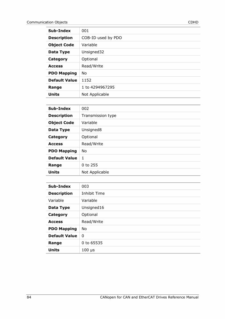
Communication Objects CDHD
84 CANopen for CAN and EtherCAT Drives Reference Manual
Sub-Index 001
Description COB-ID used by PDO
Object Code Variable
Data Type Unsigned32
Category Optional
Access Read/Write
PDO Mapping No
Default Value 1152
Range 1 to 4294967295
Units Not Applicable
Sub-Index 002
Description Transmission type
Object Code Variable
Data Type Unsigned8
Category Optional
Access Read/Write
PDO Mapping No
Default Value 1
Range 0 to 255
Units Not Applicable
Sub-Index 003
Description Inhibit Time
Variable Variable
Data Type Unsigned16
Category Optional
Access Read/Write
PDO Mapping No
Default Value 0
Range 0 to 65535
Units 100 µs

CDHD Communication Objects
CANopen for CAN and EtherCAT Drives Reference Manual 85
Sub-Index 004
Description Compatibility entry
Object Code Variable
Data Type Unsigned8
Category Optional
Access Read/Write
PDO Mapping No
Default Value 0
Range 0 to 255
Units Not Applicable
Sub-Index 005
Description Event timer
Object Code Variable
Data Type Unsigned16
Category Optional
Access Read/Write
PDO Mapping No
Default Value 0
Range 0 to 65535
Units ms
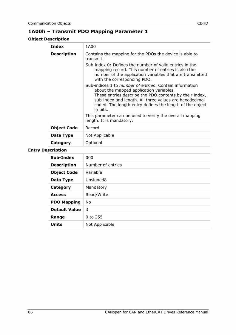
Communication Objects CDHD
86 CANopen for CAN and EtherCAT Drives Reference Manual
1A00h – Transmit PDO Mapping Parameter 1 Object Description
Index 1A00
Description Contains the mapping for the PDOs the device is able to transmit. Sub-index 0: Defines the number of valid entries in the
mapping record. This number of entries is also the number of the application variables that are transmitted with the corresponding PDO.
Sub-indices 1 to number of entries: Contain information about the mapped application variables. These entries describe the PDO contents by their index, sub-index and length. All three values are hexadecimal coded. The length entry defines the length of the object in bits.
This parameter can be used to verify the overall mapping length. It is mandatory.
Object Code Record
Data Type Not Applicable
Category Optional
Entry Description
Sub-Index 000
Description Number of entries
Object Code Variable
Data Type Unsigned8
Category Mandatory
Access Read/Write
PDO Mapping No
Default Value 3
Range 0 to 255
Units Not Applicable

CDHD Communication Objects
CANopen for CAN and EtherCAT Drives Reference Manual 87
Sub-Index 001
Description Mapping entry 1
Object Code Variable
Data Type Unsigned32
Category Optional
Access Read/Write
PDO Mapping No
Default Value 1614872592
Range 0 to 4294967295
Units Not Applicable
Sub-Index 002
Description Mapping entry 2
Object Code Variable
Data Type Unsigned32
Category Optional
Access Read/Write
PDO Mapping No
Default Value 0
Range 0 to 1616969736
Units Not Applicable
Sub-Index 003
Description Mapping entry 3
Object Code Variable
Data Type Unsigned32
Category Optional
Access Read/Write
PDO Mapping No
Default Value 0
Range 0 to 4294967295
Units Not Applicable

Communication Objects CDHD
88 CANopen for CAN and EtherCAT Drives Reference Manual
Sub-Index 004
Description Mapping entry 4
Object Code Variable
Data Type Unsigned32
Category Optional
Access Read/Write
PDO Mapping No
Default Value 0
Range 0 to 4294967295
Units Not Applicable

CDHD Communication Objects
CANopen for CAN and EtherCAT Drives Reference Manual 89
1A01h – Transmit PDO Mapping Parameter 2 Object Description
Index 1A01
Description Contains the mapping for the PDOs the device is able to transmit. Sub-index 0: Defines the number of valid entries in the
mapping record. This number of entries is also the number of the application variables that are transmitted with the corresponding PDO.
Sub-indices 1 to number of entries: Contain information about the mapped application variables. These entries describe the PDO contents by their index, sub-index and length. All three values are hexadecimal coded. The length entry defines the length of the object in bits.
This parameter can be used to verify the overall mapping length. It is mandatory.
Object Code Record
Data Type Not Applicable
Category Optional
Entry Description
Sub-Index 000
Description Number of entries
Object Code Variable
Data Type Unsigned8
Category Mandatory
Access Read/Write
PDO Mapping No
Default Value 2
Range 0 to 255
Units Not Applicable

Communication Objects CDHD
90 CANopen for CAN and EtherCAT Drives Reference Manual
Sub-Index 001
Description Mapping entry 1
Object Code Variable
Data Type Unsigned32
Category Optional
Access Read/Write
PDO Mapping No
Default Value 1617166368
Range 0 to 4294967295
Units Not Applicable
Sub-Index 002
Description Mapping entry 2
Object Code Variable
Data Type Unsigned32
Category Optional
Access Read/Write
PDO Mapping No
Default Value 1617690656
Range 0 to 4294967295
Units Not Applicable
Sub-Index 003
Description Mapping entry 3
Object Code Variable
Data Type Unsigned32
Category Optional
Access Read/Write
PDO Mapping No
Default Value 0
Range 0 to 4294967295
Units Not Applicable

CDHD Communication Objects
CANopen for CAN and EtherCAT Drives Reference Manual 91
Sub-Index 004
Description Mapping entry 4
Object Code Variable
Data Type Unsigned32
Category Optional
Access Read/Write
PDO Mapping No
Default Value 0
Range 0 to 4294967295
Units Not Applicable
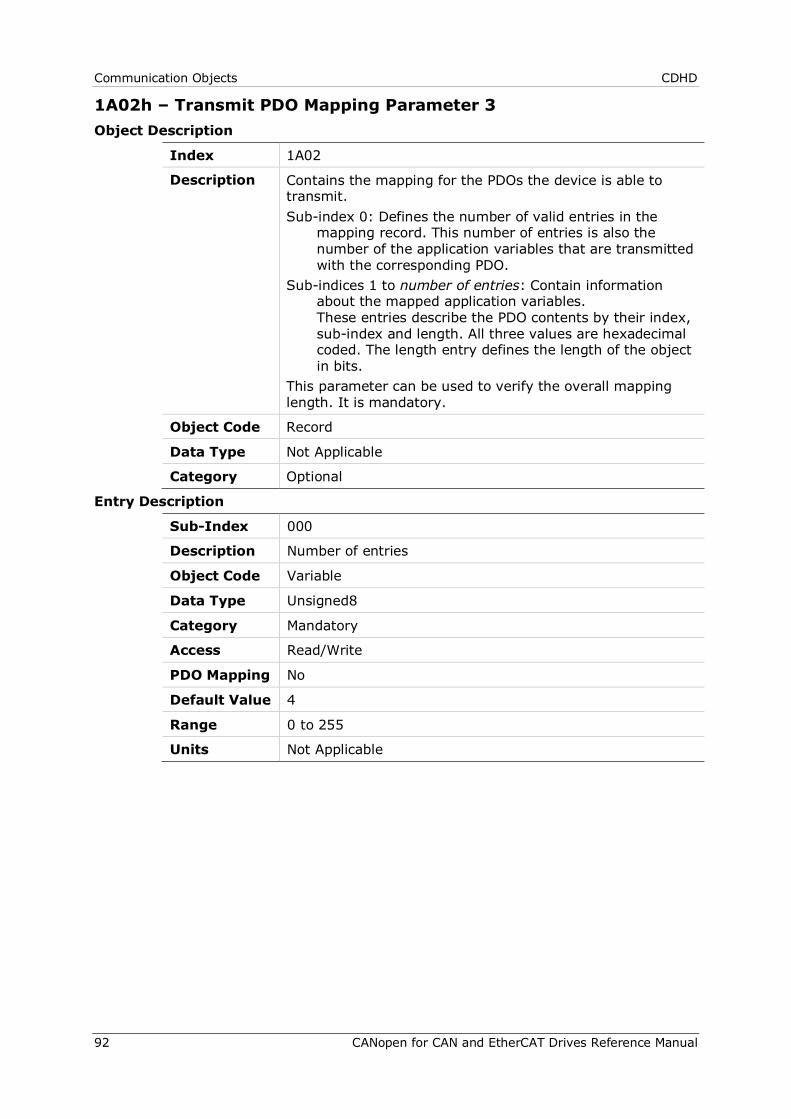
Communication Objects CDHD
92 CANopen for CAN and EtherCAT Drives Reference Manual
1A02h – Transmit PDO Mapping Parameter 3 Object Description
Index 1A02
Description Contains the mapping for the PDOs the device is able to transmit. Sub-index 0: Defines the number of valid entries in the
mapping record. This number of entries is also the number of the application variables that are transmitted with the corresponding PDO.
Sub-indices 1 to number of entries: Contain information about the mapped application variables. These entries describe the PDO contents by their index, sub-index and length. All three values are hexadecimal coded. The length entry defines the length of the object in bits.
This parameter can be used to verify the overall mapping length. It is mandatory.
Object Code Record
Data Type Not Applicable
Category Optional
Entry Description
Sub-Index 000
Description Number of entries
Object Code Variable
Data Type Unsigned8
Category Mandatory
Access Read/Write
PDO Mapping No
Default Value 4
Range 0 to 255
Units Not Applicable

CDHD Communication Objects
CANopen for CAN and EtherCAT Drives Reference Manual 93
Sub-Index 001
Description Mapping entry 1
Object Code Variable
Data Type Unsigned32
Category Optional
Access Read/Write
PDO Mapping No
Default Value 1618477072
Range 0 to 4294967295
Units Not Applicable
Sub-Index 002
Description Mapping entry 2
Object Code Variable
Data Type Unsigned32
Category Optional
Access Read/Write
PDO Mapping No
Default Value 1618214928
Range 0 to 4294967295
Units Not Applicable
Sub-Index 003
Description Mapping Entry 3
Object Code Variable
Data Type Unsigned32
Category Optional
Access Read/Write
PDO Mapping No
Default Value 552730640
Range 0 to 4294967295
Units Not Applicable
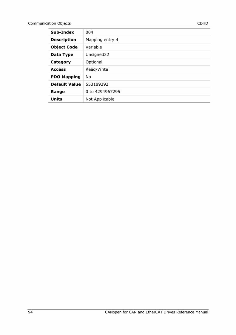
Communication Objects CDHD
94 CANopen for CAN and EtherCAT Drives Reference Manual
Sub-Index 004
Description Mapping entry 4
Object Code Variable
Data Type Unsigned32
Category Optional
Access Read/Write
PDO Mapping No
Default Value 553189392
Range 0 to 4294967295
Units Not Applicable
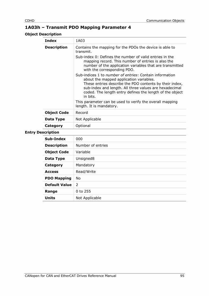
CDHD Communication Objects
CANopen for CAN and EtherCAT Drives Reference Manual 95
1A03h – Transmit PDO Mapping Parameter 4 Object Description
Index 1A03
Description Contains the mapping for the PDOs the device is able to transmit. Sub-index 0: Defines the number of valid entries in the
mapping record. This number of entries is also the number of the application variables that are transmitted with the corresponding PDO.
Sub-indices 1 to number of entries: Contain information about the mapped application variables. These entries describe the PDO contents by their index, sub-index and length. All three values are hexadecimal coded. The length entry defines the length of the object in bits.
This parameter can be used to verify the overall mapping length. It is mandatory.
Object Code Record
Data Type Not Applicable
Category Optional
Entry Description
Sub-Index 000
Description Number of entries
Object Code Variable
Data Type Unsigned8
Category Mandatory
Access Read/Write
PDO Mapping No
Default Value 2
Range 0 to 255
Units Not Applicable

Communication Objects CDHD
96 CANopen for CAN and EtherCAT Drives Reference Manual
Sub-Index 001
Description Mapping entry 1
Object Code Variable
Data Type Unsigned32
Category Optional
Access Read/Write
PDO Mapping No
Default Value 1627193376
Range 0 to 4294967295
Units Not Applicable
Sub-Index 002
Description Mapping entry 2
Object Code Variable
Data Type Unsigned32
Category Optional
Access Read/Write
PDO Mapping No
Default Value 548798496
Range 0 to 4294967295
Units Not Applicable
Sub-Index 003
Description Mapping entry 3
Object Code Variable
Data Type Unsigned32
Category Optional
Access Read/Write
PDO Mapping No
Default Value 0
Range 0 to 4294967295
Units Not Applicable

CDHD Communication Objects
CANopen for CAN and EtherCAT Drives Reference Manual 97
Sub-Index 004
Description Mapping entry 4
Object Code Variable
Data Type Unsigned32
Category Optional
Access Read/Write
PDO Mapping No
Default Value 0
Range 0 to 4294967295
Units Not Applicable
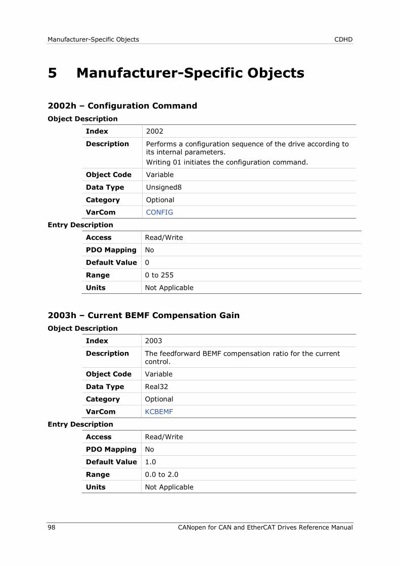
Manufacturer-Specific Objects CDHD
98 CANopen for CAN and EtherCAT Drives Reference Manual
5 Manufacturer-Specific Objects
2002h – Configuration Command Object Description
Index 2002
Description Performs a configuration sequence of the drive according to its internal parameters. Writing 01 initiates the configuration command.
Object Code Variable
Data Type Unsigned8
Category Optional
VarCom CONFIG
Entry Description
Access Read/Write
PDO Mapping No
Default Value 0
Range 0 to 255
Units Not Applicable
2003h – Current BEMF Compensation Gain Object Description
Index 2003
Description The feedforward BEMF compensation ratio for the current control.
Object Code Variable
Data Type Real32
Category Optional
VarCom KCBEMF
Entry Description
Access Read/Write
PDO Mapping No
Default Value 1.0
Range 0.0 to 2.0
Units Not Applicable

CDHD Manufacturer-Specific Objects
CANopen for CAN and EtherCAT Drives Reference Manual 99
2004h – Current DQ Axis Compensation Object Description
Index 2004
Description Current DQ axis compensation
Object Code Variable
Data Type Real32
Category Optional
VarCom KCDQCOMP
Entry Description
Access Read/Write
PDO Mapping No
Default Value 1.0
Range 0.0 to 1.0
Units Not Applicable
2006h – Current Integral (KI) Gain Object Description
Index 2006
Description The current controller integral gain.
Object Code Variable
Data Type Real32
Category Optional
VarCom KCI
Entry Description
Access Read/Write
PDO Mapping No
Default Value 1.0
Range 0.0 to 100.0
Units Not Applicable
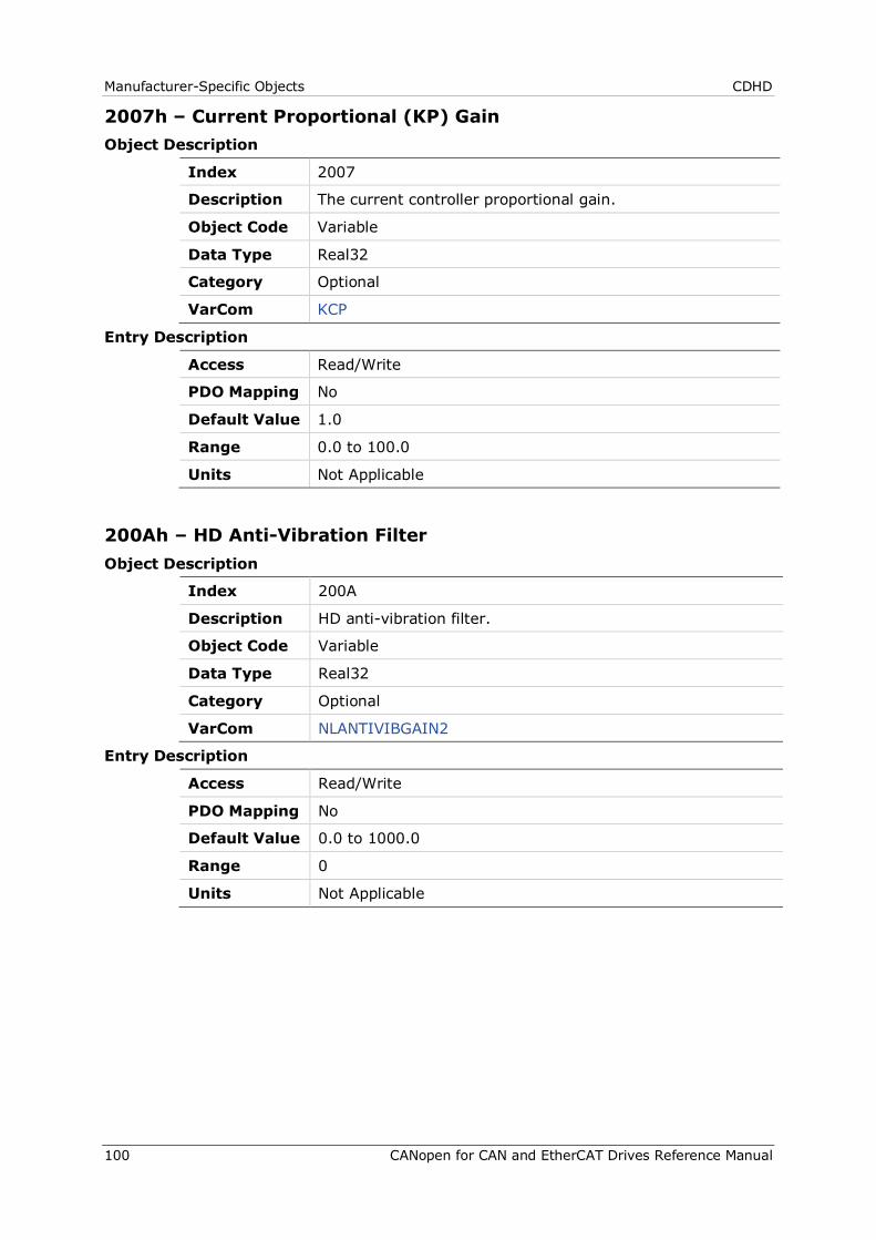
Manufacturer-Specific Objects CDHD
100 CANopen for CAN and EtherCAT Drives Reference Manual
2007h – Current Proportional (KP) Gain Object Description
Index 2007
Description The current controller proportional gain.
Object Code Variable
Data Type Real32
Category Optional
VarCom KCP
Entry Description
Access Read/Write
PDO Mapping No
Default Value 1.0
Range 0.0 to 100.0
Units Not Applicable
200Ah – HD Anti-Vibration Filter Object Description
Index 200A
Description HD anti-vibration filter.
Object Code Variable
Data Type Real32
Category Optional
VarCom NLANTIVIBGAIN2
Entry Description
Access Read/Write
PDO Mapping No
Default Value 0.0 to 1000.0
Range 0
Units Not Applicable
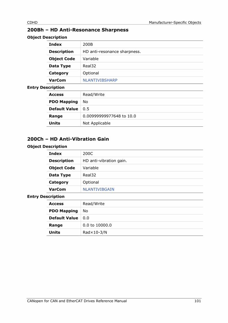
CDHD Manufacturer-Specific Objects
CANopen for CAN and EtherCAT Drives Reference Manual 101
200Bh – HD Anti-Resonance Sharpness Object Description
Index 200B
Description HD anti-resonance sharpness.
Object Code Variable
Data Type Real32
Category Optional
VarCom NLANTIVIBSHARP
Entry Description
Access Read/Write
PDO Mapping No
Default Value 0.5
Range 0.00999999977648 to 10.0
Units Not Applicable
200Ch – HD Anti-Vibration Gain Object Description
Index 200C
Description HD anti-vibration gain.
Object Code Variable
Data Type Real32
Category Optional
VarCom NLANTIVIBGAIN
Entry Description
Access Read/Write
PDO Mapping No
Default Value 0.0
Range 0.0 to 10000.0
Units Rad×10-3/N
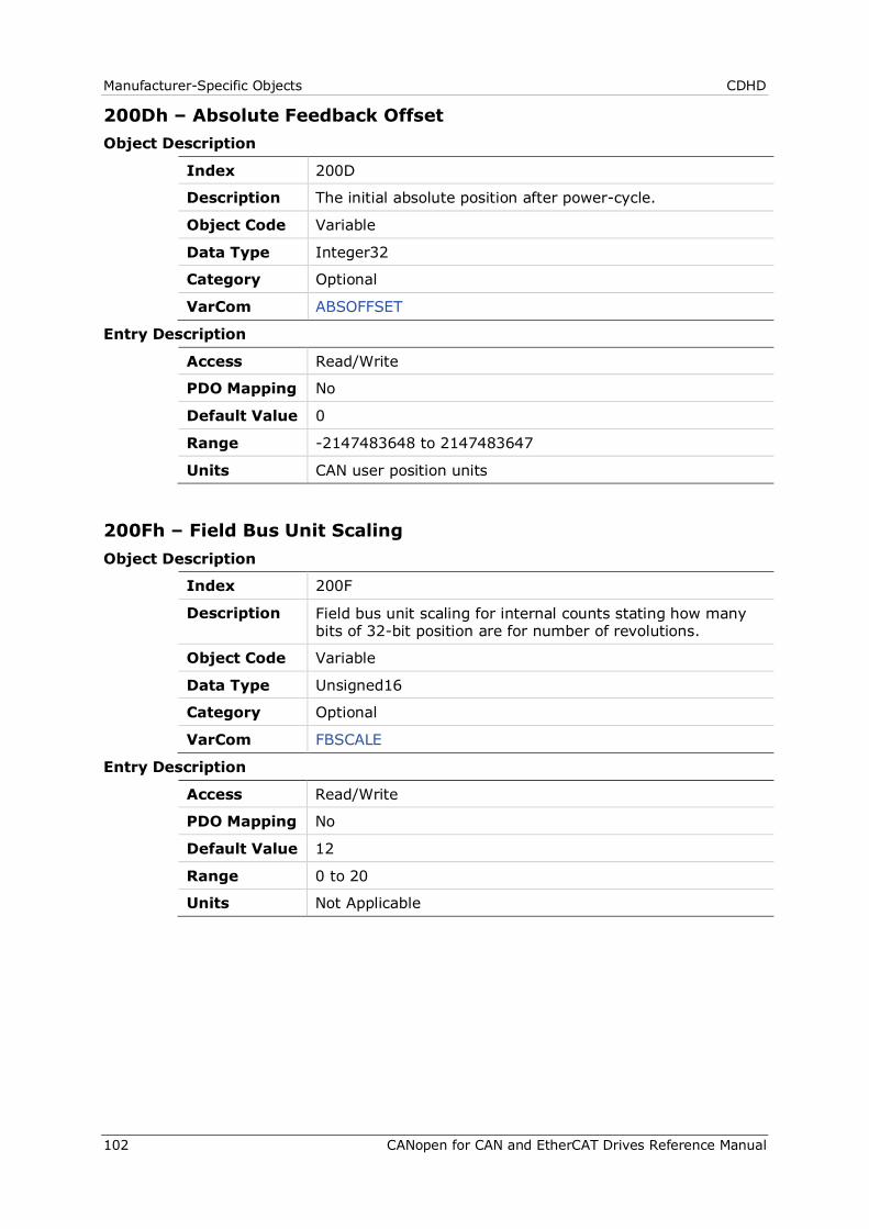
Manufacturer-Specific Objects CDHD
102 CANopen for CAN and EtherCAT Drives Reference Manual
200Dh – Absolute Feedback Offset Object Description
Index 200D
Description The initial absolute position after power-cycle.
Object Code Variable
Data Type Integer32
Category Optional
VarCom ABSOFFSET
Entry Description
Access Read/Write
PDO Mapping No
Default Value 0
Range -2147483648 to 2147483647
Units CAN user position units
200Fh – Field Bus Unit Scaling Object Description
Index 200F
Description Field bus unit scaling for internal counts stating how many bits of 32-bit position are for number of revolutions.
Object Code Variable
Data Type Unsigned16
Category Optional
VarCom FBSCALE
Entry Description
Access Read/Write
PDO Mapping No
Default Value 12
Range 0 to 20
Units Not Applicable
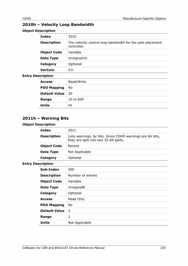
CDHD Manufacturer-Specific Objects
CANopen for CAN and EtherCAT Drives Reference Manual 103
2010h – Velocity Loop Bandwidth Object Description
Index 2010
Description The velocity control loop bandwidth for the pole placement controller.
Object Code Variable
Data Type Unsigned16
Category Optional
VarCom BW
Entry Description
Access Read/Write
PDO Mapping No
Default Value 30
Range 10 to 600
Units Hz
2011h – Warning Bits Object Description
Index 2011
Description Lists warnings, by bits. Since CDHD warnings are 64 bits, they are split into two 32-bit parts.
Object Code Record
Data Type Not Applicable
Category Optional
Entry Description
Sub-Index 000
Description Number of entries
Object Code Variable
Data Type Unsigned8
Category Optional
Access Read Only
PDO Mapping No
Default Value 2
Range 2
Units Not Applicable
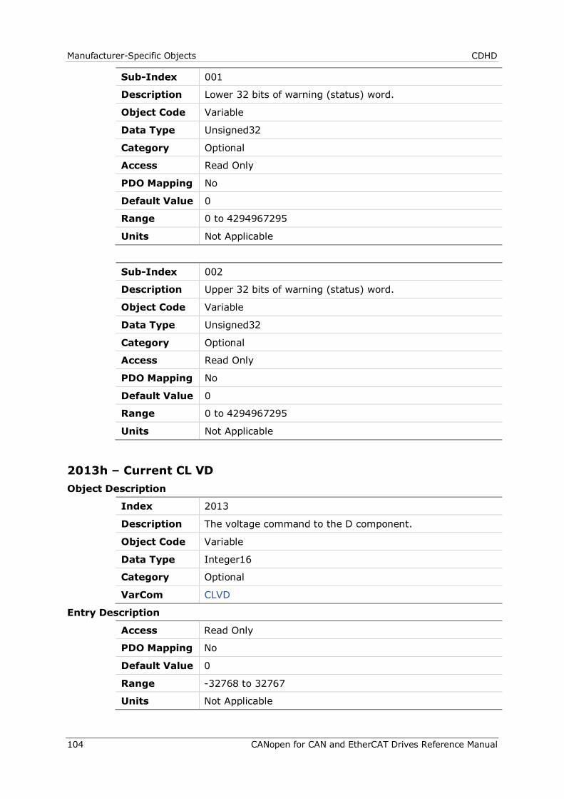
Manufacturer-Specific Objects CDHD
104 CANopen for CAN and EtherCAT Drives Reference Manual
Sub-Index 001
Description Lower 32 bits of warning (status) word.
Object Code Variable
Data Type Unsigned32
Category Optional
Access Read Only
PDO Mapping No
Default Value 0
Range 0 to 4294967295
Units Not Applicable
Sub-Index 002
Description Upper 32 bits of warning (status) word.
Object Code Variable
Data Type Unsigned32
Category Optional
Access Read Only
PDO Mapping No
Default Value 0
Range 0 to 4294967295
Units Not Applicable
2013h – Current CL VD Object Description
Index 2013
Description The voltage command to the D component.
Object Code Variable
Data Type Integer16
Category Optional
VarCom CLVD
Entry Description
Access Read Only
PDO Mapping No
Default Value 0
Range -32768 to 32767
Units Not Applicable
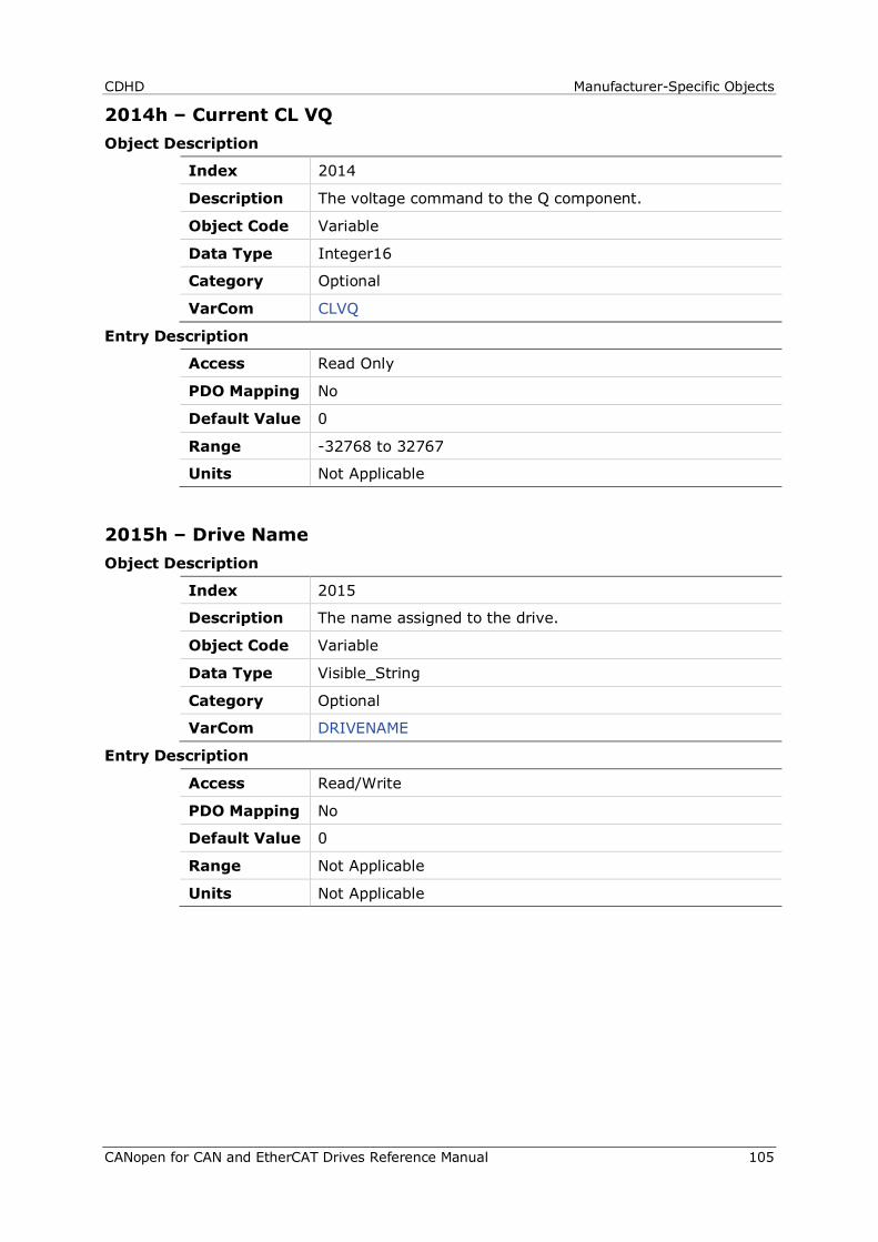
CDHD Manufacturer-Specific Objects
CANopen for CAN and EtherCAT Drives Reference Manual 105
2014h – Current CL VQ Object Description
Index 2014
Description The voltage command to the Q component.
Object Code Variable
Data Type Integer16
Category Optional
VarCom CLVQ
Entry Description
Access Read Only
PDO Mapping No
Default Value 0
Range -32768 to 32767
Units Not Applicable
2015h – Drive Name Object Description
Index 2015
Description The name assigned to the drive.
Object Code Variable
Data Type Visible_String
Category Optional
VarCom DRIVENAME
Entry Description
Access Read/Write
PDO Mapping No
Default Value 0
Range Not Applicable
Units Not Applicable
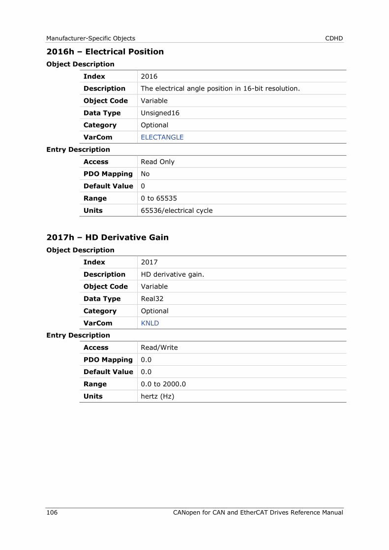
Manufacturer-Specific Objects CDHD
106 CANopen for CAN and EtherCAT Drives Reference Manual
2016h – Electrical Position Object Description
Index 2016
Description The electrical angle position in 16-bit resolution.
Object Code Variable
Data Type Unsigned16
Category Optional
VarCom ELECTANGLE
Entry Description
Access Read Only
PDO Mapping No
Default Value 0
Range 0 to 65535
Units 65536/electrical cycle
2017h – HD Derivative Gain Object Description
Index 2017
Description HD derivative gain.
Object Code Variable
Data Type Real32
Category Optional
VarCom KNLD
Entry Description
Access Read/Write
PDO Mapping 0.0
Default Value 0.0
Range 0.0 to 2000.0
Units hertz (Hz)
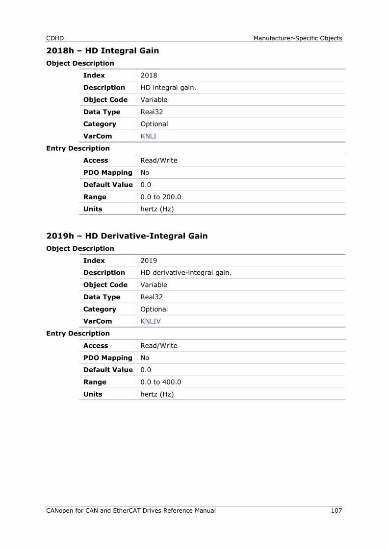
CDHD Manufacturer-Specific Objects
CANopen for CAN and EtherCAT Drives Reference Manual 107
2018h – HD Integral Gain Object Description
Index 2018
Description HD integral gain.
Object Code Variable
Data Type Real32
Category Optional
VarCom KNLI
Entry Description
Access Read/Write
PDO Mapping No
Default Value 0.0
Range 0.0 to 200.0
Units hertz (Hz)
2019h – HD Derivative-Integral Gain Object Description
Index 2019
Description HD derivative-integral gain.
Object Code Variable
Data Type Real32
Category Optional
VarCom KNLIV
Entry Description
Access Read/Write
PDO Mapping No
Default Value 0.0
Range 0.0 to 400.0
Units hertz (Hz)
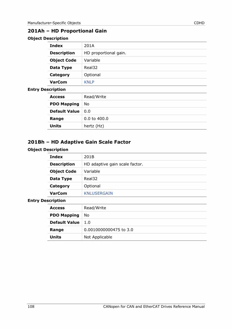
Manufacturer-Specific Objects CDHD
108 CANopen for CAN and EtherCAT Drives Reference Manual
201Ah – HD Proportional Gain Object Description
Index 201A
Description HD proportional gain.
Object Code Variable
Data Type Real32
Category Optional
VarCom KNLP
Entry Description
Access Read/Write
PDO Mapping No
Default Value 0.0
Range 0.0 to 400.0
Units hertz (Hz)
201Bh – HD Adaptive Gain Scale Factor Object Description
Index 201B
Description HD adaptive gain scale factor.
Object Code Variable
Data Type Real32
Category Optional
VarCom KNLUSERGAIN
Entry Description
Access Read/Write
PDO Mapping No
Default Value 1.0
Range 0.0010000000475 to 3.0
Units Not Applicable
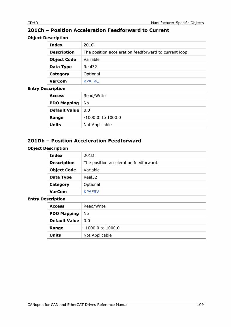
CDHD Manufacturer-Specific Objects
CANopen for CAN and EtherCAT Drives Reference Manual 109
201Ch – Position Acceleration Feedforward to Current Object Description
Index 201C
Description The position acceleration feedforward to current loop.
Object Code Variable
Data Type Real32
Category Optional
VarCom KPAFRC
Entry Description
Access Read/Write
PDO Mapping No
Default Value 0.0
Range -1000.0. to 1000.0
Units Not Applicable
201Dh – Position Acceleration Feedforward Object Description
Index 201D
Description The position acceleration feedforward.
Object Code Variable
Data Type Real32
Category Optional
VarCom KPAFRV
Entry Description
Access Read/Write
PDO Mapping No
Default Value 0.0
Range -1000.0 to 1000.0
Units Not Applicable
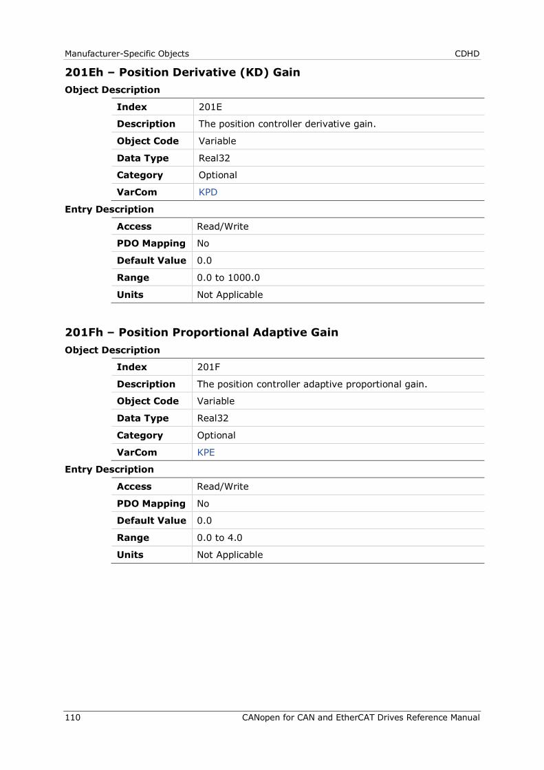
Manufacturer-Specific Objects CDHD
110 CANopen for CAN and EtherCAT Drives Reference Manual
201Eh – Position Derivative (KD) Gain Object Description
Index 201E
Description The position controller derivative gain.
Object Code Variable
Data Type Real32
Category Optional
VarCom KPD
Entry Description
Access Read/Write
PDO Mapping No
Default Value 0.0
Range 0.0 to 1000.0
Units Not Applicable
201Fh – Position Proportional Adaptive Gain Object Description
Index 201F
Description The position controller adaptive proportional gain.
Object Code Variable
Data Type Real32
Category Optional
VarCom KPE
Entry Description
Access Read/Write
PDO Mapping No
Default Value 0.0
Range 0.0 to 4.0
Units Not Applicable
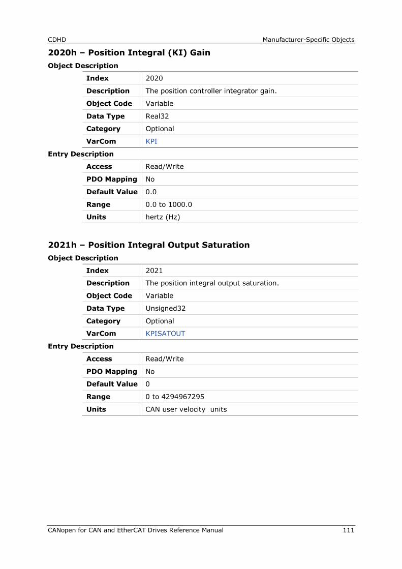
CDHD Manufacturer-Specific Objects
CANopen for CAN and EtherCAT Drives Reference Manual 111
2020h – Position Integral (KI) Gain Object Description
Index 2020
Description The position controller integrator gain.
Object Code Variable
Data Type Real32
Category Optional
VarCom KPI
Entry Description
Access Read/Write
PDO Mapping No
Default Value 0.0
Range 0.0 to 1000.0
Units hertz (Hz)
2021h – Position Integral Output Saturation Object Description
Index 2021
Description The position integral output saturation.
Object Code Variable
Data Type Unsigned32
Category Optional
VarCom KPISATOUT
Entry Description
Access Read/Write
PDO Mapping No
Default Value 0
Range 0 to 4294967295
Units CAN user velocity units
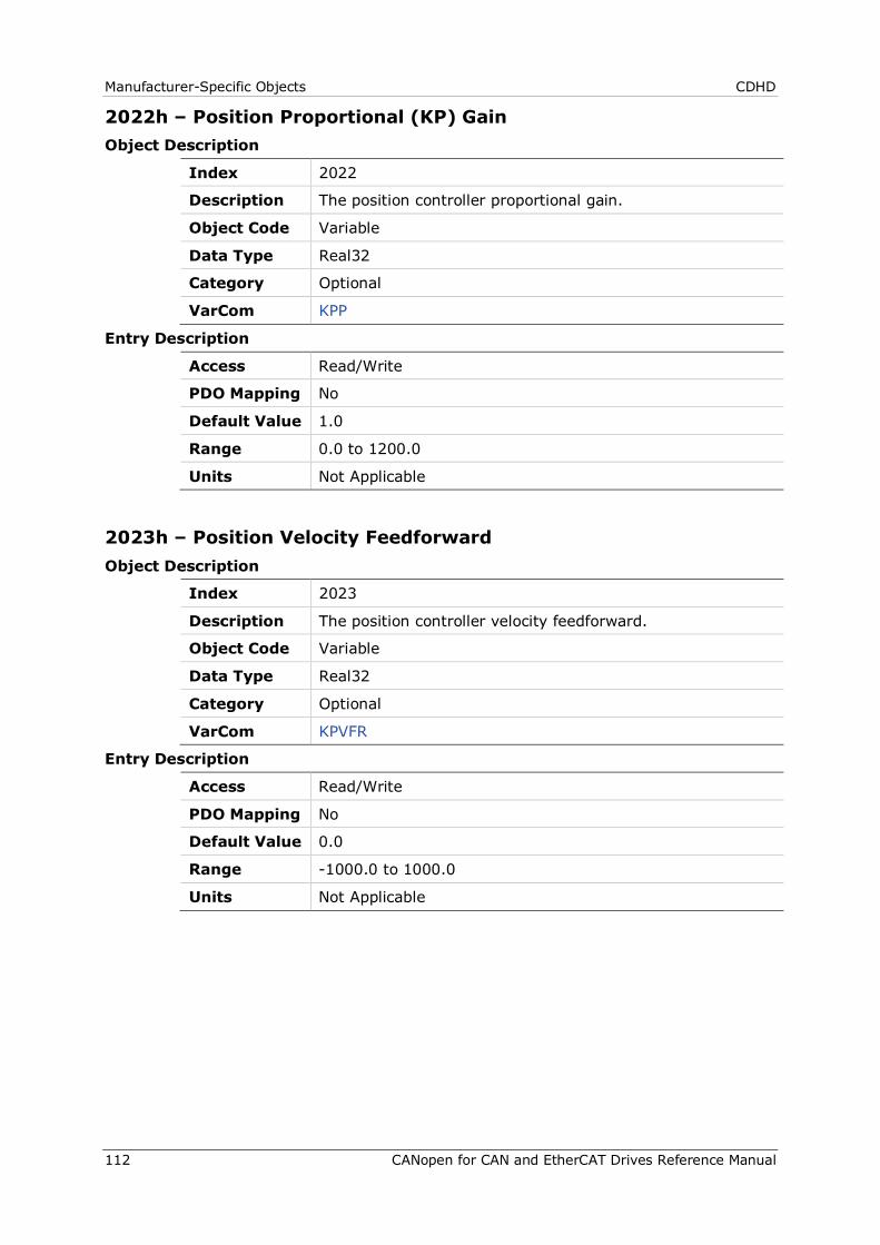
Manufacturer-Specific Objects CDHD
112 CANopen for CAN and EtherCAT Drives Reference Manual
2022h – Position Proportional (KP) Gain Object Description
Index 2022
Description The position controller proportional gain.
Object Code Variable
Data Type Real32
Category Optional
VarCom KPP
Entry Description
Access Read/Write
PDO Mapping No
Default Value 1.0
Range 0.0 to 1200.0
Units Not Applicable
2023h – Position Velocity Feedforward Object Description
Index 2023
Description The position controller velocity feedforward.
Object Code Variable
Data Type Real32
Category Optional
VarCom KPVFR
Entry Description
Access Read/Write
PDO Mapping No
Default Value 0.0
Range -1000.0 to 1000.0
Units Not Applicable
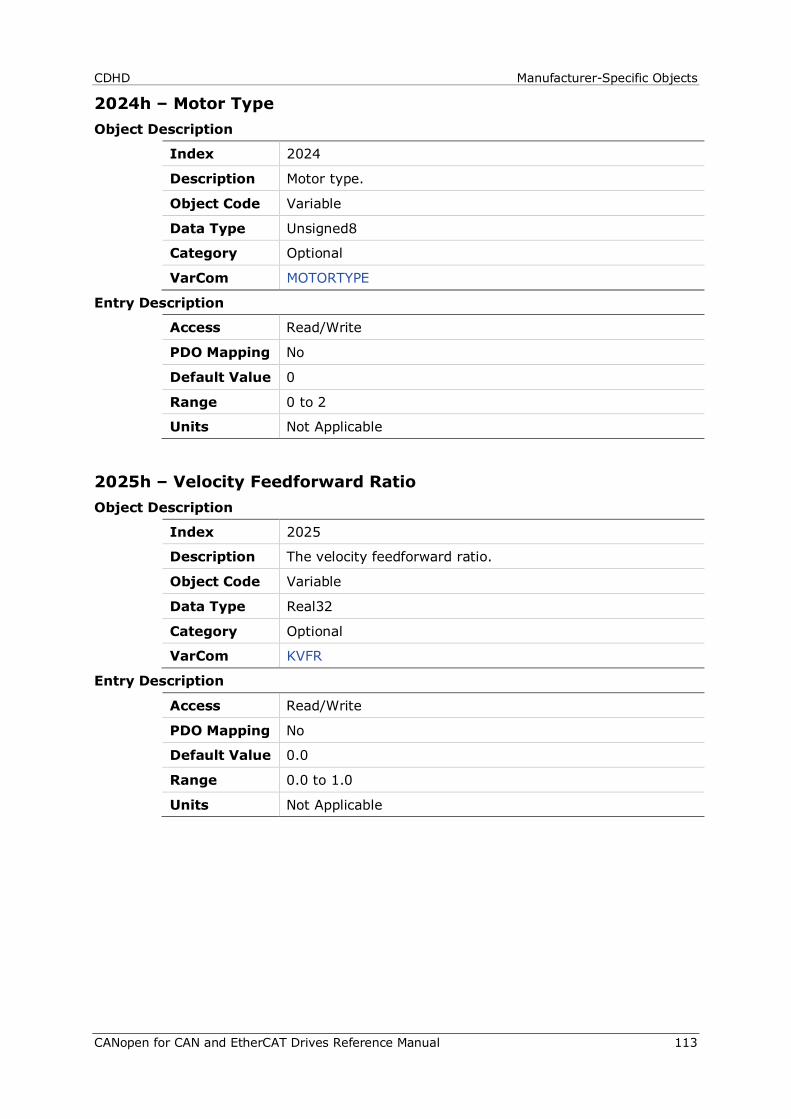
CDHD Manufacturer-Specific Objects
CANopen for CAN and EtherCAT Drives Reference Manual 113
2024h – Motor Type Object Description
Index 2024
Description Motor type.
Object Code Variable
Data Type Unsigned8
Category Optional
VarCom MOTORTYPE
Entry Description
Access Read/Write
PDO Mapping No
Default Value 0
Range 0 to 2
Units Not Applicable
2025h – Velocity Feedforward Ratio Object Description
Index 2025
Description The velocity feedforward ratio.
Object Code Variable
Data Type Real32
Category Optional
VarCom KVFR
Entry Description
Access Read/Write
PDO Mapping No
Default Value 0.0
Range 0.0 to 1.0
Units Not Applicable
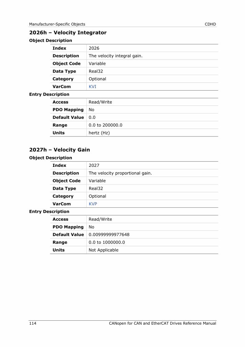
Manufacturer-Specific Objects CDHD
114 CANopen for CAN and EtherCAT Drives Reference Manual
2026h – Velocity Integrator Object Description
Index 2026
Description The velocity integral gain.
Object Code Variable
Data Type Real32
Category Optional
VarCom KVI
Entry Description
Access Read/Write
PDO Mapping No
Default Value 0.0
Range 0.0 to 200000.0
Units hertz (Hz)
2027h – Velocity Gain Object Description
Index 2027
Description The velocity proportional gain.
Object Code Variable
Data Type Real32
Category Optional
VarCom KVP
Entry Description
Access Read/Write
PDO Mapping No
Default Value 0.00999999977648
Range 0.0 to 1000000.0
Units Not Applicable
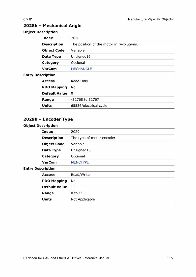
CDHD Manufacturer-Specific Objects
CANopen for CAN and EtherCAT Drives Reference Manual 115
2028h – Mechanical Angle Object Description
Index 2028
Description The position of the motor in revolutions.
Object Code Variable
Data Type Unsigned16
Category Optional
VarCom MECHANGLE
Entry Description
Access Read Only
PDO Mapping No
Default Value 0
Range -32768 to 32767
Units 65536/electrical cycle
2029h – Encoder Type Object Description
Index 2029
Description The type of motor encoder
Object Code Variable
Data Type Unsigned16
Category Optional
VarCom MENCTYPE
Entry Description
Access Read/Write
PDO Mapping No
Default Value 11
Range 0 to 11
Units Not Applicable
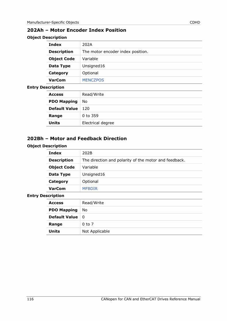
Manufacturer-Specific Objects CDHD
116 CANopen for CAN and EtherCAT Drives Reference Manual
202Ah – Motor Encoder Index Position Object Description
Index 202A
Description The motor encoder index position.
Object Code Variable
Data Type Unsigned16
Category Optional
VarCom MENCZPOS
Entry Description
Access Read/Write
PDO Mapping No
Default Value 120
Range 0 to 359
Units Electrical degree
202Bh – Motor and Feedback Direction Object Description
Index 202B
Description The direction and polarity of the motor and feedback.
Object Code Variable
Data Type Unsigned16
Category Optional
VarCom MFBDIR
Entry Description
Access Read/Write
PDO Mapping No
Default Value 0
Range 0 to 7
Units Not Applicable
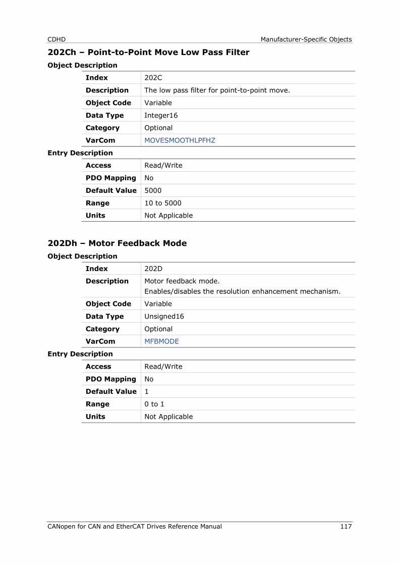
CDHD Manufacturer-Specific Objects
CANopen for CAN and EtherCAT Drives Reference Manual 117
202Ch – Point-to-Point Move Low Pass Filter Object Description
Index 202C
Description The low pass filter for point-to-point move.
Object Code Variable
Data Type Integer16
Category Optional
VarCom MOVESMOOTHLPFHZ
Entry Description
Access Read/Write
PDO Mapping No
Default Value 5000
Range 10 to 5000
Units Not Applicable
202Dh – Motor Feedback Mode Object Description
Index 202D
Description Motor feedback mode. Enables/disables the resolution enhancement mechanism.
Object Code Variable
Data Type Unsigned16
Category Optional
VarCom MFBMODE
Entry Description
Access Read/Write
PDO Mapping No
Default Value 1
Range 0 to 1
Units Not Applicable
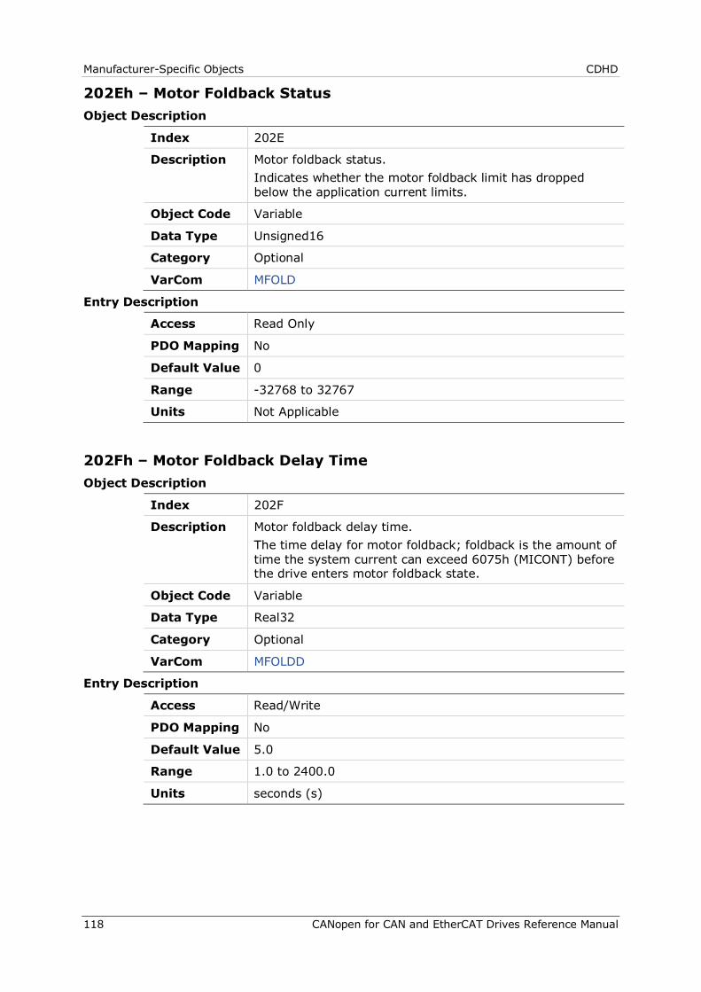
Manufacturer-Specific Objects CDHD
118 CANopen for CAN and EtherCAT Drives Reference Manual
202Eh – Motor Foldback Status Object Description
Index 202E
Description Motor foldback status. Indicates whether the motor foldback limit has dropped below the application current limits.
Object Code Variable
Data Type Unsigned16
Category Optional
VarCom MFOLD
Entry Description
Access Read Only
PDO Mapping No
Default Value 0
Range -32768 to 32767
Units Not Applicable
202Fh – Motor Foldback Delay Time Object Description
Index 202F
Description Motor foldback delay time. The time delay for motor foldback; foldback is the amount of time the system current can exceed 6075h (MICONT) before the drive enters motor foldback state.
Object Code Variable
Data Type Real32
Category Optional
VarCom MFOLDD
Entry Description
Access Read/Write
PDO Mapping No
Default Value 5.0
Range 1.0 to 2400.0
Units seconds (s)
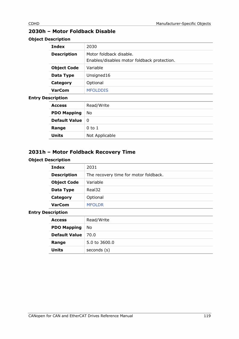
CDHD Manufacturer-Specific Objects
CANopen for CAN and EtherCAT Drives Reference Manual 119
2030h – Motor Foldback Disable Object Description
Index 2030
Description Motor foldback disable. Enables/disables motor foldback protection.
Object Code Variable
Data Type Unsigned16
Category Optional
VarCom MFOLDDIS
Entry Description
Access Read/Write
PDO Mapping No
Default Value 0
Range 0 to 1
Units Not Applicable
2031h – Motor Foldback Recovery Time Object Description
Index 2031
Description The recovery time for motor foldback.
Object Code Variable
Data Type Real32
Category Optional
VarCom MFOLDR
Entry Description
Access Read/Write
PDO Mapping No
Default Value 70.0
Range 5.0 to 3600.0
Units seconds (s)

Manufacturer-Specific Objects CDHD
120 CANopen for CAN and EtherCAT Drives Reference Manual
2032h – Motor Foldback Time Constant Object Description
Index 2032
Description The time constant for motor foldback.
Object Code Variable
Data Type Real32
Category Optional
VarCom MFOLDT
Entry Description
Access Read/Write
PDO Mapping No
Default Value 5.0
Range 1.0 to 1200.0
Units seconds (s)
2033h – Motor Foldback Current Object Description
Index 2033
Description The current limit derived from the motor foldback mechanism. Foldback condition occurs when 2033h (MIFOLD) goes below 6072h (ILIM).
Object Code Variable
Data Type Unsigned32
Category Optional
VarCom MIFOLD
Entry Description
Access Read Only
PDO Mapping No
Default Value 0
Range 0 to 4294967295
Units mA

CDHD Manufacturer-Specific Objects
CANopen for CAN and EtherCAT Drives Reference Manual 121
2034h – Motor Foldback Fault Threshold Object Description
Index 2034
Description The motor foldback fault threshold.
Object Code Variable
Data Type Unsigned32
Category Optional
VarCom MIFOLDFTHRESH
Entry Description
Access Read/Write
PDO Mapping No
Default Value 0
Range 0 to 4294967295
Units mA
2035h – Motor Foldback Warning Threshold Object Description
Index 2035
Description The motor foldback fault warning threshold.
Object Code Variable
Data Type Unsigned32
Category Optional
VarCom MIFOLDWTHRESH
Entry Description
Access Read/Write
PDO Mapping No
Default Value 0
Range 0 to 4294967295
Units mA
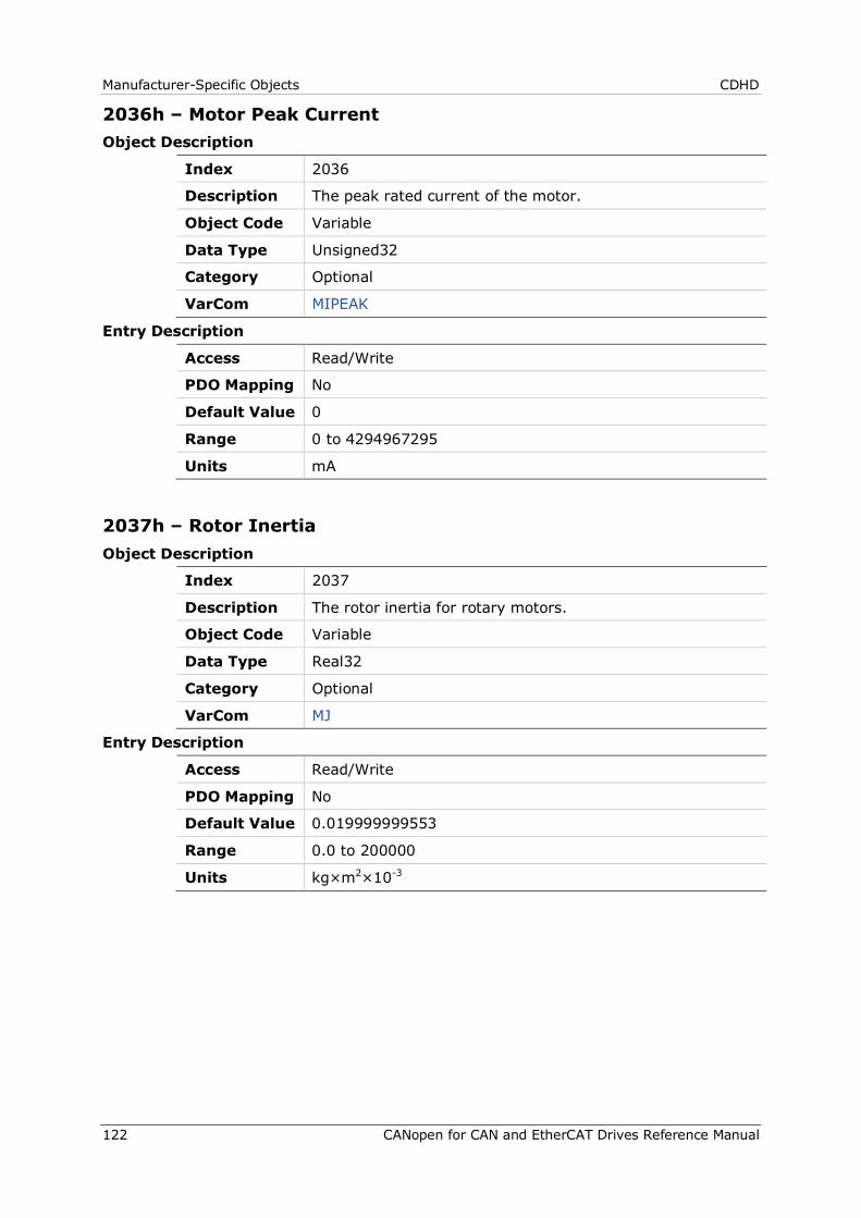
Manufacturer-Specific Objects CDHD
122 CANopen for CAN and EtherCAT Drives Reference Manual
2036h – Motor Peak Current Object Description
Index 2036
Description The peak rated current of the motor.
Object Code Variable
Data Type Unsigned32
Category Optional
VarCom MIPEAK
Entry Description
Access Read/Write
PDO Mapping No
Default Value 0
Range 0 to 4294967295
Units mA
2037h – Rotor Inertia Object Description
Index 2037
Description The rotor inertia for rotary motors.
Object Code Variable
Data Type Real32
Category Optional
VarCom MJ
Entry Description
Access Read/Write
PDO Mapping No
Default Value 0.019999999553
Range 0.0 to 200000
Units kg×m2×10-3
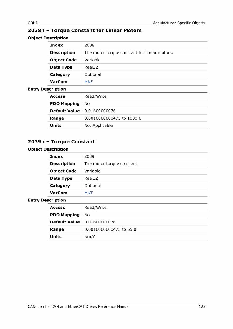
CDHD Manufacturer-Specific Objects
CANopen for CAN and EtherCAT Drives Reference Manual 123
2038h – Torque Constant for Linear Motors Object Description
Index 2038
Description The motor torque constant for linear motors.
Object Code Variable
Data Type Real32
Category Optional
VarCom MKF
Entry Description
Access Read/Write
PDO Mapping No
Default Value 0.01600000076
Range 0.0010000000475 to 1000.0
Units Not Applicable
2039h – Torque Constant Object Description
Index 2039
Description The motor torque constant.
Object Code Variable
Data Type Real32
Category Optional
VarCom MKT
Entry Description
Access Read/Write
PDO Mapping No
Default Value 0.01600000076
Range 0.0010000000475 to 65.0
Units Nm/A
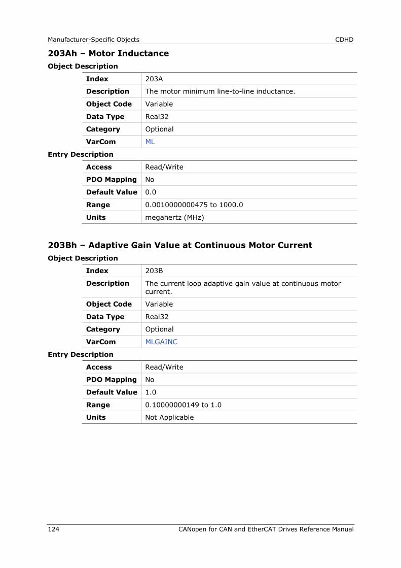
Manufacturer-Specific Objects CDHD
124 CANopen for CAN and EtherCAT Drives Reference Manual
203Ah – Motor Inductance Object Description
Index 203A
Description The motor minimum line-to-line inductance.
Object Code Variable
Data Type Real32
Category Optional
VarCom ML
Entry Description
Access Read/Write
PDO Mapping No
Default Value 0.0
Range 0.0010000000475 to 1000.0
Units megahertz (MHz)
203Bh – Adaptive Gain Value at Continuous Motor Current Object Description
Index 203B
Description The current loop adaptive gain value at continuous motor current.
Object Code Variable
Data Type Real32
Category Optional
VarCom MLGAINC
Entry Description
Access Read/Write
PDO Mapping No
Default Value 1.0
Range 0.10000000149 to 1.0
Units Not Applicable
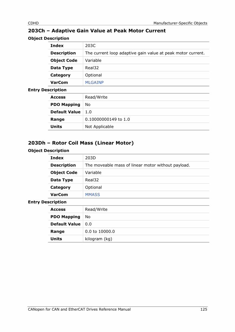
CDHD Manufacturer-Specific Objects
CANopen for CAN and EtherCAT Drives Reference Manual 125
203Ch – Adaptive Gain Value at Peak Motor Current Object Description
Index 203C
Description The current loop adaptive gain value at peak motor current.
Object Code Variable
Data Type Real32
Category Optional
VarCom MLGAINP
Entry Description
Access Read/Write
PDO Mapping No
Default Value 1.0
Range 0.10000000149 to 1.0
Units Not Applicable
203Dh – Rotor Coil Mass (Linear Motor) Object Description
Index 203D
Description The moveable mass of linear motor without payload.
Object Code Variable
Data Type Real32
Category Optional
VarCom MMASS
Entry Description
Access Read/Write
PDO Mapping No
Default Value 0.0
Range 0.0 to 10000.0
Units kilogram (kg)
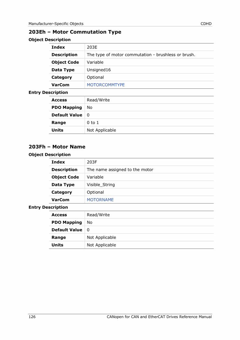
Manufacturer-Specific Objects CDHD
126 CANopen for CAN and EtherCAT Drives Reference Manual
203Eh – Motor Commutation Type Object Description
Index 203E
Description The type of motor commutation - brushless or brush.
Object Code Variable
Data Type Unsigned16
Category Optional
VarCom MOTORCOMMTYPE
Entry Description
Access Read/Write
PDO Mapping No
Default Value 0
Range 0 to 1
Units Not Applicable
203Fh – Motor Name Object Description
Index 203F
Description The name assigned to the motor
Object Code Variable
Data Type Visible_String
Category Optional
VarCom MOTORNAME
Entry Description
Access Read/Write
PDO Mapping No
Default Value 0
Range Not Applicable
Units Not Applicable
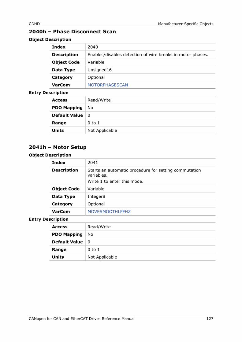
CDHD Manufacturer-Specific Objects
CANopen for CAN and EtherCAT Drives Reference Manual 127
2040h – Phase Disconnect Scan Object Description
Index 2040
Description Enables/disables detection of wire breaks in motor phases.
Object Code Variable
Data Type Unsigned16
Category Optional
VarCom MOTORPHASESCAN
Entry Description
Access Read/Write
PDO Mapping No
Default Value 0
Range 0 to 1
Units Not Applicable
2041h – Motor Setup Object Description
Index 2041
Description Starts an automatic procedure for setting commutation variables. Write 1 to enter this mode.
Object Code Variable
Data Type Integer8
Category Optional
VarCom MOVESMOOTHLPFHZ
Entry Description
Access Read/Write
PDO Mapping No
Default Value 0
Range 0 to 1
Units Not Applicable
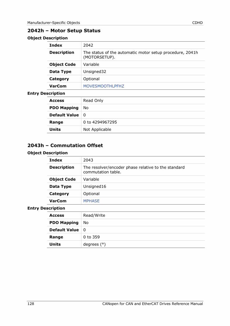
Manufacturer-Specific Objects CDHD
128 CANopen for CAN and EtherCAT Drives Reference Manual
2042h – Motor Setup Status Object Description
Index 2042
Description The status of the automatic motor setup procedure, 2041h (MOTORSETUP).
Object Code Variable
Data Type Unsigned32
Category Optional
VarCom MOVESMOOTHLPFHZ
Entry Description
Access Read Only
PDO Mapping No
Default Value 0
Range 0 to 4294967295
Units Not Applicable
2043h – Commutation Offset Object Description
Index 2043
Description The resolver/encoder phase relative to the standard commutation table.
Object Code Variable
Data Type Unsigned16
Category Optional
VarCom MPHASE
Entry Description
Access Read/Write
PDO Mapping No
Default Value 0
Range 0 to 359
Units degrees (°)
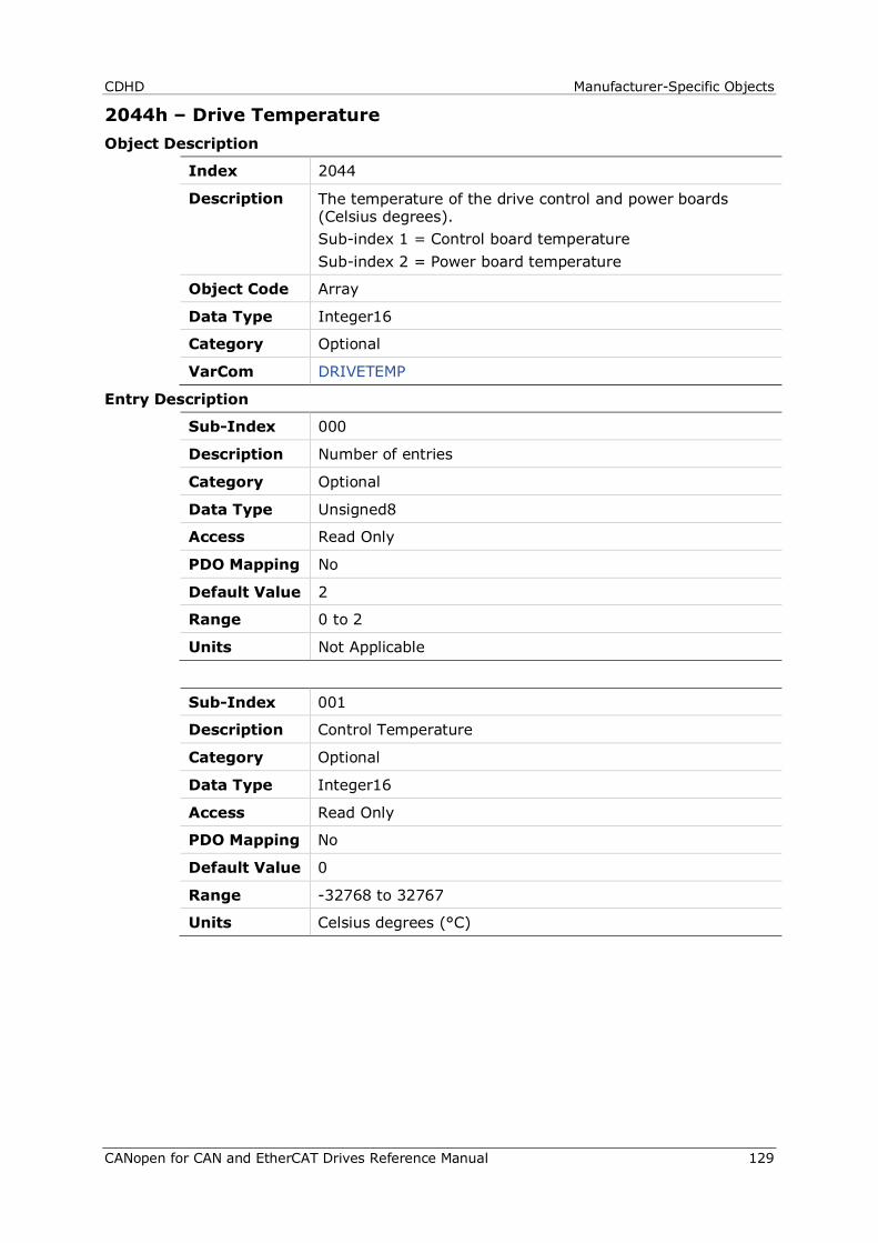
CDHD Manufacturer-Specific Objects
CANopen for CAN and EtherCAT Drives Reference Manual 129
2044h – Drive Temperature Object Description
Index 2044
Description The temperature of the drive control and power boards (Celsius degrees). Sub-index 1 = Control board temperature Sub-index 2 = Power board temperature
Object Code Array
Data Type Integer16
Category Optional
VarCom DRIVETEMP
Entry Description
Sub-Index 000
Description Number of entries
Category Optional
Data Type Unsigned8
Access Read Only
PDO Mapping No
Default Value 2
Range 0 to 2
Units Not Applicable
Sub-Index 001
Description Control Temperature
Category Optional
Data Type Integer16
Access Read Only
PDO Mapping No
Default Value 0
Range -32768 to 32767
Units Celsius degrees (°C)

Manufacturer-Specific Objects CDHD
130 CANopen for CAN and EtherCAT Drives Reference Manual
Sub-Index 002
Description Power Temperature
Category Optional
Data Type Integer16
Access Read Only
PDO Mapping No
Default Value 0
Range -32768 to 32767
Units Celsius degrees (°C)
2045h – Feedback Direction Object Description
Index 2045
Description Feedback positive direction.
Object Code Variable
Data Type Unsigned16
Category Optional
VarCom DIR
Entry Description
Access Read/Write
PDO Mapping No
Default Value 0
Range 0 to 1
Units Not Applicable
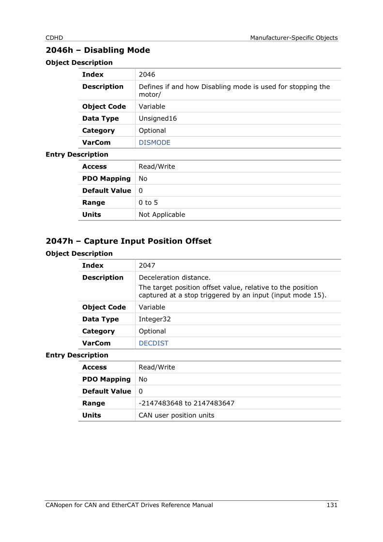
CDHD Manufacturer-Specific Objects
CANopen for CAN and EtherCAT Drives Reference Manual 131
2046h – Disabling Mode Object Description
Index 2046
Description Defines if and how Disabling mode is used for stopping the motor/
Object Code Variable
Data Type Unsigned16
Category Optional
VarCom DISMODE
Entry Description
Access Read/Write
PDO Mapping No
Default Value 0
Range 0 to 5
Units Not Applicable
2047h – Capture Input Position Offset Object Description
Index 2047
Description Deceleration distance. The target position offset value, relative to the position captured at a stop triggered by an input (input mode 15).
Object Code Variable
Data Type Integer32
Category Optional
VarCom DECDIST
Entry Description
Access Read/Write
PDO Mapping No
Default Value 0
Range -2147483648 to 2147483647
Units CAN user position units

Manufacturer-Specific Objects CDHD
132 CANopen for CAN and EtherCAT Drives Reference Manual
2048h – Capture Input Position Offset 2 Object Description
Index 2048
Description Deceleration distance 2. The target position offset value, relative to the position captured at a stop triggered by an input (input mode 16).
Object Code Variable
Data Type Integer32
Category Optional
VarCom DECDIST2
Entry Description
Access Read/Write
PDO Mapping No
Default Value 0
Range -2147483648 to 2147483647
Units CAN user position units
2049h – Quick Stop Deceleration Time Object Description
Index 2049
Description The deceleration time for an Active Disabling/emergency stop.
Object Code Variable
Data Type Unsigned16
Category Optional
VarCom DECSTOPTIME
Entry Description
Access Read/Write
PDO Mapping No
Default Value 0
Range 0 to 6500
Units milliseconds (ms)
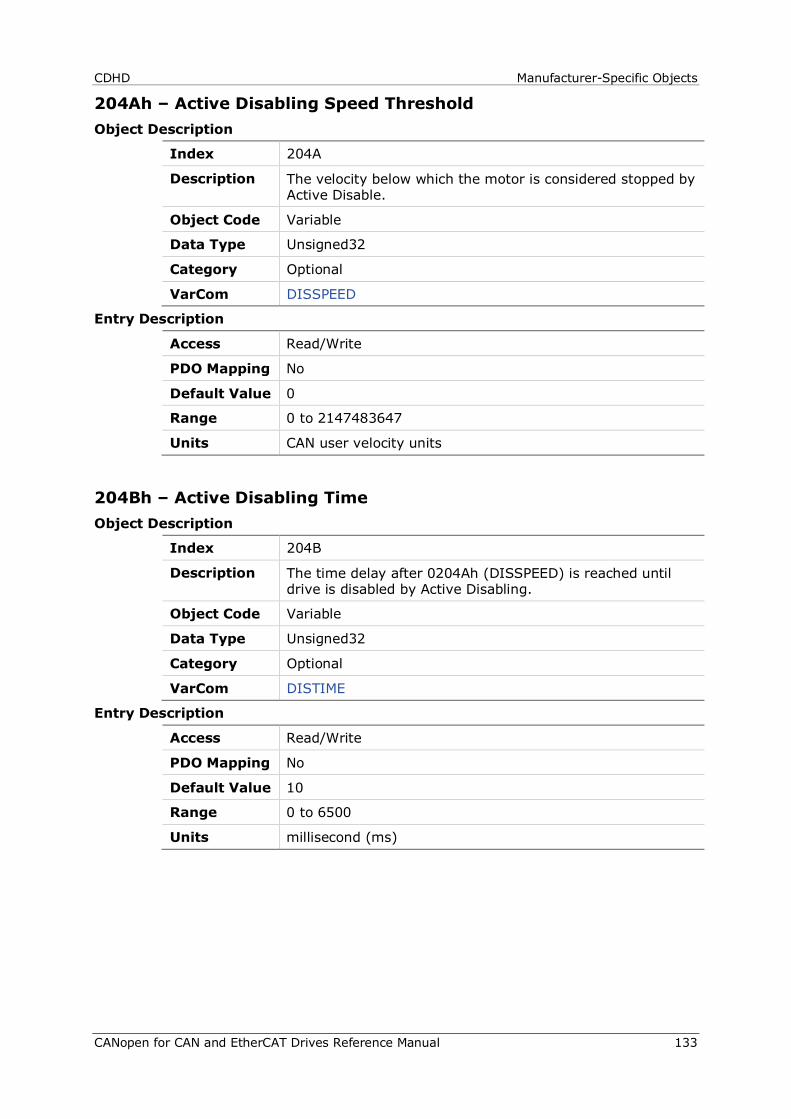
CDHD Manufacturer-Specific Objects
CANopen for CAN and EtherCAT Drives Reference Manual 133
204Ah – Active Disabling Speed Threshold Object Description
Index 204A
Description The velocity below which the motor is considered stopped by Active Disable.
Object Code Variable
Data Type Unsigned32
Category Optional
VarCom DISSPEED
Entry Description
Access Read/Write
PDO Mapping No
Default Value 0
Range 0 to 2147483647
Units CAN user velocity units
204Bh – Active Disabling Time Object Description
Index 204B
Description The time delay after 0204Ah (DISSPEED) is reached until drive is disabled by Active Disabling.
Object Code Variable
Data Type Unsigned32
Category Optional
VarCom DISTIME
Entry Description
Access Read/Write
PDO Mapping No
Default Value 10
Range 0 to 6500
Units millisecond (ms)
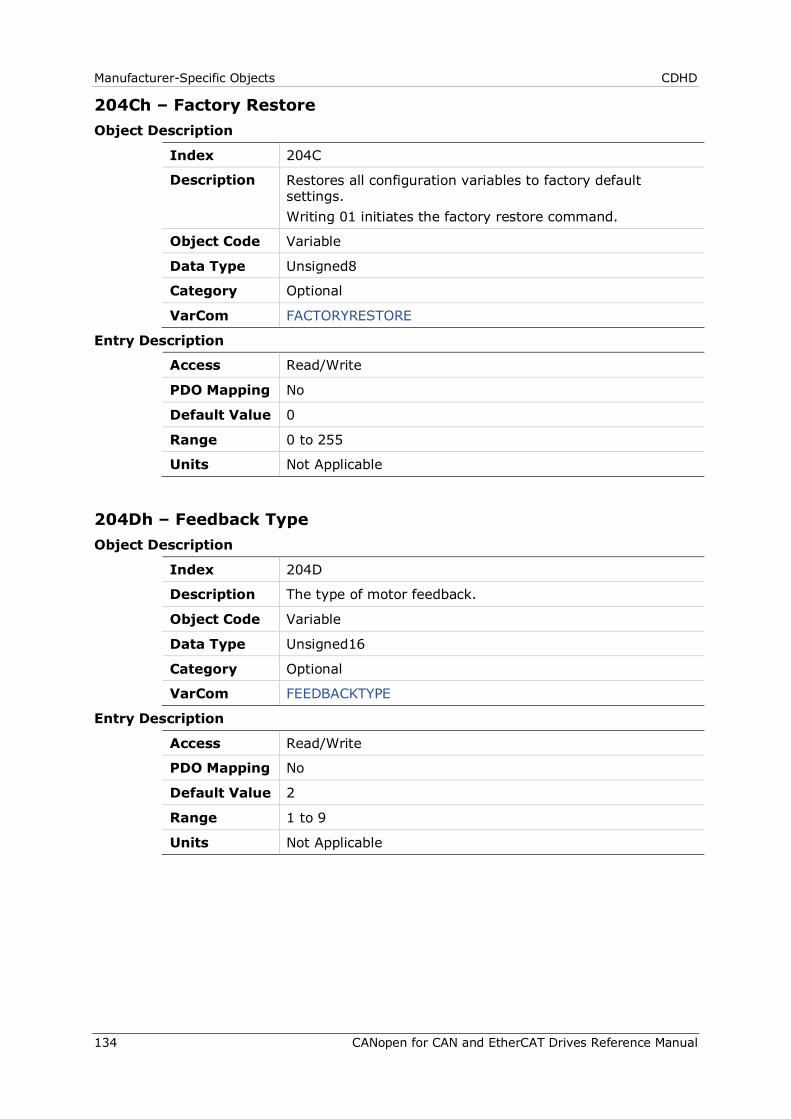
Manufacturer-Specific Objects CDHD
134 CANopen for CAN and EtherCAT Drives Reference Manual
204Ch – Factory Restore Object Description
Index 204C
Description Restores all configuration variables to factory default settings. Writing 01 initiates the factory restore command.
Object Code Variable
Data Type Unsigned8
Category Optional
VarCom FACTORYRESTORE
Entry Description
Access Read/Write
PDO Mapping No
Default Value 0
Range 0 to 255
Units Not Applicable
204Dh – Feedback Type Object Description
Index 204D
Description The type of motor feedback.
Object Code Variable
Data Type Unsigned16
Category Optional
VarCom FEEDBACKTYPE
Entry Description
Access Read/Write
PDO Mapping No
Default Value 2
Range 1 to 9
Units Not Applicable
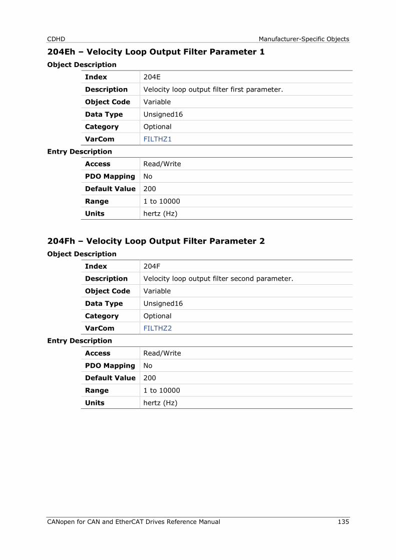
CDHD Manufacturer-Specific Objects
CANopen for CAN and EtherCAT Drives Reference Manual 135
204Eh – Velocity Loop Output Filter Parameter 1 Object Description
Index 204E
Description Velocity loop output filter first parameter.
Object Code Variable
Data Type Unsigned16
Category Optional
VarCom FILTHZ1
Entry Description
Access Read/Write
PDO Mapping No
Default Value 200
Range 1 to 10000
Units hertz (Hz)
204Fh – Velocity Loop Output Filter Parameter 2 Object Description
Index 204F
Description Velocity loop output filter second parameter.
Object Code Variable
Data Type Unsigned16
Category Optional
VarCom FILTHZ2
Entry Description
Access Read/Write
PDO Mapping No
Default Value 200
Range 1 to 10000
Units hertz (Hz)
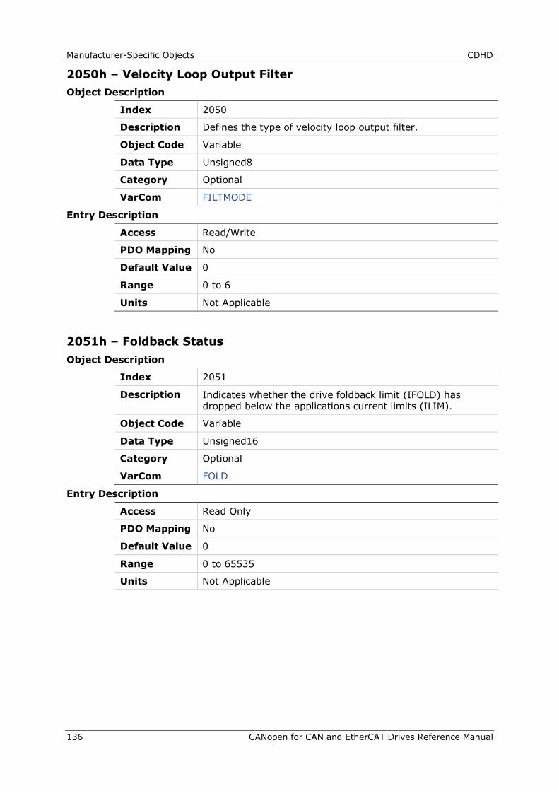
Manufacturer-Specific Objects CDHD
136 CANopen for CAN and EtherCAT Drives Reference Manual
2050h – Velocity Loop Output Filter Object Description
Index 2050
Description Defines the type of velocity loop output filter.
Object Code Variable
Data Type Unsigned8
Category Optional
VarCom FILTMODE
Entry Description
Access Read/Write
PDO Mapping No
Default Value 0
Range 0 to 6
Units Not Applicable
2051h – Foldback Status Object Description
Index 2051
Description Indicates whether the drive foldback limit (IFOLD) has dropped below the applications current limits (ILIM).
Object Code Variable
Data Type Unsigned16
Category Optional
VarCom FOLD
Entry Description
Access Read Only
PDO Mapping No
Default Value 0
Range 0 to 65535
Units Not Applicable
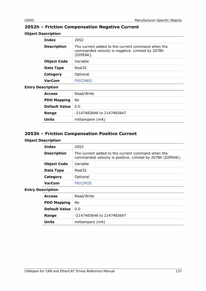
CDHD Manufacturer-Specific Objects
CANopen for CAN and EtherCAT Drives Reference Manual 137
2052h – Friction Compensation Negative Current Object Description
Index 2052
Description The current added to the current command when the commanded velocity is negative. Limited by 207Bh (DIPEAK).
Object Code Variable
Data Type Real32
Category Optional
VarCom FRICINEG
Entry Description
Access Read/Write
PDO Mapping No
Default Value 0.0
Range -2147483648 to 2147483647
Units milliampere (mA)
2053h – Friction Compensation Positive Current Object Description
Index 2053
Description The current added to the current command when the commanded velocity is positive. Limited by 207Bh (DIPEAK).
Object Code Variable
Data Type Real32
Category Optional
VarCom FRICIPOS
Entry Description
Access Read/Write
PDO Mapping No
Default Value 0.0
Range -2147483648 to 2147483647
Units milliampere (mA)
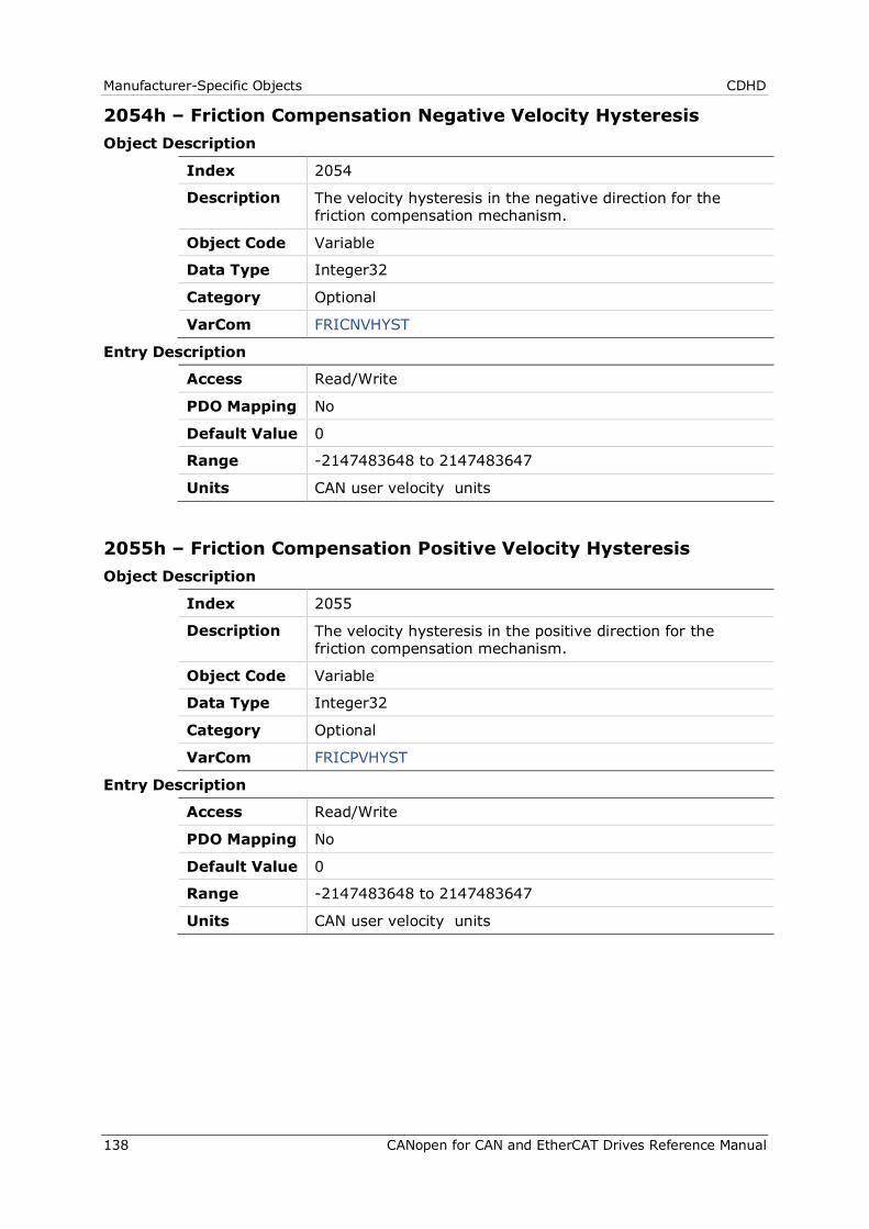
Manufacturer-Specific Objects CDHD
138 CANopen for CAN and EtherCAT Drives Reference Manual
2054h – Friction Compensation Negative Velocity Hysteresis Object Description
Index 2054
Description The velocity hysteresis in the negative direction for the friction compensation mechanism.
Object Code Variable
Data Type Integer32
Category Optional
VarCom FRICNVHYST
Entry Description
Access Read/Write
PDO Mapping No
Default Value 0
Range -2147483648 to 2147483647
Units CAN user velocity units
2055h – Friction Compensation Positive Velocity Hysteresis Object Description
Index 2055
Description The velocity hysteresis in the positive direction for the friction compensation mechanism.
Object Code Variable
Data Type Integer32
Category Optional
VarCom FRICPVHYST
Entry Description
Access Read/Write
PDO Mapping No
Default Value 0
Range -2147483648 to 2147483647
Units CAN user velocity units
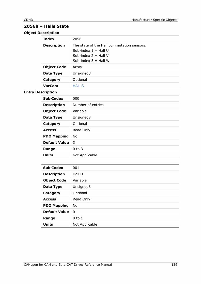
CDHD Manufacturer-Specific Objects
CANopen for CAN and EtherCAT Drives Reference Manual 139
2056h – Halls State Object Description
Index 2056
Description The state of the Hall commutation sensors. Sub-index 1 = Hall U Sub-index 2 = Hall V Sub-index 3 = Hall W
Object Code Array
Data Type Unsigned8
Category Optional
VarCom HALLS
Entry Description
Sub-Index 000
Description Number of entries
Object Code Variable
Data Type Unsigned8
Category Optional
Access Read Only
PDO Mapping No
Default Value 3
Range 0 to 3
Units Not Applicable
Sub-Index 001
Description Hall U
Object Code Variable
Data Type Unsigned8
Category Optional
Access Read Only
PDO Mapping No
Default Value 0
Range 0 to 1
Units Not Applicable
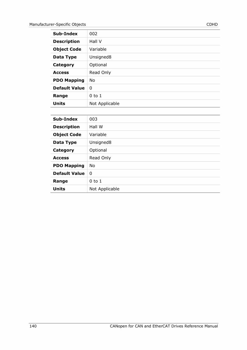
Manufacturer-Specific Objects CDHD
140 CANopen for CAN and EtherCAT Drives Reference Manual
Sub-Index 002
Description Hall V
Object Code Variable
Data Type Unsigned8
Category Optional
Access Read Only
PDO Mapping No
Default Value 0
Range 0 to 1
Units Not Applicable
Sub-Index 003
Description Hall W
Object Code Variable
Data Type Unsigned8
Category Optional
Access Read Only
PDO Mapping No
Default Value 0
Range 0 to 1
Units Not Applicable
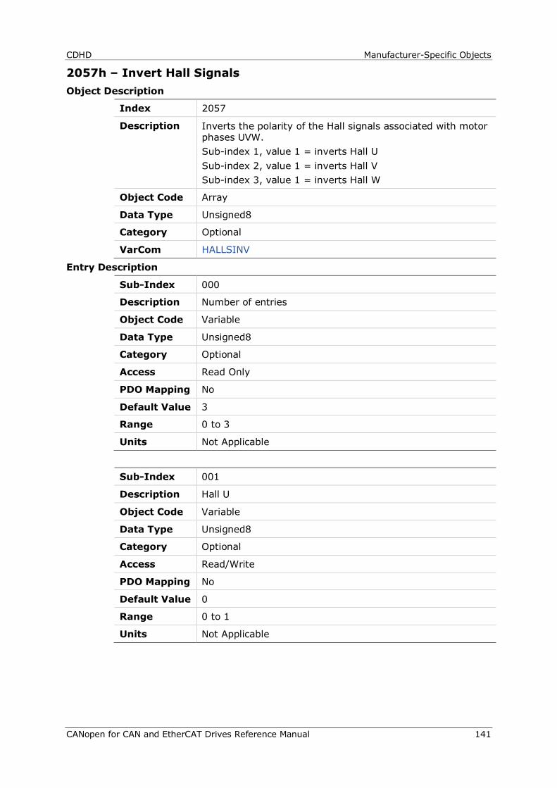
CDHD Manufacturer-Specific Objects
CANopen for CAN and EtherCAT Drives Reference Manual 141
2057h – Invert Hall Signals Object Description
Index 2057
Description Inverts the polarity of the Hall signals associated with motor phases UVW. Sub-index 1, value 1 = inverts Hall U Sub-index 2, value 1 = inverts Hall V Sub-index 3, value 1 = inverts Hall W
Object Code Array
Data Type Unsigned8
Category Optional
VarCom HALLSINV
Entry Description
Sub-Index 000
Description Number of entries
Object Code Variable
Data Type Unsigned8
Category Optional
Access Read Only
PDO Mapping No
Default Value 3
Range 0 to 3
Units Not Applicable
Sub-Index 001
Description Hall U
Object Code Variable
Data Type Unsigned8
Category Optional
Access Read/Write
PDO Mapping No
Default Value 0
Range 0 to 1
Units Not Applicable
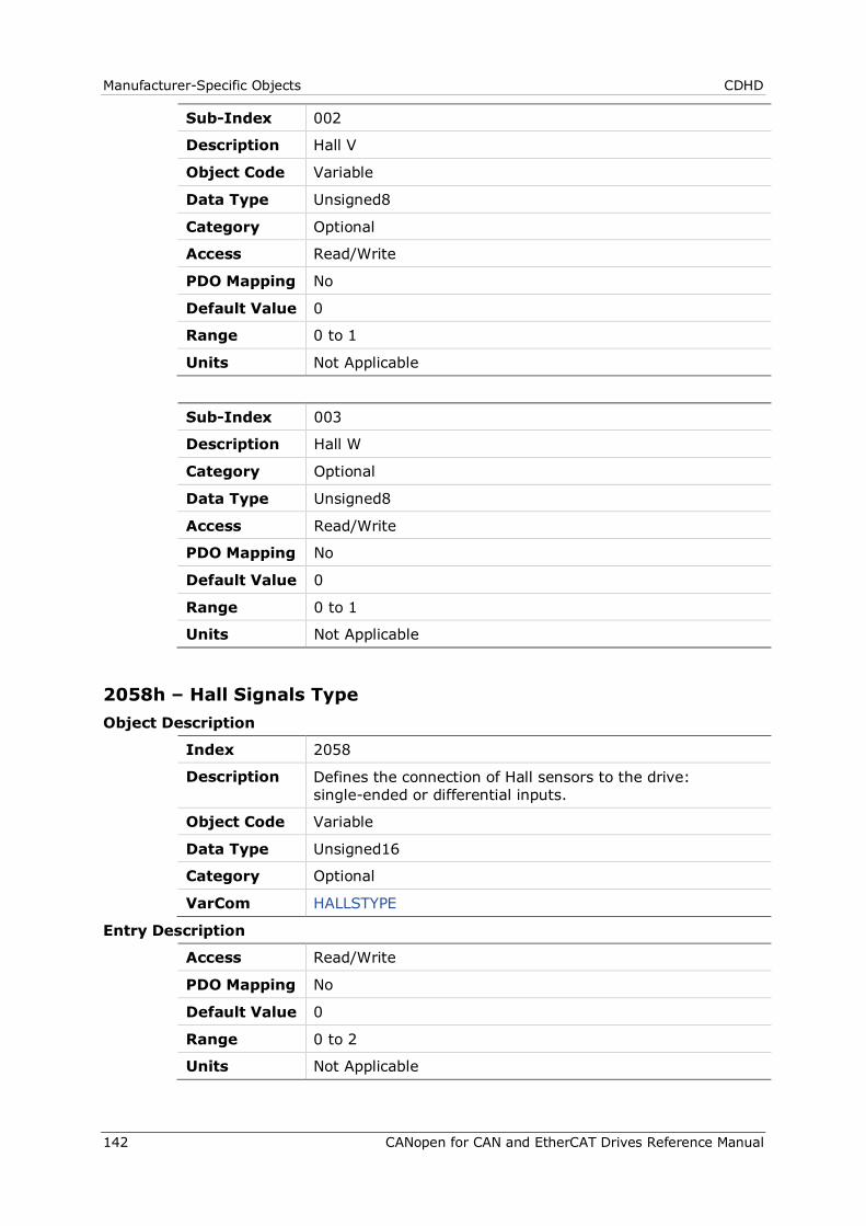
Manufacturer-Specific Objects CDHD
142 CANopen for CAN and EtherCAT Drives Reference Manual
Sub-Index 002
Description Hall V
Object Code Variable
Data Type Unsigned8
Category Optional
Access Read/Write
PDO Mapping No
Default Value 0
Range 0 to 1
Units Not Applicable
Sub-Index 003
Description Hall W
Category Optional
Data Type Unsigned8
Access Read/Write
PDO Mapping No
Default Value 0
Range 0 to 1
Units Not Applicable
2058h – Hall Signals Type Object Description
Index 2058
Description Defines the connection of Hall sensors to the drive: single-ended or differential inputs.
Object Code Variable
Data Type Unsigned16
Category Optional
VarCom HALLSTYPE
Entry Description
Access Read/Write
PDO Mapping No
Default Value 0
Range 0 to 2
Units Not Applicable
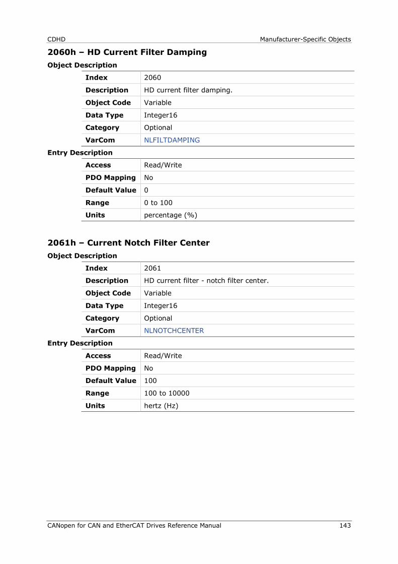
CDHD Manufacturer-Specific Objects
CANopen for CAN and EtherCAT Drives Reference Manual 143
2060h – HD Current Filter Damping Object Description
Index 2060
Description HD current filter damping.
Object Code Variable
Data Type Integer16
Category Optional
VarCom NLFILTDAMPING
Entry Description
Access Read/Write
PDO Mapping No
Default Value 0
Range 0 to 100
Units percentage (%)
2061h – Current Notch Filter Center Object Description
Index 2061
Description HD current filter - notch filter center.
Object Code Variable
Data Type Integer16
Category Optional
VarCom NLNOTCHCENTER
Entry Description
Access Read/Write
PDO Mapping No
Default Value 100
Range 100 to 10000
Units hertz (Hz)
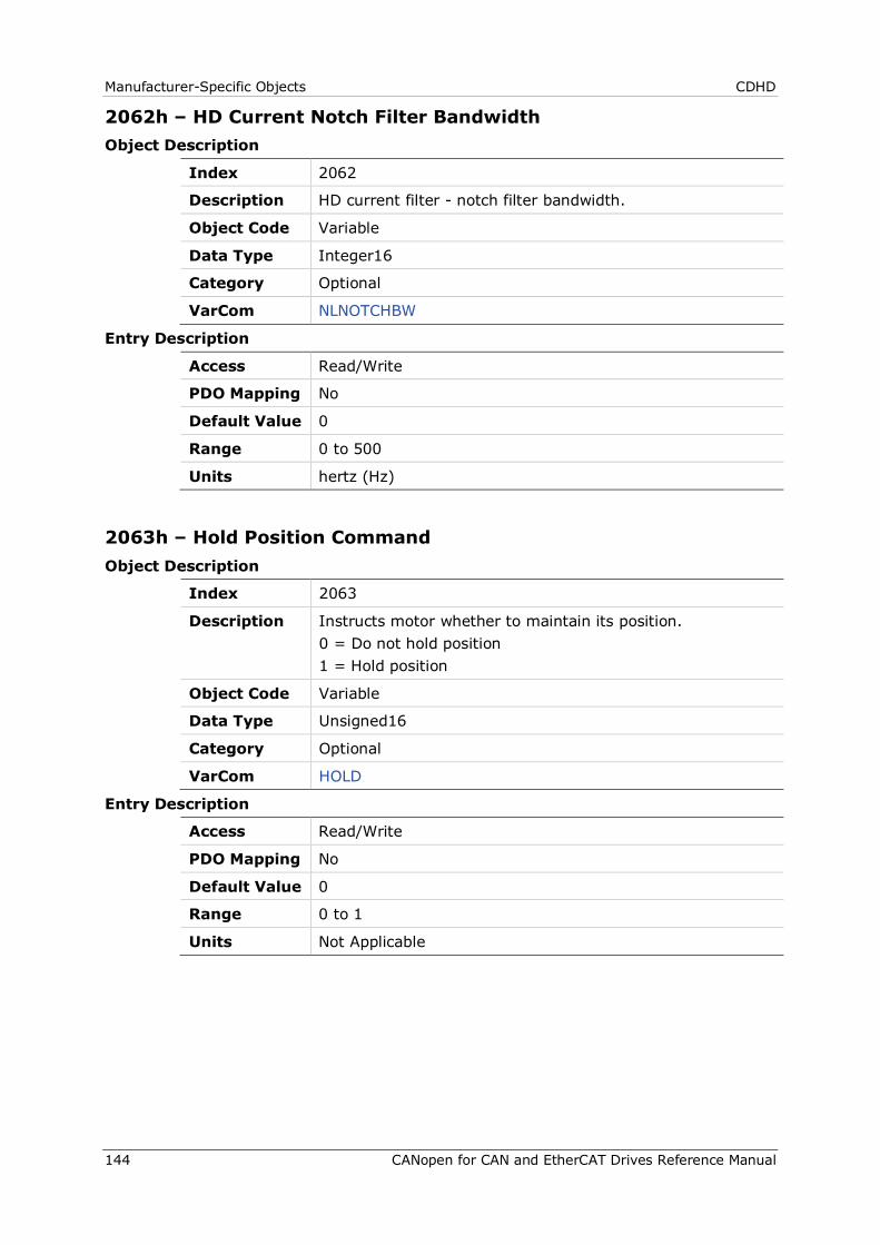
Manufacturer-Specific Objects CDHD
144 CANopen for CAN and EtherCAT Drives Reference Manual
2062h – HD Current Notch Filter Bandwidth Object Description
Index 2062
Description HD current filter - notch filter bandwidth.
Object Code Variable
Data Type Integer16
Category Optional
VarCom NLNOTCHBW
Entry Description
Access Read/Write
PDO Mapping No
Default Value 0
Range 0 to 500
Units hertz (Hz)
2063h – Hold Position Command Object Description
Index 2063
Description Instructs motor whether to maintain its position. 0 = Do not hold position 1 = Hold position
Object Code Variable
Data Type Unsigned16
Category Optional
VarCom HOLD
Entry Description
Access Read/Write
PDO Mapping No
Default Value 0
Range 0 to 1
Units Not Applicable
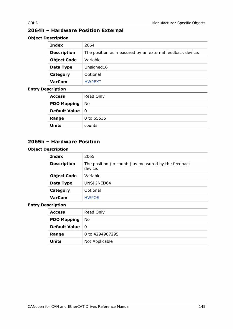
CDHD Manufacturer-Specific Objects
CANopen for CAN and EtherCAT Drives Reference Manual 145
2064h – Hardware Position External Object Description
Index 2064
Description The position as measured by an external feedback device.
Object Code Variable
Data Type Unsigned16
Category Optional
VarCom HWPEXT
Entry Description
Access Read Only
PDO Mapping No
Default Value 0
Range 0 to 65535
Units counts
2065h – Hardware Position Object Description
Index 2065
Description The position (in counts) as measured by the feedback device.
Object Code Variable
Data Type UNSIGNED64
Category Optional
VarCom HWPOS
Entry Description
Access Read Only
PDO Mapping No
Default Value 0
Range 0 to 4294967295
Units Not Applicable
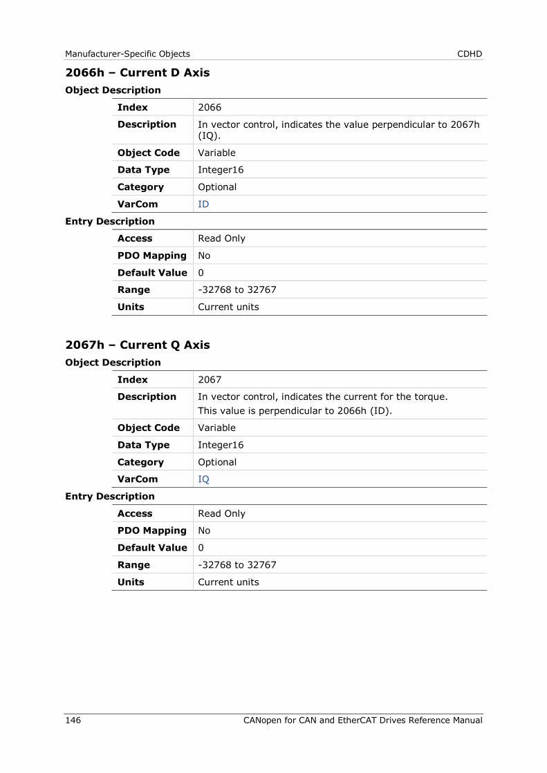
Manufacturer-Specific Objects CDHD
146 CANopen for CAN and EtherCAT Drives Reference Manual
2066h – Current D Axis Object Description
Index 2066
Description In vector control, indicates the value perpendicular to 2067h (IQ).
Object Code Variable
Data Type Integer16
Category Optional
VarCom ID
Entry Description
Access Read Only
PDO Mapping No
Default Value 0
Range -32768 to 32767
Units Current units
2067h – Current Q Axis Object Description
Index 2067
Description In vector control, indicates the current for the torque. This value is perpendicular to 2066h (ID).
Object Code Variable
Data Type Integer16
Category Optional
VarCom IQ
Entry Description
Access Read Only
PDO Mapping No
Default Value 0
Range -32768 to 32767
Units Current units
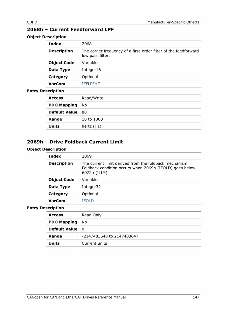
CDHD Manufacturer-Specific Objects
CANopen for CAN and EtherCAT Drives Reference Manual 147
2068h – Current Feedforward LPF Object Description
Index 2068
Description The corner frequency of a first-order filter of the feedforward low pass filter.
Object Code Variable
Data Type Integer16
Category Optional
VarCom IFFLPFHZ
Entry Description
Access Read/Write
PDO Mapping No
Default Value 80
Range 10 to 1000
Units hertz (Hz)
2069h – Drive Foldback Current Limit Object Description
Index 2069
Description The current limit derived from the foldback mechanism Foldback condition occurs when 2069h (IFOLD) goes below 6072h (ILIM).
Object Code Variable
Data Type Integer32
Category Optional
VarCom IFOLD
Entry Description
Access Read Only
PDO Mapping No
Default Value 0
Range -2147483648 to 2147483647
Units Current units
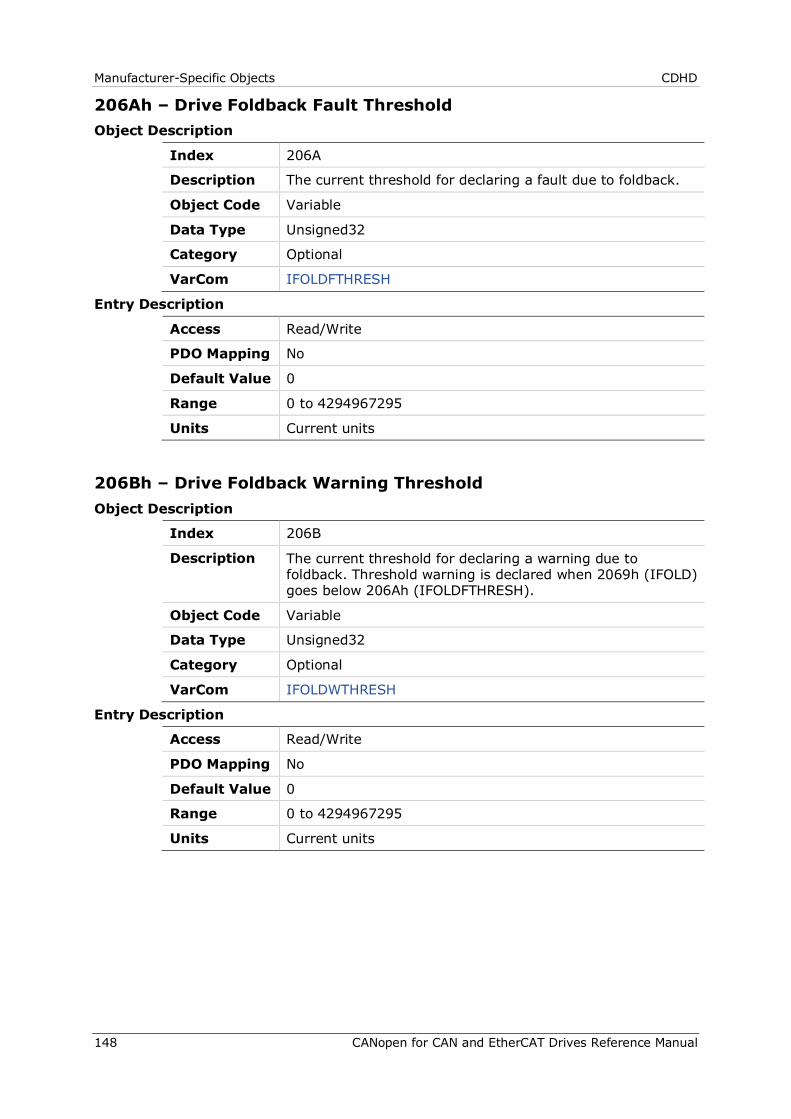
Manufacturer-Specific Objects CDHD
148 CANopen for CAN and EtherCAT Drives Reference Manual
206Ah – Drive Foldback Fault Threshold Object Description
Index 206A
Description The current threshold for declaring a fault due to foldback.
Object Code Variable
Data Type Unsigned32
Category Optional
VarCom IFOLDFTHRESH
Entry Description
Access Read/Write
PDO Mapping No
Default Value 0
Range 0 to 4294967295
Units Current units
206Bh – Drive Foldback Warning Threshold Object Description
Index 206B
Description The current threshold for declaring a warning due to foldback. Threshold warning is declared when 2069h (IFOLD) goes below 206Ah (IFOLDFTHRESH).
Object Code Variable
Data Type Unsigned32
Category Optional
VarCom IFOLDWTHRESH
Entry Description
Access Read/Write
PDO Mapping No
Default Value 0
Range 0 to 4294967295
Units Current units
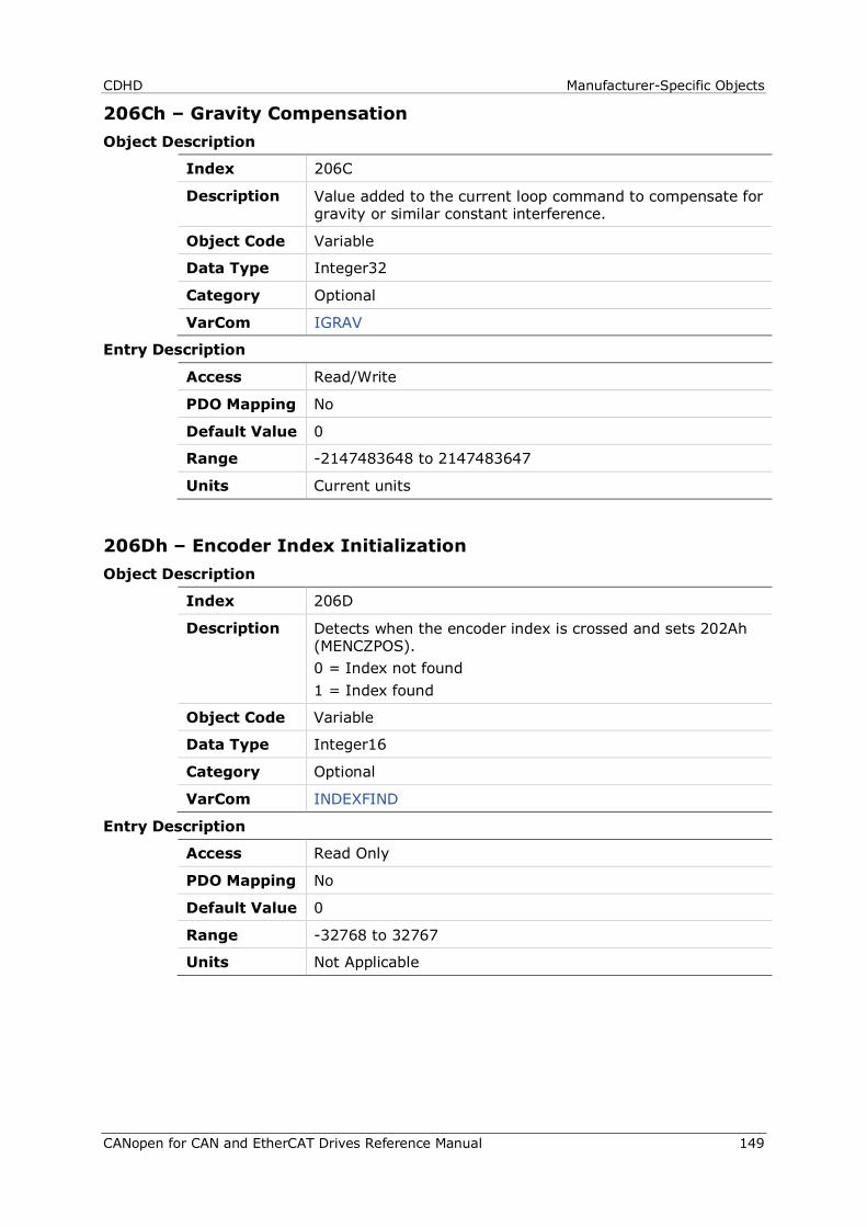
CDHD Manufacturer-Specific Objects
CANopen for CAN and EtherCAT Drives Reference Manual 149
206Ch – Gravity Compensation Object Description
Index 206C
Description Value added to the current loop command to compensate for gravity or similar constant interference.
Object Code Variable
Data Type Integer32
Category Optional
VarCom IGRAV
Entry Description
Access Read/Write
PDO Mapping No
Default Value 0
Range -2147483648 to 2147483647
Units Current units
206Dh – Encoder Index Initialization Object Description
Index 206D
Description Detects when the encoder index is crossed and sets 202Ah (MENCZPOS). 0 = Index not found 1 = Index found
Object Code Variable
Data Type Integer16
Category Optional
VarCom INDEXFIND
Entry Description
Access Read Only
PDO Mapping No
Default Value 0
Range -32768 to 32767
Units Not Applicable
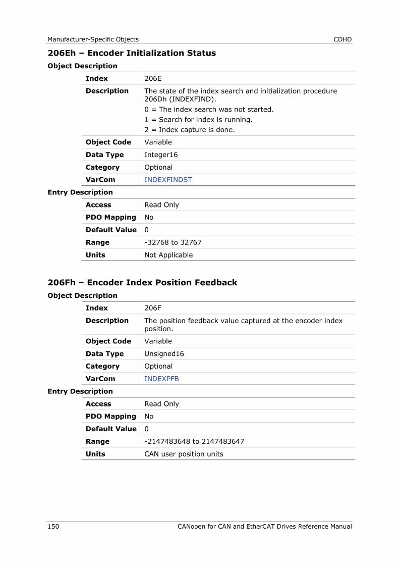
Manufacturer-Specific Objects CDHD
150 CANopen for CAN and EtherCAT Drives Reference Manual
206Eh – Encoder Initialization Status Object Description
Index 206E
Description The state of the index search and initialization procedure 206Dh (INDEXFIND). 0 = The index search was not started. 1 = Search for index is running. 2 = Index capture is done.
Object Code Variable
Data Type Integer16
Category Optional
VarCom INDEXFINDST
Entry Description
Access Read Only
PDO Mapping No
Default Value 0
Range -32768 to 32767
Units Not Applicable
206Fh – Encoder Index Position Feedback Object Description
Index 206F
Description The position feedback value captured at the encoder index position.
Object Code Variable
Data Type Unsigned16
Category Optional
VarCom INDEXPFB
Entry Description
Access Read Only
PDO Mapping No
Default Value 0
Range -2147483648 to 2147483647
Units CAN user position units
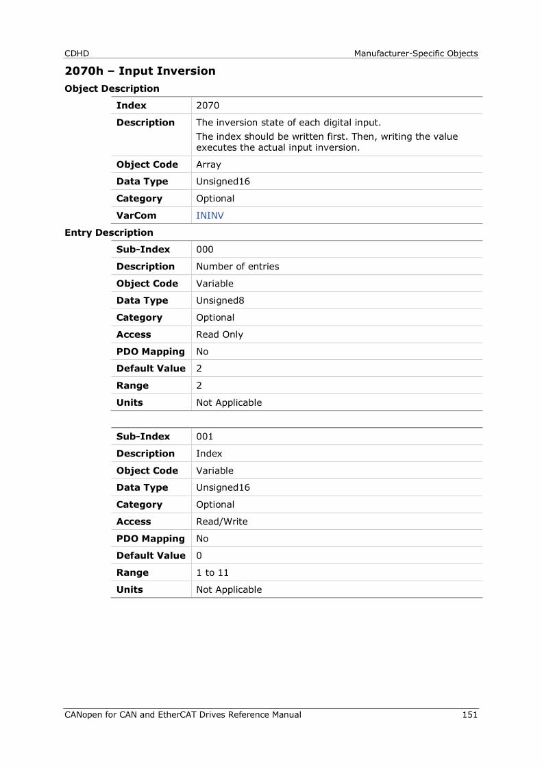
CDHD Manufacturer-Specific Objects
CANopen for CAN and EtherCAT Drives Reference Manual 151
2070h – Input Inversion Object Description
Index 2070
Description The inversion state of each digital input. The index should be written first. Then, writing the value executes the actual input inversion.
Object Code Array
Data Type Unsigned16
Category Optional
VarCom ININV
Entry Description
Sub-Index 000
Description Number of entries
Object Code Variable
Data Type Unsigned8
Category Optional
Access Read Only
PDO Mapping No
Default Value 2
Range 2
Units Not Applicable
Sub-Index 001
Description Index
Object Code Variable
Data Type Unsigned16
Category Optional
Access Read/Write
PDO Mapping No
Default Value 0
Range 1 to 11
Units Not Applicable
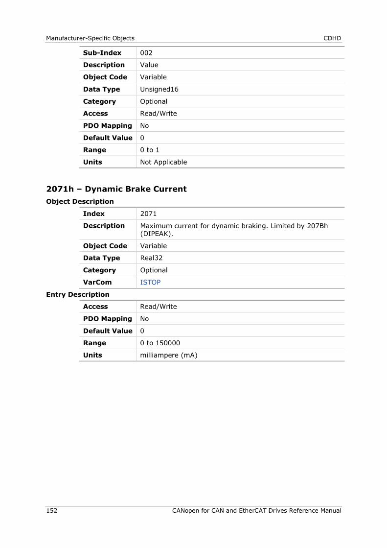
Manufacturer-Specific Objects CDHD
152 CANopen for CAN and EtherCAT Drives Reference Manual
Sub-Index 002
Description Value
Object Code Variable
Data Type Unsigned16
Category Optional
Access Read/Write
PDO Mapping No
Default Value 0
Range 0 to 1
Units Not Applicable
2071h – Dynamic Brake Current Object Description
Index 2071
Description Maximum current for dynamic braking. Limited by 207Bh (DIPEAK).
Object Code Variable
Data Type Real32
Category Optional
VarCom ISTOP
Entry Description
Access Read/Write
PDO Mapping No
Default Value 0
Range 0 to 150000
Units milliampere (mA)
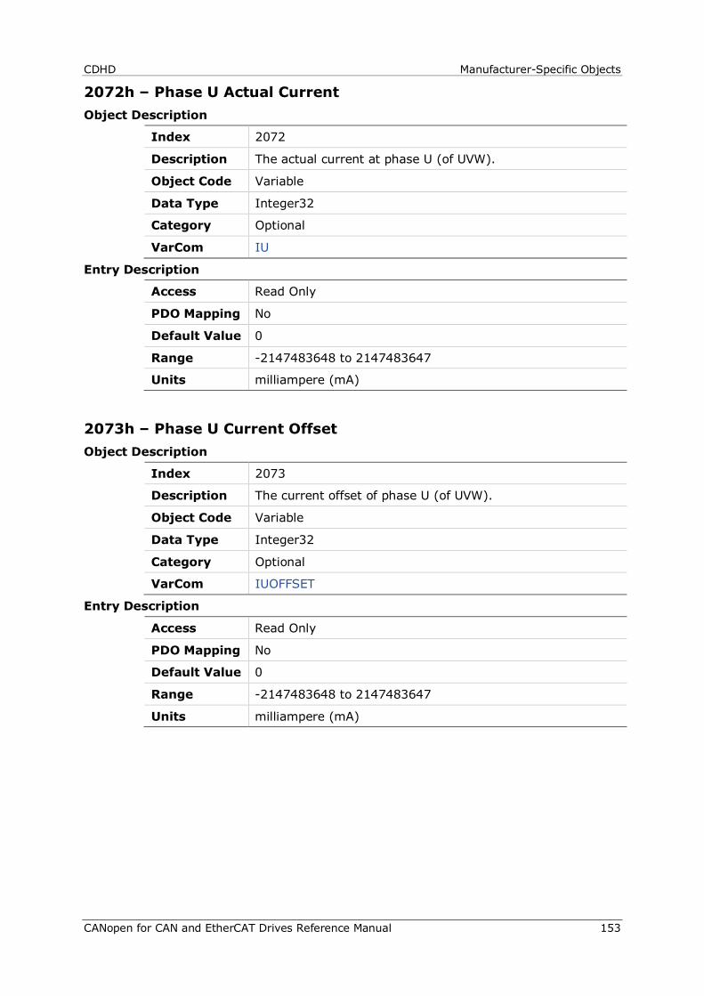
CDHD Manufacturer-Specific Objects
CANopen for CAN and EtherCAT Drives Reference Manual 153
2072h – Phase U Actual Current Object Description
Index 2072
Description The actual current at phase U (of UVW).
Object Code Variable
Data Type Integer32
Category Optional
VarCom IU
Entry Description
Access Read Only
PDO Mapping No
Default Value 0
Range -2147483648 to 2147483647
Units milliampere (mA)
2073h – Phase U Current Offset Object Description
Index 2073
Description The current offset of phase U (of UVW).
Object Code Variable
Data Type Integer32
Category Optional
VarCom IUOFFSET
Entry Description
Access Read Only
PDO Mapping No
Default Value 0
Range -2147483648 to 2147483647
Units milliampere (mA)
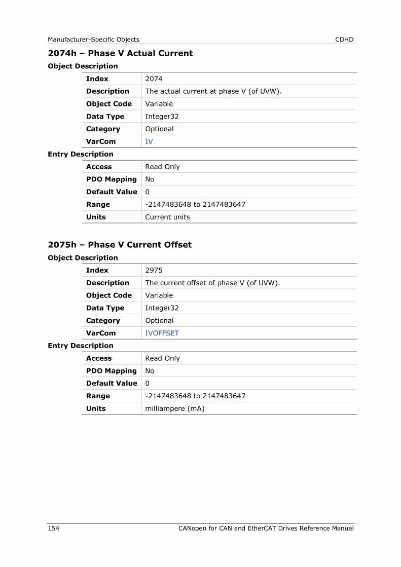
Manufacturer-Specific Objects CDHD
154 CANopen for CAN and EtherCAT Drives Reference Manual
2074h – Phase V Actual Current Object Description
Index 2074
Description The actual current at phase V (of UVW).
Object Code Variable
Data Type Integer32
Category Optional
VarCom IV
Entry Description
Access Read Only
PDO Mapping No
Default Value 0
Range -2147483648 to 2147483647
Units Current units
2075h – Phase V Current Offset Object Description
Index 2975
Description The current offset of phase V (of UVW).
Object Code Variable
Data Type Integer32
Category Optional
VarCom IVOFFSET
Entry Description
Access Read Only
PDO Mapping No
Default Value 0
Range -2147483648 to 2147483647
Units milliampere (mA)
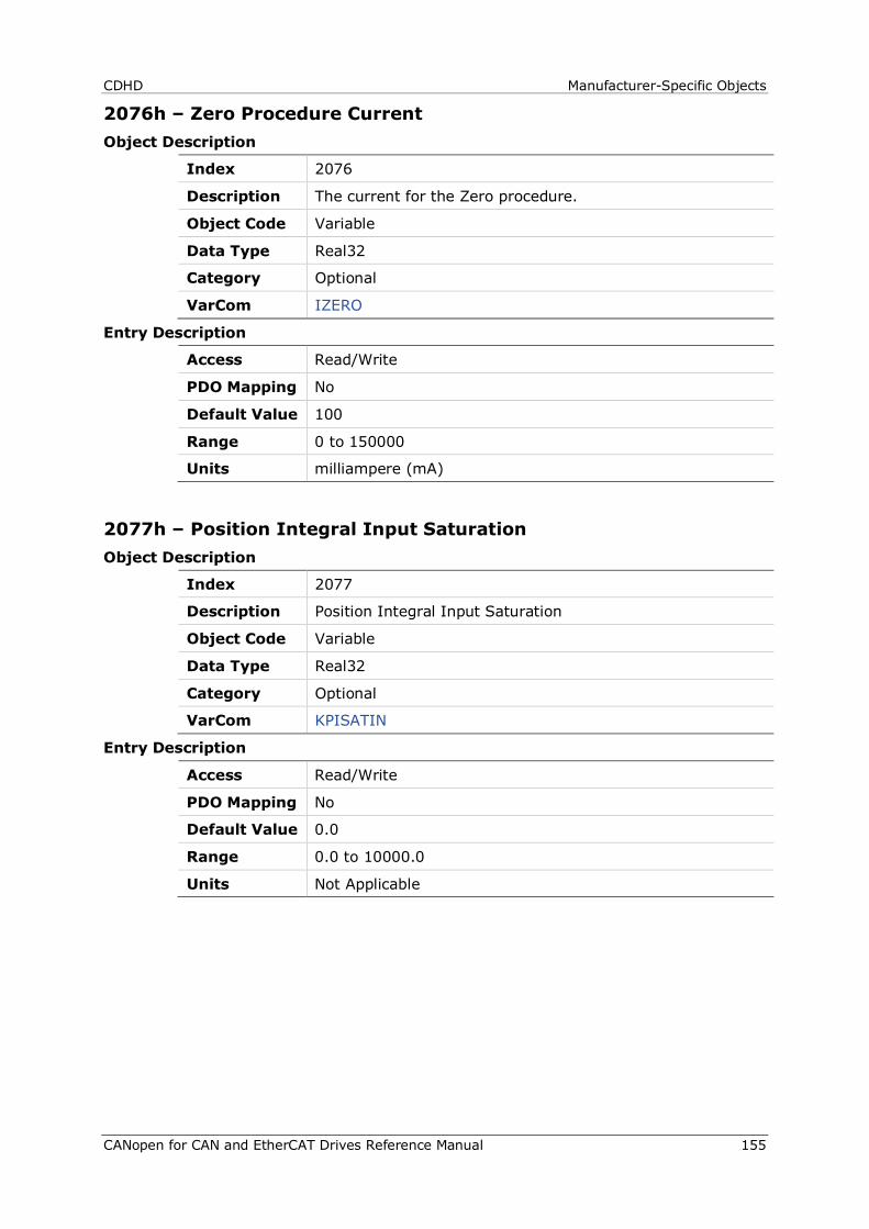
CDHD Manufacturer-Specific Objects
CANopen for CAN and EtherCAT Drives Reference Manual 155
2076h – Zero Procedure Current Object Description
Index 2076
Description The current for the Zero procedure.
Object Code Variable
Data Type Real32
Category Optional
VarCom IZERO
Entry Description
Access Read/Write
PDO Mapping No
Default Value 100
Range 0 to 150000
Units milliampere (mA)
2077h – Position Integral Input Saturation Object Description
Index 2077
Description Position Integral Input Saturation
Object Code Variable
Data Type Real32
Category Optional
VarCom KPISATIN
Entry Description
Access Read/Write
PDO Mapping No
Default Value 0.0
Range 0.0 to 10000.0
Units Not Applicable
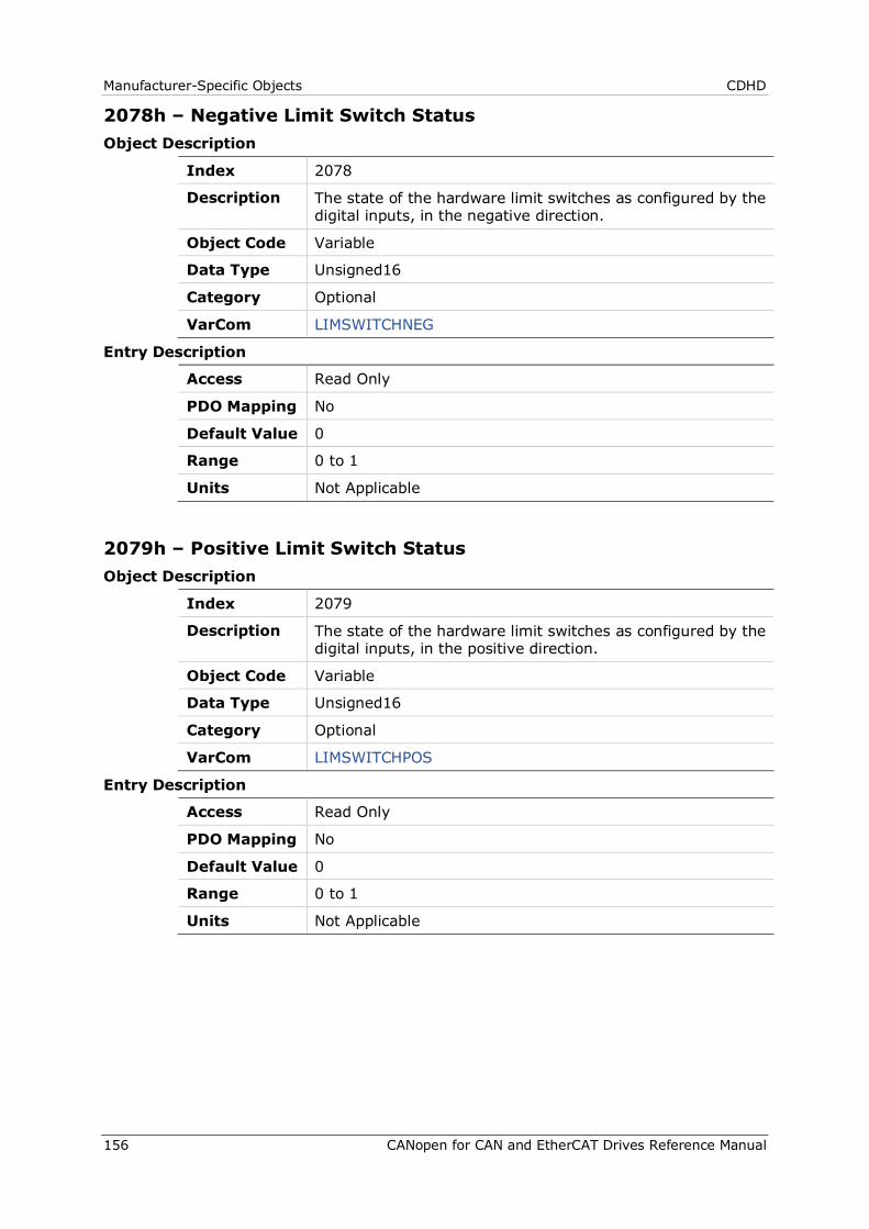
Manufacturer-Specific Objects CDHD
156 CANopen for CAN and EtherCAT Drives Reference Manual
2078h – Negative Limit Switch Status Object Description
Index 2078
Description The state of the hardware limit switches as configured by the digital inputs, in the negative direction.
Object Code Variable
Data Type Unsigned16
Category Optional
VarCom LIMSWITCHNEG
Entry Description
Access Read Only
PDO Mapping No
Default Value 0
Range 0 to 1
Units Not Applicable
2079h – Positive Limit Switch Status Object Description
Index 2079
Description The state of the hardware limit switches as configured by the digital inputs, in the positive direction.
Object Code Variable
Data Type Unsigned16
Category Optional
VarCom LIMSWITCHPOS
Entry Description
Access Read Only
PDO Mapping No
Default Value 0
Range 0 to 1
Units Not Applicable

CDHD Manufacturer-Specific Objects
CANopen for CAN and EtherCAT Drives Reference Manual 157
207Ah – Load to Motor Inertia Ratio Object Description
Index 207A
Description The ratio of the load inertia to the motor inertia.
Object Code Variable
Data Type Real32
Category Optional
VarCom LMJR
Entry Description
Access Read/Write
PDO Mapping No
Default Value 0.0
Range 0.0 to 600.0
Units Not Applicable
207Bh – Drive Peak Current Object Description
Index 207B
Description The peak rated current of the drive (sinusoidal peak).
Object Code Variable
Data Type Real32
Category Optional
VarCom DIPEAK
Entry Description
Access Read Only
PDO Mapping No
Default Value 25455
Range 1 to 4294967295
Units milliampere (mA)

Manufacturer-Specific Objects CDHD
158 CANopen for CAN and EtherCAT Drives Reference Manual
207Ch – Drive Continuous Current Object Description
Index 207C
Description The continuous rated current for the drive (sinusoidal peak).
Object Code Variable
Data Type Real32
Category Optional
VarCom DICONT
Entry Description
Access Read Only
PDO Mapping No
Default Value 8485
Range 1 to 4294967295
Units milliampere (mA)
207Dh – Motor Pitch Object Description
Index 207D
Description The pitch of a linear motor.
Object Code Variable
Data Type Unsigned32
Category Optional
VarCom MPITCH
Entry Description
Access Read/Write
PDO Mapping No
Default Value 32
Range 1 to 100000
Units millimeters (mm)
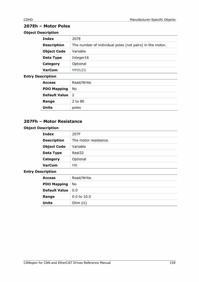
CDHD Manufacturer-Specific Objects
CANopen for CAN and EtherCAT Drives Reference Manual 159
207Eh – Motor Poles Object Description
Index 207E
Description The number of individual poles (not pairs) in the motor.
Object Code Variable
Data Type Integer16
Category Optional
VarCom MPOLES
Entry Description
Access Read/Write
PDO Mapping No
Default Value 2
Range 2 to 80
Units poles
207Fh – Motor Resistance Object Description
Index 207F
Description The motor resistance.
Object Code Variable
Data Type Real32
Category Optional
VarCom MR
Entry Description
Access Read/Write
PDO Mapping No
Default Value 0.0
Range 0.0 to 10.0
Units Ohm (Ω)

Manufacturer-Specific Objects CDHD
160 CANopen for CAN and EtherCAT Drives Reference Manual
2080h – Motor Resolver Poles Object Description
Index 2080
Description The number of individual poles in the resolver feedback device.
Object Code Variable
Data Type Integer16
Category Optional
VarCom MRESPOLES
Entry Description
Access Read/Write
PDO Mapping No
Default Value 2
Range 2 to 80
Units poles
2081h – Motor Rated Torque Object Description
Index 2081
Description Motor rated torque.
Object Code Variable
Data Type Unsigned32
Category Optional
Entry Description
Access Read/Write
PDO Mapping No
Default Value 2000
Range 1 to 4294967295
Units millinewton meter (mNm)
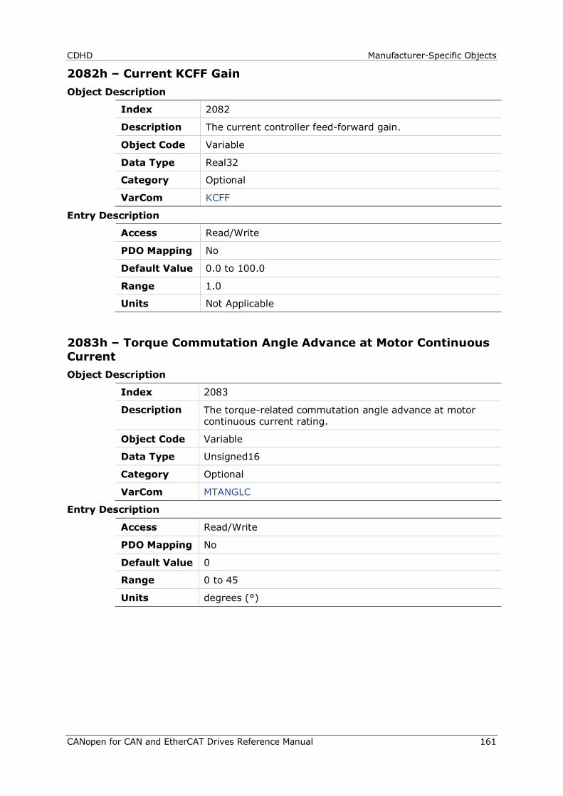
CDHD Manufacturer-Specific Objects
CANopen for CAN and EtherCAT Drives Reference Manual 161
2082h – Current KCFF Gain Object Description
Index 2082
Description The current controller feed-forward gain.
Object Code Variable
Data Type Real32
Category Optional
VarCom KCFF
Entry Description
Access Read/Write
PDO Mapping No
Default Value 0.0 to 100.0
Range 1.0
Units Not Applicable
2083h – Torque Commutation Angle Advance at Motor Continuous Current Object Description
Index 2083
Description The torque-related commutation angle advance at motor continuous current rating.
Object Code Variable
Data Type Unsigned16
Category Optional
VarCom MTANGLC
Entry Description
Access Read/Write
PDO Mapping No
Default Value 0
Range 0 to 45
Units degrees (°)
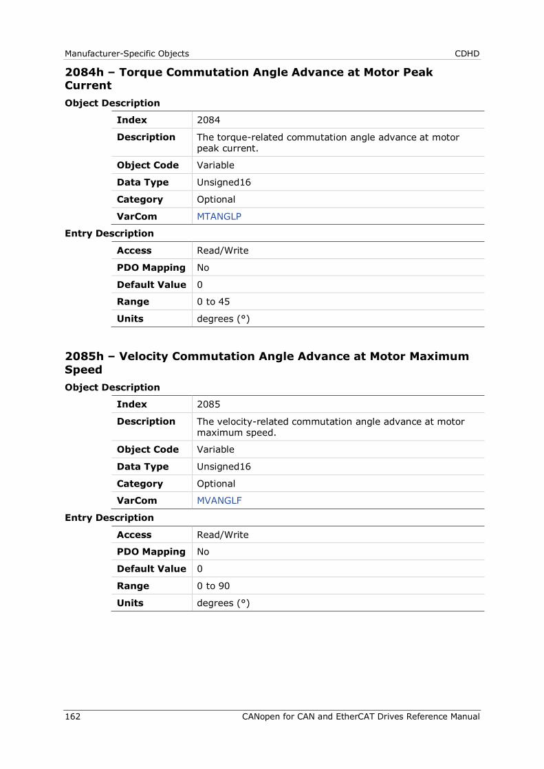
Manufacturer-Specific Objects CDHD
162 CANopen for CAN and EtherCAT Drives Reference Manual
2084h – Torque Commutation Angle Advance at Motor Peak Current Object Description
Index 2084
Description The torque-related commutation angle advance at motor peak current.
Object Code Variable
Data Type Unsigned16
Category Optional
VarCom MTANGLP
Entry Description
Access Read/Write
PDO Mapping No
Default Value 0
Range 0 to 45
Units degrees (°)
2085h – Velocity Commutation Angle Advance at Motor Maximum Speed Object Description
Index 2085
Description The velocity-related commutation angle advance at motor maximum speed.
Object Code Variable
Data Type Unsigned16
Category Optional
VarCom MVANGLF
Entry Description
Access Read/Write
PDO Mapping No
Default Value 0
Range 0 to 90
Units degrees (°)
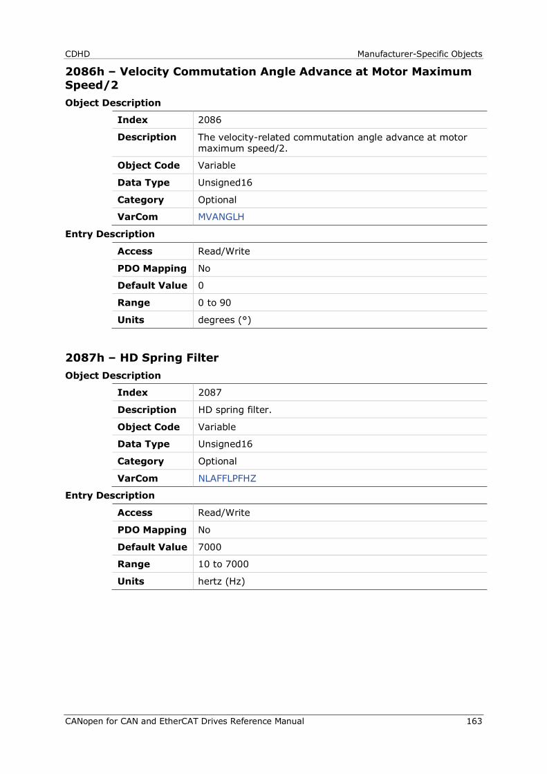
CDHD Manufacturer-Specific Objects
CANopen for CAN and EtherCAT Drives Reference Manual 163
2086h – Velocity Commutation Angle Advance at Motor Maximum Speed/2 Object Description
Index 2086
Description The velocity-related commutation angle advance at motor maximum speed/2.
Object Code Variable
Data Type Unsigned16
Category Optional
VarCom MVANGLH
Entry Description
Access Read/Write
PDO Mapping No
Default Value 0
Range 0 to 90
Units degrees (°)
2087h – HD Spring Filter Object Description
Index 2087
Description HD spring filter.
Object Code Variable
Data Type Unsigned16
Category Optional
VarCom NLAFFLPFHZ
Entry Description
Access Read/Write
PDO Mapping No
Default Value 7000
Range 10 to 7000
Units hertz (Hz)
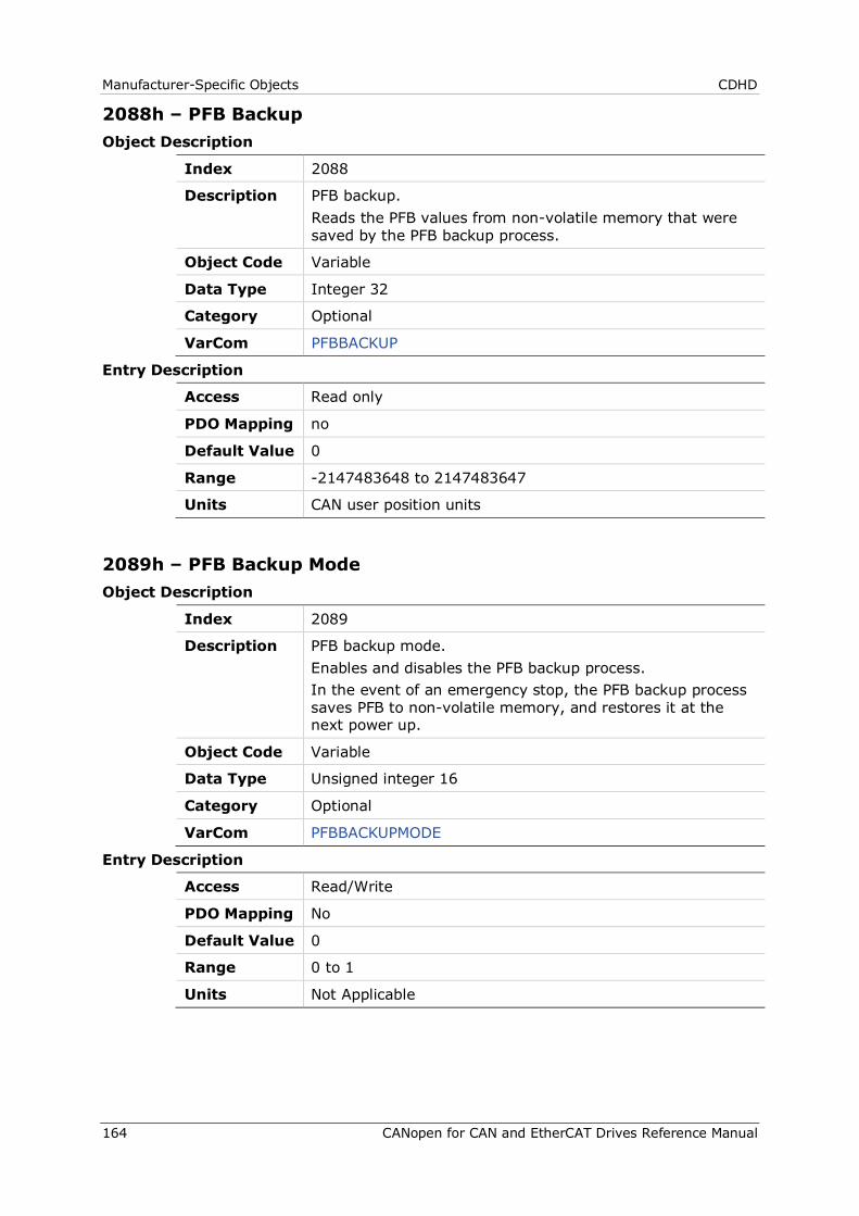
Manufacturer-Specific Objects CDHD
164 CANopen for CAN and EtherCAT Drives Reference Manual
2088h – PFB Backup Object Description
Index 2088
Description PFB backup. Reads the PFB values from non-volatile memory that were saved by the PFB backup process.
Object Code Variable
Data Type Integer 32
Category Optional
VarCom PFBBACKUP
Entry Description
Access Read only
PDO Mapping no
Default Value 0
Range -2147483648 to 2147483647
Units CAN user position units
2089h – PFB Backup Mode Object Description
Index 2089
Description PFB backup mode. Enables and disables the PFB backup process. In the event of an emergency stop, the PFB backup process saves PFB to non-volatile memory, and restores it at the next power up.
Object Code Variable
Data Type Unsigned integer 16
Category Optional
VarCom PFBBACKUPMODE
Entry Description
Access Read/Write
PDO Mapping No
Default Value 0
Range 0 to 1
Units Not Applicable
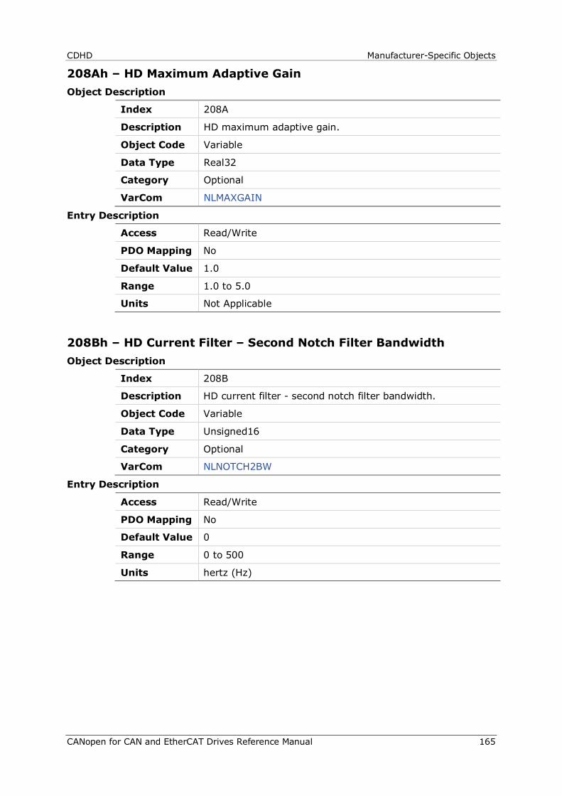
CDHD Manufacturer-Specific Objects
CANopen for CAN and EtherCAT Drives Reference Manual 165
208Ah – HD Maximum Adaptive Gain Object Description
Index 208A
Description HD maximum adaptive gain.
Object Code Variable
Data Type Real32
Category Optional
VarCom NLMAXGAIN
Entry Description
Access Read/Write
PDO Mapping No
Default Value 1.0
Range 1.0 to 5.0
Units Not Applicable
208Bh – HD Current Filter – Second Notch Filter Bandwidth Object Description
Index 208B
Description HD current filter - second notch filter bandwidth.
Object Code Variable
Data Type Unsigned16
Category Optional
VarCom NLNOTCH2BW
Entry Description
Access Read/Write
PDO Mapping No
Default Value 0
Range 0 to 500
Units hertz (Hz)
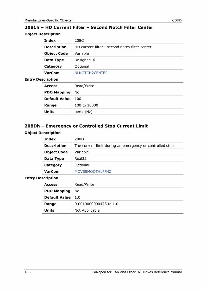
Manufacturer-Specific Objects CDHD
166 CANopen for CAN and EtherCAT Drives Reference Manual
208Ch – HD Current Filter – Second Notch Filter Center Object Description
Index 208C
Description HD current filter - second notch filter center
Object Code Variable
Data Type Unsigned16
Category Optional
VarCom NLNOTCH2CENTER
Entry Description
Access Read/Write
PDO Mapping No
Default Value 100
Range 100 to 10000
Units hertz (Hz)
208Dh – Emergency or Controlled Stop Current Limit Object Description
Index 208D
Description The current limit during an emergency or controlled stop
Object Code Variable
Data Type Real32
Category Optional
VarCom MOVESMOOTHLPFHZ
Entry Description
Access Read/Write
PDO Mapping No
Default Value 1.0
Range 0.0010000000475 to 1.0
Units Not Applicable
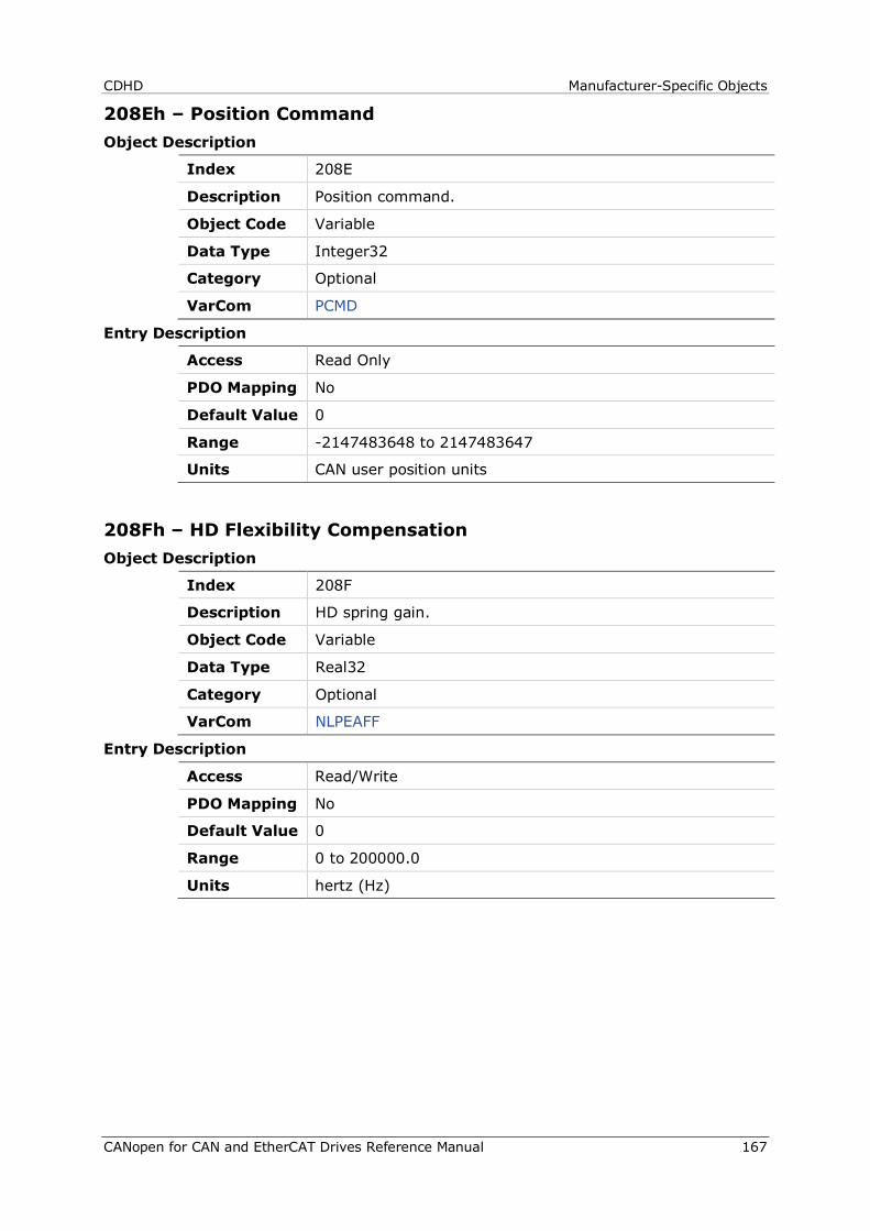
CDHD Manufacturer-Specific Objects
CANopen for CAN and EtherCAT Drives Reference Manual 167
208Eh – Position Command Object Description
Index 208E
Description Position command.
Object Code Variable
Data Type Integer32
Category Optional
VarCom PCMD
Entry Description
Access Read Only
PDO Mapping No
Default Value 0
Range -2147483648 to 2147483647
Units CAN user position units
208Fh – HD Flexibility Compensation Object Description
Index 208F
Description HD spring gain.
Object Code Variable
Data Type Real32
Category Optional
VarCom NLPEAFF
Entry Description
Access Read/Write
PDO Mapping No
Default Value 0
Range 0 to 200000.0
Units hertz (Hz)
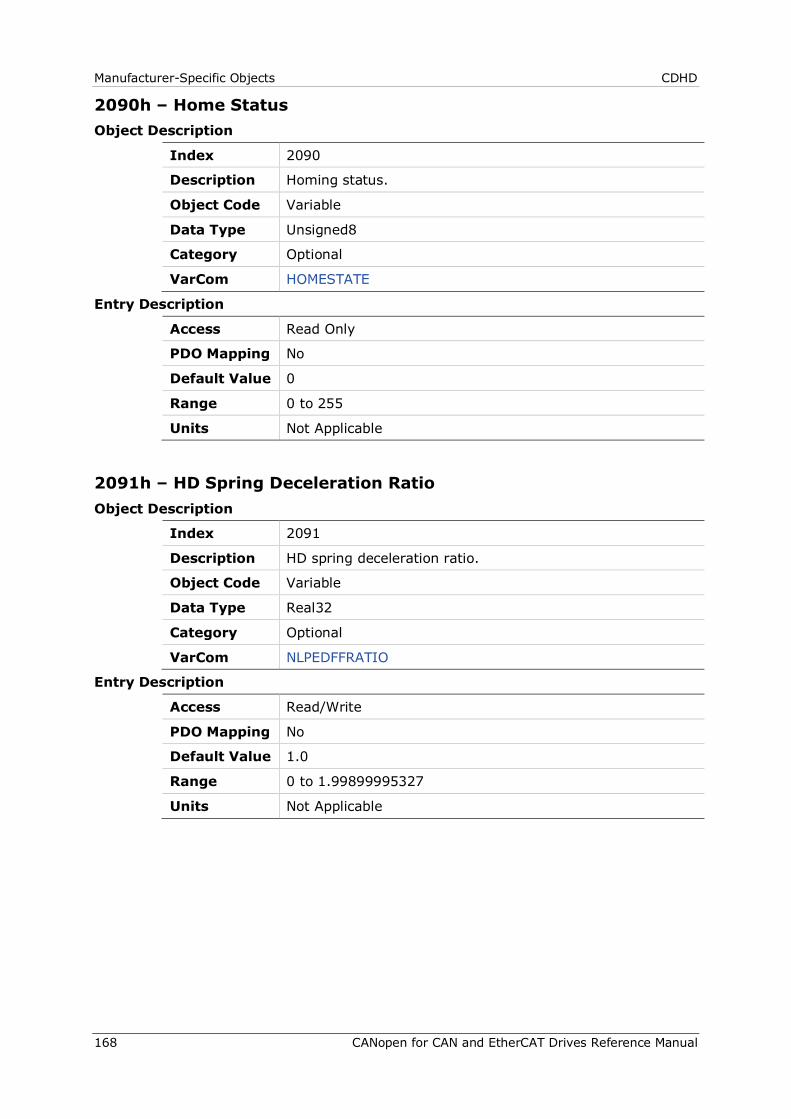
Manufacturer-Specific Objects CDHD
168 CANopen for CAN and EtherCAT Drives Reference Manual
2090h – Home Status Object Description
Index 2090
Description Homing status.
Object Code Variable
Data Type Unsigned8
Category Optional
VarCom HOMESTATE
Entry Description
Access Read Only
PDO Mapping No
Default Value 0
Range 0 to 255
Units Not Applicable
2091h – HD Spring Deceleration Ratio Object Description
Index 2091
Description HD spring deceleration ratio.
Object Code Variable
Data Type Real32
Category Optional
VarCom NLPEDFFRATIO
Entry Description
Access Read/Write
PDO Mapping No
Default Value 1.0
Range 0 to 1.99899995327
Units Not Applicable
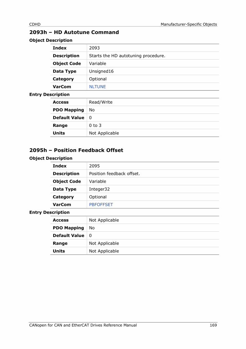
CDHD Manufacturer-Specific Objects
CANopen for CAN and EtherCAT Drives Reference Manual 169
2093h – HD Autotune Command Object Description
Index 2093
Description Starts the HD autotuning procedure.
Object Code Variable
Data Type Unsigned16
Category Optional
VarCom NLTUNE
Entry Description
Access Read/Write
PDO Mapping No
Default Value 0
Range 0 to 3
Units Not Applicable
2095h – Position Feedback Offset Object Description
Index 2095
Description Position feedback offset.
Object Code Variable
Data Type Integer32
Category Optional
VarCom PBFOFFSET
Entry Description
Access Not Applicable
PDO Mapping No
Default Value 0
Range Not Applicable
Units Not Applicable
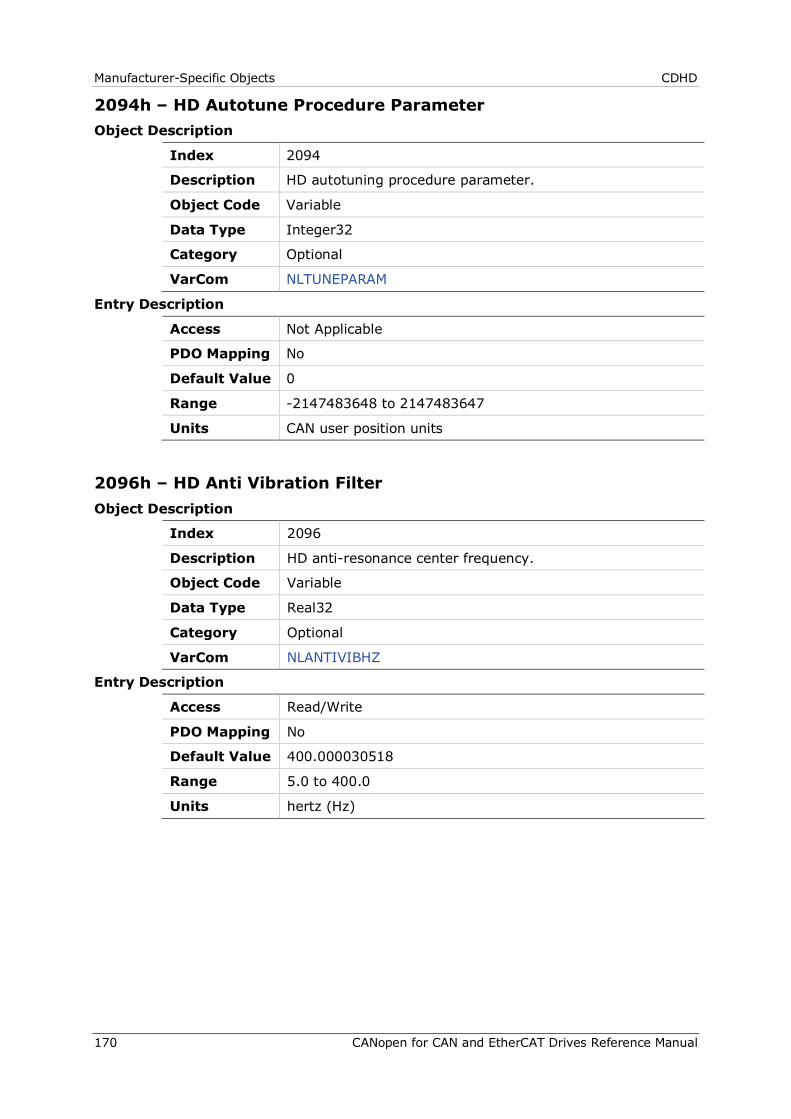
Manufacturer-Specific Objects CDHD
170 CANopen for CAN and EtherCAT Drives Reference Manual
2094h – HD Autotune Procedure Parameter Object Description
Index 2094
Description HD autotuning procedure parameter.
Object Code Variable
Data Type Integer32
Category Optional
VarCom NLTUNEPARAM
Entry Description
Access Not Applicable
PDO Mapping No
Default Value 0
Range -2147483648 to 2147483647
Units CAN user position units
2096h – HD Anti Vibration Filter Object Description
Index 2096
Description HD anti-resonance center frequency.
Object Code Variable
Data Type Real32
Category Optional
VarCom NLANTIVIBHZ
Entry Description
Access Read/Write
PDO Mapping No
Default Value 400.000030518
Range 5.0 to 400.0
Units hertz (Hz)
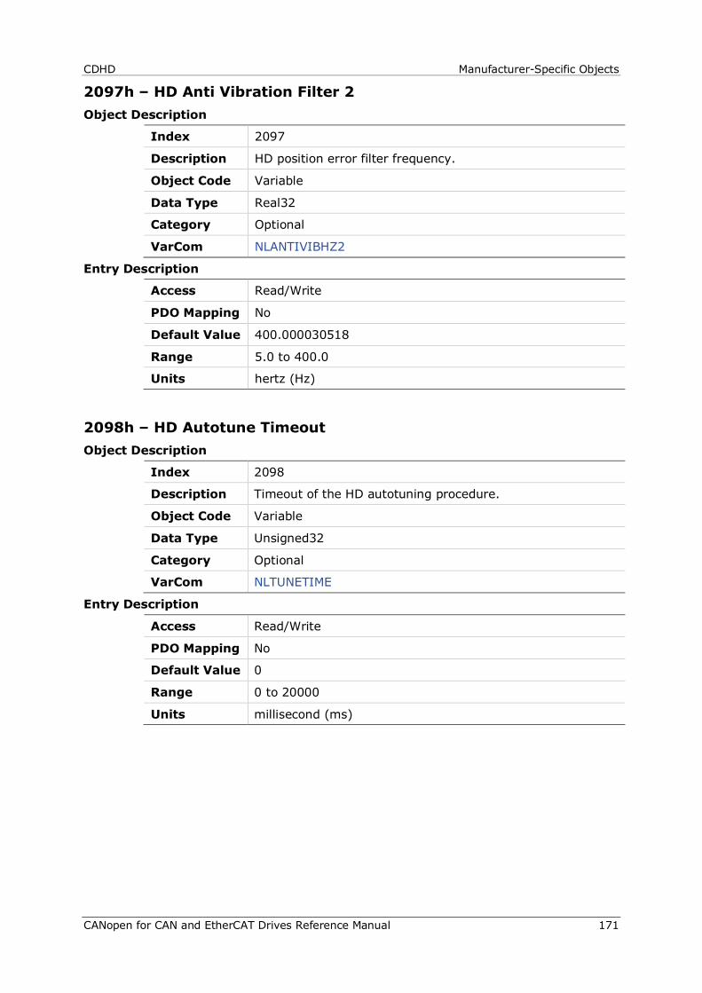
CDHD Manufacturer-Specific Objects
CANopen for CAN and EtherCAT Drives Reference Manual 171
2097h – HD Anti Vibration Filter 2 Object Description
Index 2097
Description HD position error filter frequency.
Object Code Variable
Data Type Real32
Category Optional
VarCom NLANTIVIBHZ2
Entry Description
Access Read/Write
PDO Mapping No
Default Value 400.000030518
Range 5.0 to 400.0
Units hertz (Hz)
2098h – HD Autotune Timeout Object Description
Index 2098
Description Timeout of the HD autotuning procedure.
Object Code Variable
Data Type Unsigned32
Category Optional
VarCom NLTUNETIME
Entry Description
Access Read/Write
PDO Mapping No
Default Value 0
Range 0 to 20000
Units millisecond (ms)
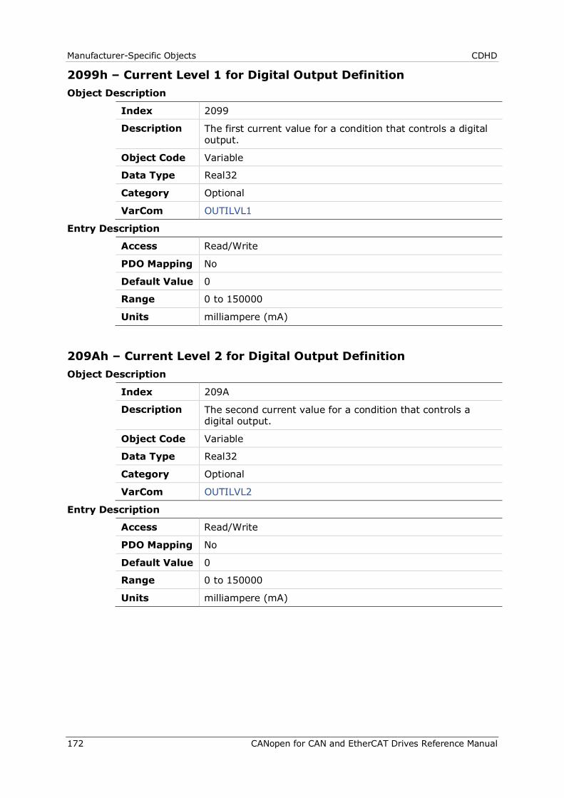
Manufacturer-Specific Objects CDHD
172 CANopen for CAN and EtherCAT Drives Reference Manual
2099h – Current Level 1 for Digital Output Definition Object Description
Index 2099
Description The first current value for a condition that controls a digital output.
Object Code Variable
Data Type Real32
Category Optional
VarCom OUTILVL1
Entry Description
Access Read/Write
PDO Mapping No
Default Value 0
Range 0 to 150000
Units milliampere (mA)
209Ah – Current Level 2 for Digital Output Definition Object Description
Index 209A
Description The second current value for a condition that controls a digital output.
Object Code Variable
Data Type Real32
Category Optional
VarCom OUTILVL2
Entry Description
Access Read/Write
PDO Mapping No
Default Value 0
Range 0 to 150000
Units milliampere (mA)

CDHD Manufacturer-Specific Objects
CANopen for CAN and EtherCAT Drives Reference Manual 173
209Bh – Output Inversion Object Description
Index 209B
Description The inversion state of each digital output. The index should be written first. Then, writing the value executes the actual output inversion.
Object Code Array
Data Type Unsigned16
Category Optional
VarCom OUTINV
Entry Description
Sub-Index 000
Description Number of entries
Object Code Variable
Data Type Unsigned8
Category Optional
Access Read Only
PDO Mapping No
Default Value 2
Range 2
Units Not Applicable
Sub-Index 001
Description Index
Object Code Variable
Data Type Unsigned16
Category Optional
Access Read/Write
PDO Mapping No
Default Value 1
Range 1 to 7
Units Not Applicable
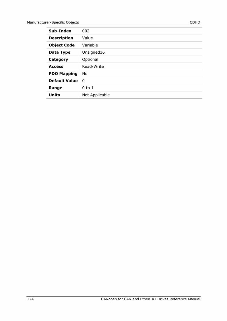
Manufacturer-Specific Objects CDHD
174 CANopen for CAN and EtherCAT Drives Reference Manual
Sub-Index 002
Description Value
Object Code Variable
Data Type Unsigned16
Category Optional
Access Read/Write
PDO Mapping No
Default Value 0
Range 0 to 1
Units Not Applicable
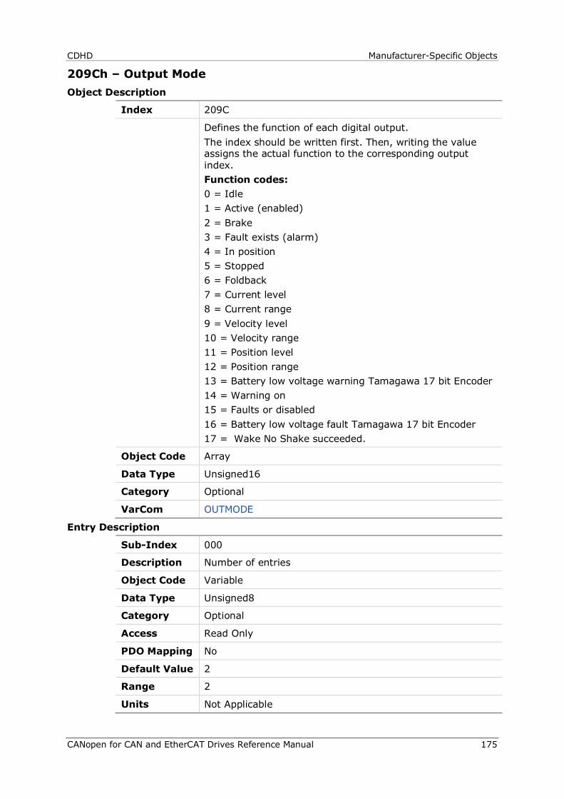
CDHD Manufacturer-Specific Objects
CANopen for CAN and EtherCAT Drives Reference Manual 175
209Ch – Output Mode Object Description
Index 209C
Defines the function of each digital output. The index should be written first. Then, writing the value assigns the actual function to the corresponding output index. Function codes: 0 = Idle 1 = Active (enabled) 2 = Brake 3 = Fault exists (alarm) 4 = In position 5 = Stopped 6 = Foldback 7 = Current level 8 = Current range 9 = Velocity level 10 = Velocity range 11 = Position level 12 = Position range 13 = Battery low voltage warning Tamagawa 17 bit Encoder 14 = Warning on 15 = Faults or disabled 16 = Battery low voltage fault Tamagawa 17 bit Encoder 17 = Wake No Shake succeeded.
Object Code Array
Data Type Unsigned16
Category Optional
VarCom OUTMODE
Entry Description
Sub-Index 000
Description Number of entries
Object Code Variable
Data Type Unsigned8
Category Optional
Access Read Only
PDO Mapping No
Default Value 2
Range 2
Units Not Applicable
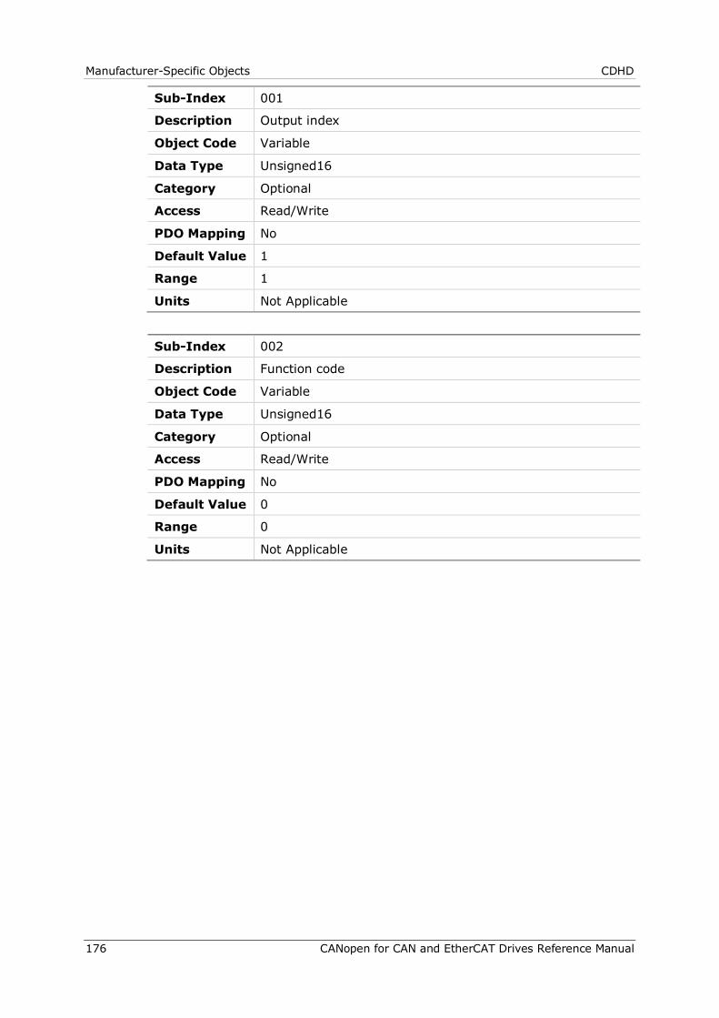
Manufacturer-Specific Objects CDHD
176 CANopen for CAN and EtherCAT Drives Reference Manual
Sub-Index 001
Description Output index
Object Code Variable
Data Type Unsigned16
Category Optional
Access Read/Write
PDO Mapping No
Default Value 1
Range 1
Units Not Applicable
Sub-Index 002
Description Function code
Object Code Variable
Data Type Unsigned16
Category Optional
Access Read/Write
PDO Mapping No
Default Value 0
Range 0
Units Not Applicable
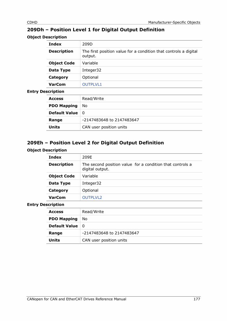
CDHD Manufacturer-Specific Objects
CANopen for CAN and EtherCAT Drives Reference Manual 177
209Dh – Position Level 1 for Digital Output Definition Object Description
Index 209D
Description The first position value for a condition that controls a digital output.
Object Code Variable
Data Type Integer32
Category Optional
VarCom OUTPLVL1
Entry Description
Access Read/Write
PDO Mapping No
Default Value 0
Range -2147483648 to 2147483647
Units CAN user position units
209Eh – Position Level 2 for Digital Output Definition Object Description
Index 209E
Description The second position value for a condition that controls a digital output.
Object Code Variable
Data Type Integer32
Category Optional
VarCom OUTPLVL2
Entry Description
Access Read/Write
PDO Mapping No
Default Value 0
Range -2147483648 to 2147483647
Units CAN user position units
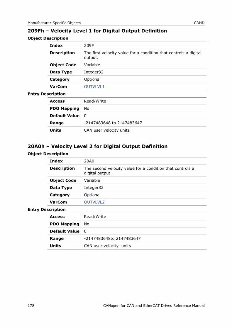
Manufacturer-Specific Objects CDHD
178 CANopen for CAN and EtherCAT Drives Reference Manual
209Fh – Velocity Level 1 for Digital Output Definition Object Description
Index 209F
Description The first velocity value for a condition that controls a digital output.
Object Code Variable
Data Type Integer32
Category Optional
VarCom OUTVLVL1
Entry Description
Access Read/Write
PDO Mapping No
Default Value 0
Range -2147483648 to 2147483647
Units CAN user velocity units
20A0h – Velocity Level 2 for Digital Output Definition Object Description
Index 20A0
Description The second velocity value for a condition that controls a digital output.
Object Code Variable
Data Type Integer32
Category Optional
VarCom OUTVLVL2
Entry Description
Access Read/Write
PDO Mapping No
Default Value 0
Range -2147483648to 2147483647
Units CAN user velocity units
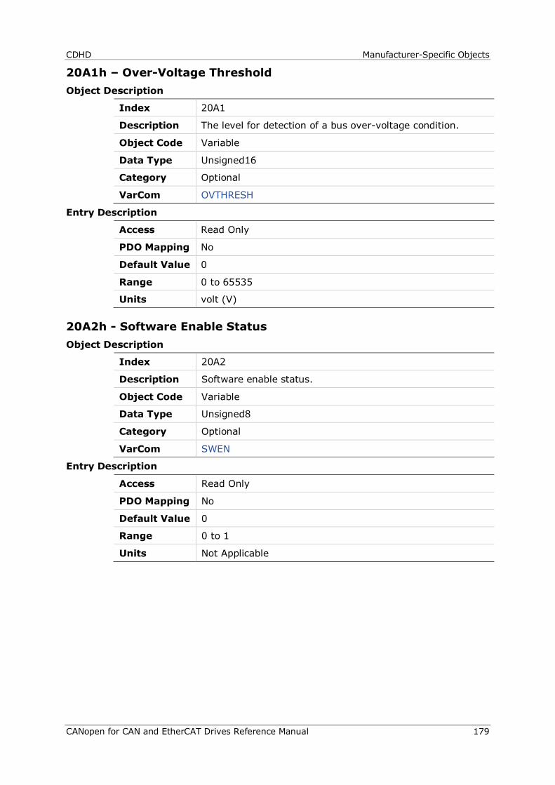
CDHD Manufacturer-Specific Objects
CANopen for CAN and EtherCAT Drives Reference Manual 179
20A1h – Over-Voltage Threshold Object Description
Index 20A1
Description The level for detection of a bus over-voltage condition.
Object Code Variable
Data Type Unsigned16
Category Optional
VarCom OVTHRESH
Entry Description
Access Read Only
PDO Mapping No
Default Value 0
Range 0 to 65535
Units volt (V)
20A2h - Software Enable Status Object Description
Index 20A2
Description Software enable status.
Object Code Variable
Data Type Unsigned8
Category Optional
VarCom SWEN
Entry Description
Access Read Only
PDO Mapping No
Default Value 0
Range 0 to 1
Units Not Applicable
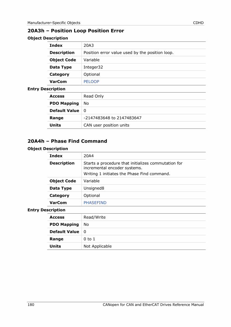
Manufacturer-Specific Objects CDHD
180 CANopen for CAN and EtherCAT Drives Reference Manual
20A3h – Position Loop Position Error Object Description
Index 20A3
Description Position error value used by the position loop.
Object Code Variable
Data Type Integer32
Category Optional
VarCom PELOOP
Entry Description
Access Read Only
PDO Mapping No
Default Value 0
Range -2147483648 to 2147483647
Units CAN user position units
20A4h – Phase Find Command Object Description
Index 20A4
Description Starts a procedure that initializes commutation for incremental encoder systems. Writing 1 initiates the Phase Find command.
Object Code Variable
Data Type Unsigned8
Category Optional
VarCom PHASEFIND
Entry Description
Access Read/Write
PDO Mapping No
Default Value 0
Range 0 to 1
Units Not Applicable
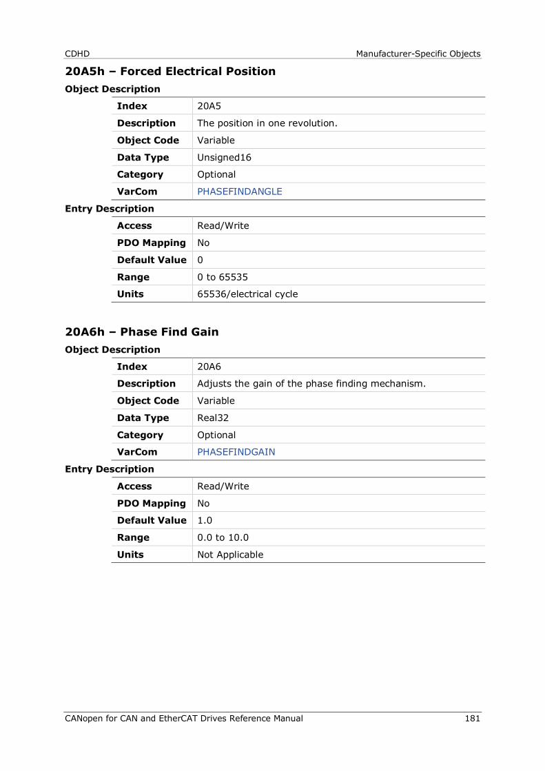
CDHD Manufacturer-Specific Objects
CANopen for CAN and EtherCAT Drives Reference Manual 181
20A5h – Forced Electrical Position Object Description
Index 20A5
Description The position in one revolution.
Object Code Variable
Data Type Unsigned16
Category Optional
VarCom PHASEFINDANGLE
Entry Description
Access Read/Write
PDO Mapping No
Default Value 0
Range 0 to 65535
Units 65536/electrical cycle
20A6h – Phase Find Gain Object Description
Index 20A6
Description Adjusts the gain of the phase finding mechanism.
Object Code Variable
Data Type Real32
Category Optional
VarCom PHASEFINDGAIN
Entry Description
Access Read/Write
PDO Mapping No
Default Value 1.0
Range 0.0 to 10.0
Units Not Applicable
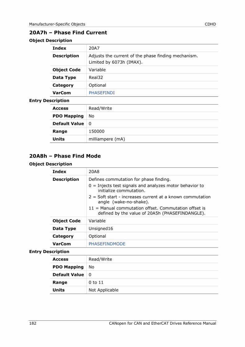
Manufacturer-Specific Objects CDHD
182 CANopen for CAN and EtherCAT Drives Reference Manual
20A7h – Phase Find Current Object Description
Index 20A7
Description Adjusts the current of the phase finding mechanism. Limited by 6073h (IMAX).
Object Code Variable
Data Type Real32
Category Optional
VarCom PHASEFINDI
Entry Description
Access Read/Write
PDO Mapping No
Default Value 0
Range 150000
Units milliampere (mA)
20A8h – Phase Find Mode Object Description
Index 20A8
Description Defines commutation for phase finding. 0 = Injects test signals and analyzes motor behavior to
initialize commutation. 2 = Soft start - increases current at a known commutation
angle (wake-no-shake). 11 = Manual commutation offset. Commutation offset is
defined by the value of 20A5h (PHASEFINDANGLE).
Object Code Variable
Data Type Unsigned16
Category Optional
VarCom PHASEFINDMODE
Entry Description
Access Read/Write
PDO Mapping No
Default Value 0
Range 0 to 11
Units Not Applicable
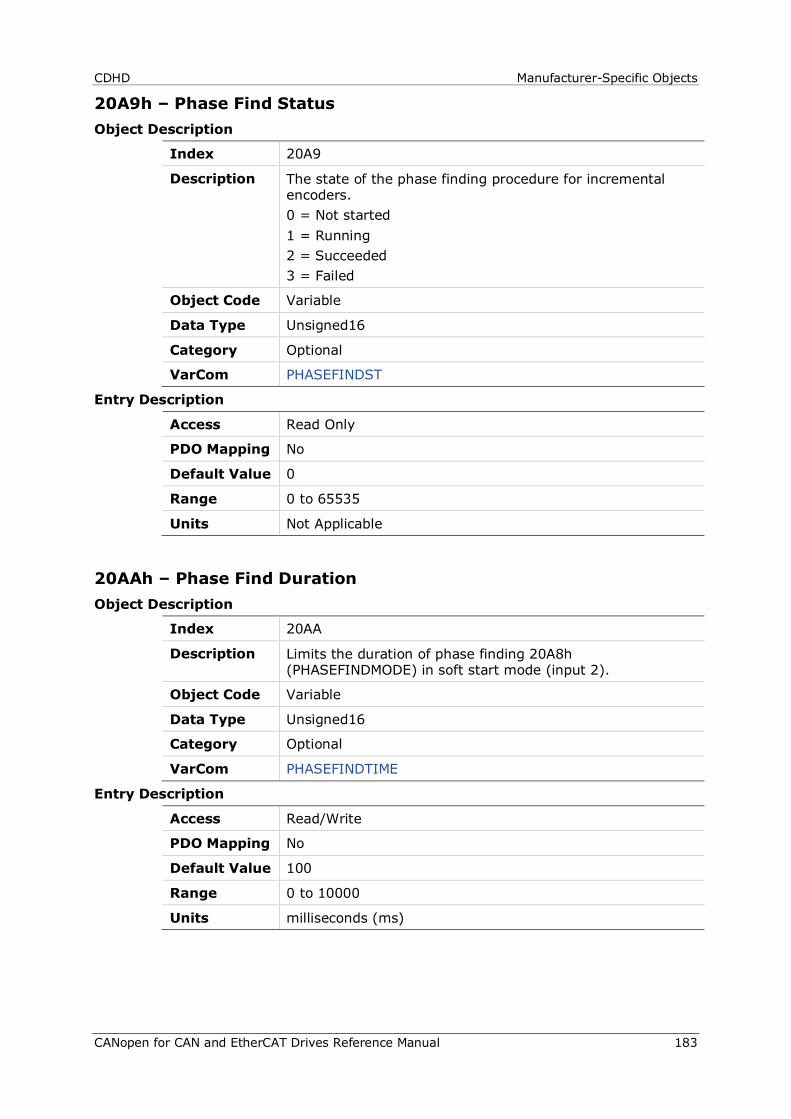
CDHD Manufacturer-Specific Objects
CANopen for CAN and EtherCAT Drives Reference Manual 183
20A9h – Phase Find Status Object Description
Index 20A9
Description The state of the phase finding procedure for incremental encoders. 0 = Not started 1 = Running 2 = Succeeded 3 = Failed
Object Code Variable
Data Type Unsigned16
Category Optional
VarCom PHASEFINDST
Entry Description
Access Read Only
PDO Mapping No
Default Value 0
Range 0 to 65535
Units Not Applicable
20AAh – Phase Find Duration Object Description
Index 20AA
Description Limits the duration of phase finding 20A8h (PHASEFINDMODE) in soft start mode (input 2).
Object Code Variable
Data Type Unsigned16
Category Optional
VarCom PHASEFINDTIME
Entry Description
Access Read/Write
PDO Mapping No
Default Value 100
Range 0 to 10000
Units milliseconds (ms)
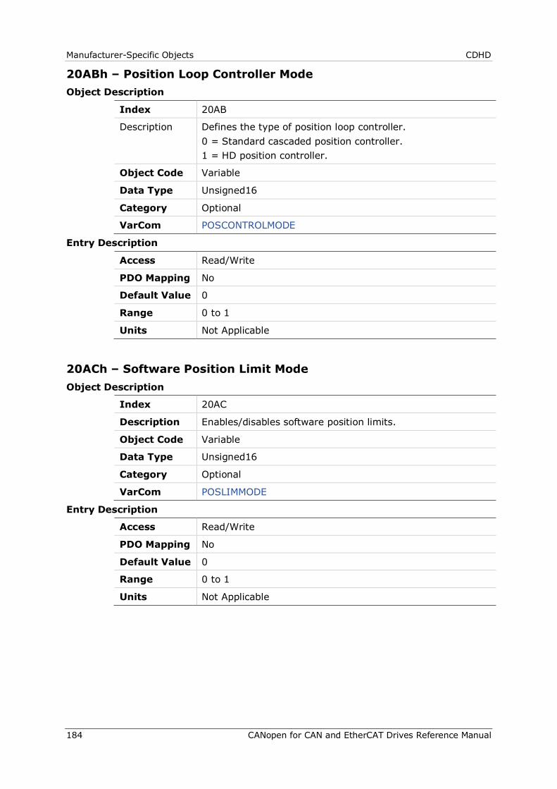
Manufacturer-Specific Objects CDHD
184 CANopen for CAN and EtherCAT Drives Reference Manual
20ABh – Position Loop Controller Mode Object Description
Index 20AB
Description Defines the type of position loop controller. 0 = Standard cascaded position controller. 1 = HD position controller.
Object Code Variable
Data Type Unsigned16
Category Optional
VarCom POSCONTROLMODE
Entry Description
Access Read/Write
PDO Mapping No
Default Value 0
Range 0 to 1
Units Not Applicable
20ACh – Software Position Limit Mode Object Description
Index 20AC
Description Enables/disables software position limits.
Object Code Variable
Data Type Unsigned16
Category Optional
VarCom POSLIMMODE
Entry Description
Access Read/Write
PDO Mapping No
Default Value 0
Range 0 to 1
Units Not Applicable
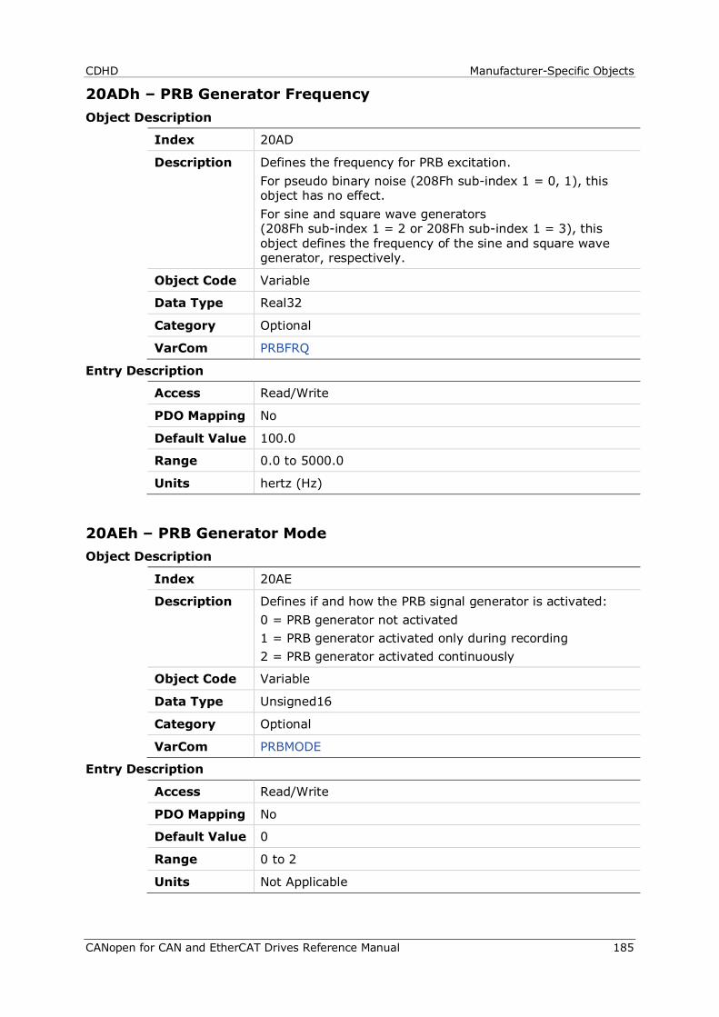
CDHD Manufacturer-Specific Objects
CANopen for CAN and EtherCAT Drives Reference Manual 185
20ADh – PRB Generator Frequency Object Description
Index 20AD
Description Defines the frequency for PRB excitation. For pseudo binary noise (208Fh sub-index 1 = 0, 1), this object has no effect. For sine and square wave generators (208Fh sub-index 1 = 2 or 208Fh sub-index 1 = 3), this object defines the frequency of the sine and square wave generator, respectively.
Object Code Variable
Data Type Real32
Category Optional
VarCom PRBFRQ
Entry Description
Access Read/Write
PDO Mapping No
Default Value 100.0
Range 0.0 to 5000.0
Units hertz (Hz)
20AEh – PRB Generator Mode Object Description
Index 20AE
Description Defines if and how the PRB signal generator is activated: 0 = PRB generator not activated 1 = PRB generator activated only during recording 2 = PRB generator activated continuously
Object Code Variable
Data Type Unsigned16
Category Optional
VarCom PRBMODE
Entry Description
Access Read/Write
PDO Mapping No
Default Value 0
Range 0 to 2
Units Not Applicable
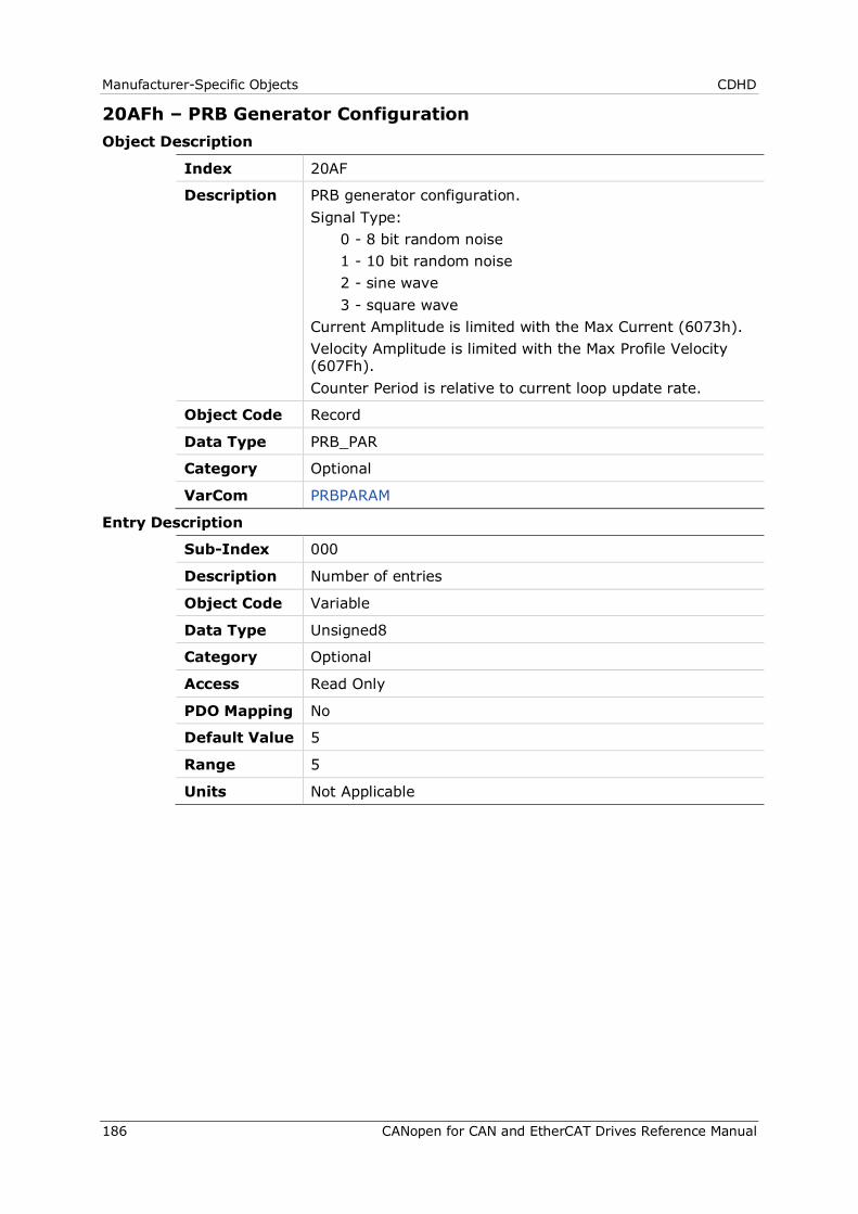
Manufacturer-Specific Objects CDHD
186 CANopen for CAN and EtherCAT Drives Reference Manual
20AFh – PRB Generator Configuration Object Description
Index 20AF
Description PRB generator configuration. Signal Type: 0 - 8 bit random noise 1 - 10 bit random noise 2 - sine wave 3 - square wave Current Amplitude is limited with the Max Current (6073h). Velocity Amplitude is limited with the Max Profile Velocity (607Fh). Counter Period is relative to current loop update rate.
Object Code Record
Data Type PRB_PAR
Category Optional
VarCom PRBPARAM
Entry Description
Sub-Index 000
Description Number of entries
Object Code Variable
Data Type Unsigned8
Category Optional
Access Read Only
PDO Mapping No
Default Value 5
Range 5
Units Not Applicable
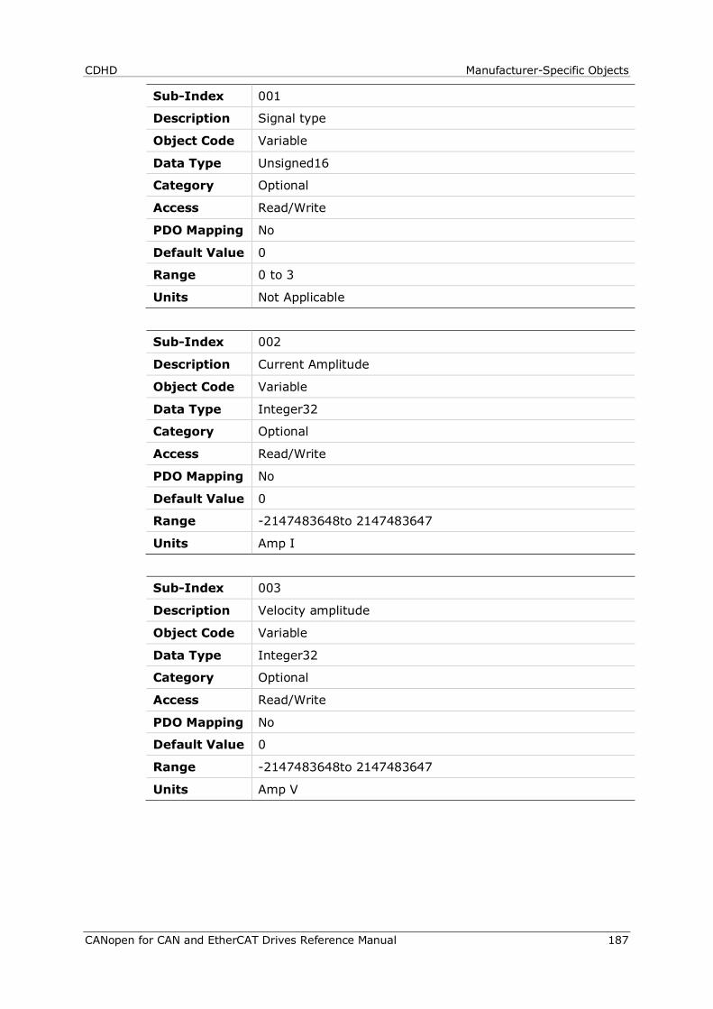
CDHD Manufacturer-Specific Objects
CANopen for CAN and EtherCAT Drives Reference Manual 187
Sub-Index 001
Description Signal type
Object Code Variable
Data Type Unsigned16
Category Optional
Access Read/Write
PDO Mapping No
Default Value 0
Range 0 to 3
Units Not Applicable
Sub-Index 002
Description Current Amplitude
Object Code Variable
Data Type Integer32
Category Optional
Access Read/Write
PDO Mapping No
Default Value 0
Range -2147483648to 2147483647
Units Amp I
Sub-Index 003
Description Velocity amplitude
Object Code Variable
Data Type Integer32
Category Optional
Access Read/Write
PDO Mapping No
Default Value 0
Range -2147483648to 2147483647
Units Amp V
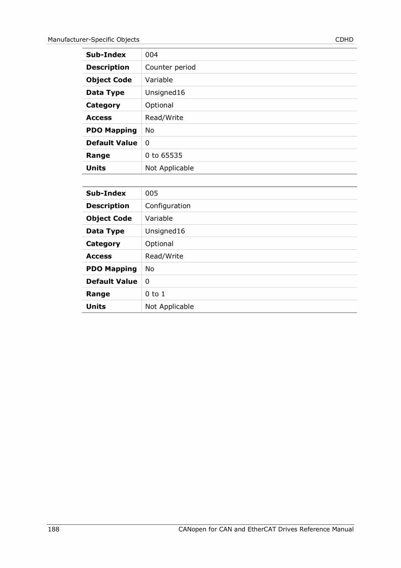
Manufacturer-Specific Objects CDHD
188 CANopen for CAN and EtherCAT Drives Reference Manual
Sub-Index 004
Description Counter period
Object Code Variable
Data Type Unsigned16
Category Optional
Access Read/Write
PDO Mapping No
Default Value 0
Range 0 to 65535
Units Not Applicable
Sub-Index 005
Description Configuration
Object Code Variable
Data Type Unsigned16
Category Optional
Access Read/Write
PDO Mapping No
Default Value 0
Range 0 to 1
Units Not Applicable
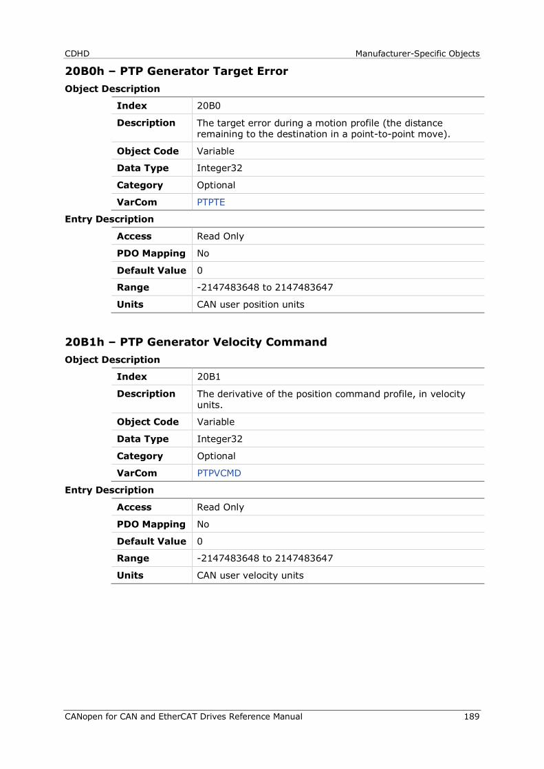
CDHD Manufacturer-Specific Objects
CANopen for CAN and EtherCAT Drives Reference Manual 189
20B0h – PTP Generator Target Error Object Description
Index 20B0
Description The target error during a motion profile (the distance remaining to the destination in a point-to-point move).
Object Code Variable
Data Type Integer32
Category Optional
VarCom PTPTE
Entry Description
Access Read Only
PDO Mapping No
Default Value 0
Range -2147483648 to 2147483647
Units CAN user position units
20B1h – PTP Generator Velocity Command Object Description
Index 20B1
Description The derivative of the position command profile, in velocity units.
Object Code Variable
Data Type Integer32
Category Optional
VarCom PTPVCMD
Entry Description
Access Read Only
PDO Mapping No
Default Value 0
Range -2147483648 to 2147483647
Units CAN user velocity units
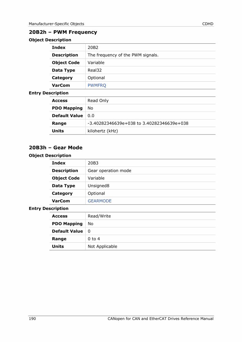
Manufacturer-Specific Objects CDHD
190 CANopen for CAN and EtherCAT Drives Reference Manual
20B2h – PWM Frequency Object Description
Index 20B2
Description The frequency of the PWM signals.
Object Code Variable
Data Type Real32
Category Optional
VarCom PWMFRQ
Entry Description
Access Read Only
PDO Mapping No
Default Value 0.0
Range -3.40282346639e+038 to 3.40282346639e+038
Units kilohertz (kHz)
20B3h – Gear Mode Object Description
Index 20B3
Description Gear operation mode
Object Code Variable
Data Type Unsigned8
Category Optional
VarCom GEARMODE
Entry Description
Access Read/Write
PDO Mapping No
Default Value 0
Range 0 to 4
Units Not Applicable
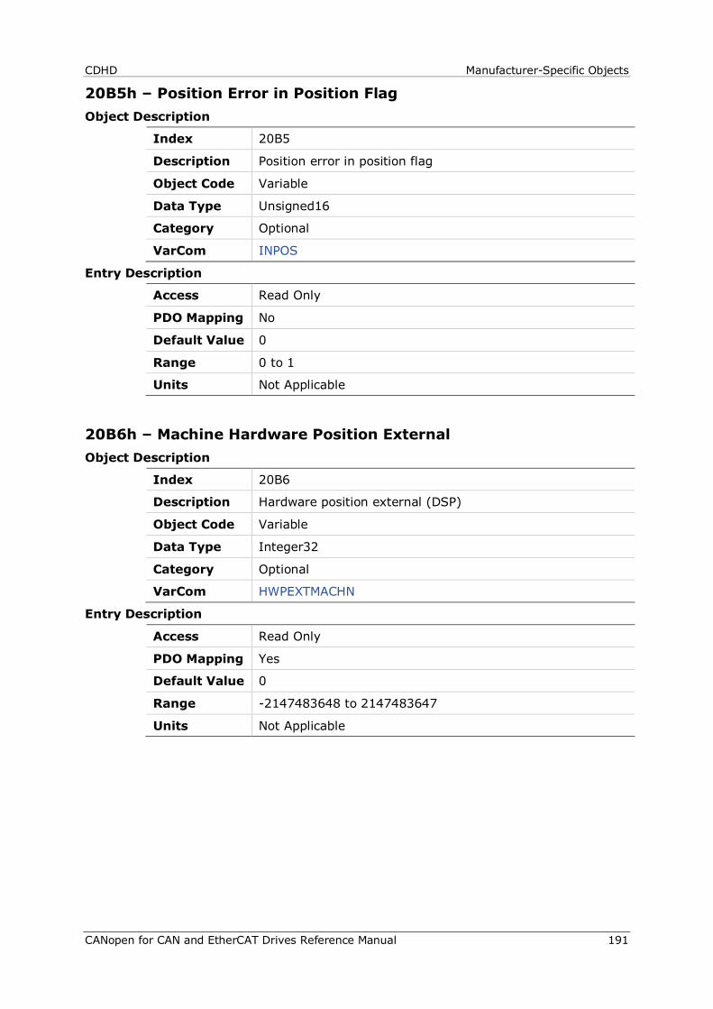
CDHD Manufacturer-Specific Objects
CANopen for CAN and EtherCAT Drives Reference Manual 191
20B5h – Position Error in Position Flag Object Description
Index 20B5
Description Position error in position flag
Object Code Variable
Data Type Unsigned16
Category Optional
VarCom INPOS
Entry Description
Access Read Only
PDO Mapping No
Default Value 0
Range 0 to 1
Units Not Applicable
20B6h – Machine Hardware Position External Object Description
Index 20B6
Description Hardware position external (DSP)
Object Code Variable
Data Type Integer32
Category Optional
VarCom HWPEXTMACHN
Entry Description
Access Read Only
PDO Mapping Yes
Default Value 0
Range -2147483648 to 2147483647
Units Not Applicable
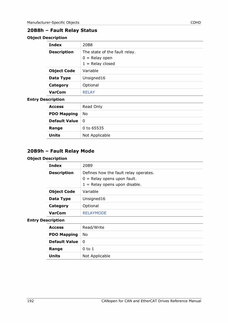
Manufacturer-Specific Objects CDHD
192 CANopen for CAN and EtherCAT Drives Reference Manual
20B8h – Fault Relay Status Object Description
Index 20B8
Description The state of the fault relay. 0 = Relay open 1 = Relay closed
Object Code Variable
Data Type Unsigned16
Category Optional
VarCom RELAY
Entry Description
Access Read Only
PDO Mapping No
Default Value 0
Range 0 to 65535
Units Not Applicable
20B9h – Fault Relay Mode Object Description
Index 20B9
Description Defines how the fault relay operates. 0 = Relay opens upon fault. 1 = Relay opens upon disable.
Object Code Variable
Data Type Unsigned16
Category Optional
VarCom RELAYMODE
Entry Description
Access Read/Write
PDO Mapping No
Default Value 0
Range 0 to 1
Units Not Applicable
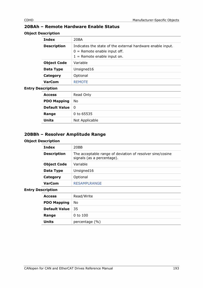
CDHD Manufacturer-Specific Objects
CANopen for CAN and EtherCAT Drives Reference Manual 193
20BAh – Remote Hardware Enable Status Object Description
Index 20BA
Description Indicates the state of the external hardware enable input. 0 = Remote enable input off. 1 = Remote enable input on.
Object Code Variable
Data Type Unsigned16
Category Optional
VarCom REMOTE
Entry Description
Access Read Only
PDO Mapping No
Default Value 0
Range 0 to 65535
Units Not Applicable
20BBh – Resolver Amplitude Range Object Description
Index 20BB
Description The acceptable range of deviation of resolver sine/cosine signals (as a percentage).
Object Code Variable
Data Type Unsigned16
Category Optional
VarCom RESAMPLRANGE
Entry Description
Access Read/Write
PDO Mapping No
Default Value 35
Range 0 to 100
Units percentage (%)

Manufacturer-Specific Objects CDHD
194 CANopen for CAN and EtherCAT Drives Reference Manual
20BCh – Resolver Conversion Bandwidth Object Description
Index 20BC
Description Resolver conversion bandwidth.
Object Code Variable
Data Type Unsigned16
Category Optional
VarCom RESBW
Entry Description
Access Read/Write
PDO Mapping No
Default Value 300
Range 200 to 800
Units hertz (Hz)
20BDh – Save/Load Status Object Description
Index 20BD
Description Save/load status
Object Code Variable
Data Type Unsigned8
Category Optional
VarCom Not Applicable
Entry Description
Access Read Only
PDO Mapping No
Default Value 0
Range 0 to 255
Units Not Applicable
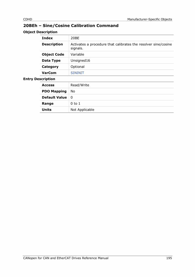
CDHD Manufacturer-Specific Objects
CANopen for CAN and EtherCAT Drives Reference Manual 195
20BEh – Sine/Cosine Calibration Command Object Description
Index 20BE
Description Activates a procedure that calibrates the resolver sine/cosine signals.
Object Code Variable
Data Type Unsigned16
Category Optional
VarCom SININIT
Entry Description
Access Read/Write
PDO Mapping No
Default Value 0
Range 0 to 1
Units Not Applicable
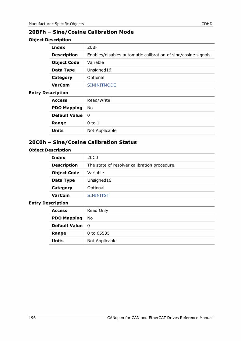
Manufacturer-Specific Objects CDHD
196 CANopen for CAN and EtherCAT Drives Reference Manual
20BFh – Sine/Cosine Calibration Mode Object Description
Index 20BF
Description Enables/disables automatic calibration of sine/cosine signals.
Object Code Variable
Data Type Unsigned16
Category Optional
VarCom SININITMODE
Entry Description
Access Read/Write
PDO Mapping No
Default Value 0
Range 0 to 1
Units Not Applicable
20C0h – Sine/Cosine Calibration Status Object Description
Index 20C0
Description The state of resolver calibration procedure.
Object Code Variable
Data Type Unsigned16
Category Optional
VarCom SININITST
Entry Description
Access Read Only
PDO Mapping No
Default Value 0
Range 0 to 65535
Units Not Applicable
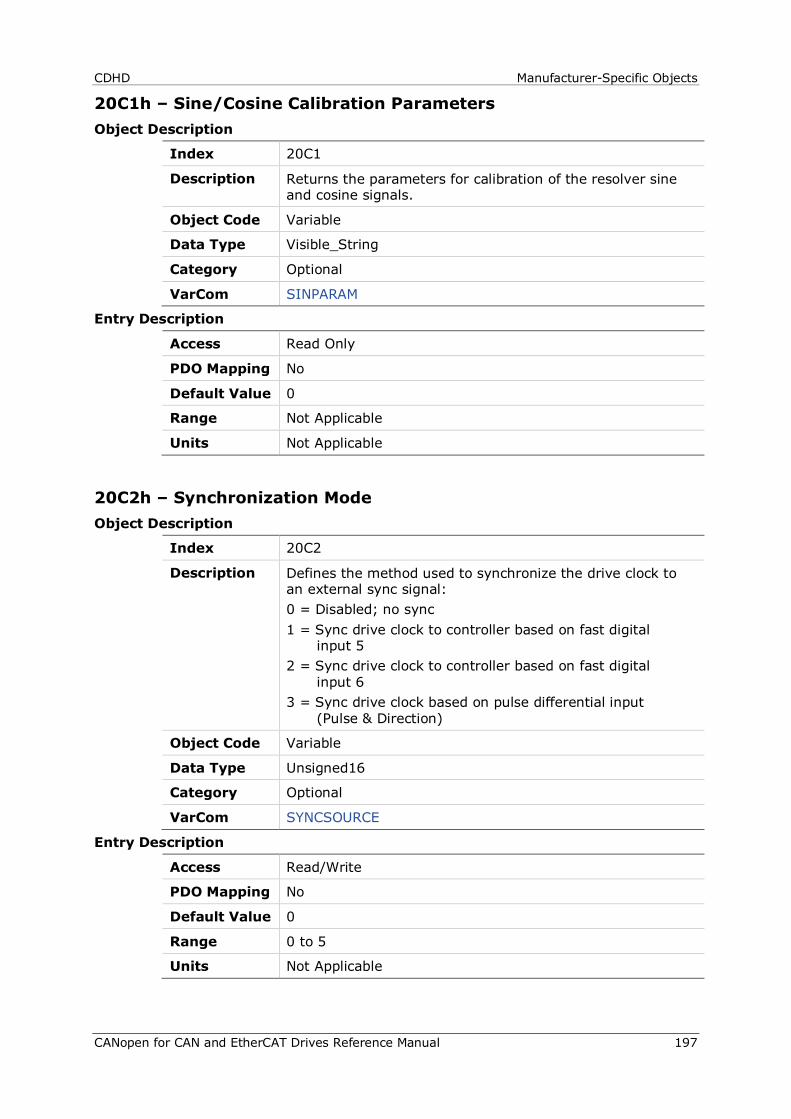
CDHD Manufacturer-Specific Objects
CANopen for CAN and EtherCAT Drives Reference Manual 197
20C1h – Sine/Cosine Calibration Parameters Object Description
Index 20C1
Description Returns the parameters for calibration of the resolver sine and cosine signals.
Object Code Variable
Data Type Visible_String
Category Optional
VarCom SINPARAM
Entry Description
Access Read Only
PDO Mapping No
Default Value 0
Range Not Applicable
Units Not Applicable
20C2h – Synchronization Mode Object Description
Index 20C2
Description Defines the method used to synchronize the drive clock to an external sync signal: 0 = Disabled; no sync 1 = Sync drive clock to controller based on fast digital
input 5 2 = Sync drive clock to controller based on fast digital
input 6 3 = Sync drive clock based on pulse differential input
(Pulse & Direction)
Object Code Variable
Data Type Unsigned16
Category Optional
VarCom SYNCSOURCE
Entry Description
Access Read/Write
PDO Mapping No
Default Value 0
Range 0 to 5
Units Not Applicable
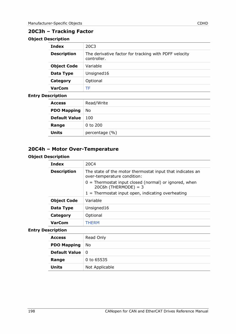
Manufacturer-Specific Objects CDHD
198 CANopen for CAN and EtherCAT Drives Reference Manual
20C3h – Tracking Factor Object Description
Index 20C3
Description The derivative factor for tracking with PDFF velocity controller.
Object Code Variable
Data Type Unsigned16
Category Optional
VarCom TF
Entry Description
Access Read/Write
PDO Mapping No
Default Value 100
Range 0 to 200
Units percentage (%)
20C4h – Motor Over-Temperature Object Description
Index 20C4
Description The state of the motor thermostat input that indicates an over-temperature condition: 0 = Thermostat input closed (normal) or ignored, when
20C6h (THERMODE) = 3 1 = Thermostat input open, indicating overheating
Object Code Variable
Data Type Unsigned16
Category Optional
VarCom THERM
Entry Description
Access Read Only
PDO Mapping No
Default Value 0
Range 0 to 65535
Units Not Applicable
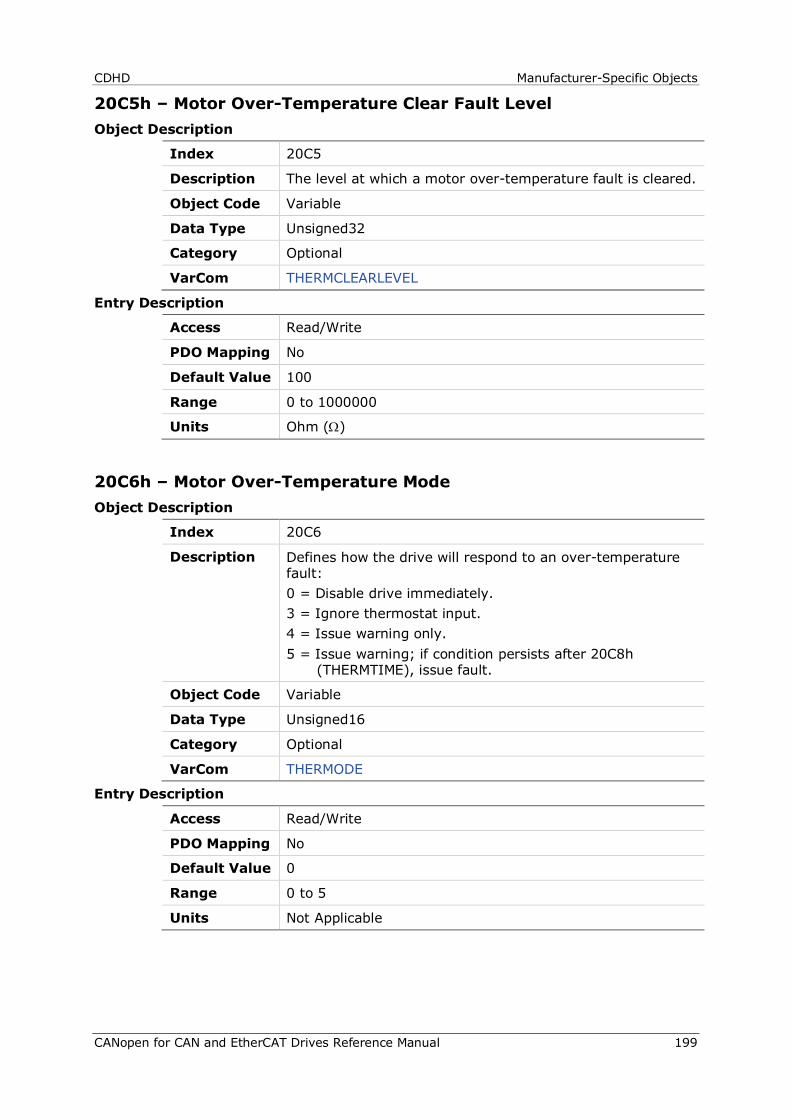
CDHD Manufacturer-Specific Objects
CANopen for CAN and EtherCAT Drives Reference Manual 199
20C5h – Motor Over-Temperature Clear Fault Level Object Description
Index 20C5
Description The level at which a motor over-temperature fault is cleared.
Object Code Variable
Data Type Unsigned32
Category Optional
VarCom THERMCLEARLEVEL
Entry Description
Access Read/Write
PDO Mapping No
Default Value 100
Range 0 to 1000000
Units Ohm (Ω)
20C6h – Motor Over-Temperature Mode Object Description
Index 20C6
Description Defines how the drive will respond to an over-temperature fault: 0 = Disable drive immediately. 3 = Ignore thermostat input. 4 = Issue warning only. 5 = Issue warning; if condition persists after 20C8h
(THERMTIME), issue fault.
Object Code Variable
Data Type Unsigned16
Category Optional
VarCom THERMODE
Entry Description
Access Read/Write
PDO Mapping No
Default Value 0
Range 0 to 5
Units Not Applicable
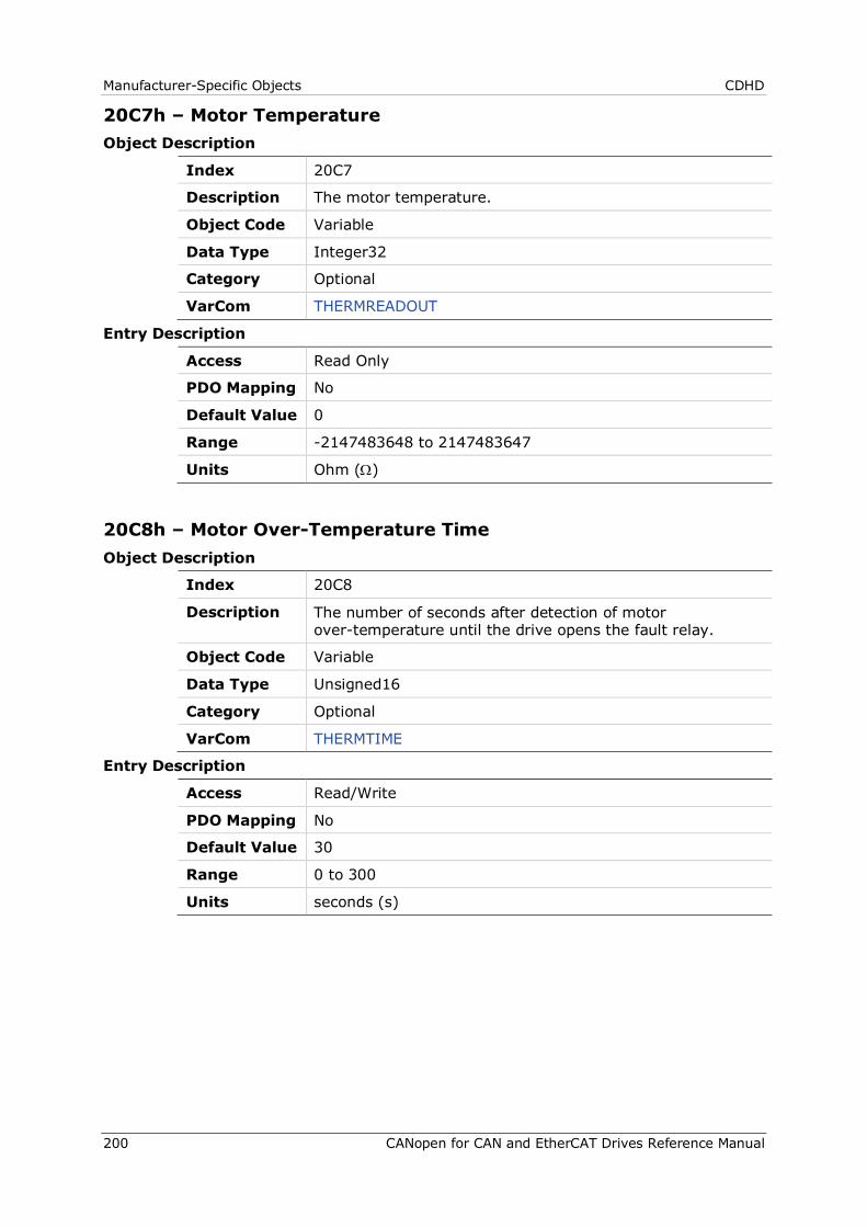
Manufacturer-Specific Objects CDHD
200 CANopen for CAN and EtherCAT Drives Reference Manual
20C7h – Motor Temperature Object Description
Index 20C7
Description The motor temperature.
Object Code Variable
Data Type Integer32
Category Optional
VarCom THERMREADOUT
Entry Description
Access Read Only
PDO Mapping No
Default Value 0
Range -2147483648 to 2147483647
Units Ohm (Ω)
20C8h – Motor Over-Temperature Time Object Description
Index 20C8
Description The number of seconds after detection of motor over-temperature until the drive opens the fault relay.
Object Code Variable
Data Type Unsigned16
Category Optional
VarCom THERMTIME
Entry Description
Access Read/Write
PDO Mapping No
Default Value 30
Range 0 to 300
Units seconds (s)
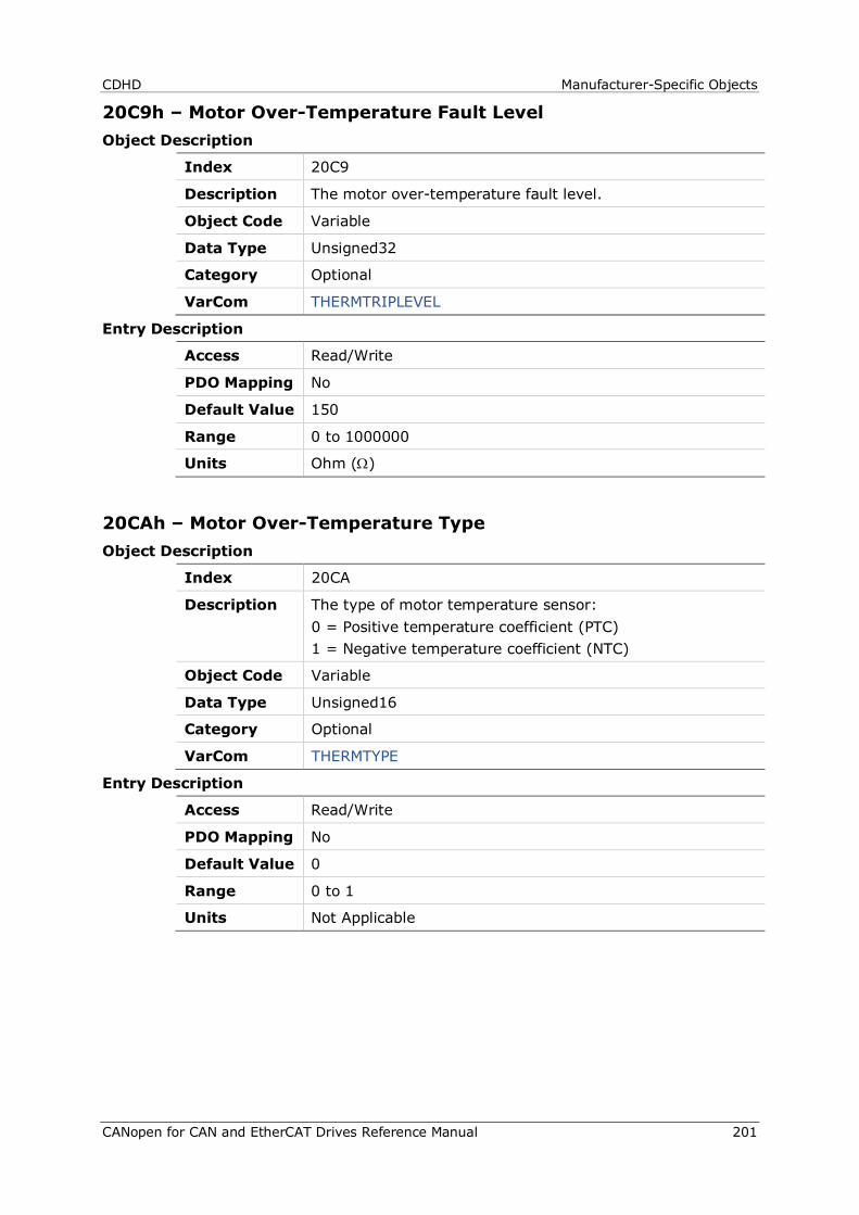
CDHD Manufacturer-Specific Objects
CANopen for CAN and EtherCAT Drives Reference Manual 201
20C9h – Motor Over-Temperature Fault Level Object Description
Index 20C9
Description The motor over-temperature fault level.
Object Code Variable
Data Type Unsigned32
Category Optional
VarCom THERMTRIPLEVEL
Entry Description
Access Read/Write
PDO Mapping No
Default Value 150
Range 0 to 1000000
Units Ohm (Ω)
20CAh – Motor Over-Temperature Type Object Description
Index 20CA
Description The type of motor temperature sensor: 0 = Positive temperature coefficient (PTC) 1 = Negative temperature coefficient (NTC)
Object Code Variable
Data Type Unsigned16
Category Optional
VarCom THERMTYPE
Entry Description
Access Read/Write
PDO Mapping No
Default Value 0
Range 0 to 1
Units Not Applicable

Manufacturer-Specific Objects CDHD
202 CANopen for CAN and EtherCAT Drives Reference Manual
20CBh – Tamagawa Multi-Turn Reset Object Description
Index 20CB
Description Resets the counter of a Tamagawa multi-turn encoder. Writing 01 initiates the command.
Object Code Variable
Data Type Unsigned8
Category Optional
VarCom TMTURNRESET
Entry Description
Access Read/Write
PDO Mapping No
Default Value 0
Range 0 to 1
Units Not Applicable
20CCh – Run Time Object Description
Index 20CC
Description The total elapsed run time of the drive since production (cannot be reset).
Object Code Variable
Data Type Visible_String
Category Optional
VarCom TRUN
Entry Description
Access Read Only
PDO Mapping No
Default Value 0
Range Not Applicable
Units Not Applicable
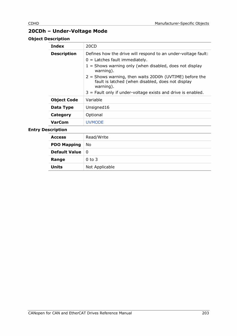
CDHD Manufacturer-Specific Objects
CANopen for CAN and EtherCAT Drives Reference Manual 203
20CDh – Under-Voltage Mode Object Description
Index 20CD
Description Defines how the drive will respond to an under-voltage fault: 0 = Latches fault immediately. 1 = Shows warning only (when disabled, does not display
warning). 2 = Shows warning, then waits 20D0h (UVTIME) before the
fault is latched (when disabled, does not display warning).
3 = Fault only if under-voltage exists and drive is enabled.
Object Code Variable
Data Type Unsigned16
Category Optional
VarCom UVMODE
Entry Description
Access Read/Write
PDO Mapping No
Default Value 0
Range 0 to 3
Units Not Applicable
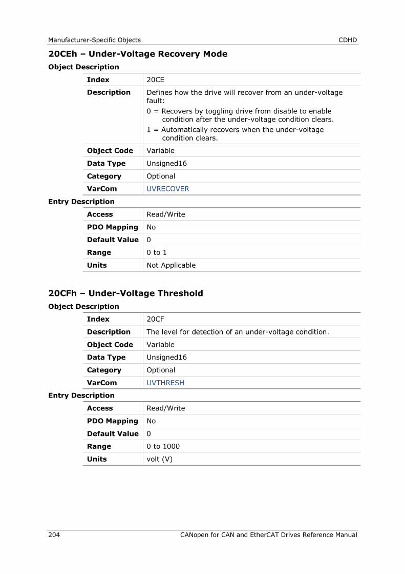
Manufacturer-Specific Objects CDHD
204 CANopen for CAN and EtherCAT Drives Reference Manual
20CEh – Under-Voltage Recovery Mode Object Description
Index 20CE
Description Defines how the drive will recover from an under-voltage fault: 0 = Recovers by toggling drive from disable to enable
condition after the under-voltage condition clears. 1 = Automatically recovers when the under-voltage
condition clears.
Object Code Variable
Data Type Unsigned16
Category Optional
VarCom UVRECOVER
Entry Description
Access Read/Write
PDO Mapping No
Default Value 0
Range 0 to 1
Units Not Applicable
20CFh – Under-Voltage Threshold Object Description
Index 20CF
Description The level for detection of an under-voltage condition.
Object Code Variable
Data Type Unsigned16
Category Optional
VarCom UVTHRESH
Entry Description
Access Read/Write
PDO Mapping No
Default Value 0
Range 0 to 1000
Units volt (V)
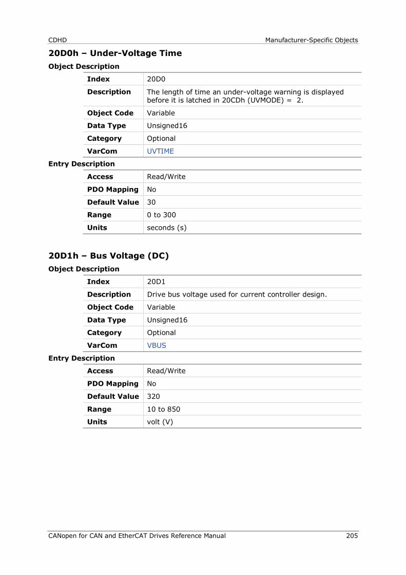
CDHD Manufacturer-Specific Objects
CANopen for CAN and EtherCAT Drives Reference Manual 205
20D0h – Under-Voltage Time Object Description
Index 20D0
Description The length of time an under-voltage warning is displayed before it is latched in 20CDh (UVMODE) = 2.
Object Code Variable
Data Type Unsigned16
Category Optional
VarCom UVTIME
Entry Description
Access Read/Write
PDO Mapping No
Default Value 30
Range 0 to 300
Units seconds (s)
20D1h – Bus Voltage (DC) Object Description
Index 20D1
Description Drive bus voltage used for current controller design.
Object Code Variable
Data Type Unsigned16
Category Optional
VarCom VBUS
Entry Description
Access Read/Write
PDO Mapping No
Default Value 320
Range 10 to 850
Units volt (V)
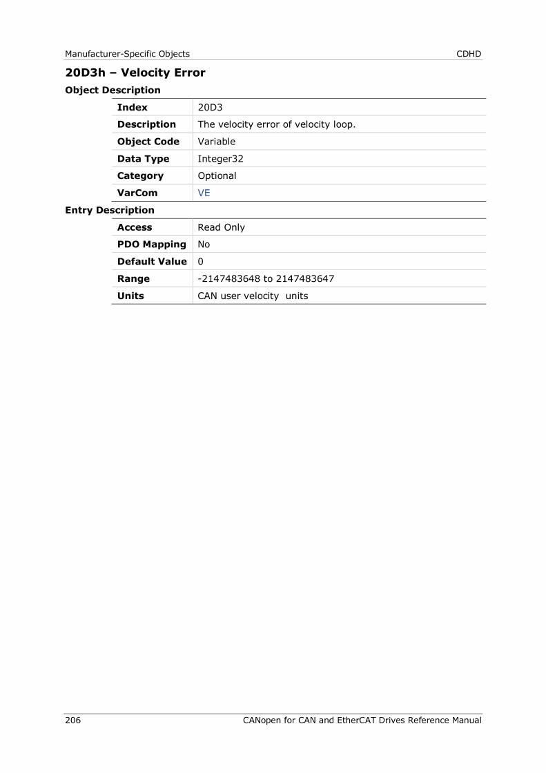
Manufacturer-Specific Objects CDHD
206 CANopen for CAN and EtherCAT Drives Reference Manual
20D3h – Velocity Error Object Description
Index 20D3
Description The velocity error of velocity loop.
Object Code Variable
Data Type Integer32
Category Optional
VarCom VE
Entry Description
Access Read Only
PDO Mapping No
Default Value 0
Range -2147483648 to 2147483647
Units CAN user velocity units
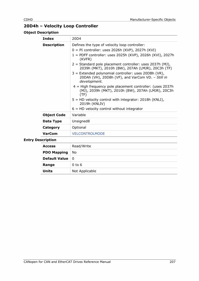
CDHD Manufacturer-Specific Objects
CANopen for CAN and EtherCAT Drives Reference Manual 207
20D4h – Velocity Loop Controller Object Description
Index 20D4
Description Defines the type of velocity loop controller: 0 = PI controller: uses 2026h (KVP), 2027h (KVI) 1 = PDFF controller: uses 2025h (KVP), 2026h (KVI), 2027h
(KVFR) 2 = Standard pole placement controller: uses 2037h (MJ),
2039h (MKT), 2010h (BW), 207Ah (LMJR), 20C3h (TF) 3 = Extended polynomial controller: uses 20DBh (VR),
20DAh (VH), 20D8h (VF), and VarCom VD. – Still in development.
4 = High frequency pole placement controller: (uses 2037h (MJ), 2039h (MKT), 2010h (BW), 207Ah (LMJR), 20C3h (TF)
5 = HD velocity control with integrator: 2018h (KNLI), 2019h (KNLIV)
6 = HD velocity control without integrator
Object Code Variable
Data Type Unsigned8
Category Optional
VarCom VELCONTROLMODE
Entry Description
Access Read/Write
PDO Mapping No
Default Value 0
Range 0 to 6
Units Not Applicable
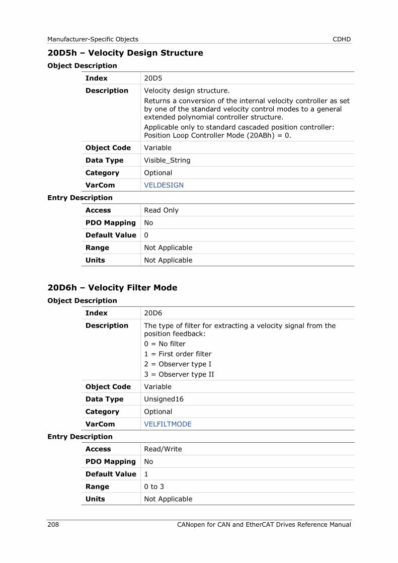
Manufacturer-Specific Objects CDHD
208 CANopen for CAN and EtherCAT Drives Reference Manual
20D5h – Velocity Design Structure Object Description
Index 20D5
Description Velocity design structure. Returns a conversion of the internal velocity controller as set by one of the standard velocity control modes to a general extended polynomial controller structure. Applicable only to standard cascaded position controller: Position Loop Controller Mode (20ABh) = 0.
Object Code Variable
Data Type Visible_String
Category Optional
VarCom VELDESIGN
Entry Description
Access Read Only
PDO Mapping No
Default Value 0
Range Not Applicable
Units Not Applicable
20D6h – Velocity Filter Mode Object Description
Index 20D6
Description The type of filter for extracting a velocity signal from the position feedback: 0 = No filter 1 = First order filter 2 = Observer type I 3 = Observer type II
Object Code Variable
Data Type Unsigned16
Category Optional
VarCom VELFILTMODE
Entry Description
Access Read/Write
PDO Mapping No
Default Value 1
Range 0 to 3
Units Not Applicable
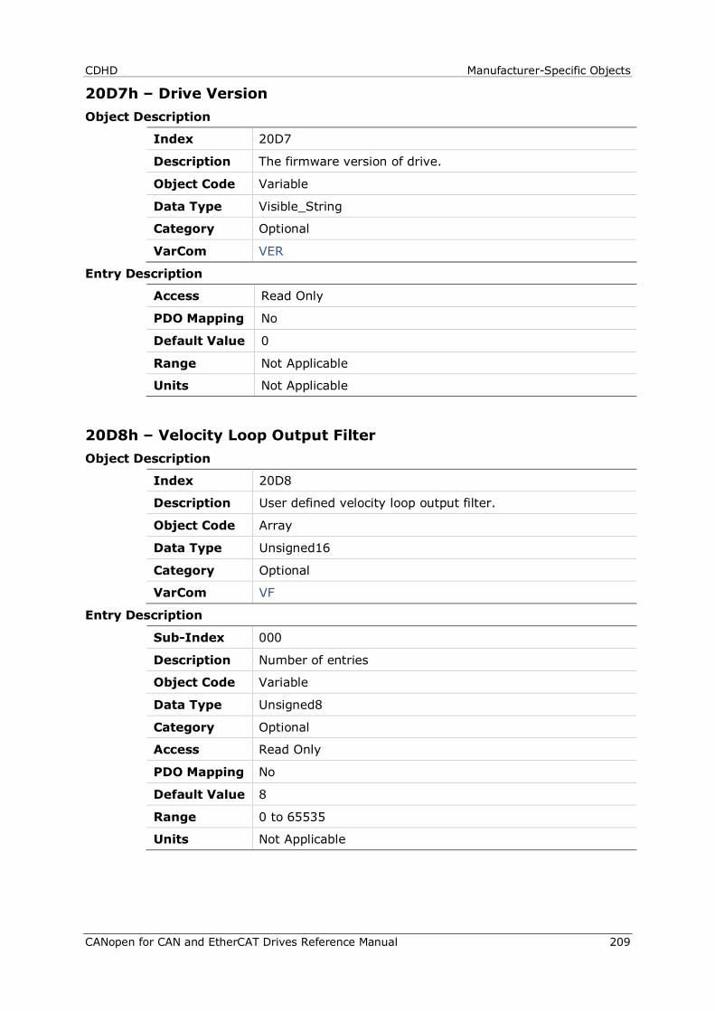
CDHD Manufacturer-Specific Objects
CANopen for CAN and EtherCAT Drives Reference Manual 209
20D7h – Drive Version Object Description
Index 20D7
Description The firmware version of drive.
Object Code Variable
Data Type Visible_String
Category Optional
VarCom VER
Entry Description
Access Read Only
PDO Mapping No
Default Value 0
Range Not Applicable
Units Not Applicable
20D8h – Velocity Loop Output Filter Object Description
Index 20D8
Description User defined velocity loop output filter.
Object Code Array
Data Type Unsigned16
Category Optional
VarCom VF
Entry Description
Sub-Index 000
Description Number of entries
Object Code Variable
Data Type Unsigned8
Category Optional
Access Read Only
PDO Mapping No
Default Value 8
Range 0 to 65535
Units Not Applicable
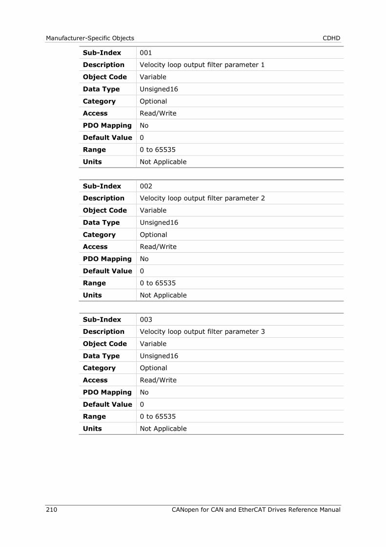
Manufacturer-Specific Objects CDHD
210 CANopen for CAN and EtherCAT Drives Reference Manual
Sub-Index 001
Description Velocity loop output filter parameter 1
Object Code Variable
Data Type Unsigned16
Category Optional
Access Read/Write
PDO Mapping No
Default Value 0
Range 0 to 65535
Units Not Applicable
Sub-Index 002
Description Velocity loop output filter parameter 2
Object Code Variable
Data Type Unsigned16
Category Optional
Access Read/Write
PDO Mapping No
Default Value 0
Range 0 to 65535
Units Not Applicable
Sub-Index 003
Description Velocity loop output filter parameter 3
Object Code Variable
Data Type Unsigned16
Category Optional
Access Read/Write
PDO Mapping No
Default Value 0
Range 0 to 65535
Units Not Applicable
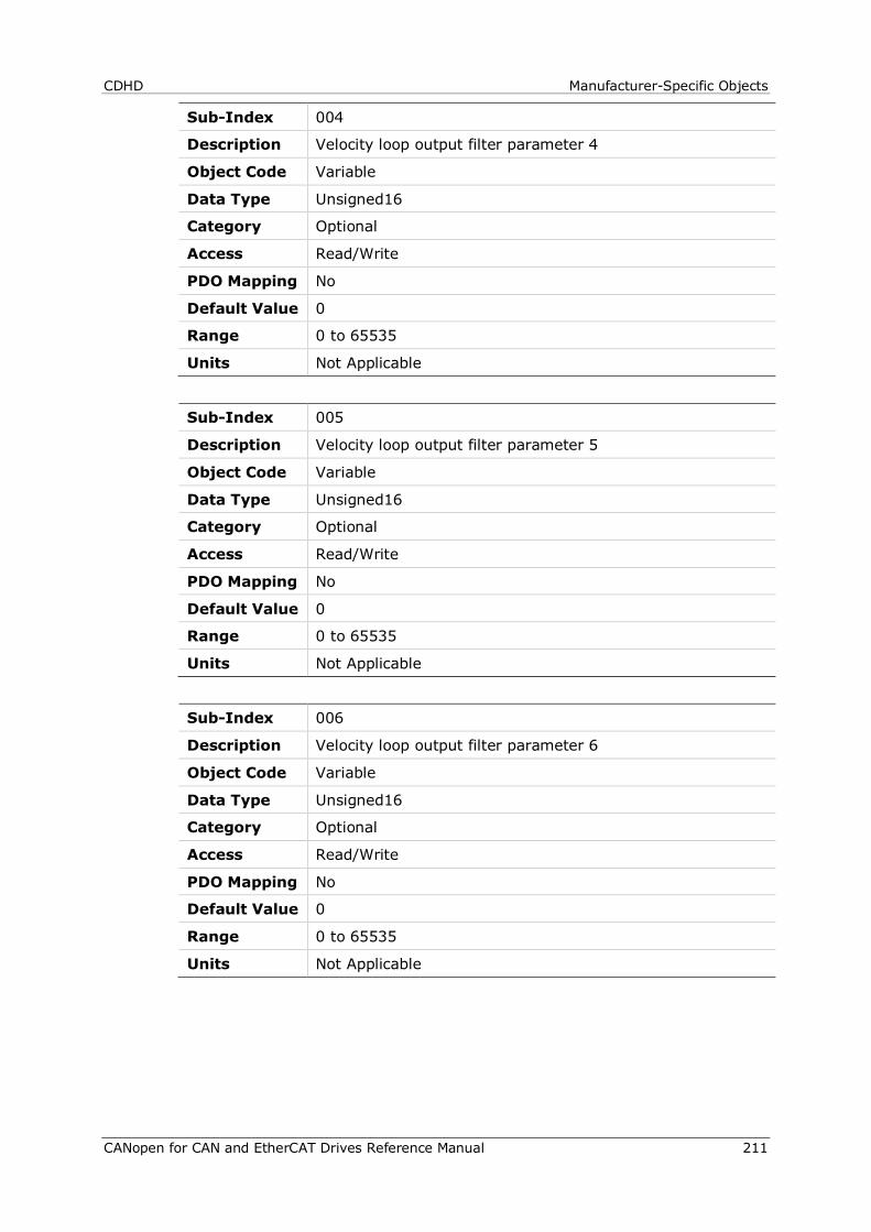
CDHD Manufacturer-Specific Objects
CANopen for CAN and EtherCAT Drives Reference Manual 211
Sub-Index 004
Description Velocity loop output filter parameter 4
Object Code Variable
Data Type Unsigned16
Category Optional
Access Read/Write
PDO Mapping No
Default Value 0
Range 0 to 65535
Units Not Applicable
Sub-Index 005
Description Velocity loop output filter parameter 5
Object Code Variable
Data Type Unsigned16
Category Optional
Access Read/Write
PDO Mapping No
Default Value 0
Range 0 to 65535
Units Not Applicable
Sub-Index 006
Description Velocity loop output filter parameter 6
Object Code Variable
Data Type Unsigned16
Category Optional
Access Read/Write
PDO Mapping No
Default Value 0
Range 0 to 65535
Units Not Applicable
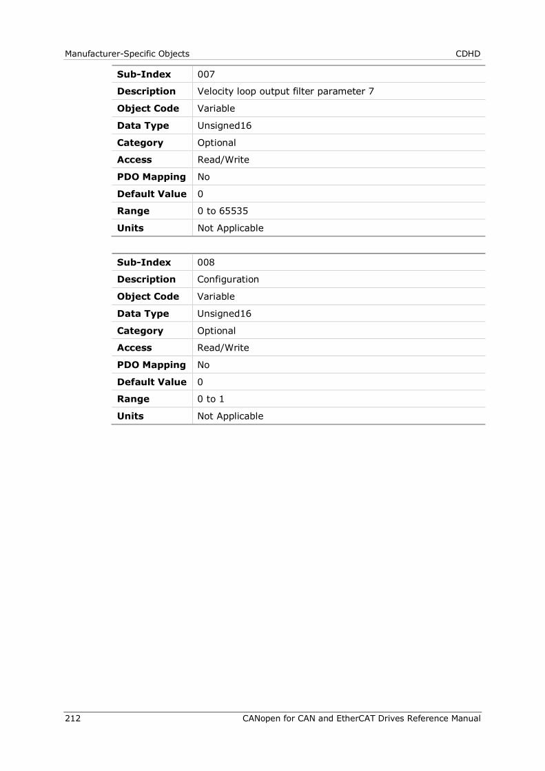
Manufacturer-Specific Objects CDHD
212 CANopen for CAN and EtherCAT Drives Reference Manual
Sub-Index 007
Description Velocity loop output filter parameter 7
Object Code Variable
Data Type Unsigned16
Category Optional
Access Read/Write
PDO Mapping No
Default Value 0
Range 0 to 65535
Units Not Applicable
Sub-Index 008
Description Configuration
Object Code Variable
Data Type Unsigned16
Category Optional
Access Read/Write
PDO Mapping No
Default Value 0
Range 0 to 1
Units Not Applicable
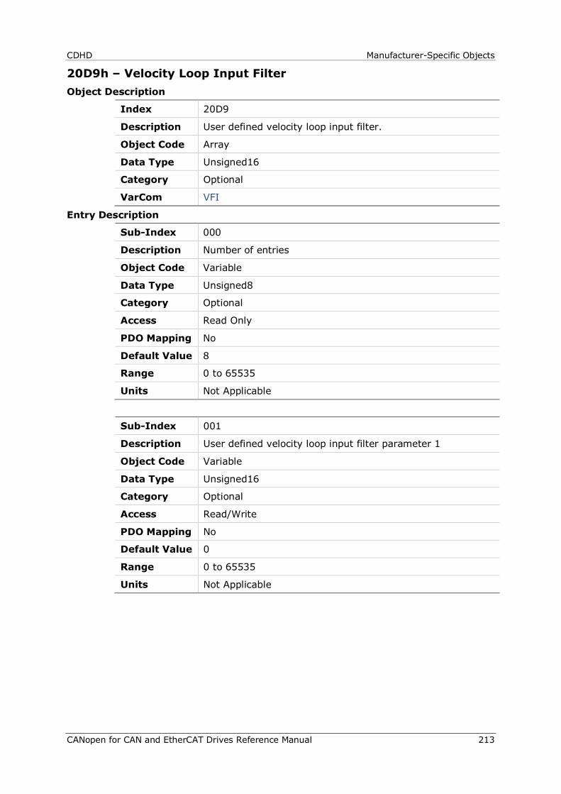
CDHD Manufacturer-Specific Objects
CANopen for CAN and EtherCAT Drives Reference Manual 213
20D9h – Velocity Loop Input Filter Object Description
Index 20D9
Description User defined velocity loop input filter.
Object Code Array
Data Type Unsigned16
Category Optional
VarCom VFI
Entry Description
Sub-Index 000
Description Number of entries
Object Code Variable
Data Type Unsigned8
Category Optional
Access Read Only
PDO Mapping No
Default Value 8
Range 0 to 65535
Units Not Applicable
Sub-Index 001
Description User defined velocity loop input filter parameter 1
Object Code Variable
Data Type Unsigned16
Category Optional
Access Read/Write
PDO Mapping No
Default Value 0
Range 0 to 65535
Units Not Applicable
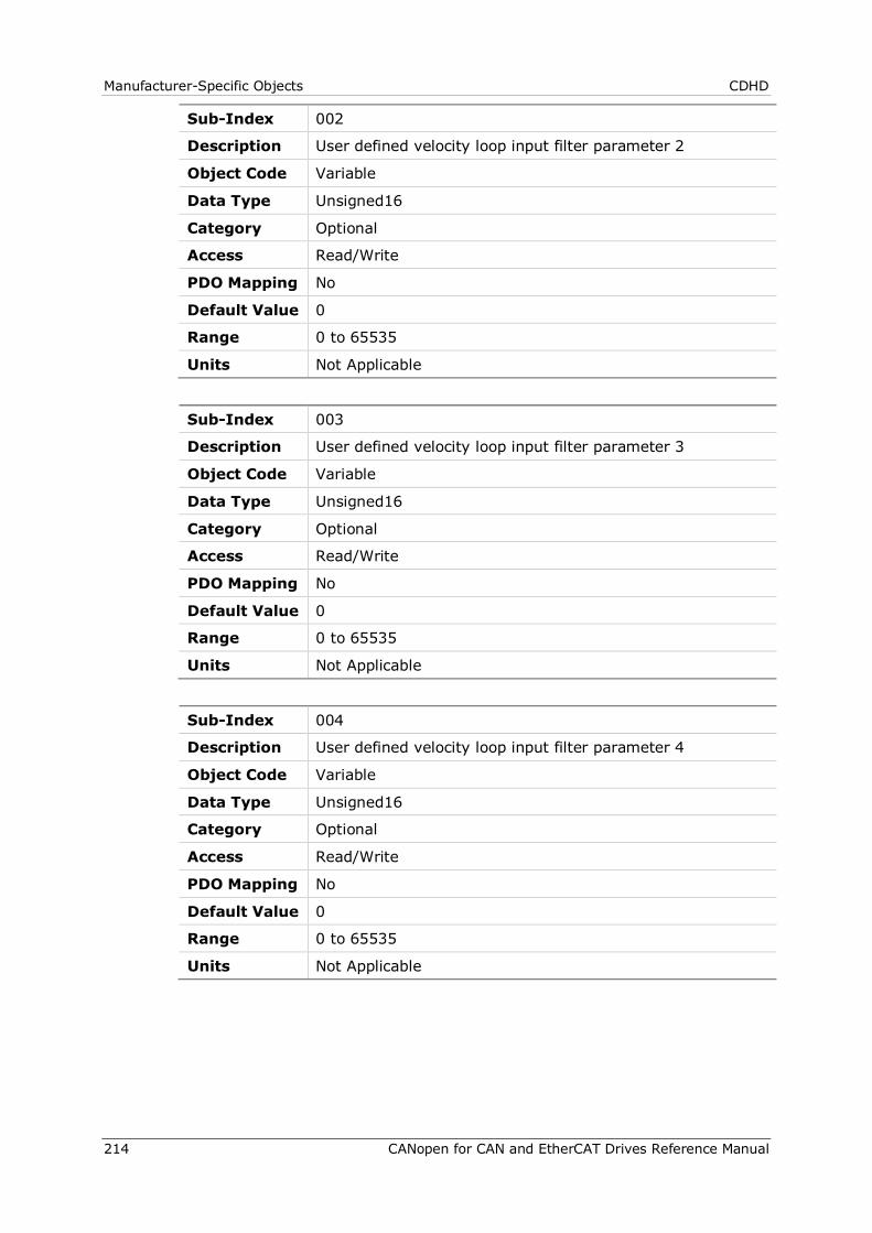
Manufacturer-Specific Objects CDHD
214 CANopen for CAN and EtherCAT Drives Reference Manual
Sub-Index 002
Description User defined velocity loop input filter parameter 2
Object Code Variable
Data Type Unsigned16
Category Optional
Access Read/Write
PDO Mapping No
Default Value 0
Range 0 to 65535
Units Not Applicable
Sub-Index 003
Description User defined velocity loop input filter parameter 3
Object Code Variable
Data Type Unsigned16
Category Optional
Access Read/Write
PDO Mapping No
Default Value 0
Range 0 to 65535
Units Not Applicable
Sub-Index 004
Description User defined velocity loop input filter parameter 4
Object Code Variable
Data Type Unsigned16
Category Optional
Access Read/Write
PDO Mapping No
Default Value 0
Range 0 to 65535
Units Not Applicable
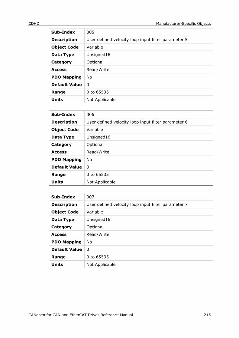
CDHD Manufacturer-Specific Objects
CANopen for CAN and EtherCAT Drives Reference Manual 215
Sub-Index 005
Description User defined velocity loop input filter parameter 5
Object Code Variable
Data Type Unsigned16
Category Optional
Access Read/Write
PDO Mapping No
Default Value 0
Range 0 to 65535
Units Not Applicable
Sub-Index 006
Description User defined velocity loop input filter parameter 6
Object Code Variable
Data Type Unsigned16
Category Optional
Access Read/Write
PDO Mapping No
Default Value 0
Range 0 to 65535
Units Not Applicable
Sub-Index 007
Description User defined velocity loop input filter parameter 7
Object Code Variable
Data Type Unsigned16
Category Optional
Access Read/Write
PDO Mapping No
Default Value 0
Range 0 to 65535
Units Not Applicable
Manufacturer-Specific Objects CDHD
216 CANopen for CAN and EtherCAT Drives Reference Manual
Sub-Index 008
Description Configuration
Object Code Variable
Data Type Unsigned16
Category Optional
Access Read/Write
PDO Mapping No
Default Value 0
Range 0 to 1
Units Not Applicable
20DAh – Advanced Pole Placement H Polynomial Object Description
Index 20DA
Description Advanced Pole Placement H Polynomial
Object Code Array
Data Type Unsigned16
Category Optional
VarCom VH
Entry Description
Sub-Index 000
Description Number of entries
Object Code Variable
Data Type Unsigned8
Category Optional
Access Read Only
PDO Mapping No
Default Value 13
Range 0 to 65535
Units Not Applicable
CDHD Manufacturer-Specific Objects
CANopen for CAN and EtherCAT Drives Reference Manual 217
Sub-Index 001
Description Advanced pole placement H polynomial parameter 1
Object Code Variable
Data Type Unsigned16
Category Optional
Access Read/Write
PDO Mapping No
Default Value 0
Range 0 to 65535
Units Not Applicable
Sub-Index 002
Description Advanced pole placement H polynomial parameter 2
Object Code Variable
Data Type Unsigned16
Category Optional
Access Read/Write
PDO Mapping No
Default Value 0
Range 0 to 65535
Units Not Applicable
Sub-Index 003
Description Advanced pole placement H polynomial parameter 3
Object Code Variable
Data Type Unsigned16
Category Optional
Access Read/Write
PDO Mapping No
Default Value 0
Range 0 to 65535
Units Not Applicable

Manufacturer-Specific Objects CDHD
218 CANopen for CAN and EtherCAT Drives Reference Manual
Sub-Index 004
Description Advanced pole placement H polynomial parameter 4
Object Code Variable
Data Type Unsigned16
Category Optional
Access Read/Write
PDO Mapping No
Default Value 0
Range 0 to 65535
Units Not Applicable
Sub-Index 005
Description Advanced pole placement H polynomial parameter 5
Object Code Variable
Data Type Unsigned16
Category Optional
Access Read/Write
PDO Mapping No
Default Value 0
Range 0 to 65535
Units Not Applicable
Sub-Index 006
Description Advanced pole placement H polynomial parameter 6
Object Code Variable
Data Type Unsigned16
Category Optional
Access Read/Write
PDO Mapping No
Default Value 0
Range 0 to 65535
Units Not Applicable
CDHD Manufacturer-Specific Objects
CANopen for CAN and EtherCAT Drives Reference Manual 219
Sub-Index 007
Description Advanced pole placement H polynomial parameter 7
Object Code Variable
Data Type Unsigned16
Category Optional
Access Read/Write
PDO Mapping No
Default Value 0
Range 0 to 65535
Units Not Applicable
Sub-Index 008
Description Advanced pole placement H polynomial parameter 8
Object Code Variable
Data Type Unsigned16
Category Optional
Access Read/Write
PDO Mapping No
Default Value 0
Range 0 to 65535
Units Not Applicable
Sub-Index 009
Description Advanced pole placement H polynomial parameter 9
Object Code Variable
Data Type Unsigned16
Category Optional
Access Read/Write
PDO Mapping No
Default Value 0
Range 0 to 65535
Units Not Applicable
Manufacturer-Specific Objects CDHD
220 CANopen for CAN and EtherCAT Drives Reference Manual
Sub-Index 010
Description Advanced pole placement H polynomial parameter 10
Object Code Variable
Data Type Unsigned16
Category Optional
Access Read/Write
PDO Mapping No
Default Value 0
Range 0 to 65535
Units Not Applicable
Sub-Index 011
Description Advanced pole placement H polynomial parameter 11
Object Code Variable
Data Type Unsigned16
Category Optional
Access Read/Write
PDO Mapping No
Default Value 0
Range 0 to 65535
Units Not Applicable
Sub-Index 012
Description Advanced pole placement H polynomial parameter 12
Object Code Variable
Data Type Unsigned16
Category Optional
Access Read/Write
PDO Mapping No
Default Value 0
Range 0 to 65535
Units Not Applicable
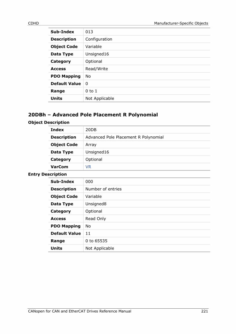
CDHD Manufacturer-Specific Objects
CANopen for CAN and EtherCAT Drives Reference Manual 221
Sub-Index 013
Description Configuration
Object Code Variable
Data Type Unsigned16
Category Optional
Access Read/Write
PDO Mapping No
Default Value 0
Range 0 to 1
Units Not Applicable
20DBh – Advanced Pole Placement R Polynomial Object Description
Index 20DB
Description Advanced Pole Placement R Polynomial
Object Code Array
Data Type Unsigned16
Category Optional
VarCom VR
Entry Description
Sub-Index 000
Description Number of entries
Object Code Variable
Data Type Unsigned8
Category Optional
Access Read Only
PDO Mapping No
Default Value 11
Range 0 to 65535
Units Not Applicable

Manufacturer-Specific Objects CDHD
222 CANopen for CAN and EtherCAT Drives Reference Manual
Sub-Index 001
Description Advanced pole placement R polynomial parameter 1
Object Code Variable
Data Type Unsigned16
Category Optional
Access Read/Write
PDO Mapping No
Default Value 0
Range 0 to 65535
Units Not Applicable
Sub-Index 002
Description Advanced pole placement R polynomial parameter 2
Object Code Variable
Data Type Unsigned16
Category Optional
Access Read/Write
PDO Mapping No
Default Value 0
Range 0 to 65535
Units Not Applicable
Sub-Index 003
Description Advanced pole placement R polynomial parameter 3
Object Code Variable
Data Type Unsigned16
Category Optional
Access Read/Write
PDO Mapping No
Default Value 0
Range 0 to 65535
Units Not Applicable

CDHD Manufacturer-Specific Objects
CANopen for CAN and EtherCAT Drives Reference Manual 223
Sub-Index 004
Description Advanced pole placement R polynomial parameter 4
Object Code Variable
Data Type Unsigned16
Category Optional
Access Read/Write
PDO Mapping No
Default Value 0
Range 0 to 65535
Units Not Applicable
Sub-Index 005
Description Advanced pole placement R polynomial parameter 5
Object Code Variable
Data Type Unsigned16
Category Optional
Access Read/Write
PDO Mapping No
Default Value 0
Range 0 to 65535
Units Not Applicable
Sub-Index 006
Description Advanced pole placement R polynomial parameter 6
Object Code Variable
Data Type Unsigned16
Category Optional
Access Read/Write
PDO Mapping No
Default Value 0
Range 0 to 65535
Units Not Applicable
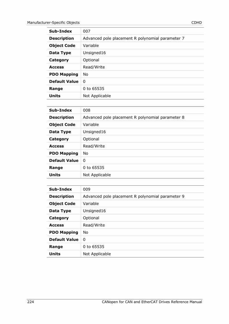
Manufacturer-Specific Objects CDHD
224 CANopen for CAN and EtherCAT Drives Reference Manual
Sub-Index 007
Description Advanced pole placement R polynomial parameter 7
Object Code Variable
Data Type Unsigned16
Category Optional
Access Read/Write
PDO Mapping No
Default Value 0
Range 0 to 65535
Units Not Applicable
Sub-Index 008
Description Advanced pole placement R polynomial parameter 8
Object Code Variable
Data Type Unsigned16
Category Optional
Access Read/Write
PDO Mapping No
Default Value 0
Range 0 to 65535
Units Not Applicable
Sub-Index 009
Description Advanced pole placement R polynomial parameter 9
Object Code Variable
Data Type Unsigned16
Category Optional
Access Read/Write
PDO Mapping No
Default Value 0
Range 0 to 65535
Units Not Applicable
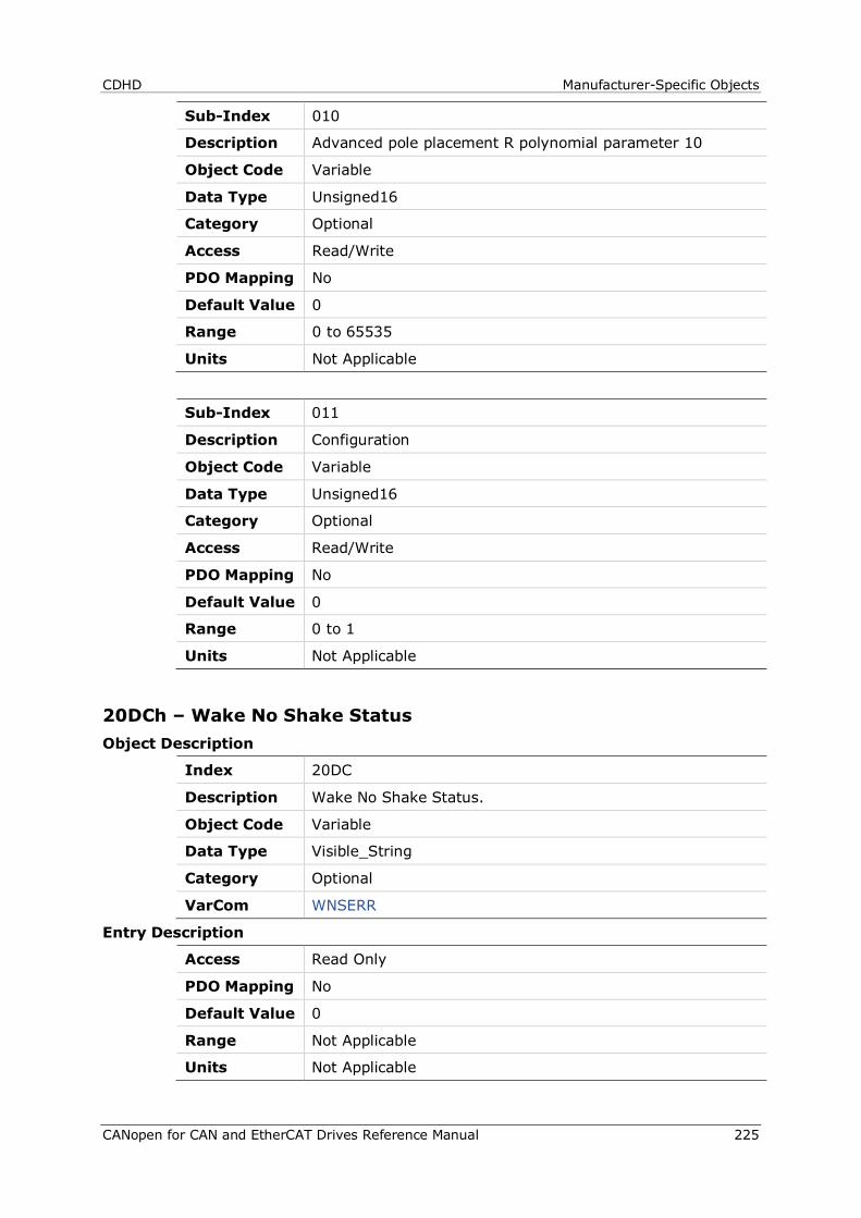
CDHD Manufacturer-Specific Objects
CANopen for CAN and EtherCAT Drives Reference Manual 225
Sub-Index 010
Description Advanced pole placement R polynomial parameter 10
Object Code Variable
Data Type Unsigned16
Category Optional
Access Read/Write
PDO Mapping No
Default Value 0
Range 0 to 65535
Units Not Applicable
Sub-Index 011
Description Configuration
Object Code Variable
Data Type Unsigned16
Category Optional
Access Read/Write
PDO Mapping No
Default Value 0
Range 0 to 1
Units Not Applicable
20DCh – Wake No Shake Status Object Description
Index 20DC
Description Wake No Shake Status.
Object Code Variable
Data Type Visible_String
Category Optional
VarCom WNSERR
Entry Description
Access Read Only
PDO Mapping No
Default Value 0
Range Not Applicable
Units Not Applicable
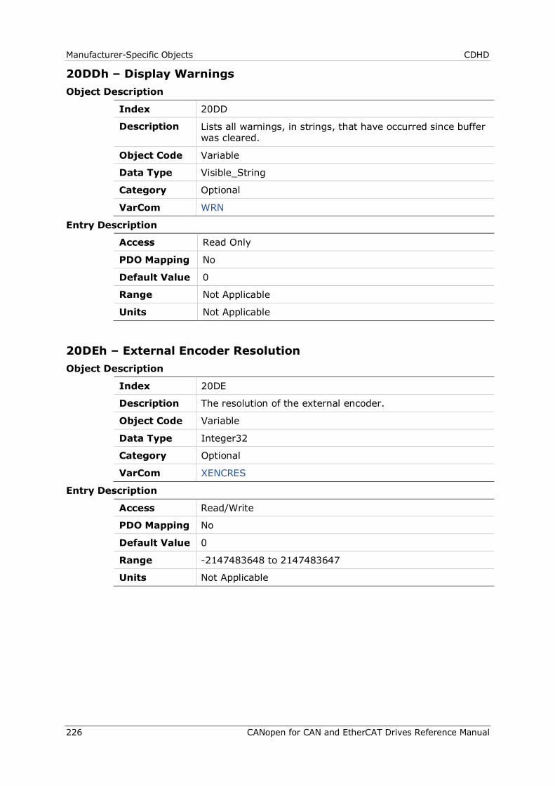
Manufacturer-Specific Objects CDHD
226 CANopen for CAN and EtherCAT Drives Reference Manual
20DDh – Display Warnings Object Description
Index 20DD
Description Lists all warnings, in strings, that have occurred since buffer was cleared.
Object Code Variable
Data Type Visible_String
Category Optional
VarCom WRN
Entry Description
Access Read Only
PDO Mapping No
Default Value 0
Range Not Applicable
Units Not Applicable
20DEh – External Encoder Resolution Object Description
Index 20DE
Description The resolution of the external encoder.
Object Code Variable
Data Type Integer32
Category Optional
VarCom XENCRES
Entry Description
Access Read/Write
PDO Mapping No
Default Value 0
Range -2147483648 to 2147483647
Units Not Applicable
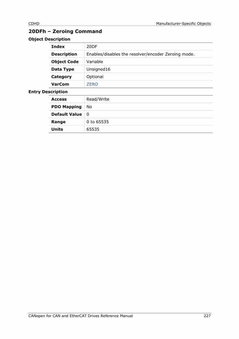
CDHD Manufacturer-Specific Objects
CANopen for CAN and EtherCAT Drives Reference Manual 227
20DFh – Zeroing Command Object Description
Index 20DF
Description Enables/disables the resolver/encoder Zeroing mode.
Object Code Variable
Data Type Unsigned16
Category Optional
VarCom ZERO
Entry Description
Access Read/Write
PDO Mapping No
Default Value 0
Range 0 to 65535
Units 65535
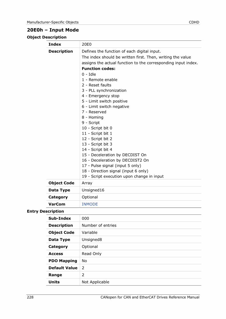
Manufacturer-Specific Objects CDHD
228 CANopen for CAN and EtherCAT Drives Reference Manual
20E0h – Input Mode Object Description
Index 20E0
Description Defines the function of each digital input. The index should be written first. Then, writing the value assigns the actual function to the corresponding input index. Function codes: 0 - Idle 1 - Remote enable 2 - Reset faults 3 - PLL synchronization 4 - Emergency stop 5 - Limit switch positive 6 - Limit switch negative 7 - Reserved 8 - Homing 9 - Script 10 - Script bit 0 11 - Script bit 1 12 - Script bit 2 13 - Script bit 3 14 - Script bit 4 15 - Deceleration by DECDIST On 16 - Deceleration by DECDIST2 On 17 - Pulse signal (input 5 only) 18 - Direction signal (input 6 only) 19 - Script execution upon change in input
Object Code Array
Data Type Unsigned16
Category Optional
VarCom INMODE
Entry Description
Sub-Index 000
Description Number of entries
Object Code Variable
Data Type Unsigned8
Category Optional
Access Read Only
PDO Mapping No
Default Value 2
Range 2
Units Not Applicable
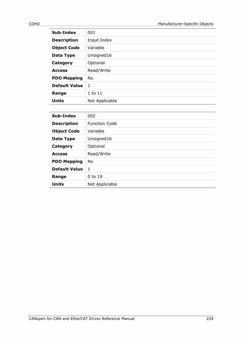
CDHD Manufacturer-Specific Objects
CANopen for CAN and EtherCAT Drives Reference Manual 229
Sub-Index 001
Description Input Index
Object Code Variable
Data Type Unsigned16
Category Optional
Access Read/Write
PDO Mapping No
Default Value 1
Range 1 to 11
Units Not Applicable
Sub-Index 002
Description Function Code
Object Code Variable
Data Type Unsigned16
Category Optional
Access Read/Write
PDO Mapping No
Default Value 1
Range 0 to 19
Units Not Applicable
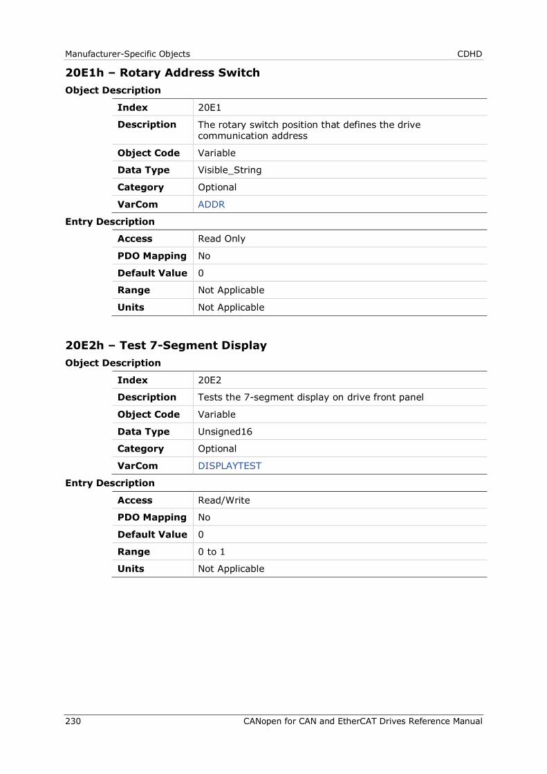
Manufacturer-Specific Objects CDHD
230 CANopen for CAN and EtherCAT Drives Reference Manual
20E1h – Rotary Address Switch Object Description
Index 20E1
Description The rotary switch position that defines the drive communication address
Object Code Variable
Data Type Visible_String
Category Optional
VarCom ADDR
Entry Description
Access Read Only
PDO Mapping No
Default Value 0
Range Not Applicable
Units Not Applicable
20E2h – Test 7-Segment Display Object Description
Index 20E2
Description Tests the 7-segment display on drive front panel
Object Code Variable
Data Type Unsigned16
Category Optional
VarCom DISPLAYTEST
Entry Description
Access Read/Write
PDO Mapping No
Default Value 0
Range 0 to 1
Units Not Applicable
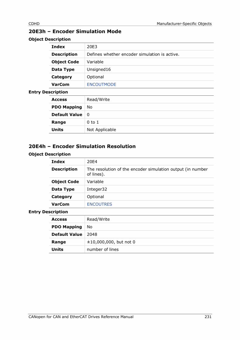
CDHD Manufacturer-Specific Objects
CANopen for CAN and EtherCAT Drives Reference Manual 231
20E3h – Encoder Simulation Mode Object Description
Index 20E3
Description Defines whether encoder simulation is active.
Object Code Variable
Data Type Unsigned16
Category Optional
VarCom ENCOUTMODE
Entry Description
Access Read/Write
PDO Mapping No
Default Value 0
Range 0 to 1
Units Not Applicable
20E4h – Encoder Simulation Resolution Object Description
Index 20E4
Description The resolution of the encoder simulation output (in number of lines).
Object Code Variable
Data Type Integer32
Category Optional
VarCom ENCOUTRES
Entry Description
Access Read/Write
PDO Mapping No
Default Value 2048
Range ±10,000,000, but not 0
Units number of lines
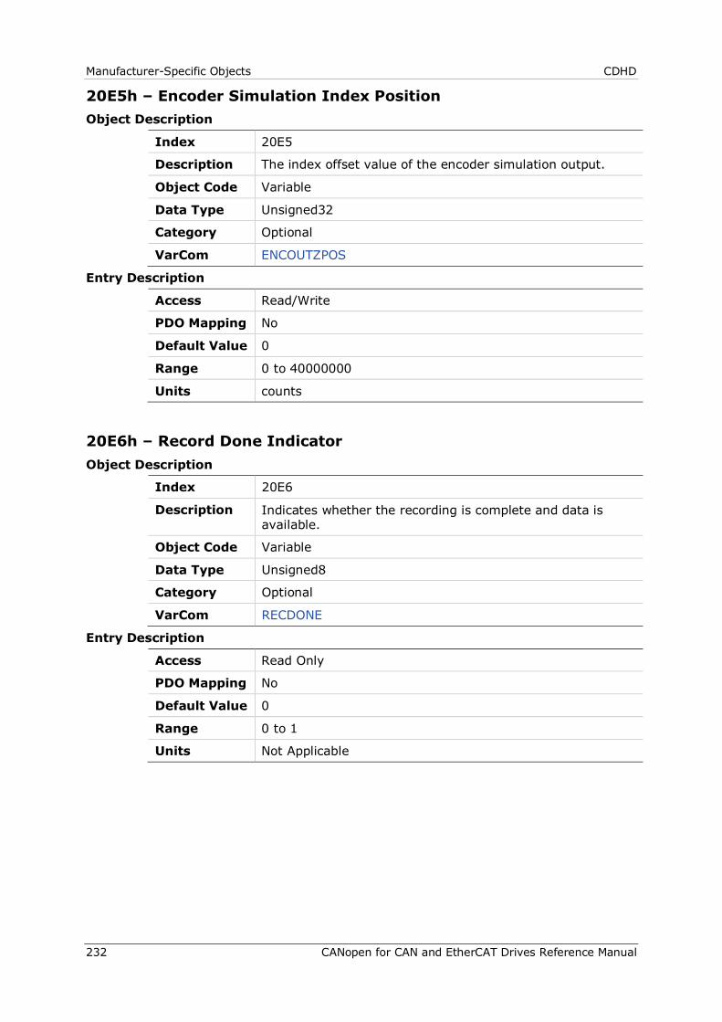
Manufacturer-Specific Objects CDHD
232 CANopen for CAN and EtherCAT Drives Reference Manual
20E5h – Encoder Simulation Index Position Object Description
Index 20E5
Description The index offset value of the encoder simulation output.
Object Code Variable
Data Type Unsigned32
Category Optional
VarCom ENCOUTZPOS
Entry Description
Access Read/Write
PDO Mapping No
Default Value 0
Range 0 to 40000000
Units counts
20E6h – Record Done Indicator Object Description
Index 20E6
Description Indicates whether the recording is complete and data is available.
Object Code Variable
Data Type Unsigned8
Category Optional
VarCom RECDONE
Entry Description
Access Read Only
PDO Mapping No
Default Value 0
Range 0 to 1
Units Not Applicable
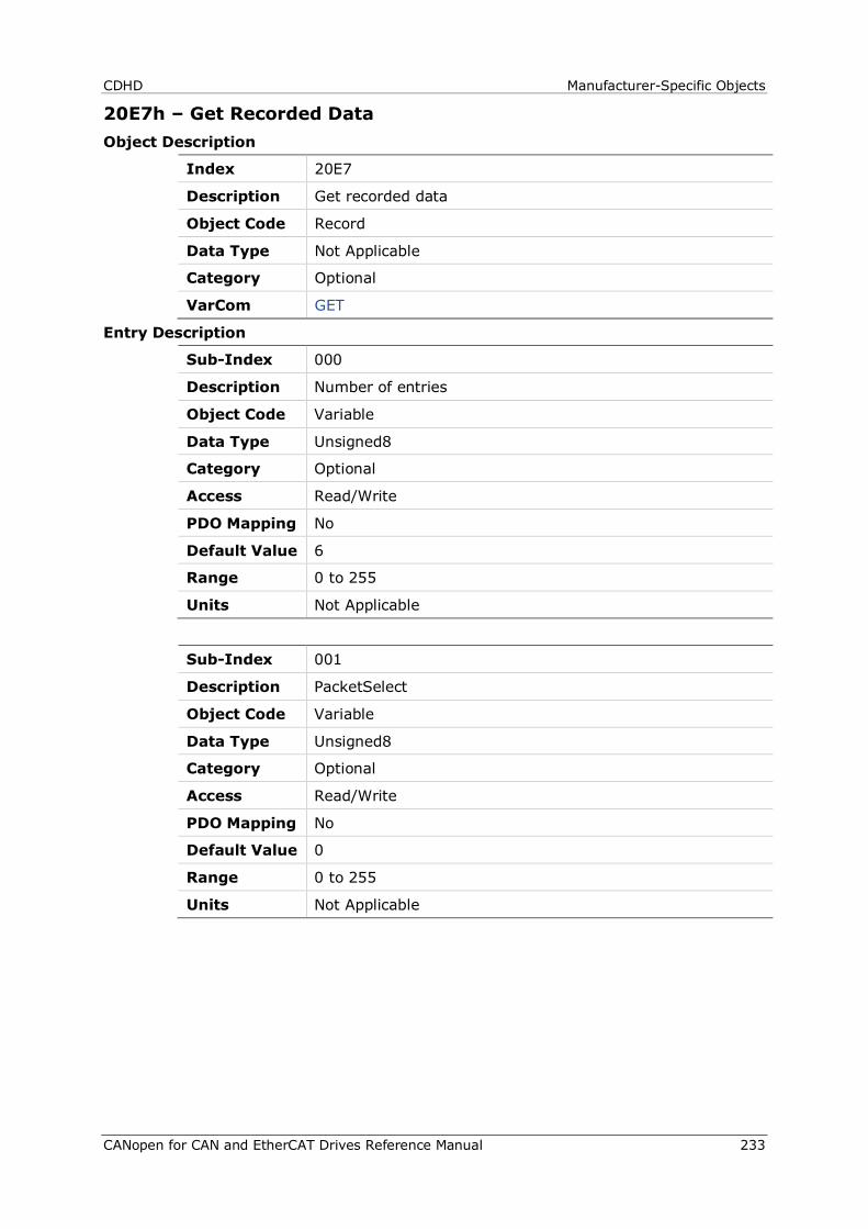
CDHD Manufacturer-Specific Objects
CANopen for CAN and EtherCAT Drives Reference Manual 233
20E7h – Get Recorded Data Object Description
Index 20E7
Description Get recorded data
Object Code Record
Data Type Not Applicable
Category Optional
VarCom GET
Entry Description
Sub-Index 000
Description Number of entries
Object Code Variable
Data Type Unsigned8
Category Optional
Access Read/Write
PDO Mapping No
Default Value 6
Range 0 to 255
Units Not Applicable
Sub-Index 001
Description PacketSelect
Object Code Variable
Data Type Unsigned8
Category Optional
Access Read/Write
PDO Mapping No
Default Value 0
Range 0 to 255
Units Not Applicable
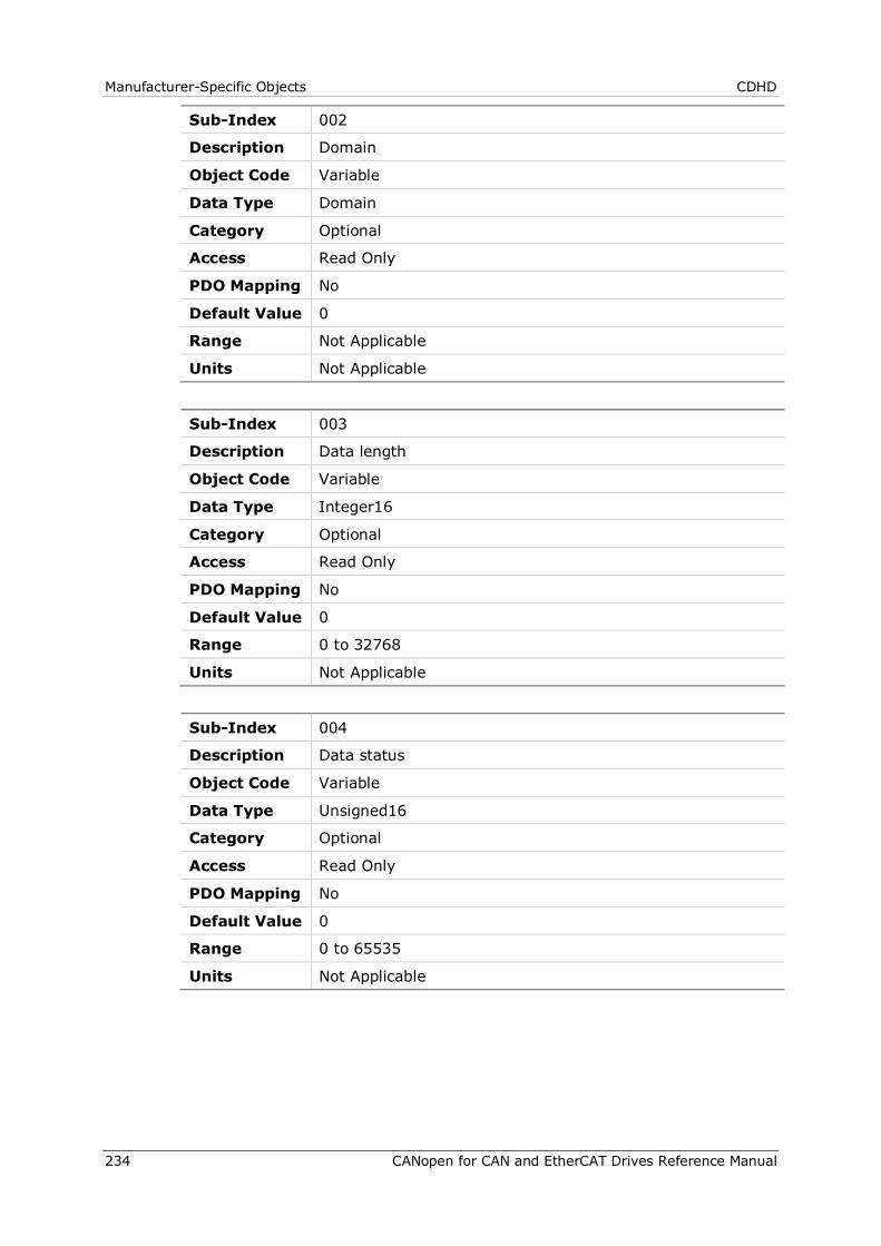
Manufacturer-Specific Objects CDHD
234 CANopen for CAN and EtherCAT Drives Reference Manual
Sub-Index 002
Description Domain
Object Code Variable
Data Type Domain
Category Optional
Access Read Only
PDO Mapping No
Default Value 0
Range Not Applicable
Units Not Applicable
Sub-Index 003
Description Data length
Object Code Variable
Data Type Integer16
Category Optional
Access Read Only
PDO Mapping No
Default Value 0
Range 0 to 32768
Units Not Applicable
Sub-Index 004
Description Data status
Object Code Variable
Data Type Unsigned16
Category Optional
Access Read Only
PDO Mapping No
Default Value 0
Range 0 to 65535
Units Not Applicable
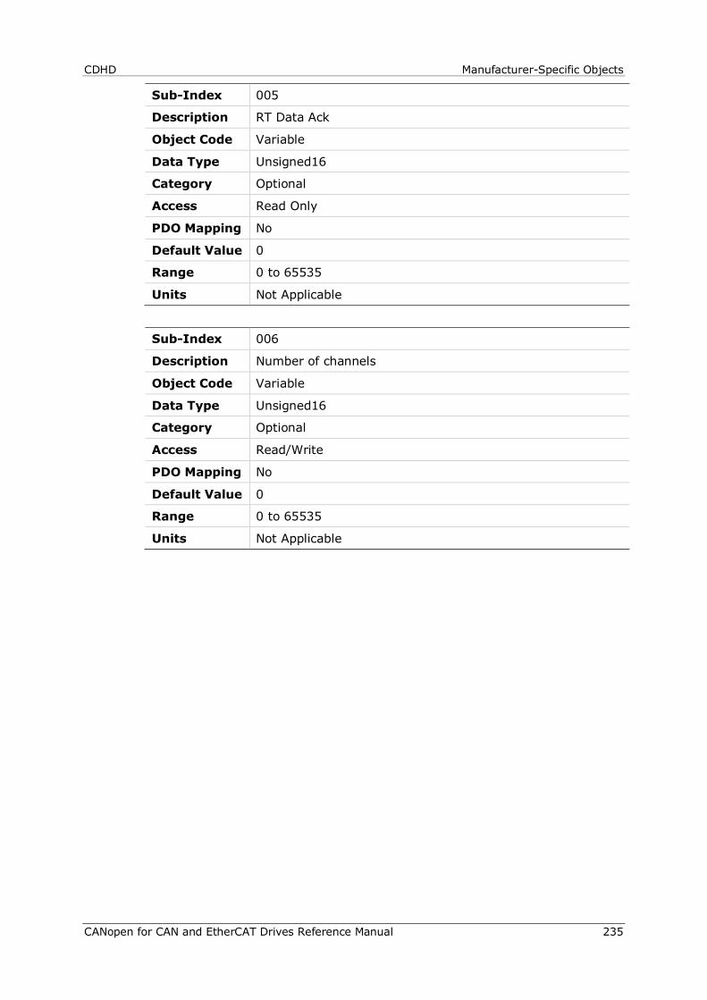
CDHD Manufacturer-Specific Objects
CANopen for CAN and EtherCAT Drives Reference Manual 235
Sub-Index 005
Description RT Data Ack
Object Code Variable
Data Type Unsigned16
Category Optional
Access Read Only
PDO Mapping No
Default Value 0
Range 0 to 65535
Units Not Applicable
Sub-Index 006
Description Number of channels
Object Code Variable
Data Type Unsigned16
Category Optional
Access Read/Write
PDO Mapping No
Default Value 0
Range 0 to 65535
Units Not Applicable
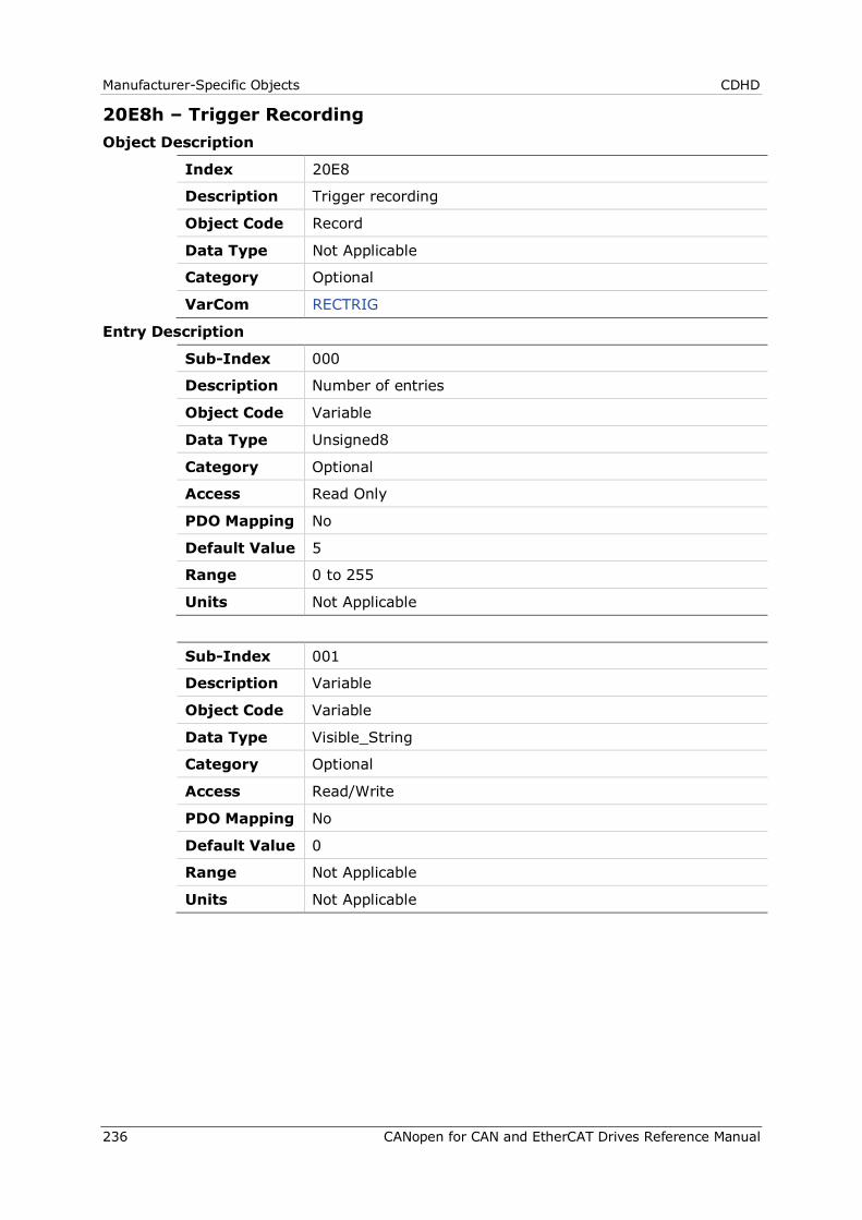
Manufacturer-Specific Objects CDHD
236 CANopen for CAN and EtherCAT Drives Reference Manual
20E8h – Trigger Recording Object Description
Index 20E8
Description Trigger recording
Object Code Record
Data Type Not Applicable
Category Optional
VarCom RECTRIG
Entry Description
Sub-Index 000
Description Number of entries
Object Code Variable
Data Type Unsigned8
Category Optional
Access Read Only
PDO Mapping No
Default Value 5
Range 0 to 255
Units Not Applicable
Sub-Index 001
Description Variable
Object Code Variable
Data Type Visible_String
Category Optional
Access Read/Write
PDO Mapping No
Default Value 0
Range Not Applicable
Units Not Applicable

CDHD Manufacturer-Specific Objects
CANopen for CAN and EtherCAT Drives Reference Manual 237
Sub-Index 002
Description Domain
Object Code Variable
Data Type Domain
Category Optional
Access Read/Write
PDO Mapping No
Default Value 0
Range Not Applicable
Units Not Applicable
Sub-Index 003
Description Pre-trig
Object Code Variable
Data Type Unsigned16
Category Optional
Access Read/Write
PDO Mapping No
Default Value 0
Range 0 to 65535
Units Not Applicable
Sub-Index 004
Description EdgePlr
Object Code Variable
Data Type Optional
Category Unsigned8
Access Read/Write
PDO Mapping No
Default Value 0
Range 0 to 255
Units Not Applicable
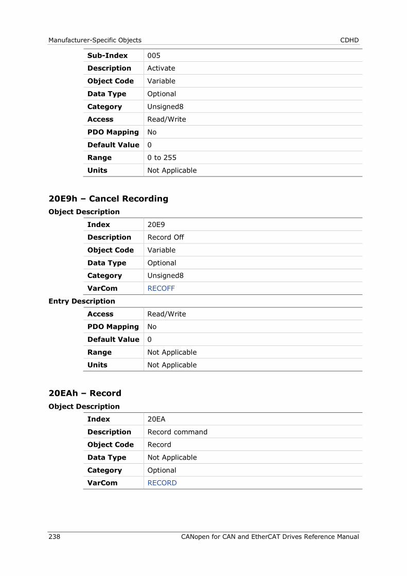
Manufacturer-Specific Objects CDHD
238 CANopen for CAN and EtherCAT Drives Reference Manual
Sub-Index 005
Description Activate
Object Code Variable
Data Type Optional
Category Unsigned8
Access Read/Write
PDO Mapping No
Default Value 0
Range 0 to 255
Units Not Applicable
20E9h – Cancel Recording Object Description
Index 20E9
Description Record Off
Object Code Variable
Data Type Optional
Category Unsigned8
VarCom RECOFF
Entry Description
Access Read/Write
PDO Mapping No
Default Value 0
Range Not Applicable
Units Not Applicable
20EAh – Record Object Description
Index 20EA
Description Record command
Object Code Record
Data Type Not Applicable
Category Optional
VarCom RECORD
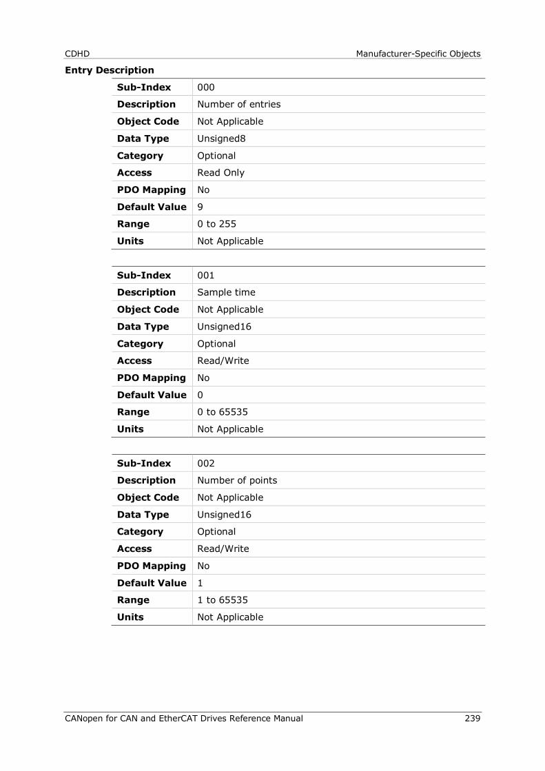
CDHD Manufacturer-Specific Objects
CANopen for CAN and EtherCAT Drives Reference Manual 239
Entry Description
Sub-Index 000
Description Number of entries
Object Code Not Applicable
Data Type Unsigned8
Category Optional
Access Read Only
PDO Mapping No
Default Value 9
Range 0 to 255
Units Not Applicable
Sub-Index 001
Description Sample time
Object Code Not Applicable
Data Type Unsigned16
Category Optional
Access Read/Write
PDO Mapping No
Default Value 0
Range 0 to 65535
Units Not Applicable
Sub-Index 002
Description Number of points
Object Code Not Applicable
Data Type Unsigned16
Category Optional
Access Read/Write
PDO Mapping No
Default Value 1
Range 1 to 65535
Units Not Applicable
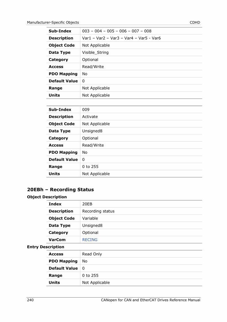
Manufacturer-Specific Objects CDHD
240 CANopen for CAN and EtherCAT Drives Reference Manual
Sub-Index 003 – 004 – 005 – 006 – 007 – 008
Description Var1 – Var2 – Var3 – Var4 – Var5 - Var6
Object Code Not Applicable
Data Type Visible_String
Category Optional
Access Read/Write
PDO Mapping No
Default Value 0
Range Not Applicable
Units Not Applicable
Sub-Index 009
Description Activate
Object Code Not Applicable
Data Type Unsigned8
Category Optional
Access Read/Write
PDO Mapping No
Default Value 0
Range 0 to 255
Units Not Applicable
20EBh – Recording Status Object Description
Index 20EB
Description Recording status
Object Code Variable
Data Type Unsigned8
Category Optional
VarCom RECING
Entry Description
Access Read Only
PDO Mapping No
Default Value 0
Range 0 to 255
Units Not Applicable
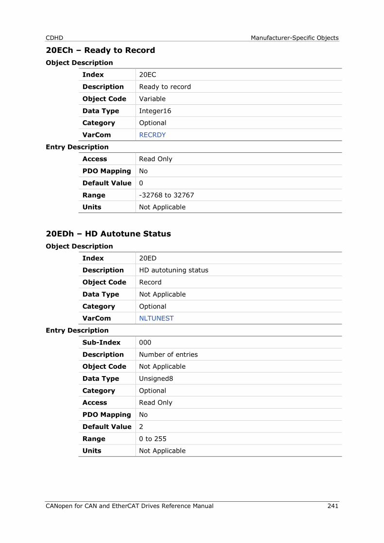
CDHD Manufacturer-Specific Objects
CANopen for CAN and EtherCAT Drives Reference Manual 241
20ECh – Ready to Record Object Description
Index 20EC
Description Ready to record
Object Code Variable
Data Type Integer16
Category Optional
VarCom RECRDY
Entry Description
Access Read Only
PDO Mapping No
Default Value 0
Range -32768 to 32767
Units Not Applicable
20EDh – HD Autotune Status Object Description
Index 20ED
Description HD autotuning status
Object Code Record
Data Type Not Applicable
Category Optional
VarCom NLTUNEST
Entry Description
Sub-Index 000
Description Number of entries
Object Code Not Applicable
Data Type Unsigned8
Category Optional
Access Read Only
PDO Mapping No
Default Value 2
Range 0 to 255
Units Not Applicable
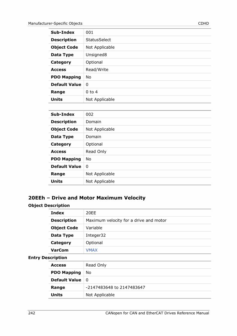
Manufacturer-Specific Objects CDHD
242 CANopen for CAN and EtherCAT Drives Reference Manual
Sub-Index 001
Description StatusSelect
Object Code Not Applicable
Data Type Unsigned8
Category Optional
Access Read/Write
PDO Mapping No
Default Value 0
Range 0 to 4
Units Not Applicable
Sub-Index 002
Description Domain
Object Code Not Applicable
Data Type Domain
Category Optional
Access Read Only
PDO Mapping No
Default Value 0
Range Not Applicable
Units Not Applicable
20EEh – Drive and Motor Maximum Velocity Object Description
Index 20EE
Description Maximum velocity for a drive and motor
Object Code Variable
Data Type Integer32
Category Optional
VarCom VMAX
Entry Description
Access Read Only
PDO Mapping No
Default Value 0
Range -2147483648 to 2147483647
Units Not Applicable

CDHD Manufacturer-Specific Objects
CANopen for CAN and EtherCAT Drives Reference Manual 243
20EFh – Dead Time Compensation Minimal Level Object Description
Index 20EF
Description Minimal current level to start compensate dead time effect.
Object Code Variable
Data Type Real32
Category Optional
VarCom KCD
Entry Description
Access Read/Write
PDO Mapping No
Default Value 1.0
Range 0 to 10
Units Not Applicable
20F0h – Drive and Motor Maximum Current Object Description
Index 20F0
Description Maximum current for a drive and motor combination.
Object Code Variable
Data Type Integer32
Category Optional
VarCom IMAX
Entry Description
Access Read Only
PDO Mapping No
Default Value 0
Range 150000
Units milliampere (mA)
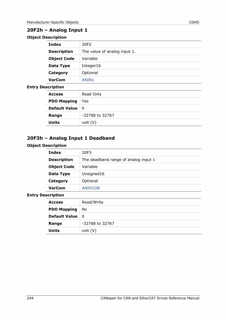
Manufacturer-Specific Objects CDHD
244 CANopen for CAN and EtherCAT Drives Reference Manual
20F2h – Analog Input 1 Object Description
Index 20F2
Description The value of analog input 1.
Object Code Variable
Data Type Integer16
Category Optional
VarCom ANIN1
Entry Description
Access Read Only
PDO Mapping Yes
Default Value 0
Range -32768 to 32767
Units volt (V)
20F3h – Analog Input 1 Deadband Object Description
Index 20F3
Description The deadband range of analog input 1
Object Code Variable
Data Type Unsigned16
Category Optional
VarCom ANIN1DB
Entry Description
Access Read/Write
PDO Mapping No
Default Value 0
Range -32768 to 32767
Units volt (V)
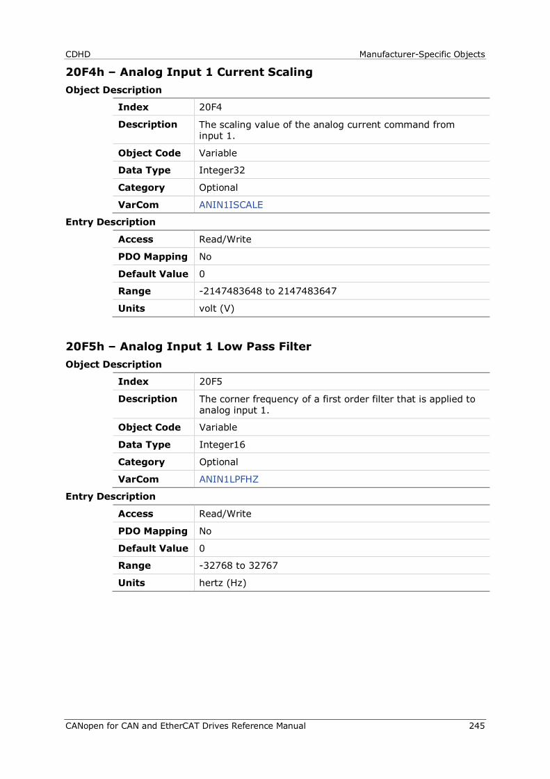
CDHD Manufacturer-Specific Objects
CANopen for CAN and EtherCAT Drives Reference Manual 245
20F4h – Analog Input 1 Current Scaling Object Description
Index 20F4
Description The scaling value of the analog current command from input 1.
Object Code Variable
Data Type Integer32
Category Optional
VarCom ANIN1ISCALE
Entry Description
Access Read/Write
PDO Mapping No
Default Value 0
Range -2147483648 to 2147483647
Units volt (V)
20F5h – Analog Input 1 Low Pass Filter Object Description
Index 20F5
Description The corner frequency of a first order filter that is applied to analog input 1.
Object Code Variable
Data Type Integer16
Category Optional
VarCom ANIN1LPFHZ
Entry Description
Access Read/Write
PDO Mapping No
Default Value 0
Range -32768 to 32767
Units hertz (Hz)
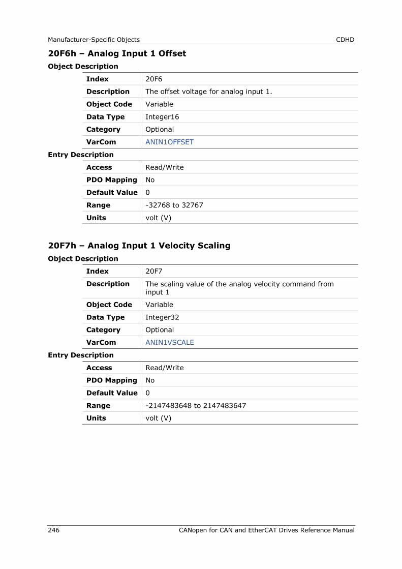
Manufacturer-Specific Objects CDHD
246 CANopen for CAN and EtherCAT Drives Reference Manual
20F6h – Analog Input 1 Offset Object Description
Index 20F6
Description The offset voltage for analog input 1.
Object Code Variable
Data Type Integer16
Category Optional
VarCom ANIN1OFFSET
Entry Description
Access Read/Write
PDO Mapping No
Default Value 0
Range -32768 to 32767
Units volt (V)
20F7h – Analog Input 1 Velocity Scaling Object Description
Index 20F7
Description The scaling value of the analog velocity command from input 1
Object Code Variable
Data Type Integer32
Category Optional
VarCom ANIN1VSCALE
Entry Description
Access Read/Write
PDO Mapping No
Default Value 0
Range -2147483648 to 2147483647
Units volt (V)
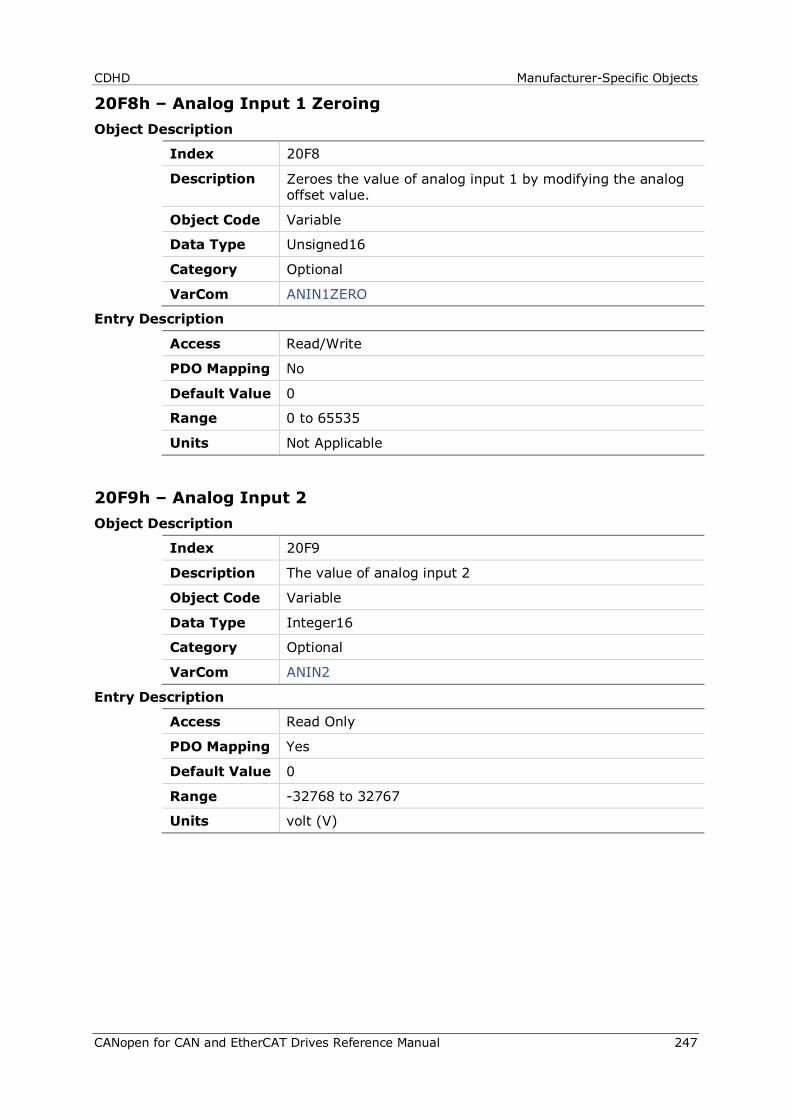
CDHD Manufacturer-Specific Objects
CANopen for CAN and EtherCAT Drives Reference Manual 247
20F8h – Analog Input 1 Zeroing Object Description
Index 20F8
Description Zeroes the value of analog input 1 by modifying the analog offset value.
Object Code Variable
Data Type Unsigned16
Category Optional
VarCom ANIN1ZERO
Entry Description
Access Read/Write
PDO Mapping No
Default Value 0
Range 0 to 65535
Units Not Applicable
20F9h – Analog Input 2 Object Description
Index 20F9
Description The value of analog input 2
Object Code Variable
Data Type Integer16
Category Optional
VarCom ANIN2
Entry Description
Access Read Only
PDO Mapping Yes
Default Value 0
Range -32768 to 32767
Units volt (V)
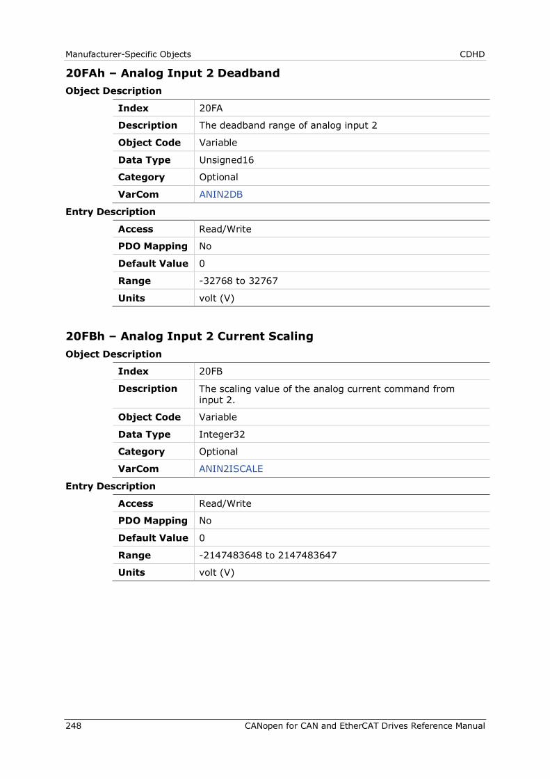
Manufacturer-Specific Objects CDHD
248 CANopen for CAN and EtherCAT Drives Reference Manual
20FAh – Analog Input 2 Deadband Object Description
Index 20FA
Description The deadband range of analog input 2
Object Code Variable
Data Type Unsigned16
Category Optional
VarCom ANIN2DB
Entry Description
Access Read/Write
PDO Mapping No
Default Value 0
Range -32768 to 32767
Units volt (V)
20FBh – Analog Input 2 Current Scaling Object Description
Index 20FB
Description The scaling value of the analog current command from input 2.
Object Code Variable
Data Type Integer32
Category Optional
VarCom ANIN2ISCALE
Entry Description
Access Read/Write
PDO Mapping No
Default Value 0
Range -2147483648 to 2147483647
Units volt (V)
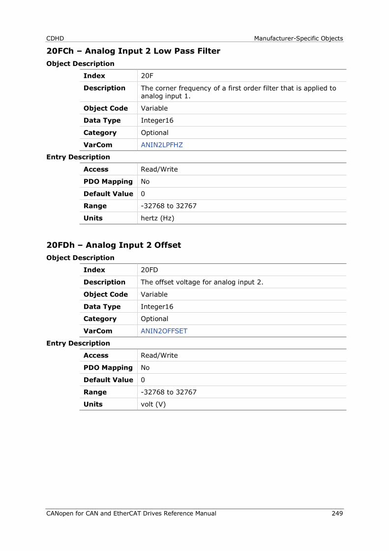
CDHD Manufacturer-Specific Objects
CANopen for CAN and EtherCAT Drives Reference Manual 249
20FCh – Analog Input 2 Low Pass Filter Object Description
Index 20F
Description The corner frequency of a first order filter that is applied to analog input 1.
Object Code Variable
Data Type Integer16
Category Optional
VarCom ANIN2LPFHZ
Entry Description
Access Read/Write
PDO Mapping No
Default Value 0
Range -32768 to 32767
Units hertz (Hz)
20FDh – Analog Input 2 Offset Object Description
Index 20FD
Description The offset voltage for analog input 2.
Object Code Variable
Data Type Integer16
Category Optional
VarCom ANIN2OFFSET
Entry Description
Access Read/Write
PDO Mapping No
Default Value 0
Range -32768 to 32767
Units volt (V)
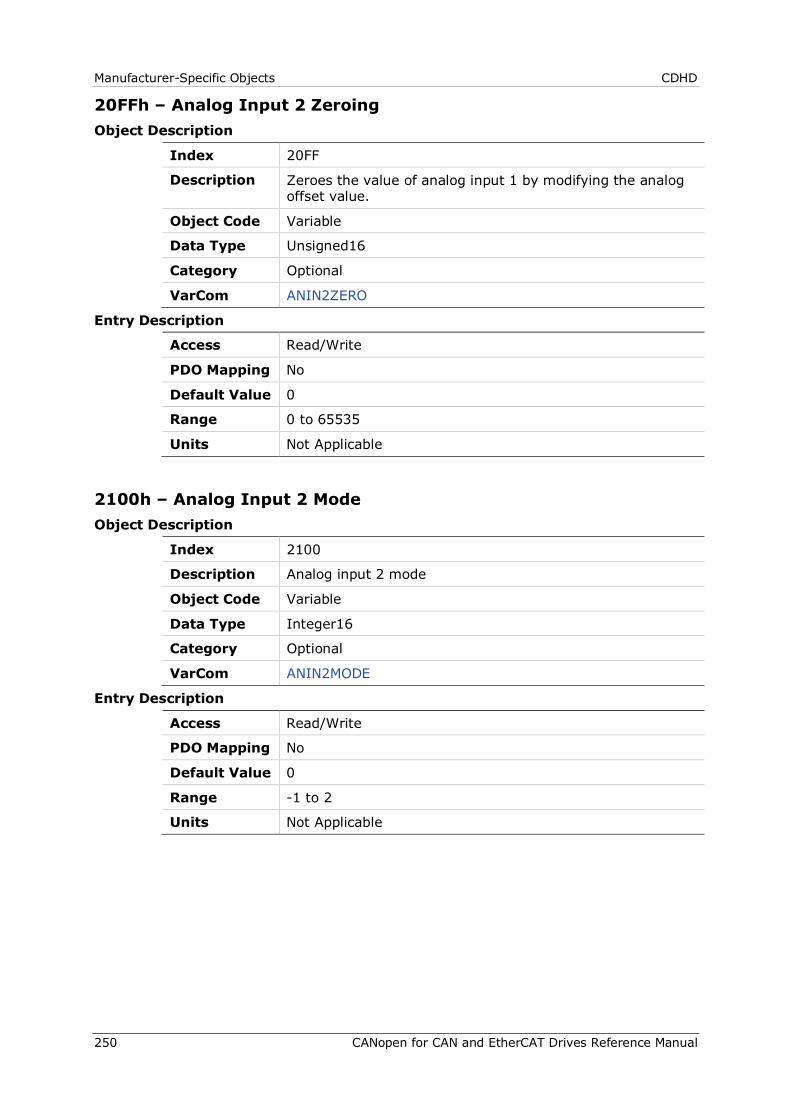
Manufacturer-Specific Objects CDHD
250 CANopen for CAN and EtherCAT Drives Reference Manual
20FFh – Analog Input 2 Zeroing Object Description
Index 20FF
Description Zeroes the value of analog input 1 by modifying the analog offset value.
Object Code Variable
Data Type Unsigned16
Category Optional
VarCom ANIN2ZERO
Entry Description
Access Read/Write
PDO Mapping No
Default Value 0
Range 0 to 65535
Units Not Applicable
2100h – Analog Input 2 Mode Object Description
Index 2100
Description Analog input 2 mode
Object Code Variable
Data Type Integer16
Category Optional
VarCom ANIN2MODE
Entry Description
Access Read/Write
PDO Mapping No
Default Value 0
Range -1 to 2
Units Not Applicable
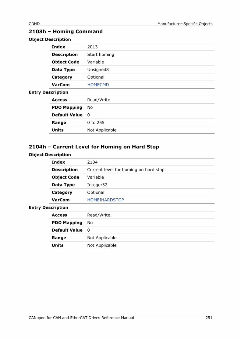
CDHD Manufacturer-Specific Objects
CANopen for CAN and EtherCAT Drives Reference Manual 251
2103h – Homing Command Object Description
Index 2013
Description Start homing
Object Code Variable
Data Type Unsigned8
Category Optional
VarCom HOMECMD
Entry Description
Access Read/Write
PDO Mapping No
Default Value 0
Range 0 to 255
Units Not Applicable
2104h – Current Level for Homing on Hard Stop Object Description
Index 2104
Description Current level for homing on hard stop
Object Code Variable
Data Type Integer32
Category Optional
VarCom HOMEIHARDSTOP
Entry Description
Access Read/Write
PDO Mapping No
Default Value 0
Range Not Applicable
Units Not Applicable

Manufacturer-Specific Objects CDHD
252 CANopen for CAN and EtherCAT Drives Reference Manual
2106h – Current Loop Compatibility Mode Object Description
Index 2106
Description Current loop compatibility mode
Object Code Variable
Data Type Integer16
Category Optional
VarCom KCMODE
Entry Description
Access Read/Write
PDO Mapping No
Default Value 0
Range Not Applicable
Units Not Applicable
2108h – Point-to-Point Move Average Object Description
Index 2108
Description Point-to-point move averaging number
Object Code Variable
Data Type Real32
Category Optional
VarCom MOVESMOOTHAVG
Entry Description
Access Read/Write
PDO Mapping No
Default Value 0
Range Not Applicable
Units Not Applicable
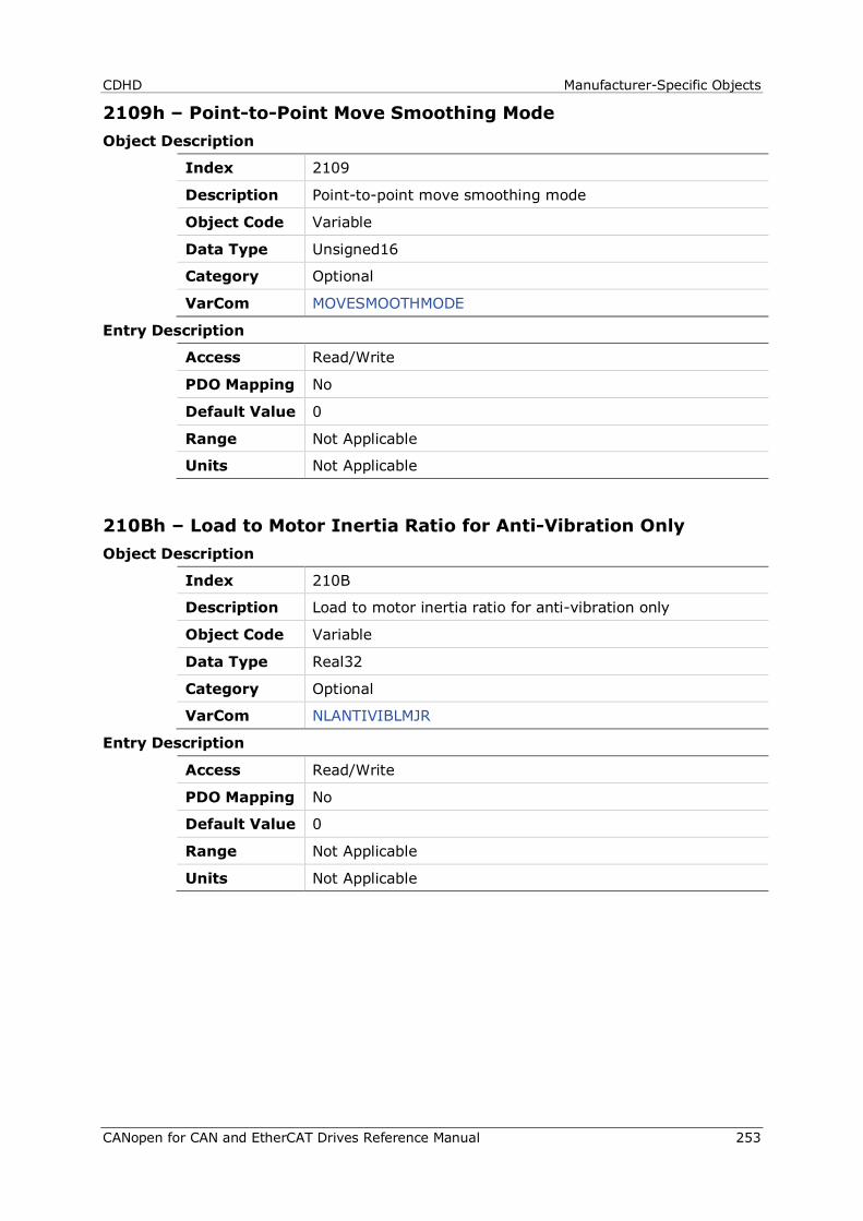
CDHD Manufacturer-Specific Objects
CANopen for CAN and EtherCAT Drives Reference Manual 253
2109h – Point-to-Point Move Smoothing Mode Object Description
Index 2109
Description Point-to-point move smoothing mode
Object Code Variable
Data Type Unsigned16
Category Optional
VarCom MOVESMOOTHMODE
Entry Description
Access Read/Write
PDO Mapping No
Default Value 0
Range Not Applicable
Units Not Applicable
210Bh – Load to Motor Inertia Ratio for Anti-Vibration Only Object Description
Index 210B
Description Load to motor inertia ratio for anti-vibration only
Object Code Variable
Data Type Real32
Category Optional
VarCom NLANTIVIBLMJR
Entry Description
Access Read/Write
PDO Mapping No
Default Value 0
Range Not Applicable
Units Not Applicable
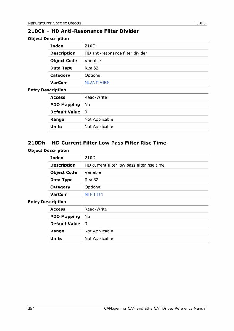
Manufacturer-Specific Objects CDHD
254 CANopen for CAN and EtherCAT Drives Reference Manual
210Ch – HD Anti-Resonance Filter Divider Object Description
Index 210C
Description HD anti-resonance filter divider
Object Code Variable
Data Type Real32
Category Optional
VarCom NLANTIVIBN
Entry Description
Access Read/Write
PDO Mapping No
Default Value 0
Range Not Applicable
Units Not Applicable
210Dh – HD Current Filter Low Pass Filter Rise Time Object Description
Index 210D
Description HD current filter low pass filter rise time
Object Code Variable
Data Type Real32
Category Optional
VarCom NLFILTT1
Entry Description
Access Read/Write
PDO Mapping No
Default Value 0
Range Not Applicable
Units Not Applicable
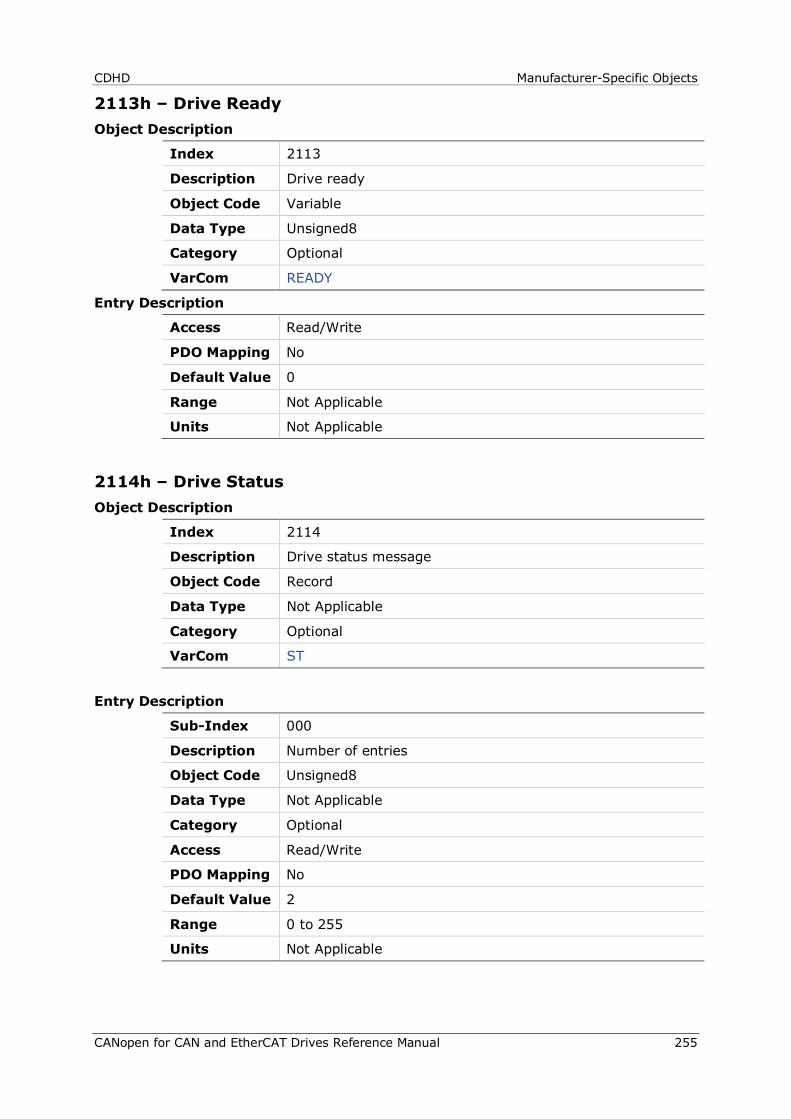
CDHD Manufacturer-Specific Objects
CANopen for CAN and EtherCAT Drives Reference Manual 255
2113h – Drive Ready Object Description
Index 2113
Description Drive ready
Object Code Variable
Data Type Unsigned8
Category Optional
VarCom READY
Entry Description
Access Read/Write
PDO Mapping No
Default Value 0
Range Not Applicable
Units Not Applicable
2114h – Drive Status Object Description
Index 2114
Description Drive status message
Object Code Record
Data Type Not Applicable
Category Optional
VarCom ST
Entry Description
Sub-Index 000
Description Number of entries
Object Code Unsigned8
Data Type Not Applicable
Category Optional
Access Read/Write
PDO Mapping No
Default Value 2
Range 0 to 255
Units Not Applicable
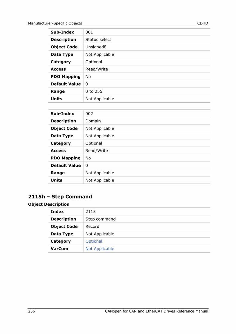
Manufacturer-Specific Objects CDHD
256 CANopen for CAN and EtherCAT Drives Reference Manual
Sub-Index 001
Description Status select
Object Code Unsigned8
Data Type Not Applicable
Category Optional
Access Read/Write
PDO Mapping No
Default Value 0
Range 0 to 255
Units Not Applicable
Sub-Index 002
Description Domain
Object Code Not Applicable
Data Type Not Applicable
Category Optional
Access Read/Write
PDO Mapping No
Default Value 0
Range Not Applicable
Units Not Applicable
2115h – Step Command Object Description
Index 2115
Description Step command
Object Code Record
Data Type Not Applicable
Category Optional
VarCom Not Applicable
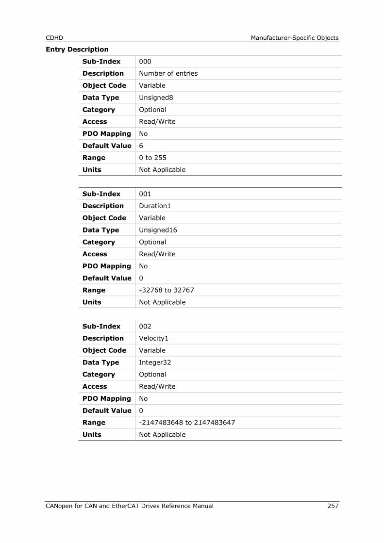
CDHD Manufacturer-Specific Objects
CANopen for CAN and EtherCAT Drives Reference Manual 257
Entry Description
Sub-Index 000
Description Number of entries
Object Code Variable
Data Type Unsigned8
Category Optional
Access Read/Write
PDO Mapping No
Default Value 6
Range 0 to 255
Units Not Applicable
Sub-Index 001
Description Duration1
Object Code Variable
Data Type Unsigned16
Category Optional
Access Read/Write
PDO Mapping No
Default Value 0
Range -32768 to 32767
Units Not Applicable
Sub-Index 002
Description Velocity1
Object Code Variable
Data Type Integer32
Category Optional
Access Read/Write
PDO Mapping No
Default Value 0
Range -2147483648 to 2147483647
Units Not Applicable
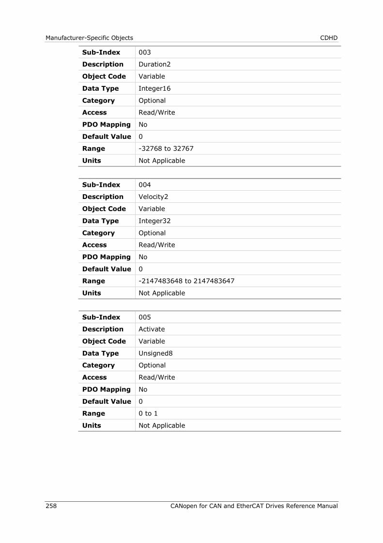
Manufacturer-Specific Objects CDHD
258 CANopen for CAN and EtherCAT Drives Reference Manual
Sub-Index 003
Description Duration2
Object Code Variable
Data Type Integer16
Category Optional
Access Read/Write
PDO Mapping No
Default Value 0
Range -32768 to 32767
Units Not Applicable
Sub-Index 004
Description Velocity2
Object Code Variable
Data Type Integer32
Category Optional
Access Read/Write
PDO Mapping No
Default Value 0
Range -2147483648 to 2147483647
Units Not Applicable
Sub-Index 005
Description Activate
Object Code Variable
Data Type Unsigned8
Category Optional
Access Read/Write
PDO Mapping No
Default Value 0
Range 0 to 1
Units Not Applicable
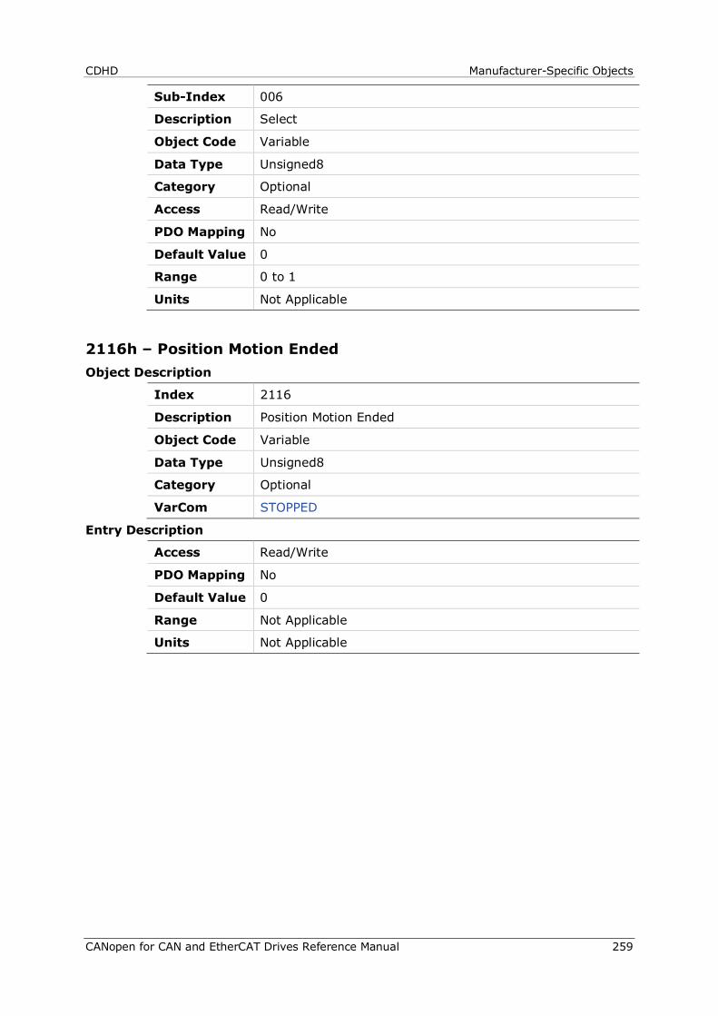
CDHD Manufacturer-Specific Objects
CANopen for CAN and EtherCAT Drives Reference Manual 259
Sub-Index 006
Description Select
Object Code Variable
Data Type Unsigned8
Category Optional
Access Read/Write
PDO Mapping No
Default Value 0
Range 0 to 1
Units Not Applicable
2116h – Position Motion Ended Object Description
Index 2116
Description Position Motion Ended
Object Code Variable
Data Type Unsigned8
Category Optional
VarCom STOPPED
Entry Description
Access Read/Write
PDO Mapping No
Default Value 0
Range Not Applicable
Units Not Applicable
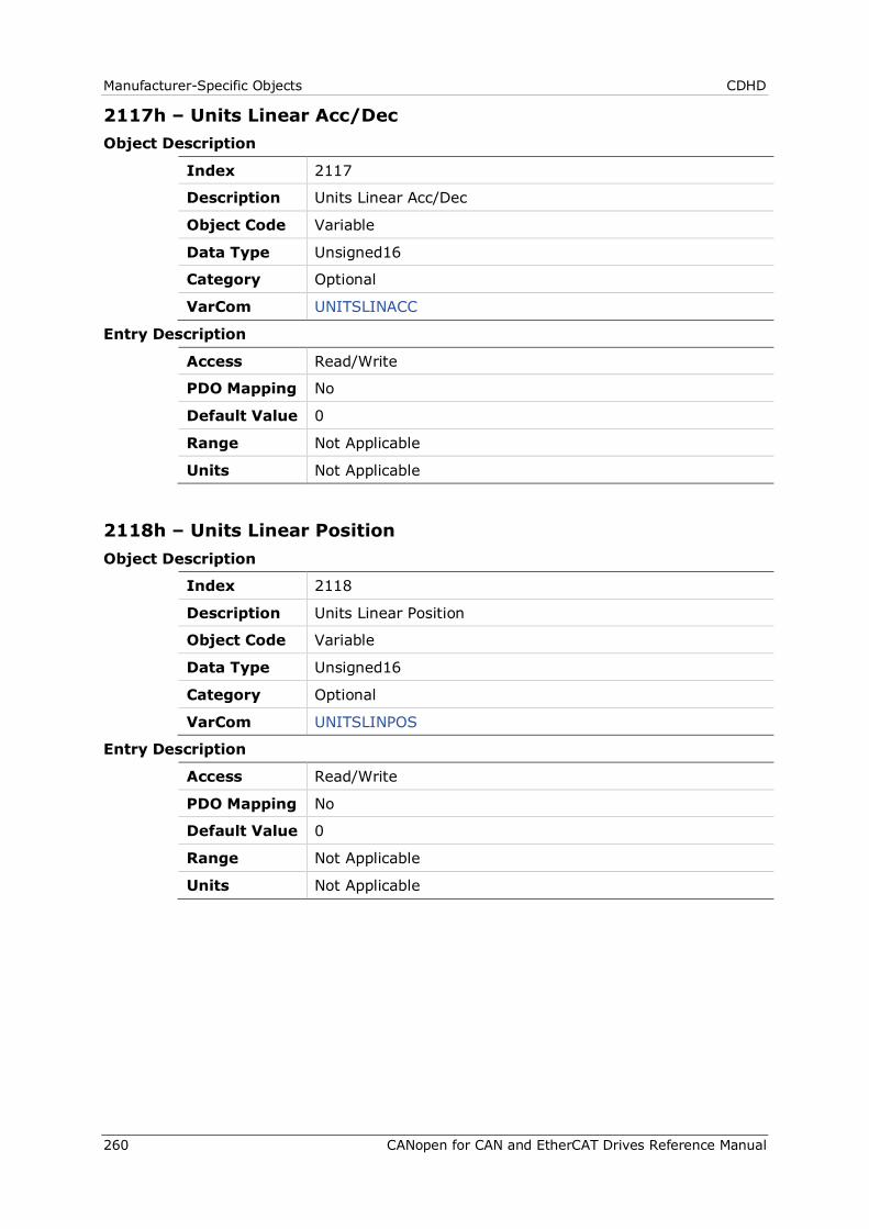
Manufacturer-Specific Objects CDHD
260 CANopen for CAN and EtherCAT Drives Reference Manual
2117h – Units Linear Acc/Dec Object Description
Index 2117
Description Units Linear Acc/Dec
Object Code Variable
Data Type Unsigned16
Category Optional
VarCom UNITSLINACC
Entry Description
Access Read/Write
PDO Mapping No
Default Value 0
Range Not Applicable
Units Not Applicable
2118h – Units Linear Position Object Description
Index 2118
Description Units Linear Position
Object Code Variable
Data Type Unsigned16
Category Optional
VarCom UNITSLINPOS
Entry Description
Access Read/Write
PDO Mapping No
Default Value 0
Range Not Applicable
Units Not Applicable
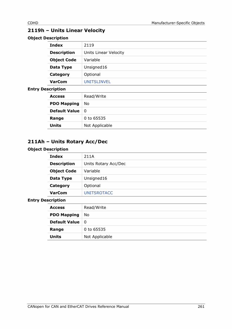
CDHD Manufacturer-Specific Objects
CANopen for CAN and EtherCAT Drives Reference Manual 261
2119h – Units Linear Velocity Object Description
Index 2119
Description Units Linear Velocity
Object Code Variable
Data Type Unsigned16
Category Optional
VarCom UNITSLINVEL
Entry Description
Access Read/Write
PDO Mapping No
Default Value 0
Range 0 to 65535
Units Not Applicable
211Ah – Units Rotary Acc/Dec Object Description
Index 211A
Description Units Rotary Acc/Dec
Object Code Variable
Data Type Unsigned16
Category Optional
VarCom UNITSROTACC
Entry Description
Access Read/Write
PDO Mapping No
Default Value 0
Range 0 to 65535
Units Not Applicable
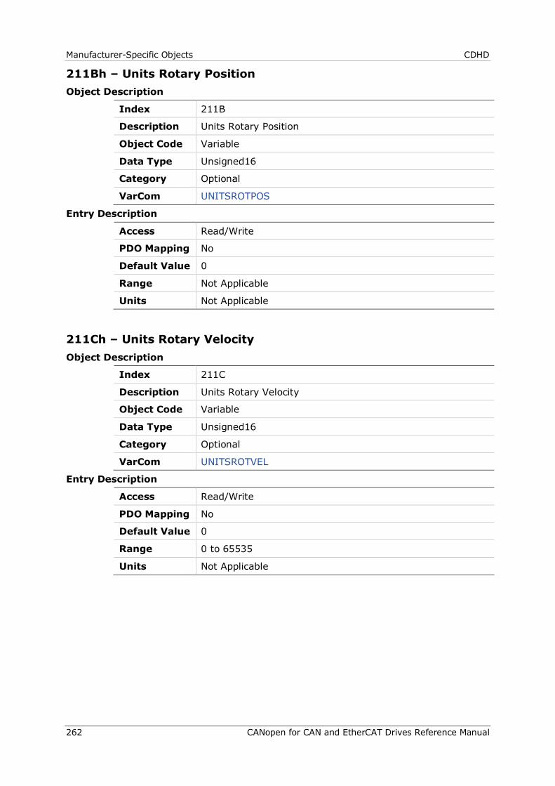
Manufacturer-Specific Objects CDHD
262 CANopen for CAN and EtherCAT Drives Reference Manual
211Bh – Units Rotary Position Object Description
Index 211B
Description Units Rotary Position
Object Code Variable
Data Type Unsigned16
Category Optional
VarCom UNITSROTPOS
Entry Description
Access Read/Write
PDO Mapping No
Default Value 0
Range Not Applicable
Units Not Applicable
211Ch – Units Rotary Velocity Object Description
Index 211C
Description Units Rotary Velocity
Object Code Variable
Data Type Unsigned16
Category Optional
VarCom UNITSROTVEL
Entry Description
Access Read/Write
PDO Mapping No
Default Value 0
Range 0 to 65535
Units Not Applicable
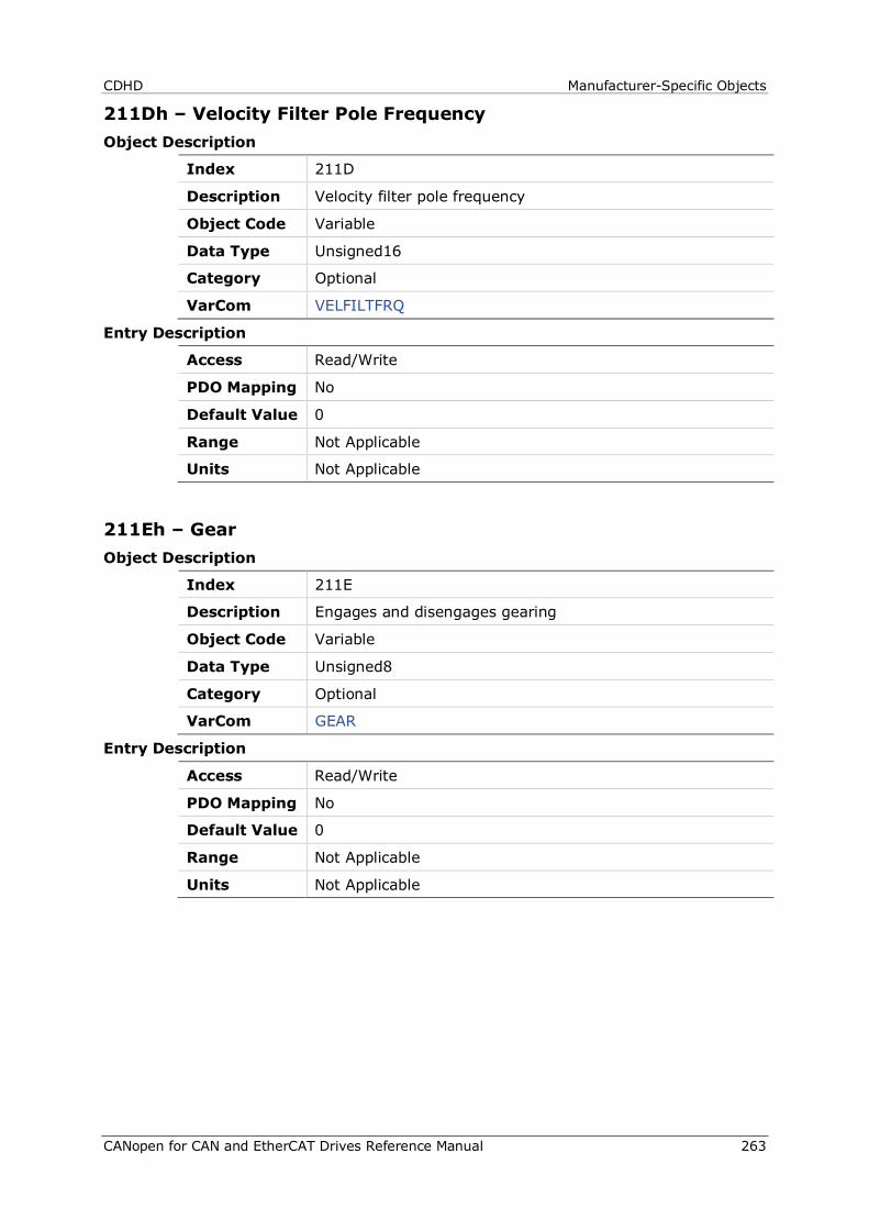
CDHD Manufacturer-Specific Objects
CANopen for CAN and EtherCAT Drives Reference Manual 263
211Dh – Velocity Filter Pole Frequency Object Description
Index 211D
Description Velocity filter pole frequency
Object Code Variable
Data Type Unsigned16
Category Optional
VarCom VELFILTFRQ
Entry Description
Access Read/Write
PDO Mapping No
Default Value 0
Range Not Applicable
Units Not Applicable
211Eh – Gear Object Description
Index 211E
Description Engages and disengages gearing
Object Code Variable
Data Type Unsigned8
Category Optional
VarCom GEAR
Entry Description
Access Read/Write
PDO Mapping No
Default Value 0
Range Not Applicable
Units Not Applicable
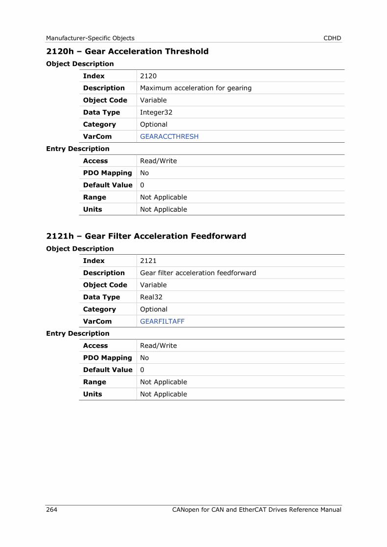
Manufacturer-Specific Objects CDHD
264 CANopen for CAN and EtherCAT Drives Reference Manual
2120h – Gear Acceleration Threshold Object Description
Index 2120
Description Maximum acceleration for gearing
Object Code Variable
Data Type Integer32
Category Optional
VarCom GEARACCTHRESH
Entry Description
Access Read/Write
PDO Mapping No
Default Value 0
Range Not Applicable
Units Not Applicable
2121h – Gear Filter Acceleration Feedforward Object Description
Index 2121
Description Gear filter acceleration feedforward
Object Code Variable
Data Type Real32
Category Optional
VarCom GEARFILTAFF
Entry Description
Access Read/Write
PDO Mapping No
Default Value 0
Range Not Applicable
Units Not Applicable
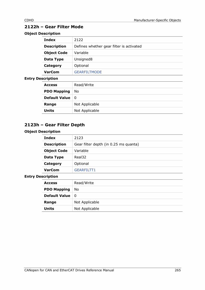
CDHD Manufacturer-Specific Objects
CANopen for CAN and EtherCAT Drives Reference Manual 265
2122h – Gear Filter Mode Object Description
Index 2122
Description Defines whether gear filter is activated
Object Code Variable
Data Type Unsigned8
Category Optional
VarCom GEARFILTMODE
Entry Description
Access Read/Write
PDO Mapping No
Default Value 0
Range Not Applicable
Units Not Applicable
2123h – Gear Filter Depth Object Description
Index 2123
Description Gear filter depth (in 0.25 ms quanta)
Object Code Variable
Data Type Real32
Category Optional
VarCom GEARFILTT1
Entry Description
Access Read/Write
PDO Mapping No
Default Value 0
Range Not Applicable
Units Not Applicable
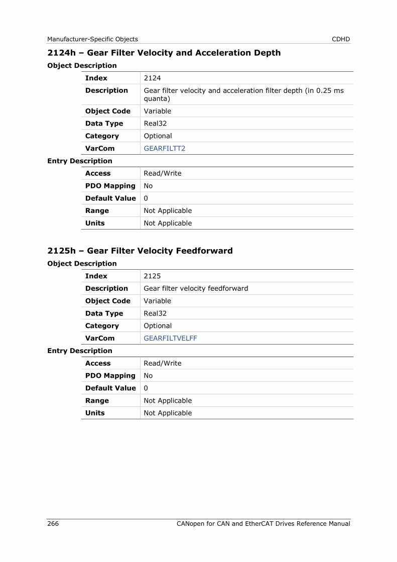
Manufacturer-Specific Objects CDHD
266 CANopen for CAN and EtherCAT Drives Reference Manual
2124h – Gear Filter Velocity and Acceleration Depth Object Description
Index 2124
Description Gear filter velocity and acceleration filter depth (in 0.25 ms quanta)
Object Code Variable
Data Type Real32
Category Optional
VarCom GEARFILTT2
Entry Description
Access Read/Write
PDO Mapping No
Default Value 0
Range Not Applicable
Units Not Applicable
2125h – Gear Filter Velocity Feedforward Object Description
Index 2125
Description Gear filter velocity feedforward
Object Code Variable
Data Type Real32
Category Optional
VarCom GEARFILTVELFF
Entry Description
Access Read/Write
PDO Mapping No
Default Value 0
Range Not Applicable
Units Not Applicable
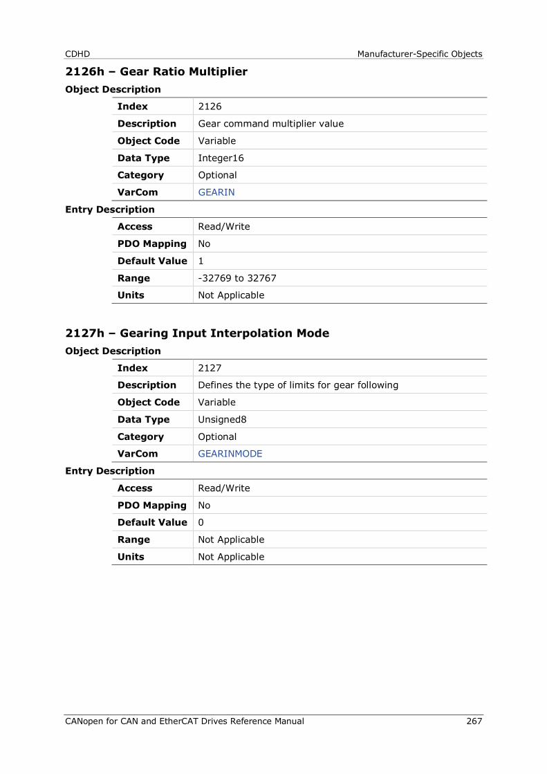
CDHD Manufacturer-Specific Objects
CANopen for CAN and EtherCAT Drives Reference Manual 267
2126h – Gear Ratio Multiplier Object Description
Index 2126
Description Gear command multiplier value
Object Code Variable
Data Type Integer16
Category Optional
VarCom GEARIN
Entry Description
Access Read/Write
PDO Mapping No
Default Value 1
Range -32769 to 32767
Units Not Applicable
2127h – Gearing Input Interpolation Mode Object Description
Index 2127
Description Defines the type of limits for gear following
Object Code Variable
Data Type Unsigned8
Category Optional
VarCom GEARINMODE
Entry Description
Access Read/Write
PDO Mapping No
Default Value 0
Range Not Applicable
Units Not Applicable
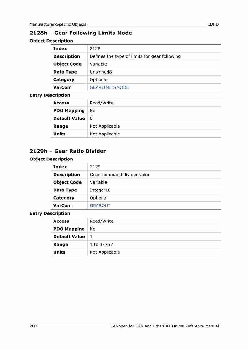
Manufacturer-Specific Objects CDHD
268 CANopen for CAN and EtherCAT Drives Reference Manual
2128h – Gear Following Limits Mode Object Description
Index 2128
Description Defines the type of limits for gear following
Object Code Variable
Data Type Unsigned8
Category Optional
VarCom GEARLIMITSMODE
Entry Description
Access Read/Write
PDO Mapping No
Default Value 0
Range Not Applicable
Units Not Applicable
2129h – Gear Ratio Divider Object Description
Index 2129
Description Gear command divider value
Object Code Variable
Data Type Integer16
Category Optional
VarCom GEAROUT
Entry Description
Access Read/Write
PDO Mapping No
Default Value 1
Range 1 to 32767
Units Not Applicable
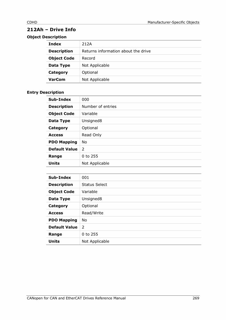
CDHD Manufacturer-Specific Objects
CANopen for CAN and EtherCAT Drives Reference Manual 269
212Ah – Drive Info Object Description
Index 212A
Description Returns information about the drive
Object Code Record
Data Type Not Applicable
Category Optional
VarCom Not Applicable
Entry Description
Sub-Index 000
Description Number of entries
Object Code Variable
Data Type Unsigned8
Category Optional
Access Read Only
PDO Mapping No
Default Value 2
Range 0 to 255
Units Not Applicable
Sub-Index 001
Description Status Select
Object Code Variable
Data Type Unsigned8
Category Optional
Access Read/Write
PDO Mapping No
Default Value 2
Range 0 to 255
Units Not Applicable
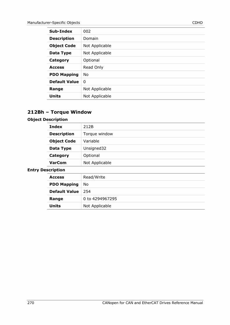
Manufacturer-Specific Objects CDHD
270 CANopen for CAN and EtherCAT Drives Reference Manual
Sub-Index 002
Description Domain
Object Code Not Applicable
Data Type Not Applicable
Category Optional
Access Read Only
PDO Mapping No
Default Value 0
Range Not Applicable
Units Not Applicable
212Bh – Torque Window Object Description
Index 212B
Description Torque window
Object Code Variable
Data Type Unsigned32
Category Optional
VarCom Not Applicable
Entry Description
Access Read/Write
PDO Mapping No
Default Value 254
Range 0 to 4294967295
Units Not Applicable
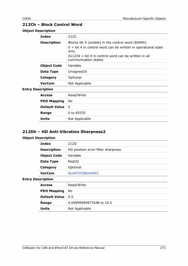
CDHD Manufacturer-Specific Objects
CANopen for CAN and EtherCAT Drives Reference Manual 271
212Ch – Block Control Word Object Description
Index 212C
Description Blocks bit 4 (enable) in the control word (6040h). 0 = bit 4 in control word can be written in operational state only. 0x1234 = bit 4 in control word can be written in all communication states.
Object Code Variable
Data Type Unsigned16
Category Optional
VarCom Not Applicable
Entry Description
Access Read/Write
PDO Mapping No
Default Value 0
Range 0 to 65535
Units Not Applicable
212Dh – HD Anti-Vibration Sharpness2 Object Description
Index 212D
Description HD position error filter sharpness
Object Code Variable
Data Type Real32
Category Optional
VarCom NLANTIVIBSHARP2
Entry Description
Access Read/Write
PDO Mapping No
Default Value 0.5
Range 0.00999999977648 to 10.0
Units Not Applicable
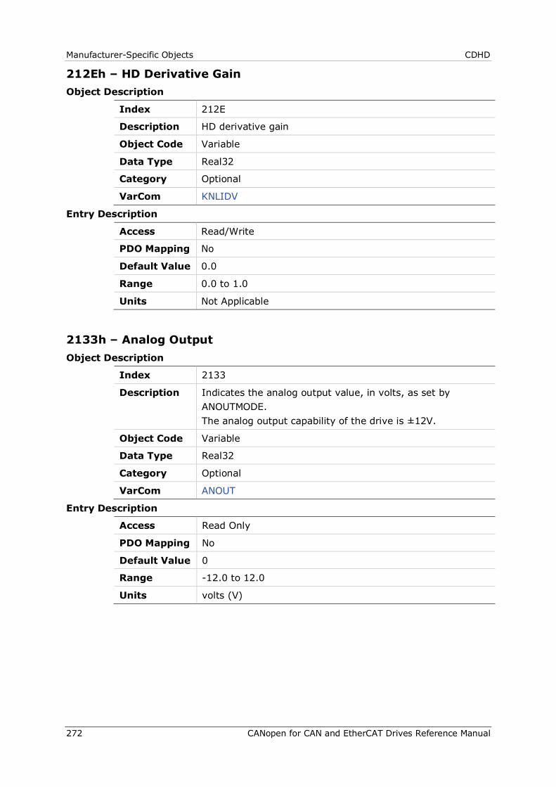
Manufacturer-Specific Objects CDHD
272 CANopen for CAN and EtherCAT Drives Reference Manual
212Eh – HD Derivative Gain Object Description
Index 212E
Description HD derivative gain
Object Code Variable
Data Type Real32
Category Optional
VarCom KNLIDV
Entry Description
Access Read/Write
PDO Mapping No
Default Value 0.0
Range 0.0 to 1.0
Units Not Applicable
2133h – Analog Output Object Description
Index 2133
Description Indicates the analog output value, in volts, as set by ANOUTMODE. The analog output capability of the drive is ±12V.
Object Code Variable
Data Type Real32
Category Optional
VarCom ANOUT
Entry Description
Access Read Only
PDO Mapping No
Default Value 0
Range -12.0 to 12.0
Units volts (V)
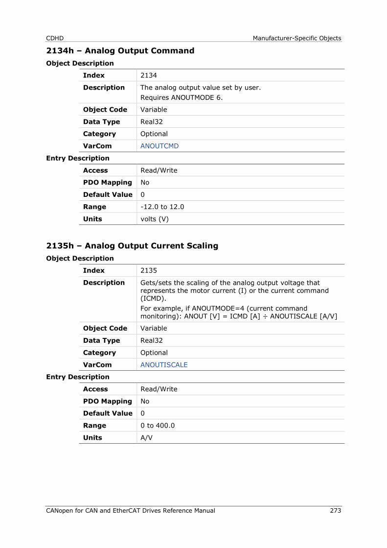
CDHD Manufacturer-Specific Objects
CANopen for CAN and EtherCAT Drives Reference Manual 273
2134h – Analog Output Command Object Description
Index 2134
Description The analog output value set by user. Requires ANOUTMODE 6.
Object Code Variable
Data Type Real32
Category Optional
VarCom ANOUTCMD
Entry Description
Access Read/Write
PDO Mapping No
Default Value 0
Range -12.0 to 12.0
Units volts (V)
2135h – Analog Output Current Scaling Object Description
Index 2135
Description Gets/sets the scaling of the analog output voltage that represents the motor current (I) or the current command (ICMD). For example, if ANOUTMODE=4 (current command monitoring): ANOUT [V] = ICMD [A] ÷ ANOUTISCALE [A/V]
Object Code Variable
Data Type Real32
Category Optional
VarCom ANOUTISCALE
Entry Description
Access Read/Write
PDO Mapping No
Default Value 0
Range 0 to 400.0
Units A/V
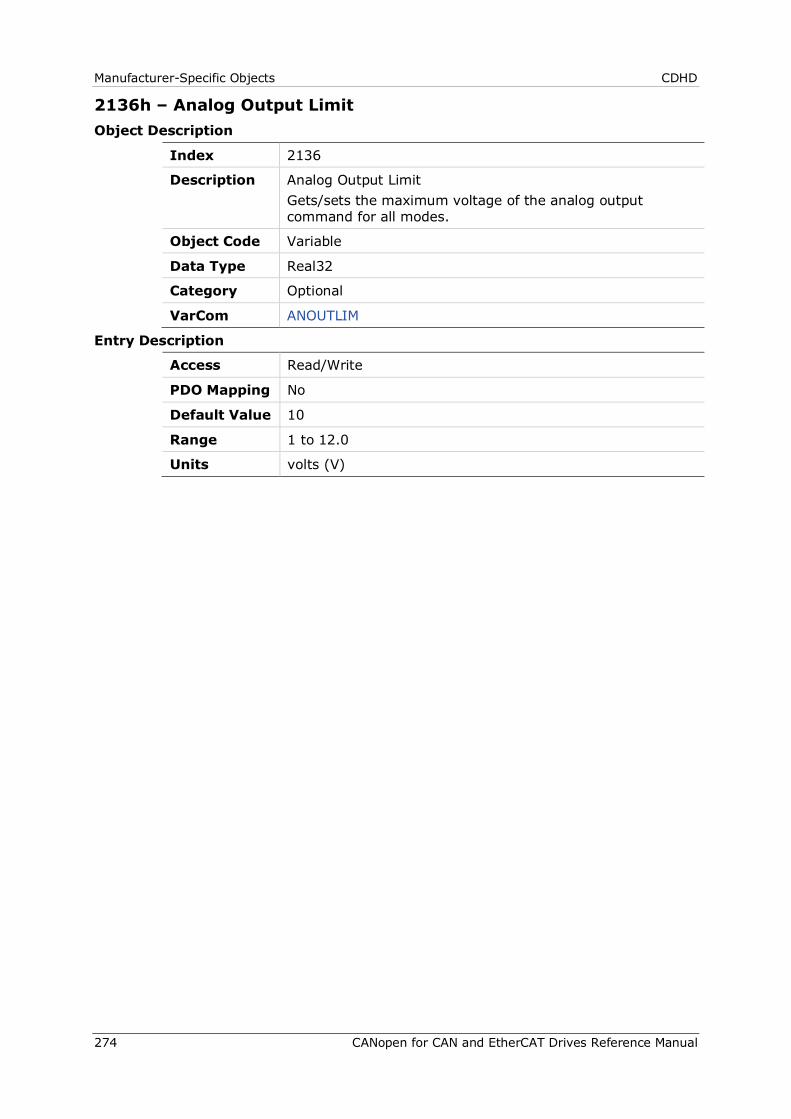
Manufacturer-Specific Objects CDHD
274 CANopen for CAN and EtherCAT Drives Reference Manual
2136h – Analog Output Limit Object Description
Index 2136
Description Analog Output Limit Gets/sets the maximum voltage of the analog output command for all modes.
Object Code Variable
Data Type Real32
Category Optional
VarCom ANOUTLIM
Entry Description
Access Read/Write
PDO Mapping No
Default Value 10
Range 1 to 12.0
Units volts (V)
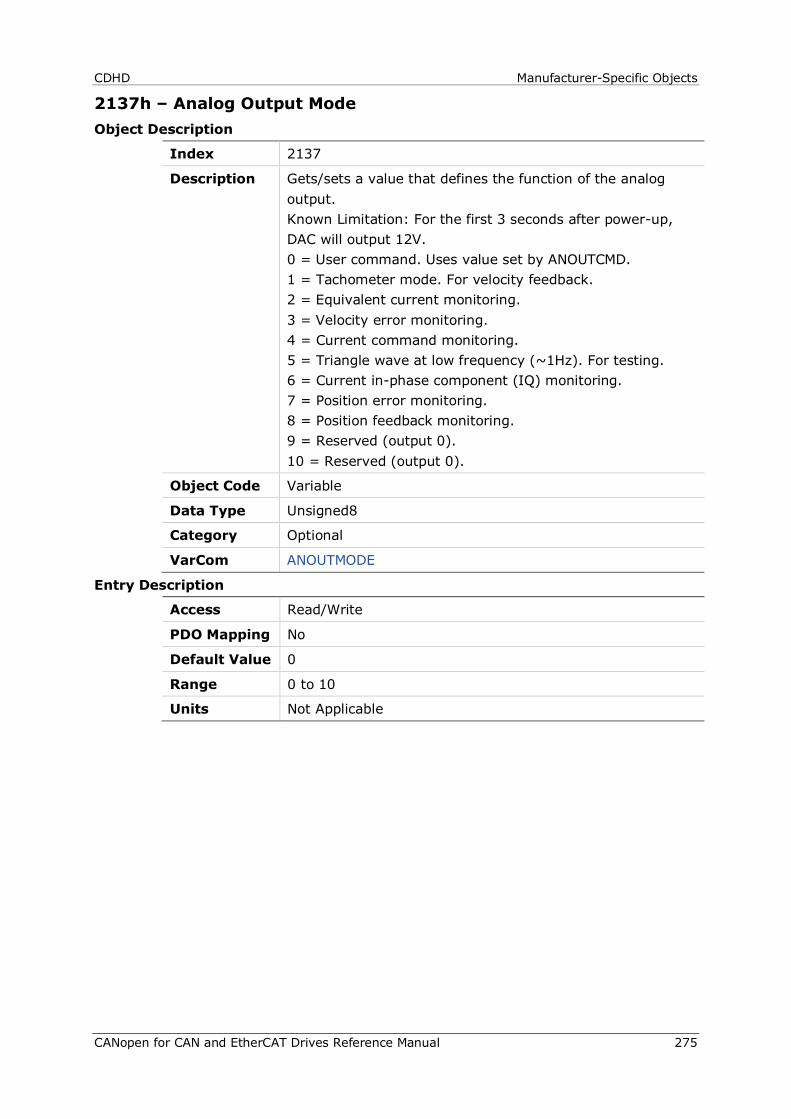
CDHD Manufacturer-Specific Objects
CANopen for CAN and EtherCAT Drives Reference Manual 275
2137h – Analog Output Mode Object Description
Index 2137
Description Gets/sets a value that defines the function of the analog output. Known Limitation: For the first 3 seconds after power-up, DAC will output 12V. 0 = User command. Uses value set by ANOUTCMD. 1 = Tachometer mode. For velocity feedback. 2 = Equivalent current monitoring. 3 = Velocity error monitoring. 4 = Current command monitoring. 5 = Triangle wave at low frequency (~1Hz). For testing. 6 = Current in-phase component (IQ) monitoring. 7 = Position error monitoring. 8 = Position feedback monitoring. 9 = Reserved (output 0). 10 = Reserved (output 0).
Object Code Variable
Data Type Unsigned8
Category Optional
VarCom ANOUTMODE
Entry Description
Access Read/Write
PDO Mapping No
Default Value 0
Range 0 to 10
Units Not Applicable

Manufacturer-Specific Objects CDHD
276 CANopen for CAN and EtherCAT Drives Reference Manual
2138h – Analog Output Velocity Scaling Object Description
Index 2138
Description Gets/sets the scaling of the analog output voltage that represents the actual velocity (V) or the velocity error (VE).
Object Code Variable
Data Type Real32
Category Optional
VarCom ANOUTVSCALE
Entry Description
Access Read/Write
PDO Mapping No
Default Value 0.0
Range 0.0 to 12.0
Units Not Applicable
2142h – Primary Position Actual Value Object Description
Index 2142
Description The actual position, according to the primary feedback device.
Object Code Variable
Data Type Integer32
Category Optional
VarCom Not Applicable
Entry Description
Access Read Only
PDO Mapping Yes
Default Value 0
Range -2147483648 to 2147483647
Units Not Applicable
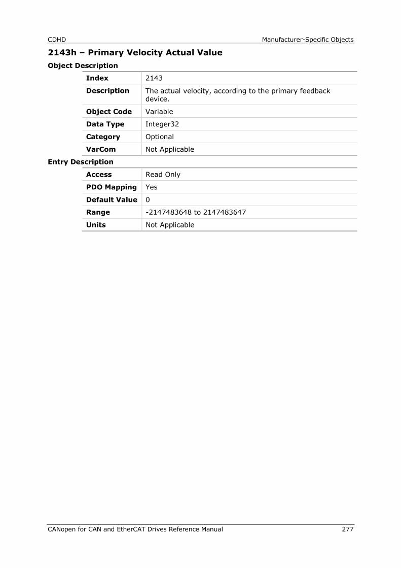
CDHD Manufacturer-Specific Objects
CANopen for CAN and EtherCAT Drives Reference Manual 277
2143h – Primary Velocity Actual Value Object Description
Index 2143
Description The actual velocity, according to the primary feedback device.
Object Code Variable
Data Type Integer32
Category Optional
VarCom Not Applicable
Entry Description
Access Read Only
PDO Mapping Yes
Default Value 0
Range -2147483648 to 2147483647
Units Not Applicable
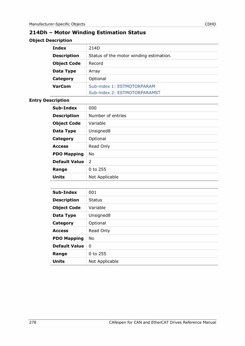
Manufacturer-Specific Objects CDHD
278 CANopen for CAN and EtherCAT Drives Reference Manual
214Dh – Motor Winding Estimation Status Object Description
Index 214D
Description Status of the motor winding estimation.
Object Code Record
Data Type Array
Category Optional
VarCom Sub-index 1: ESTMOTORPARAM Sub-index 2: ESTMOTORPARAMST
Entry Description
Sub-Index 000
Description Number of entries
Object Code Variable
Data Type Unsigned8
Category Optional
Access Read Only
PDO Mapping No
Default Value 2
Range 0 to 255
Units Not Applicable
Sub-Index 001
Description Status
Object Code Variable
Data Type Unsigned8
Category Optional
Access Read Only
PDO Mapping No
Default Value 0
Range 0 to 255
Units Not Applicable
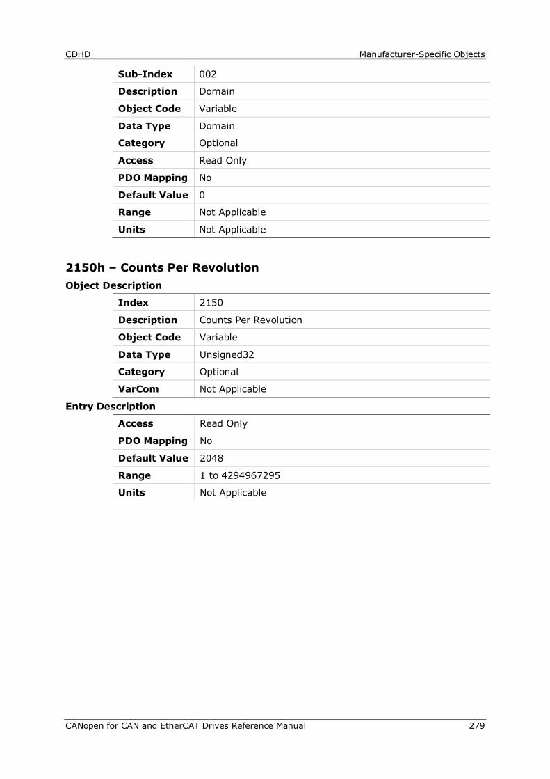
CDHD Manufacturer-Specific Objects
CANopen for CAN and EtherCAT Drives Reference Manual 279
Sub-Index 002
Description Domain
Object Code Variable
Data Type Domain
Category Optional
Access Read Only
PDO Mapping No
Default Value 0
Range Not Applicable
Units Not Applicable
2150h – Counts Per Revolution Object Description
Index 2150
Description Counts Per Revolution
Object Code Variable
Data Type Unsigned32
Category Optional
VarCom Not Applicable
Entry Description
Access Read Only
PDO Mapping No
Default Value 2048
Range 1 to 4294967295
Units Not Applicable

Standard Servo Drive Objects CDHD
280 CANopen for CAN and EtherCAT Drives Reference Manual
6 Standard Servo Drive Objects
The following standard device profile objects are implemented in the CDHD.
For more information, refer to the relevant CAN documentation.
603Fh – Error Code Object Description
Index 603F
Description Indicates the error code of the last error that occurred in the drive device.
Object Code Variable
Data Type Unsigned16
Category Optional
VarCom FLT
Entry Description
Access Read Only
PDO Mapping No
Default Value 0
Range 0 to 65535
Units Not Applicable

CDHD Standard Servo Drive Objects
CANopen for CAN and EtherCAT Drives Reference Manual 281
6040h – Controlword Object Description
Index 6040
Description Sets the operating states and modes of the state machine. This object is organized bit-wise. The bits have the following meaning: Bit Description 0 = switch on 1 = enable voltage 2 = quick stop 3 = enable operation 4-6 = mode-specific 7 = fault reset 8 = halt 9 = mode-specific 10 = reserved 11-15 = manufacturer-specific
Object Code Variable
Data Type Unsigned16
Category Optional
VarCom Not Applicable

Standard Servo Drive Objects CDHD
282 CANopen for CAN and EtherCAT Drives Reference Manual
Entry Description
Access Read/Write
PDO Mapping Yes
Default Value 0
Range 0 to 65535
Units Not Applicable
6041h – Statusword Object Description
Index 6041
Description Indicates the current state of the FSA, the operation mode and manufacturer-specific entities. This object is organized bit-wise. The bits have the following meaning: Bit Description 0 = ready to switch on 1 = switched on 2 = operation enabled 3 = fault 4 = voltage enabled 5 = quick stop 6 = switch on disabled 7 = warning 8 = manufacturer-specific 9 = remote 10 = target reached 11 = internal limit active 12-13 = mode-specific 14-15 = manufacturer-specific
Object Code Variable
Data Type Unsigned16
Category Optional
VarCom Not Applicable
Entry Description
Access Read Only
PDO Mapping Yes
Default Value 0
Range 0 to 65535
Units Not Applicable
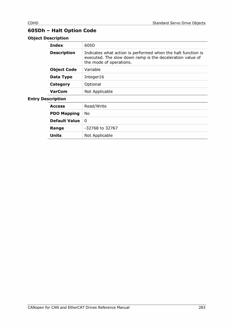
CDHD Standard Servo Drive Objects
CANopen for CAN and EtherCAT Drives Reference Manual 283
605Dh – Halt Option Code Object Description
Index 605D
Description Indicates what action is performed when the halt function is executed. The slow down ramp is the deceleration value of the mode of operations.
Object Code Variable
Data Type Integer16
Category Optional
VarCom Not Applicable
Entry Description
Access Read/Write
PDO Mapping No
Default Value 0
Range -32768 to 32767
Units Not Applicable
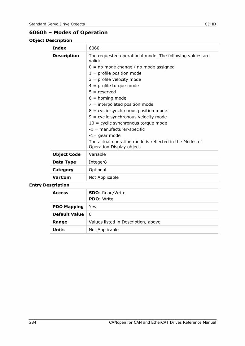
Standard Servo Drive Objects CDHD
284 CANopen for CAN and EtherCAT Drives Reference Manual
6060h – Modes of Operation Object Description
Index 6060
Description The requested operational mode. The following values are valid: 0 = no mode change / no mode assigned 1 = profile position mode 3 = profile velocity mode 4 = profile torque mode 5 = reserved 6 = homing mode 7 = interpolated position mode 8 = cyclic synchronous position mode 9 = cyclic synchronous velocity mode 10 = cyclic synchronous torque mode -x = manufacturer-specific -1= gear mode The actual operation mode is reflected in the Modes of Operation Display object.
Object Code Variable
Data Type Integer8
Category Optional
VarCom Not Applicable
Entry Description
Access SDO: Read/Write PDO: Write
PDO Mapping Yes
Default Value 0
Range Values listed in Description, above
Units Not Applicable
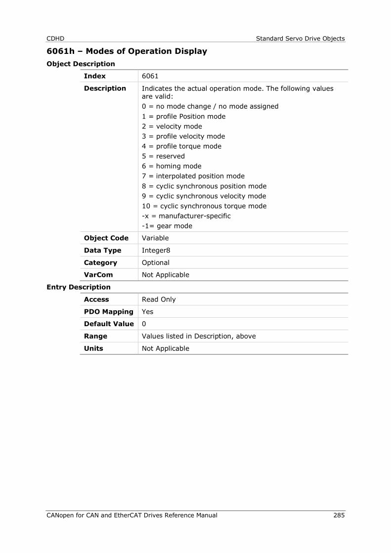
CDHD Standard Servo Drive Objects
CANopen for CAN and EtherCAT Drives Reference Manual 285
6061h – Modes of Operation Display Object Description
Index 6061
Description Indicates the actual operation mode. The following values are valid: 0 = no mode change / no mode assigned 1 = profile Position mode 2 = velocity mode 3 = profile velocity mode 4 = profile torque mode 5 = reserved 6 = homing mode 7 = interpolated position mode 8 = cyclic synchronous position mode 9 = cyclic synchronous velocity mode 10 = cyclic synchronous torque mode -x = manufacturer-specific -1= gear mode
Object Code Variable
Data Type Integer8
Category Optional
VarCom Not Applicable
Entry Description
Access Read Only
PDO Mapping Yes
Default Value 0
Range Values listed in Description, above
Units Not Applicable
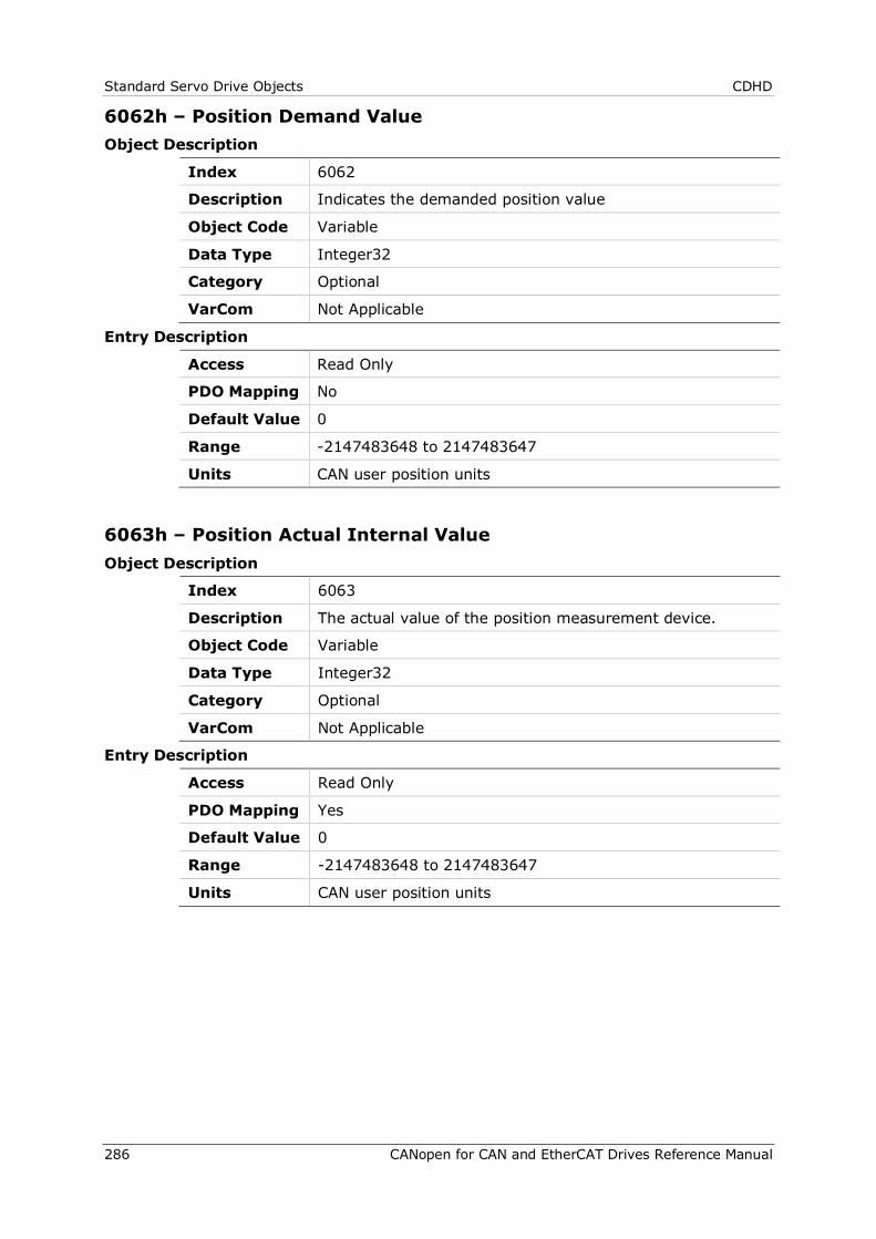
Standard Servo Drive Objects CDHD
286 CANopen for CAN and EtherCAT Drives Reference Manual
6062h – Position Demand Value Object Description
Index 6062
Description Indicates the demanded position value
Object Code Variable
Data Type Integer32
Category Optional
VarCom Not Applicable
Entry Description
Access Read Only
PDO Mapping No
Default Value 0
Range -2147483648 to 2147483647
Units CAN user position units
6063h – Position Actual Internal Value Object Description
Index 6063
Description The actual value of the position measurement device.
Object Code Variable
Data Type Integer32
Category Optional
VarCom Not Applicable
Entry Description
Access Read Only
PDO Mapping Yes
Default Value 0
Range -2147483648 to 2147483647
Units CAN user position units
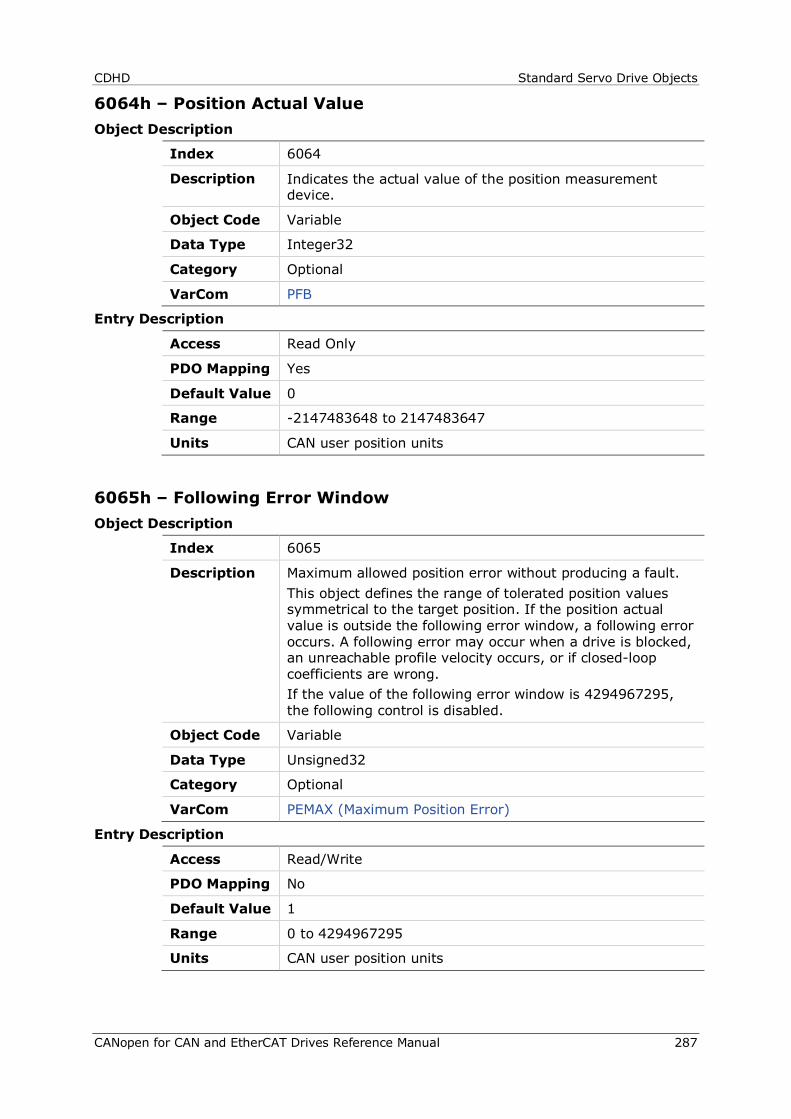
CDHD Standard Servo Drive Objects
CANopen for CAN and EtherCAT Drives Reference Manual 287
6064h – Position Actual Value Object Description
Index 6064
Description Indicates the actual value of the position measurement device.
Object Code Variable
Data Type Integer32
Category Optional
VarCom PFB
Entry Description
Access Read Only
PDO Mapping Yes
Default Value 0
Range -2147483648 to 2147483647
Units CAN user position units
6065h – Following Error Window Object Description
Index 6065
Description Maximum allowed position error without producing a fault. This object defines the range of tolerated position values symmetrical to the target position. If the position actual value is outside the following error window, a following error occurs. A following error may occur when a drive is blocked, an unreachable profile velocity occurs, or if closed-loop coefficients are wrong. If the value of the following error window is 4294967295, the following control is disabled.
Object Code Variable
Data Type Unsigned32
Category Optional
VarCom PEMAX (Maximum Position Error)
Entry Description
Access Read/Write
PDO Mapping No
Default Value 1
Range 0 to 4294967295
Units CAN user position units
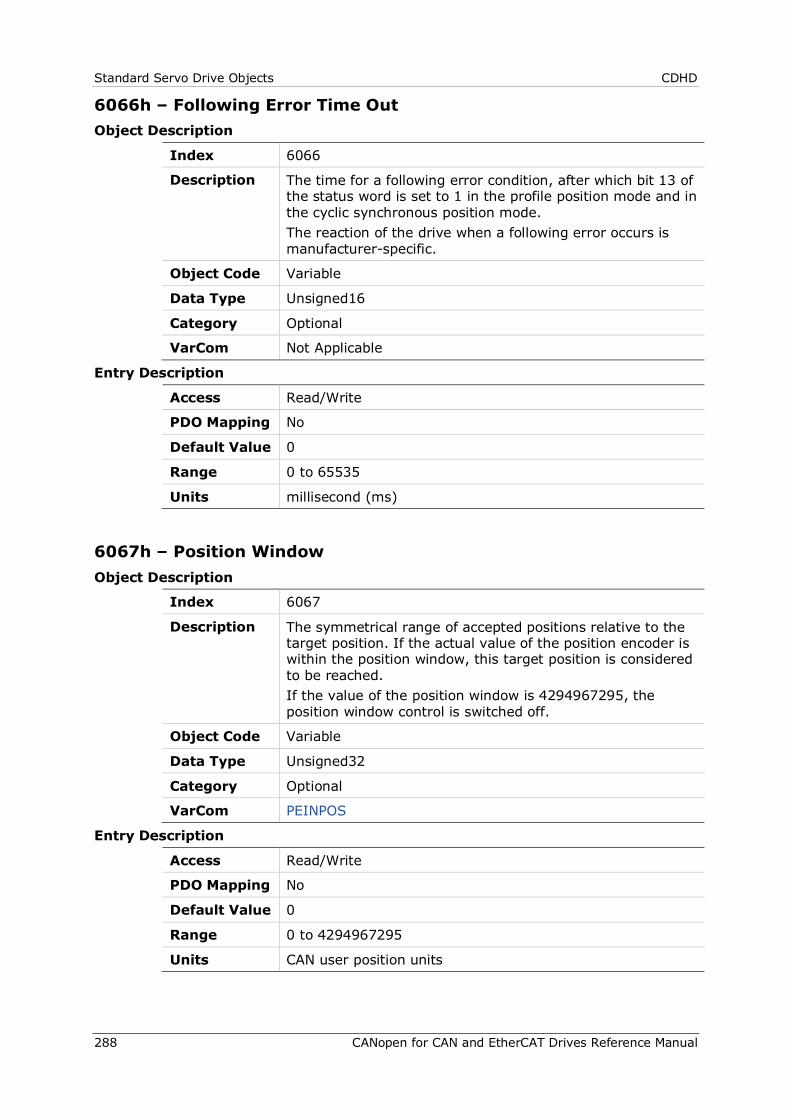
Standard Servo Drive Objects CDHD
288 CANopen for CAN and EtherCAT Drives Reference Manual
6066h – Following Error Time Out Object Description
Index 6066
Description The time for a following error condition, after which bit 13 of the status word is set to 1 in the profile position mode and in the cyclic synchronous position mode. The reaction of the drive when a following error occurs is manufacturer-specific.
Object Code Variable
Data Type Unsigned16
Category Optional
VarCom Not Applicable
Entry Description
Access Read/Write
PDO Mapping No
Default Value 0
Range 0 to 65535
Units millisecond (ms)
6067h – Position Window Object Description
Index 6067
Description The symmetrical range of accepted positions relative to the target position. If the actual value of the position encoder is within the position window, this target position is considered to be reached. If the value of the position window is 4294967295, the position window control is switched off.
Object Code Variable
Data Type Unsigned32
Category Optional
VarCom PEINPOS
Entry Description
Access Read/Write
PDO Mapping No
Default Value 0
Range 0 to 4294967295
Units CAN user position units
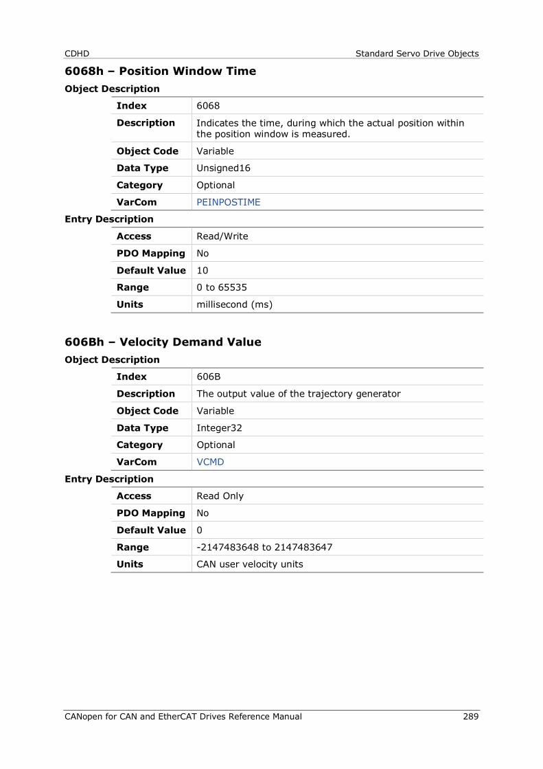
CDHD Standard Servo Drive Objects
CANopen for CAN and EtherCAT Drives Reference Manual 289
6068h – Position Window Time Object Description
Index 6068
Description Indicates the time, during which the actual position within the position window is measured.
Object Code Variable
Data Type Unsigned16
Category Optional
VarCom PEINPOSTIME
Entry Description
Access Read/Write
PDO Mapping No
Default Value 10
Range 0 to 65535
Units millisecond (ms)
606Bh – Velocity Demand Value Object Description
Index 606B
Description The output value of the trajectory generator
Object Code Variable
Data Type Integer32
Category Optional
VarCom VCMD
Entry Description
Access Read Only
PDO Mapping No
Default Value 0
Range -2147483648 to 2147483647
Units CAN user velocity units
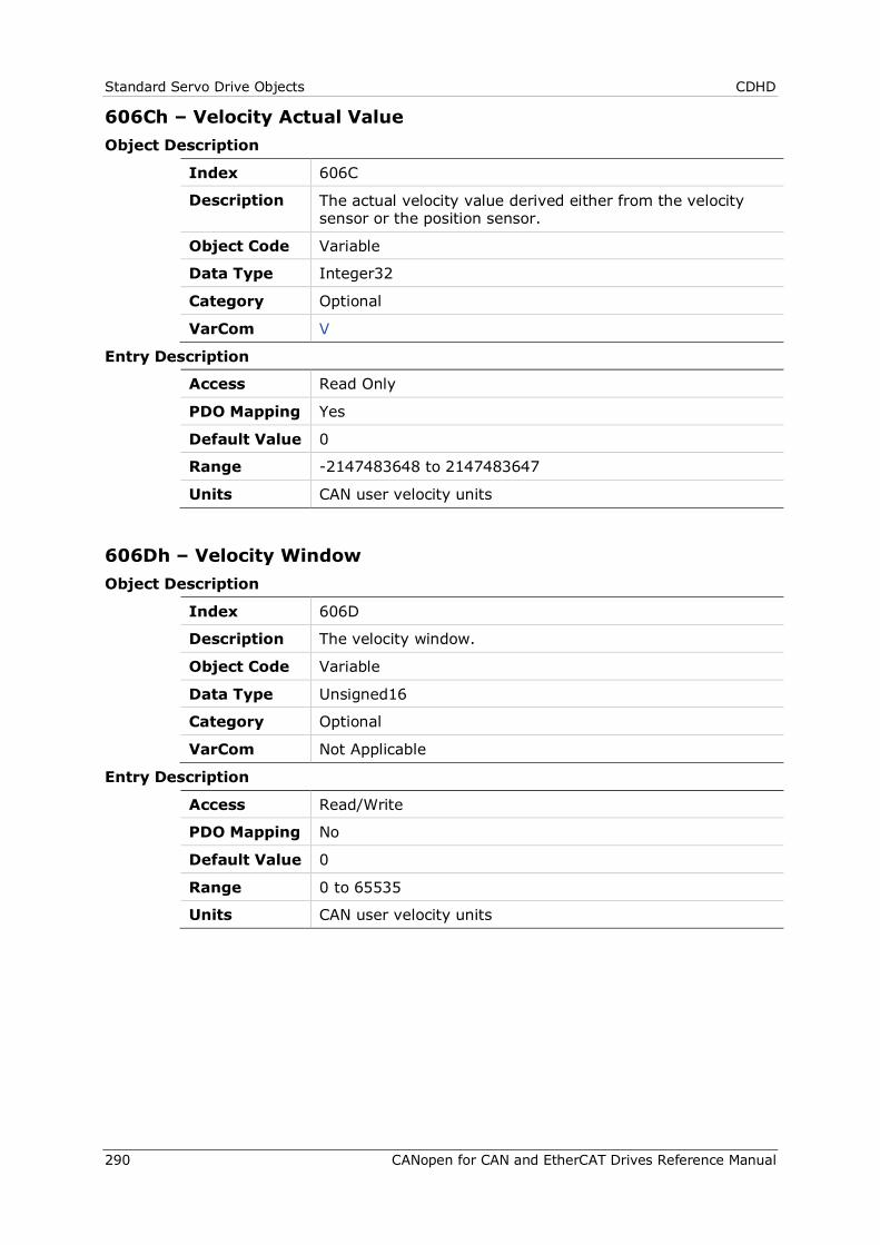
Standard Servo Drive Objects CDHD
290 CANopen for CAN and EtherCAT Drives Reference Manual
606Ch – Velocity Actual Value Object Description
Index 606C
Description The actual velocity value derived either from the velocity sensor or the position sensor.
Object Code Variable
Data Type Integer32
Category Optional
VarCom V
Entry Description
Access Read Only
PDO Mapping Yes
Default Value 0
Range -2147483648 to 2147483647
Units CAN user velocity units
606Dh – Velocity Window Object Description
Index 606D
Description The velocity window.
Object Code Variable
Data Type Unsigned16
Category Optional
VarCom Not Applicable
Entry Description
Access Read/Write
PDO Mapping No
Default Value 0
Range 0 to 65535
Units CAN user velocity units
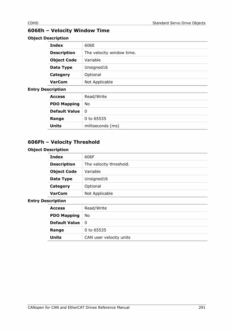
CDHD Standard Servo Drive Objects
CANopen for CAN and EtherCAT Drives Reference Manual 291
606Eh – Velocity Window Time Object Description
Index 606E
Description The velocity window time.
Object Code Variable
Data Type Unsigned16
Category Optional
VarCom Not Applicable
Entry Description
Access Read/Write
PDO Mapping No
Default Value 0
Range 0 to 65535
Units milliseconds (ms)
606Fh – Velocity Threshold Object Description
Index 606F
Description The velocity threshold.
Object Code Variable
Data Type Unsigned16
Category Optional
VarCom Not Applicable
Entry Description
Access Read/Write
PDO Mapping No
Default Value 0
Range 0 to 65535
Units CAN user velocity units
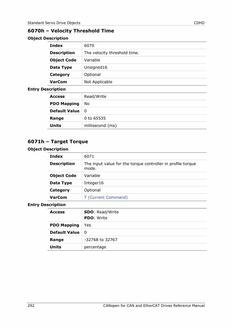
Standard Servo Drive Objects CDHD
292 CANopen for CAN and EtherCAT Drives Reference Manual
6070h – Velocity Threshold Time Object Description
Index 6070
Description The velocity threshold time.
Object Code Variable
Data Type Unsigned16
Category Optional
VarCom Not Applicable
Entry Description
Access Read/Write
PDO Mapping No
Default Value 0
Range 0 to 65535
Units millisecond (ms)
6071h – Target Torque Object Description
Index 6071
Description The input value for the torque controller in profile torque mode.
Object Code Variable
Data Type Integer16
Category Optional
VarCom T (Current Command)
Entry Description
Access SDO: Read/Write PDO: Write
PDO Mapping Yes
Default Value 0
Range -32768 to 32767
Units percentage
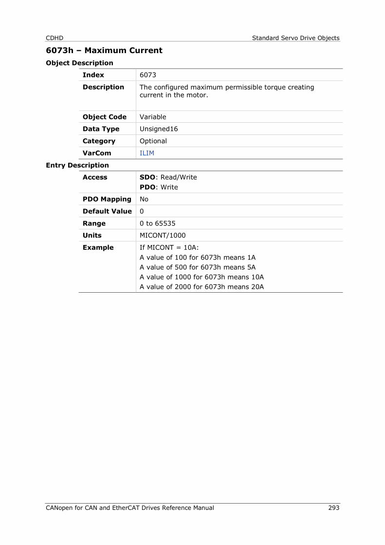
CDHD Standard Servo Drive Objects
CANopen for CAN and EtherCAT Drives Reference Manual 293
6073h – Maximum Current Object Description
Index 6073
Description The configured maximum permissible torque creating current in the motor.
Object Code Variable
Data Type Unsigned16
Category Optional
VarCom ILIM
Entry Description
Access SDO: Read/Write PDO: Write
PDO Mapping No
Default Value 0
Range 0 to 65535
Units MICONT/1000
Example If MICONT = 10A: A value of 100 for 6073h means 1A A value of 500 for 6073h means 5A A value of 1000 for 6073h means 10A A value of 2000 for 6073h means 20A
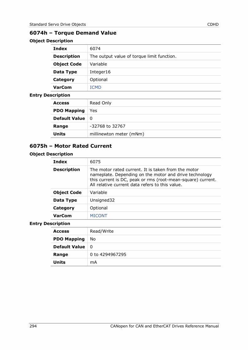
Standard Servo Drive Objects CDHD
294 CANopen for CAN and EtherCAT Drives Reference Manual
6074h – Torque Demand Value Object Description
Index 6074
Description The output value of torque limit function.
Object Code Variable
Data Type Integer16
Category Optional
VarCom ICMD
Entry Description
Access Read Only
PDO Mapping Yes
Default Value 0
Range -32768 to 32767
Units millinewton meter (mNm)
6075h – Motor Rated Current Object Description
Index 6075
Description The motor rated current. It is taken from the motor nameplate. Depending on the motor and drive technology this current is DC, peak or rms (root-mean-square) current. All relative current data refers to this value.
Object Code Variable
Data Type Unsigned32
Category Optional
VarCom MICONT
Entry Description
Access Read/Write
PDO Mapping No
Default Value 0
Range 0 to 4294967295
Units mA
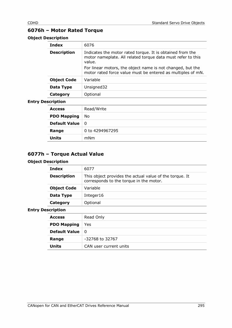
CDHD Standard Servo Drive Objects
CANopen for CAN and EtherCAT Drives Reference Manual 295
6076h – Motor Rated Torque Object Description
Index 6076
Description Indicates the motor rated torque. It is obtained from the motor nameplate. All related torque data must refer to this value. For linear motors, the object name is not changed, but the motor rated force value must be entered as multiples of mN.
Object Code Variable
Data Type Unsigned32
Category Optional
Entry Description
Access Read/Write
PDO Mapping No
Default Value 0
Range 0 to 4294967295
Units mNm
6077h – Torque Actual Value Object Description
Index 6077
Description This object provides the actual value of the torque. It corresponds to the torque in the motor.
Object Code Variable
Data Type Integer16
Category Optional
Entry Description
Access Read Only
PDO Mapping Yes
Default Value 0
Range -32768 to 32767
Units CAN user current units
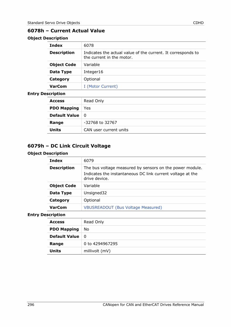
Standard Servo Drive Objects CDHD
296 CANopen for CAN and EtherCAT Drives Reference Manual
6078h – Current Actual Value Object Description
Index 6078
Description Indicates the actual value of the current. It corresponds to the current in the motor.
Object Code Variable
Data Type Integer16
Category Optional
VarCom I (Motor Current)
Entry Description
Access Read Only
PDO Mapping Yes
Default Value 0
Range -32768 to 32767
Units CAN user current units
6079h – DC Link Circuit Voltage Object Description
Index 6079
Description The bus voltage measured by sensors on the power module. Indicates the instantaneous DC link current voltage at the drive device.
Object Code Variable
Data Type Unsigned32
Category Optional
VarCom VBUSREADOUT (Bus Voltage Measured)
Entry Description
Access Read Only
PDO Mapping No
Default Value 0
Range 0 to 4294967295
Units millivolt (mV)
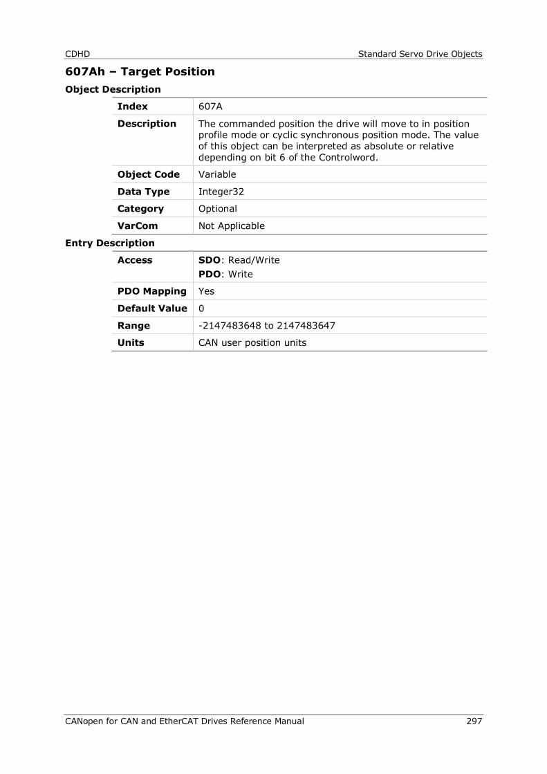
CDHD Standard Servo Drive Objects
CANopen for CAN and EtherCAT Drives Reference Manual 297
607Ah – Target Position Object Description
Index 607A
Description The commanded position the drive will move to in position profile mode or cyclic synchronous position mode. The value of this object can be interpreted as absolute or relative depending on bit 6 of the Controlword.
Object Code Variable
Data Type Integer32
Category Optional
VarCom Not Applicable
Entry Description
Access SDO: Read/Write PDO: Write
PDO Mapping Yes
Default Value 0
Range -2147483648 to 2147483647
Units CAN user position units
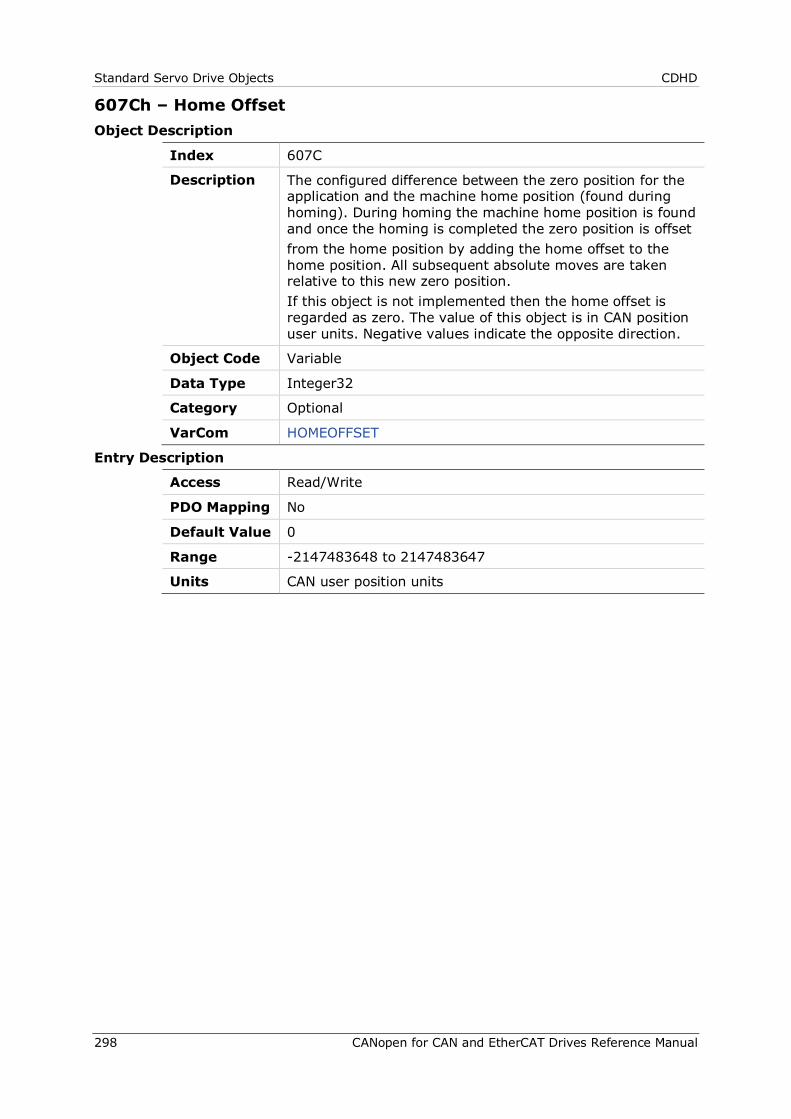
Standard Servo Drive Objects CDHD
298 CANopen for CAN and EtherCAT Drives Reference Manual
607Ch – Home Offset Object Description
Index 607C
Description The configured difference between the zero position for the application and the machine home position (found during homing). During homing the machine home position is found and once the homing is completed the zero position is offset from the home position by adding the home offset to the home position. All subsequent absolute moves are taken relative to this new zero position. If this object is not implemented then the home offset is regarded as zero. The value of this object is in CAN position user units. Negative values indicate the opposite direction.
Object Code Variable
Data Type Integer32
Category Optional
VarCom HOMEOFFSET
Entry Description
Access Read/Write
PDO Mapping No
Default Value 0
Range -2147483648 to 2147483647
Units CAN user position units
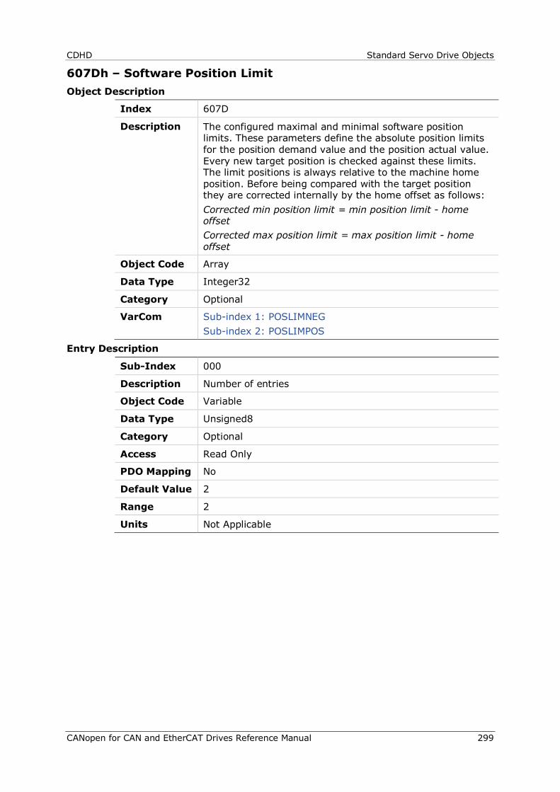
CDHD Standard Servo Drive Objects
CANopen for CAN and EtherCAT Drives Reference Manual 299
607Dh – Software Position Limit Object Description
Index 607D
Description The configured maximal and minimal software position limits. These parameters define the absolute position limits for the position demand value and the position actual value. Every new target position is checked against these limits. The limit positions is always relative to the machine home position. Before being compared with the target position they are corrected internally by the home offset as follows: Corrected min position limit = min position limit - home offset Corrected max position limit = max position limit - home offset
Object Code Array
Data Type Integer32
Category Optional
VarCom Sub-index 1: POSLIMNEG Sub-index 2: POSLIMPOS
Entry Description
Sub-Index 000
Description Number of entries
Object Code Variable
Data Type Unsigned8
Category Optional
Access Read Only
PDO Mapping No
Default Value 2
Range 2
Units Not Applicable
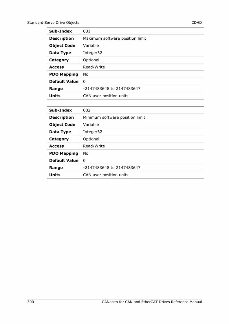
Standard Servo Drive Objects CDHD
300 CANopen for CAN and EtherCAT Drives Reference Manual
Sub-Index 001
Description Maximum software position limit
Object Code Variable
Data Type Integer32
Category Optional
Access Read/Write
PDO Mapping No
Default Value 0
Range -2147483648 to 2147483647
Units CAN user position units
Sub-Index 002
Description Minimum software position limit
Object Code Variable
Data Type Integer32
Category Optional
Access Read/Write
PDO Mapping No
Default Value 0
Range -2147483648 to 2147483647
Units CAN user position units
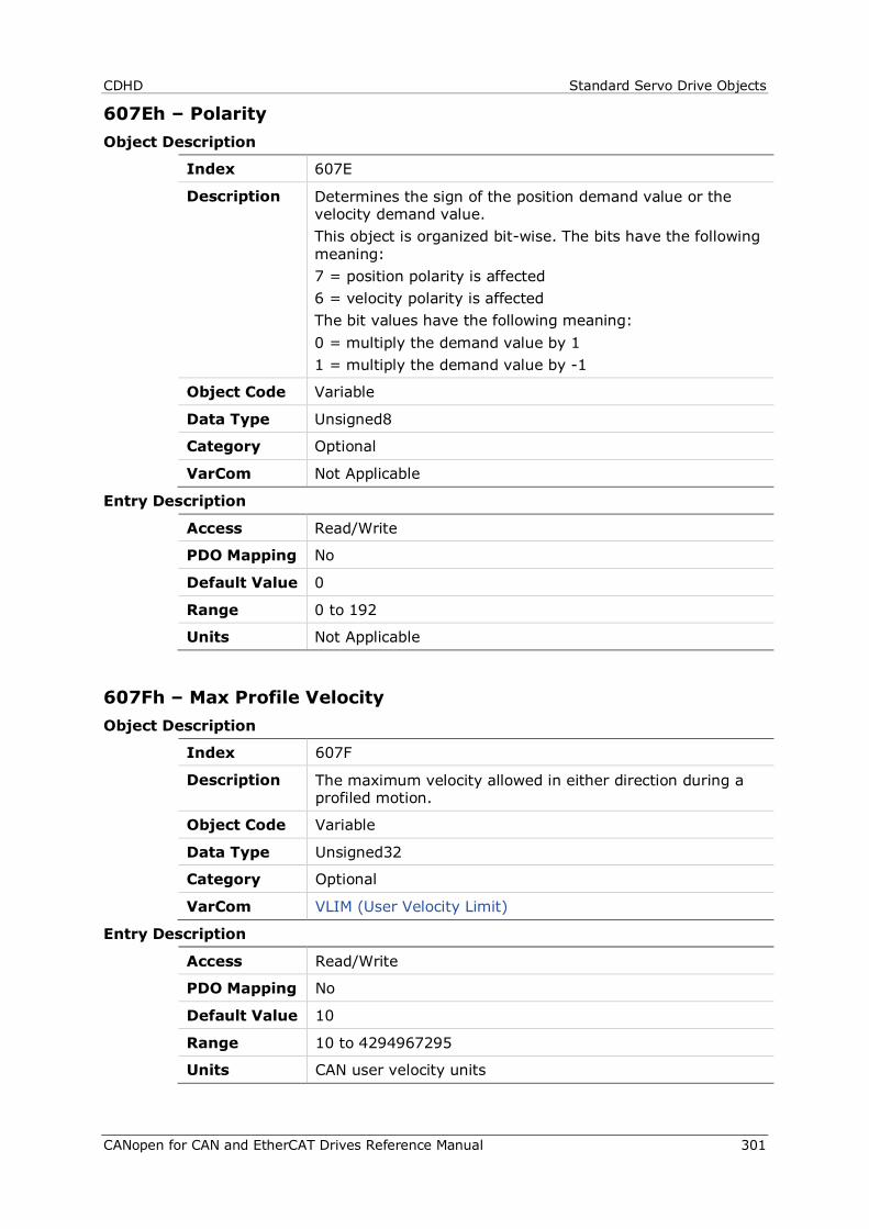
CDHD Standard Servo Drive Objects
CANopen for CAN and EtherCAT Drives Reference Manual 301
607Eh – Polarity Object Description
Index 607E
Description Determines the sign of the position demand value or the velocity demand value. This object is organized bit-wise. The bits have the following meaning: 7 = position polarity is affected 6 = velocity polarity is affected The bit values have the following meaning: 0 = multiply the demand value by 1 1 = multiply the demand value by -1
Object Code Variable
Data Type Unsigned8
Category Optional
VarCom Not Applicable
Entry Description
Access Read/Write
PDO Mapping No
Default Value 0
Range 0 to 192
Units Not Applicable
607Fh – Max Profile Velocity Object Description
Index 607F
Description The maximum velocity allowed in either direction during a profiled motion.
Object Code Variable
Data Type Unsigned32
Category Optional
VarCom VLIM (User Velocity Limit)
Entry Description
Access Read/Write
PDO Mapping No
Default Value 10
Range 10 to 4294967295
Units CAN user velocity units
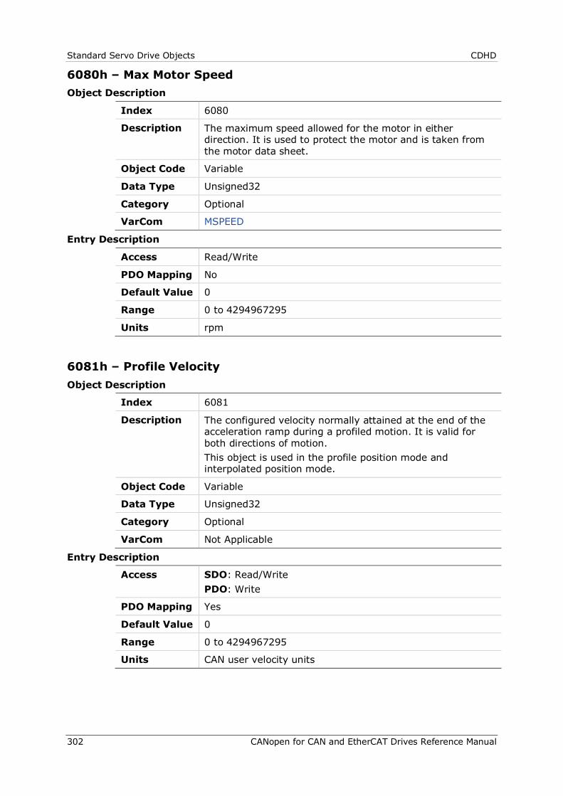
Standard Servo Drive Objects CDHD
302 CANopen for CAN and EtherCAT Drives Reference Manual
6080h – Max Motor Speed Object Description
Index 6080
Description The maximum speed allowed for the motor in either direction. It is used to protect the motor and is taken from the motor data sheet.
Object Code Variable
Data Type Unsigned32
Category Optional
VarCom MSPEED
Entry Description
Access Read/Write
PDO Mapping No
Default Value 0
Range 0 to 4294967295
Units rpm
6081h – Profile Velocity Object Description
Index 6081
Description The configured velocity normally attained at the end of the acceleration ramp during a profiled motion. It is valid for both directions of motion. This object is used in the profile position mode and interpolated position mode.
Object Code Variable
Data Type Unsigned32
Category Optional
VarCom Not Applicable
Entry Description
Access SDO: Read/Write PDO: Write
PDO Mapping Yes
Default Value 0
Range 0 to 4294967295
Units CAN user velocity units
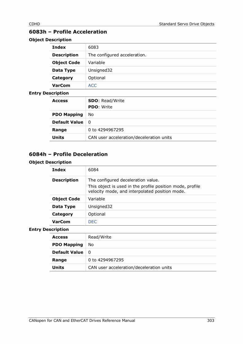
CDHD Standard Servo Drive Objects
CANopen for CAN and EtherCAT Drives Reference Manual 303
6083h – Profile Acceleration Object Description
Index 6083
Description The configured acceleration.
Object Code Variable
Data Type Unsigned32
Category Optional
VarCom ACC
Entry Description
Access SDO: Read/Write PDO: Write
PDO Mapping No
Default Value 0
Range 0 to 4294967295
Units CAN user acceleration/deceleration units
6084h – Profile Deceleration Object Description
Index 6084
Description The configured deceleration value. This object is used in the profile position mode, profile velocity mode, and interpolated position mode.
Object Code Variable
Data Type Unsigned32
Category Optional
VarCom DEC
Entry Description
Access Read/Write
PDO Mapping No
Default Value 0
Range 0 to 4294967295
Units CAN user acceleration/deceleration units
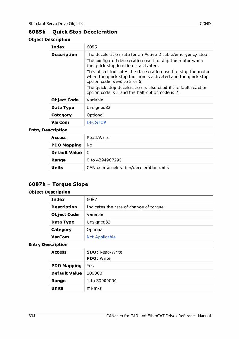
Standard Servo Drive Objects CDHD
304 CANopen for CAN and EtherCAT Drives Reference Manual
6085h – Quick Stop Deceleration Object Description
Index 6085
Description The deceleration rate for an Active Disable/emergency stop. The configured deceleration used to stop the motor when the quick stop function is activated. This object indicates the deceleration used to stop the motor when the quick stop function is activated and the quick stop option code is set to 2 or 6. The quick stop deceleration is also used if the fault reaction option code is 2 and the halt option code is 2.
Object Code Variable
Data Type Unsigned32
Category Optional
VarCom DECSTOP
Entry Description
Access Read/Write
PDO Mapping No
Default Value 0
Range 0 to 4294967295
Units CAN user acceleration/deceleration units
6087h – Torque Slope Object Description
Index 6087
Description Indicates the rate of change of torque.
Object Code Variable
Data Type Unsigned32
Category Optional
VarCom Not Applicable
Entry Description
Access SDO: Read/Write PDO: Write
PDO Mapping Yes
Default Value 100000
Range 1 to 30000000
Units mNm/s
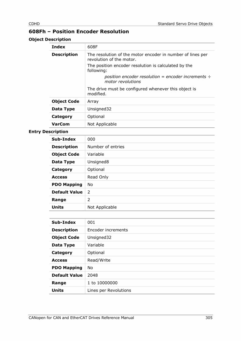
CDHD Standard Servo Drive Objects
CANopen for CAN and EtherCAT Drives Reference Manual 305
608Fh – Position Encoder Resolution Object Description
Index 608F
Description The resolution of the motor encoder in number of lines per revolution of the motor. The position encoder resolution is calculated by the following:
position encoder resolution = encoder increments ÷ motor revolutions
The drive must be configured whenever this object is modified.
Object Code Array
Data Type Unsigned32
Category Optional
VarCom Not Applicable
Entry Description
Sub-Index 000
Description Number of entries
Object Code Variable
Data Type Unsigned8
Category Optional
Access Read Only
PDO Mapping No
Default Value 2
Range 2
Units Not Applicable
Sub-Index 001
Description Encoder increments
Object Code Unsigned32
Data Type Variable
Category Optional
Access Read/Write
PDO Mapping No
Default Value 2048
Range 1 to 10000000
Units Lines per Revolutions
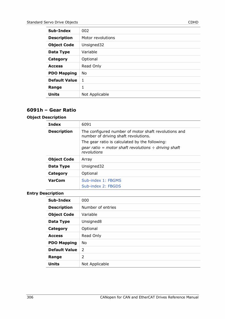
Standard Servo Drive Objects CDHD
306 CANopen for CAN and EtherCAT Drives Reference Manual
Sub-Index 002
Description Motor revolutions
Object Code Unsigned32
Data Type Variable
Category Optional
Access Read Only
PDO Mapping No
Default Value 1
Range 1
Units Not Applicable
6091h – Gear Ratio Object Description
Index 6091
Description The configured number of motor shaft revolutions and number of driving shaft revolutions. The gear ratio is calculated by the following: gear ratio = motor shaft revolutions ÷ driving shaft revolutions
Object Code Array
Data Type Unsigned32
Category Optional
VarCom Sub-index 1: FBGMS Sub-index 2: FBGDS
Entry Description
Sub-Index 000
Description Number of entries
Object Code Variable
Data Type Unsigned8
Category Optional
Access Read Only
PDO Mapping No
Default Value 2
Range 2
Units Not Applicable

CDHD Standard Servo Drive Objects
CANopen for CAN and EtherCAT Drives Reference Manual 307
Sub-Index 001
Description Motor revolutions
Object Code Variable
Data Type Unsigned32
Category Optional
Access Read/Write
PDO Mapping No
Default Value 1
Range 1 to 4294967295
Units Not Applicable
Sub-Index 002
Description Shaft revolutions
Object Code Variable
Data Type Unsigned32
Category Optional
Access Read/Write
PDO Mapping No
Default Value 1
Range 1 to 4294967295
Units Not Applicable
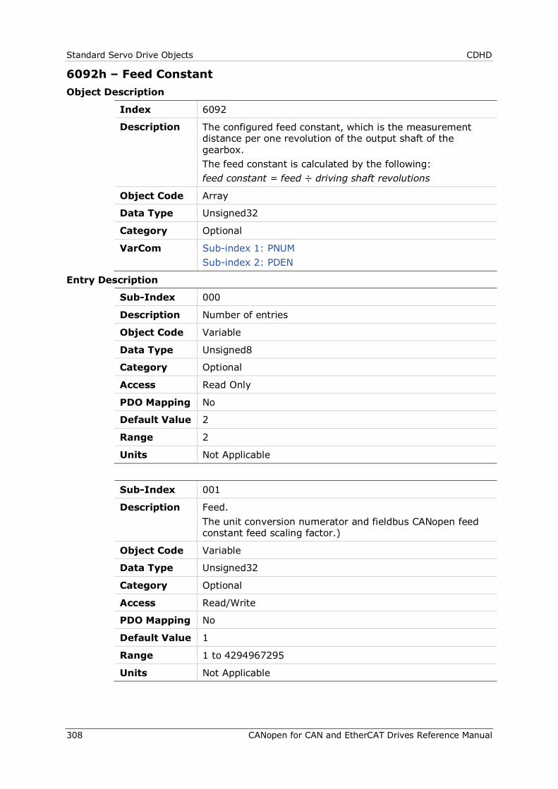
Standard Servo Drive Objects CDHD
308 CANopen for CAN and EtherCAT Drives Reference Manual
6092h – Feed Constant Object Description
Index 6092
Description The configured feed constant, which is the measurement distance per one revolution of the output shaft of the gearbox. The feed constant is calculated by the following: feed constant = feed ÷ driving shaft revolutions
Object Code Array
Data Type Unsigned32
Category Optional
VarCom Sub-index 1: PNUM Sub-index 2: PDEN
Entry Description
Sub-Index 000
Description Number of entries
Object Code Variable
Data Type Unsigned8
Category Optional
Access Read Only
PDO Mapping No
Default Value 2
Range 2
Units Not Applicable
Sub-Index 001
Description Feed. The unit conversion numerator and fieldbus CANopen feed constant feed scaling factor.)
Object Code Variable
Data Type Unsigned32
Category Optional
Access Read/Write
PDO Mapping No
Default Value 1
Range 1 to 4294967295
Units Not Applicable
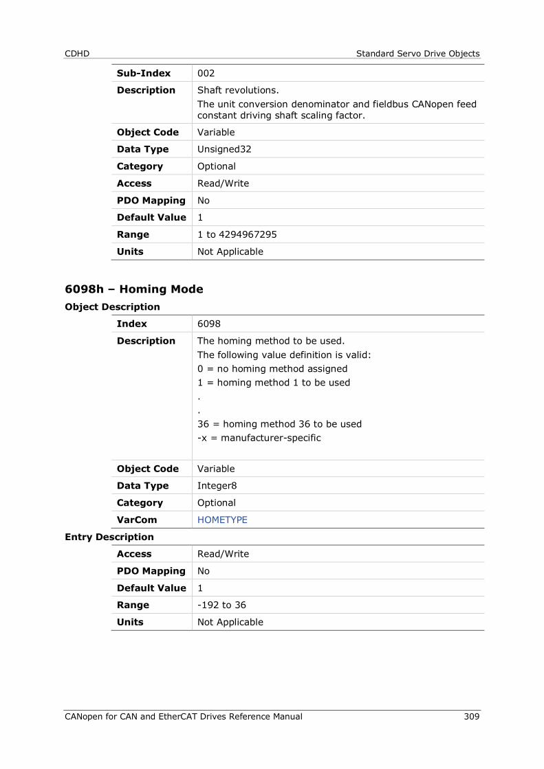
CDHD Standard Servo Drive Objects
CANopen for CAN and EtherCAT Drives Reference Manual 309
Sub-Index 002
Description Shaft revolutions. The unit conversion denominator and fieldbus CANopen feed constant driving shaft scaling factor.
Object Code Variable
Data Type Unsigned32
Category Optional
Access Read/Write
PDO Mapping No
Default Value 1
Range 1 to 4294967295
Units Not Applicable
6098h – Homing Mode Object Description
Index 6098
Description The homing method to be used. The following value definition is valid: 0 = no homing method assigned 1 = homing method 1 to be used . . 36 = homing method 36 to be used -x = manufacturer-specific
Object Code Variable
Data Type Integer8
Category Optional
VarCom HOMETYPE
Entry Description
Access Read/Write
PDO Mapping No
Default Value 1
Range -192 to 36
Units Not Applicable
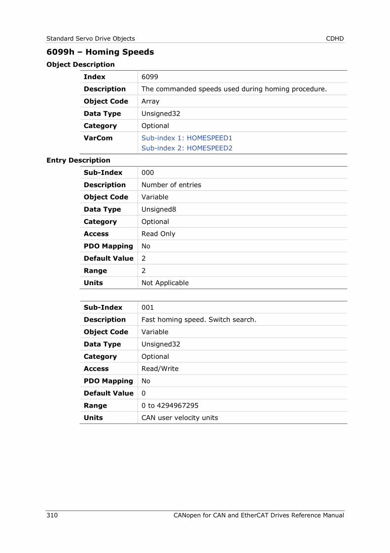
Standard Servo Drive Objects CDHD
310 CANopen for CAN and EtherCAT Drives Reference Manual
6099h – Homing Speeds Object Description
Index 6099
Description The commanded speeds used during homing procedure.
Object Code Array
Data Type Unsigned32
Category Optional
VarCom Sub-index 1: HOMESPEED1 Sub-index 2: HOMESPEED2
Entry Description
Sub-Index 000
Description Number of entries
Object Code Variable
Data Type Unsigned8
Category Optional
Access Read Only
PDO Mapping No
Default Value 2
Range 2
Units Not Applicable
Sub-Index 001
Description Fast homing speed. Switch search.
Object Code Variable
Data Type Unsigned32
Category Optional
Access Read/Write
PDO Mapping No
Default Value 0
Range 0 to 4294967295
Units CAN user velocity units
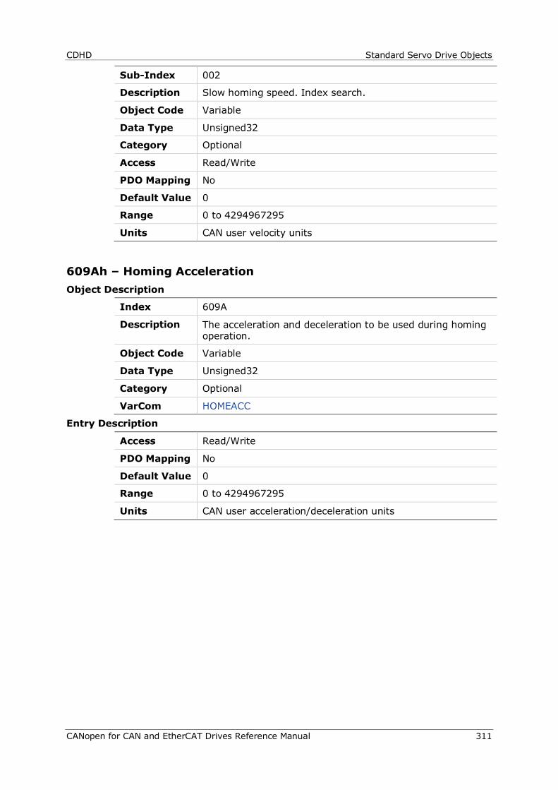
CDHD Standard Servo Drive Objects
CANopen for CAN and EtherCAT Drives Reference Manual 311
Sub-Index 002
Description Slow homing speed. Index search.
Object Code Variable
Data Type Unsigned32
Category Optional
Access Read/Write
PDO Mapping No
Default Value 0
Range 0 to 4294967295
Units CAN user velocity units
609Ah – Homing Acceleration Object Description
Index 609A
Description The acceleration and deceleration to be used during homing operation.
Object Code Variable
Data Type Unsigned32
Category Optional
VarCom HOMEACC
Entry Description
Access Read/Write
PDO Mapping No
Default Value 0
Range 0 to 4294967295
Units CAN user acceleration/deceleration units
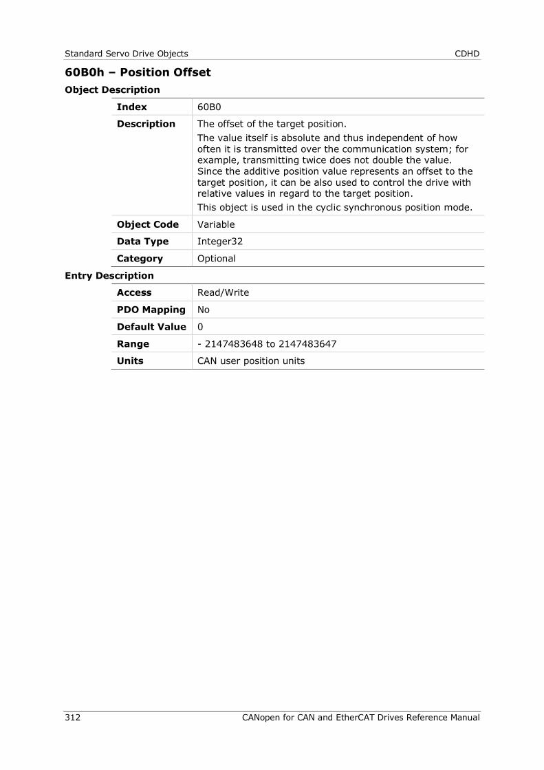
Standard Servo Drive Objects CDHD
312 CANopen for CAN and EtherCAT Drives Reference Manual
60B0h – Position Offset Object Description
Index 60B0
Description The offset of the target position. The value itself is absolute and thus independent of how often it is transmitted over the communication system; for example, transmitting twice does not double the value. Since the additive position value represents an offset to the target position, it can be also used to control the drive with relative values in regard to the target position. This object is used in the cyclic synchronous position mode.
Object Code Variable
Data Type Integer32
Category Optional
Entry Description
Access Read/Write
PDO Mapping No
Default Value 0
Range - 2147483648 to 2147483647
Units CAN user position units
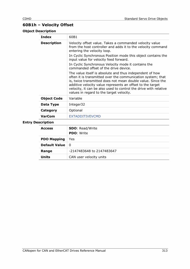
CDHD Standard Servo Drive Objects
CANopen for CAN and EtherCAT Drives Reference Manual 313
60B1h – Velocity Offset Object Description
Index 60B1
Description Velocity offset value. Takes a commanded velocity value from the host controller and adds it to the velocity command entering the velocity loop. In Cyclic Synchronous Position mode this object contains the input value for velocity feed forward. In Cyclic Synchronous Velocity mode it contains the commanded offset of the drive device. The value itself is absolute and thus independent of how often it is transmitted over the communication system; that is, twice transmitted does not mean double value. Since the additive velocity value represents an offset to the target velocity, it can be also used to control the drive with relative values in regard to the target velocity.
Object Code Variable
Data Type Integer32
Category Optional
VarCom EXTADDITIVEVCMD
Entry Description
Access SDO: Read/Write PDO: Write
PDO Mapping Yes
Default Value 0
Range -2147483648 to 2147483647
Units CAN user velocity units
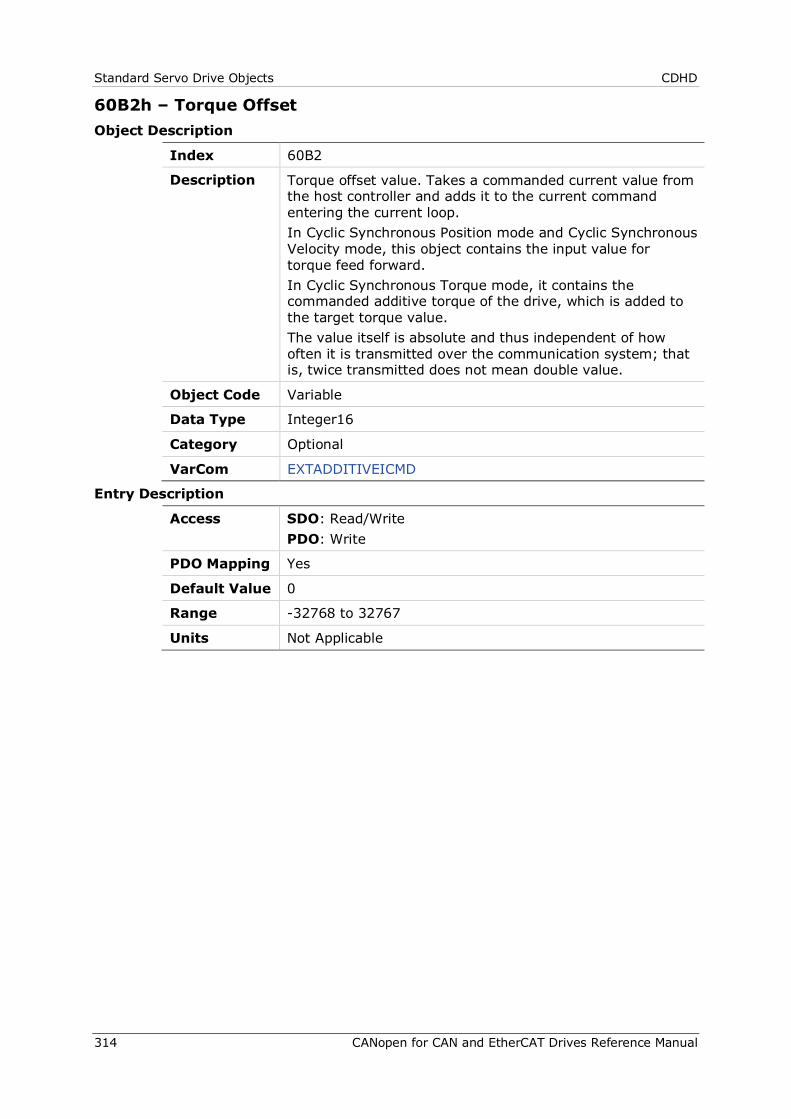
Standard Servo Drive Objects CDHD
314 CANopen for CAN and EtherCAT Drives Reference Manual
60B2h – Torque Offset Object Description
Index 60B2
Description Torque offset value. Takes a commanded current value from the host controller and adds it to the current command entering the current loop. In Cyclic Synchronous Position mode and Cyclic Synchronous Velocity mode, this object contains the input value for torque feed forward. In Cyclic Synchronous Torque mode, it contains the commanded additive torque of the drive, which is added to the target torque value. The value itself is absolute and thus independent of how often it is transmitted over the communication system; that is, twice transmitted does not mean double value.
Object Code Variable
Data Type Integer16
Category Optional
VarCom EXTADDITIVEICMD
Entry Description
Access SDO: Read/Write PDO: Write
PDO Mapping Yes
Default Value 0
Range -32768 to 32767
Units Not Applicable
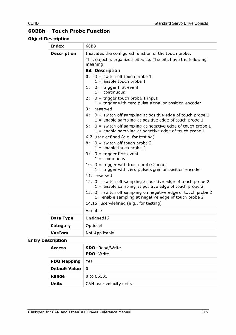
CDHD Standard Servo Drive Objects
CANopen for CAN and EtherCAT Drives Reference Manual 315
60B8h – Touch Probe Function Object Description
Index 60B8
Description Indicates the configured function of the touch probe. This object is organized bit-wise. The bits have the following meaning: Bit Description 0: 0 = switch off touch probe 1
1 = enable touch probe 1 1: 0 = trigger first event
1 = continuous 2: 0 = trigger touch probe 1 input
1 = trigger with zero pulse signal or position encoder 3: reserved 4: 0 = switch off sampling at positive edge of touch probe 1
1 = enable sampling at positive edge of touch probe 1 5: 0 = switch off sampling at negative edge of touch probe 1
1 = enable sampling at negative edge of touch probe 1 6,7: user-defined (e.g. for testing) 8: 0 = switch off touch probe 2
1 = enable touch probe 2 9: 0 = trigger first event
1 = continuous 10: 0 = trigger with touch probe 2 input
1 = trigger with zero pulse signal or position encoder 11: reserved 12: 0 = switch off sampling at positive edge of touch probe 2
1 = enable sampling at positive edge of touch probe 2 13: 0 = switch off sampling on negative edge of touch probe 2
1 =enable sampling at negative edge of touch probe 2 14,15: user-defined (e.g., for testing)
Variable
Data Type Unsigned16
Category Optional
VarCom Not Applicable
Entry Description
Access SDO: Read/Write PDO: Write
PDO Mapping Yes
Default Value 0
Range 0 to 65535
Units CAN user velocity units

Standard Servo Drive Objects CDHD
316 CANopen for CAN and EtherCAT Drives Reference Manual
60B9h – Touch Probe Status Object Description
Index 60B9
Description Indicates the status of the touch probe. This object is organized bit-wise. The bits have the following meaning: Bit Description 0: 0 = touch probe 1 is switched off
1 = touch probe 1 is enabled 1: 0 = touch probe 1 no positive edge value stored
1 = touch probe 1 negative edge position stored 2: 0 = touch probe 1 no negative edge value stored
1 = touch probe 1 positive edge position stored 3-5: reserved 6,7: user-defined (e.g. for testing) 8: 0 = touch probe 2 is switched off
1 =touch probe 2 is enabled 9: 0 = touch probe 2 no positive edge value stored
1 = touch probe 2 negative edge position stored 10: 0 = touch probe 2 no negative edge value stored
1 = touch probe 2 positive edge position stored 11-13: reserved 14,15: user-defined (e.g. for testing)
Object Code Variable
Data Type Unsigned16
Category Optional
VarCom Not Applicable
Entry Description
Access Read Only
PDO Mapping Yes
Default Value 0
Range 0 to 65535
Units Not Applicable
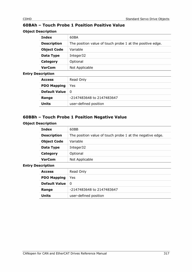
CDHD Standard Servo Drive Objects
CANopen for CAN and EtherCAT Drives Reference Manual 317
60BAh – Touch Probe 1 Position Positive Value Object Description
Index 60BA
Description The position value of touch probe 1 at the positive edge.
Object Code Variable
Data Type Integer32
Category Optional
VarCom Not Applicable
Entry Description
Access Read Only
PDO Mapping Yes
Default Value 0
Range -2147483648 to 2147483647
Units user-defined position
60BBh – Touch Probe 1 Position Negative Value Object Description
Index 60BB
Description The position value of touch probe 1 at the negative edge.
Object Code Variable
Data Type Integer32
Category Optional
VarCom Not Applicable
Entry Description
Access Read Only
PDO Mapping Yes
Default Value 0
Range -2147483648 to 2147483647
Units user-defined position
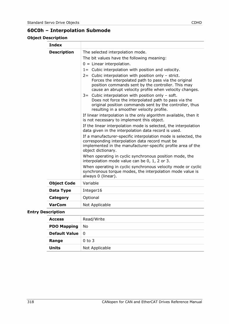
Standard Servo Drive Objects CDHD
318 CANopen for CAN and EtherCAT Drives Reference Manual
60C0h – Interpolation Submode Object Description
Index
Description The selected interpolation mode. The bit values have the following meaning: 0 = Linear interpolation. 1= Cubic interpolation with position and velocity. 2= Cubic interpolation with position only – strict.
Forces the interpolated path to pass via the original position commands sent by the controller. This may cause an abrupt velocity profile when velocity changes.
3= Cubic interpolation with position only – soft. Does not force the interpolated path to pass via the original position commands sent by the controller, thus resulting in a smoother velocity profile.
If linear interpolation is the only algorithm available, then it is not necessary to implement this object. If the linear interpolation mode is selected, the interpolation data given in the interpolation data record is used. If a manufacturer-specific interpolation mode is selected, the corresponding interpolation data record must be implemented in the manufacturer-specific profile area of the object dictionary. When operating in cyclic synchronous position mode, the interpolation mode value can be 0, 1, 2 or 3. When operating in cyclic synchronous velocity mode or cyclic synchronous torque modes, the interpolation mode value is always 0 (linear).
Object Code Variable
Data Type Integer16
Category Optional
VarCom Not Applicable
Entry Description
Access Read/Write
PDO Mapping No
Default Value 0
Range 0 to 3
Units Not Applicable
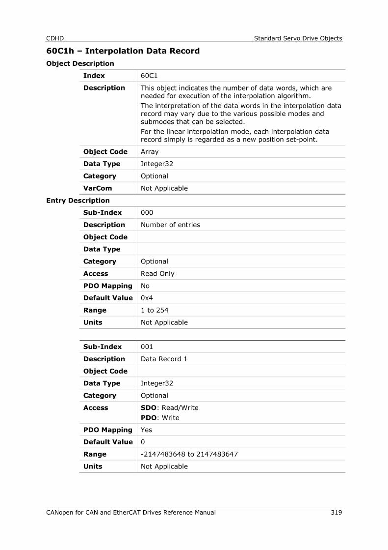
CDHD Standard Servo Drive Objects
CANopen for CAN and EtherCAT Drives Reference Manual 319
60C1h – Interpolation Data Record Object Description
Index 60C1
Description This object indicates the number of data words, which are needed for execution of the interpolation algorithm. The interpretation of the data words in the interpolation data record may vary due to the various possible modes and submodes that can be selected. For the linear interpolation mode, each interpolation data record simply is regarded as a new position set-point.
Object Code Array
Data Type Integer32
Category Optional
VarCom Not Applicable
Entry Description
Sub-Index 000
Description Number of entries
Object Code
Data Type
Category Optional
Access Read Only
PDO Mapping No
Default Value 0x4
Range 1 to 254
Units Not Applicable
Sub-Index 001
Description Data Record 1
Object Code
Data Type Integer32
Category Optional
Access SDO: Read/Write PDO: Write
PDO Mapping Yes
Default Value 0
Range -2147483648 to 2147483647
Units Not Applicable
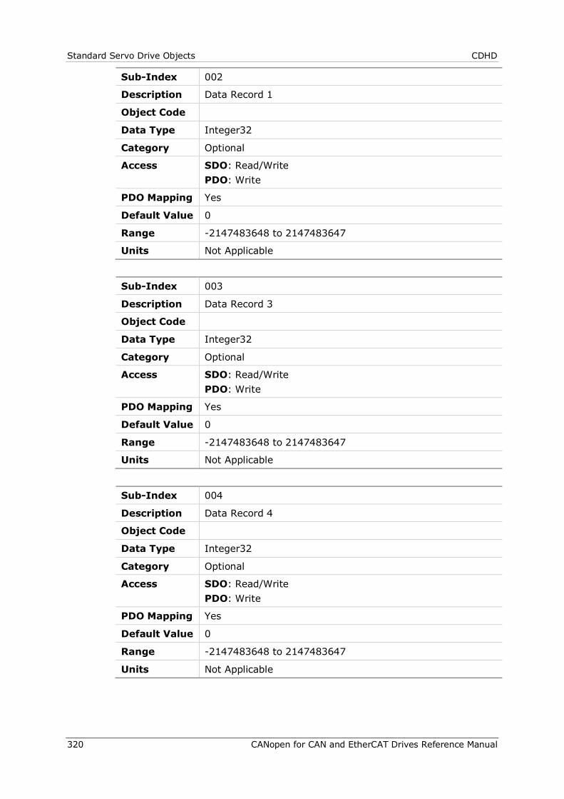
Standard Servo Drive Objects CDHD
320 CANopen for CAN and EtherCAT Drives Reference Manual
Sub-Index 002
Description Data Record 1
Object Code
Data Type Integer32
Category Optional
Access SDO: Read/Write PDO: Write
PDO Mapping Yes
Default Value 0
Range -2147483648 to 2147483647
Units Not Applicable
Sub-Index 003
Description Data Record 3
Object Code
Data Type Integer32
Category Optional
Access SDO: Read/Write PDO: Write
PDO Mapping Yes
Default Value 0
Range -2147483648 to 2147483647
Units Not Applicable
Sub-Index 004
Description Data Record 4
Object Code
Data Type Integer32
Category Optional
Access SDO: Read/Write PDO: Write
PDO Mapping Yes
Default Value 0
Range -2147483648 to 2147483647
Units Not Applicable
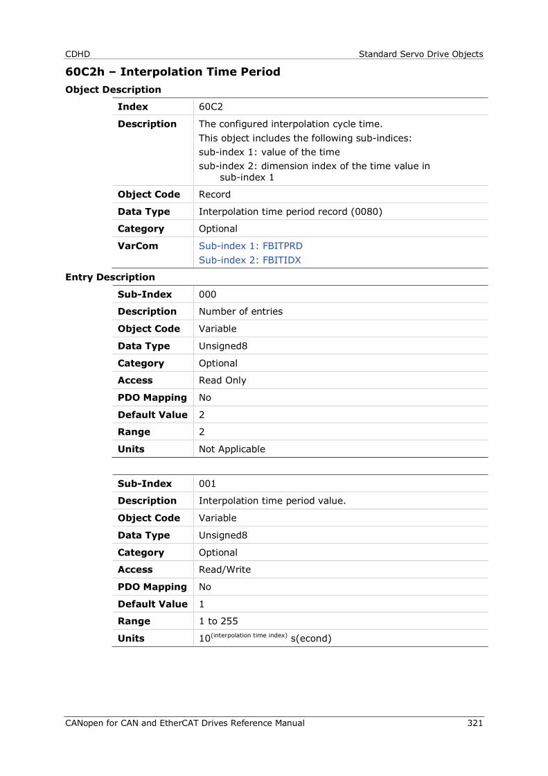
CDHD Standard Servo Drive Objects
CANopen for CAN and EtherCAT Drives Reference Manual 321
60C2h – Interpolation Time Period Object Description
Index 60C2
Description The configured interpolation cycle time. This object includes the following sub-indices: sub-index 1: value of the time sub-index 2: dimension index of the time value in
sub-index 1
Object Code Record
Data Type Interpolation time period record (0080)
Category Optional
VarCom Sub-index 1: FBITPRD Sub-index 2: FBITIDX
Entry Description
Sub-Index 000
Description Number of entries
Object Code Variable
Data Type Unsigned8
Category Optional
Access Read Only
PDO Mapping No
Default Value 2
Range 2
Units Not Applicable
Sub-Index 001
Description Interpolation time period value.
Object Code Variable
Data Type Unsigned8
Category Optional
Access Read/Write
PDO Mapping No
Default Value 1
Range 1 to 255
Units 10(interpolation time index) s(econd)
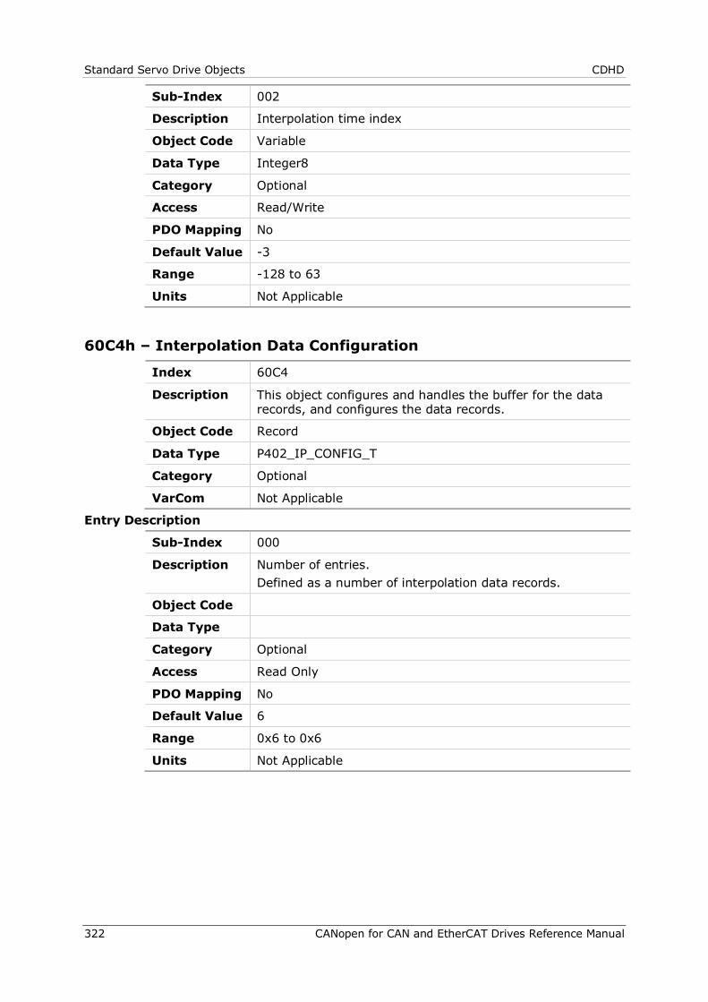
Standard Servo Drive Objects CDHD
322 CANopen for CAN and EtherCAT Drives Reference Manual
Sub-Index 002
Description Interpolation time index
Object Code Variable
Data Type Integer8
Category Optional
Access Read/Write
PDO Mapping No
Default Value -3
Range -128 to 63
Units Not Applicable
60C4h – Interpolation Data Configuration
Index 60C4
Description This object configures and handles the buffer for the data records, and configures the data records.
Object Code Record
Data Type P402_IP_CONFIG_T
Category Optional
VarCom Not Applicable
Entry Description
Sub-Index 000
Description Number of entries. Defined as a number of interpolation data records.
Object Code
Data Type
Category Optional
Access Read Only
PDO Mapping No
Default Value 6
Range 0x6 to 0x6
Units Not Applicable
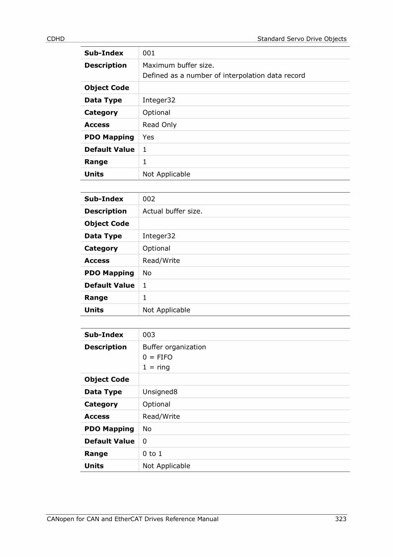
CDHD Standard Servo Drive Objects
CANopen for CAN and EtherCAT Drives Reference Manual 323
Sub-Index 001
Description Maximum buffer size. Defined as a number of interpolation data record
Object Code
Data Type Integer32
Category Optional
Access Read Only
PDO Mapping Yes
Default Value 1
Range 1
Units Not Applicable
Sub-Index 002
Description Actual buffer size.
Object Code
Data Type Integer32
Category Optional
Access Read/Write
PDO Mapping No
Default Value 1
Range 1
Units Not Applicable
Sub-Index 003
Description Buffer organization 0 = FIFO 1 = ring
Object Code
Data Type Unsigned8
Category Optional
Access Read/Write
PDO Mapping No
Default Value 0
Range 0 to 1
Units Not Applicable
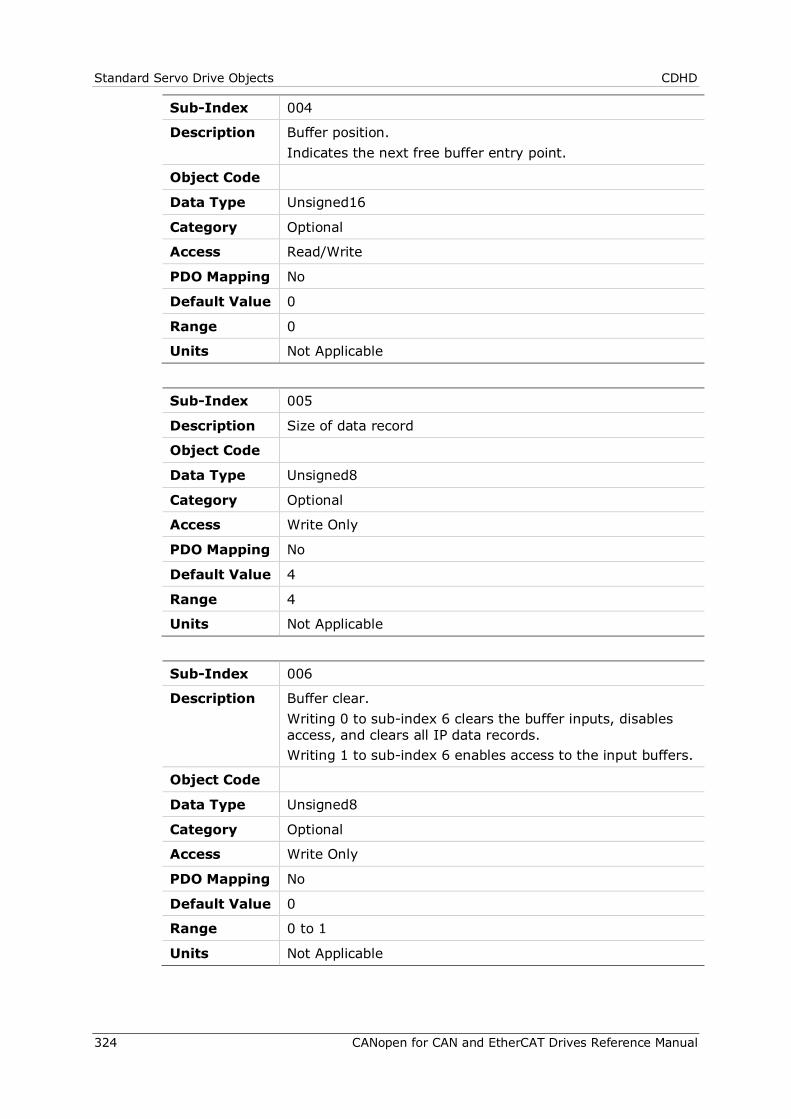
Standard Servo Drive Objects CDHD
324 CANopen for CAN and EtherCAT Drives Reference Manual
Sub-Index 004
Description Buffer position. Indicates the next free buffer entry point.
Object Code
Data Type Unsigned16
Category Optional
Access Read/Write
PDO Mapping No
Default Value 0
Range 0
Units Not Applicable
Sub-Index 005
Description Size of data record
Object Code
Data Type Unsigned8
Category Optional
Access Write Only
PDO Mapping No
Default Value 4
Range 4
Units Not Applicable
Sub-Index 006
Description Buffer clear. Writing 0 to sub-index 6 clears the buffer inputs, disables access, and clears all IP data records. Writing 1 to sub-index 6 enables access to the input buffers.
Object Code
Data Type Unsigned8
Category Optional
Access Write Only
PDO Mapping No
Default Value 0
Range 0 to 1
Units Not Applicable
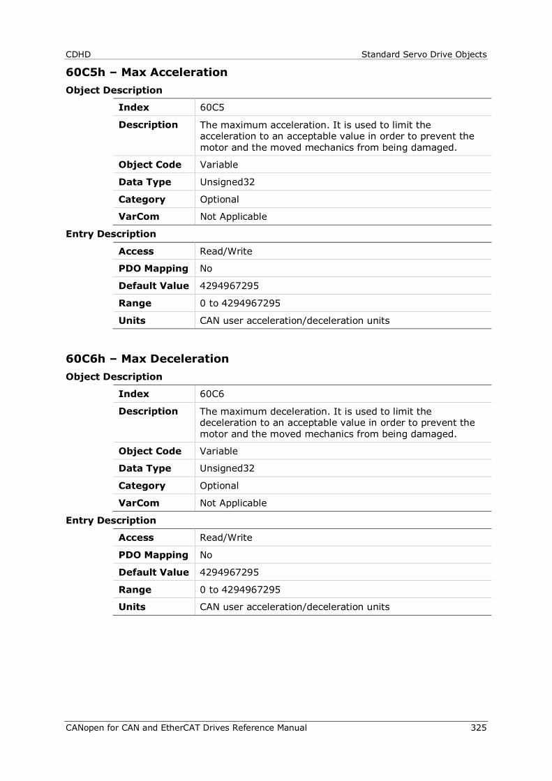
CDHD Standard Servo Drive Objects
CANopen for CAN and EtherCAT Drives Reference Manual 325
60C5h – Max Acceleration Object Description
Index 60C5
Description The maximum acceleration. It is used to limit the acceleration to an acceptable value in order to prevent the motor and the moved mechanics from being damaged.
Object Code Variable
Data Type Unsigned32
Category Optional
VarCom Not Applicable
Entry Description
Access Read/Write
PDO Mapping No
Default Value 4294967295
Range 0 to 4294967295
Units CAN user acceleration/deceleration units
60C6h – Max Deceleration Object Description
Index 60C6
Description The maximum deceleration. It is used to limit the deceleration to an acceptable value in order to prevent the motor and the moved mechanics from being damaged.
Object Code Variable
Data Type Unsigned32
Category Optional
VarCom Not Applicable
Entry Description
Access Read/Write
PDO Mapping No
Default Value 4294967295
Range 0 to 4294967295
Units CAN user acceleration/deceleration units
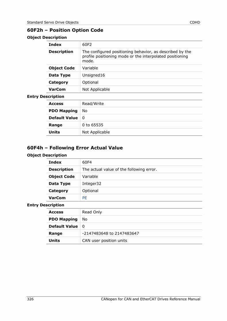
Standard Servo Drive Objects CDHD
326 CANopen for CAN and EtherCAT Drives Reference Manual
60F2h – Position Option Code Object Description
Index 60F2
Description The configured positioning behavior, as described by the profile positioning mode or the interpolated positioning mode.
Object Code Variable
Data Type Unsigned16
Category Optional
VarCom Not Applicable
Entry Description
Access Read/Write
PDO Mapping No
Default Value 0
Range 0 to 65535
Units Not Applicable
60F4h – Following Error Actual Value Object Description
Index 60F4
Description The actual value of the following error.
Object Code Variable
Data Type Integer32
Category Optional
VarCom PE
Entry Description
Access Read Only
PDO Mapping No
Default Value 0
Range -2147483648 to 2147483647
Units CAN user position units
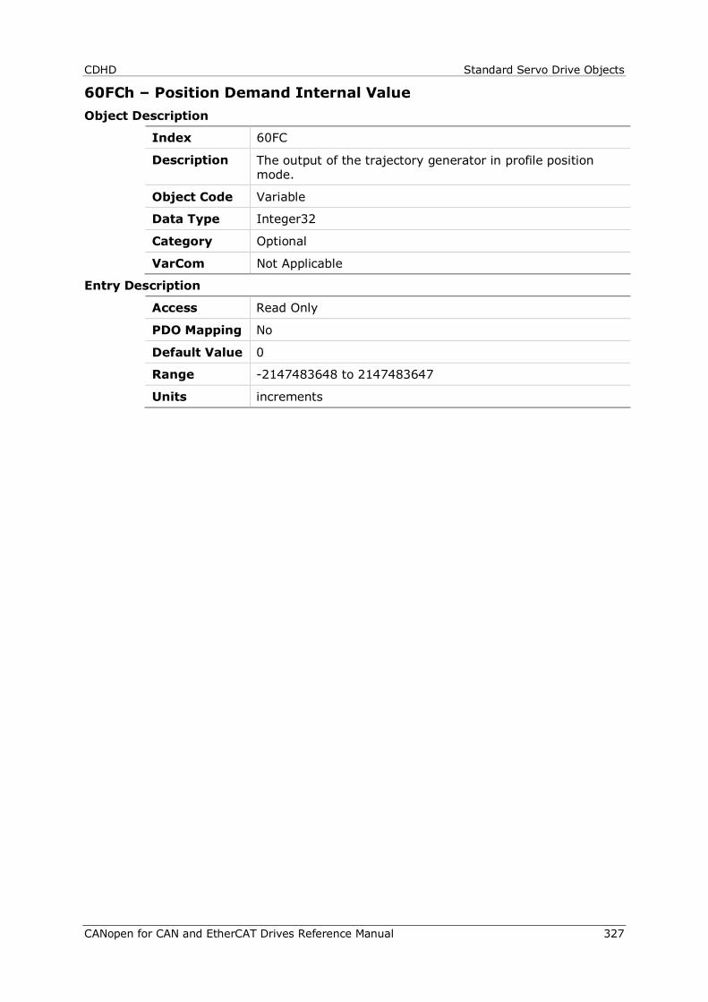
CDHD Standard Servo Drive Objects
CANopen for CAN and EtherCAT Drives Reference Manual 327
60FCh – Position Demand Internal Value Object Description
Index 60FC
Description The output of the trajectory generator in profile position mode.
Object Code Variable
Data Type Integer32
Category Optional
VarCom Not Applicable
Entry Description
Access Read Only
PDO Mapping No
Default Value 0
Range -2147483648 to 2147483647
Units increments
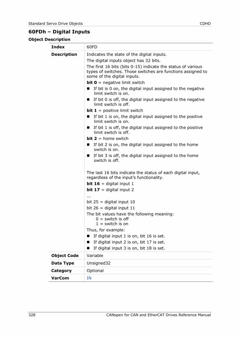
Standard Servo Drive Objects CDHD
328 CANopen for CAN and EtherCAT Drives Reference Manual
60FDh – Digital Inputs Object Description
Index 60FD
Description Indicates the state of the digital inputs. The digital inputs object has 32 bits. The first 16 bits (bits 0-15) indicate the status of various types of switches. Those switches are functions assigned to some of the digital inputs. bit 0 = negative limit switch If bit is 0 on, the digital input assigned to the negative
limit switch is on. If bit 0 is off, the digital input assigned to the negative
limit switch is off. bit 1 = positive limit switch If bit 1 is on, the digital input assigned to the positive
limit switch is on. If bit 1 is off, the digital input assigned to the positive
limit switch is off. bit 2 = home switch If bit 2 is on, the digital input assigned to the home
switch is on. If bit 3 is off, the digital input assigned to the home
switch is off. The last 16 bits indicate the status of each digital input, regardless of the input’s functionality. bit 16 = digital input 1 bit 17 = digital input 2 ... bit 25 = digital input 10 bit 26 = digital input 11 The bit values have the following meaning:
0 = switch is off 1 = switch is on
Thus, for example: If digital input 1 is on, bit 16 is set. If digital input 2 is on, bit 17 is set. If digital input 3 is on, bit 18 is set.
Object Code Variable
Data Type Unsigned32
Category Optional
VarCom IN
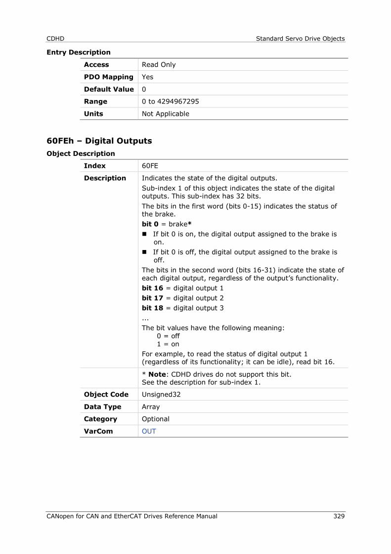
CDHD Standard Servo Drive Objects
CANopen for CAN and EtherCAT Drives Reference Manual 329
Entry Description
Access Read Only
PDO Mapping Yes
Default Value 0
Range 0 to 4294967295
Units Not Applicable
60FEh – Digital Outputs Object Description
Index 60FE
Description Indicates the state of the digital outputs. Sub-index 1 of this object indicates the state of the digital outputs. This sub-index has 32 bits. The bits in the first word (bits 0-15) indicates the status of the brake. bit 0 = brake* If bit 0 is on, the digital output assigned to the brake is
on. If bit 0 is off, the digital output assigned to the brake is
off. The bits in the second word (bits 16-31) indicate the state of each digital output, regardless of the output’s functionality. bit 16 = digital output 1 bit 17 = digital output 2 bit 18 = digital output 3 ... The bit values have the following meaning:
0 = off 1 = on
For example, to read the status of digital output 1 (regardless of its functionality; it can be idle), read bit 16.
* Note: CDHD drives do not support this bit. See the description for sub-index 1.
Object Code Unsigned32
Data Type Array
Category Optional
VarCom OUT
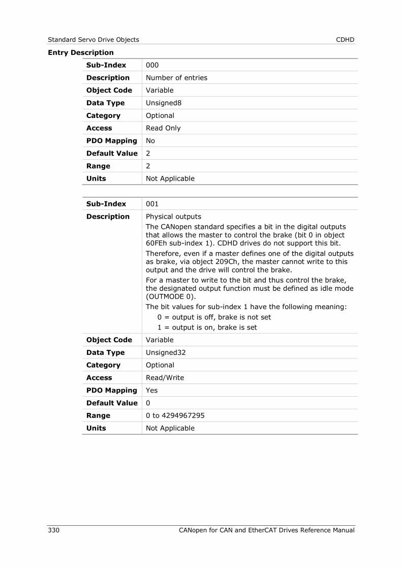
Standard Servo Drive Objects CDHD
330 CANopen for CAN and EtherCAT Drives Reference Manual
Entry Description
Sub-Index 000
Description Number of entries
Object Code Variable
Data Type Unsigned8
Category Optional
Access Read Only
PDO Mapping No
Default Value 2
Range 2
Units Not Applicable
Sub-Index 001
Description Physical outputs The CANopen standard specifies a bit in the digital outputs that allows the master to control the brake (bit 0 in object 60FEh sub-index 1). CDHD drives do not support this bit. Therefore, even if a master defines one of the digital outputs as brake, via object 209Ch, the master cannot write to this output and the drive will control the brake. For a master to write to the bit and thus control the brake, the designated output function must be defined as idle mode (OUTMODE 0). The bit values for sub-index 1 have the following meaning: 0 = output is off, brake is not set 1 = output is on, brake is set
Object Code Variable
Data Type Unsigned32
Category Optional
Access Read/Write
PDO Mapping Yes
Default Value 0
Range 0 to 4294967295
Units Not Applicable
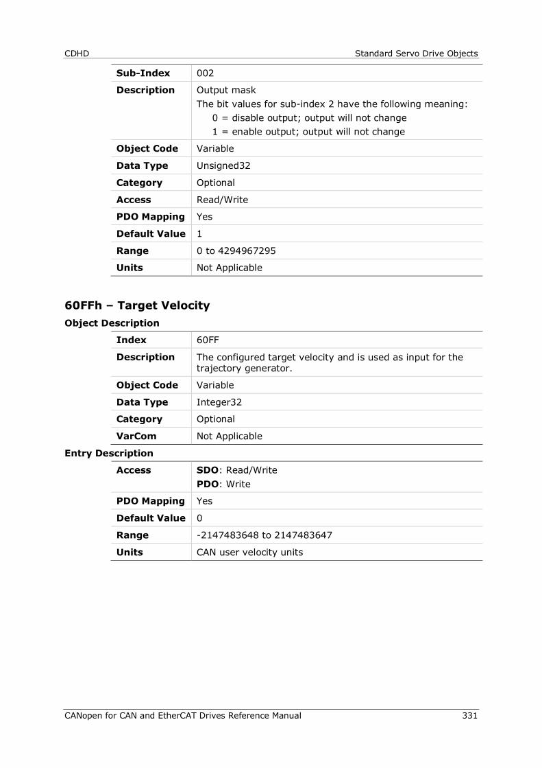
CDHD Standard Servo Drive Objects
CANopen for CAN and EtherCAT Drives Reference Manual 331
Sub-Index 002
Description Output mask The bit values for sub-index 2 have the following meaning: 0 = disable output; output will not change 1 = enable output; output will not change
Object Code Variable
Data Type Unsigned32
Category Optional
Access Read/Write
PDO Mapping Yes
Default Value 1
Range 0 to 4294967295
Units Not Applicable
60FFh – Target Velocity Object Description
Index 60FF
Description The configured target velocity and is used as input for the trajectory generator.
Object Code Variable
Data Type Integer32
Category Optional
VarCom Not Applicable
Entry Description
Access SDO: Read/Write PDO: Write
PDO Mapping Yes
Default Value 0
Range -2147483648 to 2147483647
Units CAN user velocity units
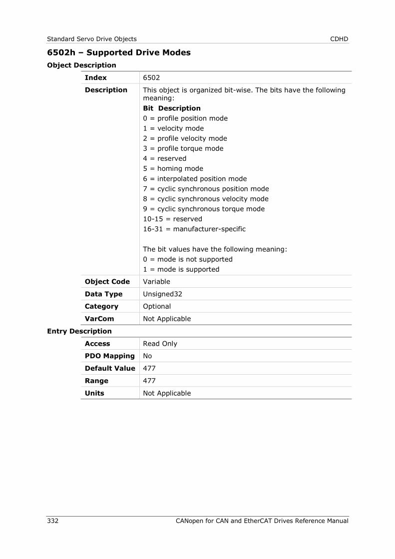
Standard Servo Drive Objects CDHD
332 CANopen for CAN and EtherCAT Drives Reference Manual
6502h – Supported Drive Modes Object Description
Index 6502
Description This object is organized bit-wise. The bits have the following meaning: Bit Description 0 = profile position mode 1 = velocity mode 2 = profile velocity mode 3 = profile torque mode 4 = reserved 5 = homing mode 6 = interpolated position mode 7 = cyclic synchronous position mode 8 = cyclic synchronous velocity mode 9 = cyclic synchronous torque mode 10-15 = reserved 16-31 = manufacturer-specific The bit values have the following meaning: 0 = mode is not supported 1 = mode is supported
Object Code Variable
Data Type Unsigned32
Category Optional
VarCom Not Applicable
Entry Description
Access Read Only
PDO Mapping No
Default Value 477
Range 477
Units Not Applicable
CDHD Standard Servo Drive Objects
CANopen for CAN and EtherCAT Drives Reference Manual 333

CAN Operation CDHD
334 CANopen for CAN and EtherCAT Drives Reference Manual
7 CAN Operation
7.1 Device Control and State Machine
The power drive system finite-state automaton (PDS FSA) is a mathematical model that defines the behavior of the power drive system. Because a power drive system is required to provide local control even when the communication network is not functioning properly, the communication FSA and the PDS FSA are only loosely coupled. Figure shows how the power drive system operates remotely via the network, or locally.
Figure 7-1. Remote and Local Control
The power drive system is operated by the Controlword sent by the control device via the network. The state of the power drive system is reported by the Statusword produced by the drive device. The FSA is also controlled by error detection signals.
The PDS FSA defines the power drive system status and the possible control sequence of the power drive system. A single state represents a special internal or external behavior. The state of the power drive system also determines which commands are accepted. For example, it is only possible to start a point-to-point move when the drive is in the operation enabled state.
7.2 Indicating the Operating State
After switching on, and when an operating mode is started, the power drive system goes through a number of operating states. The operating states are internally monitored and influenced by monitoring functions
Figure 7-2illustrates the PDS FSA behavior. It takes into consideration the control of the power electronics, in accordance with user commands and internal drive faults.
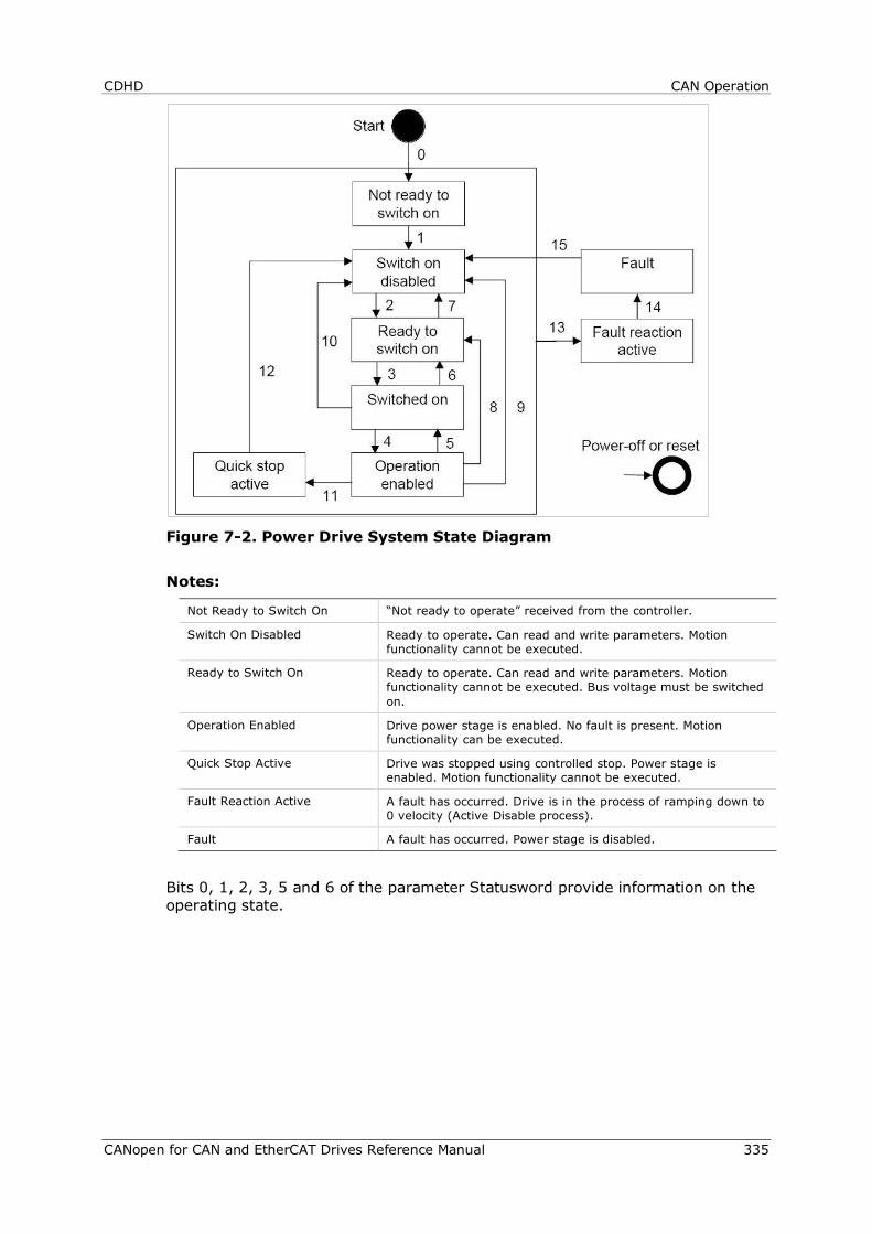
CDHD CAN Operation
CANopen for CAN and EtherCAT Drives Reference Manual 335
Figure 7-2. Power Drive System State Diagram
Notes:
Not Ready to Switch On “Not ready to operate” received from the controller.
Switch On Disabled Ready to operate. Can read and write parameters. Motion functionality cannot be executed.
Ready to Switch On Ready to operate. Can read and write parameters. Motion functionality cannot be executed. Bus voltage must be switched on.
Operation Enabled Drive power stage is enabled. No fault is present. Motion functionality can be executed.
Quick Stop Active Drive was stopped using controlled stop. Power stage is enabled. Motion functionality cannot be executed.
Fault Reaction Active A fault has occurred. Drive is in the process of ramping down to 0 velocity (Active Disable process).
Fault A fault has occurred. Power stage is disabled.
Bits 0, 1, 2, 3, 5 and 6 of the parameter Statusword provide information on the operating state.
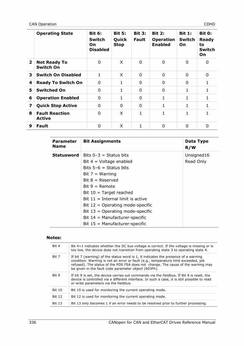
CAN Operation CDHD
336 CANopen for CAN and EtherCAT Drives Reference Manual
Operating State Bit 6: Switch On Disabled
Bit 5: Quick Stop
Bit 3: Fault
Bit 2: Operation Enabled
Bit 1: Switch On
Bit 0: Ready to Switch On
2 Not Ready To Switch On
0 X 0 0 0 0
3 Switch On Disabled 1 X 0 0 0 0
4 Ready To Switch On 0 1 0 0 0 1
5 Switched On 0 1 0 0 1 1
6 Operation Enabled 0 1 0 1 1 1
7 Quick Stop Active 0 0 0 1 1 1
8 Fault Reaction Active
0 X 1 1 1 1
9 Fault 0 X 1 0 0 0
Parameter Name
Bit Assignments Data Type R/W
Statusword Bits 0–3 = Status bits Bit 4 = Voltage enabled Bits 5–6 = Status bits Bit 7 = Warning Bit 8 = Reserved Bit 9 = Remote Bit 10 = Target reached Bit 11 = Internal limit is active Bit 12 = Operating mode-specific Bit 13 = Operating mode-specific Bit 14 = Manufacturer-specific Bit 15 = Manufacturer-specific
Unsigned16 Read Only
Notes:
Bit 4 Bit 4=1 indicates whether the DC bus voltage is correct. If the voltage is missing or is too low, the device does not transition from operating state 3 to operating state 4.
Bit 7 If bit 7 (warning) of the status word is 1, it indicates the presence of a warning condition. Warning is not an error or fault (e.g., temperature limit exceeded, job refused). The status of the PDS FSA does not change. The cause of the warning may be given in the fault code parameter object (603Fh).
Bit 9 If bit 9 is set, the device carries out commands via the fieldbus. If Bit 9 is reset, the device is controlled via a different interface. In such a case, it is still possible to read or write parameters via the fieldbus.
Bit 10 Bit 10 is used for monitoring the current operating mode.
Bit 12 Bit 12 is used for monitoring the current operating mode.
Bit 13 Bit 13 only becomes 1 if an error needs to be resolved prior to further processing.
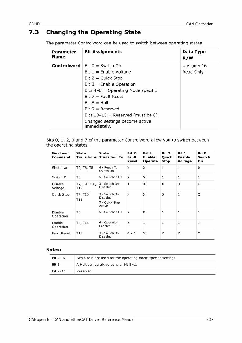
CDHD CAN Operation
CANopen for CAN and EtherCAT Drives Reference Manual 337
7.3 Changing the Operating State
The parameter Controlword can be used to switch between operating states.
Parameter Name
Bit Assignments Data Type R/W
Controlword Bit 0 = Switch On Bit 1 = Enable Voltage Bit 2 = Quick Stop Bit 3 = Enable Operation Bits 4–6 = Operating Mode specific Bit 7 = Fault Reset Bit 8 = Halt Bit 9 = Reserved Bits 10–15 = Reserved (must be 0) Changed settings become active immediately.
Unsigned16 Read Only
Bits 0, 1, 2, 3 and 7 of the parameter Controlword allow you to switch between the operating states.
Fieldbus Command
State Transitions
State Transition To
Bit 7: Fault Reset
Bit 3: Enable Operate
Bit 2: Quick Stop
Bit 1: Enable Voltage
Bit 0: Switch On
Shutdown T2, T6, T8 4 - Ready To Switch On
X X 1 1 0
Switch On T3 5 - Switched On X X 1 1 1
Disable Voltage
T7, T9, T10, T12
3 - Switch On Disabled
X X X 0 X
Quick Stop T7, T10 T11
3 - Switch On Disabled 7 - Quick Stop Active
X X 0 1 X
Disable Operation
T5 5 - Switched On X 0 1 1 1
Enable Operation
T4, T16 6 - Operation Enabled
X 1 1 1 1
Fault Reset T15 3 - Switch On Disabled
0 » 1 X X X X
Notes:
Bit 4—6 Bits 4 to 6 are used for the operating mode-specific settings.
Bit 8 A Halt can be triggered with bit 8=1.
Bit 9–15 Reserved.
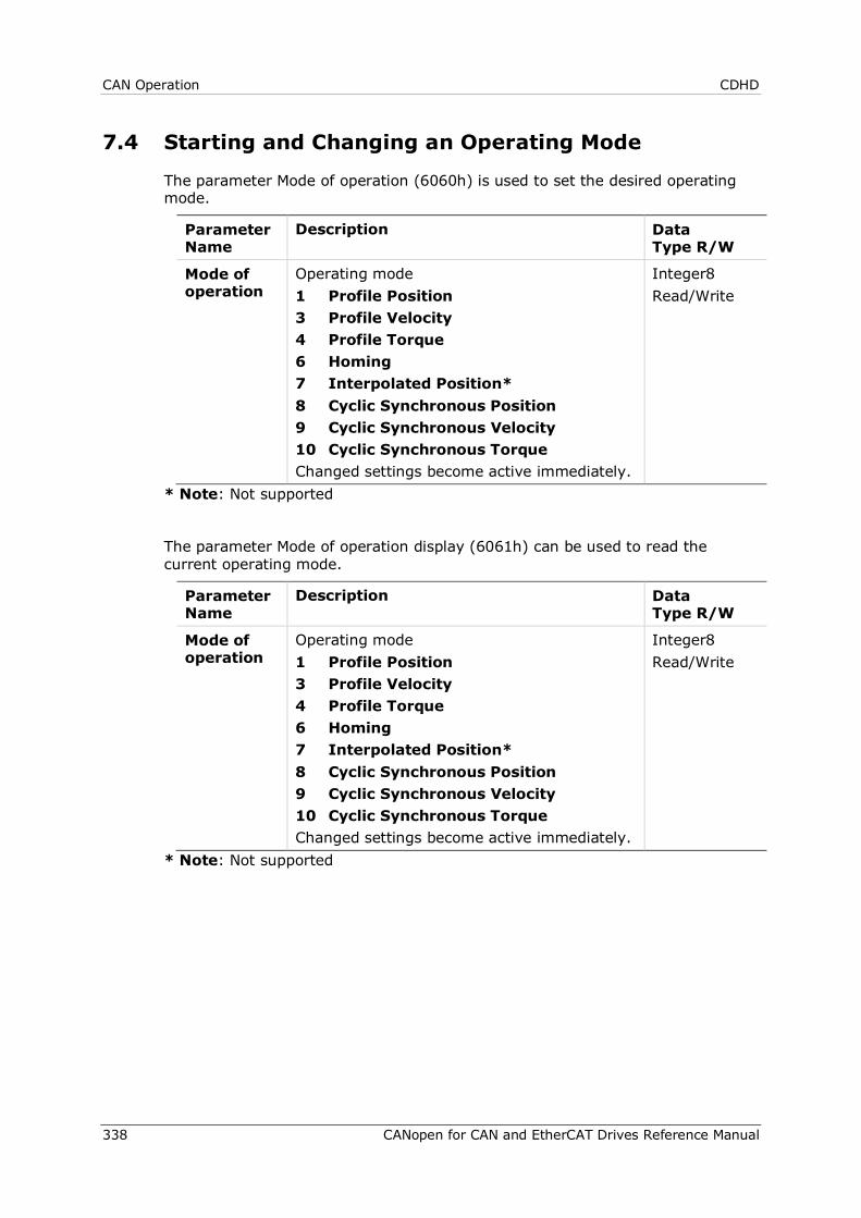
CAN Operation CDHD
338 CANopen for CAN and EtherCAT Drives Reference Manual
7.4 Starting and Changing an Operating Mode
The parameter Mode of operation (6060h) is used to set the desired operating mode.
Parameter Name
Description Data Type R/W
Mode of operation
Operating mode 1 Profile Position 3 Profile Velocity 4 Profile Torque 6 Homing 7 Interpolated Position* 8 Cyclic Synchronous Position 9 Cyclic Synchronous Velocity 10 Cyclic Synchronous Torque Changed settings become active immediately.
Integer8 Read/Write
* Note: Not supported
The parameter Mode of operation display (6061h) can be used to read the current operating mode.
Parameter Name
Description Data Type R/W
Mode of operation
Operating mode 1 Profile Position 3 Profile Velocity 4 Profile Torque 6 Homing 7 Interpolated Position* 8 Cyclic Synchronous Position 9 Cyclic Synchronous Velocity 10 Cyclic Synchronous Torque Changed settings become active immediately.
Integer8 Read/Write
* Note: Not supported
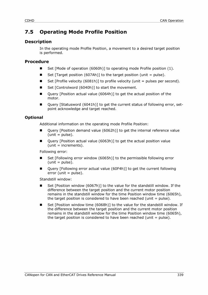
CDHD CAN Operation
CANopen for CAN and EtherCAT Drives Reference Manual 339
7.5 Operating Mode Profile Position
Description In the operating mode Profile Position, a movement to a desired target position is performed.
Procedure Set [Mode of operation (6060h)] to operating mode Profile position (1).
Set [Target position (607Ah)] to the target position (unit = pulse).
Set [Profile velocity (6081h)] to profile velocity (unit = pulses per second).
Set [Controlword (6040h)] to start the movement.
Query [Position actual value (6064h)] to get the actual position of the motor.
Query [Statusword (6041h)] to get the current status of following error, set-point acknowledge and target reached.
Optional Additional information on the operating mode Profile Position:
Query [Position demand value (6062h)] to get the internal reference value (unit = pulse).
Query [Position actual value (6063h)] to get the actual position value (unit = increments).
Following error:
Set [Following error window (6065h)] to the permissible following error (unit = pulse).
Query [Following error actual value (60F4h)] to get the current following error (unit = pulse).
Standstill window:
Set [Position window (6067h)] to the value for the standstill window. If the difference between the target position and the current motor position remains in the standstill window for the time Position window time (6065h), the target position is considered to have been reached (unit = pulse).
Set [Position window time (6068h)] to the value for the standstill window. If the difference between the target position and the current motor position remains in the standstill window for the time Position window time (6065h), the target position is considered to have been reached (unit = pulse).
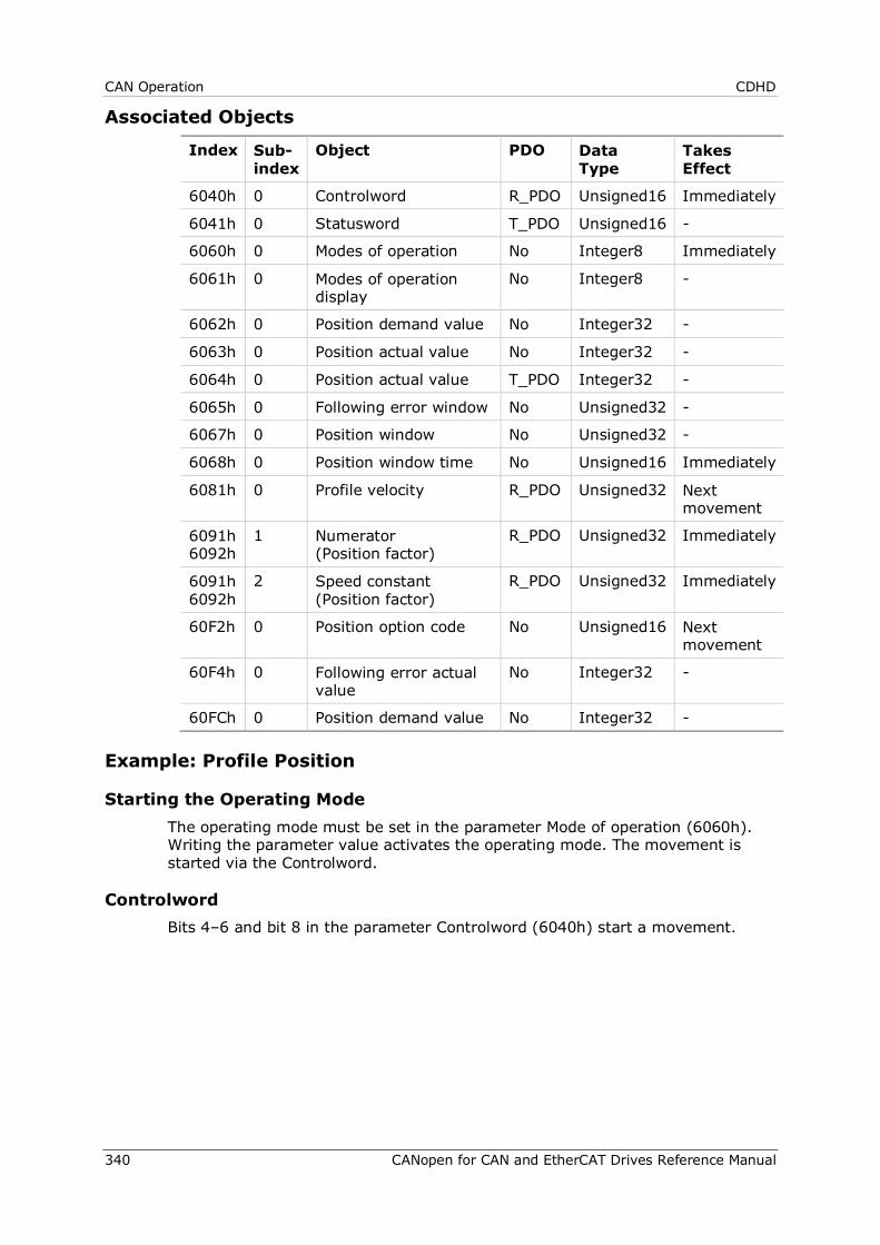
CAN Operation CDHD
340 CANopen for CAN and EtherCAT Drives Reference Manual
Associated Objects
Index Sub-index
Object PDO Data Type
Takes Effect
6040h 0 Controlword R_PDO Unsigned16 Immediately
6041h 0 Statusword T_PDO Unsigned16 -
6060h 0 Modes of operation No Integer8 Immediately
6061h 0 Modes of operation display
No Integer8 -
6062h 0 Position demand value No Integer32 -
6063h 0 Position actual value No Integer32 -
6064h 0 Position actual value T_PDO Integer32 -
6065h 0 Following error window No Unsigned32 -
6067h 0 Position window No Unsigned32 -
6068h 0 Position window time No Unsigned16 Immediately
6081h 0 Profile velocity R_PDO Unsigned32 Next movement
6091h 6092h
1 Numerator (Position factor)
R_PDO Unsigned32 Immediately
6091h 6092h
2 Speed constant (Position factor)
R_PDO Unsigned32 Immediately
60F2h 0 Position option code No Unsigned16 Next movement
60F4h 0 Following error actual value
No Integer32 -
60FCh 0 Position demand value No Integer32 -
Example: Profile Position
Starting the Operating Mode The operating mode must be set in the parameter Mode of operation (6060h). Writing the parameter value activates the operating mode. The movement is started via the Controlword.
Controlword Bits 4–6 and bit 8 in the parameter Controlword (6040h) start a movement.
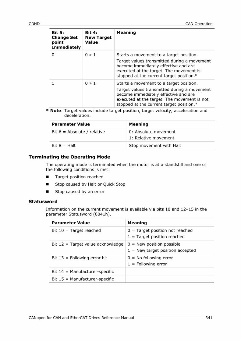
CDHD CAN Operation
CANopen for CAN and EtherCAT Drives Reference Manual 341
Bit 5: Change Set point Immediately
Bit 4: New Target Value
Meaning
0 0 » 1 Starts a movement to a target position. Target values transmitted during a movement become immediately effective and are executed at the target. The movement is stopped at the current target position.*
1 0 » 1 Starts a movement to a target position. Target values transmitted during a movement become immediately effective and are executed at the target. The movement is not stopped at the current target position.*
* Note: Target values include target position, target velocity, acceleration and deceleration.
Parameter Value Meaning
Bit 6 = Absolute / relative 0: Absolute movement 1: Relative movement
Bit 8 = Halt Stop movement with Halt
Terminating the Operating Mode The operating mode is terminated when the motor is at a standstill and one of the following conditions is met:
Target position reached
Stop caused by Halt or Quick Stop
Stop caused by an error
Statusword Information on the current movement is available via bits 10 and 12–15 in the parameter Statusword (6041h).
Parameter Value Meaning
Bit 10 = Target reached 0 = Target position not reached 1 = Target position reached
Bit 12 = Target value acknowledge 0 = New position possible 1 = New target position accepted
Bit 13 = Following error bit 0 = No following error 1 = Following error
Bit 14 = Manufacturer-specific
Bit 15 = Manufacturer-specific
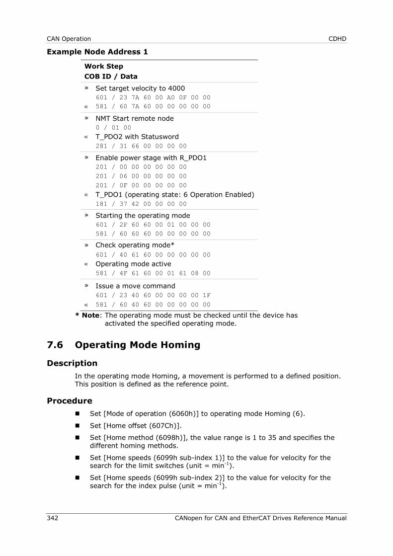
CAN Operation CDHD
342 CANopen for CAN and EtherCAT Drives Reference Manual
Example Node Address 1
Work Step COB ID / Data » Set target velocity to 4000 601 / 23 7A 60 00 A0 0F 00 00 « 581 / 60 7A 60 00 00 00 00 00 » NMT Start remote node 0 / 01 00 « T_PDO2 with Statusword 281 / 31 66 00 00 00 00 » Enable power stage with R_PDO1 201 / 00 00 00 00 00 00 201 / 06 00 00 00 00 00 201 / 0F 00 00 00 00 00 « T_PDO1 (operating state: 6 Operation Enabled) 181 / 37 42 00 00 00 00 » Starting the operating mode 601 / 2F 60 60 00 01 00 00 00 581 / 60 60 60 00 00 00 00 00 » Check operating mode* 601 / 40 61 60 00 00 00 00 00 « Operating mode active 581 / 4F 61 60 00 01 61 08 00 » Issue a move command 601 / 23 40 60 00 00 00 00 1F « 581 / 60 40 60 00 00 00 00 00
* Note: The operating mode must be checked until the device has activated the specified operating mode.
7.6 Operating Mode Homing
Description In the operating mode Homing, a movement is performed to a defined position. This position is defined as the reference point.
Procedure Set [Mode of operation (6060h)] to operating mode Homing (6).
Set [Home offset (607Ch)].
Set [Home method (6098h)], the value range is 1 to 35 and specifies the different homing methods.
Set [Home speeds (6099h sub-index 1)] to the value for velocity for the search for the limit switches (unit = min-1).
Set [Home speeds (6099h sub-index 2)] to the value for velocity for the search for the index pulse (unit = min-1).
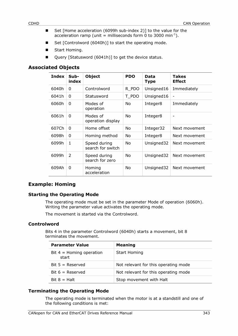
CDHD CAN Operation
CANopen for CAN and EtherCAT Drives Reference Manual 343
Set [Home acceleration (6099h sub-index 2)] to the value for the acceleration ramp (unit = milliseconds form 0 to 3000 min-1).
Set [Controlword (6040h)] to start the operating mode.
Start Homing.
Query [Statusword (6041h)] to get the device status.
Associated Objects
Index Sub-index
Object PDO Data Type
Takes Effect
6040h 0 Controlword R_PDO Unsigned16 Immediately
6041h 0 Statusword T_PDO Unsigned16 -
6060h 0 Modes of operation
No Integer8 Immediately
6061h 0 Modes of operation display
No Integer8 -
607Ch 0 Home offset No Integer32 Next movement
6098h 0 Homing method No Integer8 Next movement
6099h 1 Speed during search for switch
No Unsigned32 Next movement
6099h 2 Speed during search for zero
No Unsigned32 Next movement
609Ah 0 Homing acceleration
No Unsigned32 Next movement
Example: Homing
Starting the Operating Mode The operating mode must be set in the parameter Mode of operation (6060h). Writing the parameter value activates the operating mode.
The movement is started via the Controlword.
Controlword Bits 4 in the parameter Controlword (6040h) starts a movement, bit 8 terminates the movement.
Parameter Value Meaning
Bit 4 = Homing operation start
Start Homing
Bit 5 = Reserved Not relevant for this operating mode
Bit 6 = Reserved Not relevant for this operating mode
Bit 8 = Halt Stop movement with Halt
Terminating the Operating Mode The operating mode is terminated when the motor is at a standstill and one of the following conditions is met:
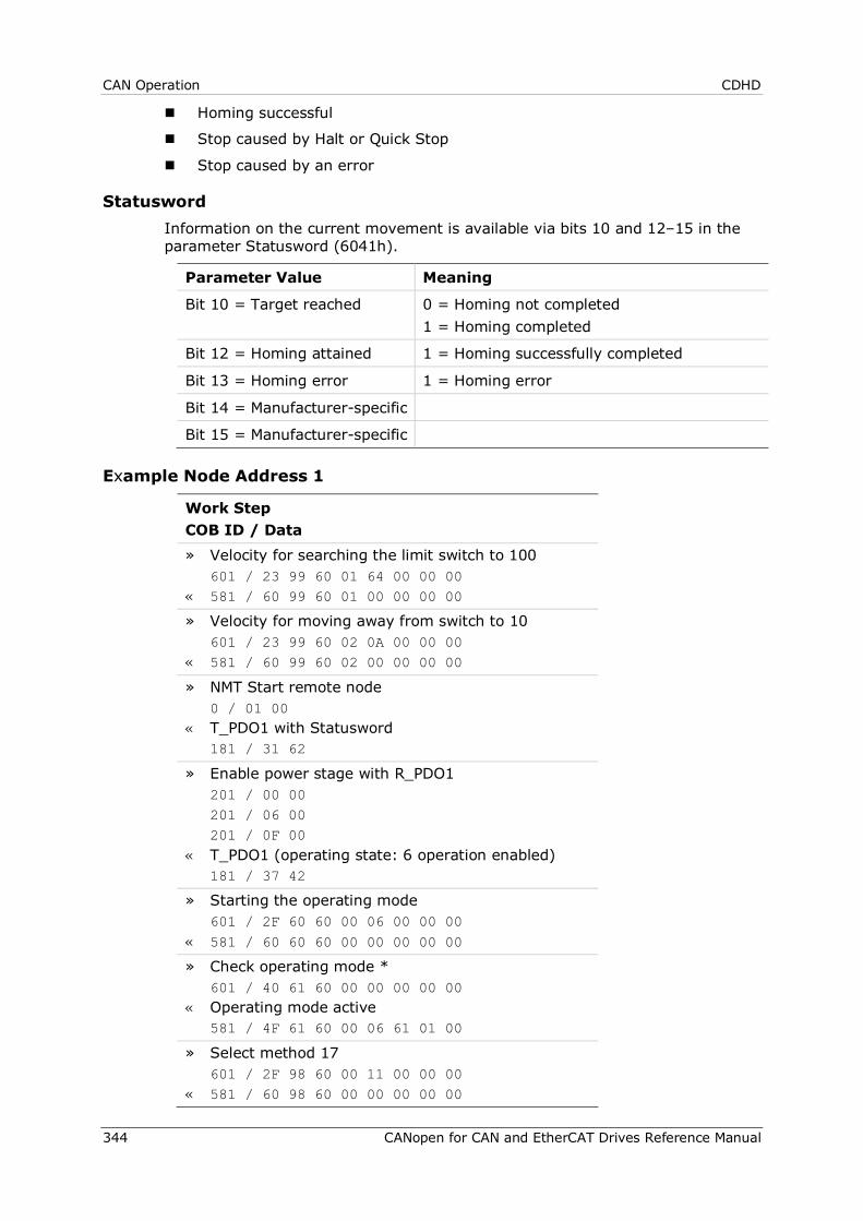
CAN Operation CDHD
344 CANopen for CAN and EtherCAT Drives Reference Manual
Homing successful
Stop caused by Halt or Quick Stop
Stop caused by an error
Statusword Information on the current movement is available via bits 10 and 12–15 in the parameter Statusword (6041h).
Parameter Value Meaning
Bit 10 = Target reached 0 = Homing not completed 1 = Homing completed
Bit 12 = Homing attained 1 = Homing successfully completed
Bit 13 = Homing error 1 = Homing error
Bit 14 = Manufacturer-specific
Bit 15 = Manufacturer-specific
Example Node Address 1
Work Step COB ID / Data » Velocity for searching the limit switch to 100 601 / 23 99 60 01 64 00 00 00 « 581 / 60 99 60 01 00 00 00 00
» Velocity for moving away from switch to 10 601 / 23 99 60 02 0A 00 00 00 « 581 / 60 99 60 02 00 00 00 00
» NMT Start remote node 0 / 01 00 « T_PDO1 with Statusword 181 / 31 62
» Enable power stage with R_PDO1 201 / 00 00 201 / 06 00 201 / 0F 00 « T_PDO1 (operating state: 6 operation enabled) 181 / 37 42
» Starting the operating mode 601 / 2F 60 60 00 06 00 00 00 « 581 / 60 60 60 00 00 00 00 00
» Check operating mode * 601 / 40 61 60 00 00 00 00 00 « Operating mode active 581 / 4F 61 60 00 06 61 01 00
» Select method 17 601 / 2F 98 60 00 11 00 00 00 « 581 / 60 98 60 00 00 00 00 00
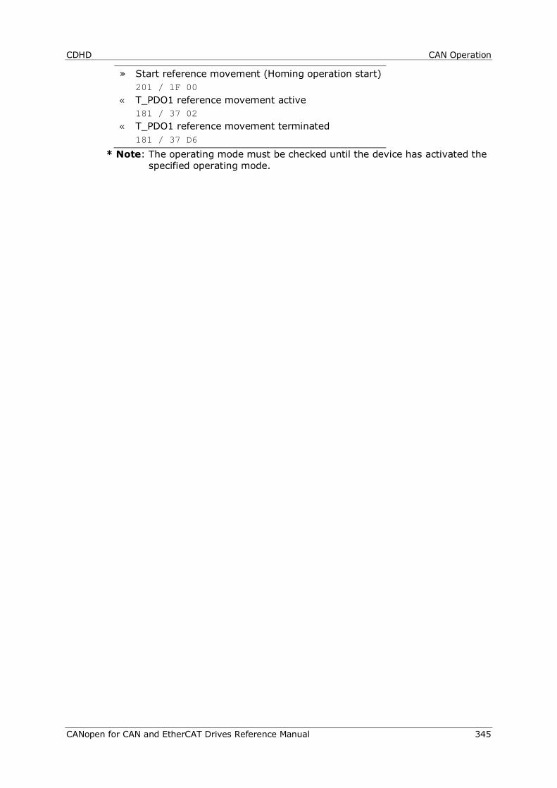
CDHD CAN Operation
CANopen for CAN and EtherCAT Drives Reference Manual 345
» Start reference movement (Homing operation start) 201 / 1F 00 « T_PDO1 reference movement active 181 / 37 02 « T_PDO1 reference movement terminated 181 / 37 D6
* Note: The operating mode must be checked until the device has activated the specified operating mode.
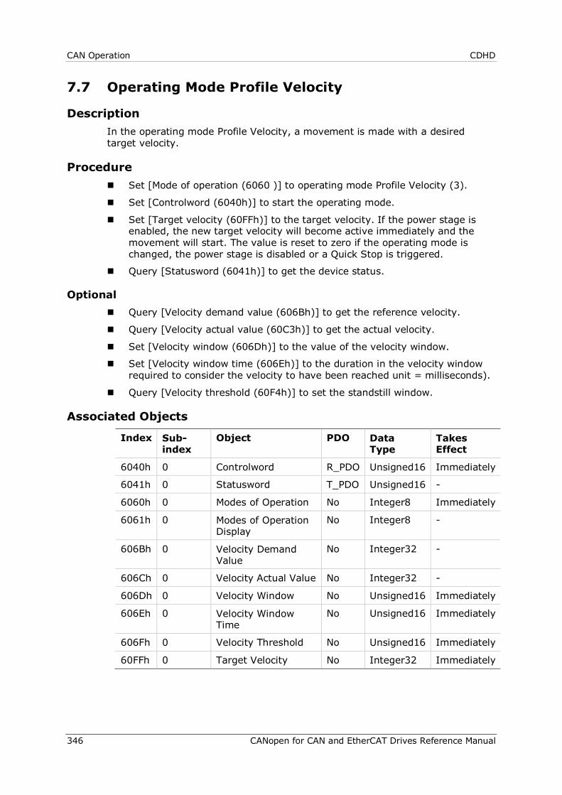
CAN Operation CDHD
346 CANopen for CAN and EtherCAT Drives Reference Manual
7.7 Operating Mode Profile Velocity
Description In the operating mode Profile Velocity, a movement is made with a desired target velocity.
Procedure Set [Mode of operation (6060 )] to operating mode Profile Velocity (3).
Set [Controlword (6040h)] to start the operating mode.
Set [Target velocity (60FFh)] to the target velocity. If the power stage is enabled, the new target velocity will become active immediately and the movement will start. The value is reset to zero if the operating mode is changed, the power stage is disabled or a Quick Stop is triggered.
Query [Statusword (6041h)] to get the device status.
Optional Query [Velocity demand value (606Bh)] to get the reference velocity.
Query [Velocity actual value (60C3h)] to get the actual velocity.
Set [Velocity window (606Dh)] to the value of the velocity window.
Set [Velocity window time (606Eh)] to the duration in the velocity window required to consider the velocity to have been reached unit = milliseconds).
Query [Velocity threshold (60F4h)] to set the standstill window.
Associated Objects
Index Sub-index
Object PDO Data Type
Takes Effect
6040h 0 Controlword R_PDO Unsigned16 Immediately
6041h 0 Statusword T_PDO Unsigned16 -
6060h 0 Modes of Operation No Integer8 Immediately
6061h 0 Modes of Operation Display
No Integer8 -
606Bh 0 Velocity Demand Value
No Integer32 -
606Ch 0 Velocity Actual Value No Integer32 -
606Dh 0 Velocity Window No Unsigned16 Immediately
606Eh 0 Velocity Window Time
No Unsigned16 Immediately
606Fh 0 Velocity Threshold No Unsigned16 Immediately
60FFh 0 Target Velocity No Integer32 Immediately
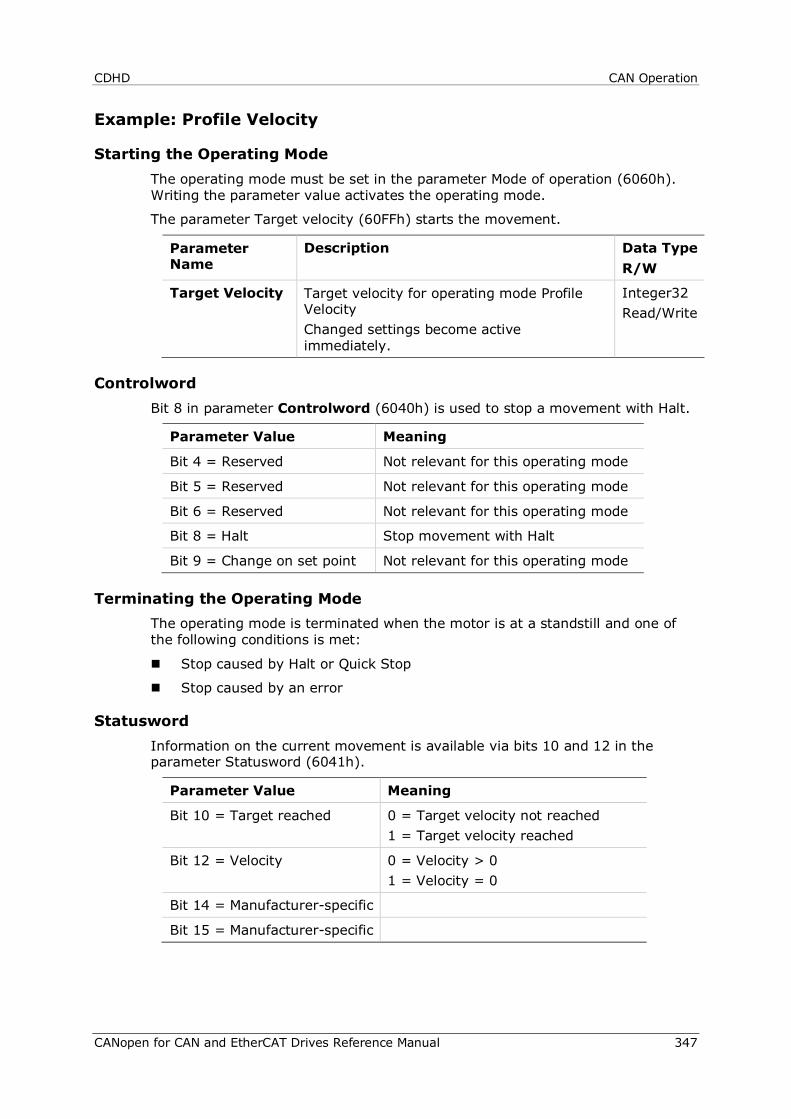
CDHD CAN Operation
CANopen for CAN and EtherCAT Drives Reference Manual 347
Example: Profile Velocity
Starting the Operating Mode The operating mode must be set in the parameter Mode of operation (6060h). Writing the parameter value activates the operating mode.
The parameter Target velocity (60FFh) starts the movement.
Parameter Name
Description Data Type R/W
Target Velocity Target velocity for operating mode Profile Velocity Changed settings become active immediately.
Integer32 Read/Write
Controlword Bit 8 in parameter Controlword (6040h) is used to stop a movement with Halt.
Parameter Value Meaning
Bit 4 = Reserved Not relevant for this operating mode
Bit 5 = Reserved Not relevant for this operating mode
Bit 6 = Reserved Not relevant for this operating mode
Bit 8 = Halt Stop movement with Halt
Bit 9 = Change on set point Not relevant for this operating mode
Terminating the Operating Mode The operating mode is terminated when the motor is at a standstill and one of the following conditions is met:
Stop caused by Halt or Quick Stop
Stop caused by an error
Statusword Information on the current movement is available via bits 10 and 12 in the parameter Statusword (6041h).
Parameter Value Meaning
Bit 10 = Target reached 0 = Target velocity not reached 1 = Target velocity reached
Bit 12 = Velocity 0 = Velocity > 0 1 = Velocity = 0
Bit 14 = Manufacturer-specific
Bit 15 = Manufacturer-specific
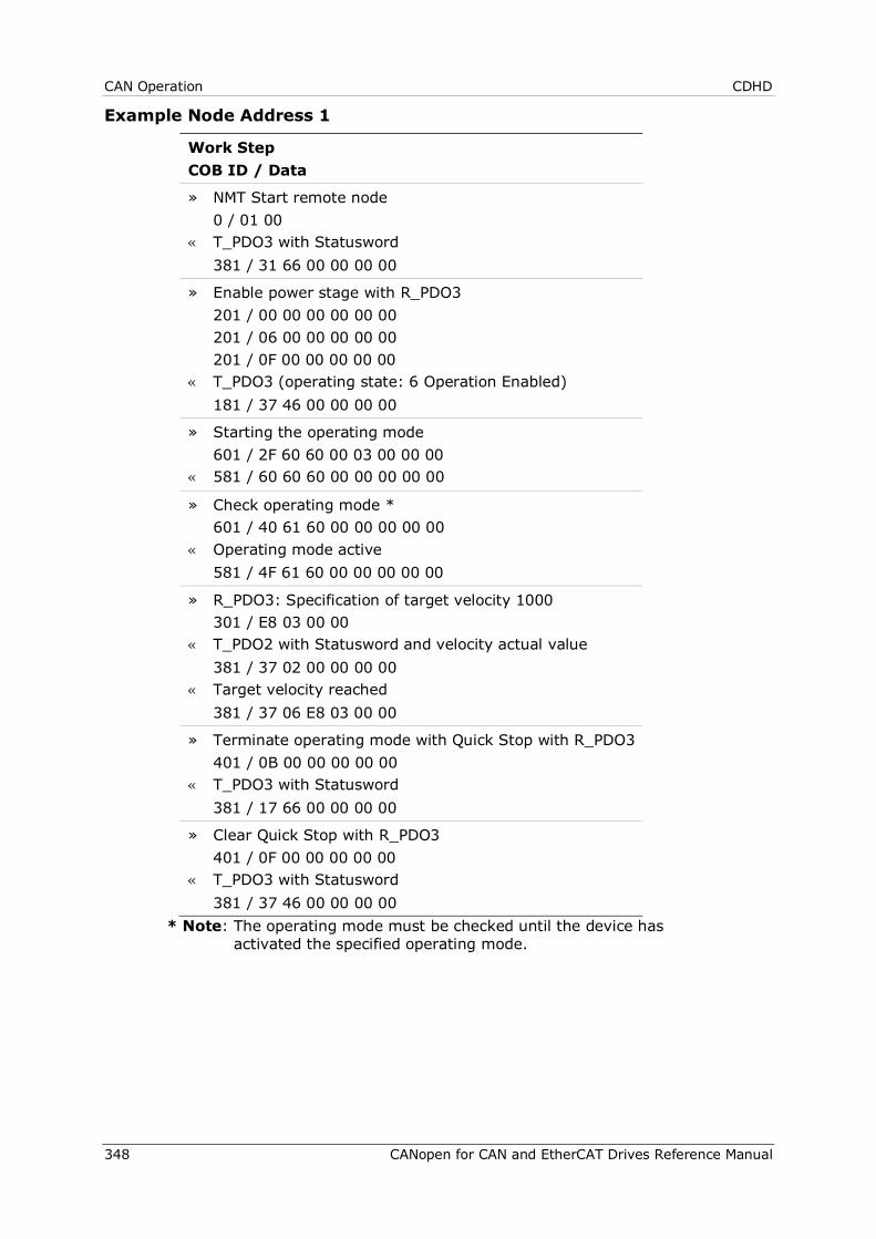
CAN Operation CDHD
348 CANopen for CAN and EtherCAT Drives Reference Manual
Example Node Address 1
Work Step COB ID / Data
» NMT Start remote node 0 / 01 00 « T_PDO3 with Statusword 381 / 31 66 00 00 00 00
» Enable power stage with R_PDO3 201 / 00 00 00 00 00 00 201 / 06 00 00 00 00 00 201 / 0F 00 00 00 00 00 « T_PDO3 (operating state: 6 Operation Enabled) 181 / 37 46 00 00 00 00
» Starting the operating mode 601 / 2F 60 60 00 03 00 00 00 « 581 / 60 60 60 00 00 00 00 00
» Check operating mode * 601 / 40 61 60 00 00 00 00 00 « Operating mode active 581 / 4F 61 60 00 00 00 00 00
» R_PDO3: Specification of target velocity 1000 301 / E8 03 00 00 « T_PDO2 with Statusword and velocity actual value 381 / 37 02 00 00 00 00 « Target velocity reached 381 / 37 06 E8 03 00 00
» Terminate operating mode with Quick Stop with R_PDO3 401 / 0B 00 00 00 00 00 « T_PDO3 with Statusword 381 / 17 66 00 00 00 00
» Clear Quick Stop with R_PDO3 401 / 0F 00 00 00 00 00 « T_PDO3 with Statusword 381 / 37 46 00 00 00 00
* Note: The operating mode must be checked until the device has activated the specified operating mode.
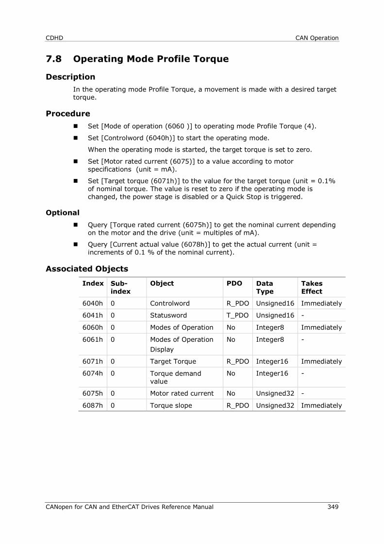
CDHD CAN Operation
CANopen for CAN and EtherCAT Drives Reference Manual 349
7.8 Operating Mode Profile Torque
Description In the operating mode Profile Torque, a movement is made with a desired target torque.
Procedure Set [Mode of operation (6060 )] to operating mode Profile Torque (4).
Set [Controlword (6040h)] to start the operating mode.
When the operating mode is started, the target torque is set to zero.
Set [Motor rated current (6075)] to a value according to motor specifications (unit = mA).
Set [Target torque (6071h)] to the value for the target torque (unit = 0.1% of nominal torque. The value is reset to zero if the operating mode is changed, the power stage is disabled or a Quick Stop is triggered.
Optional Query [Torque rated current (6075h)] to get the nominal current depending
on the motor and the drive (unit = multiples of mA).
Query [Current actual value (6078h)] to get the actual current (unit = increments of 0.1 % of the nominal current).
Associated Objects
Index Sub-index
Object PDO Data Type
Takes Effect
6040h 0 Controlword R_PDO Unsigned16 Immediately
6041h 0 Statusword T_PDO Unsigned16 -
6060h 0 Modes of Operation No Integer8 Immediately
6061h 0 Modes of Operation Display
No Integer8 -
6071h 0 Target Torque R_PDO Integer16 Immediately
6074h 0 Torque demand value
No Integer16 -
6075h 0 Motor rated current No Unsigned32 -
6087h 0 Torque slope R_PDO Unsigned32 Immediately
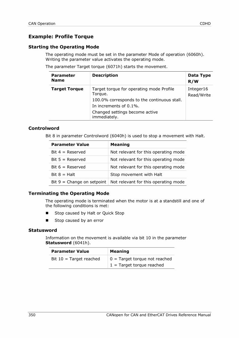
CAN Operation CDHD
350 CANopen for CAN and EtherCAT Drives Reference Manual
Example: Profile Torque
Starting the Operating Mode The operating mode must be set in the parameter Mode of operation (6060h). Writing the parameter value activates the operating mode.
The parameter Target torque (6071h) starts the movement.
Parameter Name
Description Data Type R/W
Target Torque Target torque for operating mode Profile Torque. 100.0% corresponds to the continuous stall. In increments of 0.1%. Changed settings become active immediately.
Integer16 Read/Write
Controlword Bit 8 in parameter Controlword (6040h) is used to stop a movement with Halt.
Parameter Value Meaning
Bit 4 = Reserved Not relevant for this operating mode
Bit 5 = Reserved Not relevant for this operating mode
Bit 6 = Reserved Not relevant for this operating mode
Bit 8 = Halt Stop movement with Halt
Bit 9 = Change on setpoint Not relevant for this operating mode
Terminating the Operating Mode The operating mode is terminated when the motor is at a standstill and one of the following conditions is met:
Stop caused by Halt or Quick Stop
Stop caused by an error
Statusword Information on the movement is available via bit 10 in the parameter Statusword (6041h).
Parameter Value Meaning
Bit 10 = Target reached 0 = Target torque not reached 1 = Target torque reached
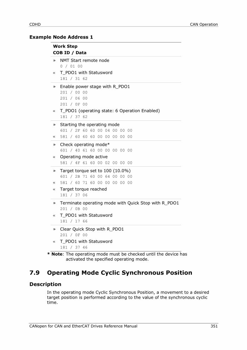
CDHD CAN Operation
CANopen for CAN and EtherCAT Drives Reference Manual 351
Example Node Address 1
Work Step COB ID / Data
» NMT Start remote node 0 / 01 00
« T_PDO1 with Statusword 181 / 31 62
» Enable power stage with R_PDO1 201 / 00 00 201 / 06 00
201 / 0F 00
« T_PDO1 (operating state: 6 Operation Enabled) 181 / 37 62
» Starting the operating mode 601 / 2F 60 60 00 04 00 00 00
« 581 / 60 60 60 00 00 00 00 00
» Check operating mode* 601 / 40 61 60 00 00 00 00 00
« Operating mode active 581 / 4F 61 60 00 02 00 00 00
» Target torque set to 100 (10.0%) 601 / 2B 71 60 00 64 00 00 00
« 581 / 60 71 60 00 00 00 00 00
« Target torque reached 181 / 37 06
» Terminate operating mode with Quick Stop with R_PDO1 201 / 0B 00
« T_PDO1 with Statusword 181 / 17 66
» Clear Quick Stop with R_PDO1 201 / 0F 00
« T_PDO1 with Statusword 181 / 37 46
* Note: The operating mode must be checked until the device has activated the specified operating mode.
7.9 Operating Mode Cyclic Synchronous Position
Description In the operating mode Cyclic Synchronous Position, a movement to a desired target position is performed according to the value of the synchronous cyclic time.
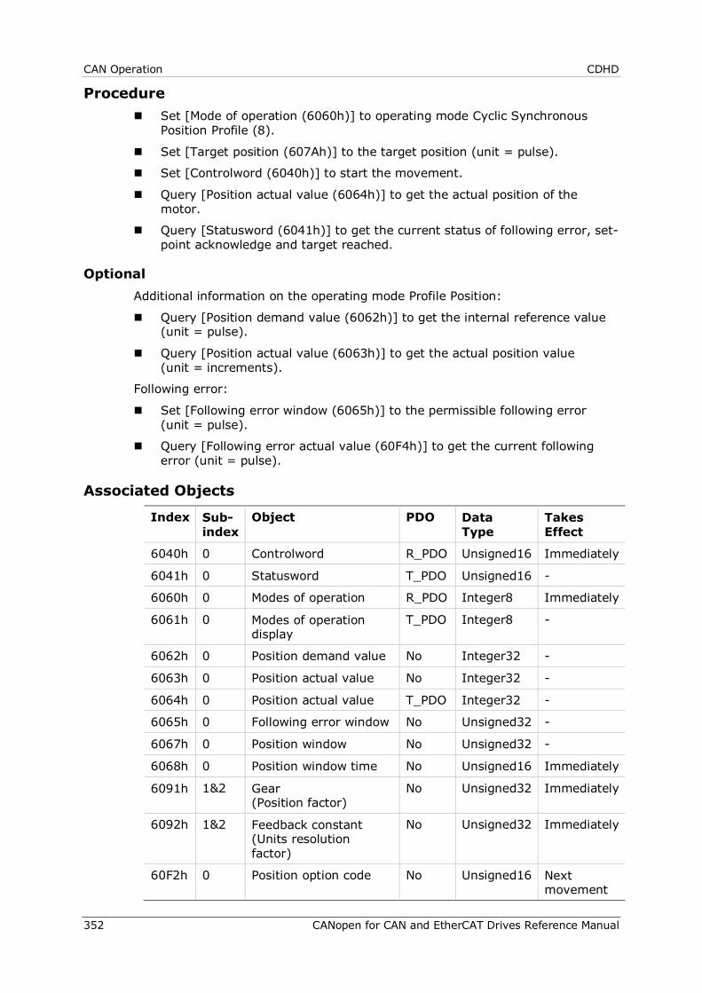
CAN Operation CDHD
352 CANopen for CAN and EtherCAT Drives Reference Manual
Procedure Set [Mode of operation (6060h)] to operating mode Cyclic Synchronous
Position Profile (8).
Set [Target position (607Ah)] to the target position (unit = pulse).
Set [Controlword (6040h)] to start the movement.
Query [Position actual value (6064h)] to get the actual position of the motor.
Query [Statusword (6041h)] to get the current status of following error, set-point acknowledge and target reached.
Optional Additional information on the operating mode Profile Position:
Query [Position demand value (6062h)] to get the internal reference value (unit = pulse).
Query [Position actual value (6063h)] to get the actual position value (unit = increments).
Following error:
Set [Following error window (6065h)] to the permissible following error (unit = pulse).
Query [Following error actual value (60F4h)] to get the current following error (unit = pulse).
Associated Objects
Index Sub-index
Object PDO Data Type
Takes Effect
6040h 0 Controlword R_PDO Unsigned16 Immediately
6041h 0 Statusword T_PDO Unsigned16 -
6060h 0 Modes of operation R_PDO Integer8 Immediately
6061h 0 Modes of operation display
T_PDO Integer8 -
6062h 0 Position demand value No Integer32 -
6063h 0 Position actual value No Integer32 -
6064h 0 Position actual value T_PDO Integer32 -
6065h 0 Following error window No Unsigned32 -
6067h 0 Position window No Unsigned32 -
6068h 0 Position window time No Unsigned16 Immediately
6091h
1&2 Gear (Position factor)
No Unsigned32 Immediately
6092h 1&2 Feedback constant (Units resolution factor)
No Unsigned32 Immediately
60F2h 0 Position option code No Unsigned16 Next movement
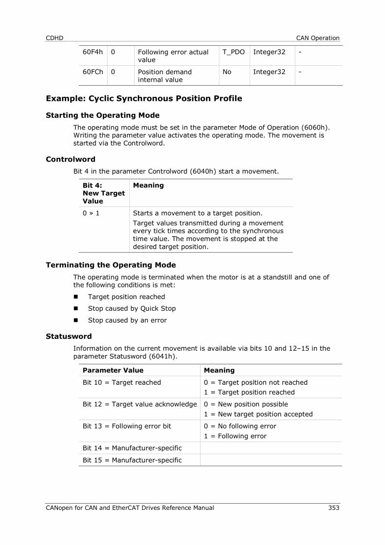
CDHD CAN Operation
CANopen for CAN and EtherCAT Drives Reference Manual 353
60F4h 0 Following error actual value
T_PDO Integer32 -
60FCh 0 Position demand internal value
No Integer32 -
Example: Cyclic Synchronous Position Profile
Starting the Operating Mode The operating mode must be set in the parameter Mode of Operation (6060h). Writing the parameter value activates the operating mode. The movement is started via the Controlword.
Controlword Bit 4 in the parameter Controlword (6040h) start a movement.
Bit 4: New Target Value
Meaning
0 » 1 Starts a movement to a target position. Target values transmitted during a movement every tick times according to the synchronous time value. The movement is stopped at the desired target position.
Terminating the Operating Mode The operating mode is terminated when the motor is at a standstill and one of the following conditions is met:
Target position reached
Stop caused by Quick Stop
Stop caused by an error
Statusword Information on the current movement is available via bits 10 and 12–15 in the parameter Statusword (6041h).
Parameter Value Meaning
Bit 10 = Target reached 0 = Target position not reached 1 = Target position reached
Bit 12 = Target value acknowledge 0 = New position possible 1 = New target position accepted
Bit 13 = Following error bit 0 = No following error 1 = Following error
Bit 14 = Manufacturer-specific
Bit 15 = Manufacturer-specific
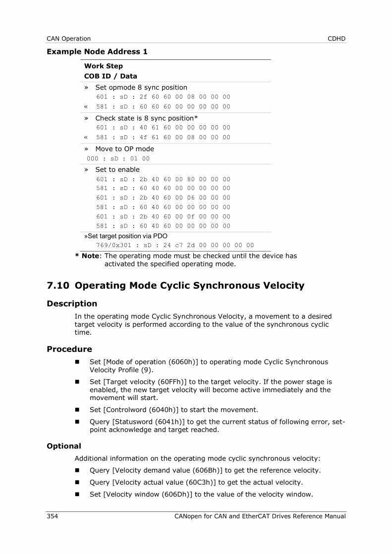
CAN Operation CDHD
354 CANopen for CAN and EtherCAT Drives Reference Manual
Example Node Address 1
Work Step COB ID / Data » Set opmode 8 sync position 601 : sD : 2f 60 60 00 08 00 00 00
« 581 : sD : 60 60 60 00 00 00 00 00
» Check state is 8 sync position* 601 : sD : 40 61 60 00 00 00 00 00
« 581 : sD : 4f 61 60 00 08 00 00 00
» Move to OP mode 000 : sD : 01 00
» Set to enable 601 : sD : 2b 40 60 00 80 00 00 00 581 : sD : 60 40 60 00 00 00 00 00
601 : sD : 2b 40 60 00 06 00 00 00
581 : sD : 60 40 60 00 00 00 00 00
601 : sD : 2b 40 60 00 0f 00 00 00 581 : sD : 60 40 60 00 00 00 00 00
»Set target position via PDO 769/0x301 : sD : 24 c7 2d 00 00 00 00 00
* Note: The operating mode must be checked until the device has activated the specified operating mode.
7.10 Operating Mode Cyclic Synchronous Velocity
Description In the operating mode Cyclic Synchronous Velocity, a movement to a desired target velocity is performed according to the value of the synchronous cyclic time.
Procedure Set [Mode of operation (6060h)] to operating mode Cyclic Synchronous
Velocity Profile (9).
Set [Target velocity (60FFh)] to the target velocity. If the power stage is enabled, the new target velocity will become active immediately and the movement will start.
Set [Controlword (6040h)] to start the movement.
Query [Statusword (6041h)] to get the current status of following error, set-point acknowledge and target reached.
Optional Additional information on the operating mode cyclic synchronous velocity:
Query [Velocity demand value (606Bh)] to get the reference velocity.
Query [Velocity actual value (60C3h)] to get the actual velocity.
Set [Velocity window (606Dh)] to the value of the velocity window.
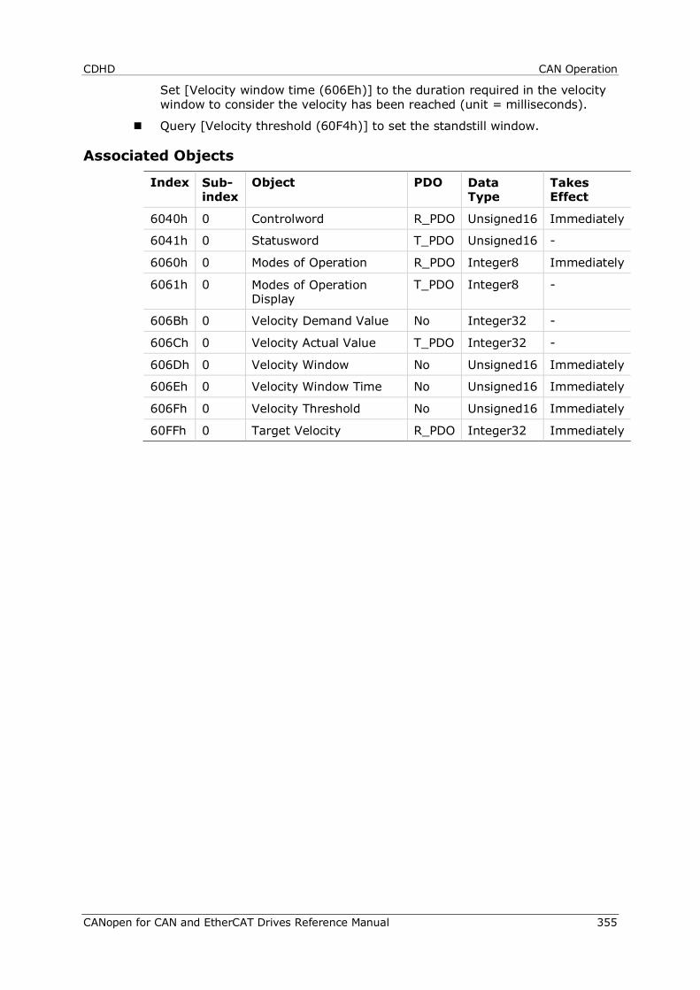
CDHD CAN Operation
CANopen for CAN and EtherCAT Drives Reference Manual 355
Set [Velocity window time (606Eh)] to the duration required in the velocity window to consider the velocity has been reached (unit = milliseconds).
Query [Velocity threshold (60F4h)] to set the standstill window.
Associated Objects
Index Sub-index
Object PDO Data Type
Takes Effect
6040h 0 Controlword R_PDO Unsigned16 Immediately
6041h 0 Statusword T_PDO Unsigned16 -
6060h 0 Modes of Operation R_PDO Integer8 Immediately
6061h 0 Modes of Operation Display
T_PDO Integer8 -
606Bh 0 Velocity Demand Value No Integer32 -
606Ch 0 Velocity Actual Value T_PDO Integer32 -
606Dh 0 Velocity Window No Unsigned16 Immediately
606Eh 0 Velocity Window Time No Unsigned16 Immediately
606Fh 0 Velocity Threshold No Unsigned16 Immediately
60FFh 0 Target Velocity R_PDO Integer32 Immediately
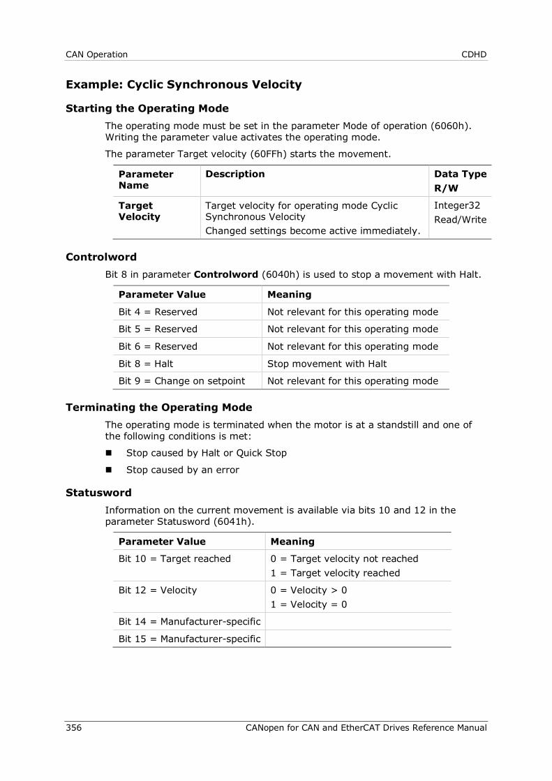
CAN Operation CDHD
356 CANopen for CAN and EtherCAT Drives Reference Manual
Example: Cyclic Synchronous Velocity
Starting the Operating Mode The operating mode must be set in the parameter Mode of operation (6060h). Writing the parameter value activates the operating mode.
The parameter Target velocity (60FFh) starts the movement.
Parameter Name
Description Data Type R/W
Target Velocity
Target velocity for operating mode Cyclic Synchronous Velocity Changed settings become active immediately.
Integer32 Read/Write
Controlword Bit 8 in parameter Controlword (6040h) is used to stop a movement with Halt.
Parameter Value Meaning
Bit 4 = Reserved Not relevant for this operating mode
Bit 5 = Reserved Not relevant for this operating mode
Bit 6 = Reserved Not relevant for this operating mode
Bit 8 = Halt Stop movement with Halt
Bit 9 = Change on setpoint Not relevant for this operating mode
Terminating the Operating Mode The operating mode is terminated when the motor is at a standstill and one of the following conditions is met:
Stop caused by Halt or Quick Stop
Stop caused by an error
Statusword Information on the current movement is available via bits 10 and 12 in the parameter Statusword (6041h).
Parameter Value Meaning
Bit 10 = Target reached 0 = Target velocity not reached 1 = Target velocity reached
Bit 12 = Velocity 0 = Velocity > 0 1 = Velocity = 0
Bit 14 = Manufacturer-specific
Bit 15 = Manufacturer-specific
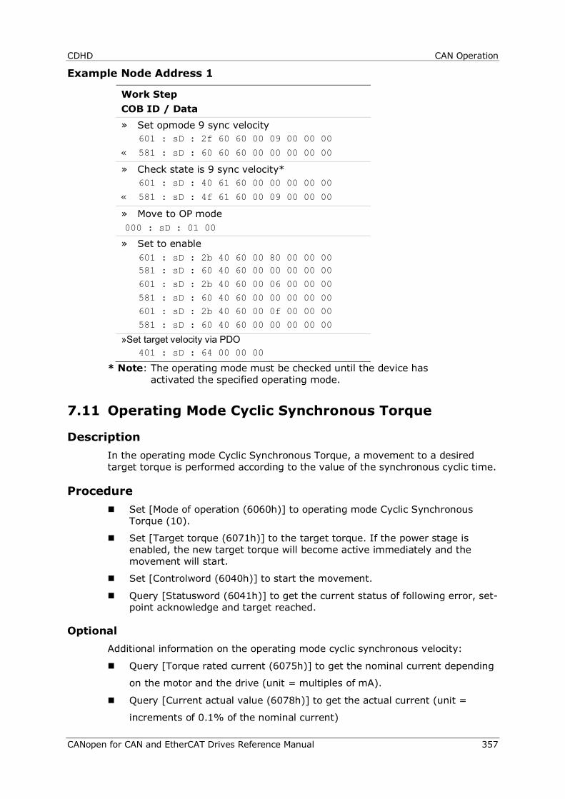
CDHD CAN Operation
CANopen for CAN and EtherCAT Drives Reference Manual 357
Example Node Address 1
Work Step COB ID / Data » Set opmode 9 sync velocity 601 : sD : 2f 60 60 00 09 00 00 00
« 581 : sD : 60 60 60 00 00 00 00 00
» Check state is 9 sync velocity* 601 : sD : 40 61 60 00 00 00 00 00
« 581 : sD : 4f 61 60 00 09 00 00 00
» Move to OP mode 000 : sD : 01 00
» Set to enable 601 : sD : 2b 40 60 00 80 00 00 00 581 : sD : 60 40 60 00 00 00 00 00
601 : sD : 2b 40 60 00 06 00 00 00
581 : sD : 60 40 60 00 00 00 00 00 601 : sD : 2b 40 60 00 0f 00 00 00
581 : sD : 60 40 60 00 00 00 00 00
»Set target velocity via PDO 401 : sD : 64 00 00 00
* Note: The operating mode must be checked until the device has activated the specified operating mode.
7.11 Operating Mode Cyclic Synchronous Torque
Description In the operating mode Cyclic Synchronous Torque, a movement to a desired target torque is performed according to the value of the synchronous cyclic time.
Procedure Set [Mode of operation (6060h)] to operating mode Cyclic Synchronous
Torque (10).
Set [Target torque (6071h)] to the target torque. If the power stage is enabled, the new target torque will become active immediately and the movement will start.
Set [Controlword (6040h)] to start the movement.
Query [Statusword (6041h)] to get the current status of following error, set-point acknowledge and target reached.
Optional Additional information on the operating mode cyclic synchronous velocity:
Query [Torque rated current (6075h)] to get the nominal current depending
on the motor and the drive (unit = multiples of mA).
Query [Current actual value (6078h)] to get the actual current (unit =
increments of 0.1% of the nominal current)

CAN Operation CDHD
358 CANopen for CAN and EtherCAT Drives Reference Manual
Associated Objects
Index Sub-index
Object PDO Data Type
Takes Effect
6040h 0 Controlword R_PDO Unsigned16 Immediately
6041h 0 Statusword T_PDO Unsigned16 -
6060h 0 Modes of Operation R_PDO Integer8 Immediately
6061h 0 Modes of Operation Display
T_PDO Integer8 -
6071h 0 Target Torque R_PDO Integer16 Immediately
6074h 0 Torque demand value T_PDO Integer16 -
6075h 0 Motor rated current No Unsigned32 -
6087h 0 Torque slope No Unsigned32
Example: Cyclic Synchronous Torque
Starting the Operating Mode The operating mode must be set in the parameter Mode of operation (6060h).
Writing the parameter value activates the operating mode.
The parameter Target torque (6071h) starts the movement.
Parameter Name
Description Data Type R/W
Target Torque Target torque for operating mode cyclic synchronous torque. 100.0% corresponds to the continuous stall. In increments of 0.1%. Changed settings become active immediately.
Integer32 Read/Write
Controlword Bit 8 in parameter Controlword (6040h) is used to stop a movement with Halt.
Parameter Value Meaning
Bit 4 = Reserved Not relevant for this operating mode
Bit 5 = Reserved Not relevant for this operating mode
Bit 6 = Reserved Not relevant for this operating mode
Bit 8 = Halt Stop movement with Halt
Bit 9 = Change on setpoint Not relevant for this operating mode
Terminating the Operating Mode The operating mode is terminated when the motor is at a standstill and one of the following conditions is met:
Stop caused by Halt or Quick Stop
Stop caused by an error
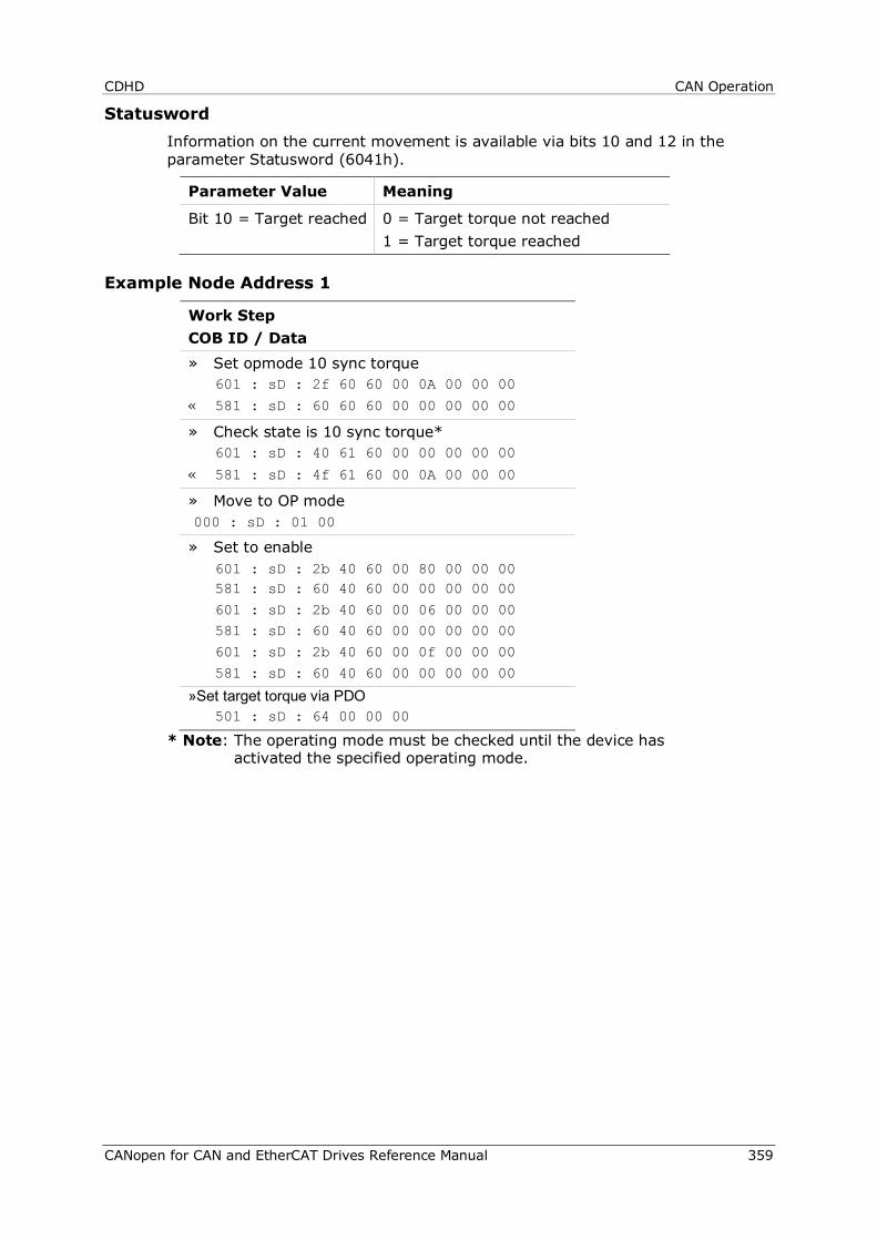
CDHD CAN Operation
CANopen for CAN and EtherCAT Drives Reference Manual 359
Statusword Information on the current movement is available via bits 10 and 12 in the parameter Statusword (6041h).
Parameter Value Meaning
Bit 10 = Target reached 0 = Target torque not reached 1 = Target torque reached
Example Node Address 1
Work Step COB ID / Data » Set opmode 10 sync torque 601 : sD : 2f 60 60 00 0A 00 00 00 « 581 : sD : 60 60 60 00 00 00 00 00
» Check state is 10 sync torque* 601 : sD : 40 61 60 00 00 00 00 00
« 581 : sD : 4f 61 60 00 0A 00 00 00
» Move to OP mode 000 : sD : 01 00
» Set to enable 601 : sD : 2b 40 60 00 80 00 00 00 581 : sD : 60 40 60 00 00 00 00 00
601 : sD : 2b 40 60 00 06 00 00 00 581 : sD : 60 40 60 00 00 00 00 00
601 : sD : 2b 40 60 00 0f 00 00 00
581 : sD : 60 40 60 00 00 00 00 00
»Set target torque via PDO 501 : sD : 64 00 00 00
* Note: The operating mode must be checked until the device has activated the specified operating mode.

Defining Gear Ratio and Feed Constant Parameters CDHD
360 CANopen for CAN and EtherCAT Drives Reference Manual
8 Defining Gear Ratio and Feed Constant Parameters
8.1 Overview
Configuration of the CDHD drive parameters is best performed using the graphic interface software, which requires serial communication.
This chapter describes how to define the values of the feed constant and gear ratio parameters in the graphic interface, so that they will be correctly converted into values recognized by a drive operating in a CANopen network with the following profiles:
CANopen Profiles
Profile Position See example below
Synchronized Position Same as Profile Velocity
Profile Velocity See example below
Synchronized Position Same as Profile Position
Profile Torque Not Applicable
Synchronized Torque Not Applicable
CANopen has two objects for setting the gear ratio and the feed constant conversion factors, each of which has two sub-indices. These objects have four equivalent (VarCom) variables, as shown in the following table.
Description CAN Object VarCom Description
Feed Constant
6092h, sub-index 1
PNUM Feed Constant (Unit Conversion) Numerator
Conversion factors of the user-defined unit. Used to multiply the motor revolution (rotary motors) or the motor pitch (linear motors), according to the type of motor (VarCom MOTORTYPE).
6092h, sub-index 2
PDEN Feed Constant (Unit Conversion) Denominator
Gear Ratio 6091h, sub-index 1
FBGMS Fieldbus Gear Ratio - Motor Shaft Scaling
The conversion factor of the fieldbus device’s motor shaft revolution.
6091h, sub-index 2
FBGDS Fieldbus Gear Ratio - Drive Shaft Scaling
The conversion factor of the fieldbus device’s drive shaft revolution.
In general, you can modify the values of the sub-indices of both objects.
It is usually sufficient, however, to modify only the PNUM value, as shown in the examples presented here.
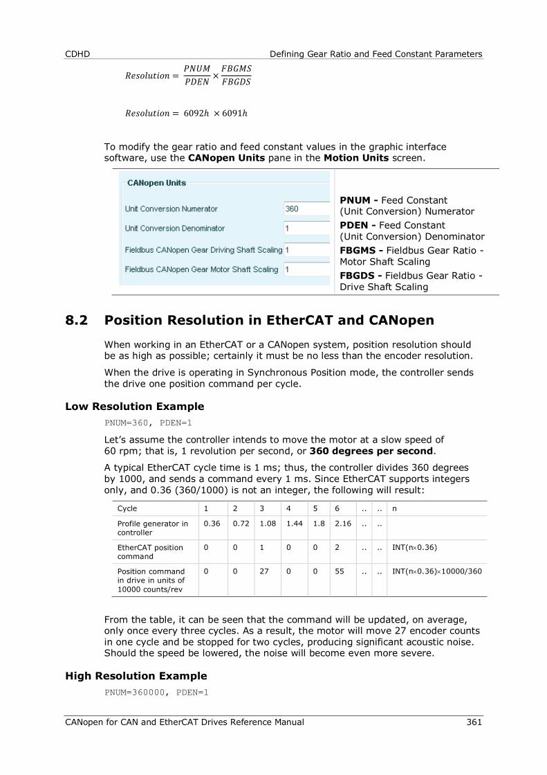
CDHD Defining Gear Ratio and Feed Constant Parameters
CANopen for CAN and EtherCAT Drives Reference Manual 361
𝑅𝑒𝑠𝑜𝑙𝑢𝑡𝑖𝑜𝑛 = 𝑃𝑁𝑈𝑀𝑃𝐷𝐸𝑁 ×
𝐹𝐵𝐺𝑀𝑆𝐹𝐵𝐺𝐷𝑆
𝑅𝑒𝑠𝑜𝑙𝑢𝑡𝑖𝑜𝑛 = 6092ℎ × 6091ℎ
To modify the gear ratio and feed constant values in the graphic interface software, use the CANopen Units pane in the Motion Units screen.
PNUM - Feed Constant (Unit Conversion) Numerator PDEN - Feed Constant (Unit Conversion) Denominator FBGMS - Fieldbus Gear Ratio - Motor Shaft Scaling FBGDS - Fieldbus Gear Ratio - Drive Shaft Scaling
8.2 Position Resolution in EtherCAT and CANopen
When working in an EtherCAT or a CANopen system, position resolution should be as high as possible; certainly it must be no less than the encoder resolution.
When the drive is operating in Synchronous Position mode, the controller sends the drive one position command per cycle.
Low Resolution Example PNUM=360, PDEN=1
Let’s assume the controller intends to move the motor at a slow speed of 60 rpm; that is, 1 revolution per second, or 360 degrees per second.
A typical EtherCAT cycle time is 1 ms; thus, the controller divides 360 degrees by 1000, and sends a command every 1 ms. Since EtherCAT supports integers only, and 0.36 (360/1000) is not an integer, the following will result:
Cycle 1 2 3 4 5 6 .. .. n
Profile generator in controller
0.36 0.72 1.08 1.44 1.8 2.16 .. ..
EtherCAT position command
0 0 1 0 0 2 .. .. INT(n×0.36)
Position command in drive in units of 10000 counts/rev
0 0 27 0 0 55 .. .. INT(n×0.36)×10000/360
From the table, it can be seen that the command will be updated, on average, only once every three cycles. As a result, the motor will move 27 encoder counts in one cycle and be stopped for two cycles, producing significant acoustic noise. Should the speed be lowered, the noise will become even more severe.
High Resolution Example PNUM=360000, PDEN=1
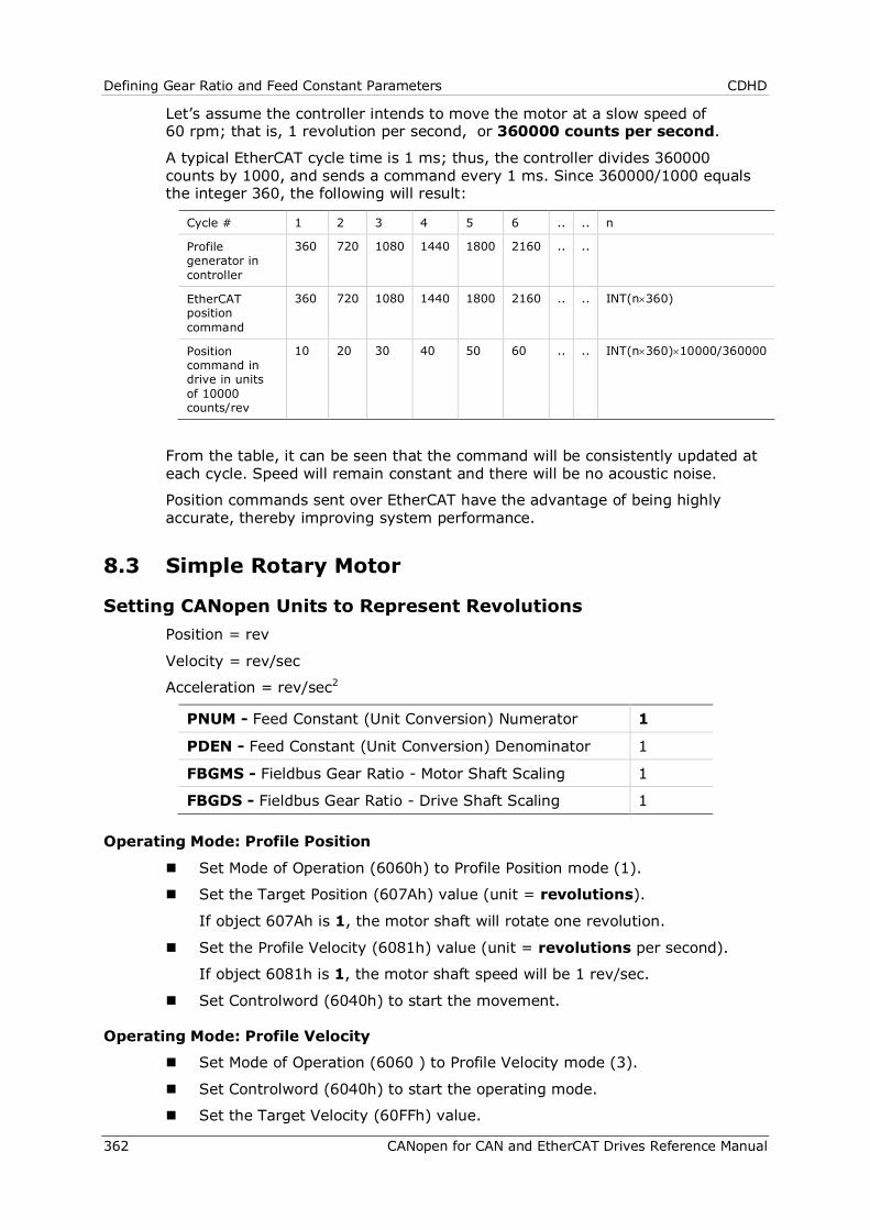
Defining Gear Ratio and Feed Constant Parameters CDHD
362 CANopen for CAN and EtherCAT Drives Reference Manual
Let’s assume the controller intends to move the motor at a slow speed of 60 rpm; that is, 1 revolution per second, or 360000 counts per second.
A typical EtherCAT cycle time is 1 ms; thus, the controller divides 360000 counts by 1000, and sends a command every 1 ms. Since 360000/1000 equals the integer 360, the following will result:
Cycle # 1 2 3 4 5 6 .. .. n
Profile generator in controller
360 720 1080 1440 1800 2160 .. ..
EtherCAT position command
360 720 1080 1440 1800 2160 .. .. INT(n×360)
Position command in drive in units of 10000 counts/rev
10 20 30 40 50 60 .. .. INT(n×360)×10000/360000
From the table, it can be seen that the command will be consistently updated at each cycle. Speed will remain constant and there will be no acoustic noise.
Position commands sent over EtherCAT have the advantage of being highly accurate, thereby improving system performance.
8.3 Simple Rotary Motor
Setting CANopen Units to Represent Revolutions Position = rev
Velocity = rev/sec
Acceleration = rev/sec2
PNUM - Feed Constant (Unit Conversion) Numerator 1
PDEN - Feed Constant (Unit Conversion) Denominator 1
FBGMS - Fieldbus Gear Ratio - Motor Shaft Scaling 1
FBGDS - Fieldbus Gear Ratio - Drive Shaft Scaling 1
Operating Mode: Profile Position
Set Mode of Operation (6060h) to Profile Position mode (1).
Set the Target Position (607Ah) value (unit = revolutions).
If object 607Ah is 1, the motor shaft will rotate one revolution.
Set the Profile Velocity (6081h) value (unit = revolutions per second).
If object 6081h is 1, the motor shaft speed will be 1 rev/sec.
Set Controlword (6040h) to start the movement.
Operating Mode: Profile Velocity
Set Mode of Operation (6060 ) to Profile Velocity mode (3).
Set Controlword (6040h) to start the operating mode.
Set the Target Velocity (60FFh) value.
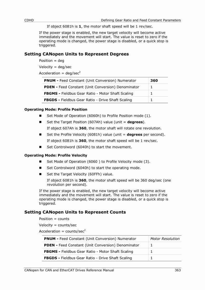
CDHD Defining Gear Ratio and Feed Constant Parameters
CANopen for CAN and EtherCAT Drives Reference Manual 363
If object 6081h is 1, the motor shaft speed will be 1 rev/sec.
If the power stage is enabled, the new target velocity will become active immediately and the movement will start. The value is reset to zero if the operating mode is changed, the power stage is disabled, or a quick stop is triggered.
Setting CANopen Units to Represent Degrees Position = deg
Velocity = deg/sec
Acceleration = deg/sec2
PNUM - Feed Constant (Unit Conversion) Numerator 360
PDEN - Feed Constant (Unit Conversion) Denominator 1
FBGMS - Fieldbus Gear Ratio - Motor Shaft Scaling 1
FBGDS - Fieldbus Gear Ratio - Drive Shaft Scaling 1
Operating Mode: Profile Position
Set Mode of Operation (6060h) to Profile Position mode (1).
Set the Target Position (607Ah) value (unit = degrees).
If object 607Ah is 360, the motor shaft will rotate one revolution.
Set the Profile Velocity (6081h) value (unit = degrees per second).
If object 6081h is 360, the motor shaft speed will be 1 rev/sec.
Set Controlword (6040h) to start the movement.
Operating Mode: Profile Velocity
Set Mode of Operation (6060 ) to Profile Velocity mode (3).
Set Controlword (6040h) to start the operating mode.
Set the Target Velocity (60FFh) value.
If object 6081h is 360, the motor shaft speed will be 360 deg/sec (one revolution per second).
If the power stage is enabled, the new target velocity will become active immediately and the movement will start. The value is reset to zero if the operating mode is changed, the power stage is disabled, or a quick stop is triggered.
Setting CANopen Units to Represent Counts Position = counts
Velocity = counts/sec
Acceleration = counts/sec2
PNUM - Feed Constant (Unit Conversion) Numerator Motor Resolution
PDEN - Feed Constant (Unit Conversion) Denominator 1
FBGMS - Fieldbus Gear Ratio - Motor Shaft Scaling 1
FBGDS - Fieldbus Gear Ratio - Drive Shaft Scaling 1
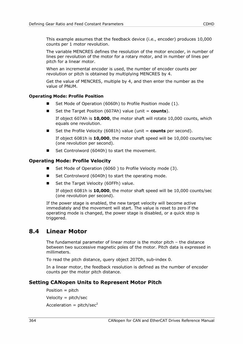
Defining Gear Ratio and Feed Constant Parameters CDHD
364 CANopen for CAN and EtherCAT Drives Reference Manual
This example assumes that the feedback device (i.e., encoder) produces 10,000 counts per 1 motor revolution.
The variable MENCRES defines the resolution of the motor encoder, in number of lines per revolution of the motor for a rotary motor, and in number of lines per pitch for a linear motor.
When an incremental encoder is used, the number of encoder counts per revolution or pitch is obtained by multiplying MENCRES by 4.
Get the value of MENCRES, multiple by 4, and then enter the number as the value of PNUM.
Operating Mode: Profile Position
Set Mode of Operation (6060h) to Profile Position mode (1).
Set the Target Position (607Ah) value (unit = counts).
If object 607Ah is 10,000, the motor shaft will rotate 10,000 counts, which equals one revolution.
Set the Profile Velocity (6081h) value (unit = counts per second).
If object 6081h is 10,000, the motor shaft speed will be 10,000 counts/sec (one revolution per second).
Set Controlword (6040h) to start the movement.
Operating Mode: Profile Velocity Set Mode of Operation (6060 ) to Profile Velocity mode (3).
Set Controlword (6040h) to start the operating mode.
Set the Target Velocity (60FFh) value.
If object 6081h is 10,000, the motor shaft speed will be 10,000 counts/sec (one revolution per second).
If the power stage is enabled, the new target velocity will become active immediately and the movement will start. The value is reset to zero if the operating mode is changed, the power stage is disabled, or a quick stop is triggered.
8.4 Linear Motor
The fundamental parameter of linear motor is the motor pitch – the distance between two successive magnetic poles of the motor. Pitch data is expressed in millimeters.
To read the pitch distance, query object 207Dh, sub-index 0.
In a linear motor, the feedback resolution is defined as the number of encoder counts per the motor pitch distance.
Setting CANopen Units to Represent Motor Pitch Position = pitch
Velocity = pitch/sec
Acceleration = pitch/sec2
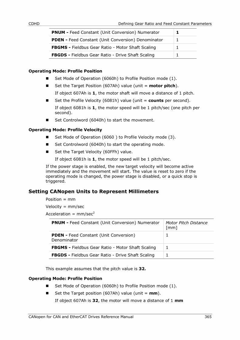
CDHD Defining Gear Ratio and Feed Constant Parameters
CANopen for CAN and EtherCAT Drives Reference Manual 365
PNUM - Feed Constant (Unit Conversion) Numerator 1
PDEN - Feed Constant (Unit Conversion) Denominator 1
FBGMS - Fieldbus Gear Ratio - Motor Shaft Scaling 1
FBGDS - Fieldbus Gear Ratio - Drive Shaft Scaling 1
Operating Mode: Profile Position
Set Mode of Operation (6060h) to Profile Position mode (1).
Set the Target Position (607Ah) value (unit = motor pitch).
If object 607Ah is 1, the motor shaft will move a distance of 1 pitch.
Set the Profile Velocity (6081h) value (unit = counts per second).
If object 6081h is 1, the motor speed will be 1 pitch/sec (one pitch per second).
Set Controlword (6040h) to start the movement.
Operating Mode: Profile Velocity
Set Mode of Operation (6060 ) to Profile Velocity mode (3).
Set Controlword (6040h) to start the operating mode.
Set the Target Velocity (60FFh) value.
If object 6081h is 1, the motor speed will be 1 pitch/sec.
If the power stage is enabled, the new target velocity will become active immediately and the movement will start. The value is reset to zero if the operating mode is changed, the power stage is disabled, or a quick stop is triggered.
Setting CANopen Units to Represent Millimeters Position = mm
Velocity = mm/sec
Acceleration = mm/sec2
PNUM - Feed Constant (Unit Conversion) Numerator Motor Pitch Distance [mm]
PDEN - Feed Constant (Unit Conversion) Denominator
1
FBGMS - Fieldbus Gear Ratio - Motor Shaft Scaling 1
FBGDS - Fieldbus Gear Ratio - Drive Shaft Scaling 1
This example assumes that the pitch value is 32.
Operating Mode: Profile Position
Set Mode of Operation (6060h) to Profile Position mode (1).
Set the Target position (607Ah) value (unit = mm).
If object 607Ah is 32, the motor will move a distance of 1 mm
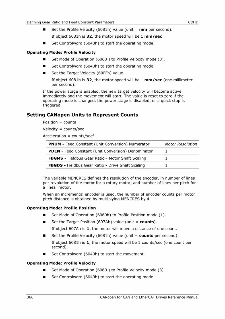
Defining Gear Ratio and Feed Constant Parameters CDHD
366 CANopen for CAN and EtherCAT Drives Reference Manual
Set the Profile Velocity (6081h) value (unit = mm per second).
If object 6081h is 32, the motor speed will be 1 mm/sec
Set Controlword (6040h) to start the operating mode.
Operating Mode: Profile Velocity
Set Mode of Operation (6060 ) to Profile Velocity mode (3).
Set Controlword (6040h) to start the operating mode.
Set the Target Velocity (60FFh) value.
If object 6081h is 32, the motor speed will be 1 mm/sec (one millimeter per second).
If the power stage is enabled, the new target velocity will become active immediately and the movement will start. The value is reset to zero if the operating mode is changed, the power stage is disabled, or a quick stop is triggered.
Setting CANopen Units to Represent Counts Position = counts
Velocity = counts/sec
Acceleration = counts/sec2
PNUM - Feed Constant (Unit Conversion) Numerator Motor Resolution
PDEN - Feed Constant (Unit Conversion) Denominator 1
FBGMS - Fieldbus Gear Ratio - Motor Shaft Scaling 1
FBGDS - Fieldbus Gear Ratio - Drive Shaft Scaling 1
The variable MENCRES defines the resolution of the encoder, in number of lines per revolution of the motor for a rotary motor, and number of lines per pitch for a linear motor.
When an incremental encoder is used, the number of encoder counts per motor pitch distance is obtained by multiplying MENCRES by 4
Operating Mode: Profile Position
Set Mode of Operation (6060h) to Profile Position mode (1).
Set the Target Position (607Ah) value (unit = counts).
If object 607Ah is 1, the motor will move a distance of one count.
Set the Profile Velocity (6081h) value (unit = counts per second).
If object 6081h is 1, the motor speed will be 1 counts/sec (one count per second).
Set Controlword (6040h) to start the movement.
Operating Mode: Profile Velocity
Set Mode of Operation (6060 ) to Profile Velocity mode (3).
Set Controlword (6040h) to start the operating mode.
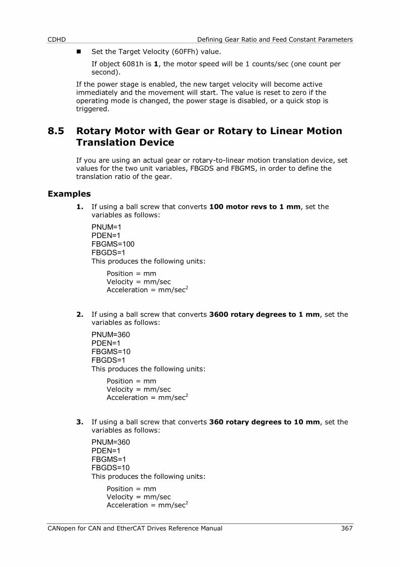
CDHD Defining Gear Ratio and Feed Constant Parameters
CANopen for CAN and EtherCAT Drives Reference Manual 367
Set the Target Velocity (60FFh) value.
If object 6081h is 1, the motor speed will be 1 counts/sec (one count per second).
If the power stage is enabled, the new target velocity will become active immediately and the movement will start. The value is reset to zero if the operating mode is changed, the power stage is disabled, or a quick stop is triggered.
8.5 Rotary Motor with Gear or Rotary to Linear Motion Translation Device
If you are using an actual gear or rotary-to-linear motion translation device, set values for the two unit variables, FBGDS and FBGMS, in order to define the translation ratio of the gear.
Examples 1. If using a ball screw that converts 100 motor revs to 1 mm, set the
variables as follows:
PNUM=1 PDEN=1 FBGMS=100 FBGDS=1 This produces the following units:
Position = mm Velocity = mm/sec Acceleration = mm/sec2
2. If using a ball screw that converts 3600 rotary degrees to 1 mm, set the variables as follows:
PNUM=360 PDEN=1 FBGMS=10 FBGDS=1 This produces the following units:
Position = mm Velocity = mm/sec Acceleration = mm/sec2
3. If using a ball screw that converts 360 rotary degrees to 10 mm, set the variables as follows:
PNUM=360 PDEN=1 FBGMS=1 FBGDS=10 This produces the following units:
Position = mm Velocity = mm/sec Acceleration = mm/sec2
Configuring Horner Controller for Use with CDHD CAN (AC) Drive CDHD
368 CANopen for CAN and EtherCAT Drives Reference Manual
9 Configuring Horner Controller for Use with CDHD CAN (AC) Drive
Notes: Horner controllers have a CAN port that can be used in either CsCAN or CANopen mode. CsCAN is a standard developed by Horner. It provides a network to other units or SCADA systems, and provides a single point of connection to the network for programming, monitoring and troubleshooting. CANopen is a industry recognized standard that enables the connectivity options to a third-party equipment such as drives and IO modules.
Horner Cscape Programmable Logic Controller software combines logic, messaging and networking. It enables programming of graphical ladder diagrams (based on IEC-1131) along with development of the operator interface.
These configuration instructions assume the Horner controller and CDHD CAN drive are operating and communicating according to CANopen protocol.
9.1 Overview
This chapter explains how to configure the CDHD CAN servo drive for communication and operation with the Horner controller on a CAN network.
The application system consists of the following elements:
CDHD CAN servo drive, servo motor, and ServoStudio software.
Horner controller with CAN communication port, and Horner Cscape software.
9.2 CDHD Hardware and Software Settings
Refer to chapter Cabling and Setup.The diagram in Figure 2-1 shows a setup with a Horner controller.
Make sure all hardware settings are in accordance with the instructions in the following sections.
Hardware Configuration
Node Address
Termination Resistor Switch
Fieldbus Communication
CANopen/CoE Bit Rate
Feedback Resolution
Synchronization Mode
Fieldbus Interpolation Time
Make sure the correct *.eds file is installed in the controller.
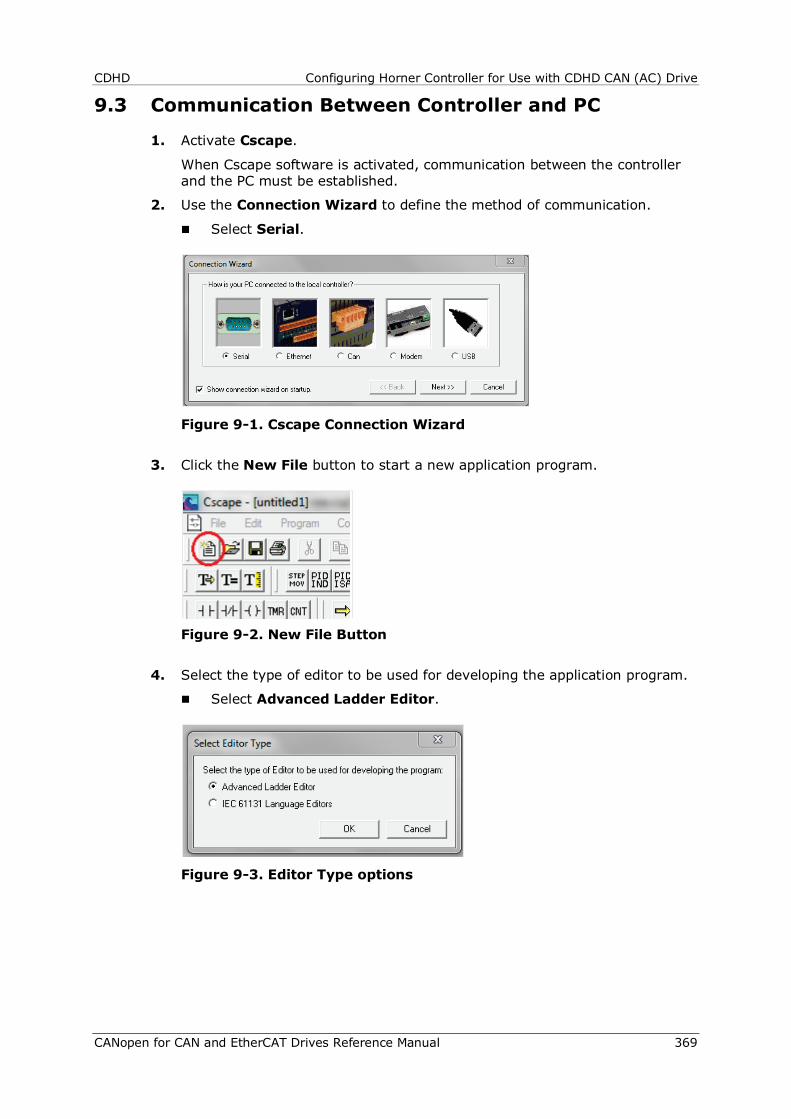
CDHD Configuring Horner Controller for Use with CDHD CAN (AC) Drive
CANopen for CAN and EtherCAT Drives Reference Manual 369
9.3 Communication Between Controller and PC
1. Activate Cscape.
When Cscape software is activated, communication between the controller and the PC must be established.
2. Use the Connection Wizard to define the method of communication.
Select Serial.
Figure 9-1. Cscape Connection Wizard
3. Click the New File button to start a new application program.
Figure 9-2. New File Button
4. Select the type of editor to be used for developing the application program.
Select Advanced Ladder Editor.
Figure 9-3. Editor Type options
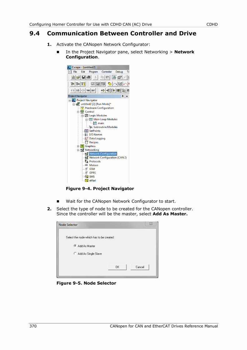
Configuring Horner Controller for Use with CDHD CAN (AC) Drive CDHD
370 CANopen for CAN and EtherCAT Drives Reference Manual
9.4 Communication Between Controller and Drive
1. Activate the CANopen Network Configurator:
In the Project Navigator pane, select Networking > Network Configuration.
Figure 9-4. Project Navigator
Wait for the CANopen Network Configurator to start.
2. Select the type of node to be created for the CANopen controller. Since the controller will be the master, select Add As Master.
Figure 9-5. Node Selector
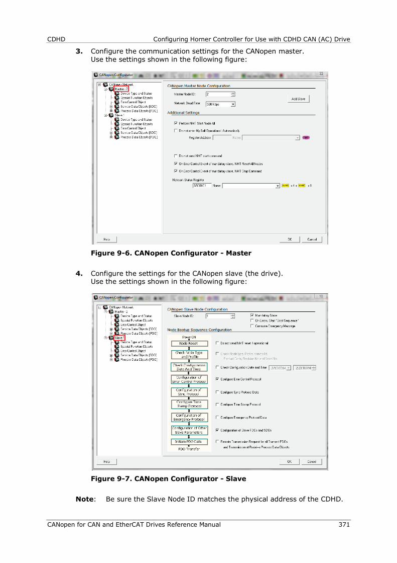
CDHD Configuring Horner Controller for Use with CDHD CAN (AC) Drive
CANopen for CAN and EtherCAT Drives Reference Manual 371
3. Configure the communication settings for the CANopen master. Use the settings shown in the following figure:
Figure 9-6. CANopen Configurator - Master
4. Configure the settings for the CANopen slave (the drive). Use the settings shown in the following figure:
Figure 9-7. CANopen Configurator - Slave
Note: Be sure the Slave Node ID matches the physical address of the CDHD.
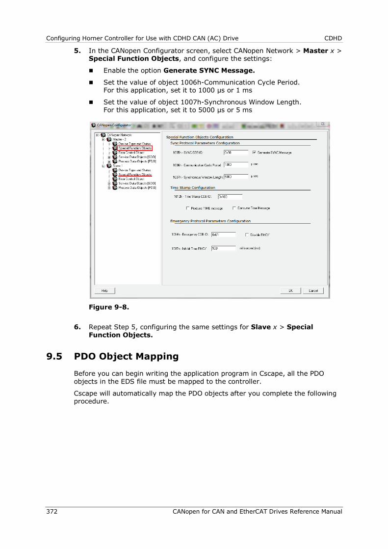
Configuring Horner Controller for Use with CDHD CAN (AC) Drive CDHD
372 CANopen for CAN and EtherCAT Drives Reference Manual
5. In the CANopen Configurator screen, select CANopen Network > Master x > Special Function Objects, and configure the settings:
Enable the option Generate SYNC Message.
Set the value of object 1006h-Communication Cycle Period. For this application, set it to 1000 µs or 1 ms
Set the value of object 1007h-Synchronous Window Length. For this application, set it to 5000 µs or 5 ms
Figure 9-8.
6. Repeat Step 5, configuring the same settings for Slave x > Special Function Objects.
9.5 PDO Object Mapping
Before you can begin writing the application program in Cscape, all the PDO objects in the EDS file must be mapped to the controller.
Cscape will automatically map the PDO objects after you complete the following procedure.

CDHD Configuring Horner Controller for Use with CDHD CAN (AC) Drive
CANopen for CAN and EtherCAT Drives Reference Manual 373
1. Activate Cscape.
2. From the menu bar, select Program > Motion Configuration.
Figure 9-9.
3. In the Network status register field, enter %R0100, and press Add.
Figure 9-10.
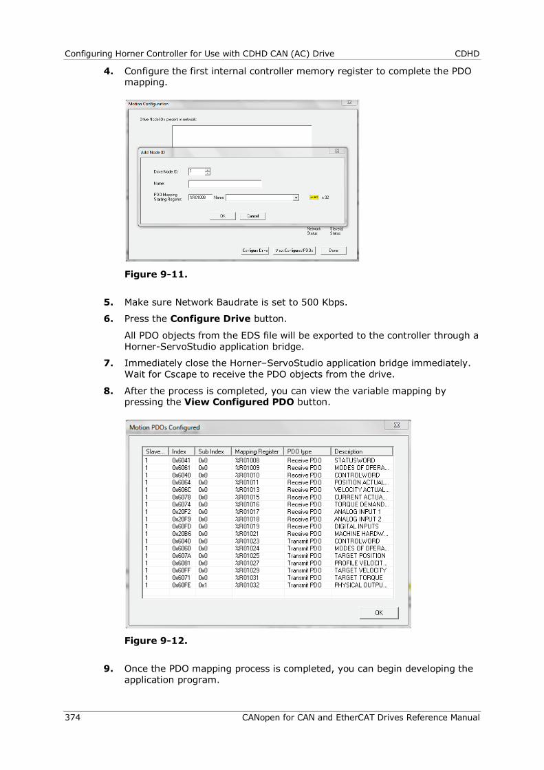
Configuring Horner Controller for Use with CDHD CAN (AC) Drive CDHD
374 CANopen for CAN and EtherCAT Drives Reference Manual
4. Configure the first internal controller memory register to complete the PDO mapping.
Figure 9-11.
5. Make sure Network Baudrate is set to 500 Kbps.
6. Press the Configure Drive button.
All PDO objects from the EDS file will be exported to the controller through a Horner-ServoStudio application bridge.
7. Immediately close the Horner–ServoStudio application bridge immediately. Wait for Cscape to receive the PDO objects from the drive.
8. After the process is completed, you can view the variable mapping by pressing the View Configured PDO button.
Figure 9-12.
9. Once the PDO mapping process is completed, you can begin developing the application program.
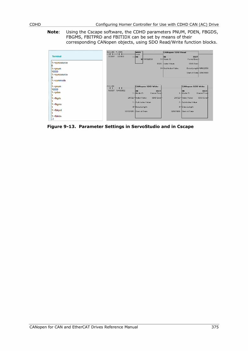
CDHD Configuring Horner Controller for Use with CDHD CAN (AC) Drive
CANopen for CAN and EtherCAT Drives Reference Manual 375
Note: Using the Cscape software, the CDHD parameters PNUM, PDEN, FBGDS, FBGMS, FBITPRD and FBITIDX can be set by means of their corresponding CANopen objects, using SDO Read/Write function blocks.
Figure 9-13. Parameter Settings in ServoStudio and in Cscape
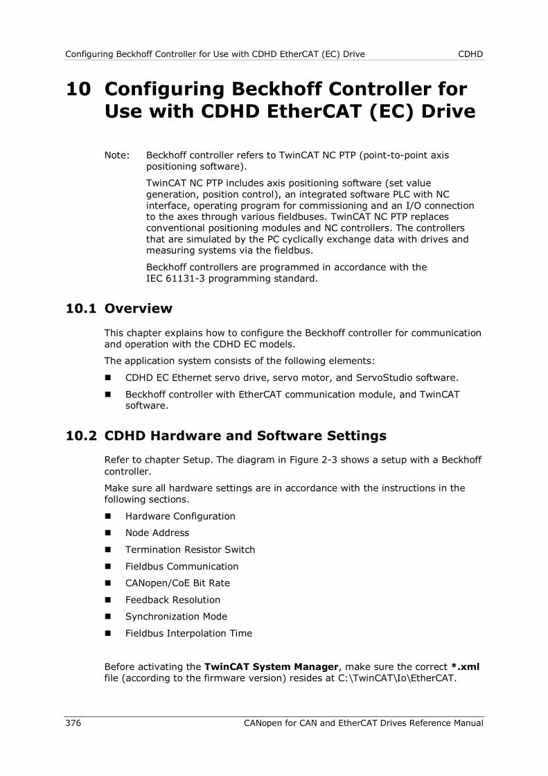
Configuring Beckhoff Controller for Use with CDHD EtherCAT (EC) Drive CDHD
376 CANopen for CAN and EtherCAT Drives Reference Manual
10 Configuring Beckhoff Controller for Use with CDHD EtherCAT (EC) Drive
Note: Beckhoff controller refers to TwinCAT NC PTP (point-to-point axis positioning software).
TwinCAT NC PTP includes axis positioning software (set value generation, position control), an integrated software PLC with NC interface, operating program for commissioning and an I/O connection to the axes through various fieldbuses. TwinCAT NC PTP replaces conventional positioning modules and NC controllers. The controllers that are simulated by the PC cyclically exchange data with drives and measuring systems via the fieldbus.
Beckhoff controllers are programmed in accordance with the IEC 61131-3 programming standard.
10.1 Overview
This chapter explains how to configure the Beckhoff controller for communication and operation with the CDHD EC models.
The application system consists of the following elements:
CDHD EC Ethernet servo drive, servo motor, and ServoStudio software.
Beckhoff controller with EtherCAT communication module, and TwinCAT software.
10.2 CDHD Hardware and Software Settings
Refer to chapter Setup. The diagram in Figure 2-3 shows a setup with a Beckhoff controller.
Make sure all hardware settings are in accordance with the instructions in the following sections.
Hardware Configuration
Node Address
Termination Resistor Switch
Fieldbus Communication
CANopen/CoE Bit Rate
Feedback Resolution
Synchronization Mode
Fieldbus Interpolation Time
Before activating the TwinCAT System Manager, make sure the correct *.xml file (according to the firmware version) resides at C:\TwinCAT\Io\EtherCAT.
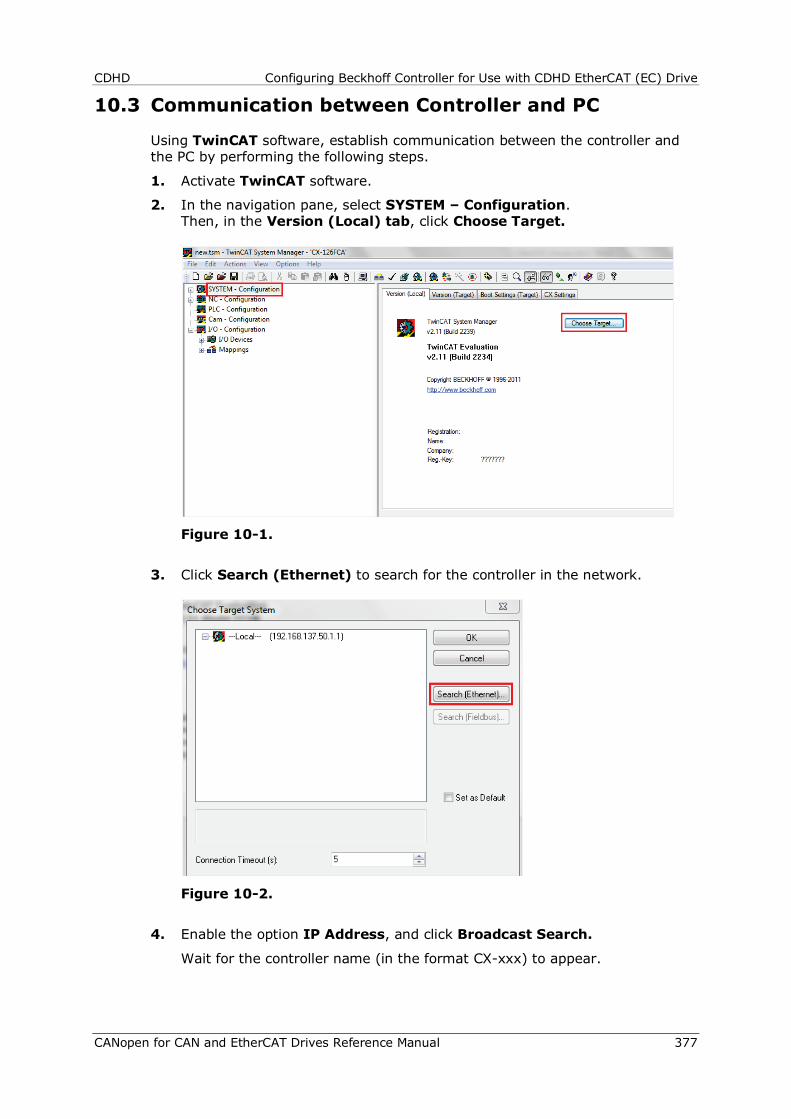
CDHD Configuring Beckhoff Controller for Use with CDHD EtherCAT (EC) Drive
CANopen for CAN and EtherCAT Drives Reference Manual 377
10.3 Communication between Controller and PC
Using TwinCAT software, establish communication between the controller and the PC by performing the following steps.
1. Activate TwinCAT software.
2. In the navigation pane, select SYSTEM – Configuration. Then, in the Version (Local) tab, click Choose Target.
Figure 10-1.
3. Click Search (Ethernet) to search for the controller in the network.
Figure 10-2.
4. Enable the option IP Address, and click Broadcast Search.
Wait for the controller name (in the format CX-xxx) to appear.
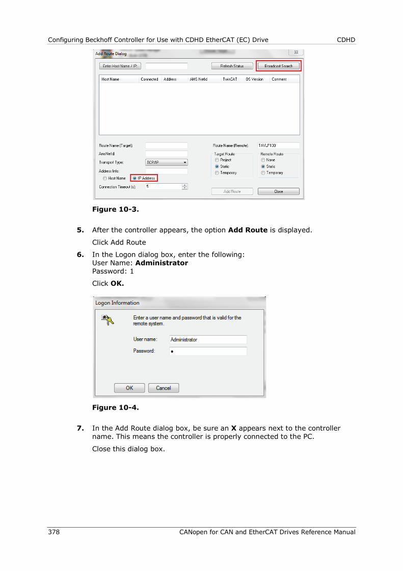
Configuring Beckhoff Controller for Use with CDHD EtherCAT (EC) Drive CDHD
378 CANopen for CAN and EtherCAT Drives Reference Manual
Figure 10-3.
5. After the controller appears, the option Add Route is displayed.
Click Add Route
6. In the Logon dialog box, enter the following: User Name: Administrator Password: 1
Click OK.
Figure 10-4.
7. In the Add Route dialog box, be sure an X appears next to the controller name. This means the controller is properly connected to the PC.
Close this dialog box.
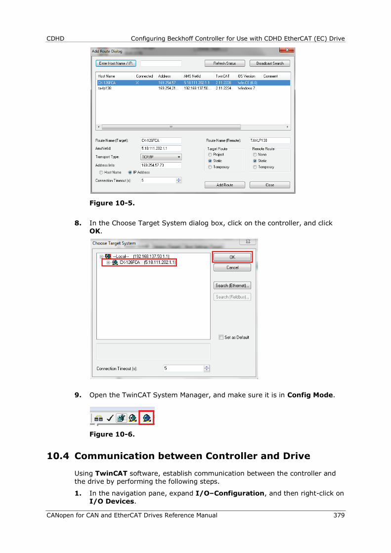
CDHD Configuring Beckhoff Controller for Use with CDHD EtherCAT (EC) Drive
CANopen for CAN and EtherCAT Drives Reference Manual 379
Figure 10-5.
8. In the Choose Target System dialog box, click on the controller, and click OK.
9. Open the TwinCAT System Manager, and make sure it is in Config Mode.
Figure 10-6.
10.4 Communication between Controller and Drive
Using TwinCAT software, establish communication between the controller and the drive by performing the following steps.
1. In the navigation pane, expand I/O–Configuration, and then right-click on I/O Devices.
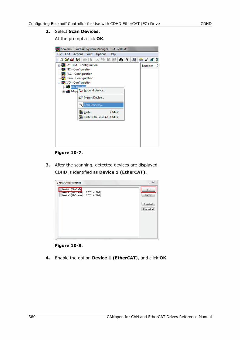
Configuring Beckhoff Controller for Use with CDHD EtherCAT (EC) Drive CDHD
380 CANopen for CAN and EtherCAT Drives Reference Manual
2. Select Scan Devices.
At the prompt, click OK.
Figure 10-7.
3. After the scanning, detected devices are displayed.
CDHD is identified as Device 1 (EtherCAT).
Figure 10-8.
4. Enable the option Device 1 (EtherCAT), and click OK.
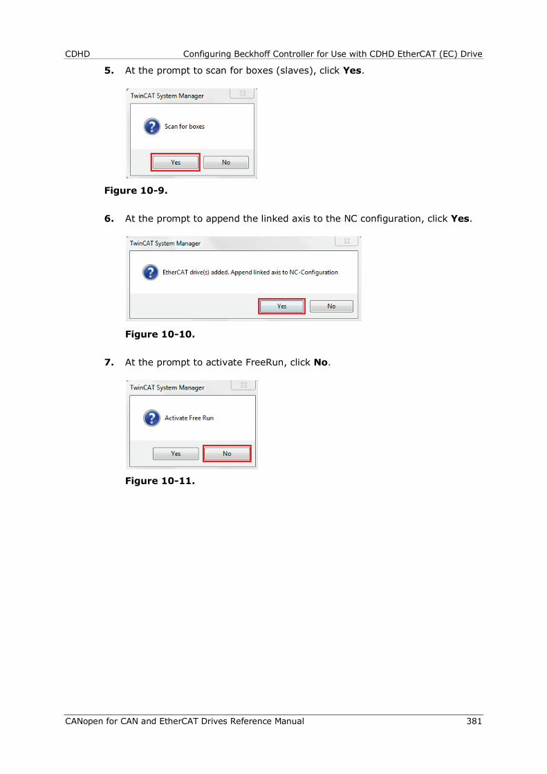
CDHD Configuring Beckhoff Controller for Use with CDHD EtherCAT (EC) Drive
CANopen for CAN and EtherCAT Drives Reference Manual 381
5. At the prompt to scan for boxes (slaves), click Yes.
Figure 10-9.
6. At the prompt to append the linked axis to the NC configuration, click Yes.
Figure 10-10.
7. At the prompt to activate FreeRun, click No.
Figure 10-11.

Configuring Beckhoff Controller for Use with CDHD EtherCAT (EC) Drive CDHD
382 CANopen for CAN and EtherCAT Drives Reference Manual
8. At the end of this procedure, Device 1 (EtherCAT) is displayed in the navigation pane, with all components (TPDO and RPDO) listed and automatically linked to NC–Configuration>Axis 1.
Figure 10-12.
10.5 Generating Motion
Setup for Motion 1. Open the TwinCAT System Manager, and make sure it is in Config Mode.
Figure 10-13.
2. In the navigation pane, expand SYSTEM–Configuration, and select Real Time Settings.
In the Settings tab, select Base Time = 1 ms.
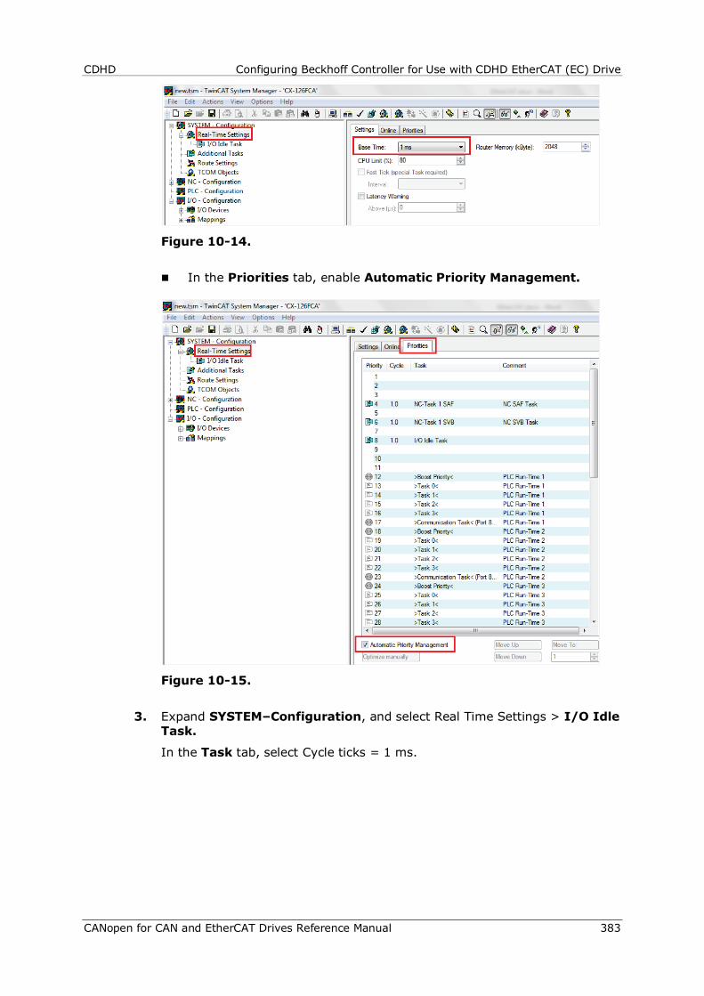
CDHD Configuring Beckhoff Controller for Use with CDHD EtherCAT (EC) Drive
CANopen for CAN and EtherCAT Drives Reference Manual 383
Figure 10-14.
In the Priorities tab, enable Automatic Priority Management.
Figure 10-15.
3. Expand SYSTEM–Configuration, and select Real Time Settings > I/O Idle Task.
In the Task tab, select Cycle ticks = 1 ms.
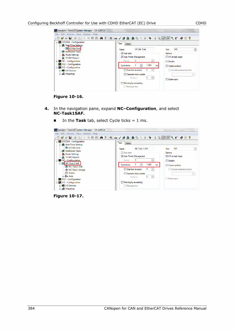
Configuring Beckhoff Controller for Use with CDHD EtherCAT (EC) Drive CDHD
384 CANopen for CAN and EtherCAT Drives Reference Manual
Figure 10-16.
4. In the navigation pane, expand NC–Configuration, and select NC-Task1SAF.
In the Task tab, select Cycle ticks = 1 ms.
Figure 10-17.
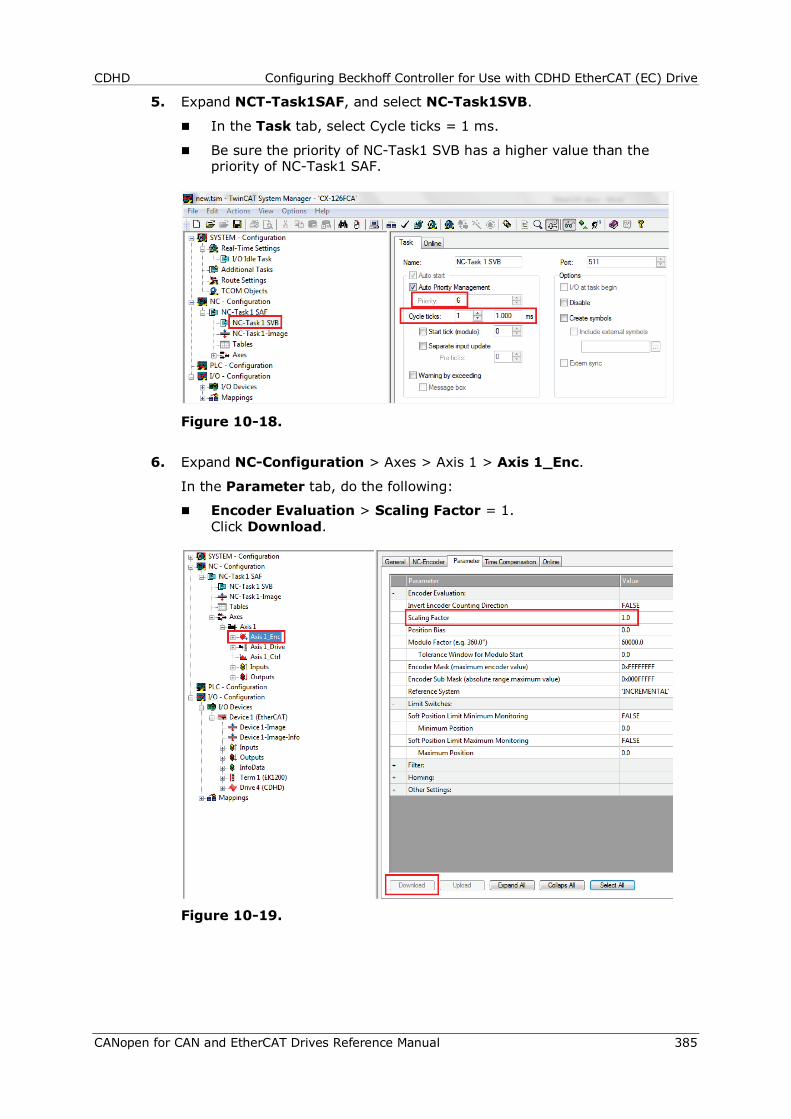
CDHD Configuring Beckhoff Controller for Use with CDHD EtherCAT (EC) Drive
CANopen for CAN and EtherCAT Drives Reference Manual 385
5. Expand NCT-Task1SAF, and select NC-Task1SVB.
In the Task tab, select Cycle ticks = 1 ms.
Be sure the priority of NC-Task1 SVB has a higher value than the priority of NC-Task1 SAF.
Figure 10-18.
6. Expand NC-Configuration > Axes > Axis 1 > Axis 1_Enc.
In the Parameter tab, do the following:
Encoder Evaluation > Scaling Factor = 1. Click Download.
Figure 10-19.
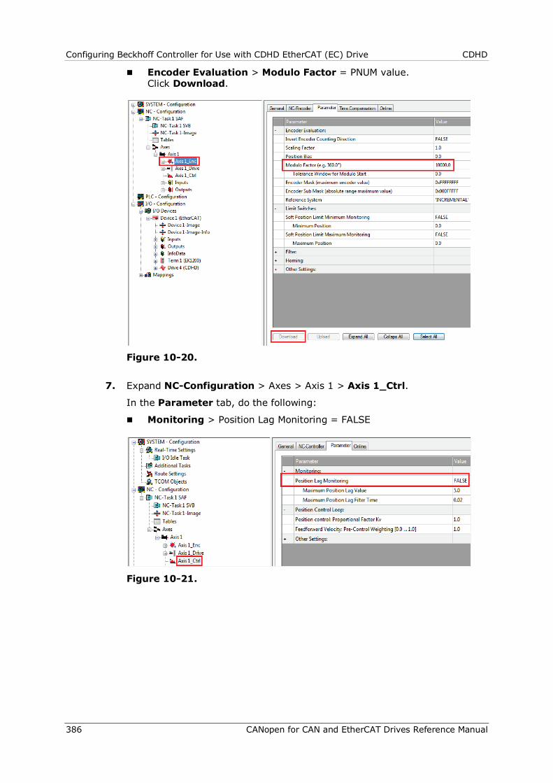
Configuring Beckhoff Controller for Use with CDHD EtherCAT (EC) Drive CDHD
386 CANopen for CAN and EtherCAT Drives Reference Manual
Encoder Evaluation > Modulo Factor = PNUM value. Click Download.
Figure 10-20.
7. Expand NC-Configuration > Axes > Axis 1 > Axis 1_Ctrl.
In the Parameter tab, do the following:
Monitoring > Position Lag Monitoring = FALSE
Figure 10-21.
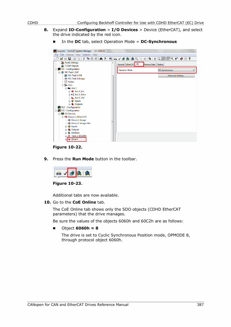
CDHD Configuring Beckhoff Controller for Use with CDHD EtherCAT (EC) Drive
CANopen for CAN and EtherCAT Drives Reference Manual 387
8. Expand IO-Configuration > I/O Devices > Device (EtherCAT), and select the drive indicated by the red icon.
In the DC tab, select Operation Mode = DC-Synchronous
Figure 10-22.
9. Press the Run Mode button in the toolbar.
Figure 10-23.
Additional tabs are now available.
10. Go to the CoE Online tab.
The CoE Online tab shows only the SDO objects (CDHD EtherCAT parameters) that the drive manages.
Be sure the values of the objects 6060h and 60C2h are as follows:
Object 6060h = 8
The drive is set to Cyclic Synchronous Position mode, OPMODE 8, through protocol object 6060h.
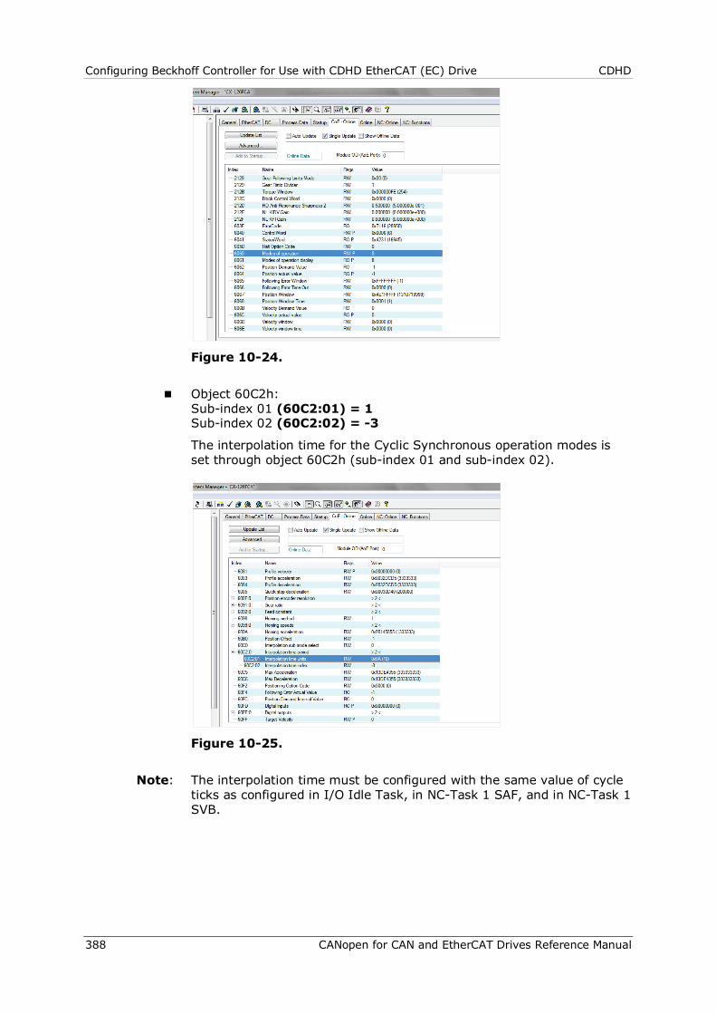
Configuring Beckhoff Controller for Use with CDHD EtherCAT (EC) Drive CDHD
388 CANopen for CAN and EtherCAT Drives Reference Manual
Figure 10-24.
Object 60C2h: Sub-index 01 (60C2:01) = 1 Sub-index 02 (60C2:02) = -3
The interpolation time for the Cyclic Synchronous operation modes is set through object 60C2h (sub-index 01 and sub-index 02).
Figure 10-25.
Note: The interpolation time must be configured with the same value of cycle ticks as configured in I/O Idle Task, in NC-Task 1 SAF, and in NC-Task 1 SVB.
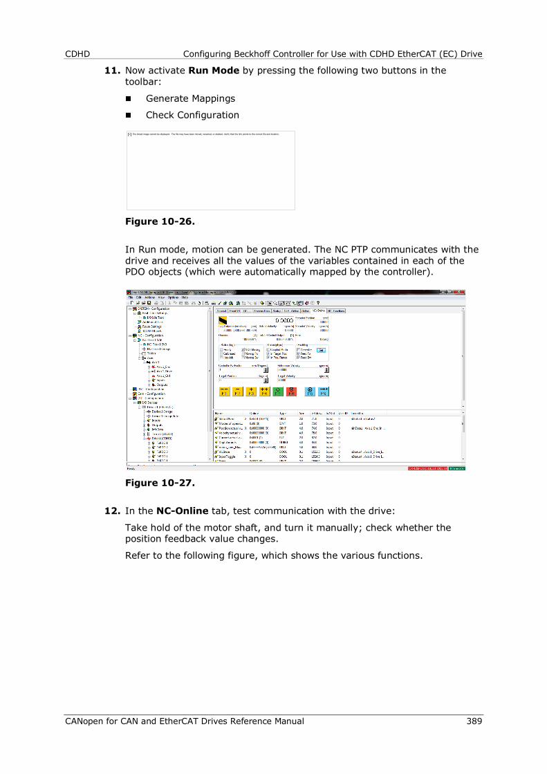
CDHD Configuring Beckhoff Controller for Use with CDHD EtherCAT (EC) Drive
CANopen for CAN and EtherCAT Drives Reference Manual 389
11. Now activate Run Mode by pressing the following two buttons in the toolbar:
Generate Mappings
Check Configuration
Figure 10-26.
In Run mode, motion can be generated. The NC PTP communicates with the drive and receives all the values of the variables contained in each of the PDO objects (which were automatically mapped by the controller).
Figure 10-27.
12. In the NC-Online tab, test communication with the drive:
Take hold of the motor shaft, and turn it manually; check whether the position feedback value changes.
Refer to the following figure, which shows the various functions.
The linked image cannot be displayed. The file may have been moved, renamed, or deleted. Verify that the link points to the correct file and location.
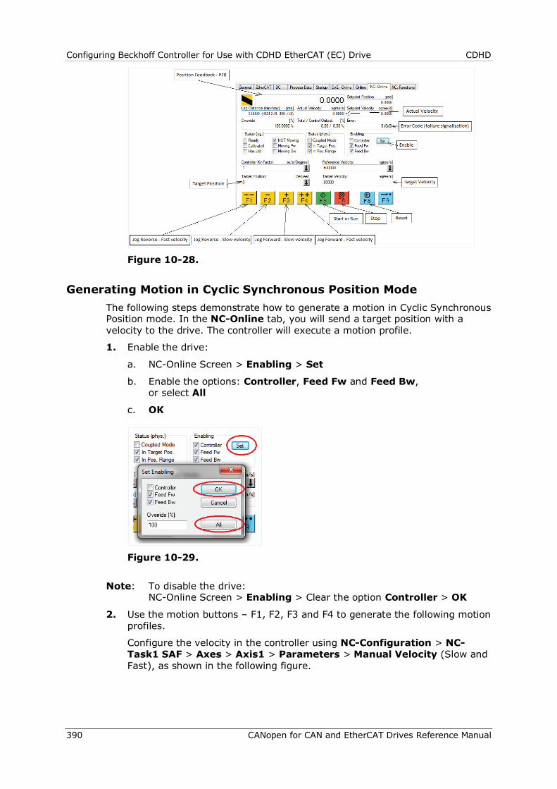
Configuring Beckhoff Controller for Use with CDHD EtherCAT (EC) Drive CDHD
390 CANopen for CAN and EtherCAT Drives Reference Manual
Figure 10-28.
Generating Motion in Cyclic Synchronous Position Mode The following steps demonstrate how to generate a motion in Cyclic Synchronous Position mode. In the NC-Online tab, you will send a target position with a velocity to the drive. The controller will execute a motion profile.
1. Enable the drive:
a. NC-Online Screen > Enabling > Set
b. Enable the options: Controller, Feed Fw and Feed Bw, or select All
c. OK
Figure 10-29.
Note: To disable the drive: NC-Online Screen > Enabling > Clear the option Controller > OK
2. Use the motion buttons – F1, F2, F3 and F4 to generate the following motion profiles.
Configure the velocity in the controller using NC-Configuration > NC-Task1 SAF > Axes > Axis1 > Parameters > Manual Velocity (Slow and Fast), as shown in the following figure.

CDHD Configuring Beckhoff Controller for Use with CDHD EtherCAT (EC) Drive
CANopen for CAN and EtherCAT Drives Reference Manual 391
Figure 10-30.
F1: Sends a jog command in the negative direction (CCW) with a fast velocity.
F2: Sends a jog command in the negative direction (CCW) with slow velocity.
F3: Sends a jog command in the positive direction (CW) with slow velocity.
F4: Sends a jog command in the positive direction (CW) with fast velocity.
3. Set values for Target Position and Target Velocity as shown in the following figure.
Figure 10-31.

Configuring Beckhoff Controller for Use with CDHD EtherCAT (EC) Drive CDHD
392 CANopen for CAN and EtherCAT Drives Reference Manual
4. Press F5 (green button) to start the motion profile in Synchronous Position mode.
Press F6 (red button) to stop the motion.
Press F8 (blue button) to clear any faults.
The graph in the following figure reflects the motion performed:
Figure 10-32.
Brown line = Position feedback – PFB
Green line = Point to point generator velocity command - PTPVCMD
Blue line = Position error – PE
X axis = milliseconds, Y axis = counts
Generating Absolute and Relative Motion To generate absolute or relative motion in Position Profile mode, refer to the following two figures, and do the following:
1. Go to the Functions tab.
2. Configure the target position, the target velocity, the acceleration and deceleration, and the jerk of the motion.
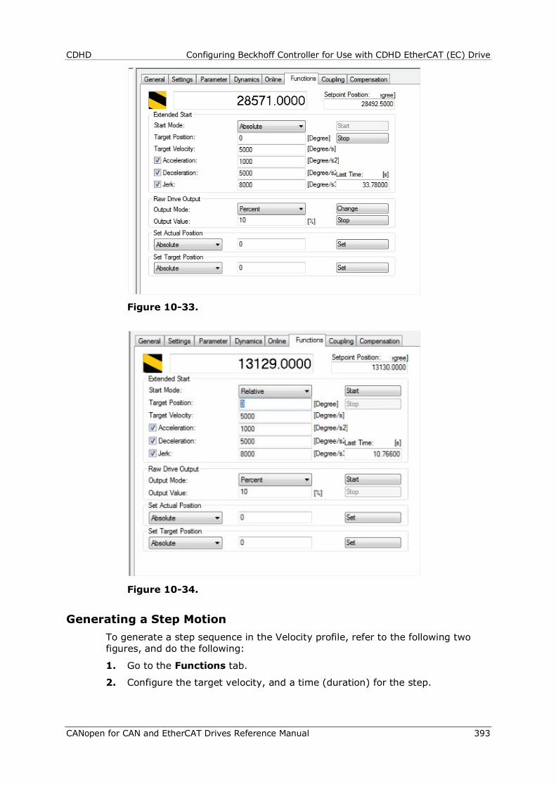
CDHD Configuring Beckhoff Controller for Use with CDHD EtherCAT (EC) Drive
CANopen for CAN and EtherCAT Drives Reference Manual 393
Figure 10-33.
Figure 10-34.
Generating a Step Motion To generate a step sequence in the Velocity profile, refer to the following two figures, and do the following:
1. Go to the Functions tab.
2. Configure the target velocity, and a time (duration) for the step.
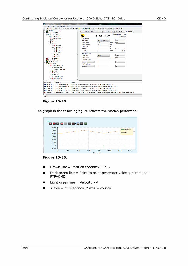
Configuring Beckhoff Controller for Use with CDHD EtherCAT (EC) Drive CDHD
394 CANopen for CAN and EtherCAT Drives Reference Manual
Figure 10-35.
The graph in the following figure reflects the motion performed:
Figure 10-36.
Brown line = Position feedback – PFB
Dark green line = Point to point generator velocity command - PTPVCMD
Light green line = Velocity - V
X axis = milliseconds, Y axis = counts
CDHD Configuring Beckhoff Controller for Use with CDHD EtherCAT (EC) Drive
CANopen for CAN and EtherCAT Drives Reference Manual 395
Configuring Keba Controller for Use with CDHD EtherCAT (EC) Drive CDHD
396 CANopen for CAN and EtherCAT Drives Reference Manual
11 Configuring Keba Controller for Use with CDHD EtherCAT (EC) Drive
To configure the Keba motion controller for use with CDHD EtherCAT drive, a customized set of files need to be installed on the PC.
To obtain these files, and for assistance with the installation and configuration, contact Servotronix technical support.
CustomDrivesIO
Extract all the files to the folder:
C:\Kemro\KeStudioV2.3\Targets\KeMotion_CP24xCP25x_02.60\io\ CustomDrives\Flexy2.0_EtherCatDrive
McCustomDriveLibrary
Extract the file to the library folder, and overwrite the existing file:
C:\Kemro\KeStudio V2.3\Targets\KeMotion_CP24xCP25x_02.60\lib
Note: The folder KeMotion_CP24xCP25x_02.60 may be named differently, depending on the software installation.
Once these files have been put in place, the PLC configuration can be performed.
When prompted for the drive type, select CDHD.

CDHD Configuring Keba Controller for Use with CDHD EtherCAT (EC) Drive
CANopen for CAN and EtherCAT Drives Reference Manual 397
Configuring softMC Controller for Use with CDHD EtherCAT (EC) Drive CDHD
398 CANopen for CAN and EtherCAT Drives Reference Manual
12 Configuring softMC Controller for Use with CDHD EtherCAT (EC) Drive
Information on configuring the softMC controller for use with CDHD can be found in the softMC documentation wiki:
The articles should be accessed and read in the following order:
1. http://softmc.servotronix.com/wiki/Category:EtherCAT:EC_SETUP
2. http://softmc.servotronix.com/wiki/EtherCAT:CDHD_CONFIGURE
3. http://softmc.servotronix.com/wiki/EtherCAT:EC_INSTALL_STX_CDHD
To login to the softMC wiki:
Username: softMC
Password: Documentation
For additional assistance with the installation and configuration, contact Servotronix technical support.

CDHD Configuring softMC Controller for Use with CDHD EtherCAT (EC) Drive
CANopen for CAN and EtherCAT Drives Reference Manual 399
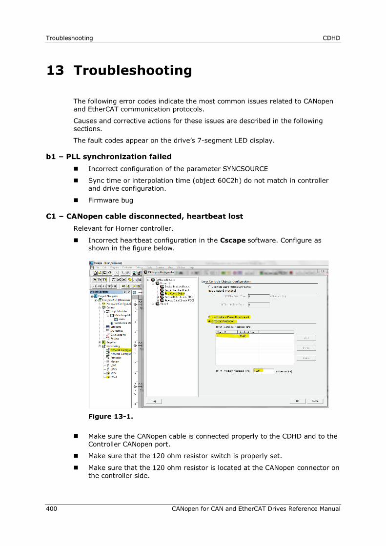
Troubleshooting CDHD
400 CANopen for CAN and EtherCAT Drives Reference Manual
13 Troubleshooting
The following error codes indicate the most common issues related to CANopen and EtherCAT communication protocols.
Causes and corrective actions for these issues are described in the following sections.
The fault codes appear on the drive’s 7-segment LED display.
b1 – PLL synchronization failed Incorrect configuration of the parameter SYNCSOURCE
Sync time or interpolation time (object 60C2h) do not match in controller and drive configuration.
Firmware bug
C1 – CANopen cable disconnected, heartbeat lost Relevant for Horner controller.
Incorrect heartbeat configuration in the Cscape software. Configure as shown in the figure below.
Figure 13-1.
Make sure the CANopen cable is connected properly to the CDHD and to the Controller CANopen port.
Make sure that the 120 ohm resistor switch is properly set.
Make sure that the 120 ohm resistor is located at the CANopen connector on the controller side.
CDHD Troubleshooting
CANopen for CAN and EtherCAT Drives Reference Manual 401
Fb1 – Fieldbus - Target position exceeds velocity limit This error is common when using the Cyclic Synchronous Position mode (in
EtherCAT). Decrease the value of the target position.
Fb2 – Fieldbus - Target position exceeds acceleration/deceleration limits This error is common when using the Cyclic Synchronous Position mode (in
EtherCAT). Decrease the value of the target position.
Adjust the acceleration and deceleration values through the CANopen SDO objects 6083h and 6084h.
Fb3 – EtherCAT cable disconnected Make sure the EtherCAT cable is connected properly to the drive and to the
controller EtherCAT port.
Mismatch of sync time or interpolation time (object 60C2h) in controller and drive configurations.
Power cycle the drive to clear the fault.
Fb4 – Fieldbus target command lost Problem with the firmware version.
Problem with the EDS file on CANopen.
or problem with the XML file on EtherCAT.
Synchronization lost.
Power cycle the drive to clear the fault.
CDHD CANopen for CAN and EtherCAT Drives Reference Manual Revision 5.2 Firmware 1.15.24
Servotronix - 21C Yagia Kapayim St. POB 3919 Petach Tikva 49130, Israel Tel: 972-3-927-3800 [email protected] www.servotronix.com