Canon Np7161-Np7160 Copier Sm
345
7/16/2019 Canon Np7161-Np7160 Copier Sm http://slidepdf.com/reader/full/canon-np7161-np7160-copier-sm 1/345 COPYRIGHT © 1998 CANON INC. CANON NP7161/NP7160 REV.0 AUG. 1998 PRINTED IN JAPAN (IMPRIME AU JAPON) FY8-13FB-000 AUG. 1998 SERVICE MANUAL REVISION 0 Download Service Manual And Resetter Printer at http://printer1.blogspot.com
-
Upload
pavol-willdas-hedrik -
Category
Documents
-
view
282 -
download
4
description
Canon Np7161-Np7160
Transcript of Canon Np7161-Np7160 Copier Sm
7/16/2019 Canon Np7161-Np7160 Copier Sm
http://slidepdf.com/reader/full/canon-np7161-np7160-copier-sm 1/345
COPYRIGHT © 1998 CANON INC. CANON NP7161/NP7160 REV.0 AUG. 1998 PRINTED IN JAPAN (IMPRIME AU JAPON)
FY8-13FB-000AUG. 1998
SERVICE
MANUALREVISION 0
Download Service Manual And Resetter Printer at http://printer1.blogspot.com

7/16/2019 Canon Np7161-Np7160 Copier Sm
http://slidepdf.com/reader/full/canon-np7161-np7160-copier-sm 2/345
COPYRIGHT © 1998 CANON INC. CANON NP7161/NP7160 REV.0 AUG. 1998 PRINTED IN JAPAN (IMPRIME AU JAPON)
IMPORTANT
THIS DOCUMENTATION IS PUBLISHED BY CANON INC., JAPAN, TO SERVE AS A SOURCE OF
REFERENCE FOR WORK IN THE FIELD.
SPECIFICATIONS AND OTHER INFORMATION CONTAINED HEREIN MAY VARY SLIGHTLY FROMACTUAL MACHINE VALUES OR THOSE FOUND IN ADVERTISING AND OTHER PRINTED MATTER.
ANY QUESTIONS REGARDING INFORMATION CONTAINED HEREIN SHOULD BE DIRECTED TO THE
COPIER SERVICE DEPARTMENT OF THE SALES COMPANY.
THIS DOCUMENTATION IS INTENDED FOR ALL SALES AREAS, AND MAY CONTAIN INFORMATION
NOT APPLICABLE TO CERTAIN AREAS.
COPYRIGHT © 1998 CANON INC.
Printed in Japan
Imprimé au Japon
Use of this manual should be
strictly supervised to avoiddisclosure of confidential
information.
Prepared by
OFFICE IMAGING PRODUCTS TECHNICAL SUPPORT DEPT. 1
OFFICE IMAGING PRODUCTS TECHNICAL SUPPORT DIV.
CANON INC.
5-1, Hakusan 7-chome, Toride-shi, Ibaraki 302-8501, Japan
Download Service Manual And Resetter Printer at http://printer1.blogspot.com
7/16/2019 Canon Np7161-Np7160 Copier Sm
http://slidepdf.com/reader/full/canon-np7161-np7160-copier-sm 3/345
Download Service Manual And Resetter Printer at http://printer1.blogspot.com

7/16/2019 Canon Np7161-Np7160 Copier Sm
http://slidepdf.com/reader/full/canon-np7161-np7160-copier-sm 4/345
Download Service Manual And Resetter Printer at http://printer1.blogspot.com
7/16/2019 Canon Np7161-Np7160 Copier Sm
http://slidepdf.com/reader/full/canon-np7161-np7160-copier-sm 5/345
COPYRIGHT © 1998 CANON INC. CANON NP7161/NP7160 REV.0 AUG. 1998 PRINTED IN JAPAN (IMPRIME AU JAPON) i
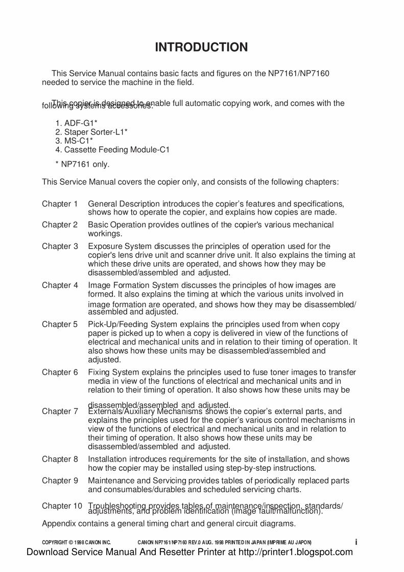
INTRODUCTION
This Service Manual contains basic facts and figures on the NP7161/NP7160needed to service the machine in the field.
This copier is designed to enable full automatic copying work, and comes with thefollowing systems accessories:
1. ADF-G1*2. Staper Sorter-L1*3. MS-C1*4. Cassette Feeding Module-C1
* NP7161 only.
This Service Manual covers the copier only, and consists of the following chapters:
Chapter 1 General Description introduces the copier’s features and specifications,shows how to operate the copier, and explains how copies are made.
Chapter 2 Basic Operation provides outlines of the copier's various mechanicalworkings.
Chapter 3 Exposure System discusses the principles of operation used for thecopier's lens drive unit and scanner drive unit. It also explains the timing atwhich these drive units are operated, and shows how they may bedisassembled/assembled and adjusted.
Chapter 4 Image Formation System discusses the principles of how images areformed. It also explains the timing at which the various units involved in
image formation are operated, and shows how they may be disassembled/ assembled and adjusted.
Chapter 5 Pick-Up/Feeding System explains the principles used from when copypaper is picked up to when a copy is delivered in view of the functions ofelectrical and mechanical units and in relation to their timing of operation. Italso shows how these units may be disassembled/assembled andadjusted.
Chapter 6 Fixing System explains the principles used to fuse toner images to transfermedia in view of the functions of electrical and mechanical units and inrelation to their timing of operation. It also shows how these units may be
disassembled/assembled and adjusted.Chapter 7 Externals/Auxiliary Mechanisms shows the copier’s external parts, and
explains the principles used for the copier’s various control mechanisms inview of the functions of electrical and mechanical units and in relation totheir timing of operation. It also shows how these units may bedisassembled/assembled and adjusted.
Chapter 8 Installation introduces requirements for the site of installation, and showshow the copier may be installed using step-by-step instructions.
Chapter 9 Maintenance and Servicing provides tables of periodically replaced partsand consumables/durables and scheduled servicing charts.
Chapter 10 Troubleshooting provides tables of maintenance/inspection, standards/ adjustments, and problem identification (image fault/malfunction).
Appendix contains a general timing chart and general circuit diagrams.
Download Service Manual And Resetter Printer at http://printer1.blogspot.com
7/16/2019 Canon Np7161-Np7160 Copier Sm
http://slidepdf.com/reader/full/canon-np7161-np7160-copier-sm 6/345
COPYRIGHT © 1998 CANON INC. CANON NP7161/NP7160 REV.0 AUG. 1998 PRINTED IN JAPAN (IMPRIME AU JAPON)ii
The following rules apply throughout this Service Manual:
1. Each chapter contains sections explaining the purpose of specific functions
and the relationship between electrical and mechanical systems with referenceto the timing of operation.
In the diagrams, represents the path of mechanical drive—where asignal name accompanies the symbol , the arrow indicates thedirection of the electric signal.
The expression “turn on the power” means flipping on the power switch,closing the front door, and closing the delivery unit door, which results insupplying the machine with power.
2. In the digital circuits, ‘1’ is used to indicate that the voltage level of a givensignal is “High,” while ‘0’ is used to indicate “Low.” (The voltage value,
however, differs from circuit to circuit.)
In practically all cases, the internal mechanisms of a microprocessor cannot bechecked in the field. Therefore, the operations of the microprocessors used inthe machines are not discussed: they are explained in terms of from sensors tothe input of the DC controller PCB and from the output of the DC controllerPCB to the loads.
The descriptions in this Service Manual are subject to change without notice forproduct improvement or other purposes, and major changes will be communicated inthe form of Service Information bulletins.
All service persons are expected to have a good understanding of the contents of thisService Manual and all relevant Service Information bulletins and be able to identify andisolate faults in the machine.
Download Service Manual And Resetter Printer at http://printer1.blogspot.com
7/16/2019 Canon Np7161-Np7160 Copier Sm
http://slidepdf.com/reader/full/canon-np7161-np7160-copier-sm 7/345
COPYRIGHT © 1998 CANON INC. CANON NP7161/NP7160 REV.0 AUG. 1998 PRINTED IN JAPAN (IMPRIME AU JAPON) iii
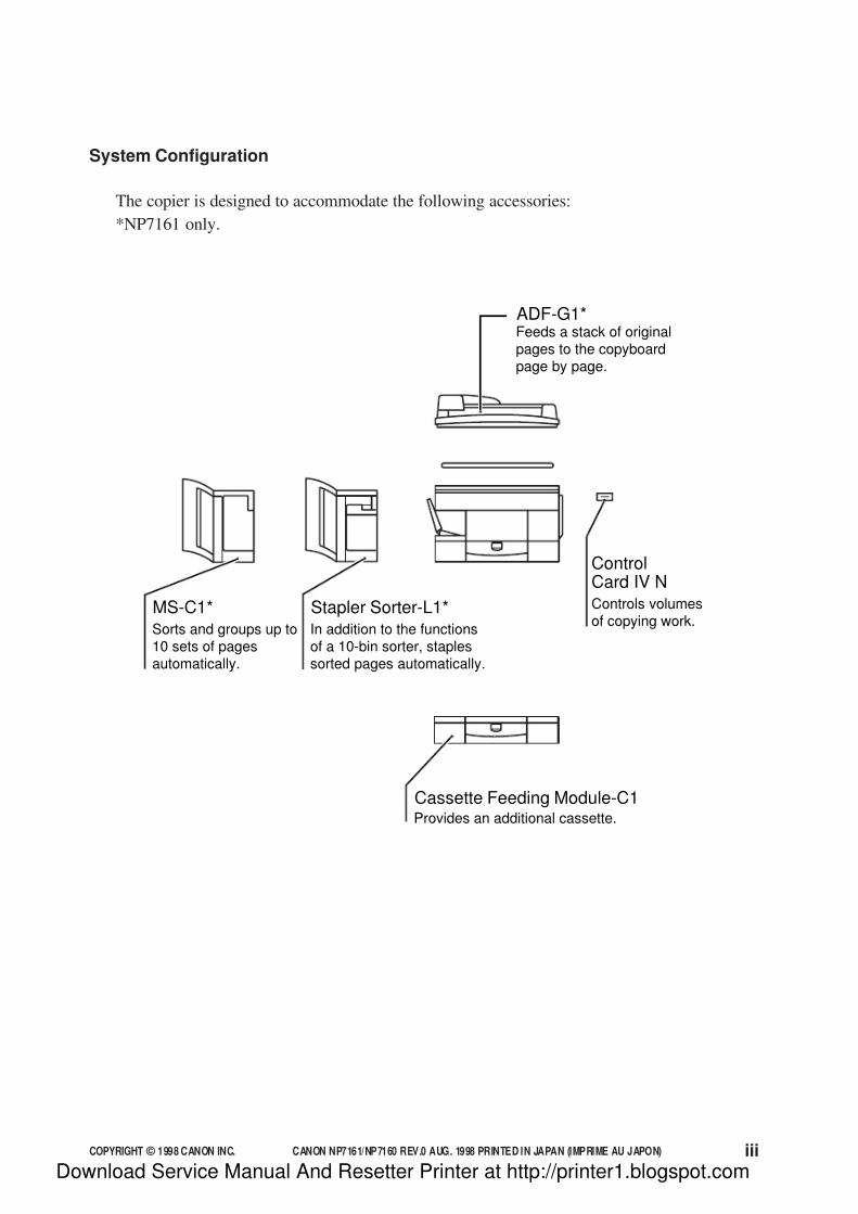
System Configuration
The copier is designed to accommodate the following accessories:
*NP7161 only.
ADF-G1*
ControlCard IV N
Feeds a stack of originalpages to the copyboardpage by page.
Stapler Sorter-L1*
In addition to the functionsof a 10-bin sorter, staplessorted pages automatically.
Cassette Feeding Module-C1Provides an additional cassette.
Controls volumesof copying work.
MS-C1*
Sorts and groups up to10 sets of pagesautomatically.
Download Service Manual And Resetter Printer at http://printer1.blogspot.com

7/16/2019 Canon Np7161-Np7160 Copier Sm
http://slidepdf.com/reader/full/canon-np7161-np7160-copier-sm 8/345
COPYRIGHT © 1998 CANON INC. CANON NP7161/NP7160 REV.0 AUG. 1998 PRINTED IN JAPAN (IMPRIME AU JAPON)iv
Download Service Manual And Resetter Printer at http://printer1.blogspot.com
7/16/2019 Canon Np7161-Np7160 Copier Sm
http://slidepdf.com/reader/full/canon-np7161-np7160-copier-sm 9/345
COPYRIGHT © 1998 CANON INC. CANON NP7161/NP7160 REV.0 AUG. 1998 PRINTED IN JAPAN (IMPRIME AU JAPON) v
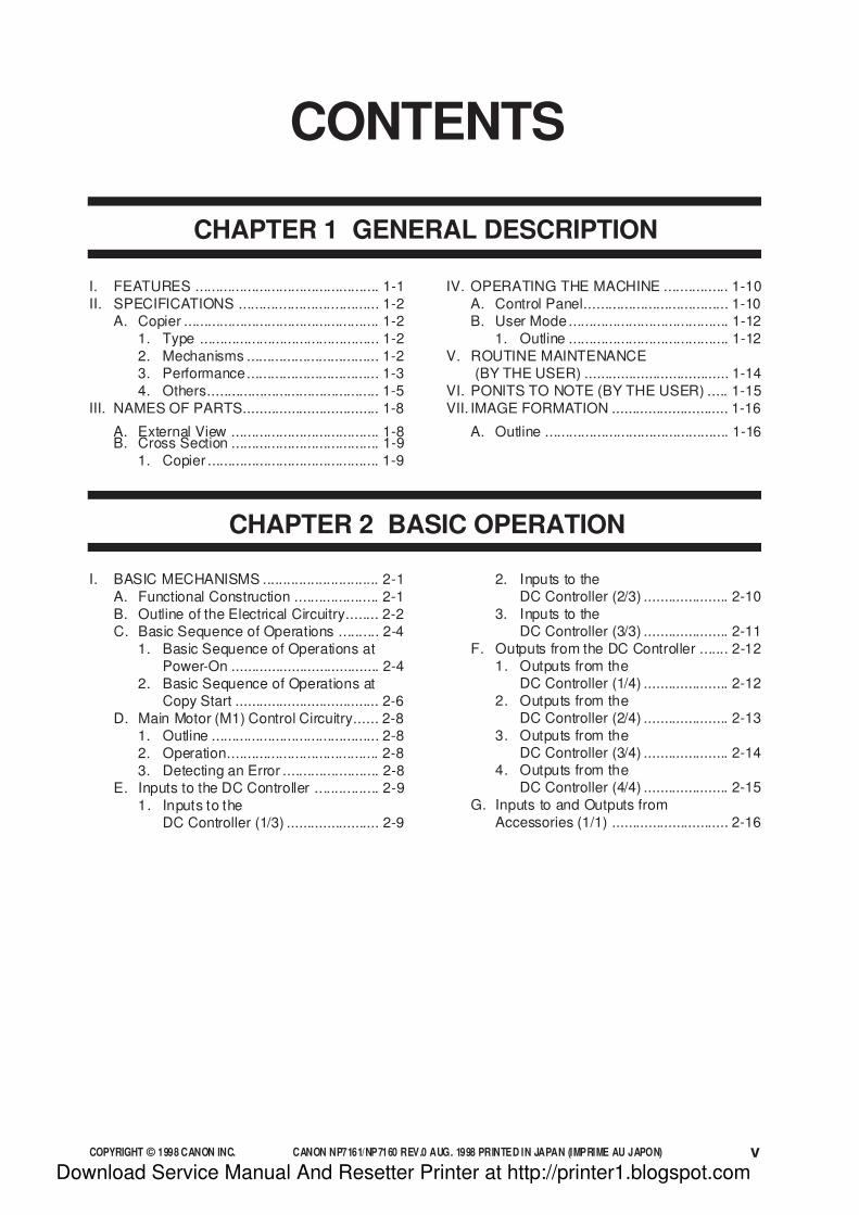
CONTENTS
CHAPTER 1 GENERAL DESCRIPTION
I. FEATURES .............................................. 1-1
II. SPECIFICATIONS ................................... 1-2A. Copier ................................................. 1-2
1. Type ............................................. 1-2
2. Mechanisms ................................. 1-23. Performance................................. 1-3
4. Others........................................... 1-5
III. NAMES OF PARTS.................................. 1-8
A. External View ..................................... 1-8B. Cross Section ..................................... 1-9
1. Copier ........................................... 1-9
IV. OPERATING THE MACHINE ................ 1-10
A. Control Panel.................................... 1-10B. User Mode ........................................ 1-12
1. Outline ........................................ 1-12
V. ROUTINE MAINTENANCE(BY THE USER) .................................... 1-14
VI. PONITS TO NOTE (BY THE USER) ..... 1-15
VII. IMAGE FORMATION ............................. 1-16
A. Outline .............................................. 1-16
CHAPTER 2 BASIC OPERATION
I. BASIC MECHANISMS ............................. 2-1
A. Functional Construction ..................... 2-1
B. Outline of the Electrical Circuitry........ 2-2C. Basic Sequence of Operations .......... 2-4
1. Basic Sequence of Operations atPower-On ..................................... 2-4
2. Basic Sequence of Operations atCopy Start .................................... 2-6
D. Main Motor (M1) Control Circuitry...... 2-81. Outline .......................................... 2-8
2. Operation...................................... 2-8
3. Detecting an Error ........................ 2-8E. Inputs to the DC Controller ................ 2-9
1. Inputs to theDC Controller (1/3) ....................... 2-9
2. Inputs to theDC Controller (2/3) ..................... 2-10
3. Inputs to theDC Controller (3/3) ..................... 2-11
F. Outputs from the DC Controller ....... 2-121. Outputs from the
DC Controller (1/4) ..................... 2-12
2. Outputs from theDC Controller (2/4) ..................... 2-13
3. Outputs from theDC Controller (3/4) ..................... 2-14
4. Outputs from theDC Controller (4/4) ..................... 2-15
G. Inputs to and Outputs from
Accessories (1/1) ............................. 2-16
Download Service Manual And Resetter Printer at http://printer1.blogspot.com

7/16/2019 Canon Np7161-Np7160 Copier Sm
http://slidepdf.com/reader/full/canon-np7161-np7160-copier-sm 10/345
COPYRIGHT © 1998 CANON INC. CANON NP7161/NP7160 REV.0 AUG. 1998 PRINTED IN JAPAN (IMPRIME AU JAPON)vi
CHAPTER 3 EXPOSURE SYSTEM
I. OUTLINE OF OPERATION ..................... 3-1
A. Changing the Reproduction Ratio ...... 3-1
II. LENS DRIVE SYSTEM ............................ 3-3A. Driving the Lens ................................. 3-3
1. Outline .......................................... 3-3
2. Motor Control Circuit .................... 3-43. Moving the Lens ........................... 3-5
III. SCANNER DRIVE SYSTEM.................... 3-6
A. Outline ................................................ 3-6B. Scanner Motor Control Circuit ........... 3-7
C. Relationship between ScannerSensor and Signals ............................ 3-7
D. Basic Sequence of Operations
(scanner) ........................................... 3-8
E. Scanner Movement inPage Separation Mode ...................... 3-9
IV. OTHERS................................................. 3-10A. Detecting the Original Size .............. 3-10
1. Outline ........................................ 3-10
2. Detection of the Original Size
by the ADF ................................. 3-10V. DISASSEMBLY/ASSEMBLY ................. 3-11
A. Scanner Drive Assembly .................. 3-12
1. Removing the Scanner Motor .... 3-12
2. Removing the Scanner DriveCable .......................................... 3-13
3. Routing the Scanner DriveCable .......................................... 3-15
4. Adjusting the Positionof the Mirror ................................ 3-16
5. Adjusting the Tensionof the Scanner Drive Cable........ 3-17
B. Lens Drive Assembly ....................... 3-181. Removing the Lens DriveMotor .......................................... 3-18
2. Removing the Mirror Motor ........ 3-19
CHAPTER 4 IMAGE FORMATION SYSTEM
I. OUTLINE OF THE PROCESSES ............ 4-1
A. Outline ................................................ 4-1
B. Basic Sequence of Operations(image formation system) .................. 4-2
C. Controlling the Intensity of theScanning Lamp .................................. 4-3
1. Outline .......................................... 4-3
2. Operation...................................... 4-4
3. Protection Mechanisms ............... 4-5D. Controlling the Primary/Transfer Bias .. 4-6
1. Outline .......................................... 4-6
2. Turning On/Off the Primary/ Transfer Bias ................................ 4-6
E. Controlling the Developing/SeparationStatic Eliminator Bias ......................... 4-7
1. Outline .......................................... 4-72. Turning On/Off the Developing
DC Bias ........................................ 4-8
3. Turning On/Off the DevelopingAC Bias/Separation EliminatorBias .............................................. 4-9
4. Controlling the DevelopingDC Bias to a Specific Voltageto Suit Copy Density .................. 4-10
F. Controlling the Blank Exposure Lamp ... 4-121. Outline ........................................ 4-12
2. Turning On the Blank Exposure
Lamp in Reduce Mode ............... 4-133. Turning On the Blank Exposure
Lamp in Direct/Enlarge Mode .... 4-13
4. Turning On the Blank ExposureLamp in Multifeeder Mode ......... 4-13
II. DEVELOPING ASSEMBLY/DRUMCLEANER ASSEMBLY.......................... 4-14
A. Outline .............................................. 4-14
B. Detecting and Controllingthe Level of Toner ............................ 4-16
C. Monitoring the Waste TonerFeeding Screw ................................. 4-17
D. Monitoring the Waste Toner Box ..... 4-18E. Control by the Cleaner Thermistor... 4-20
1. Copying Speed DownSequence ................................... 4-20
F. Auto Density Adjustment (AE) ......... 4-21
1. Outline ........................................ 4-21
2. Measuring the Densityof the Original ............................. 4-21
III. DISASSEMBLY/ASSEMBLY ................. 4-23
A. Scanning Lamp Assembly ............... 4-241. Removing the Scanning Lamp .. 4-24
2. Mounting the Scanning Lamp .... 4-25
3. Removing the Thermal Fuse ..... 4-25
B. Exposure Assembly ......................... 4-261. Removing the Pre-Exposure/
Blank Exposure LampAssembly .................................... 4-26
2. Removing the Dust-Proofing
Glass .......................................... 4-263. Cleaning the No. 6 Mirror........... 4-27
C. Drum Unit ......................................... 4-28
Download Service Manual And Resetter Printer at http://printer1.blogspot.com

7/16/2019 Canon Np7161-Np7160 Copier Sm
http://slidepdf.com/reader/full/canon-np7161-np7160-copier-sm 11/345
COPYRIGHT © 1998 CANON INC. CANON NP7161/NP7160 REV.0 AUG. 1998 PRINTED IN JAPAN (IMPRIME AU JAPON) vii
1. Removing the Drum Unit ........... 4-28
2. Cleaning the PhotosensitiveDrum........................................... 4-29
3. Removing the CleanerThermistor .................................. 4-29
D. Primary Charging Assembly ............ 4-30
1. Removing the Primary
Charging Assembly .................... 4-30E. Transfer Charging Assembly ........... 4-31
1. Removing the TransferCharging Assembly .................... 4-31
F. Charging Wire .................................. 4-32
1. Outline ........................................ 4-32
2. Stringing the Charging Wires..... 4-32
3. Adjusting the Height of theCharging Wires .......................... 4-36
G. Developing Assembly....................... 4-37
1. Removing the DevelopingAssembly .................................... 4-37
2. Removing the DevelopingBlade .......................................... 4-37
3. Removing the DevelopingCylinder ...................................... 4-38
CHAPTER 5 PICK-UP/FEEDING SYSTEM
I. OUTLINE OF OPERATION ..................... 5-1
II. PICK-UP FROM THE CASSETTE .......... 5-2A. Pick-Up Operation .............................. 5-2
B. Sequence of Operations(pick-up/feeding) ................................ 5-3
C. Operation of the Cassette Lifter ......... 5-4D. Detecting the Size of the Cassette .... 5-6
1. Outline .......................................... 5-6
2. Detecting the Cassette Size ........ 5-7III. PICK-UP FROM THE MULTIFEEDER .... 5-8
A. Pick-Up Operation .............................. 5-8
B. Detecting the Size of Paperin the Multifeeder ................................ 5-9
C. Sequence of Operations(pick-up from multifeeder) ................ 5-10IV. CONTROLLING THE REGISTRATION
CLUTCH ................................................. 5-11
V. DETECTING JAMS ................................ 5-12
A. Outline .............................................. 5-12B. Sequence of Operations
(jam detection).................................. 5-13
1. Registration Delay Jam.............. 5-13
2. Registration Stationary Jam....... 5-133. Delivery Delay Jam .................... 5-14
4. Delivery Stationary Jam ............. 5-14
VI. DISASSEMBLY/ASSEMBLY ................. 5-15
A. Pick-Up Assembly ............................ 5-161. Removing the Pick-Up Roller..... 5-16
2. Mounting the Pick-Up Roller ...... 5-16
3. Removing the Pick-Up DriveAssembly .................................... 5-17
4. Removing the Pick-UpAssembly .................................... 5-17
5. Removing the Feed Roller ......... 5-18
6. Removing the Separation Roller .. 5-18
7. Mounting the Separation Roller ... 5-19
B. Multifeeder Assembly ....................... 5-201. Removing the Multifeeder Tray.... 5-20
2. Removing the MultifeederAssembly .................................... 5-20
3. Removing the Multifeeder
Pick-Up Roller ............................ 5-214. Removing the Separation Pad..... 5-21
5. Adjusting the Pressure of theSeparation Pad .......................... 5-22
C. Registration Roller Assembly ........... 5-231. Removing the Registration
Roller Assembly ......................... 5-23
D. Cassette Assembly .......................... 5-24
1. Removing the Cassette SizeSwitch ......................................... 5-24
2. Changing the Cassette Size(AB/INCH) .................................. 5-25
3. Adjusting the Left/Right
Registration ................................ 5-26
Download Service Manual And Resetter Printer at http://printer1.blogspot.com

7/16/2019 Canon Np7161-Np7160 Copier Sm
http://slidepdf.com/reader/full/canon-np7161-np7160-copier-sm 12/345
COPYRIGHT © 1998 CANON INC. CANON NP7161/NP7160 REV.0 AUG. 1998 PRINTED IN JAPAN (IMPRIME AU JAPON)viii
CHAPTER 6 FIXING SYSTEM
I. OUTLINE OF OPERATION ..................... 6-1
A. Outline ................................................ 6-1
B. Controlling the Fixing Temperature ... 6-2C. Error Detection Circuit ........................ 6-5
1. Outline .......................................... 6-5
2. Surface Temperature of theFixing Upper Roller ...................... 6-6
3. Activation of theFixing Heater (H1) ........................ 6-6
II. DISASSEMBLY/ASSEMBLY ................... 6-7
A. Fixing Assembly ................................. 6-81. Construction ................................. 6-8
2. Locking Mechanism ..................... 6-8
3. Removing the Fixing Assembly ... 6-8
4. Removing the Fixing Heater ...... 6-105. Removing the Thermal Switch
Assembly .................................... 6-11
6. Removing the Main Thermistor ... 6-12
7. Removing the Sub Thermistor ... 6-12
8. Removing the Fixing UpperRoller .......................................... 6-13
9. Removing the Fixing LowerRoller .......................................... 6-14
10. Removing the Heat DischargeRoller .......................................... 6-14
11. Adjusting the Height of the
Fixing Inlet Guide ....................... 6-1412. Adjusting the Nip ........................ 6-15
B. Delivery Assembly............................ 6-161. Removing the Upper
Separation Claw ......................... 6-16
2. Removing the LowerSeparation Claw ......................... 6-16
3. Removing the Delivery Roller .... 6-17
CHAPTER 7 EXTERNALS/AUXILIARY MECHANISMS
1. Removing the CopyboardGlass .......................................... 7-14
D. Fans.................................................. 7-15
1. Removing the Scanner
Cooling Fan ................................ 7-152. Removing the Exhaust Fan ....... 7-16
3. Remove the Ozone Filter ........... 7-17
E. Counter Assembly ............................ 7-18
1. Removing the CounterAssembly .................................... 7-18
F. Main Motor Assembly....................... 7-18
1. Removing the Main MotorAssembly .................................... 7-18
G. DC Controller PCB ........................... 7-19
1. Removing theDC Controller PCB ..................... 7-19
2. Points to Note When Replacingthe DC Controller PCB............... 7-19
H. Removing the Power Supply PCB ... 7-201. Removing the
Power Supply PCB .................... 7-20
I. Removing the High-VoltagePower Supply PCB........................... 7-20
1. Removing the High-VoltagePower Supply PCB .................... 7-20
J. Lamp Regulator PCB ....................... 7-21
1. Removing the LampRegulator PCB ........................... 7-21
I. FANS ........................................................ 7-1
II. POWER SUPPLY..................................... 7-4
A. Outline of Power Supply .................... 7-4
B. Power Supply Circuitry....................... 7-5
1. AC Power Supply ......................... 7-52. DC Power Supply......................... 7-53. Mirror Heater, Cassette/
Drum Heater, and Accessory
Cassette Heater ........................... 7-64. ADF and Sorter ............................ 7-6
C. Protection Mechanisms of thePower Supply Circuitry ....................... 7-7
III. DISASSEMBLY/ASSEMBLY ................... 7-8
A. External Covers.................................. 7-9
1. Removing the Right Door .......... 7-10
2. Removing the Upper
Right Cover ................................ 7-103. Removing the UpperLeft Cover................................... 7-11
4. Removing the DeliveryLower Cover ............................... 7-11
5. Removing the DeliveryUpper Cover ............................... 7-11
6. Removing the LowerInside Cover ............................... 7-12
B. Control Panel.................................... 7-13
1. Removing the Control Panel ...... 7-13C. Copyboard Glass ............................. 7-14
Download Service Manual And Resetter Printer at http://printer1.blogspot.com

7/16/2019 Canon Np7161-Np7160 Copier Sm
http://slidepdf.com/reader/full/canon-np7161-np7160-copier-sm 13/345
COPYRIGHT © 1998 CANON INC. CANON NP7161/NP7160 REV.0 AUG. 1998 PRINTED IN JAPAN (IMPRIME AU JAPON) ix
CHAPTER 8 INSTALLATION
I. SELECTING THE SITE ............................ 8-1
II. UNPACKING AND INSTALLATION ........ 8-2
A. Unpacking .......................................... 8-2B. Removing the Metal Fixings............... 8-3
C. Mounting the Drum Unit ..................... 8-4
D. Cleaning the Parts and Making Checks .. 8-6E. Checking the Images/Operations and
User Mode .......................................... 8-8
F. Supplying Toner ............................... 8-10
III. RELOCATING THE MACHINE .............. 8-12
IV. INSTALLING THE CONTROL
CARD IV N ............................................. 8-13
V. INSTALLING THE REMOTEDIAGNOSTIC DEVICE II .......................... 8-14
VI. INSTALLING THE ACCESSORY
COUNTER ................................................ 8-23
VII. INSTALLING THE ACCESSORYHEATER ................................................. 8-25
A. Installing the Heater Switch ............. 8-25
B. Mounting the Cassette/Drum Heater 8-26
C. Installing the Mirror Heater ............... 8-27
CHAPTER 9 MAINTENANCE AND SERVICINGI. PERIODICALLY REPLACED PARTS ..... 9-1
A. Copier ................................................. 9-1
II. CONSUMABLES AND DURABLES ........ 9-2
A. Copier ................................................. 9-2
III. SCHEDULED SERVICING CHART ........ 9-3
IV. SCHEDULED SERVICING TABLE ......... 9-5A. Copier ................................................. 9-5
CHAPTER 10 TROUBLESHOOTING
2. Changing the Cassette Size(AB/INCH) ................................ 10-14E. Fixing System................................. 10-16
1. Adjusting the Height of theFixing Assembly Inlet Guide .... 10-16
2. Adjusting the Pressure ofthe Lower Roller (nip)............... 10-16
F. Electrical System............................ 10-18
1. Obtaining Optimum Exposure ... 10-18
2. AE Adjustment ......................... 10-19
3. After Replacing theDC Controller PCB ................... 10-22
4. Checking the Photointerrupters .... 10-23
III. IMAGE FAULTS ................................... 10-25
A. Initial Checks .................................. 10-251. Checking the Site Environment .... 10-25
2. Checking the Originals ............. 10-25
3. Checking the CopyboardCover and Copyboard Glass ... 10-25
4. Checking the ChargingAssembly .................................. 10-26
5. Checking the DevelopingAssembly .................................. 10-26
6. Checking the Paper ................. 10-26
7. Checking the Periodically
Replaced Parts......................... 10-268. Others....................................... 10-26
I. GUIDE TO TROUBLESHOOTINGTABLES .................................................. 10-1
A. Image Adjustment Basic Procedure 10-3
B. Points to Note for Scheduled Servicing . 10-4II. STANDARDS AND ADJUSTMENTS .... 10-5
A. Mechanical ....................................... 10-5
1. Leading Edge Non-ImageWidth (blank exposure lampoff timing).................................... 10-5
2. Image Leading Edge Margin(registration on timing) ............... 10-5
3. Left/Right Registration(cassette).................................... 10-6
B. Exposure System ............................. 10-7
1. Routing the Scanner DriveCable .......................................... 10-7
2. Adjusting the Positionof the Mirror ................................ 10-8
3. Adjusting the Tensionof the Scanner Drive Cable........ 10-9
C. Image Formation System ............... 10-101. Outline ...................................... 10-10
2. Stringing the Charging Wires... 10-10
3. Adjusting the Height of theCharging Wires ........................ 10-13
D. Pick-Up/Feeding System ............... 10-141. Adjusting the Pressure
of the Separation Pad .............. 10-14
Download Service Manual And Resetter Printer at http://printer1.blogspot.com
7/16/2019 Canon Np7161-Np7160 Copier Sm
http://slidepdf.com/reader/full/canon-np7161-np7160-copier-sm 14/345
COPYRIGHT © 1998 CANON INC. CANON NP7161/NP7160 REV.0 AUG. 1998 PRINTED IN JAPAN (IMPRIME AU JAPON)x
B. Image Fault Samples ..................... 10-28
C. Troubleshooting Image Faults ....... 10-29
1. The copy is too light.(halftone area only) .................. 10-29
2. The copy is too light.(including solid black area) ...... 10-30
3. The copy is too light.
(entirely, considerably) ............. 10-304. The copy has uneven density.
(front side dark) ........................ 10-31
5. The copy has uneven density.(front side light) ........................ 10-31
6. The copy is foggy. (overall)...... 10-32
7. The copy is foggy. (vertical) ..... 10-33
8. The copy has black lines.(vertical, fuzzy, thick) ............... 10-33
9. The copy has black lines.(vertical, thin)............................ 10-33
10. The copy has white spots.
(vertical).................................... 10-3411. The copy has white lines.
(vertical).................................... 10-34
12. The copy has white spots.(vertical).................................... 10-35
13. The back of the copy is soiled. .. 10-36
14. The copy has faulty fixing. ....... 10-3715. The copy has a displaced
leading edge............................. 10-38
16. The copy has a displacedleading edge............................. 10-38
17. The copy has a displaced
leading edge............................. 10-3818. The copy has a blurred image. .. 10-39
19. The copy is foggy.(horizontally) ............................. 10-39
20. The copy has poor sharpness. .. 10-40
21. The copy is blank. .................... 10-41
22. The copy is solid black. ............ 10-41
IV. TROUBLESHOOTINGMALFUNCTIONS ................................. 10-42
A. Copier ............................................. 10-42
1. E000 ......................................... 10-42
2. E001 ......................................... 10-433. E002/E003 ............................... 10-44
4. E004 ......................................... 10-455. E010 ......................................... 10-456. E013 ......................................... 10-46
7. E030 ......................................... 10-46
8. E031 ......................................... 10-47
9. E202 (The keys on the controlpanel fail to operate.) ............... 10-47
10. E208 ......................................... 10-48
11. E210 ......................................... 10-48
12. E220 ......................................... 10-4913. E261 ......................................... 10-49
14. E710/E711 ............................... 10-49
15. E712 ......................................... 10-5016. E717 ......................................... 10-50
17. E800 ......................................... 10-51
18. E805 ......................................... 10-51
19. E821 ......................................... 10-5120. AC power is absent. ................. 10-52
21. DC power supply is absent. ..... 10-53
22. The scanner fails to move........ 10-5423. The lens fails to move. ............. 10-55
24. The mirror fails to move. .......... 10-5525. The scanning lamp
fails to turn on. .......................... 10-56
26. The pre-exposure lampfails to turn on. .......................... 10-57
27. The blank exposure lampfails to turn on. .......................... 10-57
28. Pick-up fails. (cassette) ............ 10-58
29. Pick-up operation fails.(multifeeder) ............................. 10-59
30. The registration roller failsto rotate. ................................... 10-59
31. The fixing heater fails toturn on. ..................................... 10-60
32. The Add Toner indicatordoes not flash/turn on. ............. 10-60
33. The Add Toner indicator failsto turn off. ................................. 10-61
34. The Waste Toner Box Full indicator fails to flash/turn on. ... 10-61
35. The Waste Toner Box Fullindicator fails to turn off. ........... 10-62
36. The Add Paper indicatorfails to flash. ............................. 10-62
37. The Add Paper indicatorfails to turn off. .......................... 10-63
38. The Jam indicator fails toflash. ......................................... 10-63
39. The Jam indicator fails toturn off. ..................................... 10-64
40. The Set Control Card indicatorfails to turn on. .......................... 10-64
41. The Set Control Card indicatorfails to turn off. .......................... 10-65
V. TROUBLESHOOTING FEEDING
PROBLEMS.......................................... 10-66
A. Copy Jams ..................................... 10-66
1. Pick-Up/Feeding Assembly ...... 10-672. Fixing/Delivery Assembly......... 10-68
B. Faulty Feeding................................ 10-69
1. Double Feeding........................ 10-692. Wrinkles.................................... 10-69
VI. ARRANGEMENT AND FUNCTIONSOF ELECTRICAL PARTS .................... 10-70
A. Sensors and Switches ................... 10-70B. Motors, Fans, Clutches,
and Solenoids................................. 10-72
C. Heaters, Lamps, and Others .......... 10-74
D. PCBs .............................................. 10-76
E. Variable Resistors, Light-EmittingDiodes, and Check Pins by PCB ... 10-77
Download Service Manual And Resetter Printer at http://printer1.blogspot.com
7/16/2019 Canon Np7161-Np7160 Copier Sm
http://slidepdf.com/reader/full/canon-np7161-np7160-copier-sm 15/345
COPYRIGHT © 1998 CANON INC. CANON NP7161/NP7160 REV.0 AUG. 1998 PRINTED IN JAPAN (IMPRIME AU JAPON) xi
1. DC Controller PCB ................... 10-77
2. Power Supply PCB .................. 10-80
3. Lamp Regulator PCB ............... 10-804. High-Voltage Power Supply
PCB .......................................... 10-81
VII. SERVICE MODE .................................. 10-82
A. Outline ............................................ 10-82
B. Using Service Mode ....................... 10-821. Starting Service Mode.............. 10-82
2. Selecting Service Mode ........... 10-82
C. Using Adjust Mode andFunction Mode................................ 10-83
D. Display Mode [1] ............................ 10-84
E. I/O Display Mode [2] ....................... 10-88
F. Adjust Mode [3] .............................. 10-92G. Function Mode [4] .......................... 10-94
H. Option Mode [5] .............................. 10-95
I. Counter Mode [6] ........................... 10-97J. Application Mode [7]....................... 10-98
VIII. SELF DIAGNOSIS .............................. 10-99A. Copier ............................................. 10-99
B. ADF .............................................. 10-103C. Sorter ............................................ 10-104
D. Cassette Feeding Module ............ 10-104
A. GENERAL TIMING CHART............... A-1
B. SIGNALS AND ABBREVIATIONS ....A-2C. GENERAL CIRCUIT DIAGRAM ........ A-5
APPENDIX
D. SPECIAL TOOLS LIST ...................... A-7
E. SOLVENTS AND OILS ......................A-8
Download Service Manual And Resetter Printer at http://printer1.blogspot.com

7/16/2019 Canon Np7161-Np7160 Copier Sm
http://slidepdf.com/reader/full/canon-np7161-np7160-copier-sm 16/345
Download Service Manual And Resetter Printer at http://printer1.blogspot.com

7/16/2019 Canon Np7161-Np7160 Copier Sm
http://slidepdf.com/reader/full/canon-np7161-np7160-copier-sm 17/345
COPYRIGHT © 1998 CANON INC. CANON NP7161/NP7160 REV.0 AUG. 1998 PRINTED IN JAPAN (IMPRIME AU JAPON)
I. FEATURES .............................................. 1-1
II. SPECIFICATIONS ................................... 1-2
A. Copier ................................................. 1-2
III. NAMES OF PARTS.................................. 1-8
A. External View ..................................... 1-8B. Cross Section ..................................... 1-9
IV. OPERATING THE MACHINE ................ 1-10
A. Control Panel.................................... 1-10B. User Mode ........................................ 1-12
V. ROUTINE MAINTENANCE
(BY THE USER) .................................... 1-14
VI. PONITS TO NOTE (BY THE USER) ..... 1-15VII. IMAGE FORMATION ............................. 1-16
A. Outline .............................................. 1-16
This chapter introduces the copier’s features and specifications, shows how to operate the copier, and
explains how copies are made.
CHAPTER 1
GENERAL DESCRIPTION
Download Service Manual And Resetter Printer at http://printer1.blogspot.com

7/16/2019 Canon Np7161-Np7160 Copier Sm
http://slidepdf.com/reader/full/canon-np7161-np7160-copier-sm 18/345
Download Service Manual And Resetter Printer at http://printer1.blogspot.com

7/16/2019 Canon Np7161-Np7160 Copier Sm
http://slidepdf.com/reader/full/canon-np7161-np7160-copier-sm 19/345
COPYRIGHT © 1998 CANON INC. CANON NP7160/NP7161 REV.0 AUG. 1998 PRINTED IN JAPAN (IMPRIME AU JAPON) 1–1
CHAPTER 1 GENERAL DESCRIPTION
I. FEATURES
1. The copier is designed light in weight (about 42 kg), and compact in size (566 mm wide,
541mm deep).
2. The copier turns out as many as 16 copies each minute (A4/LTR).
3. The addition of the Cassette Feeding Module-C1 (accessory) enables a source of paper
capable of holding a maximum of 1,050 sheets.
4. The density may be adjusted to 33 different shades, or in automatic mode (AE).
5. The use of a photo mode promises faithful reproduction of halftone.
6. The use of an auto power-off function promises power-saving operation.
Download Service Manual And Resetter Printer at http://printer1.blogspot.com

7/16/2019 Canon Np7161-Np7160 Copier Sm
http://slidepdf.com/reader/full/canon-np7161-np7160-copier-sm 20/345
1–2 COPYRIGHT © 1998 CANON INC. CANON NP7160/NP7161 REV.0 AUG. 1998 PRINTED IN JAPAN (IMPRIME AU JAPON)
CHAPTER 1 GENERAL DESCRIPTION
II. SPECIFICATIONS
A. Copier
1. Type
2. Mechanisms
Body
Copyboard
Light source
Lens
Photosensitive material
Desktop
Fixed
Halogen lamp (120V:200W/230V:220W)
Lens array
OPC (30 dia.)
Copying
Charging
Exposure
Copy density adjustment
Development
Auto
Manual
Transfer
Separation
Cleaning
Fixing
Indirect electrostatic
Corona
Slit (moving light source)
Auto or manual
Dry (toner projection)
Front cassette (1 pc.)
Multifeeder (5 mm deep approx.; about 50 sheets of 80 g/m2 paper)
Corona
Curvature + static eliminator
Blade
Heat roller (1000 W for 120V model; 1050 W for 230V model)
Pick-up
Download Service Manual And Resetter Printer at http://printer1.blogspot.com

7/16/2019 Canon Np7161-Np7160 Copier Sm
http://slidepdf.com/reader/full/canon-np7161-np7160-copier-sm 21/345
COPYRIGHT © 1998 CANON INC. CANON NP7160/NP7161 REV.0 AUG. 1998 PRINTED IN JAPAN (IMPRIME AU JAPON) 1–3
CHAPTER 1 GENERAL DESCRIPTION
3. Performance
Original type
Maximum original size
Direct
Reduce I
Reduce II
Reduce III
Reduce IV
Enlarge I
Enlarge II
Enlarge III
Enlarge IV
Zoom
Wait time
First copy
Continuous copying
Copy size
Cassette
Multifeeder
Sheet, book, 3-D object (2 kg max.)
A3/279 × 432 mm (11"×17")
1:1.000
1:0.5000
1:0.707
1:0.0816
1:0.0865
1:1.154
1:1.224
1:1.414
1:2.000
1:0.500 to 2.000 (in 1% increments)
30 sec or less (at 20°C room temperature)
5.8 sec or less (A4, Direct, non-AE, cassette)
999 sheets max.
A3/279×432 mm (11"×17") max. B5R/STMTR min.
• Plain paper (64 to 80 g/m2)
A3, B4, A4R, A4, B5R,B5, 279 × 432 mm (11"×17"), LTRR, LTR, LGL
• Colored paper (recommended by Canon)
B4, A4
• Plain paper (64 to 80 g/m2)
A3, B4, A4R, A4, B5R, B5, A5, 279X432 mm (11"×17"), LTRR,
LTR, LGL, STMTR
• Tracing paper (SM-1, GNT80)A3, B4, A4R, A4, B5R, B5, A5
• Transparency (recommended by Canon)
A4/LTR
• Colored paper (recommended by Canon)*
B4, A4
• Label paper (recommended by Canon)
A4/LTR
• Heavy paper (up to 128 g/m2)
Reproduction
ratio
Copy paper
type
*May be used, but may not feed properly.
Download Service Manual And Resetter Printer at http://printer1.blogspot.com
7/16/2019 Canon Np7161-Np7160 Copier Sm
http://slidepdf.com/reader/full/canon-np7161-np7160-copier-sm 22/345
1–4 COPYRIGHT © 1998 CANON INC. CANON NP7160/NP7161 REV.0 AUG. 1998 PRINTED IN JAPAN (IMPRIME AU JAPON)
CHAPTER 1 GENERAL DESCRIPTION
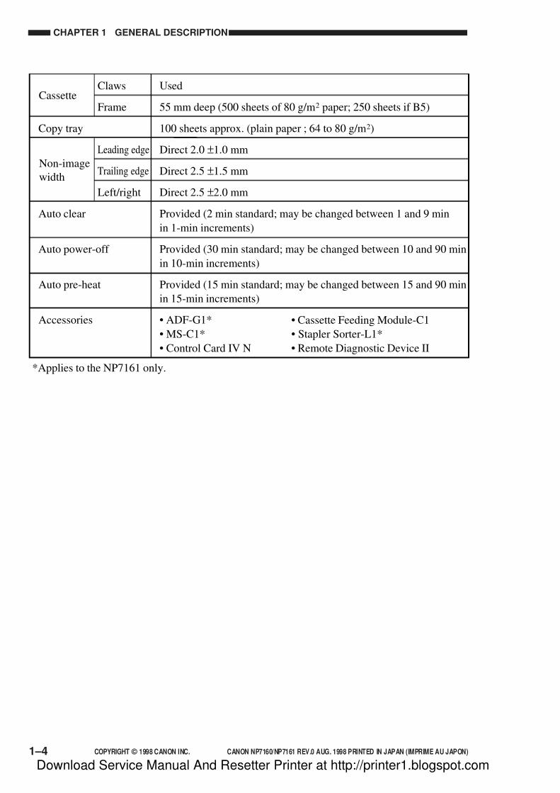
Claws
Frame
Copy tray
Leading edge
Trailing edge
Left/right
Auto clear
Auto power-off
Auto pre-heat
Accessories
Used
55 mm deep (500 sheets of 80 g/m2 paper; 250 sheets if B5)
100 sheets approx. (plain paper ; 64 to 80 g/m2)
Direct 2.0 ±1.0 mm
Direct 2.5 ±1.5 mm
Direct 2.5 ±2.0 mm
Provided (2 min standard; may be changed between 1 and 9 min
in 1-min increments)
Provided (30 min standard; may be changed between 10 and 90 min
in 10-min increments)
Provided (15 min standard; may be changed between 15 and 90 min
in 15-min increments)
• ADF-G1*
• MS-C1*
• Control Card IV N
*Applies to the NP7161 only.
Cassette
Non-image
width
• Cassette Feeding Module-C1
• Stapler Sorter-L1*
• Remote Diagnostic Device II
Download Service Manual And Resetter Printer at http://printer1.blogspot.com
7/16/2019 Canon Np7161-Np7160 Copier Sm
http://slidepdf.com/reader/full/canon-np7161-np7160-copier-sm 23/345
COPYRIGHT © 1998 CANON INC. CANON NP7160/NP7161 REV.0 AUG. 1998 PRINTED IN JAPAN (IMPRIME AU JAPON) 1–5
CHAPTER 1 GENERAL DESCRIPTION
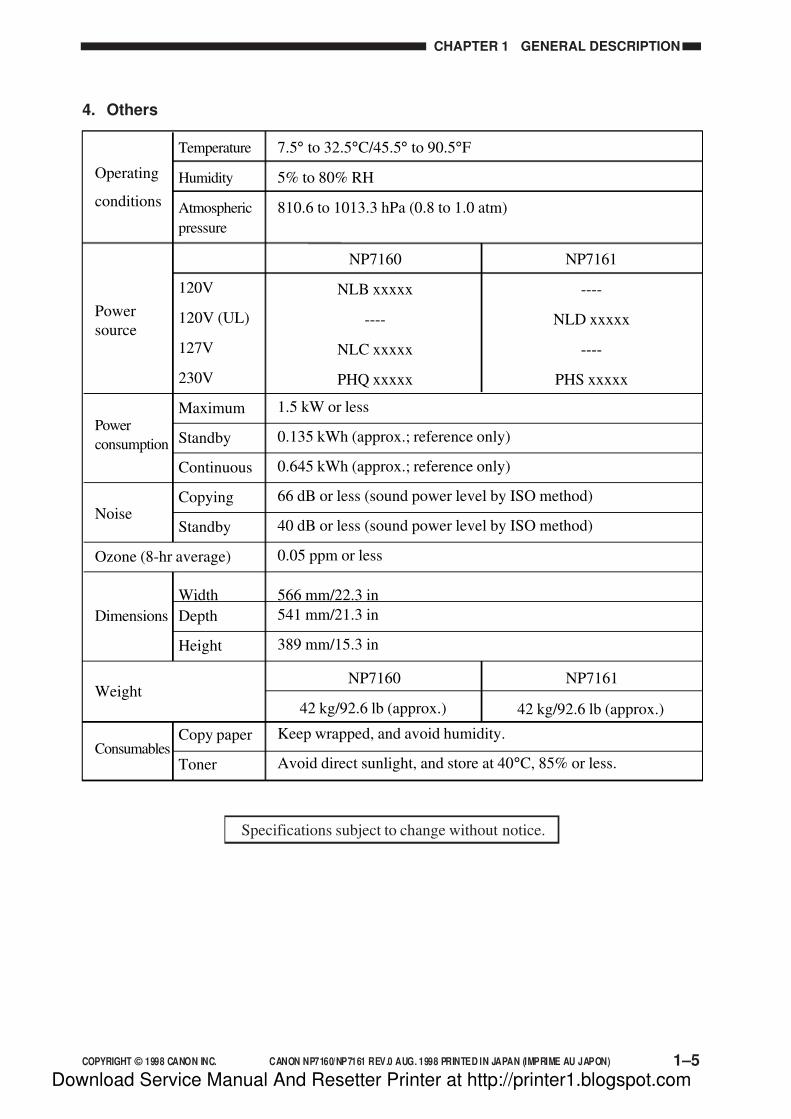
4. Others
Specifications subject to change without notice.
Temperature
Humidity
Atmospheric
pressure
120V
120V (UL)
127V
230V
Maximum
Standby
Continuous
Copying
Standby
Ozone (8-hr average)
Width
Depth
Height
Copy paper
Toner
7.5° to 32.5°C/45.5° to 90.5°F
5% to 80% RH
810.6 to 1013.3 hPa (0.8 to 1.0 atm)
1.5 kW or less
0.135 kWh (approx.; reference only)
0.645 kWh (approx.; reference only)
66 dB or less (sound power level by ISO method)
40 dB or less (sound power level by ISO method)
0.05 ppm or less
566 mm/22.3 in
541 mm/21.3 in
389 mm/15.3 in
Keep wrapped, and avoid humidity.
Avoid direct sunlight, and store at 40°C, 85% or less.
NP7160
NLB xxxxx
----
NLC xxxxx
PHQ xxxxx
NP7161
----
NLD xxxxx
----
PHS xxxxx
Operating
conditions
Power
source
Power
consumption
Noise
Weight
Consumables
Dimensions
NP7161
42 kg/92.6 lb (approx.)
NP7160
42 kg/92.6 lb (approx.)
Download Service Manual And Resetter Printer at http://printer1.blogspot.com
7/16/2019 Canon Np7161-Np7160 Copier Sm
http://slidepdf.com/reader/full/canon-np7161-np7160-copier-sm 24/345
1–6 COPYRIGHT © 1998 CANON INC. CANON NP7160/NP7161 REV.0 AUG. 1998 PRINTED IN JAPAN (IMPRIME AU JAPON)
CHAPTER 1 GENERAL DESCRIPTION
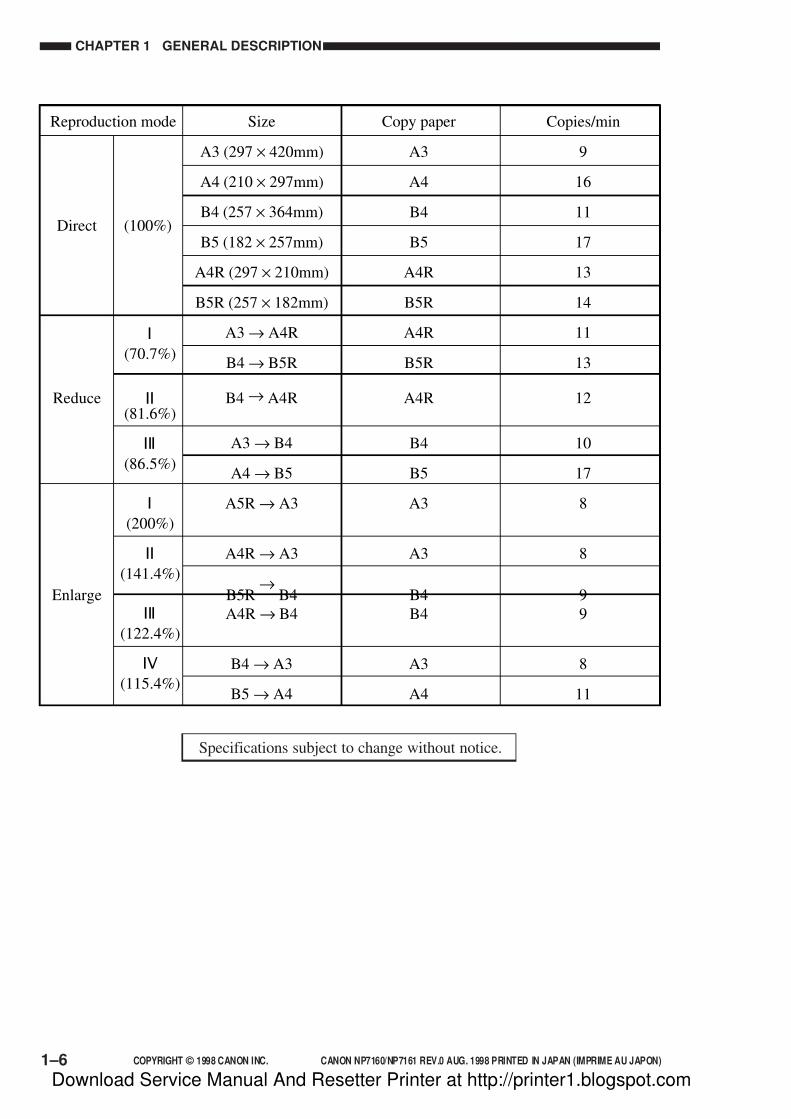
Size
A3 (297 × 420mm)
A4 (210 × 297mm)
B4 (257 × 364mm)
B5 (182 × 257mm)
A4R (297 × 210mm)
B5R (257 × 182mm)
A3 → A4R
B4 → B5R
B4 → A4R
A3 → B4
A4 → B5
A5R → A3
A4R → A3
B5R→
B4
A4R → B4
B4 → A3
B5 → A4
Reproduction mode Copy paper
A3
A4
B4
B5
A4R
B5R
A4R
B5R
A4R
B4
B5
A3
A3
B4
B4
A3
A4
Copies/min
9
16
11
17
13
14
11
13
12
10
17
8
8
9
9
8
11
Direct
Reduce
Enlarge
(100%)
I
(70.7%)
II
(81.6%)
III
(86.5%)
I
(200%)
II
(141.4%)
III
(122.4%)
IV
(115.4%)
Specifications subject to change without notice.
Download Service Manual And Resetter Printer at http://printer1.blogspot.com

7/16/2019 Canon Np7161-Np7160 Copier Sm
http://slidepdf.com/reader/full/canon-np7161-np7160-copier-sm 25/345
COPYRIGHT © 1998 CANON INC. CANON NP7160/NP7161 REV.0 AUG. 1998 PRINTED IN JAPAN (IMPRIME AU JAPON) 1–7
CHAPTER 1 GENERAL DESCRIPTION
Size
11" × 17" (279 × 432mm)
LTR (297 × 216mm)
LGL (216 × 356mm)
LTRR (216 × 297mm)
Reproduction mode Copy paper
11" × 17"
LTR
LGL
LTRR
LTRR
LGL
LTRR
11" × 17"
11" × 17"
11" × 17"
Copies/min
9
16
11
13
12
11
12
8
8
8
Direct
Reduce
Enlarge
(100%)
I
(64.7%)
II
(73.3%)
III
(78.6%)
I
(200%)
II
(129.4%)
III
(121.4%)
11" × 17" → LTRR
11" × 17" → LGL
LGL → LTRR
STMTR → 11" × 17"
LTRR → 11" × 17"
LGL → 11" × 17"
Specifications subject to change without notice.
Download Service Manual And Resetter Printer at http://printer1.blogspot.com

7/16/2019 Canon Np7161-Np7160 Copier Sm
http://slidepdf.com/reader/full/canon-np7161-np7160-copier-sm 26/345
1–8 COPYRIGHT © 1998 CANON INC. CANON NP7160/NP7161 REV.0 AUG. 1998 PRINTED IN JAPAN (IMPRIME AU JAPON)
CHAPTER 1 GENERAL DESCRIPTION
III. NAMES OF PARTS
A. External View
Figure 1-301
Figure 1-302
[4] Lower delivery cover
[5] Front fixing cover
[6] Inside cover
[7] Open/close lever
[8] Lower inside cover
[9] Static eliminator
[1] Copy tray
[2] Upper left cover
[3] Upper delivery cover
[1] [2] [3] [4] [5] [6] [7] [8]
[9]
[1] [2] [3] [7][4] [5] [6]
[8][9][10][11][12]
[5] Upper right cover
[6] Upper rear cover
[7] Multifeeder
[8] Waste toner box
[9] Right door
[10] Right cover
[11] Front door
[12] Cassette
[1] Control panel
[2] Copyboard glass
[3] Copyboard cover
[4] Power switch
Download Service Manual And Resetter Printer at http://printer1.blogspot.com
7/16/2019 Canon Np7161-Np7160 Copier Sm
http://slidepdf.com/reader/full/canon-np7161-np7160-copier-sm 27/345
COPYRIGHT © 1998 CANON INC. CANON NP7160/NP7161 REV.0 AUG. 1998 PRINTED IN JAPAN (IMPRIME AU JAPON) 1–9
CHAPTER 1 GENERAL DESCRIPTION
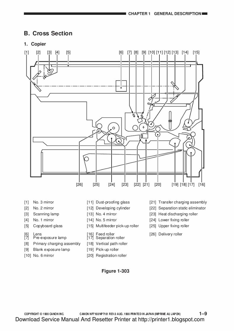
B. Cross Section
1. Copier
[1] [2] [3] [4] [5] [6] [10] [11] [13][7] [8] [9] [14][12] [15]
[16][17][19][24][25][26] [20][21][22][23] [18]
[21] Transfer charging assembly
[22] Separation static eliminator
[23] Heat discharging roller
[24] Lower fixing roller
[25] Upper fixing roller
[26] Delivery roller
[11] Dust-proofing glass
[12] Developing cylinder
[13] No. 4 mirror
[14] No. 5 mirror
[15] Multifeeder pick-up roller
[16] Feed roller[17] Separation roller
[18] Vertical path roller
[19] Pick-up roller
[20] Registration roller
[1] No. 3 mirror
[2] No. 2 mirror
[3] Scanning lamp
[4] No. 1 mirror
[5] Copyboard glass
[6] Lens[7] Pre-exposure lamp
[8] Primary charging assembly
[9] Blank exposure lamp
[10] No. 6 mirror
Figure 1-303
Download Service Manual And Resetter Printer at http://printer1.blogspot.com
7/16/2019 Canon Np7161-Np7160 Copier Sm
http://slidepdf.com/reader/full/canon-np7161-np7160-copier-sm 28/345
1–10 COPYRIGHT © 1998 CANON INC. CANON NP7160/NP7161 REV.0 AUG. 1998 PRINTED IN JAPAN (IMPRIME AU JAPON)
CHAPTER 1 GENERAL DESCRIPTION
IV. OPERATING THE MACHINE
A. Control Panel
ID
2 31
5 64
8 97
0 C
Reset
AdditionalFunctions
Interrupt
Clear
Start
Stop
Energy Saver
Auto Zoom %
Zoom
Paper Select
Auto Paper
A3/1117
A4/LTR
A4/LTR
B4/LGL
B5 U1
R
B5 U2R
123
Reduce 1 : 1 Enlarge
Max. 200%
A4/ LTR A3 B5 B4
A4/LTR B4
B4 A3 B5 A4/ LTR
1 : 1
A3 B4 A4/ LTR B5
B 4 A 4/ LT R
A3 B5A4/LTR B4
Min. 50%
Fit ImageImage Combination
Two-page SeparationPhoto
A
Sort
Staple-Sort
Group
ON/OFF
[1] [2] [3] [5][4] [9][8][7][6] [16][15][14][13][12][11][10] [17] [18] 1[9] [21]
[22] [23] [24][25] [26][27] [28]
[20]
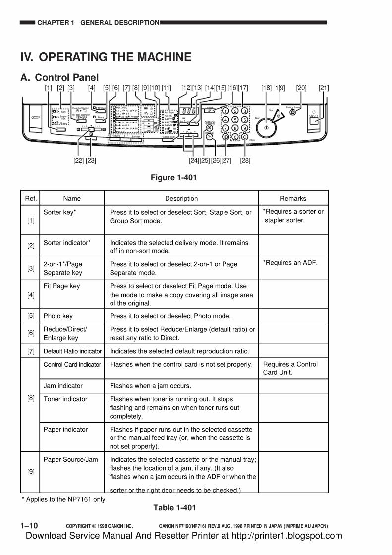
Ref. Name
[1]
[2]
[3]
[4]
[5]
[6]
[7]
[8]
[9]
Description Remarks
*Requires a sorter or
stapler sorter.
*Requires an ADF.
Requires a Control
Card Unit.
* Applies to the NP7161 only
Sorter key*
Sorter indicator*
2-on-1*/Page
Separate key
Fit Page key
Photo key
Reduce/Direct/
Enlarge key
Default Ratio indicator
Control Card indicator
Jam indicator
Toner indicator
Paper indicator
Paper Source/Jam
Press it to select or deselect Sort, Staple Sort, or
Group Sort mode.
Indicates the selected delivery mode. It remains
off in non-sort mode.
Press it to select or deselect 2-on-1 or Page
Separate mode.
Press to select or deselect Fit Page mode. Use
the mode to make a copy covering all image area
of the original.
Press it to select or deselect Photo mode.
Press it to select Reduce/Enlarge (default ratio) or
reset any ratio to Direct.
Indicates the selected default reproduction ratio.
Flashes when the control card is not set properly.
Flashes when a jam occurs.
Flashes when toner is running out. It stops
flashing and remains on when toner runs out
completely.
Flashes if paper runs out in the selected cassette
or the manual feed tray (or, when the cassette is
not set properly).
Indicates the selected cassette or the manual tray;
flashes the location of a jam, if any. (It also
flashes when a jam occurs in the ADF or when the
sorter or the right door needs to be checked.)
Figure 1-401
Table 1-401
Download Service Manual And Resetter Printer at http://printer1.blogspot.com

7/16/2019 Canon Np7161-Np7160 Copier Sm
http://slidepdf.com/reader/full/canon-np7161-np7160-copier-sm 29/345
COPYRIGHT © 1998 CANON INC. CANON NP7160/NP7161 REV.0 AUG. 1998 PRINTED IN JAPAN (IMPRIME AU JAPON) 1–11
CHAPTER 1 GENERAL DESCRIPTION
Ref. Name
[15]
[16]
[17]
[18]
[19]
[20]
[21]
[22]
[23]
[24]
[25]
[26]
[27]
[28]
* Applies to the NP7161 only
Description Remarks
[10]
[11]
[12]
[13]
[14]
*Requires an ADF.
*Requires an ADF.
Flashes when the waste toner box needs to be
replaced. When the case becomes full, it stops
flashing and remains on.
Indicates the size of the paper in the cassette
selected by the Paper Select key.
Press it to select Auto Paper Select*, Cassette, or
Manual Feed Tray mode.
Indicates the copy count/ratio and the selected
user mode.
Use it to select or deselect Auto Ratio mode, in
which the best reproduction ratio is automatically
selected to suit the original and the selected
paper.
Press it to indicate the selected reproduction ratio.
Use it to reset the current copy mode to default.
Use it to set a copy count or to enter a numeric value.
Press it to start copying.
Press it to stop continuous copying.
Press it to select or deselect power save mode.
Press it to turn on or off the power.
Slide it to adjust the copy density manually.
Press it to select or deselect AE (auto density
adjustment) mode.
Press it to select a reproduction ratio (50% to
200%) in 1% increments. Hold it down to
increase/decrease the ratio continuously.
Press it to set or change user mode settings.
Press it to stop an ongoing copying run to make a
copy of a different original.
Press it after entering an appropriate ID number.
Press it also after entering a number for ID
registration.
Press it to reset the copy count to 1 or to clear any
wrong input when making settings.
Location indicator
Paper Size indicator
Paper Select key
Copy Count/Ratio
indicator
Auto Ratio key*
% key
Reset key
Keypad
Start key
Stop key
Power Save key
Power switch
Copy Density
lever
AE key
Zoom key
User Mode key
Interrupt key
ID key
Clear key
Table 1-402
Download Service Manual And Resetter Printer at http://printer1.blogspot.com
7/16/2019 Canon Np7161-Np7160 Copier Sm
http://slidepdf.com/reader/full/canon-np7161-np7160-copier-sm 30/345
1–12 COPYRIGHT © 1998 CANON INC. CANON NP7160/NP7161 REV.0 AUG. 1998 PRINTED IN JAPAN (IMPRIME AU JAPON)
CHAPTER 1 GENERAL DESCRIPTION
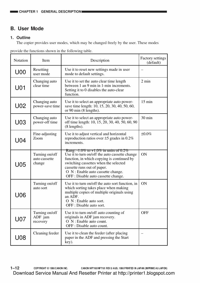
B. User Mode
1. Outline
The copier provides user modes, which may be changed freely by the user. These modes
provide the functions shown in the following table.
Notation
Resettinguser mode
Changing autoclear time
Changing autopower-save time
Changing autopower-off time
Fine-adjustingZoom
Turning on/off auto cassettechange
Turning on/off auto sort
Turning on/off ADF jamrecovery
Cleaning feeder
–
2 min
15 min
30 min
±0.0%
ON
ON
OFF
–
DescriptionItemFactory settings
(default)
U00
U01
U02
U03
U04
U05
U06
U07
U08
Use it to reset new settings made in usermode to default settings.
Use it to set the auto clear time lengthbetween 1 an 9 min in 1-min increments.Setting it to 0 disables the auto-clearfunction.
Use it to select an appropriate auto power-save time length: 10, 15, 20, 30, 40, 50, 60,or 90 min (8 lengths).
Use it to select an appropriate auto power-off time length: 10, 15, 20, 30, 40, 50, 60, 90(8 lengths).
Use it to adjust vertical and horizontalreproduction ratios over ±5 grades in 0.2%increments.
Rang: -1.0% to +1.0% in units of 0.2%Use it to turn on/off the auto cassette changefunction, in which copying is continued byswitching cassettes when the selectedcassette runs out of paper.O N : Enable auto cassette change.OFF : Disable auto cassette change.
Use it to turn on/off the auto sort function, inwhich sorting takes place when makingmultiple copies of multiple originals usingan ADF.O N : Enable auto sort.OFF : Disable auto sort.
Use it to turn on/off auto counting of originals in ADF jam recovery.O N : Enable auto count.OFF : Disable auto count.
Use it to clean the feeder (after placingpaper in the ADF and pressing the Startkey).
Download Service Manual And Resetter Printer at http://printer1.blogspot.com

7/16/2019 Canon Np7161-Np7160 Copier Sm
http://slidepdf.com/reader/full/canon-np7161-np7160-copier-sm 31/345
COPYRIGHT © 1998 CANON INC. CANON NP7160/NP7161 REV.0 AUG. 1998 PRINTED IN JAPAN (IMPRIME AU JAPON) 1–13
CHAPTER 1 GENERAL DESCRIPTION
Changing PageFit mode (ratio)
Changing PageFit mode(centering)
Changing PageFit mode(non-image width)
Correctingdensity
Setting specialpaper mode
Drum cleaningmode
93%
ON
OFF
0
0
OFF
U09
U10
U11
U12
U13
U14*
Use it to change the reproduction ratio usedin Page Fit mode between 90% and 99% in
1% increments.
Use it to turn on/off the centering function inFit Page mode.O N : Enable centering.OFF : Disable centering.
Use it to turn on/off the non-image widthfunction in Page Fit mode.O N : Enable (create non-image width).OFF : Disable (do not create non-image
width).
Use it to select an appropriate standard value(F5) for manual density adjustment between-17 and +6 (24 grades).
Use it to select an appropriate fixingtemperature control mode for special paperwhen pick-up is from the multifeeder.0: Standard1: Rough surface paper (against poor fixing)2: Tracing paper (against high-temperature
offset)
Use it to turn ON/OFF the drum cleaningfunction.To remove dirt from the surface of thephotosensitive drum, toner is deposited onthe surface after copying operation and thecleaning blade is used to collect the tonertogether with the dirt. (In addition, LSTR isextended by 6.5 sec)O N : Enable drum cleaning.OFF : Disable drum cleaning.
* If the drum cleaning settings in service mode No. 519 is turned ON.
Notation DescriptionItemFactory settings
(default)
Download Service Manual And Resetter Printer at http://printer1.blogspot.com
7/16/2019 Canon Np7161-Np7160 Copier Sm
http://slidepdf.com/reader/full/canon-np7161-np7160-copier-sm 32/345
1–14 COPYRIGHT © 1998 CANON INC. CANON NP7160/NP7161 REV.0 AUG. 1998 PRINTED IN JAPAN (IMPRIME AU JAPON)
CHAPTER 1 GENERAL DESCRIPTION
V. ROUTINE MAINTENANCE (BY THE USER)
Instruct the user to clean the following parts at least once a week.
1. Copyboard Glass
Wipe with a moist cloth (moistened with water or mild detergent solution); then, dry wipe.
2. Copyboard Cover
Wipe it with a moist cloth (moistened with water or mild detergent solution); then, dry wipe.
3. Primary Charging Assembly
Pull out and then push in the wire cleaner several times to clean the charging wire.
4. Transfer Charging Assembly
Pull out and then push in the wire cleaner several times to clean the charging wire.
5. Static Eliminator
If separation jams occur frequently, clean the static eliminator using the special brush.
(Cleaning need not be as often as every week.)6. Waste Toner Box
If the Waste Toner Box indicator on the control panel flashes or turns on, replace the waste
toner box.
Download Service Manual And Resetter Printer at http://printer1.blogspot.com

7/16/2019 Canon Np7161-Np7160 Copier Sm
http://slidepdf.com/reader/full/canon-np7161-np7160-copier-sm 33/345
COPYRIGHT © 1998 CANON INC. CANON NP7160/NP7161 REV.0 AUG. 1998 PRINTED IN JAPAN (IMPRIME AU JAPON) 1–15
CHAPTER 1 GENERAL DESCRIPTION
VI. POINTS TO NOTE (BY THE USER)
• Toner Cartridge
Instruct the user to dispose of any used (empty) toner cartridge according to governmental
guidelines.
• Waste Toner Box
Instruct the user to keep any waste toner box for collection during a servicing visit.
Caution:
Do not dispose of the toner cartridge or the waste toner box into fire. Toner can catch
fire, causing implosion or explosion.
Download Service Manual And Resetter Printer at http://printer1.blogspot.com

7/16/2019 Canon Np7161-Np7160 Copier Sm
http://slidepdf.com/reader/full/canon-np7161-np7160-copier-sm 34/345
1–16 COPYRIGHT © 1998 CANON INC. CANON NP7160/NP7161 REV.0 AUG. 1998 PRINTED IN JAPAN (IMPRIME AU JAPON)
CHAPTER 1 GENERAL DESCRIPTION
VII.IMAGE FORMATION
A. Outline
The copier is constructed as shown in Figure 1-701.
Copyboard glass
Scanninglamp
Lens
Pre-exposure
lamp
Fixing
assembly
Primary chargingassembly
Blanking exposurelamp
Staticeliminator
Transfer chargingassembly
Pick-up(multifeeder)
Pick-up(cassette)
Developingassembly
Figure 1-701
Download Service Manual And Resetter Printer at http://printer1.blogspot.com

7/16/2019 Canon Np7161-Np7160 Copier Sm
http://slidepdf.com/reader/full/canon-np7161-np7160-copier-sm 35/345
COPYRIGHT © 1998 CANON INC. CANON NP7160/NP7161 REV.0 AUG. 1998 PRINTED IN JAPAN (IMPRIME AU JAPON) 1–17
CHAPTER 1 GENERAL DESCRIPTION
The copier's image formation processes consist of the following eight steps:
Step 1 Pre-exposure
Step 2 Primary charging (negative DC)
Step 3 Image exposure
Step 4 Development (AC + negative DC)
Step 5 Transfer (negative DC)
Step 6 Separation (curvature + static eliminator)
Step 7 Fixing
Step 8 Drum cleaning
2. Primary charging
1. Pre-exposure
4. Development
Delivery 7. Fixing 6. Separation
8. Drum cleaning
3. Image exposure
Flow of copy paper
Rotation of drum
Multifeeder5. Transfer
Cassette
Registration
Static latent image formation block
Figure 1-702
Download Service Manual And Resetter Printer at http://printer1.blogspot.com

7/16/2019 Canon Np7161-Np7160 Copier Sm
http://slidepdf.com/reader/full/canon-np7161-np7160-copier-sm 36/345
Download Service Manual And Resetter Printer at http://printer1.blogspot.com
7/16/2019 Canon Np7161-Np7160 Copier Sm
http://slidepdf.com/reader/full/canon-np7161-np7160-copier-sm 37/345
COPYRIGHT © 1998 CANON INC. CANON NP7161/NP7160 REV.0 AUG. 1998 PRINTED IN JAPAN (IMPRIME AU JAPON)
CHAPTER 2
BASIC OPERATION
I. BASIC MECHANISMS ............................. 2-1A. Functional Construction ..................... 2-1
B. Outline of the Electrical Circuitry........ 2-2C. Basic Sequence of Operations .......... 2-4
D. Main Motor (M1) Control Circuitry...... 2-8
E. Inputs to the DC Controller ................ 2-9F. Outputs from the DC Controller ....... 2-12
G. Inputs to and Outputs fromAccessories (1/1) ............................. 2-16
This chapter provides outlines of the copier’s various mechanical workings.
Process speed 105 mm/s
Download Service Manual And Resetter Printer at http://printer1.blogspot.com

7/16/2019 Canon Np7161-Np7160 Copier Sm
http://slidepdf.com/reader/full/canon-np7161-np7160-copier-sm 38/345
Download Service Manual And Resetter Printer at http://printer1.blogspot.com
7/16/2019 Canon Np7161-Np7160 Copier Sm
http://slidepdf.com/reader/full/canon-np7161-np7160-copier-sm 39/345
COPYRIGHT © 1998 CANON INC. CANON NP7161/NP7160 REV.0 AUG. 1998 PRINTED IN JAPAN (IMPRIME AU JAPON) 2–1
CHAPTER 2 BASIC OPERATION
I. BASIC MECHANISMS
A. Functional Construction
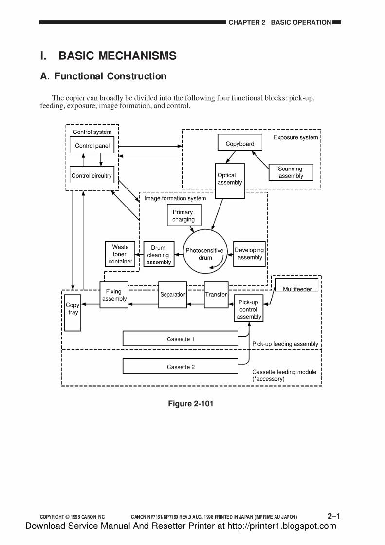
The copier can broadly be divided into the following four functional blocks: pick-up,feeding, exposure, image formation, and control.
Figure 2-101
Control system
Copyboard
Scanning
assembly
Photosensitive
drum
Drum
cleaning
assembly
Waste
toner
container
Pick-up
control
assembly
Multifeeder
Cassette 1Pick-up feeding assembly
Cassette 2Cassette feeding module
(*accessory)
Exposure system
Control panel
Image formation system
Copy
tray
Control circuitry
Fixing
assemblySeparation Transfer
Optical
assembly
Primary
charging
Developing
assembly
Download Service Manual And Resetter Printer at http://printer1.blogspot.com

7/16/2019 Canon Np7161-Np7160 Copier Sm
http://slidepdf.com/reader/full/canon-np7161-np7160-copier-sm 40/345
2–2 COPYRIGHT © 1998 CANON INC. CANON NP7161/NP7160 REV.0 AUG. 1998 PRINTED IN JAPAN (IMPRIME AU JAPON)
CHAPTER 2 BASIC OPERATION
B. Outline of the Electrical Circuitry
The copier's major electrical mechanisms are controlled by the microprocessor on the DC
controller PCB. The ICs on the DC controller PCB are shown below.
IC121 (ROM)
• Controls copying sequence.
JC113 (gate array)
• Controls scanning lamp (LA1) error detection.
• Controls thermistor (TH1, TH2) error detection.
• Controls triac short circuit error detection.
• Controls power at time of error.
• Turns on/off the scanning lamp (LA3).• Controls the I/O port.
IC114 (IPC; NP7161 only)
• Controls communication with the ADF and the sorter.
JC116 (RAM)
• Records settings data (service mode, etc.).
IC117 (RESET IC)
• Resets at power-on.
Figure 2-102 is a block diagram showing the relationship between the copier's major circuits.
Reference:
The NP7161 possesses a communications IC (IPC) on its DC controller PCB. The copier
communicates with the ADF and the sorter using the communications IC on each controller
PCB (IPC communication) and the communications PCB on the DC controller PCB (IPC
communication 2).
Download Service Manual And Resetter Printer at http://printer1.blogspot.com

7/16/2019 Canon Np7161-Np7160 Copier Sm
http://slidepdf.com/reader/full/canon-np7161-np7160-copier-sm 41/345
COPYRIGHT © 1998 CANON INC. CANON NP7161/NP7160 REV.0 AUG. 1998 PRINTED IN JAPAN (IMPRIME AU JAPON) 2–3
CHAPTER 2 BASIC OPERATION
Figure 2-102
<Control> <Loads><Sensors>
SensorsSwitches
Tonersensor
AEsensor
Controlpanel
Thermistors
DC controller PCB
IC119(CPU)
Cassette relayPCB
Motors
Fans
Clutches
Solenoids
Counter
LEDs
Scanninglamp
LampregulatorPCBPower
supplyPCB
Heaters
Chargingassembly
Developingcylinder
HVT
Cassette feedingmodule
SensorsSwitches
ADF controller PCBIPC Micro-
processorADF
SensorsSwitches
Sorter controller PCBStapler sorter
or SorterSensorsSwitches IPC Micro-
processor
IC114(IPC)
IC117(RESET)
IC116(RAM)
IC121(ROM)
IC113(GA)
Download Service Manual And Resetter Printer at http://printer1.blogspot.com

7/16/2019 Canon Np7161-Np7160 Copier Sm
http://slidepdf.com/reader/full/canon-np7161-np7160-copier-sm 42/345
2–4 COPYRIGHT © 1998 CANON INC. CANON NP7161/NP7160 REV.0 AUG. 1998 PRINTED IN JAPAN (IMPRIME AU JAPON)
CHAPTER 2 BASIC OPERATION
C. Basic Sequence of Operations
1. Basic Sequence of Operations at Power-On
Figure 2-103
, ,
Power switchON 160°C120°C
Wait indicator
WMUP WMUPR
(flashing) Green
STBYSequence
Scanner motor (M2)
Scanner home positionsensor (PS1)
Lens motor (M3)
Lens home positionsensor (PS2)
Mirror motor (M4)
Mirror home positionsensor (PS3)
Fixing heater (H1)
Main motor (M1)
Primary charging assembly
Developing DC bias
Developing AC bias
Transfer charging assembly
Pre-exposure lamp (LA2)
Static eliminator
Blank exposure lamp (LA3)
Scanning lamp (LA1)
Download Service Manual And Resetter Printer at http://printer1.blogspot.com

7/16/2019 Canon Np7161-Np7160 Copier Sm
http://slidepdf.com/reader/full/canon-np7161-np7160-copier-sm 43/345
COPYRIGHT © 1998 CANON INC. CANON NP7161/NP7160 REV.0 AUG. 1998 PRINTED IN JAPAN (IMPRIME AU JAPON) 2–5
CHAPTER 2 BASIC OPERATION
WMUP(warm-up)
From when the powerswitch is turned on untilthe surface temperature
of the upper fixing rollerreaches 120˚C.
Waits until the upper fixingroller warms up.
Moves the lens, mirror,and scanner to homeposition.
Period Description Remarks
WMUPR(warm-up rotation)
From when WMUP endsuntil the surface temper-ature of the upper fixingroller reaches 160˚C.
• Evens out the surfacetemperature of the upperfixing roller.
• Stirs the toner inside thedeveloping assembly.
• Discharges copy paper,if any, inside the copier.
Starts copying operationwhen the surfacetemperature of the upperfixing roller reaches 140˚Cif Auto Start has beenselected.
STBY(standby)
From when WMUPR endsuntil the Copy Start key ispressed. Or, from when
LSTR ends until the powerswitch is turned off.
Waits for a press on anoperation key(Start key, etc.).
Turns on Auto Clearif no operation key ispressed (i.e., resets to
standard mode after aspecific period of time).
Table 2-101
Download Service Manual And Resetter Printer at http://printer1.blogspot.com
7/16/2019 Canon Np7161-Np7160 Copier Sm
http://slidepdf.com/reader/full/canon-np7161-np7160-copier-sm 44/345
2–6 COPYRIGHT © 1998 CANON INC. CANON NP7161/NP7160 REV.0 AUG. 1998 PRINTED IN JAPAN (IMPRIME AU JAPON)
CHAPTER 2 BASIC OPERATION
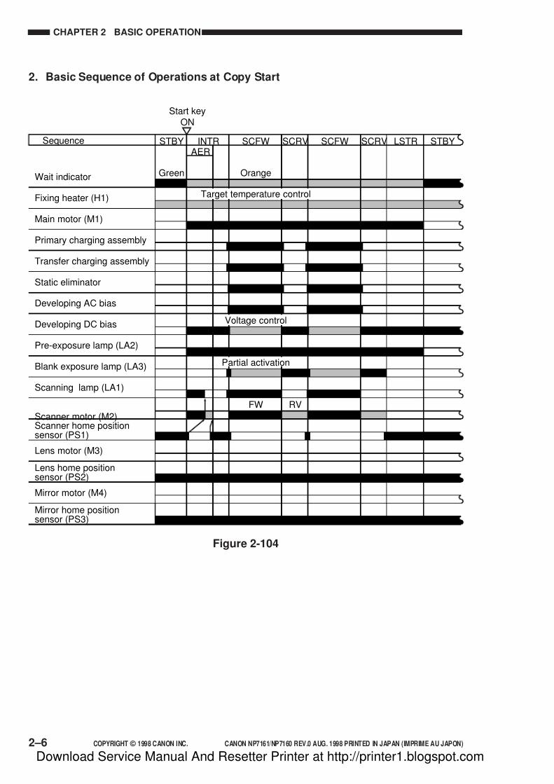
2. Basic Sequence of Operations at Copy Start
Figure 2-104
Start keyON
Wait indicator
STBY
Green Orange
FW RV
STBYLSTRSCRVSCFWSCRVSCFWINTRAER
Sequence
Scanner motor (M2)Scanner home positionsensor (PS1)
Fixing heater (H1)
Main motor (M1)
Primary charging assembly
Developing DC bias
Developing AC bias
Transfer charging assembly
Static eliminator
Pre-exposure lamp (LA2)
Blank exposure lamp (LA3)
Scanning lamp (LA1)
Target temperature control
Voltage control
Partial activation
Lens motor (M3)
Lens home positionsensor (PS2)
Mirror motor (M4)
Mirror home positionsensor (PS3)
Download Service Manual And Resetter Printer at http://printer1.blogspot.com

7/16/2019 Canon Np7161-Np7160 Copier Sm
http://slidepdf.com/reader/full/canon-np7161-np7160-copier-sm 45/345
COPYRIGHT © 1998 CANON INC. CANON NP7161/NP7160 REV.0 AUG. 1998 PRINTED IN JAPAN (IMPRIME AU JAPON) 2–7
CHAPTER 2 BASIC OPERATION
Table 2-102
INTR(initial rotation)
From when the Start keyis pressed until thescanner starts to move
forward.
Stabilizes the drumsensitivity in preparationfor copying operation.
Period Description Remarks
AER(AE rotation)
From when the Start keyis pressed until thescanner finishesmeasuring densuty.
Measures the density ofthe original while thescanner is moving forward.
Used only in AE mode.
SCFW(scanner forward)
While the scanner ismoving forward.
Uses the scanning lamp toshine the original, anddirects the reflected optical
image to the photosensitivedrum by way of mirrorsand lenses.
Generates the registrationsignal, and moves thecopy paper to the transfer
assembly.
SCRV(scanner reverse)
While the scanner ismoving in reverse.
Returns the scanner tohome position inpreparation for the nextcopying operation.
LSTR
(last rotation)
From when SCRV ends
until the main motor stops.
Rids the surface of the
photosensitive drum ofcharges (surface potential)as post-copying operation.
Discharges the last copy.
Download Service Manual And Resetter Printer at http://printer1.blogspot.com
7/16/2019 Canon Np7161-Np7160 Copier Sm
http://slidepdf.com/reader/full/canon-np7161-np7160-copier-sm 46/345
2–8 COPYRIGHT © 1998 CANON INC. CANON NP7161/NP7160 REV.0 AUG. 1998 PRINTED IN JAPAN (IMPRIME AU JAPON)
CHAPTER 2 BASIC OPERATION
D. Main Motor (M1) Control Circuitry
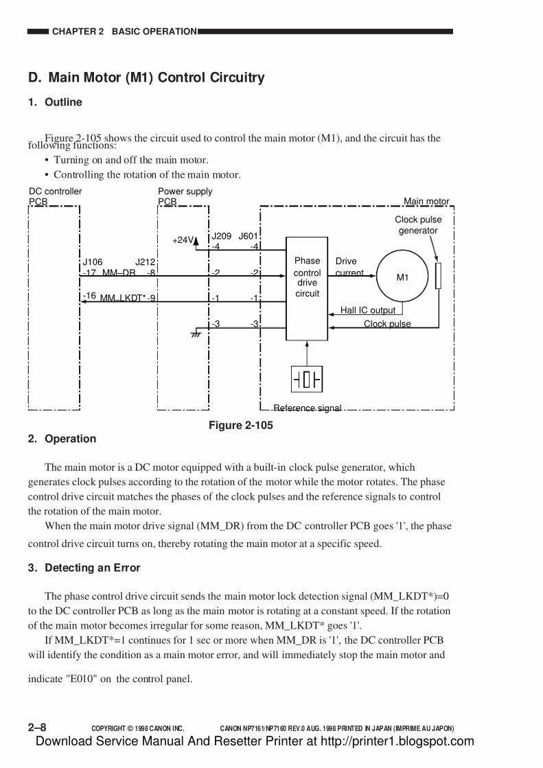
1. Outline
Figure 2-105 shows the circuit used to control the main motor (M1), and the circuit has thefollowing functions:
• Turning on and off the main motor.
• Controlling the rotation of the main motor.
Figure 2-105
2. Operation
The main motor is a DC motor equipped with a built-in clock pulse generator, which
generates clock pulses according to the rotation of the motor while the motor rotates. The phase
control drive circuit matches the phases of the clock pulses and the reference signals to control
the rotation of the main motor.
When the main motor drive signal (MM_DR) from the DC controller PCB goes '1', the phase
control drive circuit turns on, thereby rotating the main motor at a specific speed.
3. Detecting an Error
The phase control drive circuit sends the main motor lock detection signal (MM_LKDT*)=0
to the DC controller PCB as long as the main motor is rotating at a constant speed. If the rotation
of the main motor becomes irregular for some reason, MM_LKDT* goes '1'.
If MM_LKDT*=1 continues for 1 sec or more when MM_DR is '1', the DC controller PCB
will identify the condition as a main motor error, and will immediately stop the main motor and
indicate "E010" on the control panel.
J106-17
-16
Main motor
Drive
current
Hall IC output
DC controllerPCB
J209-4
-2
-1
-3
J212-8MM – DR
MM – LKDT*-9
J601-4
-2
-1
-3
Power supplyPCB
+24V
M1
Phase
controldrivecircuit
Reference signal
Clock pulsegenerator
Clock pulse
Download Service Manual And Resetter Printer at http://printer1.blogspot.com
7/16/2019 Canon Np7161-Np7160 Copier Sm
http://slidepdf.com/reader/full/canon-np7161-np7160-copier-sm 47/345
COPYRIGHT © 1998 CANON INC. CANON NP7161/NP7160 REV.0 AUG. 1998 PRINTED IN JAPAN (IMPRIME AU JAPON) 2–9
CHAPTER 2 BASIC OPERATION
E. Inputs to the DC Controller
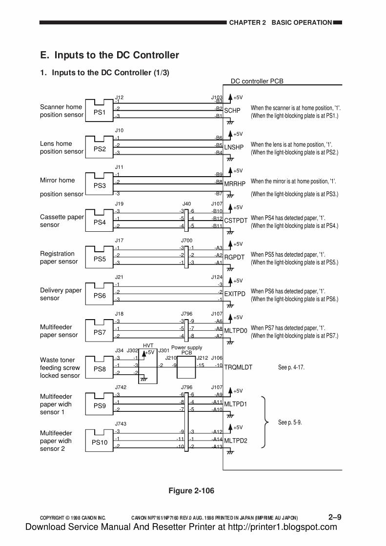
1. Inputs to the DC Controller (1/3)
Figure 2-106
DC controller PCB
+5VJ12-1
-2
-3
J103-B3
-B2
-B1
Scanner homeposition sensor
When the scanner is at home position, '1'.(When the light-blocking plate is at PS1.)
SCHPPS1
+5VJ10
-1
-2
-3
-B6
-B5
-B4
Lens homeposition sensor
When the lens is at home position, '1'.(When the light-blocking plate is at PS2.)
LNSHPPS2
+5VJ11
-1
-2
-3
-B9
-B8
-B7
Mirror home
position sensor
When the mirror is at home position, '1'.
(When the light-blocking plate is at PS3.)
MRRHPPS3
+5V-3
-5
-4
-6
-4
-5
J19
-3
-1
-2
J107
-B10
-B12
-B11
Cassette papersensor
When PS4 has detected paper, '1'.(When the light-blocking plate is at PS4.)
CSTPDT
J40
PS4
+5V-3
-2
-1
-1
-2
-3
J17
-1
-2
-3
-A3
-A2
-A1
Registrationpaper sensor
When PS5 has detected paper, '1'.(When the light-blocking plate is at PS5.)
RGPDT
J700
PS5
+5VJ21
-1
-2
-3
J124
-3
-2
-1
Delivery papersensor
When PS6 has detected paper, '1'.(When the light-blocking plate is at PS6.)
EXITPDPS6
+5V-3
-5
-4
-9
-7
-8
J18
-3
-1
-2
J107
-A6
-A8
-A7
Multifeederpaper sensor
When PS7 has detected paper, '1'.(When the light-blocking plate is at PS7.)
MLTPD0
J796
PS7
+5VJ34
-3
-1
-2
J302
-1
-3
-2
J301
-2
J210
-9
J212
-15
J106
-10Waste tonerfeeding screwlocked sensor
TRQMLDTPS8
+5V-6
-8
-7
-9
-11
-10
-6
-4
-5
-3
-1
-2
J742
-3
-1
-2
J107
-A9
-A11
-A10
-A12
-A14
-A13
Multifeederpaper widhsensor 1
See p. 5-9.
See p. 4-17.
MLTPD1
J796
PS9
+5VJ743
-3
-1
-2
Multifeederpaper widhsensor 2
MLTPD2PS10
Power supplyPCB
HVT
Download Service Manual And Resetter Printer at http://printer1.blogspot.com

7/16/2019 Canon Np7161-Np7160 Copier Sm
http://slidepdf.com/reader/full/canon-np7161-np7160-copier-sm 48/345
2–10 COPYRIGHT © 1998 CANON INC. CANON NP7161/NP7160 REV.0 AUG. 1998 PRINTED IN JAPAN (IMPRIME AU JAPON)
CHAPTER 2 BASIC OPERATION
2. Inputs to the DC Controller (2/3)
Figure 2-107
DC controller PCB
+5VJ48
-3
-1
-2
J107
-B5
-B7
-B6
Right dooropen sensor
RDOPDTPS11
J106
-9Waste toner
sensor
When the waste toner box is identified as
being full or the waste toner box is absent, '1'.
TNFDT
+5VJ102
-B3
-B2
-B1Toner sensor When the level of toner drops below a
specific level, '1'.TNEMPTS1
When the right door is closed, '1'.(When the light-blocking plate is at PS11.)
-5
-7
-6
-3
-1
-2
J797
-1
-3
-2
-3
-1
-2
J47
-3
-2
-1
-1
-2
-3
J720
-3
-2
-1
-3
-2
-1
J721
-1
-2
-3
-3
-2
-1
J15
+5VJ303
-1
-3
-2
J301
-1
J210
-10
J212
-16
Power supplyPCB
HVT
Download Service Manual And Resetter Printer at http://printer1.blogspot.com
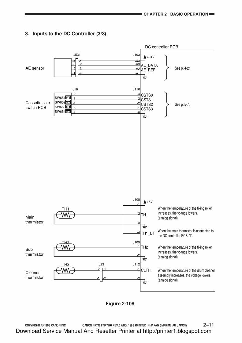
7/16/2019 Canon Np7161-Np7160 Copier Sm
http://slidepdf.com/reader/full/canon-np7161-np7160-copier-sm 49/345
COPYRIGHT © 1998 CANON INC. CANON NP7161/NP7160 REV.0 AUG. 1998 PRINTED IN JAPAN (IMPRIME AU JAPON) 2–11
CHAPTER 2 BASIC OPERATION
3. Inputs to the DC Controller (3/3)
Figure 2-108
DC controller PCB
+24V
+5V
J103
-A4-A3
-A2
-A1
AE sensor See p. 4-21.AE_DATAAE_REF
J16
-2
-3
-4
-5
-1
J110
-4
-3
-2
-1
-5
Cassette sizeswitch PCB
See p. 5-7.CSTS1CSTS2CSTS3
CSTS0
-4-3
-2
-1
-1-2
-3
-4
J531
J108
-1
-2
-3
-4
Mainthermistor
TH1
When the temperature of the fixing rollerincreases, the voltage lowers.(analog signal)
TH1_DTWhen the main thermistor is connected tothe DC controller PCB, '1'.
TH1
J109-1
-2
Subthermistor
TH2 When the temperature of the fixing rollerincreases, the voltage lowers.(analog signal)
TH2
J112
-1
-2
Cleanerthermistor
CLTH When the temperature of the drum cleanerassembly increases, the voltage lowers.(analog signal)
TH3
SW651
SW652
SW653
SW654
-2
-1
-1
-2
J23
Download Service Manual And Resetter Printer at http://printer1.blogspot.com

7/16/2019 Canon Np7161-Np7160 Copier Sm
http://slidepdf.com/reader/full/canon-np7161-np7160-copier-sm 50/345
2–12 COPYRIGHT © 1998 CANON INC. CANON NP7161/NP7160 REV.0 AUG. 1998 PRINTED IN JAPAN (IMPRIME AU JAPON)
CHAPTER 2 BASIC OPERATION
F. Outputs from the DC Controller
1. Outputs from the DC Controller (1/4)
Figure 2-109
DC controller PCB
Cassette/Drumheater (H2)(accessory)
Heater switch(SW1) (accessory)
Cassetteheater (H4)
(accessory)
Mirror heater(H3)(accessory)
Fixing heater(H1)
Power supply PCB
J204
-1
-5
-2
-1
-2
-1
J52
-2
-1
-2
-1
J54
RL
LampregulatorPCB
HVT
Scannimg lamp (LA1)
Thermal fuse (FU1)
-2
-1
-2
-1
J53
J203
-1
-3
-4
-6
J503-1
-2
-3
-4
-5
J211-5
-4
-3
-2
-1
J212
-21
-17
-19
J106
-4
-8
-6
J210
-1
-8
-7
-6
-5
-4
-3
-2
J212
-14
-13
-12
-11
-10
J106
-11
-12
-13
-14
-15
J301
-10
-3
-4
-5
-6
-7
-8
-9
J307
-1
-3
To RL1
J501
-1
-3
-1
-3
-1
-3
J55
-1
-3
-1
-3
J51
J105
-1
-2
-3
-5
-4
J208
-1
-2
-3
-4
-5
+24VGND+5VU+5VRGND
J106
-19
-21
J212
-6
-4HEAT_ERR
See p.6-5.
See p.4-3.
See p.4-6.
HEAT_DR
J106
-22
-23
-24
J212
-3
-2
-1
See p.7-4.
ZRCRSS5V_ONAC_24V_ON
LMPDR
LMP_PWMLMPDT
DV_DC_CNTDV_DC_DRDV_AC_CNTDV_AC_DRHVT_DR
CB2
-1
-2
-1
-2
J201
Thermo switch(TSW1)
ACdriver
DS1
LF
CB1
+24V+24V
+5V
+5V
RL1
To HVT(J307)
D C p
o w e r c i r c u i t
+24V
Download Service Manual And Resetter Printer at http://printer1.blogspot.com
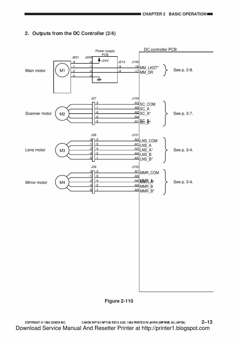
7/16/2019 Canon Np7161-Np7160 Copier Sm
http://slidepdf.com/reader/full/canon-np7161-np7160-copier-sm 51/345
COPYRIGHT © 1998 CANON INC. CANON NP7161/NP7160 REV.0 AUG. 1998 PRINTED IN JAPAN (IMPRIME AU JAPON) 2–13
CHAPTER 2 BASIC OPERATION
2. Outputs from the DC Controller (2/4)
Figure 2-110
DC controller PCB
+24V J106
-16
-17
J601
-4
-1
-2
-3
J212
-9
-8
J209
-4
-1
-2
-3
Main motor MM_DRMM_LKDT*
See p. 2-8.
See p. 3-7.
See p. 3-4.
See p. 3-4.
M1
Power supplyPCB
Scanner motor
-3
-5
-4
-2
-1
-3
-1
-2
-4
-5
J101
-A3
-A1
-A2
-A4
-A5
Lens motorLNS_ALNS_COM
LNS_A*LNS_BLNS_B*
J38
M3
-3
-1
-4
-2
-5
J104
-A3
-A5
-A2
-A4
-A1
SC_ASC_COM
SC_A*
SC_BSC_B*
J37
M2
-3
-5
-4
-2
-1
-3
-1
-2
-4
-5
J103
-A7
-A5
-A6
-A8
-A9
Mirror motor MMR_A
MMR_COM
MMR_A*MMR_BMMR_B*
J39
M4
Download Service Manual And Resetter Printer at http://printer1.blogspot.com
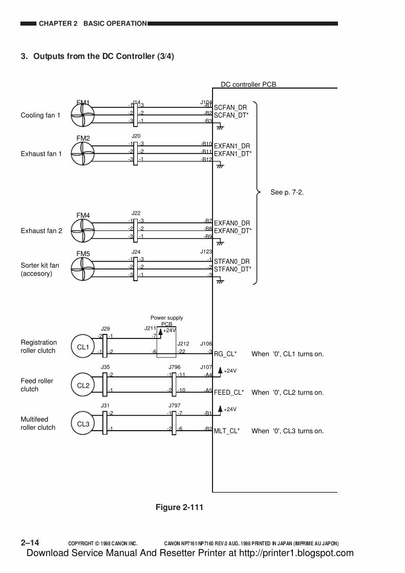
7/16/2019 Canon Np7161-Np7160 Copier Sm
http://slidepdf.com/reader/full/canon-np7161-np7160-copier-sm 52/345
2–14 COPYRIGHT © 1998 CANON INC. CANON NP7161/NP7160 REV.0 AUG. 1998 PRINTED IN JAPAN (IMPRIME AU JAPON)
CHAPTER 2 BASIC OPERATION
3. Outputs from the DC Controller (3/4)
Figure 2-111
DC controller PCB
J104-B1
-B2
-B3Cooling fan 1 SCFAN_DT*
SCFAN_DRFM1 -3
-2
-1
-1
-2
-3
J14
-B10
-B11
-B12Exhaust fan 1 EXFAN1_DT*
EXFAN1_DRFM2
-3
-2
-1
J20
-B7
-B8
-B9Exhaust fan 2 EXFAN0_DT*
EXFAN0_DRFM4
FM5
-3
-2
-1
-1
-2
-3
-1
-2
-3
J22
J24 J123
-1
-2
-3
Sorter kit fan(accesory)
STFAN0_DT*STFAN0_DR-3
-2
-1
-1
-2
-3
See p. 7-2.
+24V
J212
-22
J106
-3
Registrationroller clutch
RG_CL* When '0', CL1 turns on.CL1
J211
-7
-6
+24V-11
-10
J107
-A4
-A5
Feed rollerclutch
FEED_CL* When '0', CL2 turns on.
J796
CL2
-1
-2
-2
-1
J35
J29
-1
-2
-2
-1
+24V-7
-6
-B1
-B2 MLT_CL* When '0', CL3 turns on.
J797
CL3
-1
-2
-2
-1
J31
Multifeedroller clutch
Power supplyPCB
Download Service Manual And Resetter Printer at http://printer1.blogspot.com
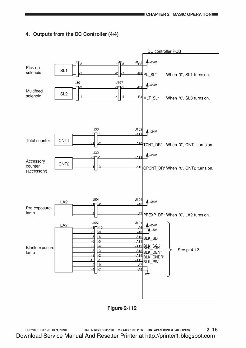
7/16/2019 Canon Np7161-Np7160 Copier Sm
http://slidepdf.com/reader/full/canon-np7161-np7160-copier-sm 53/345
COPYRIGHT © 1998 CANON INC. CANON NP7161/NP7160 REV.0 AUG. 1998 PRINTED IN JAPAN (IMPRIME AU JAPON) 2–15
CHAPTER 2 BASIC OPERATION
4. Outputs from the DC Controller (4/4)
Figure 2-112
DC controller PCB
+24VJ102
-A11
-A10Total counter
TCNT_DR* When '0', CNT1 turns on.CNT1
-1
-2
J33
+24V-A13
-A12
Accessorycounter(accessory)
OPCNT_DR* When '0', CNT2 turns on.CNT2
-1
-3
-2
-1
-3
-1
J32
+24VJ104
-A6
-A7
Pre-exposurelamp
PREXP_DR* When '0', LA2 turns on.
LA2-2
-1
-1
-2
J501
+24V
+5V
J101
-A6
-A8
-A10
-A11
-A12
-A13
-A14
-A15
-A7
-A9
Blank exposurelamp
BLK_SD
BLK_SCKBLK_LCKBLK_DEN*BLK_CNDR*BLK_PW
LA3-10
-8
-6
-5
-4
-3
-2
-1
-9
-7
-1
-3
-5
-6
-7
-8
-9
-10
-2
-4
J551
+24VJ107-B8
-B9
Pick-upsolenoid
PU_SL* When '0', SL1 turns on.SL1
-8
-7
J40-1
-2
-2
-1
J36
+24V-B3
-B4
Multifeedsolenoid
MLT_SL* When '0', SL3 turns on.SL2
-5
-4
J797
-3
-4
-2
-1
J30
See p. 4-12.
Download Service Manual And Resetter Printer at http://printer1.blogspot.com
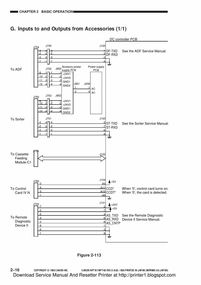
7/16/2019 Canon Np7161-Np7160 Copier Sm
http://slidepdf.com/reader/full/canon-np7161-np7160-copier-sm 54/345
2–16 COPYRIGHT © 1998 CANON INC. CANON NP7161/NP7160 REV.0 AUG. 1998 PRINTED IN JAPAN (IMPRIME AU JAPON)
CHAPTER 2 BASIC OPERATION
G. Inputs to and Outputs from Accessories (1/1)
Figure 2-113
DC controller PCB
+5VJ104
-A9
-A11
-A10
-A8
To ControlCard IV N
To ADF
CCD*CCDT*
-4-2
-3
-1
-4-2
-3
-1
J120
-1-3
-2
-4
J955
-1
-2
-3
-4
See the ADF Service Manual.
See the Sorter Service Manual.
See the Remote DiagnosticDevice II Service Manual.
When '0', control card turns on.When '0', the card is detected.
DF-RXDDF-TXD
J750J754
-1
-2
-3
-4
-9
-10
-11
-12
-4-2
-3
-1
-1
-2
-3
-4
J752Accesory power
supply PCB
Power supply
PCB
J952
-1-2
-3
-4
J206
-1
-4
J951
-1
-3
-1-2
-3
-4
J753
To Sorter
To CassetteFeedingModule-C1
-4
-2
-3
-1
-4
-2
-3
-1
-1-2
-3
-4
-9-10
-11
-12
-4
-2
-3
-1
J120
-5
-7
-6
-8
ST-RXDST-TXD
J751
J755
-2
-4
-3
-1
J790
+24V
+5V
J121
-2
-7
-4
-5
-6
-1
-3
-8
To RemoteDiagnosticDevice II
AS_RXDAS_CNTP
AS_TXD
-7
-2
-5
-4
-3
-8
-6
-1
J722
+24V1
+24V2
GND1
GND2AC
AC
+24V1
+24V2
GND1
GND2
J122J701
Download Service Manual And Resetter Printer at http://printer1.blogspot.com
7/16/2019 Canon Np7161-Np7160 Copier Sm
http://slidepdf.com/reader/full/canon-np7161-np7160-copier-sm 55/345
COPYRIGHT © 1998 CANON INC. CANON NP7161/NP7160 REV.0 AUG. 1998 PRINTED IN JAPAN (IMPRIME AU JAPON)
CHAPTER 3
EXPOSURE SYSTEM
I. OUTLINE OF OPERATION ..................... 3-1
A. Changing the Reproduction Ratio ...... 3-1II. LENS DRIVE SYSTEM ............................ 3-3
A. Driving the Lens ................................. 3-3
III. SCANNER DRIVE SYSTEM.................... 3-6A. Outline ................................................ 3-6
B. Scanner Motor Control Circuit ........... 3-7C. Relationship between Scanner Sensorand Signals ......................................... 3-7
D. Basic Sequence of Operations
(scanner) ........................................... 3-8
E. Scanner Movement inPage Separation Mode ...................... 3-9
IV. OTHERS................................................. 3-10
A. Detecting the Original Size .............. 3-10
V. DISASSEMBLY/ASSEMBLY ................. 3-11A. Scanner Drive Assembly .................. 3-12
B. Lens Drive Assembly ....................... 3-18
This chapter discusses the principles of operation used for the copier's lens drive unit and scanner drive
unit. It also explains the timing at which these drive units are operated, and shows how they may be
disassembled/assembled and adjusted.
Download Service Manual And Resetter Printer at http://printer1.blogspot.com

7/16/2019 Canon Np7161-Np7160 Copier Sm
http://slidepdf.com/reader/full/canon-np7161-np7160-copier-sm 56/345
Download Service Manual And Resetter Printer at http://printer1.blogspot.com

7/16/2019 Canon Np7161-Np7160 Copier Sm
http://slidepdf.com/reader/full/canon-np7161-np7160-copier-sm 57/345
COPYRIGHT © 1998 CANON INC. CANON NP7161/NP7160 REV.0 AUG. 1998 PRINTED IN JAPAN (IMPRIME AU JAPON) 3–1
CHAPTER 3 EXPOSURE SYSTEM
I. OUTLINE OF OPERATION
A. Changing the Reproduction Ratio
The reproduction ratio in the axial direction of the photosensitive drum is varied by the lensdrive system and the mirror drive system, and that in the peripheral direction of the
photosensitive drum is changed by the scanner drive system.
The lens drive system uses a lens array and, as shown in Figure 3-101, the lens position and
the optical length are varied to change the reproduction ratio in the axial direction of the
photosensitive drum.
The optical length is varied, as shown in Figure 3-102, by changing the location of the No. 4/
No. 5 mirror unit.
The scanner drive system moves the No. 1 mirror relatively faster (in Reduce) or slower (in
Enlarge) than the photosensitive drum (peripheral speed) to change the reproduction ratio in theperipheral direction of the photosensitive drum.
Note:
1. In Direct, the speed of the No. 1 mirror is made identical to the peripheral speed of the
photosensitive drum.
2. In both Reduce and Enlarge, the optical length is longer than in Direct.
Direct
Reduce
Enlarge
Optical length
F
F
F
F'
F'
F'
L3
Optical length L2
Optical lengthL1
Figure 3-101
Download Service Manual And Resetter Printer at http://printer1.blogspot.com
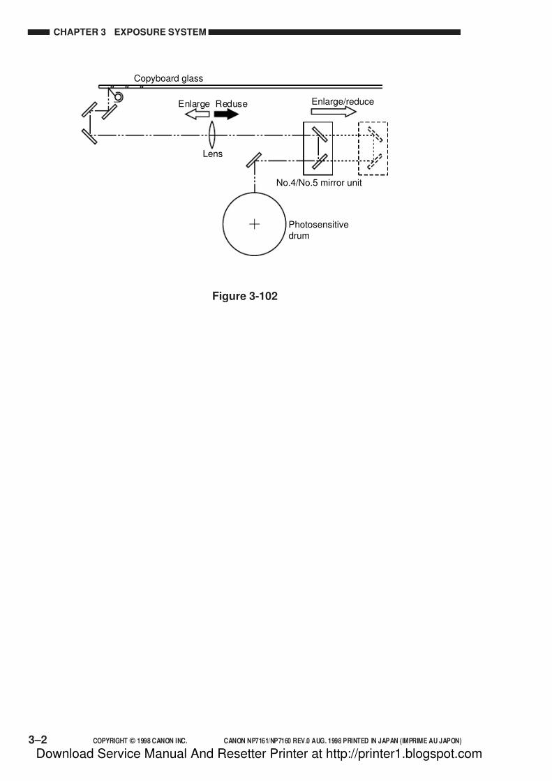
7/16/2019 Canon Np7161-Np7160 Copier Sm
http://slidepdf.com/reader/full/canon-np7161-np7160-copier-sm 58/345
3–2 COPYRIGHT © 1998 CANON INC. CANON NP7161/NP7160 REV.0 AUG. 1998 PRINTED IN JAPAN (IMPRIME AU JAPON)
CHAPTER 3 EXPOSURE SYSTEM
Figure 3-102
Copyboard glass
Lens
No.4/No.5 mirror unit
Photosensitivedrum
Enlarge Reduse Enlarge/reduce
Download Service Manual And Resetter Printer at http://printer1.blogspot.com

7/16/2019 Canon Np7161-Np7160 Copier Sm
http://slidepdf.com/reader/full/canon-np7161-np7160-copier-sm 59/345
COPYRIGHT © 1998 CANON INC. CANON NP7161/NP7160 REV.0 AUG. 1998 PRINTED IN JAPAN (IMPRIME AU JAPON) 3–3
CHAPTER 3 EXPOSURE SYSTEM
II. LENS DRIVE SYSTEM
A. Driving the Lens
1. OutlineThe lens is driven by the lens motor (M3) and the mirror motor (M4).
As shown in Figure 3-201, when the lens motor rotates in normal direction, the lens moves in
the direction of Enlarge by the drive coming through gears and drive belt.
At this time, the No. 4/No. 5 mirror unit moves by the drive coming from the mirror motor in
the direction of Enlarge/Reduce according to how much the lens moves (reproduction ratio),
thereby varying the optical length.
Figure 3-201
DCcontrollerPCB
Lens home positionsensor (PS2)
Mirror home positionsensor (PS3)
Mirror motor (M4)
Enlarge/Reduce
Mirror motor drive command
Mirror home positiondetection signal (MRRHP)
Direct
Enlarge
CW
CCW
Lens home position detection signal (LNSHP)
Reduce
Lensmotor (M3)Lens
motordrive command
Download Service Manual And Resetter Printer at http://printer1.blogspot.com
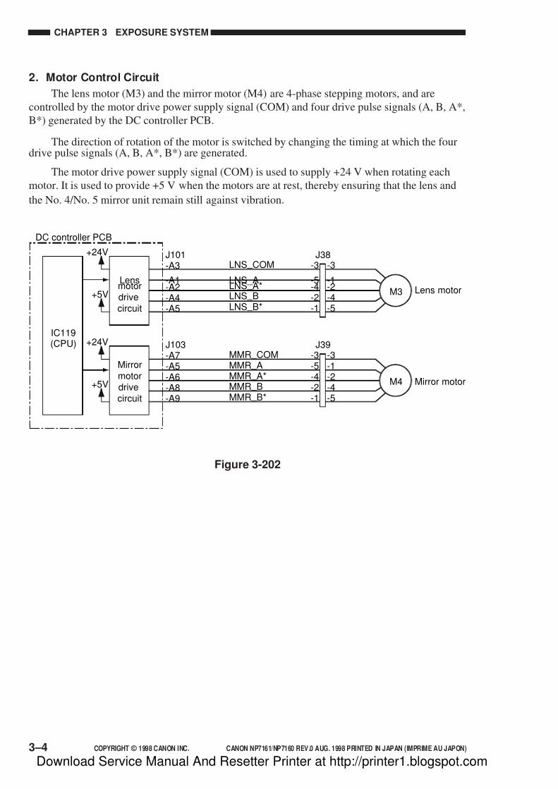
7/16/2019 Canon Np7161-Np7160 Copier Sm
http://slidepdf.com/reader/full/canon-np7161-np7160-copier-sm 60/345
3–4 COPYRIGHT © 1998 CANON INC. CANON NP7161/NP7160 REV.0 AUG. 1998 PRINTED IN JAPAN (IMPRIME AU JAPON)
CHAPTER 3 EXPOSURE SYSTEM
2. Motor Control Circuit
The lens motor (M3) and the mirror motor (M4) are 4-phase stepping motors, and are
controlled by the motor drive power supply signal (COM) and four drive pulse signals (A, B, A*,
B*) generated by the DC controller PCB.
The direction of rotation of the motor is switched by changing the timing at which the fourdrive pulse signals (A, B, A*, B*) are generated.
The motor drive power supply signal (COM) is used to supply +24 V when rotating each
motor. It is used to provide +5 V when the motors are at rest, thereby ensuring that the lens and
the No. 4/No. 5 mirror unit remain still against vibration.
-3
-5-4-2-1
-3
-1-2-4-5
J101-A3
-A1-A2-A4-A5
Lens motorLNS _ A
LNS _ COM
LNS _ A*LNS _ BLNS _ B*
J38
M3
-3-5-4-2-1
-3-1-2-4-5
J103-A7-A5-A6-A8-A9
Mirror motor
MMR _ AMMR _ COM
MMR _ A*MMR _ BMMR _ B*
J39
M4
Lensmotordrivecircuit
DC controller PCB
+5V
+24V
Mirrormotordrivecircuit
IC119(CPU)
+5V
+24V
Figure 3-202
Download Service Manual And Resetter Printer at http://printer1.blogspot.com

7/16/2019 Canon Np7161-Np7160 Copier Sm
http://slidepdf.com/reader/full/canon-np7161-np7160-copier-sm 61/345
COPYRIGHT © 1998 CANON INC. CANON NP7161/NP7160 REV.0 AUG. 1998 PRINTED IN JAPAN (IMPRIME AU JAPON) 3–5
CHAPTER 3 EXPOSURE SYSTEM
3. Moving the Lens
The lens and the No. 4/ No. 5 mirror unit are moved with reference to the points at which
the lens home position sensor (PS2) and the mirror home position sensor (PS3) turn on.
The number of pulses (indicating the positions of the lens and the No. 4/ No. 5 mirror)
applied to each motor is stored in memory by the microprocessor on the DC controller PCB.When the lens and the No. 4/ No. 5 mirror unit need to be moved, the appropriate number of
pulses that suits the selected reproduction ratio is generated.
When the lens and the No. 4/ No. 5 mirror unit need to be moved in the direction of
reduction (e.g., from Direct to Reduce), each motor is rotated in reverse first to move the lens
and the No. 4/ No. 5 mirror unit past the position found for the selected reproduction ratio.
Thereafter, the motors are rotated in normal direction so as to move the lens and the No. 4/ No. 5
mirror unit to their appropriate positions. Ending the motor rotation when they are rotating in
normal direction ensures accurate positioning of the lens and the No. 4/ No. 5 mirror unit.
Figure 3-203
The copier enables adjustment of the lens or the No. 4/No. 5 mirror unit home position in
service mode.
Power switchON
Reducekey ON
Start keyON
Lens motor (M3)
Scanner motor (M2)
WMUP WMUPR INTRSTBY
* * * *
Sequence
Mirror motor (M4)
Scanner home positionsensor (PS1)
Lens home positionsensor (PS2)
Mirror home positionsensor (PS3)
Enlargekey ON
: Motor CW/sensor ON : Motor CCW
*Length varies depending on the selected reproduction ratio.
Download Service Manual And Resetter Printer at http://printer1.blogspot.com

7/16/2019 Canon Np7161-Np7160 Copier Sm
http://slidepdf.com/reader/full/canon-np7161-np7160-copier-sm 62/345
3–6 COPYRIGHT © 1998 CANON INC. CANON NP7161/NP7160 REV.0 AUG. 1998 PRINTED IN JAPAN (IMPRIME AU JAPON)
CHAPTER 3 EXPOSURE SYSTEM
III. SCANNER DRIVE SYSTEM
A. Outline
The scanner is driven by the scanner motor (M2)As shown in Figure 3-301, when the scanner motor rotates in reverse direction, the scanner
moves forward by the drive coming through the gears, drive belt, and cable. The scanner motor is
rotated in the opposite direction to move the scanner in reverse.
The speed of rotation of the scanner motor when the scanner is moved forward is varied
according to the selected reproduction ratio. The speed when the scanner is moved in reverse,
however, is the same regardless of the selected reproduction ratio—it is about 2.5 times the speed
used in Direct when the scanner is moved forward.
The distance over which the scanner is moved varies according to the length of copy paper
and the selected reproduction ratio.
Figure 3-301
FowardScanner homeposition sensor(PS1) S
c a n n e r h o m e p o s i t i o n d
e t e c t i o n s i g n a l
( S C H P )
Scannermotor (M2)
S c a n n e r m o t o r
d r i v e c o m m a n d
CCW
CW
Reverse
DC controller PCB
Download Service Manual And Resetter Printer at http://printer1.blogspot.com
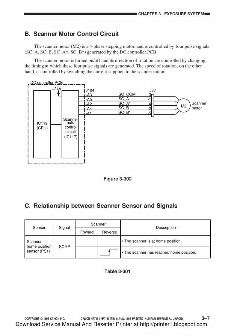
7/16/2019 Canon Np7161-Np7160 Copier Sm
http://slidepdf.com/reader/full/canon-np7161-np7160-copier-sm 63/345
COPYRIGHT © 1998 CANON INC. CANON NP7161/NP7160 REV.0 AUG. 1998 PRINTED IN JAPAN (IMPRIME AU JAPON) 3–7
CHAPTER 3 EXPOSURE SYSTEM
B. Scanner Motor Control Circuit
The scanner motor (M2) is a 4-phase stepping motor, and is controlled by four pulse signals
(SC_A, SC_B, SC_A*, SC_B*) generated by the DC controller PCB.
The scanner motor is turned on/off and its direction of rotation are controlled by changing
the timing at which these four pulse signals are generated. The speed of rotation, on the other
hand, is controlled by switching the current supplied to the scanner motor.
Figure 3-302
C. Relationship between Scanner Sensor and Signals
Table 3-301
Scannerhome positionsensor (PS1)
• The scanner is at home position.
• The scanner has reached home position.
Sensor SignalScanner
Foward Reverse
SCHP
Description
-3-1-4-2-5
J104-A3-A5-A2-A4-A1
Scannermotor
SC_ASC_COM
SC_A*SC_BSC_B*
J37
M2
Scannermotorcontrolcircuit
DC controller PCB
+24V
(IC117)
IC119(CPU)
Download Service Manual And Resetter Printer at http://printer1.blogspot.com
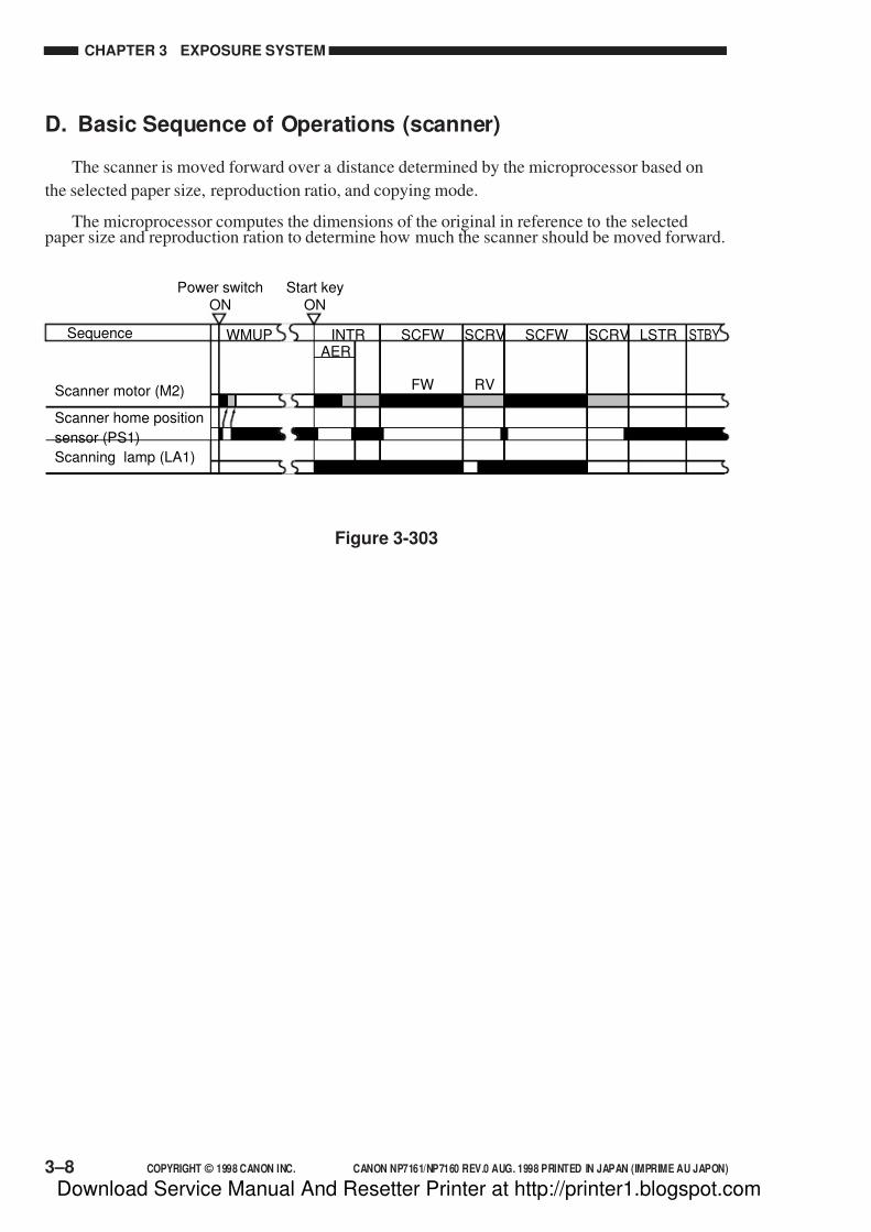
7/16/2019 Canon Np7161-Np7160 Copier Sm
http://slidepdf.com/reader/full/canon-np7161-np7160-copier-sm 64/345
3–8 COPYRIGHT © 1998 CANON INC. CANON NP7161/NP7160 REV.0 AUG. 1998 PRINTED IN JAPAN (IMPRIME AU JAPON)
CHAPTER 3 EXPOSURE SYSTEM
D. Basic Sequence of Operations (scanner)
The scanner is moved forward over a distance determined by the microprocessor based on
the selected paper size, reproduction ratio, and copying mode.
The microprocessor computes the dimensions of the original in reference to the selectedpaper size and reproduction ration to determine how much the scanner should be moved forward.
Figure 3-303
Start keyON
Power switchON
WMUP
FW RV
STBYLSTRSCRVSCFWSCRVSCFWINTRAER
Sequence
Scanner motor (M2)
Scanner home position
sensor (PS1)
Scanning lamp (LA1)
Download Service Manual And Resetter Printer at http://printer1.blogspot.com

7/16/2019 Canon Np7161-Np7160 Copier Sm
http://slidepdf.com/reader/full/canon-np7161-np7160-copier-sm 65/345
COPYRIGHT © 1998 CANON INC. CANON NP7161/NP7160 REV.0 AUG. 1998 PRINTED IN JAPAN (IMPRIME AU JAPON) 3–9
CHAPTER 3 EXPOSURE SYSTEM
E. Scanner Movement in Page Separation Mode
Figure 3-304
I, II, and III shown in Figure 3-304 are controlled by the microprocessor on the DC controller
PCB with reference to the wait position of the scanner.
The length from wait position to the leading edge is 18 mm. The microprocessor determines
how much the scanner should be moved (including the distance to the leading edge) according to
the selected reproduction ratio and the original size or cassette size.
I, II : The distance over which the scanner is moved forward for the 1st page is determined
according to the selected reproduction ratio and the original size or cassette size.
III : The distance over which the scanner is moved forward is determined as follows: the
microprocessor divides the detected original size by 2, and assumes the result of thedivision to be the middle of the original (assuming the middle to be the leading edge
of the 2nd page).
If original size detection is not performed, the microprocessor uses the cassette size when
determining the distance over which the scanner should be moved.
Reference:
The copier does not require paper size registration for the multifeeder. For this reason, it
cancels Page Separate mode if the Start key is pressed after selecting the multifeeder.
Start keyON
Leading edge of
1st page (original)Leading edge of
1st page (original)Leading edge of
2nd page (original)
FW RV
LSTRSCRV2SCFW2SCRV2SCFW1INTRAER
Sequence
Scanner motor (M2)
Scanner home positionsensor (PS1)
Scanning lamp (LA1)
18mm
I
18mm
II III
Download Service Manual And Resetter Printer at http://printer1.blogspot.com

7/16/2019 Canon Np7161-Np7160 Copier Sm
http://slidepdf.com/reader/full/canon-np7161-np7160-copier-sm 66/345
3–10 COPYRIGHT © 1998 CANON INC. CANON NP7161/NP7160 REV.0 AUG. 1998 PRINTED IN JAPAN (IMPRIME AU JAPON)
CHAPTER 3 EXPOSURE SYSTEM
IV. OTHERS
A. Detecting the Original Size
1. OutlineThe NP7161 is equipped with auto paper selection and auto reproduction selection
functions, and these functions require identification of the size of originals.
To enable identification, the copier uses the following:
• original size detection by the ADF (NP7161)
2. Detection of the Original Size by the ADF
The size of originals is detected when originals are fed by the ADF. (For details, see the
ADF Service Manual.)
Download Service Manual And Resetter Printer at http://printer1.blogspot.com

7/16/2019 Canon Np7161-Np7160 Copier Sm
http://slidepdf.com/reader/full/canon-np7161-np7160-copier-sm 67/345
COPYRIGHT © 1998 CANON INC. CANON NP7161/NP7160 REV.0 AUG. 1998 PRINTED IN JAPAN (IMPRIME AU JAPON) 3–11
CHAPTER 3 EXPOSURE SYSTEM
V. DISASSEMBLY/ASSEMBLY
The copier may be disassembled and assembled as shown here. Pay attention to the copier's
mechanical characteristics along with the steps for disassembly/assembly.
Important:
1. Turn off the power and disconnect the power plug to ensure safety whenever disassembling/
assembling the copier.
2. Unless otherwise noted, assemble the parts by reversing the steps used to disassemble them.
3. Identify the screws by type (length, diameter) to avoid use in the wrong location.
4. Use a washer where needed. The mounting screws used for the grounding wire and varistor
come with a washer to ensure electric continuity. Do not forget to use these washers.
5. As a rule, do not operate the copier with any of its parts removed.
Download Service Manual And Resetter Printer at http://printer1.blogspot.com

7/16/2019 Canon Np7161-Np7160 Copier Sm
http://slidepdf.com/reader/full/canon-np7161-np7160-copier-sm 68/345
3–12 COPYRIGHT © 1998 CANON INC. CANON NP7161/NP7160 REV.0 AUG. 1998 PRINTED IN JAPAN (IMPRIME AU JAPON)
CHAPTER 3 EXPOSURE SYSTEM
A. Scanner Drive Assembly
1. Removing the Scanner Motor
1) Remove the rear upper cover.
2) Disconnect the connector [1] and the twomounting screws [2].
3) Slide the scanner motor [3] to the right to
detach from the motor mount; then, move
it to the cut-off [A] to remove.
[1][2]
[A]
[3]
Figure 3-502
Figure 3-501
Download Service Manual And Resetter Printer at http://printer1.blogspot.com

7/16/2019 Canon Np7161-Np7160 Copier Sm
http://slidepdf.com/reader/full/canon-np7161-np7160-copier-sm 69/345
COPYRIGHT © 1998 CANON INC. CANON NP7161/NP7160 REV.0 AUG. 1998 PRINTED IN JAPAN (IMPRIME AU JAPON) 3–13
CHAPTER 3 EXPOSURE SYSTEM
Figure 3-503
[3]
[1] [2]
2. Removing the Scanner Drive Cable
1) In standby state, press the Reduce key so
that the lens and the No.4 /No.5 mirror
unit move to 70% reproduction position.
2) Turn off the power switch, and disconnectthe power plug.
Caution:
Whenever you need to perform
disassembly/assembly work, be sure to
turn it off and disconnect its power
plug.
3) Remove the lens hood.(See p. 3-20.)
4) Remove the scanner motor.
(See p. 3-12.)
5) Remove the control panel
(See p. 7-13.)
6) Remove the upper left cover.
(See p.7-11.)
7) Remove the upper right cover.
(See p.7-10.)
8) Detach the lock support [1] from the
connector base [2].
9) Remove the two mounting screws [3], and
pull out the connector base [2].
Download Service Manual And Resetter Printer at http://printer1.blogspot.com
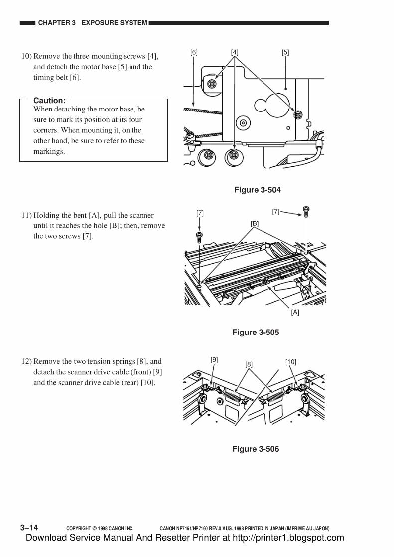
7/16/2019 Canon Np7161-Np7160 Copier Sm
http://slidepdf.com/reader/full/canon-np7161-np7160-copier-sm 70/345
3–14 COPYRIGHT © 1998 CANON INC. CANON NP7161/NP7160 REV.0 AUG. 1998 PRINTED IN JAPAN (IMPRIME AU JAPON)
CHAPTER 3 EXPOSURE SYSTEM
[4] [5][6]
[B]
[7]
[A]
[7]
Figure 3-504
Figure 3-506
Figure 3-505
[8][9] [10]
10) Remove the three mounting screws [4],
and detach the motor base [5] and the
timing belt [6].
Caution:When detaching the motor base, be
sure to mark its position at its four
corners. When mounting it, on the
other hand, be sure to refer to these
markings.
11) Holding the bent [A], pull the scanner
until it reaches the hole [B]; then, remove
the two screws [7].
12) Remove the two tension springs [8], and
detach the scanner drive cable (front) [9]
and the scanner drive cable (rear) [10].
Download Service Manual And Resetter Printer at http://printer1.blogspot.com

7/16/2019 Canon Np7161-Np7160 Copier Sm
http://slidepdf.com/reader/full/canon-np7161-np7160-copier-sm 71/345
COPYRIGHT © 1998 CANON INC. CANON NP7161/NP7160 REV.0 AUG. 1998 PRINTED IN JAPAN (IMPRIME AU JAPON) 3–15
CHAPTER 3 EXPOSURE SYSTEM
3. Routing the Scanner Drive Cable
Route the scanner drive cable following the sequence indicated in Figure 3-507, i.e., [1]
through [7].
Be sure to adjust the mirror position and the tension as indicated later after routing the
scanner drive cable.
[4][3]
[2]
[6]
[2]
[6]
[1]
Secure temporarily.
Steelball
Wind 11 times.
[5]
[7]
Figure 3-507
Download Service Manual And Resetter Printer at http://printer1.blogspot.com

7/16/2019 Canon Np7161-Np7160 Copier Sm
http://slidepdf.com/reader/full/canon-np7161-np7160-copier-sm 72/345
3–16 COPYRIGHT © 1998 CANON INC. CANON NP7161/NP7160 REV.0 AUG. 1998 PRINTED IN JAPAN (IMPRIME AU JAPON)
CHAPTER 3 EXPOSURE SYSTEM
Figure 3-508a (Rear) Figure 3-508b (Front)
[1][2]
[1][2]
Figure 3-509a (Rear) Figure 3-509b (Front)
4. Adjusting the Position of the Mirror
Be sure to adjust the position of the mirror
as follows after you have mounted the
scanner drive cable.
1) Keep the mirror positioning tool nearby.Arrange the mirror positioning tool (FY9-
3009-050) as shown to adapt it to the
copier.
2) Fit the mirror positioning tool [1] to the
No. 1 mirror base and the No. 2 mirror
base (both front and rear).
3) Tighten the mounting screw [2] on the
cable metal fixing of the No. 1 mirror
base (both front and rear).
4) Detach the mirror positioning tool.
Download Service Manual And Resetter Printer at http://printer1.blogspot.com

7/16/2019 Canon Np7161-Np7160 Copier Sm
http://slidepdf.com/reader/full/canon-np7161-np7160-copier-sm 73/345
COPYRIGHT © 1998 CANON INC. CANON NP7161/NP7160 REV.0 AUG. 1998 PRINTED IN JAPAN (IMPRIME AU JAPON) 3–17
CHAPTER 3 EXPOSURE SYSTEM
10mm
10mm
S c a n n e r
[1][1][A]
Figure 3-510 Figure 3-511
5. Adjusting the Tension of theScanner Drive Cable
Be sure to adjust the tension as follows
after routing the scanner drive cable.
1) Move the scanner to home position.2) Pull the center of the scanner drive cable
with a spring gauge about 10 mm. At this
time, adjust the position [A] of the tension
spring [1] so that the reading of the spring
gauge is 95 ±15 g.
Download Service Manual And Resetter Printer at http://printer1.blogspot.com

7/16/2019 Canon Np7161-Np7160 Copier Sm
http://slidepdf.com/reader/full/canon-np7161-np7160-copier-sm 74/345
3–18 COPYRIGHT © 1998 CANON INC. CANON NP7161/NP7160 REV.0 AUG. 1998 PRINTED IN JAPAN (IMPRIME AU JAPON)
CHAPTER 3 EXPOSURE SYSTEM
B. Lens Drive Assembly
1. Removing the Lens Drive Motor
1) Remove the copyboard glass. (See p.7-14)
2) Holding the bend [A], slide out thescanner as far as the cut-off [B].
3) Remove the inside cover and the delivery
upper cover. (See p.7-11)
4) Disconnect the connector [1].
5) Remove the two screws [2], and remove
the lens motor [3].
[A]
[B]
[B]
Figure 3-512
[1]
Figure 3-514
Figure 3-513
[2]
[3]
[2]
Download Service Manual And Resetter Printer at http://printer1.blogspot.com
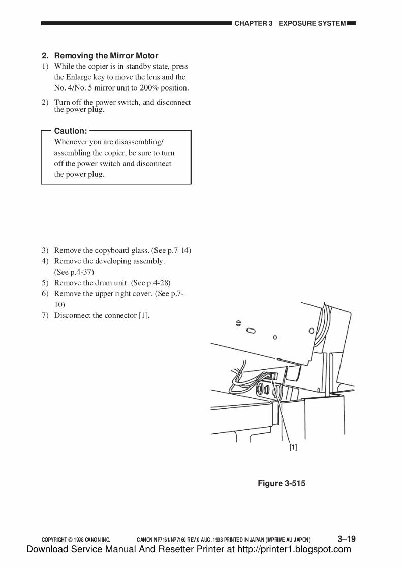
7/16/2019 Canon Np7161-Np7160 Copier Sm
http://slidepdf.com/reader/full/canon-np7161-np7160-copier-sm 75/345
COPYRIGHT © 1998 CANON INC. CANON NP7161/NP7160 REV.0 AUG. 1998 PRINTED IN JAPAN (IMPRIME AU JAPON) 3–19
CHAPTER 3 EXPOSURE SYSTEM
2. Removing the Mirror Motor
1) While the copier is in standby state, press
the Enlarge key to move the lens and the
No. 4/No. 5 mirror unit to 200% position.
2) Turn off the power switch, and disconnectthe power plug.
Caution:
Whenever you are disassembling/
assembling the copier, be sure to turn
off the power switch and disconnect
the power plug.
3) Remove the copyboard glass. (See p.7-14)
4) Remove the developing assembly.
(See p.4-37)
5) Remove the drum unit. (See p.4-28)
6) Remove the upper right cover. (See p.7-
10)
7) Disconnect the connector [1].
Figure 3-515
[1]
Download Service Manual And Resetter Printer at http://printer1.blogspot.com
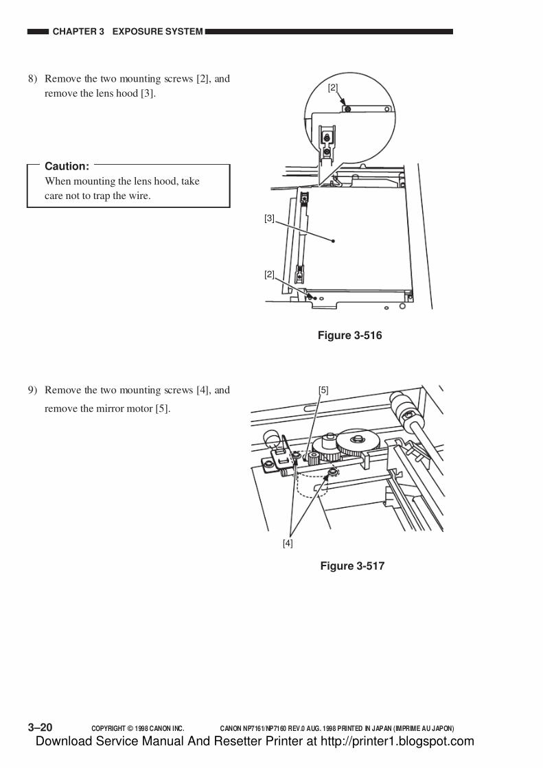
7/16/2019 Canon Np7161-Np7160 Copier Sm
http://slidepdf.com/reader/full/canon-np7161-np7160-copier-sm 76/345
3–20 COPYRIGHT © 1998 CANON INC. CANON NP7161/NP7160 REV.0 AUG. 1998 PRINTED IN JAPAN (IMPRIME AU JAPON)
CHAPTER 3 EXPOSURE SYSTEM
Figure 3-516
[3]
[2]
[2]
[5]
[4]
Figure 3-517
8) Remove the two mounting screws [2], and
remove the lens hood [3].
Caution:
When mounting the lens hood, take
care not to trap the wire.
9) Remove the two mounting screws [4], and
remove the mirror motor [5].
Download Service Manual And Resetter Printer at http://printer1.blogspot.com
7/16/2019 Canon Np7161-Np7160 Copier Sm
http://slidepdf.com/reader/full/canon-np7161-np7160-copier-sm 77/345
COPYRIGHT © 1998 CANON INC. CANON NP7161/NP7160 REV.0 AUG. 1998 PRINTED IN JAPAN (IMPRIME AU JAPON)
CHAPTER 4
IMAGE FORMATION SYSTEM
I. OUTLINE OF THE PROCESSES ............ 4-1A. Outline ................................................ 4-1B. Basic Sequence of Operations
(image formation system) .................. 4-2
C. Controlling the Intensity of theScanning Lamp .................................. 4-3
D. Controlling the Primary/Transfer Bias .. 4-6
E. Controlling the Developing/SeparationStatic Eliminator Bias ......................... 4-7
F. Controlling the Blank Exposure Lamp ... 4-12
II. DEVELOPING ASSEMBLY/DRUMCLEANER ASSEMBLY.......................... 4-14
A. Outline .............................................. 4-14B. Detecting and Controlling
the Level of Toner ............................ 4-16
C. Monitoring the Waste TonerFeeding Screw ................................. 4-17
D. Monitoring the Waste Toner Box ..... 4-18E. Control by the Cleaner Thermistor... 4-20
F. Auto Density Adjustment (AE) ......... 4-21
III. DISASSEMBLY/ASSEMBLY ................. 4-23A. Scanning Lamp Assembly ............... 4-24
B. Exposure Assembly ......................... 4-26
C. Drum Unit ......................................... 4-28D. Primary Charging Assembly ............ 4-30
E. Transfer Charging Assembly ........... 4-31
F. Charging Wire .................................. 4-32
G. Developing Assembly....................... 4-37
This chapter discusses the principles of how images are formed. It also explains the timing at which the
various units involved in image formation are operated, and shows how they may be disassembled/
assembled and adjusted.
Download Service Manual And Resetter Printer at http://printer1.blogspot.com

7/16/2019 Canon Np7161-Np7160 Copier Sm
http://slidepdf.com/reader/full/canon-np7161-np7160-copier-sm 78/345
Download Service Manual And Resetter Printer at http://printer1.blogspot.com

7/16/2019 Canon Np7161-Np7160 Copier Sm
http://slidepdf.com/reader/full/canon-np7161-np7160-copier-sm 79/345
COPYRIGHT © 1998 CANON INC. CANON NP7161/NP7160 REV.0 AUG. 1998 PRINTED IN JAPAN (IMPRIME AU JAPON) 4–1
CHAPTER 4 IMAGE FORMATION SYSTEM
I. OUTLINE OF THE PROCESSES
A. Outline
Figure 4-101 shows the copier's basic construction in reference to image formation. Imageformation consists of the following functions:
• Scanning lamp control
• Primary corona current control
• Transfer control current control
• Separation static eliminator bias control
• Developing bias control
• Blank exposure lamp control
Figure 4-101
AE sensor
DC controller PCB
Scanning lamp (LA1) Lens
Copy board glass
No.1mirror
No.2mirror
No.3mirror
No.4 mirror
No.5 mirror
Developingassembly
A
E
s e n s o r o u t p u t s i g n a l ( A E_
D A T A )
No.6mirrorBlank
exposurelamp (LA3)
Pre-exposurelamp (LA2)
Primarycoronaassembly
Transfercoronaassembly
Staticeliminator
HVT
Lamp regulatorPCB
Download Service Manual And Resetter Printer at http://printer1.blogspot.com

7/16/2019 Canon Np7161-Np7160 Copier Sm
http://slidepdf.com/reader/full/canon-np7161-np7160-copier-sm 80/345
CHAPTER 4 IMAGE FORMATION SYSTEM
4–2 COPYRIGHT © 1998 CANON INC. CANON NP7161/NP7160 REV.0 AUG. 1998 PRINTED IN JAPAN (IMPRIME AU JAPON)
B. Basic Sequence of Operations (image formation system)
Figure 4-102
Start keyON
STBY STBYLSTRSCRVSCFWSCRVSCFWINTRAER
Sequence
Main motor (M1)
Primary charging assembly
Developing DC bias
Developing AC bias
Transfer charging assembly
Static eliminator
Pre-exposure lamp (LA2)
Blank exposure lamp (LA3)
Scanning lamp (LA1)
Voltage control
Partial activation
Download Service Manual And Resetter Printer at http://printer1.blogspot.com

7/16/2019 Canon Np7161-Np7160 Copier Sm
http://slidepdf.com/reader/full/canon-np7161-np7160-copier-sm 81/345
COPYRIGHT © 1998 CANON INC. CANON NP7161/NP7160 REV.0 AUG. 1998 PRINTED IN JAPAN (IMPRIME AU JAPON) 4–3
CHAPTER 4 IMAGE FORMATION SYSTEM
C. Controlling the Intensity of the Scanning Lamp
1. Outline
Figure 4-103 shows the circuit used to control the intensity of the scanning lamp, and the
circuit has the following functions:1. Turning on/off the scanning lamp
2. Controlling the intensity of the scanning lamp
• controlling the light to a specific intensity against fluctuations in power supply voltage
Lamp regulatorPCB
Power supplyPCB
DC controllerPCB
+5V
LMPDR
Scanning lamp(LA1)
Thermal fuse(FU1)
J501-1
-3
J203-1
-3
J501-4
-6
J503-1-2-3
-4-5
J211-5-4-3
-2-1
J106-4-8
-6
AC_24V_ONJ106-24
J106-24
J212-21-17
-19
Control
circuit
Drivecircuit
LMP_PWM
LMPDT
Errordetection
circuit
LampON
detection
IC113
IC119
(CPU)RL
+24V
Figure 4-103
Download Service Manual And Resetter Printer at http://printer1.blogspot.com

7/16/2019 Canon Np7161-Np7160 Copier Sm
http://slidepdf.com/reader/full/canon-np7161-np7160-copier-sm 82/345
CHAPTER 4 IMAGE FORMATION SYSTEM
4–4 COPYRIGHT © 1998 CANON INC. CANON NP7161/NP7160 REV.0 AUG. 1998 PRINTED IN JAPAN (IMPRIME AU JAPON)
2. Operation
a. Turning On/Off the Scanning Lamp
When the scanning lamp drive signal (LMPDR) is ‘0’, the output of the control circuit goes
‘0’, keeping the drive circuit from turning on and therefore not supplying the scanning lamp
(LA1) with AC power.When LMPDR is ‘1’, the output of the control circuit will be ‘1’, turning on the drive circuit
and thereby supplying the scanning lamp (LA1) with AC power.
b. Controlling the Intensity of the Scanning Lamp
The intensity of the scanning lamp is increased/decreased by controlling the voltage of the
power supplied to the scanning lamp according to the level of the pulse width modulation signal
(LMP_PWM) from the DC controller PCB.
LMP_PWM varies the pulse duty between 10% and 90% to suit the selected reproduction
ratio so as to control the voltage of the power supplied to the scanning lamp as shown in Table 4-101 (actual value).
Figure 4-104
Table 4-101
T
t
Pulse duty (%) = t / T x 100
Power supply Pulse duty
10 to 90%
10 to 90%
DC output
45 to 80V
98 to 175V
120V
230V
c. Detecting the Activation of the Scanning Lamp
The control circuit on the lamp regulator PCB generates the drive detection signal(LMPDT) at all times while the scanning lamp remains on, and sends the signal to the lamp
activation detection IC (IC113) on the DC controller PCB.
If the scanning lamp remains on for 21 sec or more, the error detection circuit will cause the
AC_24V_ON signal to go ‘0’, thereby cutting the supply of AC power to the lamp regulator
PCB.
If an error is identified in the scanning lamp, the DC controller PCB will cut the AC power
to the lamp regulator and, at the same time, will indicate ‘E220’ on the control panel.
Download Service Manual And Resetter Printer at http://printer1.blogspot.com
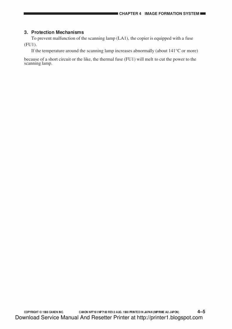
7/16/2019 Canon Np7161-Np7160 Copier Sm
http://slidepdf.com/reader/full/canon-np7161-np7160-copier-sm 83/345
COPYRIGHT © 1998 CANON INC. CANON NP7161/NP7160 REV.0 AUG. 1998 PRINTED IN JAPAN (IMPRIME AU JAPON) 4–5
CHAPTER 4 IMAGE FORMATION SYSTEM
3. Protection Mechanisms
To prevent malfunction of the scanning lamp (LA1), the copier is equipped with a fuse
(FU1).
If the temperature around the scanning lamp increases abnormally (about 141°C or more)
because of a short circuit or the like, the thermal fuse (FU1) will melt to cut the power to thescanning lamp.
Download Service Manual And Resetter Printer at http://printer1.blogspot.com

7/16/2019 Canon Np7161-Np7160 Copier Sm
http://slidepdf.com/reader/full/canon-np7161-np7160-copier-sm 84/345
CHAPTER 4 IMAGE FORMATION SYSTEM
4–6 COPYRIGHT © 1998 CANON INC. CANON NP7161/NP7160 REV.0 AUG. 1998 PRINTED IN JAPAN (IMPRIME AU JAPON)
Figure 4-108
2. Turning On/Off the Primary/Transfer Bias
a. When the primary/transfer bias is off,• When HVT_DR is 0,
Oscillation control circuit turns off
Primary/transfer high-voltage transformer turns off
b. When the primary/transfer bias is on,
• When HVT_DR is 1,
Oscillation control circuit turns on
Primary/transfer high-voltage transformer turns on
HVT
Tr
Pr
J301-8 Oscillation
control circuit
Transformer
Currentdetection circuit
Referencevoltage circuit
Short circuit/no loaddetection circuit
DC controllerPCB
Power supplyPCB
J212-10
J106-15
J210-3
HVT _ DR
D. Controlling the Primary/Transfer Bias
1. Outline
Figure 4-108 shows the circuit used to control the primary/transfer bias, and the circuit has
the following functions:1. Turning on/off the primary/transfer bias
2. Controlling the grid bias to a specific voltage
3. Controlling the primary shield current to a specific current
To eliminate the effects of changes in the environment to corona charging, the output to the
primary charging assembly is controlled by controlling the shield current to a specific current.
The primary/transfer bias is turned on/off using the following signal from the DC controller
PCB.
• HVT_DR (HVT drive command)
Download Service Manual And Resetter Printer at http://printer1.blogspot.com

7/16/2019 Canon Np7161-Np7160 Copier Sm
http://slidepdf.com/reader/full/canon-np7161-np7160-copier-sm 85/345
COPYRIGHT © 1998 CANON INC. CANON NP7161/NP7160 REV.0 AUG. 1998 PRINTED IN JAPAN (IMPRIME AU JAPON) 4–7
CHAPTER 4 IMAGE FORMATION SYSTEM
E. Controlling the Developing/Separation Static Eliminator Bias
1. Outline
Figure 4-109 shows the circuit used to control the developing/static eliminating bias, and the
circuit has the following functions:1. Turning on/off the developing DC bias
2. Turning on/off the developing AC bias/separation static eliminator bias
3. Controlling the developing DC bias to a specific voltage to suit copy density
The above control mechanisms are driven by the following signals:
• DV_AC_DR (developing AC bias drive signal)
• DV_AC_CNT (developing AC bias control signal)
• DV_DC_DR (developing DC bias drive signal)
• DV_DC_CNT (developing DC bias control signal)
Figure 4-109
Power supplyPCB HVT
SpDev
J301-6
J210-5
-7-4
-5-6
-4-7
Oscillationcontrol circuit
Short circuitdetection circuit
Voltagedetection circuit
Transformer
Oscillationcontrol circuit
Short circuit
detection circuit
Voltage
detection circuit
Transformer
Transformer
Frequencyswitching circuit
Oscillationcircuit
Amplifiercircuit
Controlcircuit
Referencevoltage circuit
Short circuitdetection circuit
Voltagedetection circuit
DC controllerPCB
J212-12
J106-13
DV _ AC _ CNT
-11-14DV _ AC _ DR
-13-12DV _ DC _ DR
-14-11DV _ DC _ CNT
Download Service Manual And Resetter Printer at http://printer1.blogspot.com

7/16/2019 Canon Np7161-Np7160 Copier Sm
http://slidepdf.com/reader/full/canon-np7161-np7160-copier-sm 86/345
CHAPTER 4 IMAGE FORMATION SYSTEM
4–8 COPYRIGHT © 1998 CANON INC. CANON NP7161/NP7160 REV.0 AUG. 1998 PRINTED IN JAPAN (IMPRIME AU JAPON)
Start keyON
STBY STBYLSTRSCRVSCFWSCRVSCFWINTRAER
Sequence
Developing DC bias
Developing AC bias
Voltagecontrol
Figure 4-110
2. Turning On/Off the Developing DC Bias
a. Turning On/Off the Developing DC Bias
• When DV_DC_DR is 0,
Oscillation control circuit turns off
DC high-voltage transformer turns off
The above condition deprives the developing cylinder of developing DC bias.
• When DV_DC_DR is 1,
Oscillation control circuit turns on
DC high-voltage transformer turns on
The above condition supplies the developing cylinder with developing DC bias.
b. Control Timing
As shown in Figure 4-110, a specific developing DC bias (-300 V) is applied to thedeveloping cylinder to prevent adhesion of excess toner to the photosensitive drum when copies
are not being made.
Download Service Manual And Resetter Printer at http://printer1.blogspot.com

7/16/2019 Canon Np7161-Np7160 Copier Sm
http://slidepdf.com/reader/full/canon-np7161-np7160-copier-sm 87/345
COPYRIGHT © 1998 CANON INC. CANON NP7161/NP7160 REV.0 AUG. 1998 PRINTED IN JAPAN (IMPRIME AU JAPON) 4–9
CHAPTER 4 IMAGE FORMATION SYSTEM
3. Turning On/Off the Developing AC Bias/Separation Eliminator Bias
a. Turning On/Off the Developing AC Bias
• When DV_AC_DR is 0,
control circuit turns off
oscillation circuit turns off amplification circuit turns off
AC high-voltage transformer turns off
The above condition deprives the developing cylinder of developing AC bias.
• When DV_AC_DR is 1,
control circuit turns on
oscillation circuit turns on
amplification circuit turns off
AC high-voltage transformer turns on
The above condition supplies the developing cylinder with AC bias.
b. Turning On/Off the Separation Static Eliminator
• When DV_AC_DR is 0,
oscillation control circuit turns off
high-voltage transformer turns off
The above condition deprives the static eliminator of separation static eliminator bias.
• When DV_AC_DR is 1,
oscillation control circuit turns on
high-voltage transformer turns on
The above condition supplies the static eliminator with separation static eliminator bias.
Download Service Manual And Resetter Printer at http://printer1.blogspot.com
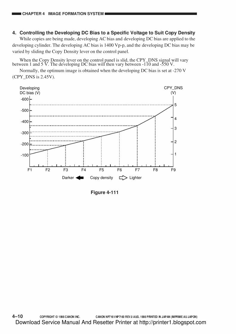
7/16/2019 Canon Np7161-Np7160 Copier Sm
http://slidepdf.com/reader/full/canon-np7161-np7160-copier-sm 88/345
CHAPTER 4 IMAGE FORMATION SYSTEM
4–10 COPYRIGHT © 1998 CANON INC. CANON NP7161/NP7160 REV.0 AUG. 1998 PRINTED IN JAPAN (IMPRIME AU JAPON)
Figure 4-111
F1 F2 F3 F4 F5 F6 F7 F8 F9
-600
DevelopingDC bias (V)
-500
-400
-300
-200
-100
Copy densityDarker Lighter
5
1
2
3
4
CPY _ DNS(V)
4. Controlling the Developing DC Bias to a Specific Voltage to Suit Copy Density
While copies are being made, developing AC bias and developing DC bias are applied to the
developing cylinder. The developing AC bias is 1400 Vp-p, and the developing DC bias may be
varied by sliding the Copy Density lever on the control panel.
When the Copy Density lever on the control panel is slid, the CPY_DNS signal will varybetween 1 and 5 V. The developing DC bias will then vary between -110 and -550 V.
Normally, the optimum image is obtained when the developing DC bias is set at -270 V
(CPY_DNS is 2.45V).
Download Service Manual And Resetter Printer at http://printer1.blogspot.com
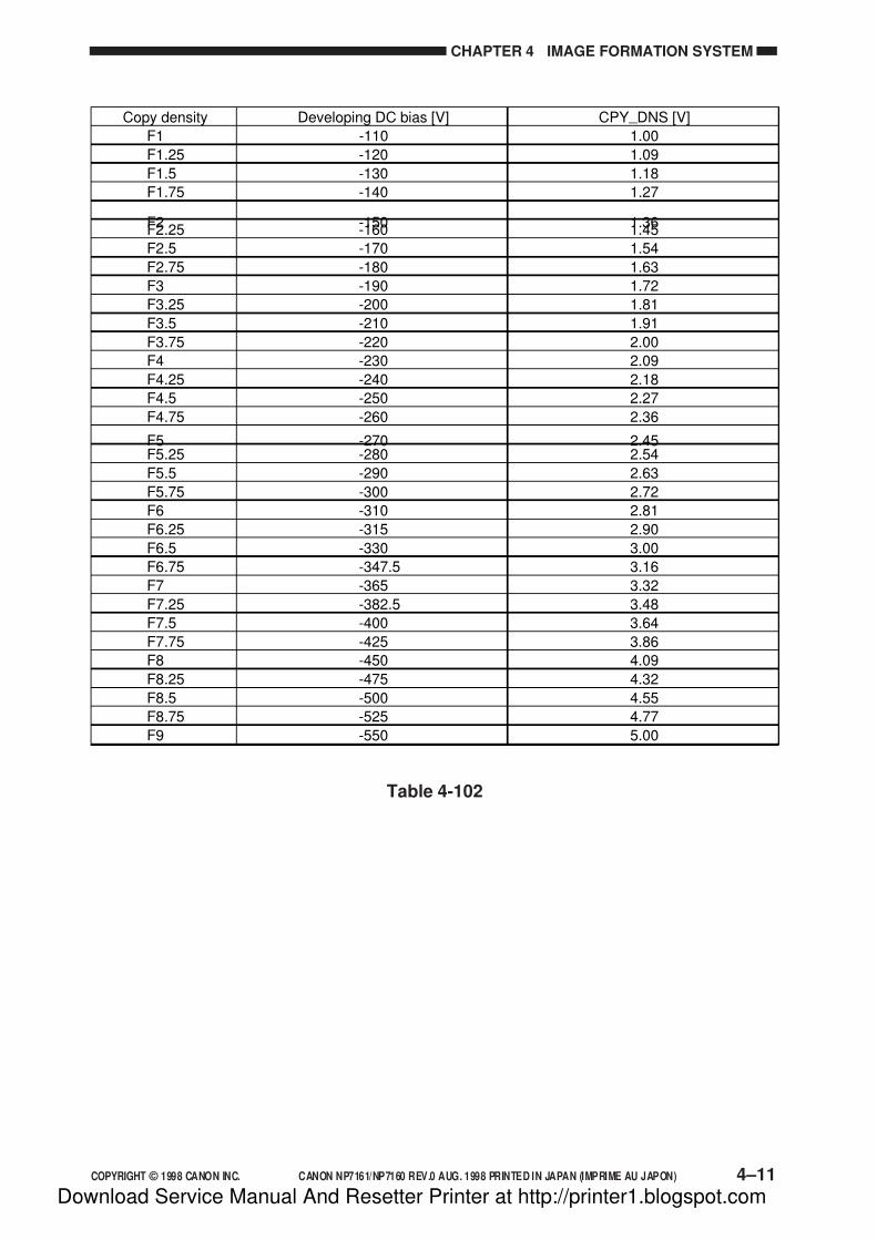
7/16/2019 Canon Np7161-Np7160 Copier Sm
http://slidepdf.com/reader/full/canon-np7161-np7160-copier-sm 89/345
COPYRIGHT © 1998 CANON INC. CANON NP7161/NP7160 REV.0 AUG. 1998 PRINTED IN JAPAN (IMPRIME AU JAPON) 4–11
CHAPTER 4 IMAGE FORMATION SYSTEM
Table 4-102
Developing DC bias [V]Copy density CPY _ DNS [V]
-110F1 1.00
-120F1.25 1.09
-130F1.5 1.18
-140F1.75 1.27
-150F2 1.36-160F2.25 1.45
-170F2.5 1.54
-180F2.75 1.63
-190F3 1.72
-200F3.25 1.81
-210F3.5 1.91
-220F3.75 2.00
-230F4 2.09
-240F4.25 2.18
-250F4.5 2.27
-260F4.75 2.36
-270F5 2.45-280F5.25 2.54
-290F5.5 2.63
-300F5.75 2.72
-310F6 2.81
-315F6.25 2.90
-330F6.5 3.00
-347.5F6.75 3.16
-365F7 3.32
-382.5F7.25 3.48
-400F7.5 3.64
-425F7.75 3.86
-450F8 4.09
-475F8.25 4.32
-500F8.5 4.55
-525F8.75 4.77
-550F9 5.00
Download Service Manual And Resetter Printer at http://printer1.blogspot.com

7/16/2019 Canon Np7161-Np7160 Copier Sm
http://slidepdf.com/reader/full/canon-np7161-np7160-copier-sm 90/345
CHAPTER 4 IMAGE FORMATION SYSTEM
4–12 COPYRIGHT © 1998 CANON INC. CANON NP7161/NP7160 REV.0 AUG. 1998 PRINTED IN JAPAN (IMPRIME AU JAPON)
Blank exposure lamp (LA3)DC controller PCB
+24V
BLK _ SD
J101-A6
J551-10
-A10 -6
-A7 -9
-A8 -8
Controlcircuit
Center(10 pcs)
LED circuit(40 pcs)
+5V
-A9 -7
BLK _ SCK-A11 -5
BLK _ LCK-A12 -4
BLK _ DEN*-A13 -3
BLK _ CNDR*-A14 -2BLK _PW-A15 -1
Figure 4-112
F. Controlling the Blank Exposure Lamp
1. Outline
The blank exposure lamp is an LED array (40 built-in LEDs), and its activation is controlled
by a static method.All LEDs of the blank exposure lamp are turned on while the photosensitive drum is rotating
and, in addition, the scanner is not exposing an original so as to prevent adhesion of excess toner
to the photosensitive drum. (The farthest LED (each at front and rear) is kept on at all times as
long as the photosensitive drum is rotating.)
The charges on the photosensitive drum are removed in appropriate widths according to
reproduction ratios and paper sizes while the scanner is exposing an original, thereby preventing
adhesion of unwanted toner.
The copier turns on/off the ten LEDs at the center using the blank exposure lamp center
activation signal (BLK_CNDR*), and controls the 15 LEDs (each at front and rear) by means of
serial data communication using the following signals:
• blank exposure lamp serial data signal (BLK_SD)
• blank exposure lamp serial data clock signal (BLK_SCK)
• blank exposure lamp serial data latch signal (BLK_LCK)
• blank exposure lamp drive enable signal (BLK_DEN*)
• blank exposure lamp power supply line (BLK_PW)
Download Service Manual And Resetter Printer at http://printer1.blogspot.com
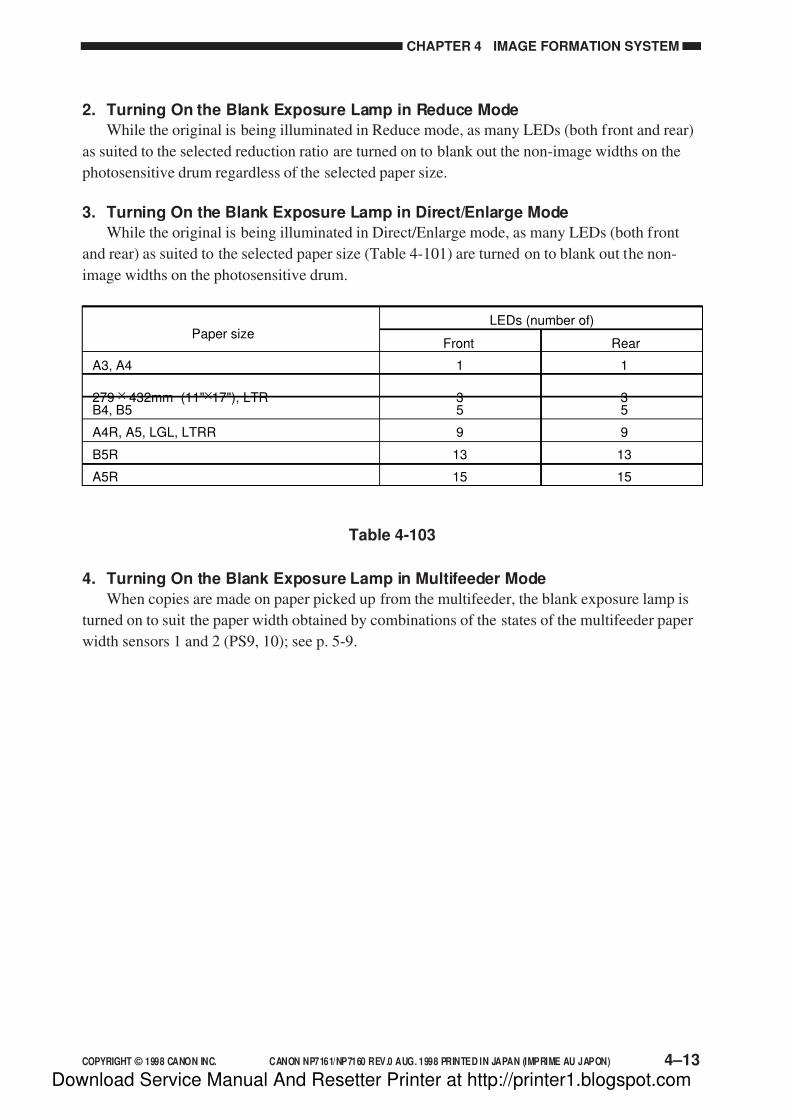
7/16/2019 Canon Np7161-Np7160 Copier Sm
http://slidepdf.com/reader/full/canon-np7161-np7160-copier-sm 91/345
COPYRIGHT © 1998 CANON INC. CANON NP7161/NP7160 REV.0 AUG. 1998 PRINTED IN JAPAN (IMPRIME AU JAPON) 4–13
CHAPTER 4 IMAGE FORMATION SYSTEM
2. Turning On the Blank Exposure Lamp in Reduce Mode
While the original is being illuminated in Reduce mode, as many LEDs (both front and rear)
as suited to the selected reduction ratio are turned on to blank out the non-image widths on the
photosensitive drum regardless of the selected paper size.
3. Turning On the Blank Exposure Lamp in Direct/Enlarge Mode
While the original is being illuminated in Direct/Enlarge mode, as many LEDs (both front
and rear) as suited to the selected paper size (Table 4-101) are turned on to blank out the non-
image widths on the photosensitive drum.
Table 4-103
4. Turning On the Blank Exposure Lamp in Multifeeder Mode
When copies are made on paper picked up from the multifeeder, the blank exposure lamp is
turned on to suit the paper width obtained by combinations of the states of the multifeeder paper
width sensors 1 and 2 (PS9, 10); see p. 5-9.
Paper size
A3, A4
279 × 432mm (11"×17"), LTRB4, B5
A4R, A5, LGL, LTRR
B5R
A5R
1
35
9
13
15
1
35
9
13
15
LEDs (number of)
Front Rear
Download Service Manual And Resetter Printer at http://printer1.blogspot.com
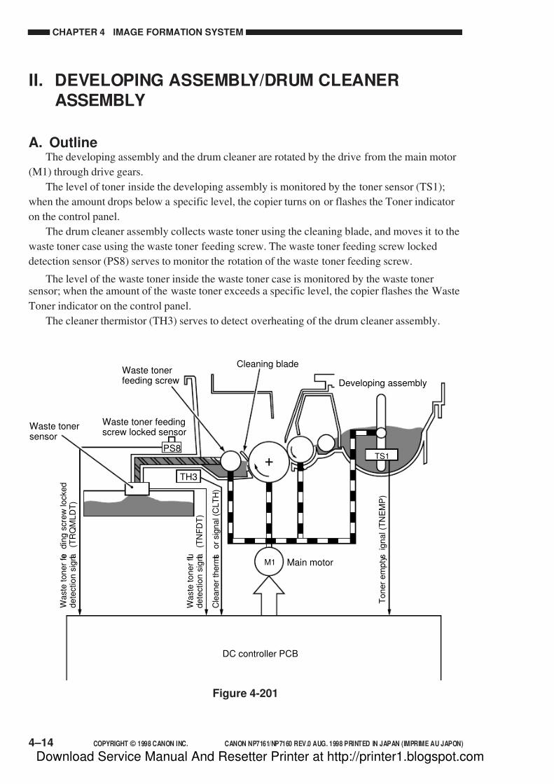
7/16/2019 Canon Np7161-Np7160 Copier Sm
http://slidepdf.com/reader/full/canon-np7161-np7160-copier-sm 92/345
CHAPTER 4 IMAGE FORMATION SYSTEM
4–14 COPYRIGHT © 1998 CANON INC. CANON NP7161/NP7160 REV.0 AUG. 1998 PRINTED IN JAPAN (IMPRIME AU JAPON)
II. DEVELOPING ASSEMBLY/DRUM CLEANERASSEMBLY
A. OutlineThe developing assembly and the drum cleaner are rotated by the drive from the main motor
(M1) through drive gears.
The level of toner inside the developing assembly is monitored by the toner sensor (TS1);
when the amount drops below a specific level, the copier turns on or flashes the Toner indicator
on the control panel.
The drum cleaner assembly collects waste toner using the cleaning blade, and moves it to the
waste toner case using the waste toner feeding screw. The waste toner feeding screw locked
detection sensor (PS8) serves to monitor the rotation of the waste toner feeding screw.
The level of the waste toner inside the waste toner case is monitored by the waste tonersensor; when the amount of the waste toner exceeds a specific level, the copier flashes the Waste
Toner indicator on the control panel.
The cleaner thermistor (TH3) serves to detect overheating of the drum cleaner assembly.
Figure 4-201
TS1
Waste tonersensor
Waste tonerfeeding screw
Waste toner feedingscrew locked sensor
Cleaning blade
DC controller PCB
Main motor
Developing assembly
M1
W a s t e t o n e r f e e d i n g s c r e w l o c k e d
d e t e c t i o n s i g n a l
( T R Q M L D T )
W a s t e t o n e r f u l l
d e t e c t i o n s i g n a l
( T N F D T )
C l e a n e r t h e r m i s t o r s i g n a l ( C L T H )
T o n e r e m p t y s i g n a l ( T N E M P )
PS8
TH3
Download Service Manual And Resetter Printer at http://printer1.blogspot.com

7/16/2019 Canon Np7161-Np7160 Copier Sm
http://slidepdf.com/reader/full/canon-np7161-np7160-copier-sm 93/345
COPYRIGHT © 1998 CANON INC. CANON NP7161/NP7160 REV.0 AUG. 1998 PRINTED IN JAPAN (IMPRIME AU JAPON) 4–15
CHAPTER 4 IMAGE FORMATION SYSTEM
The copier is designed to collect more waste toner than existing models, and is equipped with
a paddle at the bottom of the waste toner box.
The paddle is linked to the movement of the cassette, and is designed to tap on the bottom of
the waste toner box to even out the toner inside it.
Paddle
Paddle
Paddle
Waste toner assembly
Waste tonerassembly
Cassette
Waste tonerassembly
Figure 4-202
Download Service Manual And Resetter Printer at http://printer1.blogspot.com

7/16/2019 Canon Np7161-Np7160 Copier Sm
http://slidepdf.com/reader/full/canon-np7161-np7160-copier-sm 94/345
CHAPTER 4 IMAGE FORMATION SYSTEM
4–16 COPYRIGHT © 1998 CANON INC. CANON NP7161/NP7160 REV.0 AUG. 1998 PRINTED IN JAPAN (IMPRIME AU JAPON)
B. Detecting and Controlling the Level of Toner
The toner inside the developing assembly is monitored by the toner sensor (TS1).
The toner sensor uses a piezoelectric oscillator which oscillates in the absence of toner over
the sensor at several kHz and sends an oscillation signal (TNEMP) to the DC controller PCB. Inthe presence of toner over the sensor, on the other hand, the weight will prevent oscillation.
Figure 4-203
The copier detects the absence of toner in two stages.
The DC controller PCB monitors the output of the toner sensor at all times as long as the
main motor is rotating. If the sum of periods of the toner absent signal is 70 sec (consecutive two
periods), it will identify the condition as a condition preceding the absence of toner and will flash
the Toner indicator on the control panel.
Thereafter, if the period of the toner absent signal reaches 180 sec or more, the DC controller
PCB will assume the condition to be the absence of toner, and will stop flashing the Toner
indicator to keep it on. At this time, the copy being made is processed as would a normal copy
and discharged, and then the operation will be stopped.
Figure 4-204
Table 4-201
Note:
When the DC controller identifies a condition preceding the absence of toner, there is
likely to be as much as 10 g of toner inside the developing assembly. In terms of A4copies, about 200 copies may be made without the addition of toner.
Sequence
Toner sensor (TS1)
Toner absent
T1 T2 T1 T2 T1
AMP
Piezoelectric oscillator
Integrationcircuit
OutputTNEMP
(T1+T2) or (T2+T1) 70sec
T1 or T2 180sec
Conditions Copying
Possible
No possible
Toner indication
Flashing
On =>
=>
Download Service Manual And Resetter Printer at http://printer1.blogspot.com
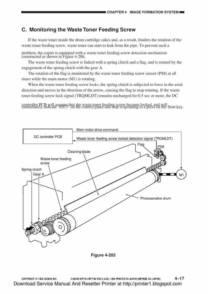
7/16/2019 Canon Np7161-Np7160 Copier Sm
http://slidepdf.com/reader/full/canon-np7161-np7160-copier-sm 95/345
COPYRIGHT © 1998 CANON INC. CANON NP7161/NP7160 REV.0 AUG. 1998 PRINTED IN JAPAN (IMPRIME AU JAPON) 4–17
CHAPTER 4 IMAGE FORMATION SYSTEM
Figure 4-205
DC controller PCB
Cleaning blade
Waste toner feedingscrew
Photosensitve drum
FlagPS8
Waste toner feeding screw locked detection signal (TRQMLDT)
Main motor drive command
Gear A M1
Spring clutch
C. Monitoring the Waste Toner Feeding Screw
If the waste toner inside the drum cartridge cakes and, as a result, hinders the rotation of the
waste toner feeding screw, waste toner can start to leak from the pipe. To prevent such a
problem, the copier is equipped with a waste toner feeding screw detection mechanismconstructed as shown in Figure 4-206.
The waste toner feeding screw is linked with a spring clutch and a flag, and is rotated by the
engagement of the spring clutch with the gear A.
The rotation of the flag is monitored by the waste toner feeding screw sensor (PS8) at all
times while the main motor (M1) is rotating.
When the waste toner feeding screw locks, the spring clutch is subjected to force in the axial
direction and moves in the direction of the arrow, causing the flag to stop rotating. If the waste
toner feeding screw lock signal (TRQMLDT) remains unchanged for 0.5 sec or more, the DC
controller PCB will assume that the waste toner feeding screw became locked, and willimmediately indicate ‘E013’ on the control panel and stop responding to a press on the Start key.
Download Service Manual And Resetter Printer at http://printer1.blogspot.com

7/16/2019 Canon Np7161-Np7160 Copier Sm
http://slidepdf.com/reader/full/canon-np7161-np7160-copier-sm 96/345
CHAPTER 4 IMAGE FORMATION SYSTEM
4–18 COPYRIGHT © 1998 CANON INC. CANON NP7161/NP7160 REV.0 AUG. 1998 PRINTED IN JAPAN (IMPRIME AU JAPON)
Figure 4-206
DC controllerPCB
Referencevoltagecircuit T
N F D T
PowersupplyPCB
HVT
J106
-9
+5VJ303
-1
-2
-3
J301
-1
J210
-10
J212
-16
Waste toner sensor(light-emitting unit)
Waste toner box
Waste toner sensor(light-receiving unit)
Light-blocking plate
Stopper
Comparator circuit
D. Monitoring the Waste Toner Box
The copier monitors the waste toner box in two levels.
The amount of waste toner inside the waste toner box is checked by the waste toner sensor.
The waste toner sensor is a pair of photosensors (light-emitting cell and light-receiving cell), andis designed to generate the waste toner full detection signal (TNFDT) when waste toner blocks
the light between the two photosensors.
The DC controller PCB monitors the state of the waste toner sensor at all times; when the
voltage of the waste toner full detection signal (TNFDT) drops below the reference voltage, it
will identify the condition as “pre-waste toner full condition” and will flash the Waste Toner
indicator on the control panel.
When the waste toner box is not set, the light-blocking plate blocks the light between the
photosensors, causing the copier to flash the Waste Toner indicator.
Download Service Manual And Resetter Printer at http://printer1.blogspot.com

7/16/2019 Canon Np7161-Np7160 Copier Sm
http://slidepdf.com/reader/full/canon-np7161-np7160-copier-sm 97/345
COPYRIGHT © 1998 CANON INC. CANON NP7161/NP7160 REV.0 AUG. 1998 PRINTED IN JAPAN (IMPRIME AU JAPON) 4–19
CHAPTER 4 IMAGE FORMATION SYSTEM
When as many as 100 copies (A4) have been made during a pre-waste toner full condition,
the DC controller PCB will identify the condition as “waste toner full,” stopping to flash the
Waste Toner indicator and instead keeping it on. The copier will not accept the Start key while
the Waste Toner indicator remains on.
Reference:
If the DC controller PCB identifies a waste toner full condition during continuous copying,
the copier will discharge copies being processed and turn on the Waste Toner indicator.
Download Service Manual And Resetter Printer at http://printer1.blogspot.com
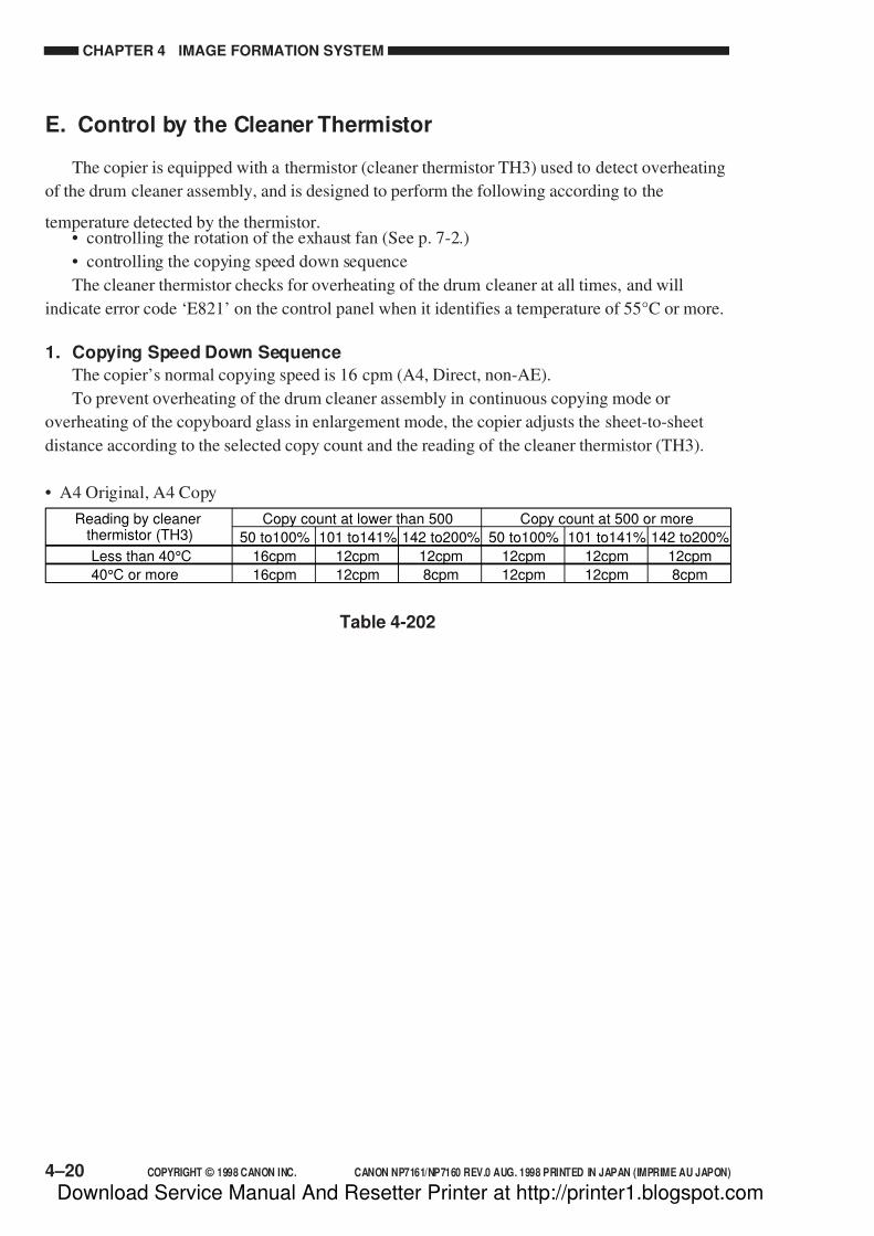
7/16/2019 Canon Np7161-Np7160 Copier Sm
http://slidepdf.com/reader/full/canon-np7161-np7160-copier-sm 98/345
CHAPTER 4 IMAGE FORMATION SYSTEM
4–20 COPYRIGHT © 1998 CANON INC. CANON NP7161/NP7160 REV.0 AUG. 1998 PRINTED IN JAPAN (IMPRIME AU JAPON)
Table 4-202
E. Control by the Cleaner Thermistor
The copier is equipped with a thermistor (cleaner thermistor TH3) used to detect overheating
of the drum cleaner assembly, and is designed to perform the following according to the
temperature detected by the thermistor.• controlling the rotation of the exhaust fan (See p. 7-2.)
• controlling the copying speed down sequence
The cleaner thermistor checks for overheating of the drum cleaner at all times, and will
indicate error code ‘E821’ on the control panel when it identifies a temperature of 55°C or more.
1. Copying Speed Down Sequence
The copier’s normal copying speed is 16 cpm (A4, Direct, non-AE).
To prevent overheating of the drum cleaner assembly in continuous copying mode or
overheating of the copyboard glass in enlargement mode, the copier adjusts the sheet-to-sheet
distance according to the selected copy count and the reading of the cleaner thermistor (TH3).
• A4 Original, A4 Copy
Less than 40°C
Reading by cleanerthermistor (TH3)
40°C or more 16cpm
16cpm
50 to100%
12cpm
12cpm
101 to141%
8cpm
12cpm
142 to200%
12cpm
12cpm
50 to100%
12cpm
12cpm
101 to141%
8cpm
12cpm
142 to200%
Copy count at lower than 500 Copy count at 500 or more
Download Service Manual And Resetter Printer at http://printer1.blogspot.com

7/16/2019 Canon Np7161-Np7160 Copier Sm
http://slidepdf.com/reader/full/canon-np7161-np7160-copier-sm 99/345
COPYRIGHT © 1998 CANON INC. CANON NP7161/NP7160 REV.0 AUG. 1998 PRINTED IN JAPAN (IMPRIME AU JAPON) 4–21
CHAPTER 4 IMAGE FORMATION SYSTEM
F. Auto Density Adjustment (AE)
1. Outline
The copier is equipped with an automatic density adjustment mechanism (AE), which
controls the developing DC bias to suit the density of originals. As long as the original is of evendensity, the AE mechanism is capable of ensuring copies free of fogging by changing the
developing DC bias to suit the density of the original.
2. Measuring the Density of the Original
In initial rotation state (INTR), the scanning lamp (LA1) is turned on at a specific intensity
and the scanner is moved forward 70 mm to expose the original. When the scanner has stopped,
the light reflected by the area shown in Figure 4-208 (in reference to the original butting
position) is measured by the AE sensor (photodiode), whose output is sent to the DC controller
PCB as the AE sensor output signal (AE_DATA).
Based on the signal, the DC controller PCB computes the optimum level of the developing
DC bias for copying, and sends the result to the high-voltage power supply PCB as the
developing bias control signal (DV_DC_CNT).
Area of AE detection
28 mm (approx.)
56 mm (approx.)Center of image
20 mm(approx.)
70 mm(distance of scanner travel)
Figure 4-208
Download Service Manual And Resetter Printer at http://printer1.blogspot.com

7/16/2019 Canon Np7161-Np7160 Copier Sm
http://slidepdf.com/reader/full/canon-np7161-np7160-copier-sm 100/345
CHAPTER 4 IMAGE FORMATION SYSTEM
4–22 COPYRIGHT © 1998 CANON INC. CANON NP7161/NP7160 REV.0 AUG. 1998 PRINTED IN JAPAN (IMPRIME AU JAPON)
Figure 4-209 shows changes in the developing DC bias in relation to the density of different
originals. If the density of the original is higher (darker) than the Test Sheet and lower (lighter)
than a newspaper, the developing DC bias will vary between F5.0 and F7.5 in terms of Copy
Density lever position.
If the original is lighter than the Test Sheet, copies are made at an F5.0 equivalent (-270 V);if it is darker than a newspaper, on the other hand, copies are made at an F7.5 equivalent (-400
V).
Figure 4-209
Figure 4-210
Density of originalDarkerLighter
Developing bias DC (V)
Test Sheet Newspaper
F5.0 equivalent
F7.5 equivalent
F5.0F7.5
Download Service Manual And Resetter Printer at http://printer1.blogspot.com

7/16/2019 Canon Np7161-Np7160 Copier Sm
http://slidepdf.com/reader/full/canon-np7161-np7160-copier-sm 101/345
COPYRIGHT © 1998 CANON INC. CANON NP7161/NP7160 REV.0 AUG. 1998 PRINTED IN JAPAN (IMPRIME AU JAPON) 4–23
CHAPTER 4 IMAGE FORMATION SYSTEM
III. DISASSEMBLY/ASSEMBLY
The copier may be disassembled and assembled as shown here. Pay attention to the copier's
mechanical characteristics along with the steps for disassembly/assembly.
Important:
1. Turn off the power and disconnect the power plug to ensure safety whenever disassembling/
assembling the copier.
2. Unless otherwise noted, assemble the parts by reversing the steps used to disassemble them.
3. Identify the screws by type (length, diameter) to avoid use in the wrong location.
4. Use a washer where needed. The mounting screws used for the grounding wire and varistor
come with a washer to ensure electric continuity. Do not forget to use these washers.
5. As a rule, do not operate the copier with any of its parts removed.
Download Service Manual And Resetter Printer at http://printer1.blogspot.com

7/16/2019 Canon Np7161-Np7160 Copier Sm
http://slidepdf.com/reader/full/canon-np7161-np7160-copier-sm 102/345
CHAPTER 4 IMAGE FORMATION SYSTEM
4–24 COPYRIGHT © 1998 CANON INC. CANON NP7161/NP7160 REV.0 AUG. 1998 PRINTED IN JAPAN (IMPRIME AU JAPON)
A. Scanning Lamp Assembly
1. Removing the Scanning Lamp
1) Remove the copyboard glass. (See .7-14)
2) Holding the bend [A], pull out the scanneras far as the cut-off [B].
3) Remove the mounting screw [1], and
remove the reflecting cover [2].
[A]
[B]
[B]
Figure 4-301
[1]
[2]
Figure 4-302
Download Service Manual And Resetter Printer at http://printer1.blogspot.com

7/16/2019 Canon Np7161-Np7160 Copier Sm
http://slidepdf.com/reader/full/canon-np7161-np7160-copier-sm 103/345
COPYRIGHT © 1998 CANON INC. CANON NP7161/NP7160 REV.0 AUG. 1998 PRINTED IN JAPAN (IMPRIME AU JAPON) 4–25
CHAPTER 4 IMAGE FORMATION SYSTEM
4) Wrap both ends of the scanning lamp [3]
with lint-free paper. Then, remove the
lamp while pushing toward the rear end.
Caution:1. Do not work if the surface of the
scanning lamp is hot.
2. Do not leave fingerprints on the
surface of the scanning lamp.
3. If the surface of the scanning lamp
is soiled, dry wipe it.
4. Do not leave fingerprints on the
reflecting cover.
5. Do not deform the reflecting cover.
2. Mounting the Scanning Lamp
Mount the scanning lamp by reversing the
steps used to remove it. However, keep the
following in mind:
• Orient the scanning lamp so that the
side with the shorter boss-to-terminal
length is toward the rear.
• Orient the scanning lamp so that the
boss is at the angle indicated in Figure
4-304.
3. Removing the Thermal Fuse
1) Remove the scanning lamp.
2) Remove the two mounting screws[1], and
remove the thermal fuse [2].
Caution:
Mount the thermal fuse by reversing
the steps used to remove it. Be careful
of the orientation of the fuse.
Figure 4-304
45˚
[3]
Figure 4-303
Figure 4-305
[2]
[1]
Download Service Manual And Resetter Printer at http://printer1.blogspot.com

7/16/2019 Canon Np7161-Np7160 Copier Sm
http://slidepdf.com/reader/full/canon-np7161-np7160-copier-sm 104/345
CHAPTER 4 IMAGE FORMATION SYSTEM
4–26 COPYRIGHT © 1998 CANON INC. CANON NP7161/NP7160 REV.0 AUG. 1998 PRINTED IN JAPAN (IMPRIME AU JAPON)
B. Exposure Assembly
1. Removing the Pre-Exposure/BlankExposure Lamp Assembly
1) Remove the developing assembly. (See
p.4-37)
2) Remove the drum unit. (See p.4-28)
3) Remove the inside over.
4) Disconnect the two connectors [1], and
remove the mounting screw [2] ; then,
remove the pre-exposure/blank exposure
lamp assembly [3].
2. Removing the Dust-Proofing Glass
1) Remove the inside cover.
2) Remove the mounting screws [1], and
remove the dust-proofing glass [2].
[1]
[2][3]
Figure 4-306
[1] [2]
Figure 4-307
Download Service Manual And Resetter Printer at http://printer1.blogspot.com

7/16/2019 Canon Np7161-Np7160 Copier Sm
http://slidepdf.com/reader/full/canon-np7161-np7160-copier-sm 105/345
COPYRIGHT © 1998 CANON INC. CANON NP7161/NP7160 REV.0 AUG. 1998 PRINTED IN JAPAN (IMPRIME AU JAPON) 4–27
CHAPTER 4 IMAGE FORMATION SYSTEM
[1]
[2]
[3]
Figure 4-308
Figure 4-309
3. Cleaning the No. 6 Mirror
1) Remove the developing assembly. (See p.
4-37.)
2) Remove the drum unit. (See p. 4-28.)
3) Remove the dust-proofing glass. (See p.4-26.)
4) Remove the mounting screw [1], and
remove the developing assembly rail [2].
5) Clean the No. 6 mirror [3].
Download Service Manual And Resetter Printer at http://printer1.blogspot.com

7/16/2019 Canon Np7161-Np7160 Copier Sm
http://slidepdf.com/reader/full/canon-np7161-np7160-copier-sm 106/345
CHAPTER 4 IMAGE FORMATION SYSTEM
4–28 COPYRIGHT © 1998 CANON INC. CANON NP7161/NP7160 REV.0 AUG. 1998 PRINTED IN JAPAN (IMPRIME AU JAPON)
C. Drum Unit
1. Removing the Drum Unit
1) Open the top unit, release the developing
assembly.2) Remove the thumb screw [1], and slide
out the drum unit [2] to the front to remove.
Caution:
• The photosensitive drum is
susceptible to strong light. If it was
subjected to strong light for a long
time, it can cause copies to have
white spots or black lines.
Whenever you have taken out the
drum unit from the copier, be sure to
keep it in the bag used at time of
installation. If the bag is not at hand,
substitute several sheets of fresh
copy paper to wrap the drum unit,
and keep it in a dark place.
• When mounting the drum unit to the
copier, be sure to slide it along the
rails and work with extra care.
[1][2]
Figure 4-310
Download Service Manual And Resetter Printer at http://printer1.blogspot.com

7/16/2019 Canon Np7161-Np7160 Copier Sm
http://slidepdf.com/reader/full/canon-np7161-np7160-copier-sm 107/345
COPYRIGHT © 1998 CANON INC. CANON NP7161/NP7160 REV.0 AUG. 1998 PRINTED IN JAPAN (IMPRIME AU JAPON) 4–29
CHAPTER 4 IMAGE FORMATION SYSTEM
2. Cleaning the Photosensitive Drum
If the surface of the photosensitive drum
is soiled, wipe it with a flannel cloth coated
with toner.
Caution:
• Do not dry wipe the surface of the
photosensitive drum. Do not use
solvent.
• Do not use paper, lint-free or
otherwise, to avoid damaging the
surface of the photosensitive drum.
• Work briskly when cleaning the
photosensitive drum to avoid
unnecessarily subjecting it to light
and thus affecting images.
• If you must rotate the photosensitive
drum, be sure to rotate it in the same
direction as it would when making
copies.
[2]
[3][1]
Figure 4-311
3. Removing the Cleaner Thermistor1) Remove the drum unit. (See p. 4-28.)
2) Remove the fixing assembly. (See p. 6-8.)
3) Disconnect the connector [1], and remove
the mounting screw [2]; then, remove the
cleaner thermistor [3].
Download Service Manual And Resetter Printer at http://printer1.blogspot.com
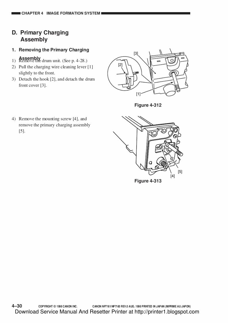
7/16/2019 Canon Np7161-Np7160 Copier Sm
http://slidepdf.com/reader/full/canon-np7161-np7160-copier-sm 108/345
CHAPTER 4 IMAGE FORMATION SYSTEM
4–30 COPYRIGHT © 1998 CANON INC. CANON NP7161/NP7160 REV.0 AUG. 1998 PRINTED IN JAPAN (IMPRIME AU JAPON)
[3]
[1]
[2]
Figure 4-312
[4][5]
Figure 4-313
D. Primary ChargingAssembly
1. Removing the Primary Charging
Assembly1) Remove the drum unit. (See p. 4-28.)
2) Pull the charging wire cleaning lever [1]
slightly to the front.
3) Detach the hook [2], and detach the drum
front cover [3].
4) Remove the mounting screw [4], and
remove the primary charging assembly
[5].
Download Service Manual And Resetter Printer at http://printer1.blogspot.com

7/16/2019 Canon Np7161-Np7160 Copier Sm
http://slidepdf.com/reader/full/canon-np7161-np7160-copier-sm 109/345
COPYRIGHT © 1998 CANON INC. CANON NP7161/NP7160 REV.0 AUG. 1998 PRINTED IN JAPAN (IMPRIME AU JAPON) 4–31
CHAPTER 4 IMAGE FORMATION SYSTEM
[2] [3][1]
[4]
Figure 4-314
E. Transfer ChargingAssembly
1. Removing the Transfer Charging
Assembly1) Open the copier top, and remove the front
door.
2) Pull the charging wire cleaning lever [1]
slightly to the front.
3) Remove the mounting screw [2], and lift
the stopper [3] to remove.
4) Pull the transfer charging assembly [4] to
the front to remove.
Download Service Manual And Resetter Printer at http://printer1.blogspot.com
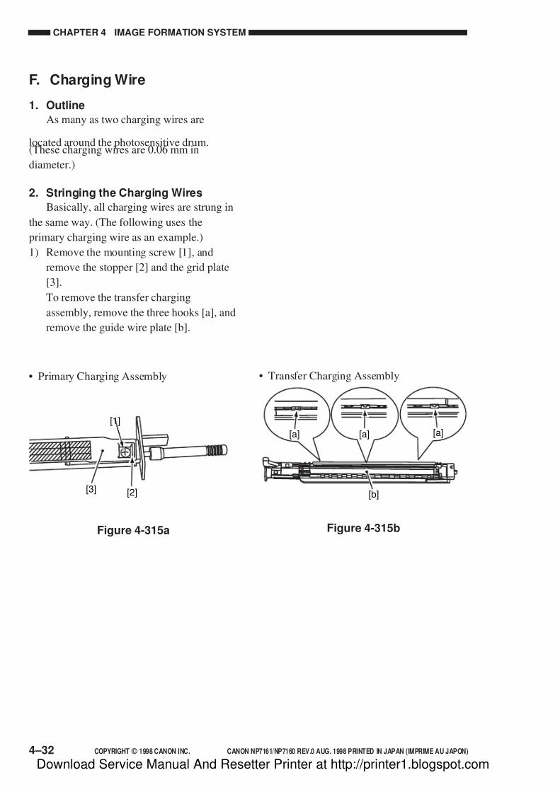
7/16/2019 Canon Np7161-Np7160 Copier Sm
http://slidepdf.com/reader/full/canon-np7161-np7160-copier-sm 110/345
CHAPTER 4 IMAGE FORMATION SYSTEM
4–32 COPYRIGHT © 1998 CANON INC. CANON NP7161/NP7160 REV.0 AUG. 1998 PRINTED IN JAPAN (IMPRIME AU JAPON)
F. Charging Wire
1. Outline
As many as two charging wires are
located around the photosensitive drum.(These charging wires are 0.06 mm in
diameter.)
2. Stringing the Charging Wires
Basically, all charging wires are strung in
the same way. (The following uses the
primary charging wire as an example.)
1) Remove the mounting screw [1], and
remove the stopper [2] and the grid plate
[3].
To remove the transfer charging
assembly, remove the three hooks [a], and
remove the guide wire plate [b].
• Transfer Charging Assembly
Figure 4-315b
[a] [a][a]
[b]
• Primary Charging Assembly
Figure 4-315a
[1]
[2][3]
Download Service Manual And Resetter Printer at http://printer1.blogspot.com
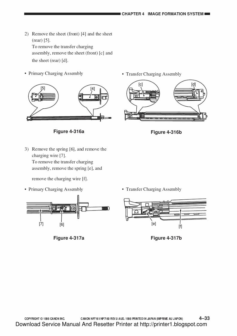
7/16/2019 Canon Np7161-Np7160 Copier Sm
http://slidepdf.com/reader/full/canon-np7161-np7160-copier-sm 111/345
COPYRIGHT © 1998 CANON INC. CANON NP7161/NP7160 REV.0 AUG. 1998 PRINTED IN JAPAN (IMPRIME AU JAPON) 4–33
CHAPTER 4 IMAGE FORMATION SYSTEM
2) Remove the sheet (front) [4] and the sheet
(rear) [5].
To remove the transfer charging
assembly, remove the sheet (front) [c] and
the sheet (rear) [d].
3) Remove the spring [6], and remove the
charging wire [7].
To remove the transfer charging
assembly, remove the spring [e], and
remove the charging wire [f].
• Primary Charging Assembly
Figure 4-316a
• Transfer Charging Assembly
Figure 4-316b
[c] [d]
• Primary Charging Assembly
Figure 4-317a
• Transfer Charging Assembly
Figure 4-317b
[f][e]
[4][5]
[6][7]
Download Service Manual And Resetter Printer at http://printer1.blogspot.com
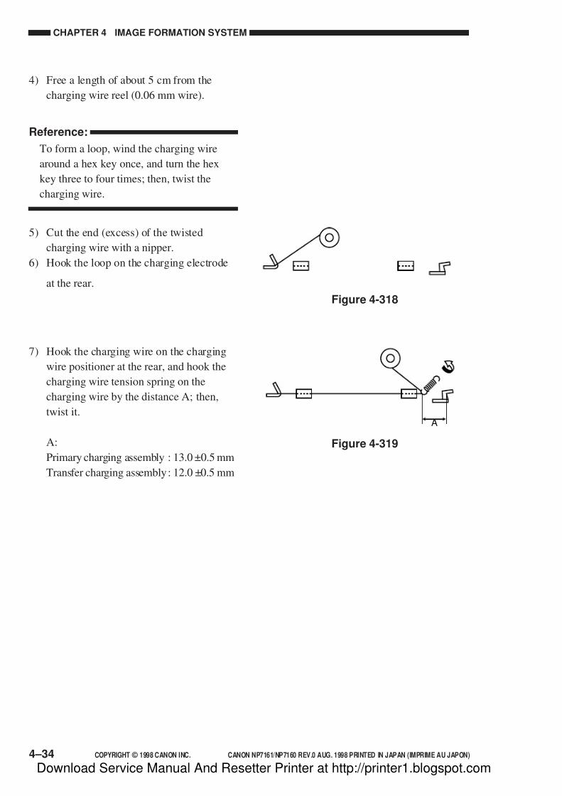
7/16/2019 Canon Np7161-Np7160 Copier Sm
http://slidepdf.com/reader/full/canon-np7161-np7160-copier-sm 112/345
CHAPTER 4 IMAGE FORMATION SYSTEM
4–34 COPYRIGHT © 1998 CANON INC. CANON NP7161/NP7160 REV.0 AUG. 1998 PRINTED IN JAPAN (IMPRIME AU JAPON)
Figure 4-318
A
Figure 4-319
4) Free a length of about 5 cm from the
charging wire reel (0.06 mm wire).
Reference:
To form a loop, wind the charging wire
around a hex key once, and turn the hex
key three to four times; then, twist the
charging wire.
5) Cut the end (excess) of the twisted
charging wire with a nipper.
6) Hook the loop on the charging electrode
at the rear.
7) Hook the charging wire on the charging
wire positioner at the rear, and hook the
charging wire tension spring on the
charging wire by the distance A; then,
twist it.
A:
Primary charging assembly : 13.0 ±0.5 mm
Transfer charging assembly: 12.0 ±0.5 mm
Download Service Manual And Resetter Printer at http://printer1.blogspot.com

7/16/2019 Canon Np7161-Np7160 Copier Sm
http://slidepdf.com/reader/full/canon-np7161-np7160-copier-sm 113/345
COPYRIGHT © 1998 CANON INC. CANON NP7161/NP7160 REV.0 AUG. 1998 PRINTED IN JAPAN (IMPRIME AU JAPON) 4–35
CHAPTER 4 IMAGE FORMATION SYSTEM
8) Cut the excess charging wire with a
nipper.
9) Pick the end of the charging wire
tensioning spring with tweezers, and hook
it on the charging electrode.
Note:
Go through the following:• Be sure that the charging wire is free
of bending and twisting, and its gold
plating has not peeled.
• Be sure that the charging wire is in
the V-groove of the charging wire
positioner.
10) Wipe the charging wire with lint-free
paper moistened with alcohol.
Caution:
• Do not use a cloth carrying metal
powder for cleaning.
• Do not use a moist cloth for
cleaning.
• Dry wipe with lint-free paper; then,
mount only after making sure that
alcohol has completely evaporated.
11) Mount the sheet (front) and the sheet
(rear).
12) Mount the stopper and the grid plate.
For the transfer charging assembly, mount
the guide wire plate.
Figure 4-320
Figure 4-321
(correct) (wrong)
Download Service Manual And Resetter Printer at http://printer1.blogspot.com

7/16/2019 Canon Np7161-Np7160 Copier Sm
http://slidepdf.com/reader/full/canon-np7161-np7160-copier-sm 114/345
CHAPTER 4 IMAGE FORMATION SYSTEM
4–36 COPYRIGHT © 1998 CANON INC. CANON NP7161/NP7160 REV.0 AUG. 1998 PRINTED IN JAPAN (IMPRIME AU JAPON)
3. Adjusting the Height of theCharging Wires
To adjust each charging wire, turn its
respective height adjusting screw. A full turn
on the screw will change the height of theprimary charging wire by about 0.5 mm and
that of the transfer charging wire by about 0.7
mm.
Figure 4-322
• Transfer Charging Assembly
Figure 4-323b
• Primary Charging Assembly
Figure 4-323a
Height adjustingscrew
Height adjustingscrew
Height adjustingscrew
Height adjustingscrew
Chargingassembly
Height of chargingwire (mm)
Range
Primary 1.0mm11.0 0.2mm
9.5 0.2mmTransfer 1.0mm
Download Service Manual And Resetter Printer at http://printer1.blogspot.com

7/16/2019 Canon Np7161-Np7160 Copier Sm
http://slidepdf.com/reader/full/canon-np7161-np7160-copier-sm 115/345
COPYRIGHT © 1998 CANON INC. CANON NP7161/NP7160 REV.0 AUG. 1998 PRINTED IN JAPAN (IMPRIME AU JAPON) 4–37
CHAPTER 4 IMAGE FORMATION SYSTEM
[2] [1] [3]
Figure 4-324
G. Developing Assembly
1. Removing the DevelopingAssembly
1) Open the front door, and release the
developing assembly.
2) Remove the mounting screw [1], and
remove the stopper [2].
3) Pull the developing assembly [3] to
remove.
Caution:
Take care not to damage the
developing cylinder.
2. Removing the Developing Blade
1) Remove the developing assembly.
2) Remove the mounting screw [1] and the
three hooks [2]; then, remove the
developing front cover [3].
[1]
[2]
[3]
3) Remove the three mounting screws [4],
and detach the developing blade cover [5].
[5]
[4]
Figure 4-325
Figure 4-326
Download Service Manual And Resetter Printer at http://printer1.blogspot.com
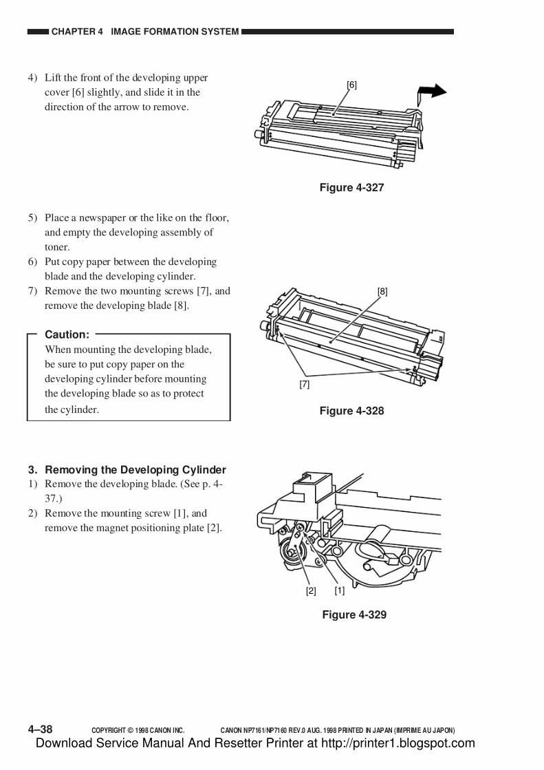
7/16/2019 Canon Np7161-Np7160 Copier Sm
http://slidepdf.com/reader/full/canon-np7161-np7160-copier-sm 116/345
CHAPTER 4 IMAGE FORMATION SYSTEM
4–38 COPYRIGHT © 1998 CANON INC. CANON NP7161/NP7160 REV.0 AUG. 1998 PRINTED IN JAPAN (IMPRIME AU JAPON)
4) Lift the front of the developing upper
cover [6] slightly, and slide it in the
direction of the arrow to remove.
[6]
Figure 4-327
[8]
[7]
[2] [1]
Figure 4-328
Figure 4-329
5) Place a newspaper or the like on the floor,
and empty the developing assembly of
toner.
6) Put copy paper between the developing
blade and the developing cylinder.
7) Remove the two mounting screws [7], and
remove the developing blade [8].
Caution:
When mounting the developing blade,
be sure to put copy paper on the
developing cylinder before mounting
the developing blade so as to protect
the cylinder.
3. Removing the Developing Cylinder
1) Remove the developing blade. (See p. 4-
37.)
2) Remove the mounting screw [1], and
remove the magnet positioning plate [2].
Download Service Manual And Resetter Printer at http://printer1.blogspot.com
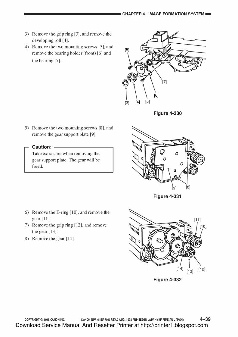
7/16/2019 Canon Np7161-Np7160 Copier Sm
http://slidepdf.com/reader/full/canon-np7161-np7160-copier-sm 117/345
COPYRIGHT © 1998 CANON INC. CANON NP7161/NP7160 REV.0 AUG. 1998 PRINTED IN JAPAN (IMPRIME AU JAPON) 4–39
CHAPTER 4 IMAGE FORMATION SYSTEM
3) Remove the grip ring [3], and remove the
developing roll [4].
4) Remove the two mounting screws [5], and
remove the bearing holder (front) [6] and
the bearing [7].
[3] [4] [5]
[6]
[7]
[5]
Figure 4-330
5) Remove the two mounting screws [8], and
remove the gear support plate [9].
Caution:
Take extra care when removing the
gear support plate. The gear will be
freed.
[9] [8]
Figure 4-331
[14][13]
[12]
[10]
[11]
Figure 4-332
6) Remove the E-ring [10], and remove the
gear [11].
7) Remove the grip ring [12], and remove
the gear [13].
8) Remove the gear [14].
Download Service Manual And Resetter Printer at http://printer1.blogspot.com

7/16/2019 Canon Np7161-Np7160 Copier Sm
http://slidepdf.com/reader/full/canon-np7161-np7160-copier-sm 118/345
CHAPTER 4 IMAGE FORMATION SYSTEM
4–40 COPYRIGHT © 1998 CANON INC. CANON NP7161/NP7160 REV.0 AUG. 1998 PRINTED IN JAPAN (IMPRIME AU JAPON)
[15]
[17][18]
[16]
Figure 4-333
9) Remove the two mounting screws [15];
then, remove the bearing holder (rear)
[16], bearing [17], and developing roll
[18].
Figure 4-334
[19]
10) Remove the developing cylinder [19].
Caution
Do not leave fingerprints or oils on
the surface of the developing cylinder.
As necessary, dry wipe the surface
with lint-free paper.
Download Service Manual And Resetter Printer at http://printer1.blogspot.com

7/16/2019 Canon Np7161-Np7160 Copier Sm
http://slidepdf.com/reader/full/canon-np7161-np7160-copier-sm 119/345
COPYRIGHT © 1998 CANON INC. CANON NP7161/NP7160 REV.0 AUG. 1998 PRINTED IN JAPAN (IMPRIME AU JAPON)
CHAPTER 5
PICK-UP/FEEDING SYSTEM
This chapter explains the principles used from when copy paper is picked up to when a copy is delivered
in view of the functions of electrical and mechanical units and in relation to their timing of operation. It
also shows how these units may be disassembled/assembled and adjusted.
I. OUTLINE OF OPERATION ..................... 5-1II. PICK-UP FROM THE CASSETTE .......... 5-2
A. Pick-Up Operation .............................. 5-2
B. Sequence of Operations(pick-up/feeding) ................................ 5-3
C. Operation of the Cassette Lifter ......... 5-4
D. Detecting the Size of the Cassette .... 5-6
III. PICK-UP FROM THE MULTIFEEDER .... 5-8
A. Pick-Up Operation .............................. 5-8B. Detecting the Size of Paper
in the Multifeeder ................................ 5-9C. Sequence of Operations
(pick-up from multifeeder) ................ 5-10
IV. CONTROLLING THE REGISTRATIONCLUTCH ................................................. 5-11
V. DETECTING JAMS ................................ 5-12
A. Outline .............................................. 5-12B. Sequence of Operations
(jam detection).................................. 5-13
VI. DISASSEMBLY/ASSEMBLY ................. 5-15
A. Pick-Up Assembly ............................ 5-16B. Multifeeder Assembly ....................... 5-20
C. Registration Roller Assembly ........... 5-23
D. Cassette Assembly .......................... 5-24
Download Service Manual And Resetter Printer at http://printer1.blogspot.com

7/16/2019 Canon Np7161-Np7160 Copier Sm
http://slidepdf.com/reader/full/canon-np7161-np7160-copier-sm 120/345
Download Service Manual And Resetter Printer at http://printer1.blogspot.com

7/16/2019 Canon Np7161-Np7160 Copier Sm
http://slidepdf.com/reader/full/canon-np7161-np7160-copier-sm 121/345
COPYRIGHT © 1998 CANON INC. CANON NP7161/NP7160 REV.0 AUG. 1998 PRINTED IN JAPAN (IMPRIME AU JAPON) 5–1
CHAPTER 5 PICK-UP/FEEDING SYSTEM
I. OUTLINE OF OPERATION
The copier uses a center reference feeding method, in which copy paper is moved along the
center of the pick-up/feeding path to ensure stable movement.
The pick-up system consists of the cassette No. 1 holder and the multifeeder. Copy paper
picked up from the cassette or the multifeeder is controlled by the registration roller so that it is
aligned with the leading edge of the image on the photosensitive drum, and is sent through the
transfer, separation, and fixing assemblies and then to the copy tray.
As many as two sensors are used to monitor the movement of the copy paper.
Figure 5-101
Cassette
Registrationroller
Photosensitivedrum
Fixingassembly
Multifeeder
PS6 PS5
Table 5-101
No. Sensor
PS5
PS6
Registration paper sensor
Delivery paper sensor
Description
Detects delay/stationary jams, measures paper length.
Detects delay/stationary jams.
Download Service Manual And Resetter Printer at http://printer1.blogspot.com
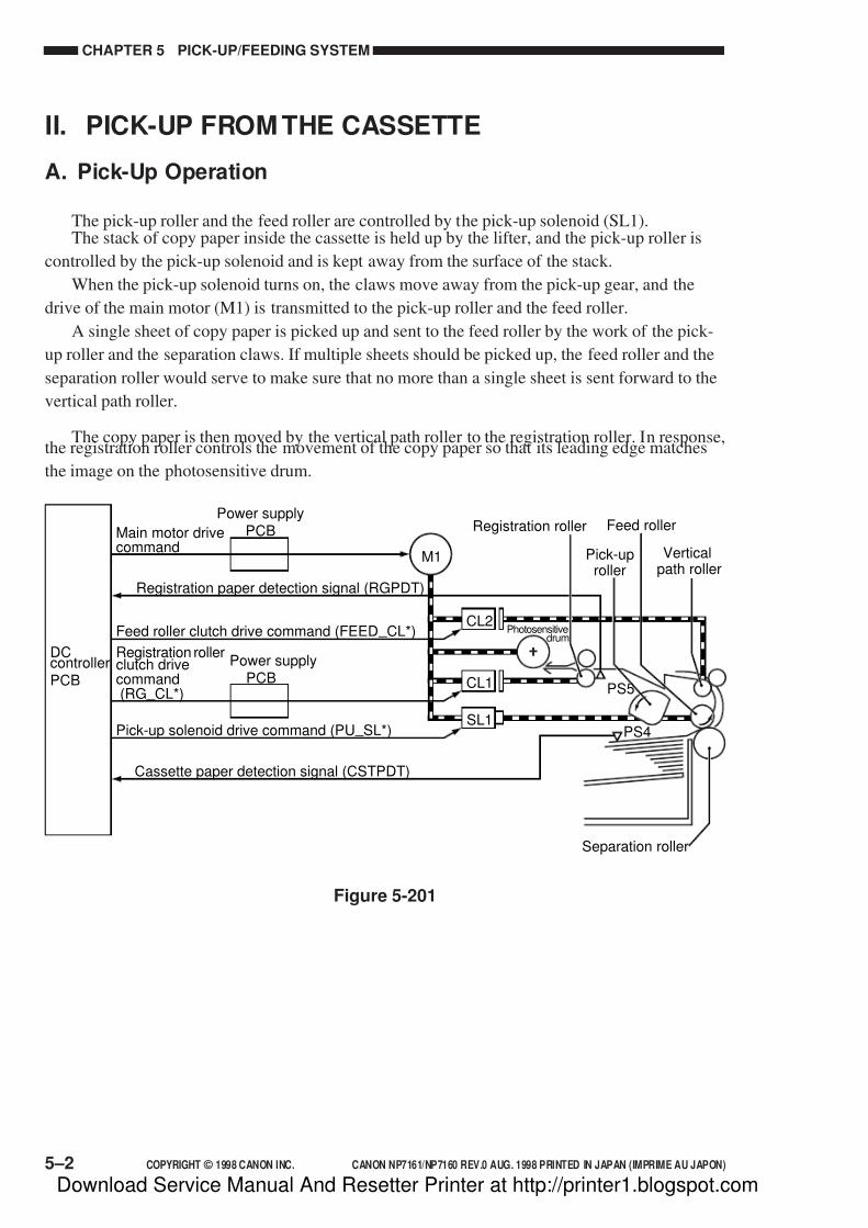
7/16/2019 Canon Np7161-Np7160 Copier Sm
http://slidepdf.com/reader/full/canon-np7161-np7160-copier-sm 122/345
CHAPTER 5 PICK-UP/FEEDING SYSTEM
5–2 COPYRIGHT © 1998 CANON INC. CANON NP7161/NP7160 REV.0 AUG. 1998 PRINTED IN JAPAN (IMPRIME AU JAPON)
II. PICK-UP FROM THE CASSETTE
A. Pick-Up Operation
The pick-up roller and the feed roller are controlled by the pick-up solenoid (SL1).The stack of copy paper inside the cassette is held up by the lifter, and the pick-up roller is
controlled by the pick-up solenoid and is kept away from the surface of the stack.
When the pick-up solenoid turns on, the claws move away from the pick-up gear, and the
drive of the main motor (M1) is transmitted to the pick-up roller and the feed roller.
A single sheet of copy paper is picked up and sent to the feed roller by the work of the pick-
up roller and the separation claws. If multiple sheets should be picked up, the feed roller and the
separation roller would serve to make sure that no more than a single sheet is sent forward to the
vertical path roller.
The copy paper is then moved by the vertical path roller to the registration roller. In response,the registration roller controls the movement of the copy paper so that its leading edge matches
the image on the photosensitive drum.
PS5
PS4
CL1
CL2
SL1
M1
DCcontrollerPCB
Power supplyPCB
Power supplyPCB
Main motor drivecommand
Feed roller clutch drive command (FEED _ CL*)
Registration rollerclutch drivecommand(RG _ CL*)
Pick-up solenoid drive command (PU _ SL*)
Registration paper detection signal (RGPDT)
Cassette paper detection signal (CSTPDT)
Registration roller
Photosensitivedrum
Pick-uproller
Verticalpath roller
Feed roller
Separation roller
Figure 5-201
Download Service Manual And Resetter Printer at http://printer1.blogspot.com
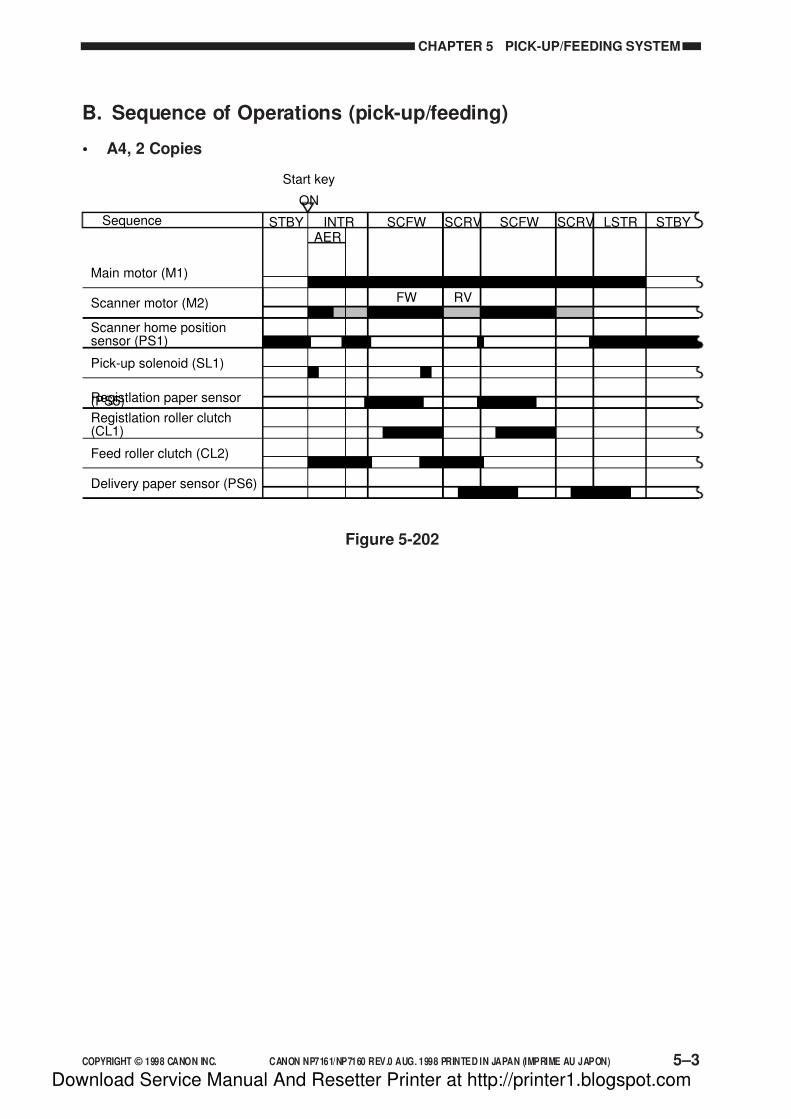
7/16/2019 Canon Np7161-Np7160 Copier Sm
http://slidepdf.com/reader/full/canon-np7161-np7160-copier-sm 123/345
COPYRIGHT © 1998 CANON INC. CANON NP7161/NP7160 REV.0 AUG. 1998 PRINTED IN JAPAN (IMPRIME AU JAPON) 5–3
CHAPTER 5 PICK-UP/FEEDING SYSTEM
B. Sequence of Operations (pick-up/feeding)
• A4, 2 Copies
Figure 5-202
Start key
ON
STBY
FW RV
STBYLSTRSCRVSCFWSCRVSCFWINTRAER
Sequence
Scanner motor (M2)
Scanner home positionsensor (PS1)
Pick-up solenoid (SL1)
Registlation paper sensor(PS5)
Delivery paper sensor (PS6)
Registlation roller clutch(CL1)
Feed roller clutch (CL2)
Main motor (M1)
Download Service Manual And Resetter Printer at http://printer1.blogspot.com
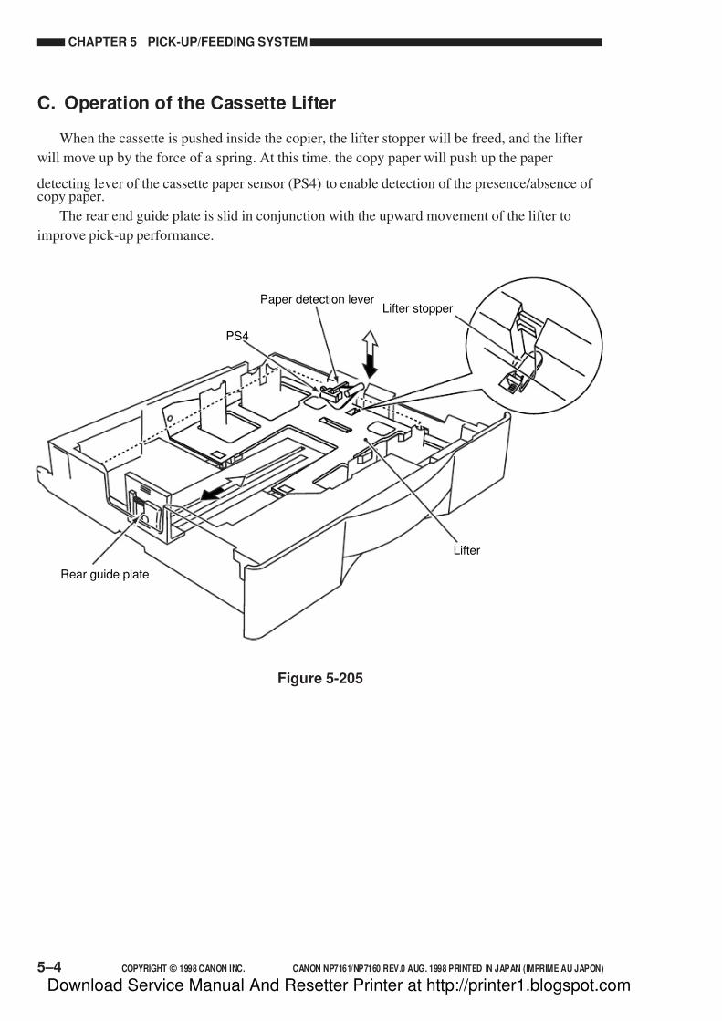
7/16/2019 Canon Np7161-Np7160 Copier Sm
http://slidepdf.com/reader/full/canon-np7161-np7160-copier-sm 124/345
CHAPTER 5 PICK-UP/FEEDING SYSTEM
5–4 COPYRIGHT © 1998 CANON INC. CANON NP7161/NP7160 REV.0 AUG. 1998 PRINTED IN JAPAN (IMPRIME AU JAPON)
C. Operation of the Cassette Lifter
When the cassette is pushed inside the copier, the lifter stopper will be freed, and the lifter
will move up by the force of a spring. At this time, the copy paper will push up the paper
detecting lever of the cassette paper sensor (PS4) to enable detection of the presence/absence of copy paper.
The rear end guide plate is slid in conjunction with the upward movement of the lifter to
improve pick-up performance.
PS4
Rear guide plate
Lifter
Lifter stopperPaper detection lever
Figure 5-205
Download Service Manual And Resetter Printer at http://printer1.blogspot.com
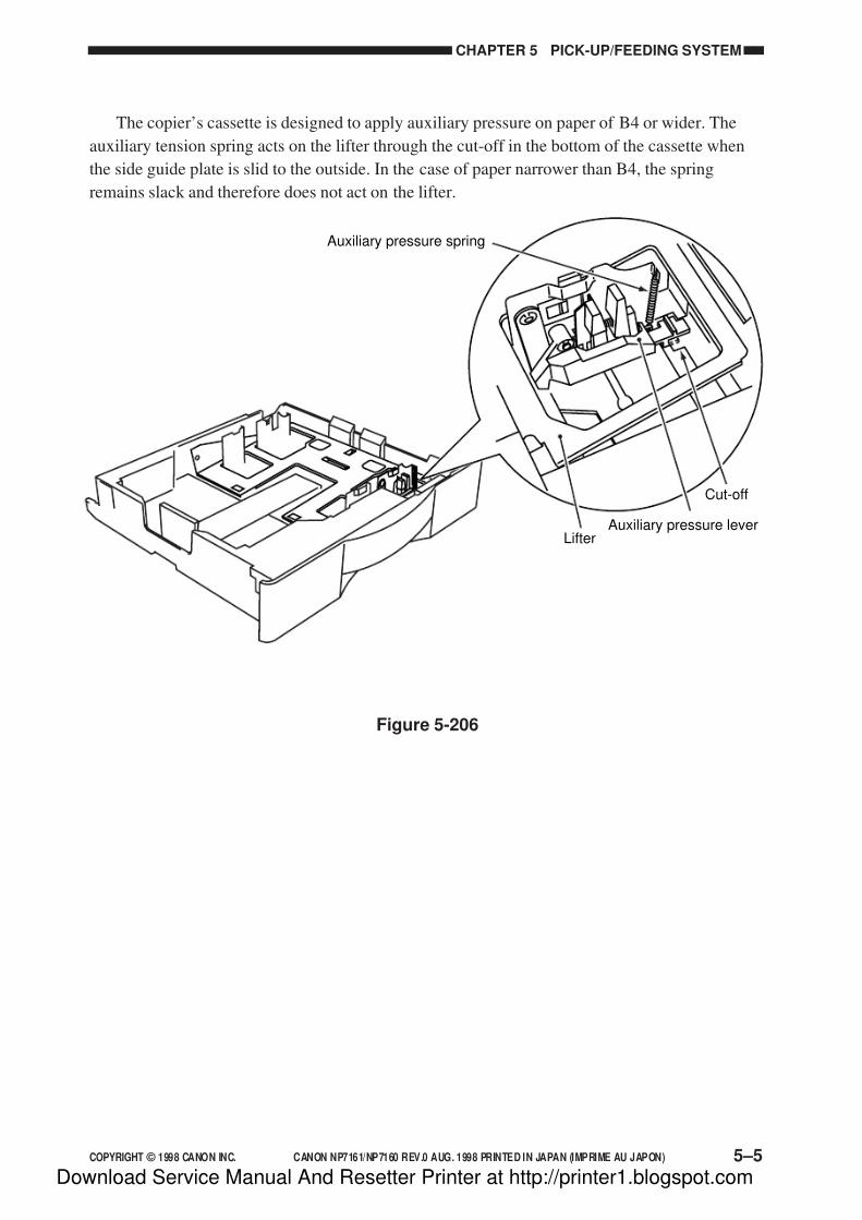
7/16/2019 Canon Np7161-Np7160 Copier Sm
http://slidepdf.com/reader/full/canon-np7161-np7160-copier-sm 125/345
COPYRIGHT © 1998 CANON INC. CANON NP7161/NP7160 REV.0 AUG. 1998 PRINTED IN JAPAN (IMPRIME AU JAPON) 5–5
CHAPTER 5 PICK-UP/FEEDING SYSTEM
The copier’s cassette is designed to apply auxiliary pressure on paper of B4 or wider. The
auxiliary tension spring acts on the lifter through the cut-off in the bottom of the cassette when
the side guide plate is slid to the outside. In the case of paper narrower than B4, the spring
remains slack and therefore does not act on the lifter.
Auxiliary pressure spring
Lifter
Cut-off
Auxiliary pressure lever
Figure 5-206
Download Service Manual And Resetter Printer at http://printer1.blogspot.com
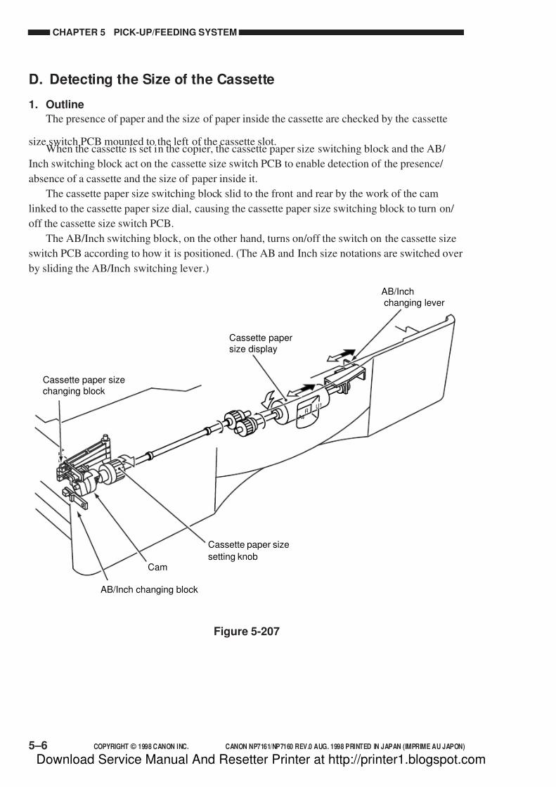
7/16/2019 Canon Np7161-Np7160 Copier Sm
http://slidepdf.com/reader/full/canon-np7161-np7160-copier-sm 126/345
CHAPTER 5 PICK-UP/FEEDING SYSTEM
5–6 COPYRIGHT © 1998 CANON INC. CANON NP7161/NP7160 REV.0 AUG. 1998 PRINTED IN JAPAN (IMPRIME AU JAPON)
D. Detecting the Size of the Cassette
1. Outline
The presence of paper and the size of paper inside the cassette are checked by the cassette
size switch PCB mounted to the left of the cassette slot.When the cassette is set in the copier, the cassette paper size switching block and the AB/
Inch switching block act on the cassette size switch PCB to enable detection of the presence/
absence of a cassette and the size of paper inside it.
The cassette paper size switching block slid to the front and rear by the work of the cam
linked to the cassette paper size dial, causing the cassette paper size switching block to turn on/
off the cassette size switch PCB.
The AB/Inch switching block, on the other hand, turns on/off the switch on the cassette size
switch PCB according to how it is positioned. (The AB and Inch size notations are switched over
by sliding the AB/Inch switching lever.)
Figure 5-207
A4R
U1
Cassette paper size
setting knobCam
Cassette papersize display
Cassette paper sizechanging block
AB/Inch changing block
AB/Inchchanging lever
Download Service Manual And Resetter Printer at http://printer1.blogspot.com
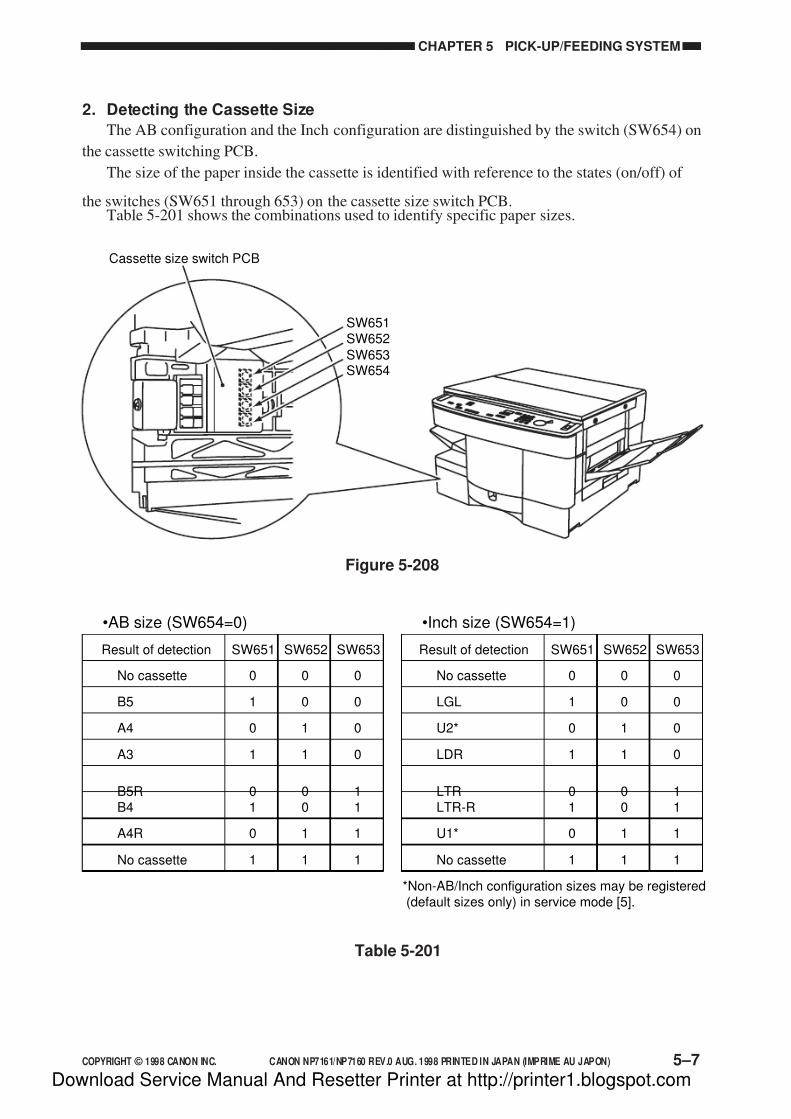
7/16/2019 Canon Np7161-Np7160 Copier Sm
http://slidepdf.com/reader/full/canon-np7161-np7160-copier-sm 127/345
COPYRIGHT © 1998 CANON INC. CANON NP7161/NP7160 REV.0 AUG. 1998 PRINTED IN JAPAN (IMPRIME AU JAPON) 5–7
CHAPTER 5 PICK-UP/FEEDING SYSTEM
2. Detecting the Cassette Size
The AB configuration and the Inch configuration are distinguished by the switch (SW654) on
the cassette switching PCB.
The size of the paper inside the cassette is identified with reference to the states (on/off) of
the switches (SW651 through 653) on the cassette size switch PCB.Table 5-201 shows the combinations used to identify specific paper sizes.
000No cassette
Result of detection
001B5
010A4
011A3
100B5R101B4
110A4R
111No cassette
000No cassette
001LGL
010U2*
011LDR
100LTR101LTR-R
110U1*
111No cassette
*Non-AB/Inch configuration sizes may be registered(default sizes only) in service mode [5].
SW653SW652SW651Result of detection
•AB size (SW654=0) •Inch size (SW654=1)
SW653SW652SW651
Table 5-201
SW652SW651
SW653SW654
Cassette size switch PCB
Figure 5-208
Download Service Manual And Resetter Printer at http://printer1.blogspot.com

7/16/2019 Canon Np7161-Np7160 Copier Sm
http://slidepdf.com/reader/full/canon-np7161-np7160-copier-sm 128/345
CHAPTER 5 PICK-UP/FEEDING SYSTEM
5–8 COPYRIGHT © 1998 CANON INC. CANON NP7161/NP7160 REV.0 AUG. 1998 PRINTED IN JAPAN (IMPRIME AU JAPON)
III. PICK-UP FROM THE MULTIFEEDER
A. Pick-Up Operation
The presence/absence of copy paper in the multifeeder is detected by the multifeeder papersensor (PS7).
When the multifeeder is selected and the Start key is pressed, the multifeeder solenoid (SL2)
turns on to butt the paper guide plate against the multifeeder pick-up roller.
Then, the multifeeder roller clutch (CL3) turns on to transmit the drive of the main motor
(M1) to the multifeeder pick-up roller. A single sheet of copy paper is picked up from the stack
by the work of the multifeeder pick-up roller and the separation pad, and is sent to the
registration roller.
This sequence of operations is repeated for each pick-up operation.
Figure 5-301
Multifeedroller
clutch (CL3)
M a i n m o t o r d r i v e
c o m m a n d
M u l t i f e e d s o l e n o i d
d r i v e c o m m a n d
( M L T
_ S L * )
M u l t i f e e d r o l l e r
c l u t c h d r i v e
c o m m a n d
( M L T
_ C L * )
M u l t i f e e d e r p a p e r
d e t e c t i o n s i g n a l
( M L T P D 0 )
Multifeedsolenoid
(SL2)
Separation pad
Multifeeder papersensor (PS7)
Cam
Multifeed roller
Cam
CL3SL2
Stopper
M1
DC controller PCB
Control ring
Paper guide plate
Paper guideplate
Control ring
Download Service Manual And Resetter Printer at http://printer1.blogspot.com

7/16/2019 Canon Np7161-Np7160 Copier Sm
http://slidepdf.com/reader/full/canon-np7161-np7160-copier-sm 129/345
COPYRIGHT © 1998 CANON INC. CANON NP7161/NP7160 REV.0 AUG. 1998 PRINTED IN JAPAN (IMPRIME AU JAPON) 5–9
CHAPTER 5 PICK-UP/FEEDING SYSTEM
B. Detecting the Size of Paper in the Multifeeder
When the user sets the slide guide of the multifeeder to the width of copy paper, the
multifeeder paper width sensor 1 (PS9) and the multifeeder paper width sensor (PS10) operating
in conjunction with the movement of the side guide detect the width of the copy paper.The identified width is used for blank exposure and fixing temperature control. The length of
copy paper in multifeeder mode is detected with reference to how long the registration paper
sensor (PS5) remains on.
DCcontrollerPCB
Slide guide (rear)
Slide guide (front)Multifeeder tray
PS9
PS10
PS9
PS10
Slide guide (front)
Tape
Multifeeder paper width
detection signal 1 (MLTPD1)
Multifeeder paper width
detection signal 2 (MLTPD2)
Figure 5-302
Table 5-301
Paper width (mm) PS9 PS10
Paper width > 257
257 Paper width > 216
0
1
216 Paper width > 182 1
182 Paper width 0
1
1
0
0
=>
=>
=>
Download Service Manual And Resetter Printer at http://printer1.blogspot.com

7/16/2019 Canon Np7161-Np7160 Copier Sm
http://slidepdf.com/reader/full/canon-np7161-np7160-copier-sm 130/345
CHAPTER 5 PICK-UP/FEEDING SYSTEM
5–10 COPYRIGHT © 1998 CANON INC. CANON NP7161/NP7160 REV.0 AUG. 1998 PRINTED IN JAPAN (IMPRIME AU JAPON)
C. Sequence of Operations (pick-up from multifeeder)
• A4, 2 Copies
Figure 5-303
Start keyON
STBY
FW RV
STBYLSTRSCRVSCFWSCRVSCFWINTRAER
Sequence
Scanner motor (M2)
Scanner home positionsensor (PS1)
Multifeed solenoid (SL2)
Registration paper sensor(PS5)
Delivery paper sensor (PS6)
Registration roller clutch(CL1)
Multifeed roller clutch (CL3)
Main motor (M1)
Download Service Manual And Resetter Printer at http://printer1.blogspot.com

7/16/2019 Canon Np7161-Np7160 Copier Sm
http://slidepdf.com/reader/full/canon-np7161-np7160-copier-sm 131/345
COPYRIGHT © 1998 CANON INC. CANON NP7161/NP7160 REV.0 AUG. 1998 PRINTED IN JAPAN (IMPRIME AU JAPON) 5–11
CHAPTER 5 PICK-UP/FEEDING SYSTEM
IV. CONTROLLING THE REGISTRATION CLUTCH
The registration clutch exerts the following control so as to match copy paper with the image
on the photosensitive drum at a specific location.
Copy paper
B
Copy paper ahead ofimage on drum
Image on drumDrum
Copy paper
A
Copy paper behind imageon drum
Image on drumDrum
Copy paper
Standard copying
Selected copy mode Control timing
A
Page separation A
Fit to page
CenteringOFF
CenteringON
The size of marginC varies to suit theselected reproduction
ratio and copy papersize. The size of marginD is 21.6 mm maximum.
A
B
Image area on copy paper Remarks
Image area
D C-D
C
Figure 5-401
If centering is turned on in Fit Page mode, control is exerted so that half of the trailing edge
C resulting in relation to the selected reproduction ratio and copy paper size will be the leading
edge margin. The maximum leading edge margin in such cases, however, is 21.6 mm.
If centering is turned off in Fit Page mode, control is exerted so that the leading edge of copy
paper and the leading edge of the image on the photosensitive drum match.
Download Service Manual And Resetter Printer at http://printer1.blogspot.com

7/16/2019 Canon Np7161-Np7160 Copier Sm
http://slidepdf.com/reader/full/canon-np7161-np7160-copier-sm 132/345
CHAPTER 5 PICK-UP/FEEDING SYSTEM
5–12 COPYRIGHT © 1998 CANON INC. CANON NP7161/NP7160 REV.0 AUG. 1998 PRINTED IN JAPAN (IMPRIME AU JAPON)
V. DETECTING JAMS
A. Outline
The copier is equipped with the following two sensors used to check the movement of copypaper.
• Registration paper sensor (PS5)
• Delivery paper sensor (PS6)
Jams are identified in relation to the presence/absence of copy paper over each sensor at such
times as programmed in the microprocessor. As soon as a jam is identified, the microprocessor
will immediately stop the operation, and flash the Jam indicator on the control panel.
The microprocessor identifies any of the following conditions as a jam:a. Paper exists over a specific sensor at power-on, at end of warm-up, or during standby
(power-on jam).
b. Paper fails to reach a specific sensor within a specific period of time (delay jam).
1. Registration delay jam detected by the registration paper sensor (PS5).
2. Delivery delay jam detected by the delivery paper sensor (PS6).
c. Paper does not move past a specific sensor within a specific period of time (stationary jam).
1. Registration stationary jam detected by the registration paper sensor (PS5).
2. Delivery paper stationary jam detected by the delivery paper sensor (PS6).
Cassette
Registrationroller
Photo-sensitivedrum
Vertical pathroller
Fixingassembly Multifeeder
PS6 PS5
Multifeedroller
Pick-uproller
Feedroller
Separationroller
Figure 5-501
Download Service Manual And Resetter Printer at http://printer1.blogspot.com
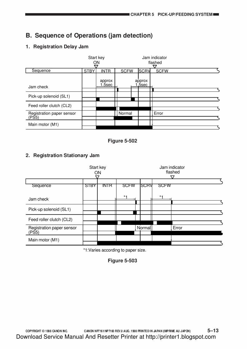
7/16/2019 Canon Np7161-Np7160 Copier Sm
http://slidepdf.com/reader/full/canon-np7161-np7160-copier-sm 133/345
COPYRIGHT © 1998 CANON INC. CANON NP7161/NP7160 REV.0 AUG. 1998 PRINTED IN JAPAN (IMPRIME AU JAPON) 5–13
CHAPTER 5 PICK-UP/FEEDING SYSTEM
B. Sequence of Operations (jam detection)
1. Registration Delay Jam
Figure 5-502
2. Registration Stationary Jam
Start keyON
Jam indicatorflashed
STBY SCFWSCRVSCFWINTRSequence
Pick-up solenoid (SL1)
Registration paper sensor(PS5)
Feed roller clutch (CL2)
Main motor (M1)
Jam check
approx1.5sec
Normal Error
approx1.5sec
Start key
ON
Jam indicatorflashed
STBY SCFWSCRVSCFWINTRSequence
Pick-up solenoid (SL1)
Registration paper sensor(PS5)
Feed roller clutch (CL2)
Main motor (M1)
Jam check *1
Normal
*1
Error
*1:Varies according to paper size.
Figure 5-503
Download Service Manual And Resetter Printer at http://printer1.blogspot.com

7/16/2019 Canon Np7161-Np7160 Copier Sm
http://slidepdf.com/reader/full/canon-np7161-np7160-copier-sm 134/345
CHAPTER 5 PICK-UP/FEEDING SYSTEM
5–14 COPYRIGHT © 1998 CANON INC. CANON NP7161/NP7160 REV.0 AUG. 1998 PRINTED IN JAPAN (IMPRIME AU JAPON)
3. Delivery Delay Jam
Start keyON
STBY SCRVSCFWSCRVSCFWINTRSequence
Registration roller clutch(CL1)
Main motor (M1)
Jam check
Delivery paper sensor (PS6)
Jam indicatorflashed
Normal Error
approx 2.2secapprox 2.2sec
Figure 5-504
4. Delivery Stationary Jam
Figure 5-505
Start keyON
Jam indicatorflashed
STBY LSTRSCRVSCFWSCRVSCFWINTRSequence
Registration roller clutch(CL1)
Main motor (M1)
Jam check
Delivery paper sensor (PS6) Normal
*1
Error
*1
*1:Varies according to paper size.
Download Service Manual And Resetter Printer at http://printer1.blogspot.com

7/16/2019 Canon Np7161-Np7160 Copier Sm
http://slidepdf.com/reader/full/canon-np7161-np7160-copier-sm 135/345
COPYRIGHT © 1998 CANON INC. CANON NP7161/NP7160 REV.0 AUG. 1998 PRINTED IN JAPAN (IMPRIME AU JAPON) 5–15
CHAPTER 5 PICK-UP/FEEDING SYSTEM
VI. DISASSEMBLY/ASSEMBLY
The copier may be disassembled and assembled as shown here. Pay attention to the copier’s
mechanical characteristics along with the steps for disassembly/assembly.
Important:
1. Turn off the power and disconnect the power plug to ensure safety whenever disassembling/
assembling the copier.
2. Unless otherwise noted, assemble the parts by reversing the steps used to disassemble them.
3. Identify the screws by type (length, diameter) to avoid use in the wrong location.
4. Use a washer where needed. The mounting screws used for the grounding wire and varistor
come with a washer to ensure electric continuity. Do not forget to use these washers.
5. As a rule, do not operate the copier with any of its parts removed.
Download Service Manual And Resetter Printer at http://printer1.blogspot.com
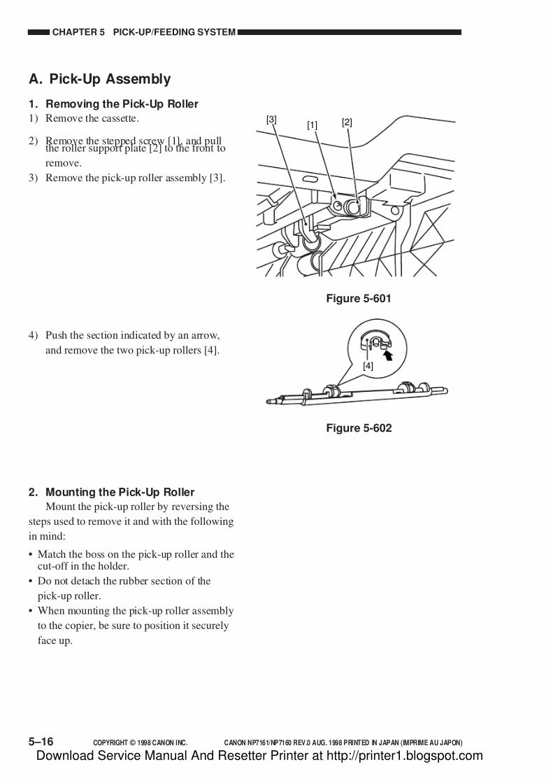
7/16/2019 Canon Np7161-Np7160 Copier Sm
http://slidepdf.com/reader/full/canon-np7161-np7160-copier-sm 136/345
CHAPTER 5 PICK-UP/FEEDING SYSTEM
5–16 COPYRIGHT © 1998 CANON INC. CANON NP7161/NP7160 REV.0 AUG. 1998 PRINTED IN JAPAN (IMPRIME AU JAPON)
[2][1][3]
Figure 5-601
[4]
Figure 5-602
A. Pick-Up Assembly
1. Removing the Pick-Up Roller
1) Remove the cassette.
2) Remove the stepped screw [1], and pullthe roller support plate [2] to the front to
remove.
3) Remove the pick-up roller assembly [3].
4) Push the section indicated by an arrow,
and remove the two pick-up rollers [4].
2. Mounting the Pick-Up Roller
Mount the pick-up roller by reversing the
steps used to remove it and with the following
in mind:
• Match the boss on the pick-up roller and thecut-off in the holder.
• Do not detach the rubber section of the
pick-up roller.
• When mounting the pick-up roller assembly
to the copier, be sure to position it securely
face up.
Download Service Manual And Resetter Printer at http://printer1.blogspot.com
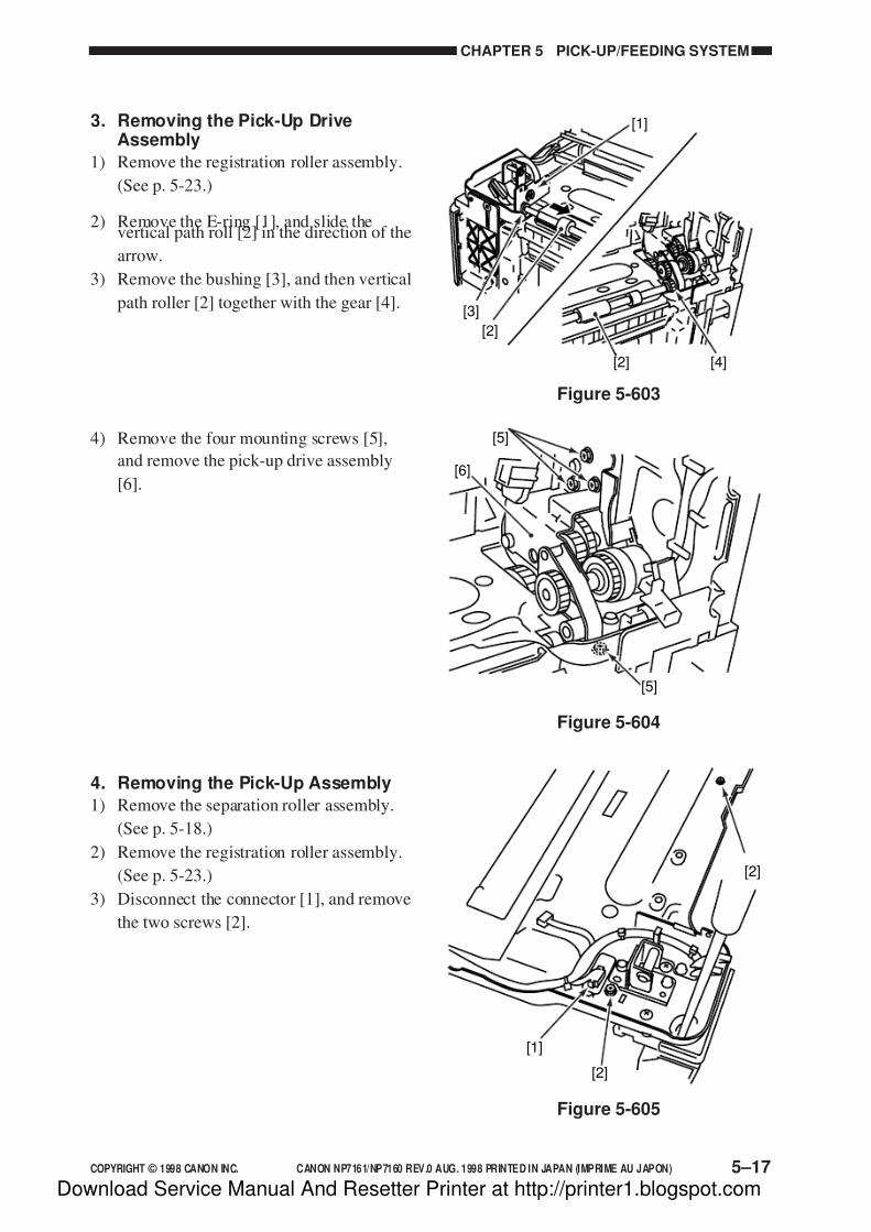
7/16/2019 Canon Np7161-Np7160 Copier Sm
http://slidepdf.com/reader/full/canon-np7161-np7160-copier-sm 137/345
COPYRIGHT © 1998 CANON INC. CANON NP7161/NP7160 REV.0 AUG. 1998 PRINTED IN JAPAN (IMPRIME AU JAPON) 5–17
CHAPTER 5 PICK-UP/FEEDING SYSTEM
[1]
[3]
[2]
[4][2]
Figure 5-603
[5]
[5]
[6]
Figure 5-604
[1]
[2]
[2]
Figure 5-605
3. Removing the Pick-Up DriveAssembly
1) Remove the registration roller assembly.
(See p. 5-23.)
2) Remove the E-ring [1], and slide thevertical path roll [2] in the direction of the
arrow.
3) Remove the bushing [3], and then vertical
path roller [2] together with the gear [4].
4) Remove the four mounting screws [5],
and remove the pick-up drive assembly
[6].
4. Removing the Pick-Up Assembly
1) Remove the separation roller assembly.
(See p. 5-18.)
2) Remove the registration roller assembly.
(See p. 5-23.)
3) Disconnect the connector [1], and remove
the two screws [2].
Download Service Manual And Resetter Printer at http://printer1.blogspot.com
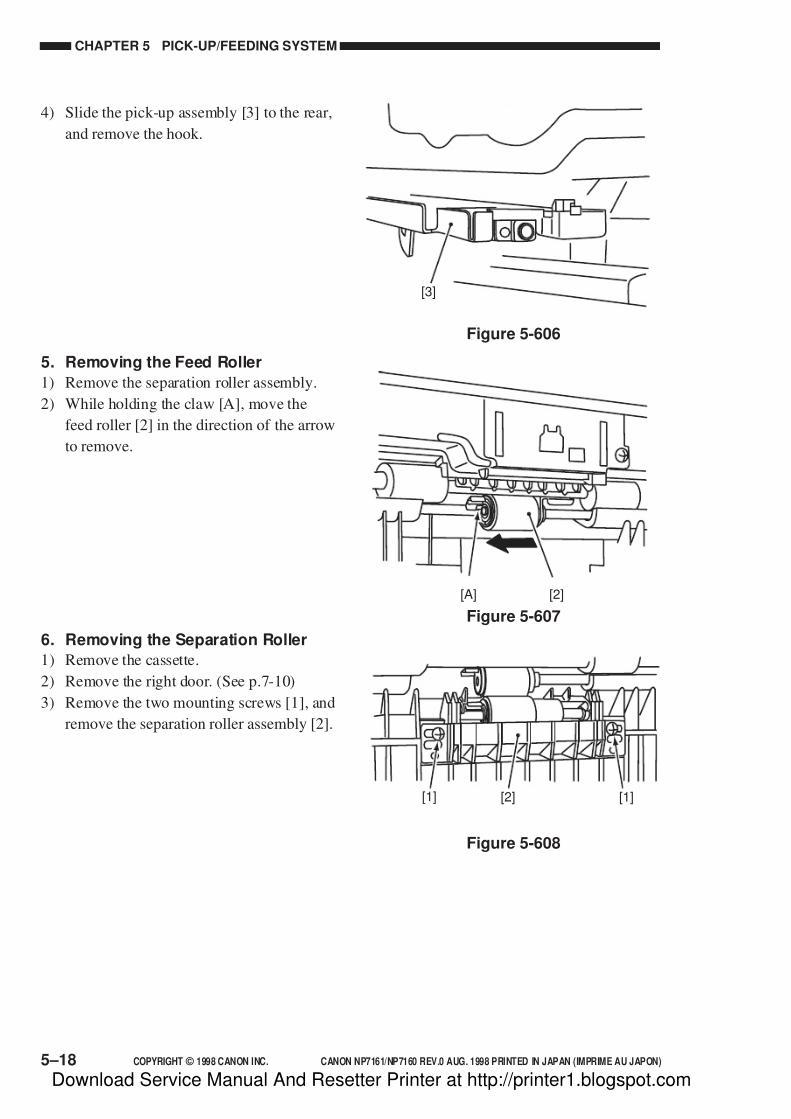
7/16/2019 Canon Np7161-Np7160 Copier Sm
http://slidepdf.com/reader/full/canon-np7161-np7160-copier-sm 138/345
CHAPTER 5 PICK-UP/FEEDING SYSTEM
5–18 COPYRIGHT © 1998 CANON INC. CANON NP7161/NP7160 REV.0 AUG. 1998 PRINTED IN JAPAN (IMPRIME AU JAPON)
4) Slide the pick-up assembly [3] to the rear,
and remove the hook.
5. Removing the Feed Roller
1) Remove the separation roller assembly.
2) While holding the claw [A], move the
feed roller [2] in the direction of the arrow
to remove.
6. Removing the Separation Roller
1) Remove the cassette.
2) Remove the right door. (See p.7-10)
3) Remove the two mounting screws [1], and
remove the separation roller assembly [2].
[3]
Figure 5-606
[2][A]
Figure 5-607
[2] [1][1]
Figure 5-608
Download Service Manual And Resetter Printer at http://printer1.blogspot.com

7/16/2019 Canon Np7161-Np7160 Copier Sm
http://slidepdf.com/reader/full/canon-np7161-np7160-copier-sm 139/345
COPYRIGHT © 1998 CANON INC. CANON NP7161/NP7160 REV.0 AUG. 1998 PRINTED IN JAPAN (IMPRIME AU JAPON) 5–19
CHAPTER 5 PICK-UP/FEEDING SYSTEM
[3]
Figure 5-612
[5]
[4]
Figure 5-609
Figure 5-610
[1][2]
4) Remove the roller cover [3].
5) Remove the two bushings [4], and remove
the two springs [5].
6) While pushing the claw [A] with a flat-
blade screwdriver, remove the separation
roller [6].
7. Mounting the Separation Roller
Mount the separation roller by reversing
the steps used to remove it and with the
following in mind:
• When mounting the separation roller, be
sure to fit the pin [1] in the groove [2]
of the holder.
• When mounting the roller cover, be sure
so that the roller cover will push against
the bushing.
Figure 5-611
[A]
[6]
Download Service Manual And Resetter Printer at http://printer1.blogspot.com

7/16/2019 Canon Np7161-Np7160 Copier Sm
http://slidepdf.com/reader/full/canon-np7161-np7160-copier-sm 140/345
CHAPTER 5 PICK-UP/FEEDING SYSTEM
5–20 COPYRIGHT © 1998 CANON INC. CANON NP7161/NP7160 REV.0 AUG. 1998 PRINTED IN JAPAN (IMPRIME AU JAPON)
Figure 5-613
Figure 5-614
[1]
[2]
Figure 5-615
[1]
[3]
[2]
B. Multifeeder Assembly
1. Removing the Multifeeder Tray
1) Open the multifeeder tray, and remove the
face cover [1] using a flat-bladescrewdriver.
2) Remove the guide pin [2], and remove themultifeeder tray [3].
2. Removing the MultifeederAssembly
1) Remove the rear cover, and open the right
door.
2) Remove the lower inside cover. (See p.7-
12.)
3) Disconnect the two connectors [1], and
remove the mounting screw [2].
Download Service Manual And Resetter Printer at http://printer1.blogspot.com

7/16/2019 Canon Np7161-Np7160 Copier Sm
http://slidepdf.com/reader/full/canon-np7161-np7160-copier-sm 141/345
COPYRIGHT © 1998 CANON INC. CANON NP7161/NP7160 REV.0 AUG. 1998 PRINTED IN JAPAN (IMPRIME AU JAPON) 5–21
CHAPTER 5 PICK-UP/FEEDING SYSTEM
Figure 5-616
[3]
[2]
[1]
Figure 5-617
[1]
Figure 5-618
[4] [4][5]
[3]
The two holes each(upper/lower) arespare holes.
4) Disconnect the two connectors [3], and
remove the three mounting screws [4];
then, detach the multifeeder assembly [5].
3. Removing the Multifeeder Pick-UpRoller
1) Remove the developing assembly. (See p.
4-37.)
2) Remove the drum unit. (See p. 4-28.)
3) Remove the E-ring [1]; then, while
pushing down the multifeeder separation
pad [2] to free it from pressure, detach the
multifeeder pick-up roller [3].
4. Removing the Separation Pad
1) Execute service mode 402 (multifeederholding plate release) in standby state so
as to lift the multifeeder holding plate [1].
Download Service Manual And Resetter Printer at http://printer1.blogspot.com

7/16/2019 Canon Np7161-Np7160 Copier Sm
http://slidepdf.com/reader/full/canon-np7161-np7160-copier-sm 142/345
CHAPTER 5 PICK-UP/FEEDING SYSTEM
5–22 COPYRIGHT © 1998 CANON INC. CANON NP7161/NP7160 REV.0 AUG. 1998 PRINTED IN JAPAN (IMPRIME AU JAPON)
Figure 5-621
[2]
[B]
[A]
[1]
[5] [4]
[2]
[3]
Figure 5-620
Figure 5-619
5) Detach the multifeeder separation pad [5]
from the holder [4].
5. Adjusting the Pressure of theSeparation Pad
If double feeding or pick-up failure
occurs, loosen the adjusting screw [1] and
relocate the holder [2] to adjust the force of
the separation pad tension spring.
• If pick-up failure occurs, move the holder in
the direction of [A].
• If double feeding occurs, move the holder
in the direction of [B].
2) Turn off the copier, and disconnect the
power plug.
Caution:
Whenever you need to performdisassembly/assembly work, be sure
to turn off the copier and disconnect
its power plug.
3) Open the right door.
4) Remove the mounting screw [2], and slide
the multifeeder separation pad assembly
[3] in the direction of the arrow to
remove.
Download Service Manual And Resetter Printer at http://printer1.blogspot.com
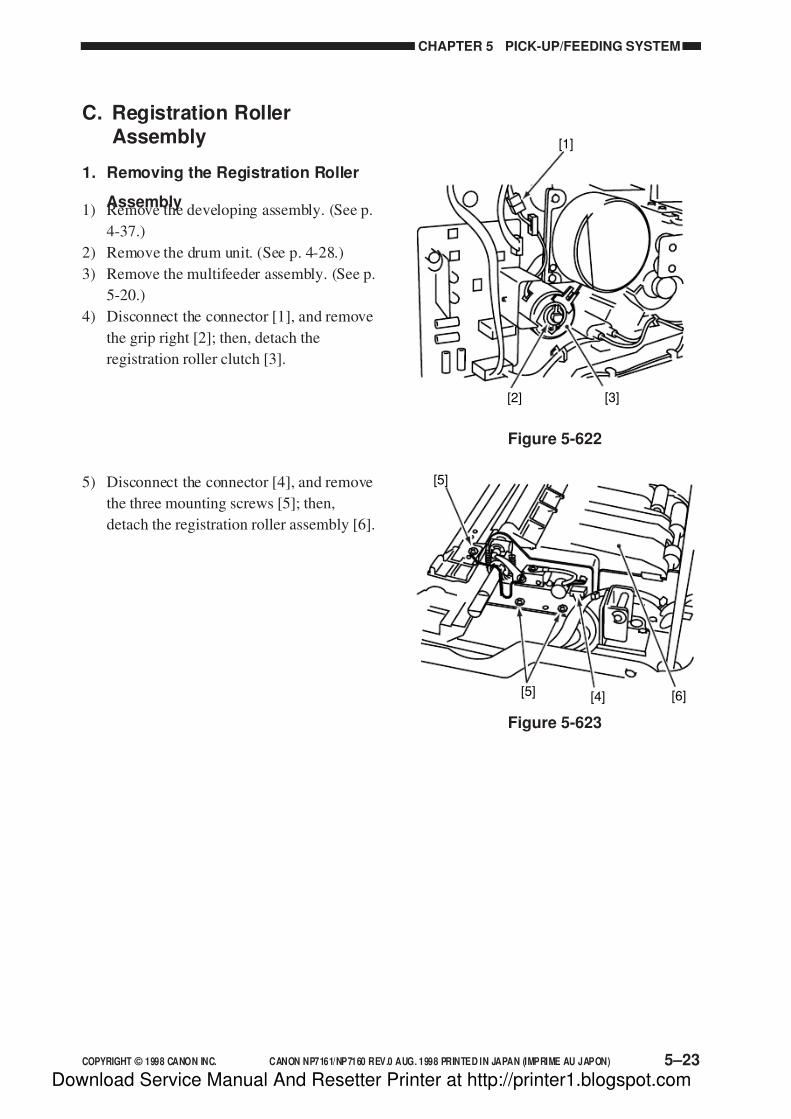
7/16/2019 Canon Np7161-Np7160 Copier Sm
http://slidepdf.com/reader/full/canon-np7161-np7160-copier-sm 143/345
COPYRIGHT © 1998 CANON INC. CANON NP7161/NP7160 REV.0 AUG. 1998 PRINTED IN JAPAN (IMPRIME AU JAPON) 5–23
CHAPTER 5 PICK-UP/FEEDING SYSTEM
[3][2]
[1]
Figure 5-622
[5]
[5] [4] [6]
Figure 5-623
C. Registration RollerAssembly
1. Removing the Registration Roller
Assembly1) Remove the developing assembly. (See p.
4-37.)
2) Remove the drum unit. (See p. 4-28.)
3) Remove the multifeeder assembly. (See p.
5-20.)
4) Disconnect the connector [1], and remove
the grip right [2]; then, detach the
registration roller clutch [3].
5) Disconnect the connector [4], and remove
the three mounting screws [5]; then,
detach the registration roller assembly [6].
Download Service Manual And Resetter Printer at http://printer1.blogspot.com

7/16/2019 Canon Np7161-Np7160 Copier Sm
http://slidepdf.com/reader/full/canon-np7161-np7160-copier-sm 144/345
CHAPTER 5 PICK-UP/FEEDING SYSTEM
5–24 COPYRIGHT © 1998 CANON INC. CANON NP7161/NP7160 REV.0 AUG. 1998 PRINTED IN JAPAN (IMPRIME AU JAPON)
D. Cassette Assembly
1. Removing the Cassette Size Switch
1) Remove the cassette.
2) Remove the delivery lower cover. (Seep.7-11)
3) Disconnect the connector [1] (J110) of the
DC controller PCB, and remove the
mounting screw [2] ; then, free the
harness from the harness guide.
4) Remove the mounting screw [3], and
remove the stopper [4].
5) Remove the cassette switch assembly [5].
6) Remove the hook [6], and remove the
cassette size switch [7].
Caution:
When mounting the cassette size
switch assembly, check to make sure
that the cassette size switch assembly
slides normally by the work of the
spring [8] pressure.
[3] [4] [5]
[2][1]
Figure 5-624
Figure 5-625
Figure 5-626
[7] [6][8]
Download Service Manual And Resetter Printer at http://printer1.blogspot.com

7/16/2019 Canon Np7161-Np7160 Copier Sm
http://slidepdf.com/reader/full/canon-np7161-np7160-copier-sm 145/345
COPYRIGHT © 1998 CANON INC. CANON NP7161/NP7160 REV.0 AUG. 1998 PRINTED IN JAPAN (IMPRIME AU JAPON) 5–25
CHAPTER 5 PICK-UP/FEEDING SYSTEM
•AB
•INCH
[1][2]
[1][2]
Figure 5-627
[3]
[4]
[3]
[4]
•AB
•INCH
2. Changing the Cassette Size (AB/INCH)
1) Slide out the cassette.
2) Loosen the mounting screw [1] on the left
side of the cassette; then, slide the sizeswitching block [2] to the desired size
position, and fix it in place.
3) Remove the mounting screw [3]; then,
slide the size switching lever [4] to the
desired size position, and fix it in place.
Figure 5-628
Download Service Manual And Resetter Printer at http://printer1.blogspot.com
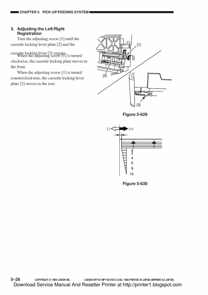
7/16/2019 Canon Np7161-Np7160 Copier Sm
http://slidepdf.com/reader/full/canon-np7161-np7160-copier-sm 146/345
CHAPTER 5 PICK-UP/FEEDING SYSTEM
5–26 COPYRIGHT © 1998 CANON INC. CANON NP7161/NP7160 REV.0 AUG. 1998 PRINTED IN JAPAN (IMPRIME AU JAPON)
3. Adjusting the Left/RightRegistration
Turn the adjusting screw [1] until the
cassette locking lever plate [2] and the
cassette locking lever [3] engage.When the adjusting screw [1] is turned
clockwise, the cassette locking plate moves to
the front.
When the adjusting screw [1] is turned
counterclockwise, the cassette locking lever
plate [2] moves to the rear.
[3]
[1]
[2]
Figure 5-629
Figure 5-630
02
4
6
8
10
(-) (+)
Download Service Manual And Resetter Printer at http://printer1.blogspot.com

7/16/2019 Canon Np7161-Np7160 Copier Sm
http://slidepdf.com/reader/full/canon-np7161-np7160-copier-sm 147/345
COPYRIGHT © 1998 CANON INC. CANON NP7161/NP7160 REV.0 AUG. 1998 PRINTED IN JAPAN (IMPRIME AU JAPON)
CHAPTER 6
FIXING SYSTEM
I. OUTLINE OF OPERATION ..................... 6-1
A. Outline ................................................ 6-1B. Controlling the Fixing Temperature ... 6-2C. Error Detection Circuit ........................ 6-5
II. DISASSEMBLY/ASSEMBLY ................... 6-7
A. Fixing Assembly ................................. 6-8B. Delivery Assembly............................ 6-16
This chapter explains the principles used to fuse toner images to transfer medium in view of the func-
tions of electrical and mechanical units and in relation to their timing of operation. It also shows how
these units may be disassembled/assembled and adjusted.
Download Service Manual And Resetter Printer at http://printer1.blogspot.com

7/16/2019 Canon Np7161-Np7160 Copier Sm
http://slidepdf.com/reader/full/canon-np7161-np7160-copier-sm 148/345
Download Service Manual And Resetter Printer at http://printer1.blogspot.com
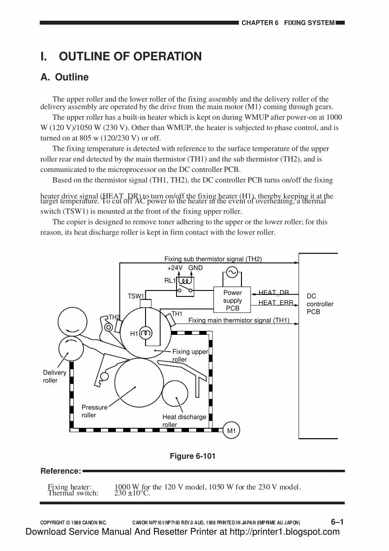
7/16/2019 Canon Np7161-Np7160 Copier Sm
http://slidepdf.com/reader/full/canon-np7161-np7160-copier-sm 149/345
COPYRIGHT © 1998 CANON INC. CANON NP7161/NP7160 REV.0 AUG. 1998 PRINTED IN JAPAN (IMPRIME AU JAPON) 6–1
CHAPTER 6 FIXING SYSTEM
Figure 6-101
I. OUTLINE OF OPERATION
A. Outline
The upper roller and the lower roller of the fixing assembly and the delivery roller of thedelivery assembly are operated by the drive from the main motor (M1) coming through gears.
The upper roller has a built-in heater which is kept on during WMUP after power-on at 1000
W (120 V)/1050 W (230 V). Other than WMUP, the heater is subjected to phase control, and is
turned on at 805 w (120/230 V) or off.
The fixing temperature is detected with reference to the surface temperature of the upper
roller rear end detected by the main thermistor (TH1) and the sub thermistor (TH2), and is
communicated to the microprocessor on the DC controller PCB.
Based on the thermistor signal (TH1, TH2), the DC controller PCB turns on/off the fixing
heater drive signal (HEAT_DR) to turn on/off the fixing heater (H1), thereby keeping it at thetarget temperature. To cut off AC power to the heater in the event of overheating, a thermal
switch (TSW1) is mounted at the front of the fixing upper roller.
The copier is designed to remove toner adhering to the upper or the lower roller; for this
reason, its heat discharge roller is kept in firm contact with the lower roller.
Reference:
Fixing heater: 1000 W for the 120 V model, 1050 W for the 230 V model.Thermal switch: 230 ±10°C.
Fixing sub thermistor signal (TH2)
Fixing main thermistor signal (TH1)
HEAT _ DR
HEAT _ ERRTSW1
RL1
+24V GND
PowersupplyPCB
H1
TH2TH1
DCcontrollerPCB
Heat dischargeroller
Fixing upperroller
Pressureroller
Deliveryroller
M1
Download Service Manual And Resetter Printer at http://printer1.blogspot.com

7/16/2019 Canon Np7161-Np7160 Copier Sm
http://slidepdf.com/reader/full/canon-np7161-np7160-copier-sm 150/345
CHAPTER 6 FIXING SYSTEM
6–2 COPYRIGHT © 1998 CANON INC. CANON NP7161/NP7160 REV.0 AUG. 1998 PRINTED IN JAPAN (IMPRIME AU JAPON)
B. Controlling the Fixing Temperature
The copier uses two thermistors mounted at the rear ends of the upper roller to monitor
surface temperature. When copies are made continuously using sheets of B4 or less, the
temperature of the area (center) coming into contact with the paper will be lower than thetemperature of the areas (ends) not coming into contact with the paper. To prevent such a
problem, the target temperature is varied in steps to suit the width of copy paper and the
temperature detected by the thermistor during copying operation.
To improve fixing on rough surface paper or tracing paper, a special paper mode (U13) has
been added to user mode, thereby enabling a target temperature unique to these types of paper.
• Paper Width >257 mm
Table 6-101
• 257 mm > Paper Width > 216 mm
Table 6-102
• 216 mm > Paper Width > 182 mm
Table 6-103
Temperature detected by
thermistor at Start key on
Target temperature immediatelyafter Start key on
Target temperature duringcontinuous copying (upper limit)
Less than 170°C
170°C or more, less than 180°C
180°C or more, less than 190°C
190°C or more
179°C
188°C
193°C
193°C
196°C
201°C
206°C
211°C
169°C
178°C
183°C
183°C
193°C 211°C 183°C
General plain paper Paper with rough surface Tracing paper General plain paper Paper with rough surface Tracing paper
Temperature detected by
thermistor at Start key on
Target temperature immediatelyafter Start key on
Target temperature duringcontinuous copying (upper limit)
Less than 170°C
170°C or more, less than 180°C
180°C or more, less than 190°C
190°C or more
171°C
181°C
181°C
181°C
196°C
200°C
206°C
209°C
161°C
171°C
171°C
171°C
181°C 209°C 171°C
General plain paper Paper with rough surface Tracing paper General plain paper Paper with rough surface Tracing paper
Temperature detected by
thermistor at Start key on
Target temperature immediatelyafter Start key on
Target temperature duringcontinuous copying (upper limit)
Less than 170°C
170°C or more, less than 180°C
180°C or more, less than 190°C
190°C or more
177°C
186°C
192°C
200°C
196°C
202°C
207°C
214°C
167°C
176°C
182°C
190°C
200°C 214°C 190°C
General plain paper Paper with rough surface Tracing paper General plain paper Paper with rough surface Tracing paper
Download Service Manual And Resetter Printer at http://printer1.blogspot.com

7/16/2019 Canon Np7161-Np7160 Copier Sm
http://slidepdf.com/reader/full/canon-np7161-np7160-copier-sm 151/345
COPYRIGHT © 1998 CANON INC. CANON NP7161/NP7160 REV.0 AUG. 1998 PRINTED IN JAPAN (IMPRIME AU JAPON) 6–3
CHAPTER 6 FIXING SYSTEM
• 182 mm > Paper Width
Table 6-104
Temperature detected by
thermistor at Start key on
Target temperature immediatelyafter Start key on
Target temperature duringcontinuous copying (upper limit)
Less than 170°C
170°C or more, less than 180°C
180°C or more, less than 190°C
190°C or more
175°C
186°C
194°C
200°C
196°C
204°C
208°C
215°C
165°C
176°C
184°C
190°C
200°C 215°C 190°C
General plain paper Paper with rough surface Tracing paper General plain paper Paper with rough surface Tracing paper
• From Power-On to End of Copying
Figure 6-102
120°C
140°C
160°C
180°C
200°C
220°C
*1
,
Start keyON
Power switchON
WMUP WMUPR STBY INTR COPY LSTR STBYSequence
Main motor (M1)
Fixing heater (H1)
Wait indicator Green(flashing) Orange
*1:Varies according to paper width.
General plain paper mode
Tracing paper mode
Paper with rough surface mode
Target temperature control
Download Service Manual And Resetter Printer at http://printer1.blogspot.com
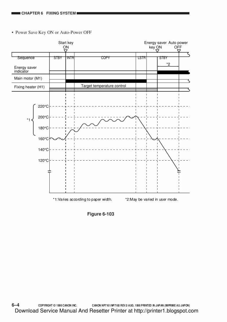
7/16/2019 Canon Np7161-Np7160 Copier Sm
http://slidepdf.com/reader/full/canon-np7161-np7160-copier-sm 152/345
CHAPTER 6 FIXING SYSTEM
6–4 COPYRIGHT © 1998 CANON INC. CANON NP7161/NP7160 REV.0 AUG. 1998 PRINTED IN JAPAN (IMPRIME AU JAPON)
• Power Save Key ON or Auto-Power OFF
Figure 6-103
120°C
140°C
160°C
180°C
200°C
220°C
*1
Start keyON
STBY INTR COPY LSTR STBYSequence
Main motor (M1)
Fixing heater (H1)
Energy saverindicator
*1:Varies according to paper width. *2:May be varied in user mode.
Energy saverkey ON
Auto powerOFF
*2
Target temperature control
Download Service Manual And Resetter Printer at http://printer1.blogspot.com

7/16/2019 Canon Np7161-Np7160 Copier Sm
http://slidepdf.com/reader/full/canon-np7161-np7160-copier-sm 153/345
COPYRIGHT © 1998 CANON INC. CANON NP7161/NP7160 REV.0 AUG. 1998 PRINTED IN JAPAN (IMPRIME AU JAPON) 6–5
CHAPTER 6 FIXING SYSTEM
C. Error Detection Circuit
1. Outline
The copier’s error detection circuit is constructed as shown in Figure 6-104, and monitors the
following items for an error:• Surface temperature of the upper fixing roller
• Activation of the fixing heater (H1)
Figure 6-104
DC controller PCB
Power supply PCBHVT
Fixing assembly
TH2
T H 2
TH1
T H 1
H E A T_
E R R
A C_
2 4 V_ O
N
T H 1_
D T
J 1 0 8 - 3 - 2 - 4 - 1
J 1 0 9 - 2 - 1
J 1 0 6
- 1 9
J 1 0 6
- 2 4
J 2 1 2 - 6
J 2 1 2 - 1
TSWH1
+5V
+5V
+5V +5V
Buffer
Buffer
+-
-+
Gatearraytimer
Errordetection
circuit
IC119
CPU
IC113Heater ONdetection
Converter
ACdriver
RL1J201
-2
-1
J210-1-2
LF
DS1 RL
CB1
CB2
AC power line
DC signal line
+24V
Download Service Manual And Resetter Printer at http://printer1.blogspot.com

7/16/2019 Canon Np7161-Np7160 Copier Sm
http://slidepdf.com/reader/full/canon-np7161-np7160-copier-sm 154/345
CHAPTER 6 FIXING SYSTEM
6–6 COPYRIGHT © 1998 CANON INC. CANON NP7161/NP7160 REV.0 AUG. 1998 PRINTED IN JAPAN (IMPRIME AU JAPON)
2. Surface Temperature of the Fixing Upper Roller
The main thermistor (TH1) and the sub thermistor are arranged nearby at the rear of the
fixing upper roller, and are used to monitor the difference in voltage between two thermistor
signals (TH1, TH2).
If either thermistor suffers an open circuit, the CW input terminal of the differential amplifiercircuit will be about 5 V. At this time, the voltage of the other thermistor will decrease as the
surface temperature of the fixing upper roller increases, gradually increasing the output of the
differential amplifier circuit.
When the output of the differential amplifier circuit exceeds the value set on the comparator,
the comparator will send a signal to the gate array. When the gate array detects the signal from
the comparator for a specific period of time, the DC controller PCB will cut off 24 V and AC
power supply and, at the same time, will indicate ‘E000’, ‘E002’, or ‘E003’.
If the connector of the main thermistor is not connected or both thermistors suffer an open
circuit, the microprocessor will not be able to detect any excess increases in the surfacetemperature of the fixing upper roller, causing it to indicate ‘E000’, ‘E002’, or ‘E003’ on the
control panel.
3. Activation of the Fixing Heater (H1)
The fixing heater error signal (HEAT_ERR) from the AC drier is monitored by IC113 on the
DC controller PCB, and its reading is compared against the fixing heater drive signal
(HEAT_DR) to find out whether the power to the fixing heater is normal or not.
If the microprocessor on the DC controller PCB identifies the state of the fixing heater to be
faulty, it will cut the power supplied to the fixing heater and, at the same time, will indicate
‘E001’ on the control panel.
Download Service Manual And Resetter Printer at http://printer1.blogspot.com

7/16/2019 Canon Np7161-Np7160 Copier Sm
http://slidepdf.com/reader/full/canon-np7161-np7160-copier-sm 155/345
COPYRIGHT © 1998 CANON INC. CANON NP7161/NP7160 REV.0 AUG. 1998 PRINTED IN JAPAN (IMPRIME AU JAPON) 6–7
CHAPTER 6 FIXING SYSTEM
II. DISASSEMBLY/ASSEMBLY
The copier may be disassembled and assembled as shown here. Pay attention to the copier’s
mechanical characteristics along with the steps for disassembly/assembly.
Important:
1. Turn off the power and disconnect the power plug to ensure safety whenever
disassembling/assembling the copier.
2. Unless otherwise noted, assemble the parts by reversing the steps used to disassemble
them.
3. Identify the screws by type (length, diameter) to avoid use in the wrong location.
4. Use a washer where needed. The mounting screws used for the grounding wire and
varistor come with a washer to ensure electric continuity. Do not forget to use these
washers.5. As a rule, do not operate the copier with any of its parts removed.
Download Service Manual And Resetter Printer at http://printer1.blogspot.com
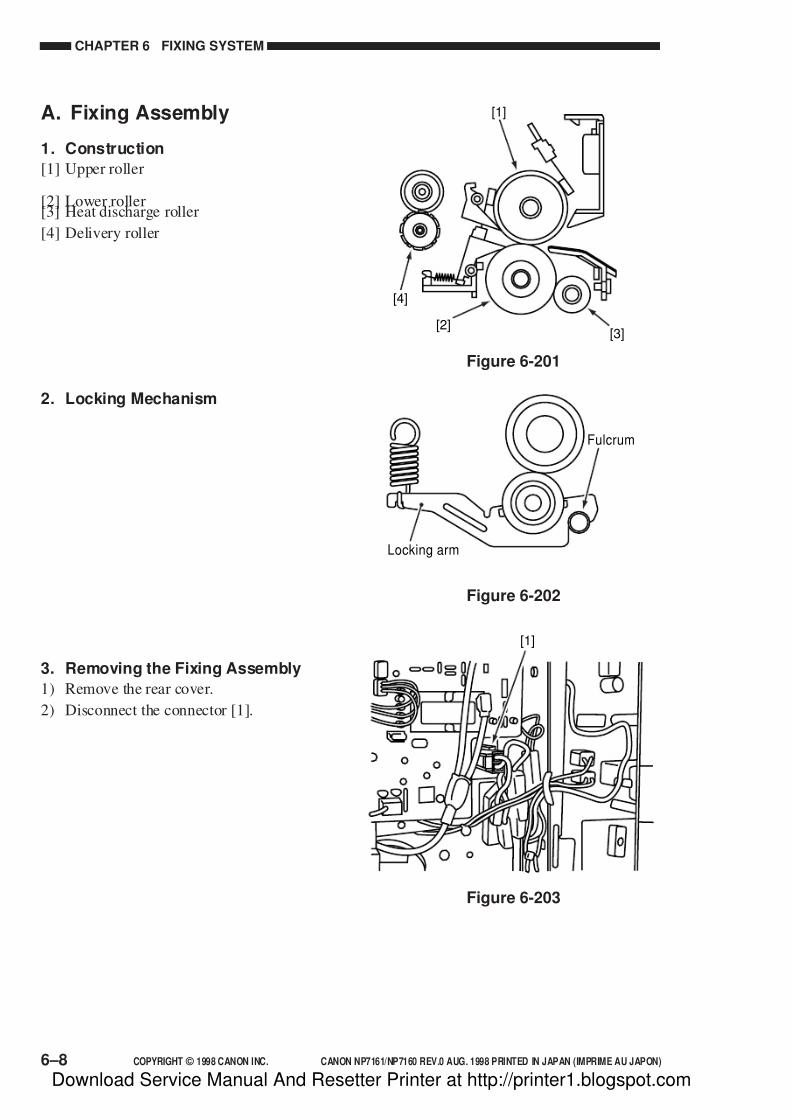
7/16/2019 Canon Np7161-Np7160 Copier Sm
http://slidepdf.com/reader/full/canon-np7161-np7160-copier-sm 156/345
CHAPTER 6 FIXING SYSTEM
6–8 COPYRIGHT © 1998 CANON INC. CANON NP7161/NP7160 REV.0 AUG. 1998 PRINTED IN JAPAN (IMPRIME AU JAPON)
Figure 6-203
[1]
[4]
[3][2]
Fulcrum
Locking arm
Figure 6-201
Figure 6-202
[1]
A. Fixing Assembly
1. Construction
[1] Upper roller
[2] Lower roller[3] Heat discharge roller
[4] Delivery roller
2. Locking Mechanism
3. Removing the Fixing Assembly
1) Remove the rear cover.
2) Disconnect the connector [1].
Download Service Manual And Resetter Printer at http://printer1.blogspot.com
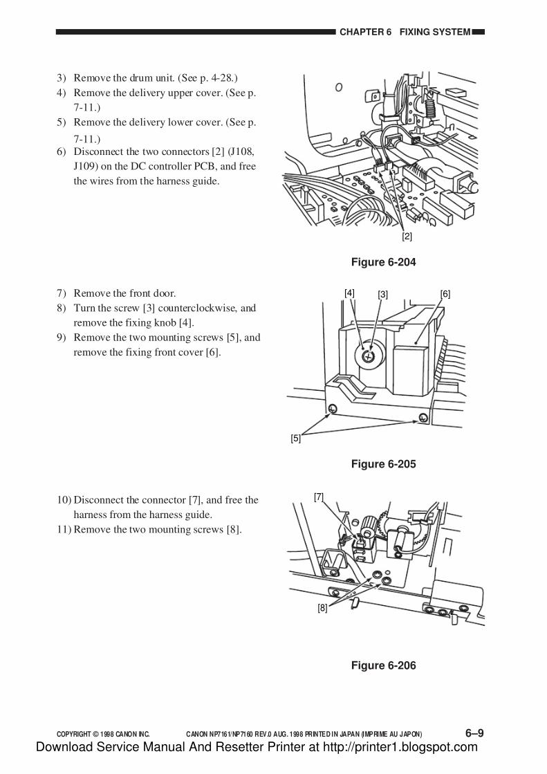
7/16/2019 Canon Np7161-Np7160 Copier Sm
http://slidepdf.com/reader/full/canon-np7161-np7160-copier-sm 157/345
COPYRIGHT © 1998 CANON INC. CANON NP7161/NP7160 REV.0 AUG. 1998 PRINTED IN JAPAN (IMPRIME AU JAPON) 6–9
CHAPTER 6 FIXING SYSTEM
Figure 6-204
Figure 6-205
Figure 6-206
[8]
[7]
[5]
[3][4] [6]
[2]
3) Remove the drum unit. (See p. 4-28.)
4) Remove the delivery upper cover. (See p.
7-11.)
5) Remove the delivery lower cover. (See p.
7-11.)6) Disconnect the two connectors [2] (J108,
J109) on the DC controller PCB, and free
the wires from the harness guide.
7) Remove the front door.
8) Turn the screw [3] counterclockwise, and
remove the fixing knob [4].
9) Remove the two mounting screws [5], and
remove the fixing front cover [6].
10) Disconnect the connector [7], and free the
harness from the harness guide.
11) Remove the two mounting screws [8].
Download Service Manual And Resetter Printer at http://printer1.blogspot.com

7/16/2019 Canon Np7161-Np7160 Copier Sm
http://slidepdf.com/reader/full/canon-np7161-np7160-copier-sm 158/345
CHAPTER 6 FIXING SYSTEM
6–10 COPYRIGHT © 1998 CANON INC. CANON NP7161/NP7160 REV.0 AUG. 1998 PRINTED IN JAPAN (IMPRIME AU JAPON)
[9]
Figure 6-207
12) Lift the front of the fixing assembly [9]
slightly to remove.
Caution:
When removing the fixing assembly,take care not to damage the feeding
assembly.
Figure 6-208
[2]
[3]
[1]
4. Removing the Fixing Heater1) Remove the fixing assembly. (See p. 6-8.)
2) Disconnect the two connectors [1], and
free the harness from the harness guide.
3) Remove the mounting screw [2], and
detach the heater support plate (front) [3].
[5][6]
[7]
[8]
[4]
Figure 6-209
4) Remove the mounting screw [4], and free
the harness from the harness guide; then,
detach the connector support plate [5].
5) Disconnect all connectors [6] from the
connector support plate [5].
6) Remove the mounting screw [7], and free
the harness; then, detach the harness guide
[8].
Download Service Manual And Resetter Printer at http://printer1.blogspot.com

7/16/2019 Canon Np7161-Np7160 Copier Sm
http://slidepdf.com/reader/full/canon-np7161-np7160-copier-sm 159/345
COPYRIGHT © 1998 CANON INC. CANON NP7161/NP7160 REV.0 AUG. 1998 PRINTED IN JAPAN (IMPRIME AU JAPON) 6–11
CHAPTER 6 FIXING SYSTEM
Figure 6-210
Figure 6-211
[13][12]
[10]
[9]
[10][11]
7) Free the harness from the harness retainer
[9].
8) Remove the two mounting screws [10],
and detach the heater support plate (rear)
[11].
9) Free the harness from the harness guide[12], and detach the fixing heater [13].
Caution:
1.Do not start work if the surface of
the fixing heater is hot.
2.Do not touch the surface of the
fixing heater.
3.If the surface of the fixing heater is
soiled, dry wipe it.
Figure 6-212
[1]5. Removing the Thermal Switch
Assembly
1) Remove the fixing assembly. (See p. 6-8.)
2) Disconnect the two connectors [1].
Download Service Manual And Resetter Printer at http://printer1.blogspot.com
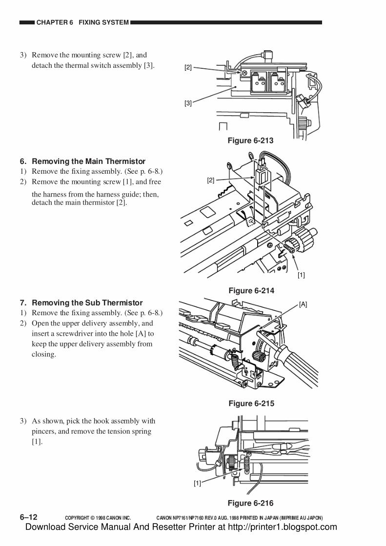
7/16/2019 Canon Np7161-Np7160 Copier Sm
http://slidepdf.com/reader/full/canon-np7161-np7160-copier-sm 160/345
CHAPTER 6 FIXING SYSTEM
6–12 COPYRIGHT © 1998 CANON INC. CANON NP7161/NP7160 REV.0 AUG. 1998 PRINTED IN JAPAN (IMPRIME AU JAPON)
[2]
[3]
Figure 6-213
[1]
Figure 6-216
[2]
[1]
Figure 6-214
[A]
Figure 6-215
3) Remove the mounting screw [2], and
detach the thermal switch assembly [3].
6. Removing the Main Thermistor
1) Remove the fixing assembly. (See p. 6-8.)
2) Remove the mounting screw [1], and free
the harness from the harness guide; then,detach the main thermistor [2].
7. Removing the Sub Thermistor
1) Remove the fixing assembly. (See p. 6-8.)
2) Open the upper delivery assembly, and
insert a screwdriver into the hole [A] to
keep the upper delivery assembly from
closing.
3) As shown, pick the hook assembly with
pincers, and remove the tension spring
[1].
Download Service Manual And Resetter Printer at http://printer1.blogspot.com

7/16/2019 Canon Np7161-Np7160 Copier Sm
http://slidepdf.com/reader/full/canon-np7161-np7160-copier-sm 161/345
COPYRIGHT © 1998 CANON INC. CANON NP7161/NP7160 REV.0 AUG. 1998 PRINTED IN JAPAN (IMPRIME AU JAPON) 6–13
CHAPTER 6 FIXING SYSTEM
Figure 6-218
[2]
[3]
Figure 6-217
[1]
[2]
[1]
[3]
[5]
[4]
[6]
Figure 6-220
[8]
[7]
[9]
[10]
Figure 6-219
4) Remove the mounting screw [2].
5) Free the harness from the harness guide,
and remove the sub thermistor [3].
8. Removing the Fixing Upper Roller
1) Remove the fixing heater. (See p. 6-10.)
2) Remove the upper delivery assembly.
(See p. 6-16.)
3) Remove the lower delivery assembly (See
p. 6-17.)
4) Remove the three mounting screws [1],
and remove the fixing upper inlet guide
assembly [2].
5) Remove the double gear [3] and the C-
ring [4]; then, detach the gear [5] and the
bushing [6].
6) Remove the C-ring [7], and detach the
gear [8] and the bushing [9].
7) Remove the fixing upper roller [10].
Download Service Manual And Resetter Printer at http://printer1.blogspot.com

7/16/2019 Canon Np7161-Np7160 Copier Sm
http://slidepdf.com/reader/full/canon-np7161-np7160-copier-sm 162/345
CHAPTER 6 FIXING SYSTEM
6–14 COPYRIGHT © 1998 CANON INC. CANON NP7161/NP7160 REV.0 AUG. 1998 PRINTED IN JAPAN (IMPRIME AU JAPON)
Figure 6-224
[1]
[1]
[2]
Figure 6-221
[1] [1]
[2]
[3]
Figure 6-223
Figure 6-222
[1][1]
[2]
9. Removing the Fixing Lower Roller
1) Remove the fixing upper roller. (See p. 6-
13.)
2) Remove the bearing [1] and the fixing
lower roller [2].
10.Removing the Heat DischargeRoller
1) Remove the fixing assembly. (See p. 6-8.)
2) Remove the two mounting screws [1], and
detach the fixing inlet guide assembly [2].
3) Remove the heat discharge roller [3].
Caution:
If you have removed the height
adjusting screw of the inlet guide, be
sure to perform the steps under
“Adjusting the Height of the Fixing
Inlet Guide.”
11.Adjusting the Height of the FixingInlet Guide
Loosen the two adjusting screws [1], and
adjust the height of the fixing inlet guide [2].
Download Service Manual And Resetter Printer at http://printer1.blogspot.com

7/16/2019 Canon Np7161-Np7160 Copier Sm
http://slidepdf.com/reader/full/canon-np7161-np7160-copier-sm 163/345
COPYRIGHT © 1998 CANON INC. CANON NP7161/NP7160 REV.0 AUG. 1998 PRINTED IN JAPAN (IMPRIME AU JAPON) 6–15
CHAPTER 6 FIXING SYSTEM
Figure 6-225
Table 6-201Figure 6-226
Feedingdirection
a
c
A 3 s i z e
Center ofcopy paper
b
[1][1]
b
I a - c I
Dimensions
*Be sure both upper and lower rollers aresufficiently warm before taking measurements.
4.8 ± 0.3mm
0.5mm or less
Measurements*
12. Adjusting the Nip
The nip is appropriate if it is as indicated
in Table 6-201.
If it is not as indicated, relocate the
tension spring [1].
Note:
a and c are points 10 mm from both
ends of copy paper.
a. Measuring the NipWhen the copier finishes warm-up, wait
for 15 minutes. Then, make 20 A4 copies
before measuring the nip.
1) Place A3 copy paper in the multifeeder,
and select the multifeeder as the source of
paper.
2) Open the copyboard over.
3) Execute service mode 406 (fixing nip
check).
• The copy paper will be stopped when its
leading edge is about 100 mm, and will
automatically be discharged (See Figure
6-226).
Download Service Manual And Resetter Printer at http://printer1.blogspot.com

7/16/2019 Canon Np7161-Np7160 Copier Sm
http://slidepdf.com/reader/full/canon-np7161-np7160-copier-sm 164/345
CHAPTER 6 FIXING SYSTEM
6–16 COPYRIGHT © 1998 CANON INC. CANON NP7161/NP7160 REV.0 AUG. 1998 PRINTED IN JAPAN (IMPRIME AU JAPON)
[2]
[A]
[1]
Figure 6-227
Figure 6-230
[4]
[3]
[3]
Figure 6-228
[5]
[6]
Figure 6-229
[2]
[1] [1]
B. Delivery Assembly
1. Removing the Upper SeparationClaw
1) Remove the fixing assembly. (See p. 6-8.)
2) Remove the stepped screw [1], and detach
the bend [A]); then, detach the upper
delivery assembly [2].
3) Remove the two stepped screws [3], and
slide the upper separation claw assembly
[4] in the direction of the arrow to
remove.
4) Detach the spring [5], and detach the
upper separation claw [6].
2. Removing the Lower SeparationClaw
1) Remove the delivery roller. (See p. 6-17.)
2) Remove the two stepped screws [1], and
free the harness; then, detach the lowerseparation claw assembly [2].
Download Service Manual And Resetter Printer at http://printer1.blogspot.com

7/16/2019 Canon Np7161-Np7160 Copier Sm
http://slidepdf.com/reader/full/canon-np7161-np7160-copier-sm 165/345
COPYRIGHT © 1998 CANON INC. CANON NP7161/NP7160 REV.0 AUG. 1998 PRINTED IN JAPAN (IMPRIME AU JAPON) 6–17
CHAPTER 6 FIXING SYSTEM
Figure 6-232
[2] [1] [3] [1] [2]
Figure 6-231
[4]
[3]
[4][5]
[6] [7] [7][6]
Figure 6-233
3) Detach the spring [3], and detach the
lower separation claw [4].
3. Removing the Delivery Roller
1) Remove the two tension springs [1] and
the two mounting screws [2]; then,
remove the delivery roller assembly [3].
2) Remove the grip ring [4], and remove the
gear [5].
3) Remove the two E-rings [6] and the two
bushings [7]; then, detach the delivery
roller [8].
Download Service Manual And Resetter Printer at http://printer1.blogspot.com

7/16/2019 Canon Np7161-Np7160 Copier Sm
http://slidepdf.com/reader/full/canon-np7161-np7160-copier-sm 166/345
Download Service Manual And Resetter Printer at http://printer1.blogspot.com

7/16/2019 Canon Np7161-Np7160 Copier Sm
http://slidepdf.com/reader/full/canon-np7161-np7160-copier-sm 167/345
COPYRIGHT © 1998 CANON INC. CANON NP7161/NP7160 REV.0 AUG. 1998 PRINTED IN JAPAN (IMPRIME AU JAPON)
CHAPTER 7
EXTERNALS/AUXILIARY MECHANISMS
C. Copyboard Glass ............................. 7-14D. Fans.................................................. 7-15
E. Counter Assembly ............................ 7-18
F. Main Motor Assembly....................... 7-18G. DC Controller PCB ........................... 7-19
H. Removing the Power Supply PCB ... 7-20
I. Removing the High-Voltage PowerSupply PCB ...................................... 7-20
J. Lamp Regulator PCB ....................... 7-21
I. FANS ........................................................ 7-1II. POWER SUPPLY..................................... 7-4
A. Outline of Power Supply .................... 7-4
B. Power Supply Circuitry....................... 7-5C. Protection Mechanisms of the
Power Supply Circuitry ....................... 7-7
III. DISASSEMBLY/ASSEMBLY ................... 7-8A. External Covers.................................. 7-9B. Control Panel.................................... 7-13
This chapter shows the copier's external parts, and explains the principles used for the copier's various
control mechanisms in view of the functions of electrical and mechanical units and in relation to their
timing of operation. It also shows how these units may be disassembled/assembled and adjusted.
Download Service Manual And Resetter Printer at http://printer1.blogspot.com

7/16/2019 Canon Np7161-Np7160 Copier Sm
http://slidepdf.com/reader/full/canon-np7161-np7160-copier-sm 168/345
Download Service Manual And Resetter Printer at http://printer1.blogspot.com
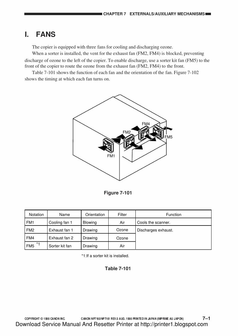
7/16/2019 Canon Np7161-Np7160 Copier Sm
http://slidepdf.com/reader/full/canon-np7161-np7160-copier-sm 169/345
COPYRIGHT © 1998 CANON INC. CANON NP7160/NP7161 REV.0 AUG. 1998 PRINTED IN JAPAN (IMPRIME AU JAPON) 7–1
CHAPTER 7 EXTERNALS/AUXILIARY MECHANISMS
I. FANS
The copier is equipped with three fans for cooling and discharging ozone.
When a sorter is installed, the vent for the exhaust fan (FM2, FM4) is blocked, preventing
discharge of ozone to the left of the copier. To enable discharge, use a sorter kit fan (FM5) to the
front of the copier to route the ozone from the exhaust fan (FM2, FM4) to the front.
Table 7-101 shows the function of each fan and the orientation of the fan. Figure 7-102
shows the timing at which each fan turns on.
FM1
FM2
FM4
FM5
Figure 7-101
Table 7-101
Notation Name Orientation Filter Function
FM1 Cooling fan 1 Blowing Cools the scanner.
*1
FM2 Exhaust fan 1 Drawing Discharges exhaust.
FM4 Exhaust fan 2 Drawing
Air
Ozone
Ozone
FM5 Sorter kit fan Drawing Air
*1:If a sorter kit is installed.
Download Service Manual And Resetter Printer at http://printer1.blogspot.com

7/16/2019 Canon Np7161-Np7160 Copier Sm
http://slidepdf.com/reader/full/canon-np7161-np7160-copier-sm 170/345
CHAPTER 7 EXTERNALS/AUXILIARY MECHANISMS
7–2 COPYRIGHT © 1998 CANON INC. CANON NP7160/NP7161 REV.0 AUG. 1998 PRINTED IN JAPAN (IMPRIME AU JAPON)
The exhaust fan (FM2) and the sorter kit fan (FM5) are rotated at half speed during standby
to prevent heating inside the machine. If the reading of the cleaner thermistor (TH3) is 50°C or
more (38°C or more if the sorter kit is installed), all fans will be rotated at full speed.
Sequence
Power switchON Power switchOFFStart keyON
WMUP WMUPR STBY INTR SCFW SCRV LSTR STBY
Cooling fan 1 (FM1)
*1
*1:If sorter kit is installed. : Full-speed rotation.
Exhaust fan 1 (FM2)
Exhaust fan 2 (FM4)
: Half-speed rotation.
Sorter kit fan (FM5)
Figure 7-102
The speed of the exhaust fans is switched between full speed and half speed by switching the
drive voltage of the exhaust fans as shown in Figure 7-103.
When the CPU generates FMON=1, +24 V is supplied so that the exhaust fans (FM2, FM4,FM5) rotate at full speed. In response to FMHLF=1, on the other hand, +15.4 V will be supplied
so that the exhaust fans (FM2, FM5) rotate at half speed.
FM
GA
FMHLF
FMON
+15.4v
+24v
DC controller PCB
Fan
FM-DRIVE
FM-DETECTGND
IC113
CPU
IC119
Figure 7-103
Download Service Manual And Resetter Printer at http://printer1.blogspot.com
7/16/2019 Canon Np7161-Np7160 Copier Sm
http://slidepdf.com/reader/full/canon-np7161-np7160-copier-sm 171/345
COPYRIGHT © 1998 CANON INC. CANON NP7160/NP7161 REV.0 AUG. 1998 PRINTED IN JAPAN (IMPRIME AU JAPON) 7–3
CHAPTER 7 EXTERNALS/AUXILIARY MECHANISMS
If the heat exhaust fan rotation detection signal (FM2ROT) is not detected 0.5 sec after the
exhaust fan (FM2, FM4) starts to rotate, error code E805 will be indicated on the control panel.
Download Service Manual And Resetter Printer at http://printer1.blogspot.com
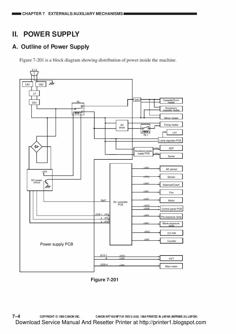
7/16/2019 Canon Np7161-Np7160 Copier Sm
http://slidepdf.com/reader/full/canon-np7161-np7160-copier-sm 172/345
CHAPTER 7 EXTERNALS/AUXILIARY MECHANISMS
7–4 COPYRIGHT © 1998 CANON INC. CANON NP7160/NP7161 REV.0 AUG. 1998 PRINTED IN JAPAN (IMPRIME AU JAPON)
II. POWER SUPPLY
A. Outline of Power Supply
Figure 7-201 is a block diagram showing distribution of power inside the machine.
Figure 7-201
Cassette/Drumheater
Accessorycassette heater
Mirror heater
Fixing heater
Accessory powersupply PCB
ACdriver
RMT
CB2CB1
LF
RLDS1
Sorter
AE sensor
Sensor
Fan
MotorDC controller
PCB
Power supply PCBCounter
HVT
Main motor
Blank-exposurelamp
CC-IVN
Solenoid/Clutch
Lamp regulator PCB
ADF
+24V
+24V
+24V
+24V
+5VU+24V
+24V
+24V
+24V
+24V
+5VU
+5VR
+5VU
+24V
+24V
+24V
LA1
SW1
Control panel PCB
+5VU
+5VR
+5VU
J208-1
-3
-4
J210-1
-8
J209-4
RL1
DC powercircuit
+24V
Pre-exposure lamp
Download Service Manual And Resetter Printer at http://printer1.blogspot.com
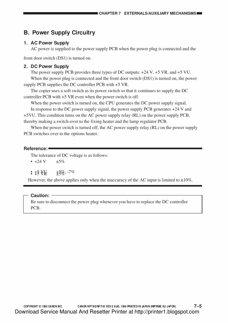
7/16/2019 Canon Np7161-Np7160 Copier Sm
http://slidepdf.com/reader/full/canon-np7161-np7160-copier-sm 173/345
COPYRIGHT © 1998 CANON INC. CANON NP7160/NP7161 REV.0 AUG. 1998 PRINTED IN JAPAN (IMPRIME AU JAPON) 7–5
CHAPTER 7 EXTERNALS/AUXILIARY MECHANISMS
B. Power Supply Circuitry
1. AC Power Supply
AC power is supplied to the power supply PCB when the power plug is connected and the
front door switch (DS1) is turned on.
2. DC Power Supply
The power supply PCB provides three types of DC outputs: +24 V, +5 VR, and +5 VU.
When the power plug is connected and the front door switch (DS1) is turned on, the power
supply PCB supplies the DC controller PCB with +5 VR.
The copier uses a soft switch as its power switch so that it continues to supply the DC
controller PCB with +5 VR even when the power switch is off.
When the power switch is turned on, the CPU generates the DC power supply signal.
In response to the DC power supply signal, the power supply PCB generates +24 V and
+5VU. This condition turns on the AC power supply relay (RL) on the power supply PCB,
thereby making a switch-over to the fixing heater and the lamp regulator PCB.
When the power switch is turned off, the AC power supply relay (RL) on the power supply
PCB switches over to the options heater.
Reference:
The tolerance of DC voltage is as follows:
• +24 V ±5%
• +5 VU +5%, -7%• +5 VR ±5%
However, the above applies only when the inaccuracy of the AC input is limited to ±10%.
Caution:
Be sure to disconnect the power plug whenever you have to replace the DC controller
PCB.
Download Service Manual And Resetter Printer at http://printer1.blogspot.com

7/16/2019 Canon Np7161-Np7160 Copier Sm
http://slidepdf.com/reader/full/canon-np7161-np7160-copier-sm 174/345
CHAPTER 7 EXTERNALS/AUXILIARY MECHANISMS
7–6 COPYRIGHT © 1998 CANON INC. CANON NP7160/NP7161 REV.0 AUG. 1998 PRINTED IN JAPAN (IMPRIME AU JAPON)
3. Mirror Heater, Cassette/Drum Heater, and Accessory Cassette Heater
The following three heaters are made available as accessories to the copier, designed to
prevent condensation of the scanner and the drum and to keep paper inside the cassette dry.
Table 7-201 shows the function of each heater. Figure 7-202 shows the timing at which each
heater turns on.
Notation Name Function
H2 Mirror heater Prevents condensation on the scanner.
Prevents condensation on the drum and keeps copy paper dry.
Keeps copy paper dry.
H3 Cassette/Drum heater
H4 Accessory cassette heater
Table 7-201
Sequence
Power switchON
Power switchOFF
Start keyON
WMUP WMUPR STBY INTR SCFW SCRV LSTR STBY
Mirror heater (H2)
Cassette/Drum heater (H3)
Accessory Cassette heater (H4)
Figure 7-202
Each heater is supplied with power when the copier’s power switch is turned off. The mirror
heater and the cassette/drum heater and the accessory cassette heater may be deprived of power
by turning off the heater switch (SW1).
4. ADF and Sorter
For the ADF and the sorter, the copier’s power supply PCB supplies AC power to the
accessory power supply PCB, which generates DC power.
Download Service Manual And Resetter Printer at http://printer1.blogspot.com
7/16/2019 Canon Np7161-Np7160 Copier Sm
http://slidepdf.com/reader/full/canon-np7161-np7160-copier-sm 175/345
COPYRIGHT © 1998 CANON INC. CANON NP7160/NP7161 REV.0 AUG. 1998 PRINTED IN JAPAN (IMPRIME AU JAPON) 7–7
CHAPTER 7 EXTERNALS/AUXILIARY MECHANISMS
C. Protection Mechanisms of the Power Supply Circuitry
The copier’s power supply PCB is equipped with a circuit breaker (CB1, CB2) and a fuse
(FU1, FU2) on its AC input side. To protect against overcurrent and over voltage, the copier is
also equipped with an overcurrent protection circuit and an over-voltage protection circuit.When an overcurrent or an over-voltage occurs as a result of a short circuit in the power line,
the respective protection mechanism will turn on to stop the output of the power supply PCB.
When the output is stopped, disconnect the copier’s power plug, and turn off the AC power
to the power supply PCB to reset the protection mechanism.
Caution:
Be sure to correct the cause that turned on the protection circuit before resetting.
Repeated short-circuiting and resetting can cause the fuse built into the power supply
PCB to melt.
Download Service Manual And Resetter Printer at http://printer1.blogspot.com

7/16/2019 Canon Np7161-Np7160 Copier Sm
http://slidepdf.com/reader/full/canon-np7161-np7160-copier-sm 176/345
CHAPTER 7 EXTERNALS/AUXILIARY MECHANISMS
7–8 COPYRIGHT © 1998 CANON INC. CANON NP7160/NP7161 REV.0 AUG. 1998 PRINTED IN JAPAN (IMPRIME AU JAPON)
III. DISASSEMBLY/ASSEMBLY
The copier may be disassembled and assembled as shown here. Pay attention to the copier’s
mechanical characteristics along with the steps for disassembly/assembly.
Important:
1. Turn off the power and disconnect the power plug to ensure safety whenever
disassembling/assembling the copier.
2. Unless otherwise noted, assemble the parts by reversing the steps used to disassemble
them.
3. Identify the screws by type (length, diameter) to avoid use in the wrong location.
4. Use a washer where needed. The mounting screws used for the grounding wire and
varistor come with a washer to ensure electric continuity. Do not forget to use these
washers.5. As a rule, do not operate the copier with any of its parts removed.
Download Service Manual And Resetter Printer at http://printer1.blogspot.com
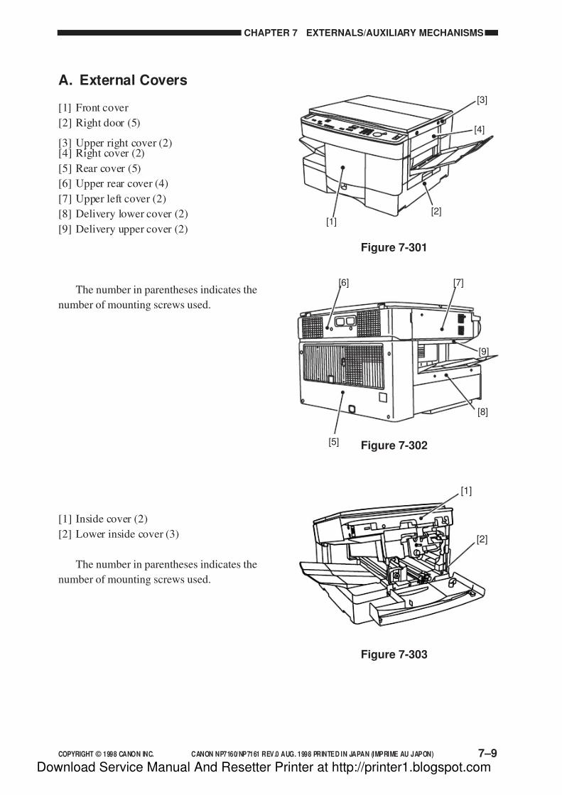
7/16/2019 Canon Np7161-Np7160 Copier Sm
http://slidepdf.com/reader/full/canon-np7161-np7160-copier-sm 177/345
COPYRIGHT © 1998 CANON INC. CANON NP7160/NP7161 REV.0 AUG. 1998 PRINTED IN JAPAN (IMPRIME AU JAPON) 7–9
CHAPTER 7 EXTERNALS/AUXILIARY MECHANISMS
A. External Covers
[1] Front cover
[2] Right door (5)
[3] Upper right cover (2)[4] Right cover (2)
[5] Rear cover (5)
[6] Upper rear cover (4)
[7] Upper left cover (2)
[8] Delivery lower cover (2)
[9] Delivery upper cover (2)
The number in parentheses indicates the
number of mounting screws used.
[1] Inside cover (2)
[2] Lower inside cover (3)
The number in parentheses indicates the
number of mounting screws used.
Figure 7-301
[1]
[2]
Figure 7-303
Figure 7-302
[1][2]
[4]
[3]
[5]
[6] [7]
[8]
[9]
Download Service Manual And Resetter Printer at http://printer1.blogspot.com

7/16/2019 Canon Np7161-Np7160 Copier Sm
http://slidepdf.com/reader/full/canon-np7161-np7160-copier-sm 178/345
CHAPTER 7 EXTERNALS/AUXILIARY MECHANISMS
7–10 COPYRIGHT © 1998 CANON INC. CANON NP7160/NP7161 REV.0 AUG. 1998 PRINTED IN JAPAN (IMPRIME AU JAPON)
Remove the appropriate covers as follows
when cleaning, checking, or repairing the
inside of the copier.
Covers which may be detached by mere
removal of mounting screws are omitted fromthe discussions.
1. Removing the Right Door
1) Open the right door.
2) Remove the four mounting screws [1],
and remove the right door [2] and the
paper guide [3].
Caution:When mounting the paper guide, be
sure to fit the foot of the spring [4] at
the rear into its hole.
2. Removing the Upper Right Cover
1) Open the top unit.
2) Remove the two mounting screws [1], and
remove the right cover [2].
3) Remove the two mounting screws [3], andremove the upper right cover [4].
[4]
[3]
[2] [1]
Figure 7-304
[1]
[2]
[3]
[4]
Figure 7-305
Download Service Manual And Resetter Printer at http://printer1.blogspot.com

7/16/2019 Canon Np7161-Np7160 Copier Sm
http://slidepdf.com/reader/full/canon-np7161-np7160-copier-sm 179/345
COPYRIGHT © 1998 CANON INC. CANON NP7160/NP7161 REV.0 AUG. 1998 PRINTED IN JAPAN (IMPRIME AU JAPON) 7–11
CHAPTER 7 EXTERNALS/AUXILIARY MECHANISMS
Figure 7-306
[ 2][1 ]
Figure 7-307
[2]
Figure 7-308
3. Removing the Upper Left Cover
1) Remove the copyboard glass.
2) Remove the two mounting screws [1], and
detach the upper left cover [2].
4. Removing the Delivery LowerCover
1) Open the copier top, and remove the copy
tray.
2) Remove the two mounting screws [1], and
detach the delivery lower cover [2].
5. Removing the Delivery UpperCover
1) Open the copier top, and remove the
inside cover.
2) Remove the two mounting screws [1], andslide the delivery upper cover [2] to the
front to remove.
Caution:
When mounting the delivery upper
cover, be sure to engage the two cut-
offs in the delivery upper cover with
the copier’s hooks.
[2] [1]
Download Service Manual And Resetter Printer at http://printer1.blogspot.com

7/16/2019 Canon Np7161-Np7160 Copier Sm
http://slidepdf.com/reader/full/canon-np7161-np7160-copier-sm 180/345
CHAPTER 7 EXTERNALS/AUXILIARY MECHANISMS
7–12 COPYRIGHT © 1998 CANON INC. CANON NP7160/NP7161 REV.0 AUG. 1998 PRINTED IN JAPAN (IMPRIME AU JAPON)
6. Removing the Lower Inside Cover
1) Remove the front door and the transfer
charging assembly.
2) Slide out the registration knob [1] to the
front.3) Remove the mounting screw [2].
4) Loosen the two mounting screws [3], and
remove the lower inside cover [4].
Figure 7-309
[ 1 ] [ 4 ]
[2 ]
[3 ]
Download Service Manual And Resetter Printer at http://printer1.blogspot.com
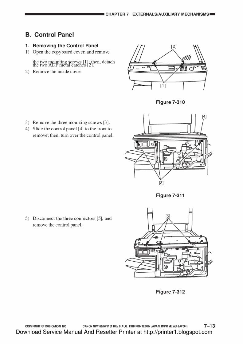
7/16/2019 Canon Np7161-Np7160 Copier Sm
http://slidepdf.com/reader/full/canon-np7161-np7160-copier-sm 181/345
COPYRIGHT © 1998 CANON INC. CANON NP7160/NP7161 REV.0 AUG. 1998 PRINTED IN JAPAN (IMPRIME AU JAPON) 7–13
CHAPTER 7 EXTERNALS/AUXILIARY MECHANISMS
[2]
[1]
[5]
[3]
[4]
Figure 7-311
Figure 7-312
Figure 7-310
B. Control Panel
1. Removing the Control Panel
1) Open the copyboard cover, and remove
the two mounting screws [1]; then, detachthe two ADF metal catches [2].
2) Remove the inside cover.
5) Disconnect the three connectors [5], and
remove the control panel.
3) Remove the three mounting screws [3].
4) Slide the control panel [4] to the front to
remove; then, turn over the control panel.
Download Service Manual And Resetter Printer at http://printer1.blogspot.com

7/16/2019 Canon Np7161-Np7160 Copier Sm
http://slidepdf.com/reader/full/canon-np7161-np7160-copier-sm 182/345
CHAPTER 7 EXTERNALS/AUXILIARY MECHANISMS
7–14 COPYRIGHT © 1998 CANON INC. CANON NP7160/NP7161 REV.0 AUG. 1998 PRINTED IN JAPAN (IMPRIME AU JAPON)
[1]
[2]
Figure 7-313
Figure 7-314
[4]
[5]
[3]
C. Copyboard Glass
1. Removing the Copyboard Glass
1) Remove the two mounting screws [1], and
detach the glass retainer (right) [2].
2) Slide the copyboard glass [3] to the right.
3) Remove the two mounting screws [4], and
detach the glass retainer (left) [5].
4) Remove the copyboard glass [3].
Caution:
When mounting the NP7161’s
copyboard glass, make sure that the
blue marking on the side of the glass
is to the front left.
Download Service Manual And Resetter Printer at http://printer1.blogspot.com

7/16/2019 Canon Np7161-Np7160 Copier Sm
http://slidepdf.com/reader/full/canon-np7161-np7160-copier-sm 183/345
COPYRIGHT © 1998 CANON INC. CANON NP7160/NP7161 REV.0 AUG. 1998 PRINTED IN JAPAN (IMPRIME AU JAPON) 7–15
CHAPTER 7 EXTERNALS/AUXILIARY MECHANISMS
D. Fans
1. Removing the Scanner Cooling Fan
1) Remove the two mounting screws [1], and
detach the filter [2].
[2]
[1]
[ 3]
[ 4]
Figure 7-316
Figure 7-315
2) Disconnect the connector [3], and remove
the scanner cooling fan [4].
Download Service Manual And Resetter Printer at http://printer1.blogspot.com
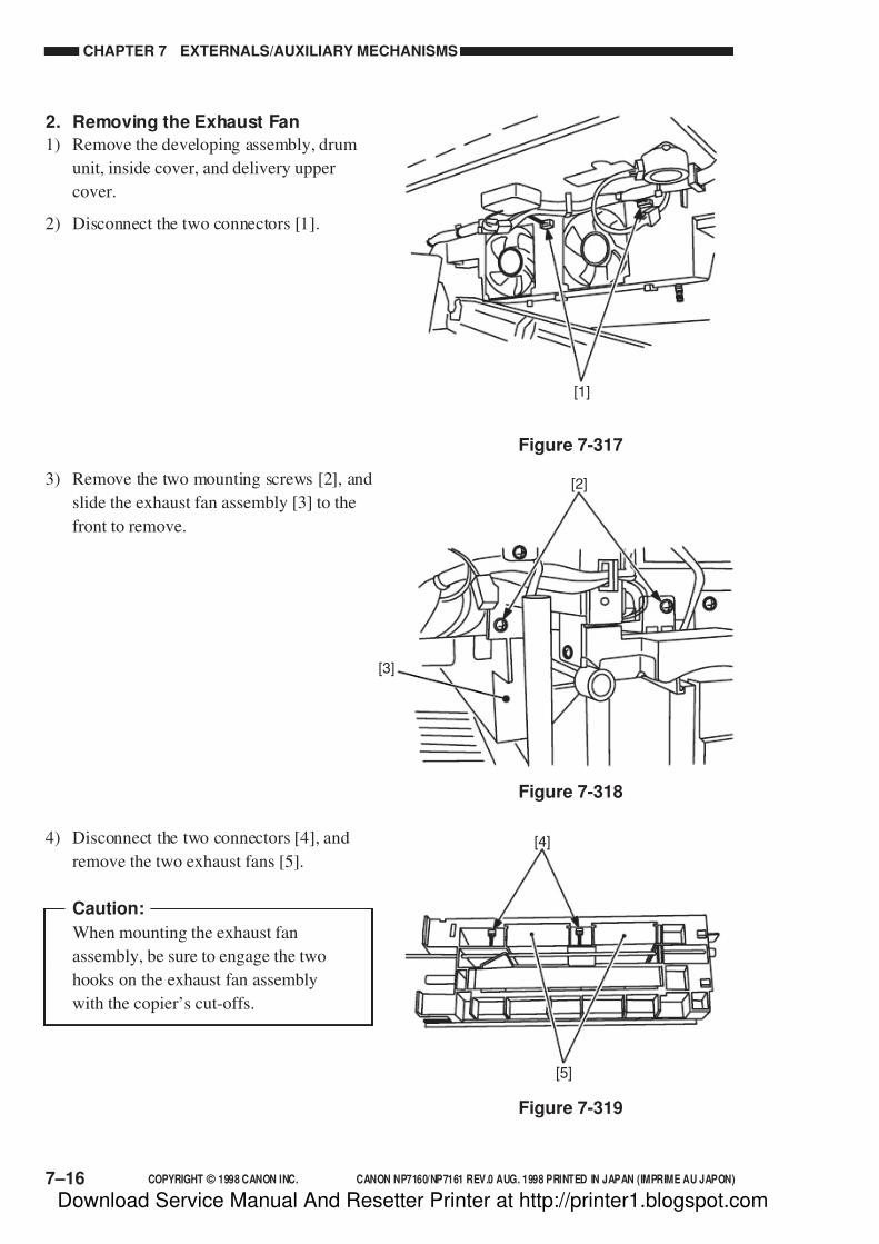
7/16/2019 Canon Np7161-Np7160 Copier Sm
http://slidepdf.com/reader/full/canon-np7161-np7160-copier-sm 184/345
CHAPTER 7 EXTERNALS/AUXILIARY MECHANISMS
7–16 COPYRIGHT © 1998 CANON INC. CANON NP7160/NP7161 REV.0 AUG. 1998 PRINTED IN JAPAN (IMPRIME AU JAPON)
[1]
Figure 7-317
[2]
[3]
Figure 7-318
[4]
[5]
Figure 7-319
2. Removing the Exhaust Fan
1) Remove the developing assembly, drum
unit, inside cover, and delivery upper
cover.
2) Disconnect the two connectors [1].
3) Remove the two mounting screws [2], and
slide the exhaust fan assembly [3] to the
front to remove.
4) Disconnect the two connectors [4], and
remove the two exhaust fans [5].
Caution:
When mounting the exhaust fan
assembly, be sure to engage the two
hooks on the exhaust fan assembly
with the copier’s cut-offs.
Download Service Manual And Resetter Printer at http://printer1.blogspot.com

7/16/2019 Canon Np7161-Np7160 Copier Sm
http://slidepdf.com/reader/full/canon-np7161-np7160-copier-sm 185/345
COPYRIGHT © 1998 CANON INC. CANON NP7160/NP7161 REV.0 AUG. 1998 PRINTED IN JAPAN (IMPRIME AU JAPON) 7–17
CHAPTER 7 EXTERNALS/AUXILIARY MECHANISMS
3. Remove the Ozone Filter
1) Open the top unit.
2) Shift down the lever [1], and remove the
ozone filter assembly [2].
3) Remove the ozone filter [3].
[2] [1]
Figure 7-320
[3]
Figure 7-321
Download Service Manual And Resetter Printer at http://printer1.blogspot.com

7/16/2019 Canon Np7161-Np7160 Copier Sm
http://slidepdf.com/reader/full/canon-np7161-np7160-copier-sm 186/345
CHAPTER 7 EXTERNALS/AUXILIARY MECHANISMS
7–18 COPYRIGHT © 1998 CANON INC. CANON NP7160/NP7161 REV.0 AUG. 1998 PRINTED IN JAPAN (IMPRIME AU JAPON)
[4]
[3][5][2]
[1]
Figure 7-322
[4]
[2]
[1]
[3]
Figure 7-323
E. Counter Assembly
1. Removing the Counter Assembly
1) Remove the control panel.
2) Remove the two mounting screws [1], andremove the magnet [2].
3) Disconnect the two connectors [3], and
remove the two mounting screws [4];
then, detach the counter assembly [5].
Caution:
When removing the magnet, mark its
position and mount it with reference
to the markings.
F. Main Motor Assembly
1. Removing the Main MotorAssembly
1) Remove the rear cover and the rear upper
cover.
2) Disconnect the connector [1], and remove
the four mounting screws [2].
3) Remove the two locking supports [3], anddetach the main motor assembly [4].
Download Service Manual And Resetter Printer at http://printer1.blogspot.com

7/16/2019 Canon Np7161-Np7160 Copier Sm
http://slidepdf.com/reader/full/canon-np7161-np7160-copier-sm 187/345
COPYRIGHT © 1998 CANON INC. CANON NP7160/NP7161 REV.0 AUG. 1998 PRINTED IN JAPAN (IMPRIME AU JAPON) 7–19
CHAPTER 7 EXTERNALS/AUXILIARY MECHANISMS
G. DC Controller PCB
1. Removing the DC Controller PCB
1) Remove the delivery lower cover.
2) Disconnect all connectors of the DCcontroller PCB; then, free the harness
from the harness guide.
3) Remove the six mounting screws [1], and
remove the DC controller PCB [2]
together with the base plate.
Caution:
Take extra care not to damage the
harness whenever you are removing
the DC controller PCB.
The DC controller PCB is equipped with
a built-in battery (BAT101). Keep the
following in mind to prevent its both ends
from short circuiting and heating:
2. Points to Note When Replacing theDC Controller PCB
• When sending the DC controller to theworkshop or the factory, put it in a
conducting bag intact with its base
plate.
Use a conducting bag whose one side is
transparent, and be sure that the face of
the DC controller PCB shows through
the transparent side.
• After replacement, make adjustments
and settings in service mode and makesettings in user mode once again.
• For settings in service mode, enter the
values recorded in the Service Label
stored behind the front door.
Figure 7-324
[2]
[1]
Download Service Manual And Resetter Printer at http://printer1.blogspot.com
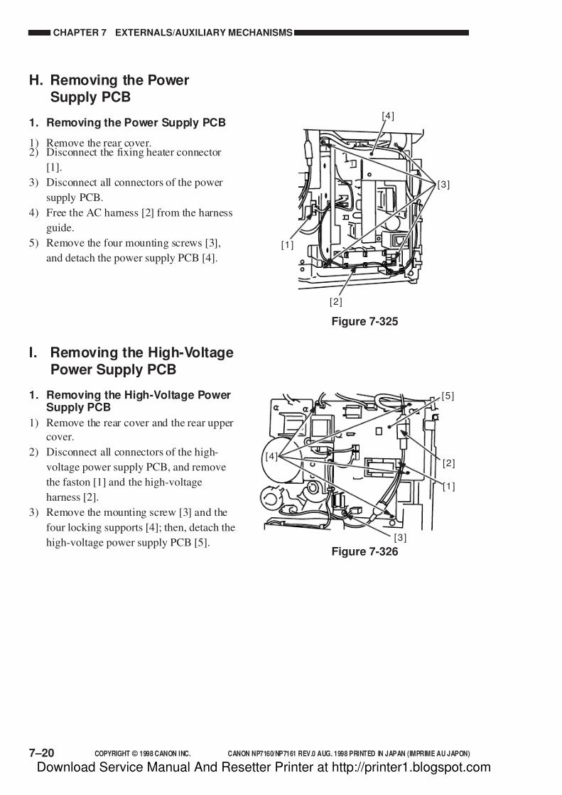
7/16/2019 Canon Np7161-Np7160 Copier Sm
http://slidepdf.com/reader/full/canon-np7161-np7160-copier-sm 188/345
CHAPTER 7 EXTERNALS/AUXILIARY MECHANISMS
7–20 COPYRIGHT © 1998 CANON INC. CANON NP7160/NP7161 REV.0 AUG. 1998 PRINTED IN JAPAN (IMPRIME AU JAPON)
Figure 7-325
[4 ]
[3 ]
[1 ]
[ 2 ]
H. Removing the PowerSupply PCB
1. Removing the Power Supply PCB
1) Remove the rear cover.2) Disconnect the fixing heater connector
[1].
3) Disconnect all connectors of the power
supply PCB.
4) Free the AC harness [2] from the harness
guide.
5) Remove the four mounting screws [3],
and detach the power supply PCB [4].
I. Removing the High-VoltagePower Supply PCB
1. Removing the High-Voltage PowerSupply PCB
1) Remove the rear cover and the rear upper
cover.
2) Disconnect all connectors of the high-
voltage power supply PCB, and remove
the faston [1] and the high-voltage
harness [2].
3) Remove the mounting screw [3] and the
four locking supports [4]; then, detach the
high-voltage power supply PCB [5].
[ 4][2 ]
[ 5 ]
[1 ]
[ 3 ]
Figure 7-326
Download Service Manual And Resetter Printer at http://printer1.blogspot.com

7/16/2019 Canon Np7161-Np7160 Copier Sm
http://slidepdf.com/reader/full/canon-np7161-np7160-copier-sm 189/345
COPYRIGHT © 1998 CANON INC. CANON NP7160/NP7161 REV.0 AUG. 1998 PRINTED IN JAPAN (IMPRIME AU JAPON) 7–21
CHAPTER 7 EXTERNALS/AUXILIARY MECHANISMS
[2]
[3]
[1]
Figure 7-327
J. Lamp Regulator PCB
1. Removing the Lamp Regulator PCB
1) Remove the rear cover.
2) Disconnect the two connectors [1] of thelamp regulator PCB.
3) Remove the three locking supports [2],
and detach the lamp regulator PCB [3].
Download Service Manual And Resetter Printer at http://printer1.blogspot.com

7/16/2019 Canon Np7161-Np7160 Copier Sm
http://slidepdf.com/reader/full/canon-np7161-np7160-copier-sm 190/345
Download Service Manual And Resetter Printer at http://printer1.blogspot.com

7/16/2019 Canon Np7161-Np7160 Copier Sm
http://slidepdf.com/reader/full/canon-np7161-np7160-copier-sm 191/345
COPYRIGHT © 1998 CANON INC. CANON NP7161/NP7160 REV.0 AUG. 1998 PRINTED IN JAPAN (IMPRIME AU JAPON)
CHAPTER 8
INSTALLATION
This chapter introduces requirements for the site of installation, and shows how the copier may be
installed using step-by-step instructions.
I. SELECTING THE SITE ............................ 8-1II. UNPACKING AND INSTALLATION ........ 8-2
A. Unpacking .......................................... 8-2
B. Removing the Metal Fixings............... 8-3
C. Mounting the Drum Unit ..................... 8-4D. Cleaning the Parts and Making Checks .. 8-6
E. Checking the Images/Operations andUser Mode .......................................... 8-8
F. Supplying Toner ............................... 8-10III. RELOCATING THE MACHINE .............. 8-12
IV. INSTALLING THE CONTROL
CARD IV N ............................................. 8-13V. INSTALLING THE REMOTE
DIAGNOSTIC DEVICE II .......................... 8-14
VI. INSTALLING THE ACCESSORYCOUNTER ................................................ 8-23
VII. INSTALLING THE ACCESSORY
HEATER ................................................. 8-25
A. Installing the Heater Switch ............. 8-25B. Mounting the Cassette/Drum Heater 8-26
C. Installing the Mirror Heater ............... 8-27
Download Service Manual And Resetter Printer at http://printer1.blogspot.com

7/16/2019 Canon Np7161-Np7160 Copier Sm
http://slidepdf.com/reader/full/canon-np7161-np7160-copier-sm 192/345
Download Service Manual And Resetter Printer at http://printer1.blogspot.com

7/16/2019 Canon Np7161-Np7160 Copier Sm
http://slidepdf.com/reader/full/canon-np7161-np7160-copier-sm 193/345
COPYRIGHT © 1998 CANON INC. CANON NP7161/NP7160 REV.0 AUG. 1998 PRINTED IN JAPAN (IMPRIME AU JAPON) 8–1
CHAPTER 8 INSTALLATION
I. SELECTING THE SITE
Check the site of installation against the following requirements. If possible, visit the site in
advance of the delivery of the machine.
1. There must be a dedicated power outlet for exclusive use by the copier capable of providing
the rated voltage (±10%).
2. The temperature must be 7.5° to 32.5°C (45.5° to 90.5°F), and humidity must be 5% to 85%
RH. (Avoid areas near a water faucet, water boiler, humidifier, and refrigerator.)
3. Avoid areas near a source of fire and areas subject to dust or ammonia gas. Avoid direct rays
of the sun. As necessary, provide curtains.
4. The amount of ozone generated by the copier is of a level not affecting the health of the
individuals around it. Some individuals, however, may find its smell unpleasant. Be sure that
the room is properly ventilated.
5. Select a well-ventilated area. If multiple copiers are to be installed, in particular, make surethat the exhaust from one will not be drawn into the vent of another.
6. Make sure that the copier will be level.
7. Keep the copier 10 cm (3.9 in) or more away from any wall to provide adequate space for
machine operation.
10cm/3.9in.min.
50cm/19.7in.min.
50cm/19.7in.min.
50cm/19.7in.min.
Figure 8-101
Download Service Manual And Resetter Printer at http://printer1.blogspot.com

7/16/2019 Canon Np7161-Np7160 Copier Sm
http://slidepdf.com/reader/full/canon-np7161-np7160-copier-sm 194/345
CHAPTER 8 INSTALLATION
8–2 COPYRIGHT © 1998 CANON INC. CANON NP7161/NP7160 REV.0 AUG. 1998 PRINTED IN JAPAN (IMPRIME AU JAPON)
Step Work Checks/remarks
Open the shipping box, and take out
the two cardboard boxes.
1
Check to make sure that none of the following ismissing:
• copy tray• power cord• drum unit• User’s Manual• waste toner case (3 pc.)• waste toner case bag (4 pc.)• top unit close label
Open the cardboard boxes, and takeout the attachments.
2
II. UNPACKING AND INSTALLATION
When a piece of metal is brought in from a cold to warm place, droplets of water tend to
form on its surface. This phenomenon is known as condensation, and copiers suffering from
condensation can generate blank copies.
If the copier has been brought in from a cold place, keep it unpacked for one hour or more
before starting the installation work.
The copier weighs about 42 kg/92.4 lb. Be sure to work in a group of two when lifting it.
A. Unpacking
Holding the grips at the bottom (bothsides), move the copier to the site of installation.
3
Grips
Grips
Download Service Manual And Resetter Printer at http://printer1.blogspot.com

7/16/2019 Canon Np7161-Np7160 Copier Sm
http://slidepdf.com/reader/full/canon-np7161-np7160-copier-sm 195/345
COPYRIGHT © 1998 CANON INC. CANON NP7161/NP7160 REV.0 AUG. 1998 PRINTED IN JAPAN (IMPRIME AU JAPON) 8–3
CHAPTER 8 INSTALLATION
B. Removing the Metal Fixings
Step Work Checks/remarks
Remove the packing tape, cushioningmaterial, protective sheet of thecopyboard glass, and protective sheetof the size index.
Slide out the cassette, and remove thepacking tape and the cushioningmaterial from inside.
Slide the cassette into the copier.
Remove the two scanner fixing screws
from the copier’s left side. (Storeaway the scanner fixing screw forpossible relocation of the machine.)
Open the front door, and shift up theopening/closing lever to open thecopier top.
Remove the metal fixing from theopening/closing hook (right). (Youwill not be using the removed metalfixing.)
While opening the delivery assembly,
remove the fixing assembly releasingplate (1 each at front and rear). (Youwill not be using the removed fixingassembly releasing plate.)
Check to make sure that the covers are free of scratches and dents.
1
2
4
3
5
6
Scanner fixingscrews
Pressurerelease plate (rear)
Pressure
release plate (front)
Fixingdeliveryassembly
Main unit lever
Cushioning material
Download Service Manual And Resetter Printer at http://printer1.blogspot.com
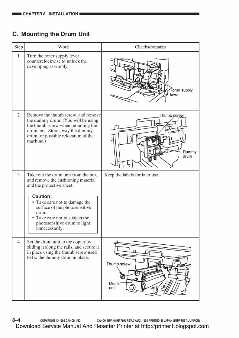
7/16/2019 Canon Np7161-Np7160 Copier Sm
http://slidepdf.com/reader/full/canon-np7161-np7160-copier-sm 196/345
CHAPTER 8 INSTALLATION
8–4 COPYRIGHT © 1998 CANON INC. CANON NP7161/NP7160 REV.0 AUG. 1998 PRINTED IN JAPAN (IMPRIME AU JAPON)
Turn the toner supply levercounterclockwise to unlock thedeveloping assembly.
Remove the thumb screw, and removethe dummy drum. (You will be usingthe thumb screw when mounting thedrum unit. Store away the dummydrum for possible relocation of themachine.)
1
2
C. Mounting the Drum Unit
Take out the drum unit from the box,and remove the cushioning materialand the protective sheet.
Caution:• Take care not to damage the
surface of the photosensitivedrum.
• Take care not to subject thephotosensitive drum to lightunnecessarily.
3 Keep the labels for later use.
Dummydrum
Thumb screw
Step Work Checks/remarks
Set the drum unit to the copier bysliding it along the rails, and secure itin place using the thumb screw usedto fix the dummy drum in place.
4
Drumunit
Thumb screw
Toner supplylever
Download Service Manual And Resetter Printer at http://printer1.blogspot.com
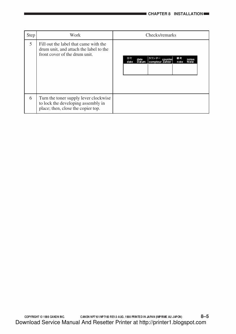
7/16/2019 Canon Np7161-Np7160 Copier Sm
http://slidepdf.com/reader/full/canon-np7161-np7160-copier-sm 197/345
COPYRIGHT © 1998 CANON INC. CANON NP7161/NP7160 REV.0 AUG. 1998 PRINTED IN JAPAN (IMPRIME AU JAPON) 8–5
CHAPTER 8 INSTALLATION
Fill out the label that came with thedrum unit, and attach the label to thefront cover of the drum unit.
5
Step Work Checks/remarks
Turn the toner supply lever clockwiseto lock the developing assembly inplace; then, close the copier top.
6
datedate Datum
countercompteur Zahler
notesnote Notiz
Download Service Manual And Resetter Printer at http://printer1.blogspot.com
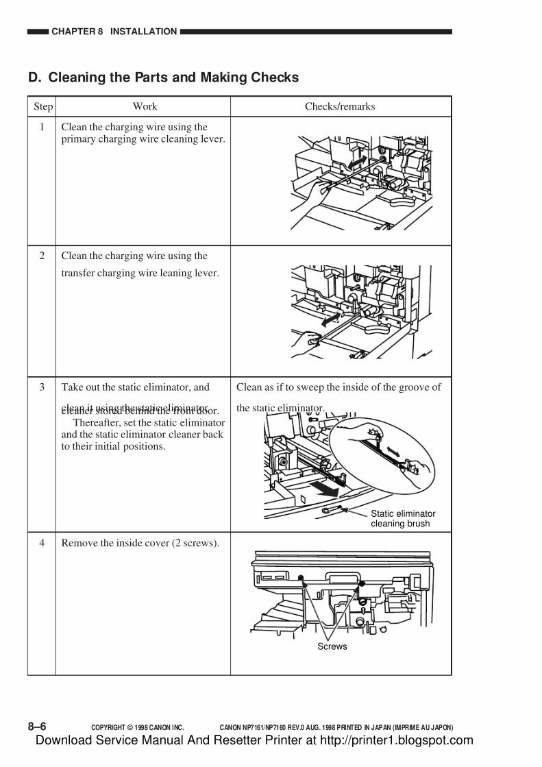
7/16/2019 Canon Np7161-Np7160 Copier Sm
http://slidepdf.com/reader/full/canon-np7161-np7160-copier-sm 198/345
CHAPTER 8 INSTALLATION
8–6 COPYRIGHT © 1998 CANON INC. CANON NP7161/NP7160 REV.0 AUG. 1998 PRINTED IN JAPAN (IMPRIME AU JAPON)
Clean the charging wire using theprimary charging wire cleaning lever.
1
Clean the charging wire using the
transfer charging wire leaning lever.
2
Clean as if to sweep the inside of the groove of
the static eliminator.
Take out the static eliminator, and
clean it using the static eliminatorcleaner stored behind the front door.Thereafter, set the static eliminator
and the static eliminator cleaner back to their initial positions.
3
D. Cleaning the Parts and Making Checks
Step Work Checks/remarks
Remove the inside cover (2 screws).4
Screws
Static eliminatorcleaning brush
Download Service Manual And Resetter Printer at http://printer1.blogspot.com
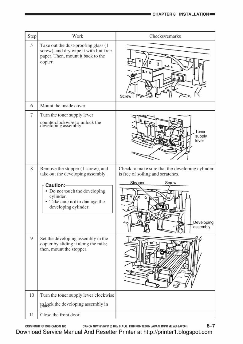
7/16/2019 Canon Np7161-Np7160 Copier Sm
http://slidepdf.com/reader/full/canon-np7161-np7160-copier-sm 199/345
COPYRIGHT © 1998 CANON INC. CANON NP7161/NP7160 REV.0 AUG. 1998 PRINTED IN JAPAN (IMPRIME AU JAPON) 8–7
CHAPTER 8 INSTALLATION
Take out the dust-proofing glass (1screw), and dry wipe it with lint-freepaper. Then, mount it back to the
copier.
5
Mount the inside cover.6
Turn the toner supply lever
counterclockwise to unlock thedeveloping assembly.
7
Screw
Remove the stopper (1 screw), andtake out the developing assembly.
Caution:• Do not touch the developing
cylinder.• Take care not to damage the
developing cylinder.
8 Check to make sure that the developing cylinderis free of soiling and scratches.
Step Work Checks/remarks
Set the developing assembly in thecopier by sliding it along the rails;then, mount the stopper.
9
Turn the toner supply lever clockwise
to lock the developing assembly inplace.
10
Stopper Screw
Developingassembly
Close the front door.11
Tonersupplylever
Download Service Manual And Resetter Printer at http://printer1.blogspot.com

7/16/2019 Canon Np7161-Np7160 Copier Sm
http://slidepdf.com/reader/full/canon-np7161-np7160-copier-sm 200/345
CHAPTER 8 INSTALLATION
8–8 COPYRIGHT © 1998 CANON INC. CANON NP7161/NP7160 REV.0 AUG. 1998 PRINTED IN JAPAN (IMPRIME AU JAPON)
E. Checking the Images/Operations and User Mode
Connect the power cord to the copier,and connect the power plug to theoutlet.
1
Step Work Checks/remarks
• This mode lasts about 4 min.• While this mode is effective, ‘401’ is
indicated; upon completion, ‘4’ of ‘401’ isflashed.
Caution:While the mode remains on, do not turn off the power or open the front door.
In standby state, execute service mode401 (stir toner).
Steps
1) Press the User mode key.
2) Hold down ‘2’ and ‘8’ on the
numeric keypad at the same time
for 0.5 sec or more.
3) Press the user mode key.
4) Check to see that ‘1’ is indicated.
5) Press ‘4’ on the numeric keypad.6) Check to see that ‘4’ is indicated.
7) Press the AE key.
8) Check to make sure that ‘401’ is
indicated.
9) Press the Start key to start
stirring toner.
4
Turn on the power switch.2 • Check to make sure that the Paper indicatorflashes.
• Press the keys on the numeric keypad andthe Clear key to make sure that copy countsare indicated correctly.
Supply toner.3 See F. “Supplying Toner.”
• This mode lasts about 40 sec.
• While this mode is effective, ‘403’ isindicated; upon completion, ‘4’ of ‘403’ isflashed.
Caution:While the mode remains on, do not turn off the power or open the front door.
Execute service mode 403 drum unit
installation mode.
Steps
1) Check to see that ‘401’ is
indicated.
2) Press ‘3’ on the numeric keypad.
3) Check to see that ‘403’ is
indicated.
4) Press the Start key to start drum
unit installation mode.
5
Download Service Manual And Resetter Printer at http://printer1.blogspot.com
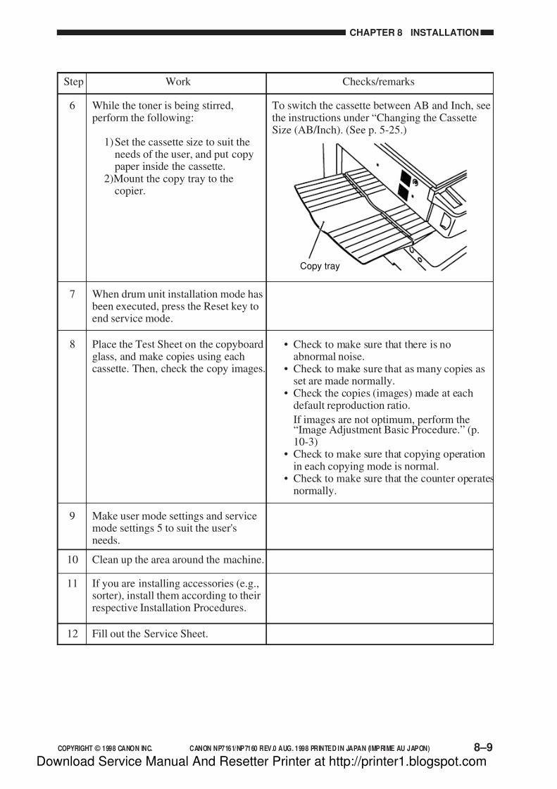
7/16/2019 Canon Np7161-Np7160 Copier Sm
http://slidepdf.com/reader/full/canon-np7161-np7160-copier-sm 201/345
COPYRIGHT © 1998 CANON INC. CANON NP7161/NP7160 REV.0 AUG. 1998 PRINTED IN JAPAN (IMPRIME AU JAPON) 8–9
CHAPTER 8 INSTALLATION
Step Work Checks/remarks
When drum unit installation mode hasbeen executed, press the Reset key toend service mode.
7
While the toner is being stirred,perform the following:
1)Set the cassette size to suit theneeds of the user, and put copypaper inside the cassette.
2)Mount the copy tray to thecopier.
6 To switch the cassette between AB and Inch, seethe instructions under “Changing the CassetteSize (AB/Inch). (See p. 5-25.)
Copy tray
Place the Test Sheet on the copyboardglass, and make copies using eachcassette. Then, check the copy images.
8 • Check to make sure that there is noabnormal noise.
• Check to make sure that as many copies asset are made normally.
• Check the copies (images) made at eachdefault reproduction ratio.
If images are not optimum, perform the“Image Adjustment Basic Procedure.” (p.10-3)
• Check to make sure that copying operationin each copying mode is normal.
• Check to make sure that the counter operatesnormally.
Fill out the Service Sheet.
If you are installing accessories (e.g.,sorter), install them according to theirrespective Installation Procedures.
Clean up the area around the machine.10
11
12
Make user mode settings and servicemode settings 5 to suit the user'sneeds.
9
Download Service Manual And Resetter Printer at http://printer1.blogspot.com
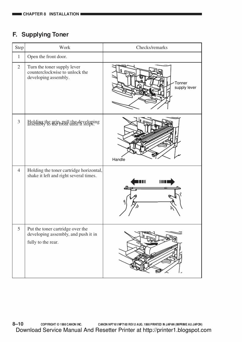
7/16/2019 Canon Np7161-Np7160 Copier Sm
http://slidepdf.com/reader/full/canon-np7161-np7160-copier-sm 202/345
CHAPTER 8 INSTALLATION
8–10 COPYRIGHT © 1998 CANON INC. CANON NP7161/NP7160 REV.0 AUG. 1998 PRINTED IN JAPAN (IMPRIME AU JAPON)
F. Supplying Toner
Open the front door.1
Holding the toner cartridge horizontal,shake it left and right several times.
4
Put the toner cartridge over thedeveloping assembly, and push it in
fully to the rear.
5
Holding the grip, pull the developingassembly to the front until it stops.3
Turn the toner supply levercounterclockwise to unlock thedeveloping assembly.
2
Handle
Step Work Checks/remarks
Tonnersupply lever
Download Service Manual And Resetter Printer at http://printer1.blogspot.com
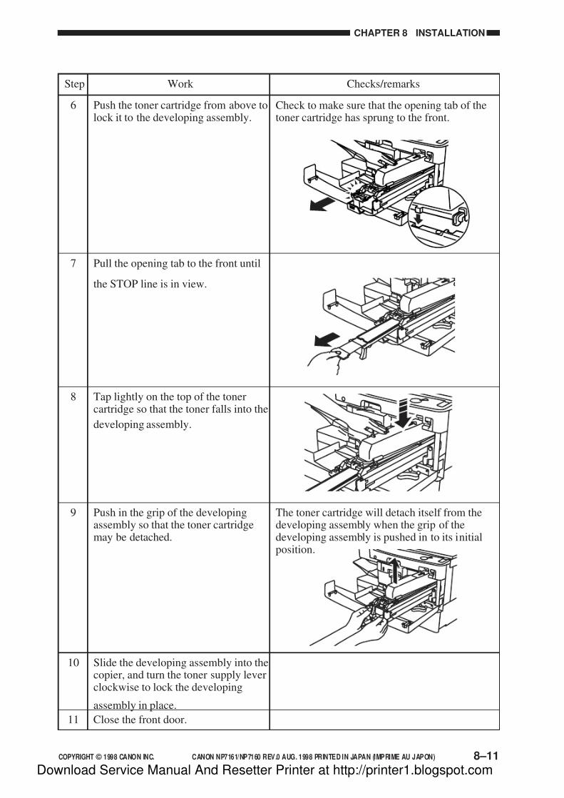
7/16/2019 Canon Np7161-Np7160 Copier Sm
http://slidepdf.com/reader/full/canon-np7161-np7160-copier-sm 203/345
COPYRIGHT © 1998 CANON INC. CANON NP7161/NP7160 REV.0 AUG. 1998 PRINTED IN JAPAN (IMPRIME AU JAPON) 8–11
CHAPTER 8 INSTALLATION
The toner cartridge will detach itself from thedeveloping assembly when the grip of thedeveloping assembly is pushed in to its initialposition.
Slide the developing assembly into thecopier, and turn the toner supply leverclockwise to lock the developing
assembly in place.
10
Push in the grip of the developingassembly so that the toner cartridgemay be detached.
9
Check to make sure that the opening tab of thetoner cartridge has sprung to the front.
Push the toner cartridge from above tolock it to the developing assembly.
6
Pull the opening tab to the front until
the STOP line is in view.
7
Tap lightly on the top of the tonercartridge so that the toner falls into the
developing assembly.
8
Step Work Checks/remarks
Close the front door.11
Download Service Manual And Resetter Printer at http://printer1.blogspot.com

7/16/2019 Canon Np7161-Np7160 Copier Sm
http://slidepdf.com/reader/full/canon-np7161-np7160-copier-sm 204/345
CHAPTER 8 INSTALLATION
8–12 COPYRIGHT © 1998 CANON INC. CANON NP7161/NP7160 REV.0 AUG. 1998 PRINTED IN JAPAN (IMPRIME AU JAPON)
Make a copy in Direct.
Take out all copy paper from thecassette.
Excute ‘403’ in service mode.The scanner, lens, and No.4/No.5mirror unit move to the position for
transportation.
Turn off the power switch, anddisconnect the power plug from thepower outlet.
Secure the scanner in place using thetwo scanner fixing screws from theleft side of the copier.
Take out the drum unit, and mount thedummy drum.
Remove the copy tray.
Tape the front door, multifeeder tray,and cassette in place.
Place A3 copy paper on thecopyboard glass, and tape thecopyboard in place.
1
2
3
4
5
6
7
8
9
The drum unit must betransported separately.
Use the screwsremoved duringinstallation work.
III. RELOCATING THE MACHINE
If you need to relocate the machine by truck or any other means of transportation, perform
the following:
Step Work Checks Remarks
Download Service Manual And Resetter Printer at http://printer1.blogspot.com

7/16/2019 Canon Np7161-Np7160 Copier Sm
http://slidepdf.com/reader/full/canon-np7161-np7160-copier-sm 205/345
COPYRIGHT © 1998 CANON INC. CANON NP7161/NP7160 REV.0 AUG. 1998 PRINTED IN JAPAN (IMPRIME AU JAPON) 8–13
CHAPTER 8 INSTALLATION
Figure 8-402
Figure 8-403
3) Lead out the harness, and disconnect the
shorting connector [4]; then, connect the
connector [5] of the Control Card IV N to
the copier’s connector [6].
4) Push in the harness and the connector into
the copier, and install the Control Card IV
N to the copier using the screw [7].
5) Connect the copier’s power plug, and turn
on the power switch to check the
operation of the Control Card IV N.
Figure 8-401
[2 ][1]
[3 ]
[6]
[4]
[5]
[7]
IV. INSTALLING THECONTROL CARD IV N
1) Remove the screw [1] from the right side
of the upper rear cover, and detach the
face cover [2].
2) Cut off the face plate [3].
Download Service Manual And Resetter Printer at http://printer1.blogspot.com
7/16/2019 Canon Np7161-Np7160 Copier Sm
http://slidepdf.com/reader/full/canon-np7161-np7160-copier-sm 206/345
CHAPTER 8 INSTALLATION
8–14 COPYRIGHT © 1998 CANON INC. CANON NP7161/NP7160 REV.0 AUG. 1998 PRINTED IN JAPAN (IMPRIME AU JAPON)
V. INSTALLING THE REMOTE DIAGNOSTIC DEVICE II
Keep the following in mind when installing the Remote Diagnostic Device II to the copier:
1. Be sure to observe the relevant laws and regulations of the country.
2. Be sure to check that the copier has properly been installed before starting the work.
3. Be sure to keep the copier’s power plug disconnected during the work.
4. Be sure to identify the screws by type (length, diameter) and location.
5. Be sure to set the settings data to the computer at the service station in advance.
Download Service Manual And Resetter Printer at http://printer1.blogspot.com

7/16/2019 Canon Np7161-Np7160 Copier Sm
http://slidepdf.com/reader/full/canon-np7161-np7160-copier-sm 207/345
COPYRIGHT © 1998 CANON INC. CANON NP7161/NP7160 REV.0 AUG. 1998 PRINTED IN JAPAN (IMPRIME AU JAPON) 8–15
CHAPTER 8 INSTALLATION
[1]
[1]
[2]
[4]
[3]
Figure 8-502
Figure 8-501
[5]
[6]
Figure 8-503
1) Remove the two screws [1], and detach
the top cover [2].
2) Connect the connector [3] of the power
supply unit to the connector [4] as shown.
3) Remove the copier’s rear cover; then,
remove the sheet [5], and cut off the face
plate [6].
Download Service Manual And Resetter Printer at http://printer1.blogspot.com

7/16/2019 Canon Np7161-Np7160 Copier Sm
http://slidepdf.com/reader/full/canon-np7161-np7160-copier-sm 208/345
CHAPTER 8 INSTALLATION
8–16 COPYRIGHT © 1998 CANON INC. CANON NP7161/NP7160 REV.0 AUG. 1998 PRINTED IN JAPAN (IMPRIME AU JAPON)
[11]
[7][8]
Figure 8-504
Figure 8-506
Figure 8-505
4) Lead the harness through the opening in
the rear cover made by cutting off the face
plate in step 3), and connect the connector
[7] and the copier’s connector [8] (8P).
(At this time, be sure to fit the harness inthe harness guide as shown.)
5) Mount the rear cover and the grounding
wire [9] (attachment) to the copier, and
secure the device to the rear cover
together with the grounding wire [9] with
four screws [10] (use the screws that
come with the device).
6) Remove the slack from the cable between
the copier and the device, and bundle
together any excess length and secure it in
place with the harness band [11].
[9][10]
Download Service Manual And Resetter Printer at http://printer1.blogspot.com

7/16/2019 Canon Np7161-Np7160 Copier Sm
http://slidepdf.com/reader/full/canon-np7161-np7160-copier-sm 209/345
COPYRIGHT © 1998 CANON INC. CANON NP7161/NP7160 REV.0 AUG. 1998 PRINTED IN JAPAN (IMPRIME AU JAPON) 8–17
CHAPTER 8 INSTALLATION
LED1 LED2 LED32
1
LED5
LED6
LED4IC6
SW1
SW4SW3
6
1
BAT1
CN4
1
2
C N3 C N2
1
2
3
4
5
6
7
8
[12]
SW2
Figure 8-507
LED1 LED2 LED32
1
LED5
LED6
LED4IC6
SW1
SW4SW3
6
1
BAT1
CN4
1
2
C N3 C N2
1
2
3
4
5
6
7
8
SW2
[13]
[14]
Setting
AII
OFF
ON
ON
OFF
ON
OFF
–
Description
selects push pulse for RDD circuit
confihuration
selscts dial pulse for RDD circuit
confihuration
sets dial pulse speed to 20 PPS
sets dial pulse speed to 10 PPS
reserved
Switch
SW3-1
SW3-2
SW3-3
SW3-4
SW3-5
SW3-6
Table 8-501
Figure 8-508
LED1 LED2 LED32
1
LED5
LED6
LED4IC6
SW1
SW4SW3
6
1
BAT1
CN4
1
2
C N3 C N2
SW2
1
2
3
4
5
6[15]
Figure 8-509
7) Shift bits 4 of the DIP switch (SW2) [12]
on the device’s PCB to ON (so that the
communication with the copier will be
IPC communication).
8) If IC6 [13] is mounted on the PCB, shift
bit 7 of the DIP switch (SW2) to ON;
otherwise, keep bit 7 at OFF.
Caution:
1.If the ROM (IC6) [13] is not mounted,
you need not mount one newly.
2.If you want to mount the ROM (IC6)
[13] for upgrading or replace it, be sure
to shift bit 7 of the DIP switch [14]
(SW2) to ON.
9) Set each bit of the DIP switch (SW3) [15]
as indicated in Table 8-501.
Download Service Manual And Resetter Printer at http://printer1.blogspot.com

7/16/2019 Canon Np7161-Np7160 Copier Sm
http://slidepdf.com/reader/full/canon-np7161-np7160-copier-sm 210/345
CHAPTER 8 INSTALLATION
8–18 COPYRIGHT © 1998 CANON INC. CANON NP7161/NP7160 REV.0 AUG. 1998 PRINTED IN JAPAN (IMPRIME AU JAPON)
LED1 LED2 LED32
1
LED5
LED6
LED4IC6
SW1
SW4SW3
6
1
BAT1
CN4
1
2
C N3 C N2
SW2
[16]
Figure 8-510
LED1 LED2 LED32
1
LED5
LED6
LED4IC6
SW1
SW4SW3
6
1
BAT1
CN4
1
2
C N3 C N2
1
2
3
4
5
6
7
8
SW2
[17]
[18]
[19]
SW2 bits
SW2-1
SW2-2
SW2-3
SW2-4SW2-5
SW2-6
SW2-7
SW2-8
Settings
OFF
OFF
OFF
ON
OFF
ON
See step 9).
OFF
Table 8-502
Figure 8-511
10) Connect the power supply unit to the
power plug, and check to make sure that
LED1 [16] (green) turns on.
11) Execute RAM clear.
Set each bit of the DIP switch [17] (SW2)
as indicated in Table 8-502, and press the
push switch [18] (SW4). A press should
turn on LED5 [19] (red).
Download Service Manual And Resetter Printer at http://printer1.blogspot.com
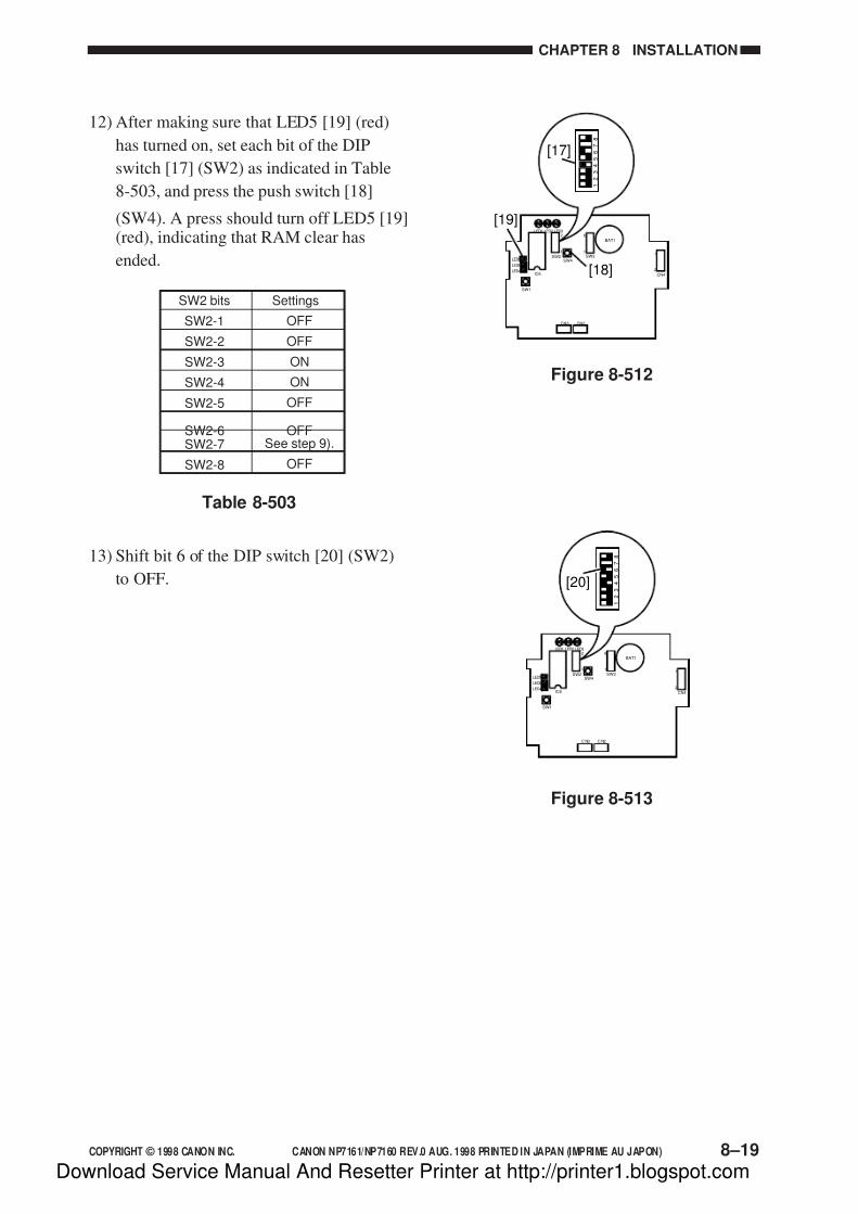
7/16/2019 Canon Np7161-Np7160 Copier Sm
http://slidepdf.com/reader/full/canon-np7161-np7160-copier-sm 211/345
COPYRIGHT © 1998 CANON INC. CANON NP7161/NP7160 REV.0 AUG. 1998 PRINTED IN JAPAN (IMPRIME AU JAPON) 8–19
CHAPTER 8 INSTALLATION
LED1 LED2 LED32
1
LED5
LED6
LED4IC6
SW1
SW4SW3
6
1
BAT1
CN4
1
2
CN3 CN2
1
2
3
4
5
6
7
8
SW2
[17]
[18]
[19]
Figure 8-512
LED1 LED2 LED32
1
LED5
LED6
LED4IC6
SW1
SW4SW3
6
1
BAT1
CN4
1
2
C N3 C N2
1
2
3
4
5
6
7
8
SW2
[20]
Figure 8-513
12) After making sure that LED5 [19] (red)
has turned on, set each bit of the DIP
switch [17] (SW2) as indicated in Table
8-503, and press the push switch [18]
(SW4). A press should turn off LED5 [19](red), indicating that RAM clear has
ended.
SW2 bits
SW2-1
SW2-2
SW2-3
SW2-4
SW2-5
SW2-6SW2-7
SW2-8
Settings
OFF
OFF
ON
ON
OFF
OFFSee step 9).
OFF
Table 8-503
13) Shift bit 6 of the DIP switch [20] (SW2)
to OFF.
Download Service Manual And Resetter Printer at http://printer1.blogspot.com
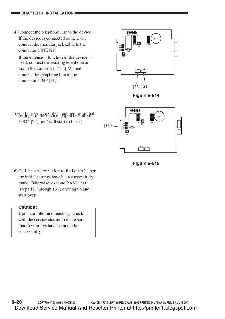
7/16/2019 Canon Np7161-Np7160 Copier Sm
http://slidepdf.com/reader/full/canon-np7161-np7160-copier-sm 212/345
CHAPTER 8 INSTALLATION
8–20 COPYRIGHT © 1998 CANON INC. CANON NP7161/NP7160 REV.0 AUG. 1998 PRINTED IN JAPAN (IMPRIME AU JAPON)
LED1 LED2 LED32
1
LED5
LED6
LED4IC6
SW1
SW4SW3
6
1
BAT1
CN4
1
2
CN3 CN2
SW2
[22] [21]
Figure 8-514
LED1 LED2 LED32
1
LED5
LED6
LED4IC6
SW1
SW4SW3
6
1
BAT1
CN4
1
2
CN3 CN2
SW2
[23]
Figure 8-515
14) Connect the telephone line to the device.
If the device is connected on its own,
connect the modular jack cable to the
connector LINE [21].
If the extension function of the device isused, connect the existing telephone or
fax to the connector TEL [22], and
connect the telephone line to the
connector LINE [21].
15) Call the service station, and request initialsettings for the device. (Upon reception,
LED4 [23] (red) will start to flash.)
16) Call the service station to find out whether
the initial settings have been successfully
made. Otherwise, execute RAM clear
(steps 11) through 13) ) once again and
start over.
Caution:
Upon completion of each try, check
with the service station to make sure
that the settings have been made
successfully.
Download Service Manual And Resetter Printer at http://printer1.blogspot.com

7/16/2019 Canon Np7161-Np7160 Copier Sm
http://slidepdf.com/reader/full/canon-np7161-np7160-copier-sm 213/345
COPYRIGHT © 1998 CANON INC. CANON NP7161/NP7160 REV.0 AUG. 1998 PRINTED IN JAPAN (IMPRIME AU JAPON) 8–21
CHAPTER 8 INSTALLATION
LED1 LED2 LED32
1
LED5
LED6
LED4IC6
SW1
SW4SW3
6
1
BAT1
CN4
1
2
CN 3 C N2
SW2
[18]
[24]
[25]
Figure 8-516
17) Check if the device is capable of ringing
up the computer at the service station.
Press the push switch [18] (SW4).
A press will turn on LED6 [24] (red): it
will turn off upon completion of transmission, and it will flash upon
failure.
Another press on the push switch (SW4)
[18] while LED6 [24] is flashing will
initiate transmission once again.
A press on the push switch (SW1) [25]
while LED 6 [24] is flashing will cancel
transmission attempts.
LED1 LED2 LED32
1
LED5
LED6
LED4IC6
SW1
SW4SW3
6
1
BAT1
CN4
1
2
C N3 CN 2
SW2
[27]
Figure 8-518
19) Press the copier’s Copy Start key so that
LED3 [27] (pink) flashes in response.
LED1 LED2 LED32
1
LED5
LED6
LED4IC6
SW1
SW4SW3
6
1
BAT1
CN4
1
2
C N3 C N2
SW2
[26]
Figure 8-517
18) Check to make sure that the
communication with the copier is normal.
Connect the copier’s power plug, and turn
on the power switch to see that LED2 [26]
(orange) flashes.
Download Service Manual And Resetter Printer at http://printer1.blogspot.com

7/16/2019 Canon Np7161-Np7160 Copier Sm
http://slidepdf.com/reader/full/canon-np7161-np7160-copier-sm 214/345
CHAPTER 8 INSTALLATION
8–22 COPYRIGHT © 1998 CANON INC. CANON NP7161/NP7160 REV.0 AUG. 1998 PRINTED IN JAPAN (IMPRIME AU JAPON)
20) Attach the switch settings label [28] on
the device, and record the settings of each
switch.
21) Secure the top cover [29] in place with
two screws [30]. At this time, check tomake sure that the cable is fixed in place
with the cable guide and is not trapped by
the top cover [29].
[28]
[30]
[29]
[30]
Figure 8-519
Download Service Manual And Resetter Printer at http://printer1.blogspot.com

7/16/2019 Canon Np7161-Np7160 Copier Sm
http://slidepdf.com/reader/full/canon-np7161-np7160-copier-sm 215/345
COPYRIGHT © 1998 CANON INC. CANON NP7161/NP7160 REV.0 AUG. 1998 PRINTED IN JAPAN (IMPRIME AU JAPON) 8–23
CHAPTER 8 INSTALLATION
[1]
[2]
Figure 8-601
Figure 8-602
[3] [4]
Figure 8-603
VI. INSTALLING THEACCESSORYCOUNTER
1) Open the front door; then, remove the
inside cover, and cut off the face plate [1].
2) Remove the delivery lower cover, and
mount the accessory counter [2] to the
counter assembly.
3) Connect the connector [3] of the
accessory counter to the connector [4] of
the counter assembly.
Download Service Manual And Resetter Printer at http://printer1.blogspot.com
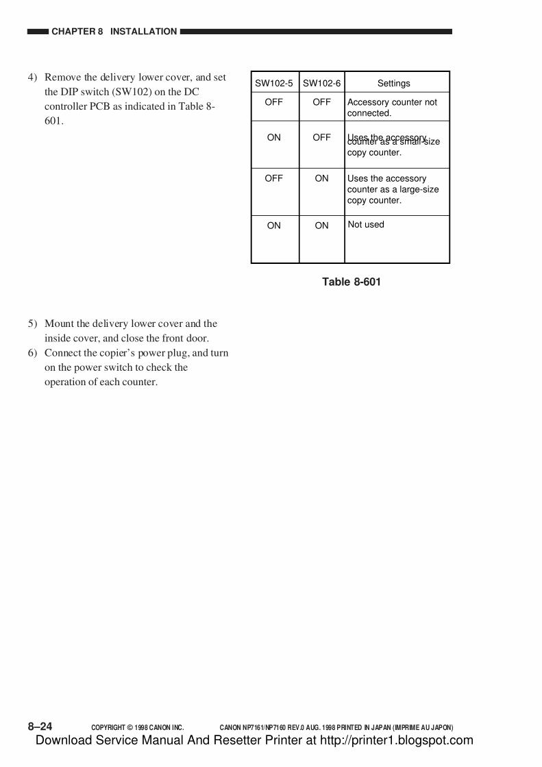
7/16/2019 Canon Np7161-Np7160 Copier Sm
http://slidepdf.com/reader/full/canon-np7161-np7160-copier-sm 216/345
CHAPTER 8 INSTALLATION
8–24 COPYRIGHT © 1998 CANON INC. CANON NP7161/NP7160 REV.0 AUG. 1998 PRINTED IN JAPAN (IMPRIME AU JAPON)
SW102-5
OFF
ON
OFF
ON
OFF Accessory counter notconnected.
Uses the accessorycounter as a small-sizecopy counter.
Uses the accessorycounter as a large-sizecopy counter.
Not used
OFF
ON
ON
SW102-6 Settings
Table 8-601
4) Remove the delivery lower cover, and set
the DIP switch (SW102) on the DC
controller PCB as indicated in Table 8-
601.
5) Mount the delivery lower cover and the
inside cover, and close the front door.
6) Connect the copier’s power plug, and turn
on the power switch to check the
operation of each counter.
Download Service Manual And Resetter Printer at http://printer1.blogspot.com

7/16/2019 Canon Np7161-Np7160 Copier Sm
http://slidepdf.com/reader/full/canon-np7161-np7160-copier-sm 217/345
COPYRIGHT © 1998 CANON INC. CANON NP7161/NP7160 REV.0 AUG. 1998 PRINTED IN JAPAN (IMPRIME AU JAPON) 8–25
CHAPTER 8 INSTALLATION
Figure 8-701
VII.INSTALLING THEACCESSORY HEATER
A. Installing the Heater Switch1) Remove the rear cover, and cut off the
face plate [1].
[1]
Figure 8-702
[2][3]
2) Mount the heater switch [2] with two
screws [3].
3) Lead the heater switch harness through
the clamp, and connect it to the connector
[4].
[4]
Figure 8-703
Download Service Manual And Resetter Printer at http://printer1.blogspot.com
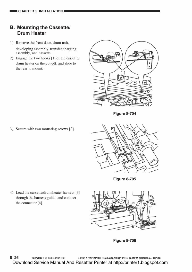
7/16/2019 Canon Np7161-Np7160 Copier Sm
http://slidepdf.com/reader/full/canon-np7161-np7160-copier-sm 218/345
CHAPTER 8 INSTALLATION
8–26 COPYRIGHT © 1998 CANON INC. CANON NP7161/NP7160 REV.0 AUG. 1998 PRINTED IN JAPAN (IMPRIME AU JAPON)
B. Mounting the Cassette/Drum Heater
1) Remove the front door, drum unit,
developing assembly, transfer chargingassembly, and cassette.
2) Engage the two hooks [1] of the cassette/
drum heater on the cut-off, and slide to
the rear to mount.[ 1 ]
Figure 8-704
Figure 8-705
[2]3) Secure with two mounting screws [2].
4) Lead the cassette/drum heater harness [3]
through the harness guide, and connect
the connector [4].
Figure 8-706
[3]
[4]
Download Service Manual And Resetter Printer at http://printer1.blogspot.com
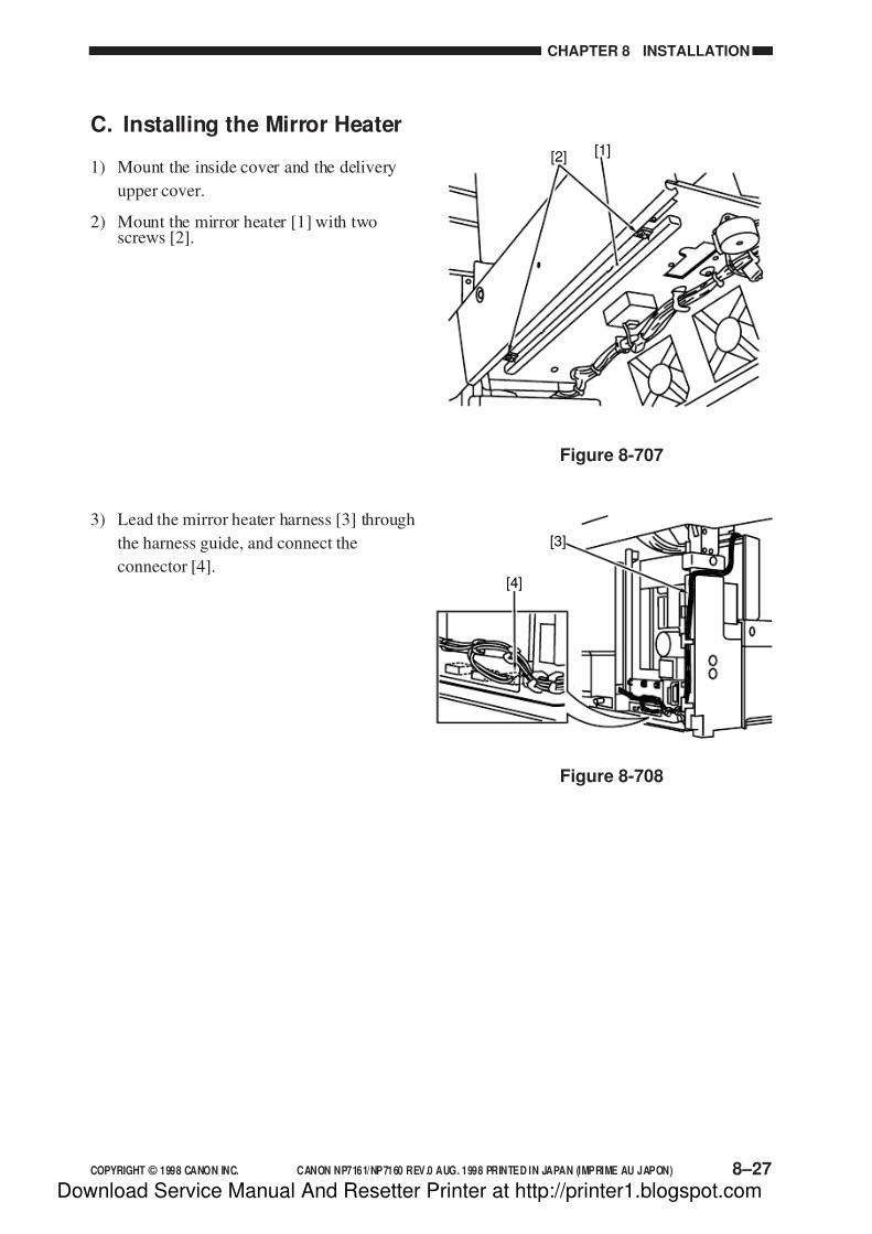
7/16/2019 Canon Np7161-Np7160 Copier Sm
http://slidepdf.com/reader/full/canon-np7161-np7160-copier-sm 219/345
COPYRIGHT © 1998 CANON INC. CANON NP7161/NP7160 REV.0 AUG. 1998 PRINTED IN JAPAN (IMPRIME AU JAPON) 8–27
CHAPTER 8 INSTALLATION
[2] [1]
C. Installing the Mirror Heater
1) Mount the inside cover and the delivery
upper cover.
2) Mount the mirror heater [1] with twoscrews [2].
3) Lead the mirror heater harness [3] through
the harness guide, and connect the
connector [4].[4]
[3]
Figure 8-707
Figure 8-708
Download Service Manual And Resetter Printer at http://printer1.blogspot.com

7/16/2019 Canon Np7161-Np7160 Copier Sm
http://slidepdf.com/reader/full/canon-np7161-np7160-copier-sm 220/345
Download Service Manual And Resetter Printer at http://printer1.blogspot.com
7/16/2019 Canon Np7161-Np7160 Copier Sm
http://slidepdf.com/reader/full/canon-np7161-np7160-copier-sm 221/345
COPYRIGHT © 1998 CANON INC. CANON NP7161/NP7160 REV.0 AUG. 1998 PRINTED IN JAPAN (IMPRIME AU JAPON)
CHAPTER 9
MAINTENANCE AND SERVICING
I. PERIODICALLY REPLACED PARTS ..... 9-1
A. Copier ................................................. 9-1II. CONSUMABLES AND DURABLES ........ 9-2
A. Copier ................................................. 9-2
III. SCHEDULED SERVICING CHART ........ 9-3
IV. SCHEDULED SERVICING TABLE ......... 9-5A. Copier ................................................. 9-5
This chapter provides tables of periodically replaced parts and consumables/durables and scheduled
servicing charts.
Download Service Manual And Resetter Printer at http://printer1.blogspot.com

7/16/2019 Canon Np7161-Np7160 Copier Sm
http://slidepdf.com/reader/full/canon-np7161-np7160-copier-sm 222/345
Download Service Manual And Resetter Printer at http://printer1.blogspot.com

7/16/2019 Canon Np7161-Np7160 Copier Sm
http://slidepdf.com/reader/full/canon-np7161-np7160-copier-sm 223/345
COPYRIGHT © 1998 CANON INC. CANON NP7161/NP7160 REV.0 AUG. 1998 PRINTED IN JAPAN (IMPRIME AU JAPON) 9–1
CHAPTER 9 MAINTENANCE AND SERVICING
I. PERIODICALLY REPLACED PARTS
Some of the parts of the copier need to be replaced on a periodical basis to ensure a specific
level of performance (regardless of external appearance or presence/absence of damage).
Plan replacement so that it coincides with a scheduled servicing visit.
A. CopierAs of August 1998
RemarksNo.
1
2
Parts name
Transfer charging wire
Ozone filter (exhaust)
Parts No.
FY3-0040-000
FE5-3956-000
Q’ty
AR
1
Expected life (copies)
60,000
60,000
Note:
The above values are estimates only, and are subject to change based on future data.
Or, 1 yr.
Download Service Manual And Resetter Printer at http://printer1.blogspot.com

7/16/2019 Canon Np7161-Np7160 Copier Sm
http://slidepdf.com/reader/full/canon-np7161-np7160-copier-sm 224/345
CHAPTER 9 MAINTENANCE AND SERVICING
9–2 COPYRIGHT © 1998 CANON INC. CANON NP7161/NP7160 REV.0 AUG. 1998 PRINTED IN JAPAN (IMPRIME AU JAPON)
II. CONSUMABLES AND DURABLES
Some of the parts of the copier may need to be replaced once or more because of wear or
damage over the period of machine warranty. Replace them when they fail.
A. Copier
Parts name
Scanning lamp
Pick-up roller
Feed rollerSeparation roller
Multifeeder pick-up roller
Multifeeder separation pad
Static eliminator
Developing cylinder
Fixing upper roller
Fixing lower roller
Fixing upper separation claw
Fixing lower separation claw
Heat discharge roller
Delivery roller
120,000
120,000
120,000
120,000120,000
120,000
120,000
60,000
180,000
180,000
180,000
180,000
180,000
120,000
120,000
FH7-3360-000
FH7-3361-000
FE5-4199-000
RF5-2490-000RF5-2490-000
FB1-8581-000
FE5-4132-000
FL5-0581-000
FM5-0721-000
FE5-3912-000
FE5-3905-000
FB1-7075-000
FA2-9037-000
FE5-3932-000
FE5-3927-000
120V
230V
1
1
2
11
1
1
1
1
1
1
5
4
1
1
RemarksNo. Parts No. Q’ty Expected life (copies)
As of August 1998
Come withthe packingof drum unit
1
2
34
5
6
7
8
9
10
11
12
13
14
Note:
The above values are estimates only, and are subject to change based on future data.
Download Service Manual And Resetter Printer at http://printer1.blogspot.com

7/16/2019 Canon Np7161-Np7160 Copier Sm
http://slidepdf.com/reader/full/canon-np7161-np7160-copier-sm 225/345
COPYRIGHT © 1998 CANON INC. CANON NP7161/NP7160 REV.0 AUG. 1998 PRINTED IN JAPAN (IMPRIME AU JAPON) 9–3
CHAPTER 9 MAINTENANCE AND SERVICING
III. SCHEDULED SERVICING CHART
Note:
1. As a rule, provide scheduled servicing every 60,000 copies.
2. Before setting out for a visit, check the Servicing Book, and take parts for which
replacement is expected.
Report to the person in charge.
Record the counter reading.
Make test copies (in Direct, Reduce,Enlarge).
Clean the optical assembly:• canning reflecting plate
• lens
• No. 1/2/3/4/5/6 mirror
• dust-proofing glass
Check the waste toner case.
Replace the transfer charging wire,
clean the transfer charging guide, and
clean the transfer guide:
• transfer guide (upper/lower) plate
• transfer/separation charging
assembly guide rail
Clean the separation/feeding assembly:
• separation static eliminator
• feeding assembly
Clean the fixing/delivery assembly:
• fixing (upper/lower) roller
• separation claw (upper/lower)
Provide scheduled servicing according
to the number of copies made.
Check the general condition.
Check the faulty copies.
a. density of imagesb.soiling of the background
c. clarity of characters
d.margin along the leading
edge
e. margin on the left/right
f. fixing, registration
(displacement), soling of
backs
g.abnormal noise
h.counter operation
Collect the waste toner case is full.
Use a blower brush; if dirt isexcessive, use alcohol.
Dry wipe with lint-free paper ;
if necessary use alcohol.
Lubricant
Step Work Checks Remarks
1
2
3
4
5
6
7
8
9
Download Service Manual And Resetter Printer at http://printer1.blogspot.com

7/16/2019 Canon Np7161-Np7160 Copier Sm
http://slidepdf.com/reader/full/canon-np7161-np7160-copier-sm 226/345
CHAPTER 9 MAINTENANCE AND SERVICING
9–4 COPYRIGHT © 1998 CANON INC. CANON NP7161/NP7160 REV.0 AUG. 1998 PRINTED IN JAPAN (IMPRIME AU JAPON)
10
11
12
13
14
15
Clean the copyboard cover and the
copyboard glass.
Make test copies.
Make sample copies.
Put the sample copies in order, and
clean up the area around the machine.
Record the latest counter reading.
Fill out the Service Sheet, and report to
the person in charge.
Step Work Checks Remarks
Use alcohol.
Download Service Manual And Resetter Printer at http://printer1.blogspot.com
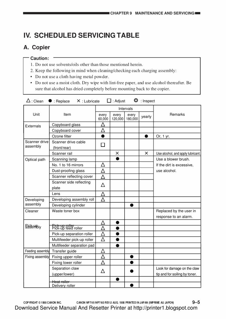
7/16/2019 Canon Np7161-Np7160 Copier Sm
http://slidepdf.com/reader/full/canon-np7161-np7160-copier-sm 227/345
COPYRIGHT © 1998 CANON INC. CANON NP7161/NP7160 REV.0 AUG. 1998 PRINTED IN JAPAN (IMPRIME AU JAPON) 9–5
CHAPTER 9 MAINTENANCE AND SERVICING
IV. SCHEDULED SERVICING TABLE
A. Copier
Caution:
1. Do not use solvents/oils other than those mentioned herein.
2. Keep the following in mind when cleaning/checking each charging assembly:
• Do not use a cloth having metal powder.
• Do not use a moist cloth. Dry wipe with lint-free paper, and use alcohol thereafter. Be
sure that alcohol has dried completely before mounting back to the copier.
Unit
Externals Copyboard glass
Copyboard cover
Ozone filter
Scanner drive cable
(front/rear)
Scanner rail
Scanning lamp
No. 1 to 16 mirrors
Dust-proofing glass
Scanner reflecting cover
Scanner side reflecting
plate
Lens
Developing assembly roll
Developing cylinder
Waste toner box
Pick-up rollerPick-up feed roller
Pick-up separation roller
Multifeeder pick-up roller
Multifeeder separation pad
Transfer guide
Fixing upper roller
Fixing lower roller
Separation claw
(upper/lower)
Heat rollerDelivery roller
Or, 1 yr.
Use alcohol, and apply lubricant.
Use a blower brush.
If the dirt is excessive,
use alcohol.
Replaced by the user in
response to an alarm.
Look for damage on the claw
tip and for soiling by toner.
Item Remarksevery60,000
every120,000
every180,000
yearly
Intervals
Scanner driveassembly
Optical path
Developingassembly
Cleaner
Pick-upassembly
Feeding assembly
Fixing assembly
: Clean : Replace : Lubricate : Adjust : Inspect
Download Service Manual And Resetter Printer at http://printer1.blogspot.com
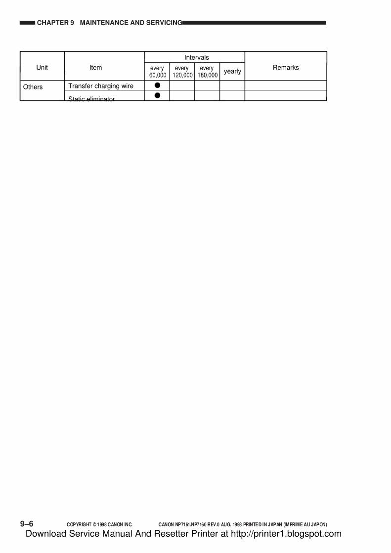
7/16/2019 Canon Np7161-Np7160 Copier Sm
http://slidepdf.com/reader/full/canon-np7161-np7160-copier-sm 228/345
CHAPTER 9 MAINTENANCE AND SERVICING
9–6 COPYRIGHT © 1998 CANON INC. CANON NP7161/NP7160 REV.0 AUG. 1998 PRINTED IN JAPAN (IMPRIME AU JAPON)
Others Transfer charging wire
Static eliminator
Unit Item Remarksevery60,000
every120,000
every180,000
yearly
Intervals
Download Service Manual And Resetter Printer at http://printer1.blogspot.com

7/16/2019 Canon Np7161-Np7160 Copier Sm
http://slidepdf.com/reader/full/canon-np7161-np7160-copier-sm 229/345
COPYRIGHT © 1998 CANON INC. CANON NP7161/NP7160 REV.0 AUG. 1998 PRINTED IN JAPAN (IMPRIME AU JAPON)
CHAPTER 10
TROUBLESHOOTING
This chapter provides tables of maintenance/inspection, standards/adjustments, and identification of
problems (image fault/malfunction).
A. Sensors and Switches ................... 10-70
B. Motors, Fans, Clutches,and Solenoids................................. 10-72
C. Heaters, Lamps, and Others .......... 10-74
D. PCBs .............................................. 10-76E. Variable Resistors, Light-Emitting
Diodes, and Check Pins by PCB ... 10-77
VII. SERVICE MODE .................................. 10-82A. Outline ............................................ 10-82
B. Using Service Mode ....................... 10-82C. Using Adjust Mode and
Function Mode................................ 10-83
D. Display Mode [1] ............................ 10-84
E. I/O Display Mode [2]....................... 10-88F. Adjust Mode [3] .............................. 10-92
G. Function Mode [4] .......................... 10-94H. Option Mode [5] .............................. 10-95
I. Counter Mode [6] ........................... 10-97
J. Application Mode [7]....................... 10-98
VIII. SELF DIAGNOSIS .............................. 10-99A. Copier ............................................. 10-99
B. ADF .............................................. 10-103C. Sorter ............................................ 10-104
D. Cassette Feeding Module ............ 10-104
I. GUIDE TO TROUBLESHOOTING
TABLES .................................................. 10-1A. Image Adjustment Basic Procedure 10-3
B. Points to Note for Scheduled Servicing . 10-4
II. STANDARDS AND ADJUSTMENTS .... 10-5
A. Mechanical ....................................... 10-5B. Exposure System ............................. 10-7
C. Image Formation System ............... 10-10
D. Pick-Up/Feeding System ............... 10-14
E. Fixing System ................................. 10-16F. Electrical System ............................ 10-18
III. IMAGE FAULTS ................................... 10-25
A. Initial Checks .................................. 10-25B. Image Fault Samples ..................... 10-28
C. Troubleshooting Image Faults ....... 10-29
IV. TROUBLESHOOTING
MALFUNCTIONS ................................. 10-42A. Copier ............................................. 10-42
V. TROUBLESHOOTING FEEDING
PROBLEMS.......................................... 10-66A. Copy Jams ..................................... 10-66
B. Faulty Feeding................................ 10-69VI. ARRANGEMENT AND FUNCTIONS
OF ELECTRICAL PARTS .................... 10-70
Download Service Manual And Resetter Printer at http://printer1.blogspot.com

7/16/2019 Canon Np7161-Np7160 Copier Sm
http://slidepdf.com/reader/full/canon-np7161-np7160-copier-sm 230/345
Download Service Manual And Resetter Printer at http://printer1.blogspot.com

7/16/2019 Canon Np7161-Np7160 Copier Sm
http://slidepdf.com/reader/full/canon-np7161-np7160-copier-sm 231/345
COPYRIGHT © 1998 CANON INC. CANON NP7161/NP7160 REV.0 AUG. 1998 PRINTED IN JAPAN (IMPRIME AU JAPON)
CHAPTER 10 TROUBLESHOOTING
10–1
I. GUIDE TO TROUBLESHOOTING TABLES
The troubleshooting tables in this chapter are based on more commonly used troubleshooting
flow charts.
Study the following for an idea of how you may take advantage of the tables.
EX: AC power is absent.
s If you want to find out the possible causes (faulty parts) associated with a specific problem,
see the items under “Cause.”
In the case of the above, i.e., “AC power is absent,” you may suspect the power plug,
doors and covers, or power source.
s If you want to find out the checks to make or the actions to take for a specific problem,
follow the instructions under “Checks” and “Actions” in sequence. Answer the question
Yes or No, and if your answer matches the answer given under “Yes/No,” take the actiongiven under “Actions”; otherwise, go to the next step and work likewise.
Rest omitted.
Cause
Power plug
Step
1
2
3
4
NO
NO
NO
YES
Checks Yes/No Actions
Covers
Power source
Is the power plug connected to
the power outlet?
Are the front door and delivery
cover closed properly?
Is the rated voltage present at the
power outlet?
Is the rated voltage present between
J1-1 and J1-2? (J1 is found near
the power cord mount.)
Connect the power
plug.
Close the door and
the cover properly.
This is not the copier's
problem. Inform the
user accordingly.
Go to step 6.
Download Service Manual And Resetter Printer at http://printer1.blogspot.com

7/16/2019 Canon Np7161-Np7160 Copier Sm
http://slidepdf.com/reader/full/canon-np7161-np7160-copier-sm 232/345
CHAPTER 10 TROUBLESHOOTING
COPYRIGHT © 1998 CANON INC. CANON NP7161/NP7160 REV.0 AUG. 1998 PRINTED IN JAPAN (IMPRIME AU JAPON)10–2
YES
NO
Yes/No Actions
Connect the power plug.
Is thepower plug connected
to the power outlet?
Checks
Rest omitted
Step
1
YES
NOClose the door properly.
Is the frontdoor closed properly?2
YES
NO This is not the copier’sproblem. Inform the useraccordingly.
Is the ratedvoltage present
at the power outlet?3
s The instruction “Measure the voltage between J109-1 (+) and J109-2 (-) on the DC
controller PCB” means you are expected to make the following connections:
Connect the positive probe of your meter to J109-1 (+), and
Connect the negative probe of your meter to J109-2 (-).
Download Service Manual And Resetter Printer at http://printer1.blogspot.com
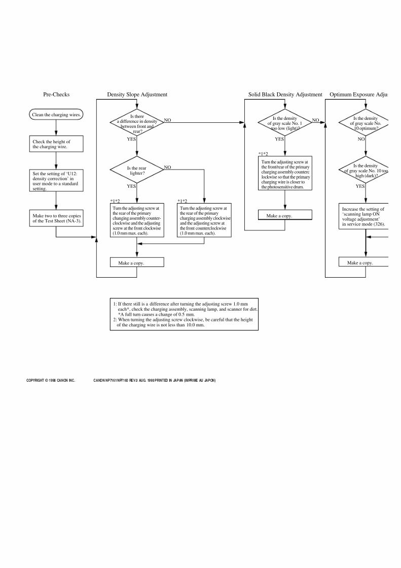
7/16/2019 Canon Np7161-Np7160 Copier Sm
http://slidepdf.com/reader/full/canon-np7161-np7160-copier-sm 233/345
COPYRIGHT © 1998 CANON INC. CANON NP7161/NP7160 REV.0 AUG. 1998 PRINTED IN JAPAN (IMPRIME AU JAPON)
Pre-Checks Density Slope Adjustment Solid Black Density Adjustment Optimum Exposure Adjus
Clean the charging wires. Is therea difference in density
between front andrear?
Make two to three copiesof the Test Sheet (NA-3).
Make a copy.
Check the height of the charging wire.
Set the setting of ‘U12:density correction’ inuser mode to a standardsetting.
Turn the adjusting screw atthe rear of the primarychanging assembly counter-clockwise and the adjustingscrew at the front clockwise(1.0 mm max. each).
Turn the adjusting screw atthe rear of the primarycharging assembly clockwiseand the adjusting screw atthe front counterclockwise(1.0 mm max. each).
Make a copy.
Turn the adjusting screw atthe front/rear of the primarycharging assembly counterclockwise so that the primarycharging wire is closer tothe photosensitive drum.
Increase the setting of ‘scanning lamp ONvoltage adjustment’in service mode (326).
Is the rearlighter?
YES
YES
NO
NO Is the densityof gray scale No. 1
too low (light)?
YES
NO
Make a copy.
Is the densityof gray scale No.
10 optimum?
NO
Is the densityof gray scale No. 10 too
high (dark)?
YES
*1*2 *1*2
*1*2
1: If there still is a difference after turning the adjusting screw 1.0 mmeach*, check the charging assembly, scanning lamp, and scanner for dirt.*A full turn causes a change of 0.5 mm.
2: When turning the adjusting screw clockwise, be careful that the heightof the charging wire is not less than 10.0 mm.

7/16/2019 Canon Np7161-Np7160 Copier Sm
http://slidepdf.com/reader/full/canon-np7161-np7160-copier-sm 234/345
COPYRIGHT © 1998 CANON INC.10–4
B. Points to Note for Scheduled Servicing
Part
Lens Blower brush Cleaning
Copyboard glass Alcohol Cleaning
Scanner rail Lubricant Lubricate
Reflecting plate Blower brush Cleaning
No. 1 to 3 mirrors Blower brush; or,alcohol and lint-free
paper
Cleaning with a blowerbrush; if excessive,
cleaning with alcohol
Tool/solvent Remarks Part
Part
Part
Part Tool/solvent Remarks
Charging wire
Static elimina
Developing ro
Dust-proofing
No. 4 to 6 mir
Fixing upper roller,Fixing lower roller
Dry wiping
Cleaning
Lint-free paper
Lubricant andlint-free paper
Separation claw(upper/lower)
Separation ro
Feed roller
Pick-up roller
Multifeeder pick
Transfer guide
Waste toner b
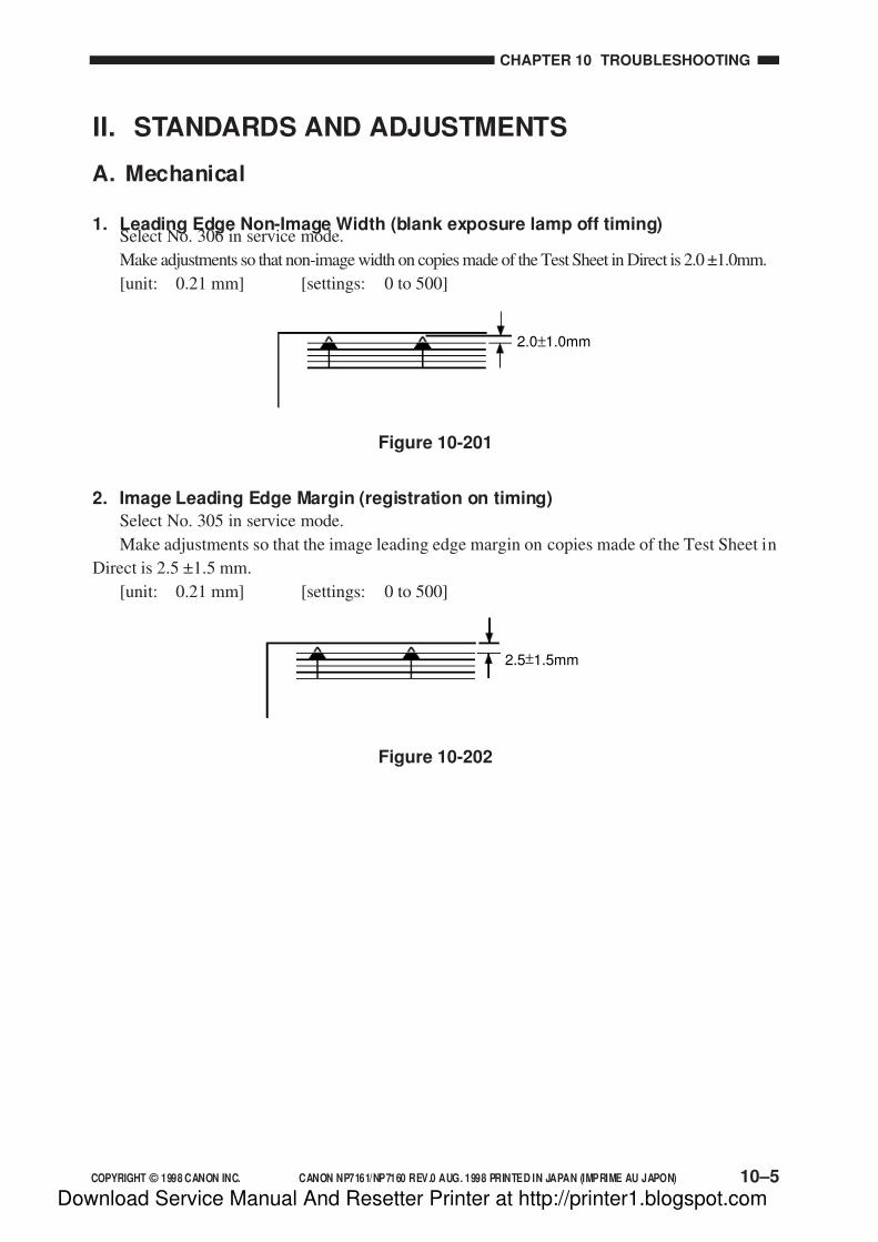
7/16/2019 Canon Np7161-Np7160 Copier Sm
http://slidepdf.com/reader/full/canon-np7161-np7160-copier-sm 235/345
COPYRIGHT © 1998 CANON INC. CANON NP7161/NP7160 REV.0 AUG. 1998 PRINTED IN JAPAN (IMPRIME AU JAPON)
CHAPTER 10 TROUBLESHOOTING
10–5
II. STANDARDS AND ADJUSTMENTS
A. Mechanical
1. Leading Edge Non-Image Width (blank exposure lamp off timing)Select No. 306 in service mode.
Make adjustments so that non-image width on copies made of the Test Sheet in Direct is 2.0 ±1.0mm.
[unit: 0.21 mm] [settings: 0 to 500]
2. Image Leading Edge Margin (registration on timing)
Select No. 305 in service mode.
Make adjustments so that the image leading edge margin on copies made of the Test Sheet in
Direct is 2.5 ±1.5 mm.
[unit: 0.21 mm] [settings: 0 to 500]
2.0±1.0mm
2.5±1.5mm
Figure 10-201
Figure 10-202
Download Service Manual And Resetter Printer at http://printer1.blogspot.com

7/16/2019 Canon Np7161-Np7160 Copier Sm
http://slidepdf.com/reader/full/canon-np7161-np7160-copier-sm 236/345
CHAPTER 10 TROUBLESHOOTING
COPYRIGHT © 1998 CANON INC. CANON NP7161/NP7160 REV.0 AUG. 1998 PRINTED IN JAPAN (IMPRIME AU JAPON)10–6
[3]
[1]
[2]
Figure 10-203
024
6
8
10
(-) (+)
Figure 10-204
3. Left/Right Registration (cassette)
Make adjustments by moving the horizontal registration adjusting screw of the cassette so
that the distance between the copy image and the copy paper is 0 ±2.0 mm on copies made of the
Test Sheet in Direct.
Turn the adjusting screw [1] until the cassette locking lever plate [2] and the cassette lockinglever [3] engage.
When the adjusting screw [1] is turned clockwise, the cassette locking plate moves to the
front.
When the adjusting screw [1] is turned counterclockwise, the cassette locking lever plate [2]
moves to the rear.
Download Service Manual And Resetter Printer at http://printer1.blogspot.com

7/16/2019 Canon Np7161-Np7160 Copier Sm
http://slidepdf.com/reader/full/canon-np7161-np7160-copier-sm 237/345
COPYRIGHT © 1998 CANON INC. CANON NP7161/NP7160 REV.0 AUG. 1998 PRINTED IN JAPAN (IMPRIME AU JAPON)
CHAPTER 10 TROUBLESHOOTING
10–7
B. Exposure System
1. Routing the Scanner Drive Cable
Route the cable following steps [1] through [7], and perform the steps under “Adjusting the
Tension of the Cable” and “Adjusting the Position of the Mirror.”
Figure 10-205
[4][3]
[2]
[6]
[2]
[6]
[1]
Secure temporarily.
Steel ball
Wind 11 times.
[5]
[7]
Download Service Manual And Resetter Printer at http://printer1.blogspot.com
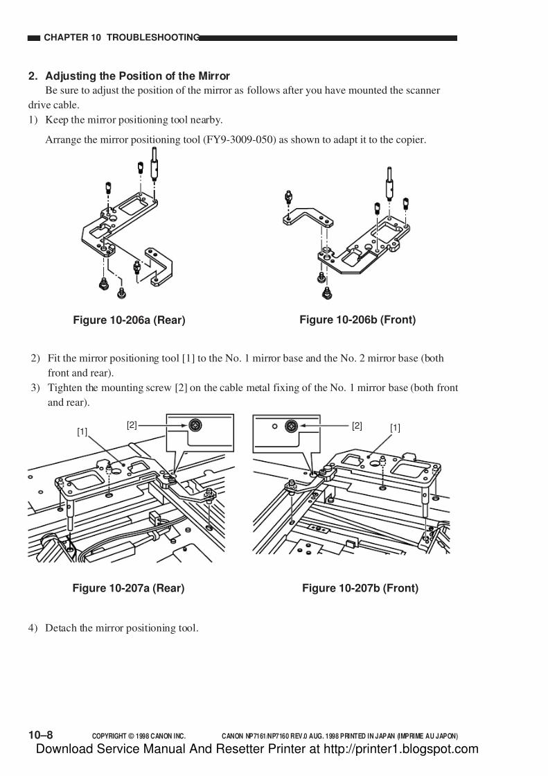
7/16/2019 Canon Np7161-Np7160 Copier Sm
http://slidepdf.com/reader/full/canon-np7161-np7160-copier-sm 238/345
CHAPTER 10 TROUBLESHOOTING
COPYRIGHT © 1998 CANON INC. CANON NP7161/NP7160 REV.0 AUG. 1998 PRINTED IN JAPAN (IMPRIME AU JAPON)10–8
2. Adjusting the Position of the Mirror
Be sure to adjust the position of the mirror as follows after you have mounted the scanner
drive cable.
1) Keep the mirror positioning tool nearby.
Arrange the mirror positioning tool (FY9-3009-050) as shown to adapt it to the copier.
Figure 10-206b (Front)Figure 10-206a (Rear)
2) Fit the mirror positioning tool [1] to the No. 1 mirror base and the No. 2 mirror base (both
front and rear).
3) Tighten the mounting screw [2] on the cable metal fixing of the No. 1 mirror base (both front
and rear).
[1][2] [1][2]
Figure 10-207a (Rear) Figure 10-207b (Front)
4) Detach the mirror positioning tool.
Download Service Manual And Resetter Printer at http://printer1.blogspot.com

7/16/2019 Canon Np7161-Np7160 Copier Sm
http://slidepdf.com/reader/full/canon-np7161-np7160-copier-sm 239/345
COPYRIGHT © 1998 CANON INC. CANON NP7161/NP7160 REV.0 AUG. 1998 PRINTED IN JAPAN (IMPRIME AU JAPON)
CHAPTER 10 TROUBLESHOOTING
10–9
3. Adjusting the Tension of the Scanner Drive Cable
Be sure to adjust the tension as follows after routing the scanner drive cable.
1) Move the scanner to home position.
2) Pull the center of the scanner drive cable with a spring gauge about 10 mm. At this time,
adjust the position [A] of the tension spring [1] so that the reading of the spring gauge is 95 ±15 g.
[1][1][A]
Figure 10-209
10mm
10mm
S c a n n e r
Figure 10-208
Download Service Manual And Resetter Printer at http://printer1.blogspot.com

7/16/2019 Canon Np7161-Np7160 Copier Sm
http://slidepdf.com/reader/full/canon-np7161-np7160-copier-sm 240/345
CHAPTER 10 TROUBLESHOOTING
COPYRIGHT © 1998 CANON INC. CANON NP7161/NP7160 REV.0 AUG. 1998 PRINTED IN JAPAN (IMPRIME AU JAPON)10–10
C. Image Formation System
1. Outline
As many as two charging wires are located around the photosensitive drum. (These charging
wires are 0.06 mm in diameter.)
2. Stringing the Charging Wires
Basically, all charging wires are strung in the same way. (The following uses the primary
charging wire as an example.)
1) Remove the mounting screw [1], and remove the stopper [2] and the grid plate [3].
To remove the transfer charging assembly, remove the three hooks [a], and remove the guide
wire plate [b].
• Transfer Charging Assembly
Figure 10-210b
• Primary Charging Assembly
Figure 10-210a
[1]
[2][3]
2) Remove the sheet (front) [4] and the sheet (rear) [5].
To remove the transfer charging assembly, remove the sheet (front) [c] and the sheet (rear) [d].
• Transfer Charging Assembly
Figure 10-211b
• Primary Charging Assembly
Figure 10-211a
[4][5]
[c] [d]
[a] [a][a]
[b]
Download Service Manual And Resetter Printer at http://printer1.blogspot.com

7/16/2019 Canon Np7161-Np7160 Copier Sm
http://slidepdf.com/reader/full/canon-np7161-np7160-copier-sm 241/345
COPYRIGHT © 1998 CANON INC. CANON NP7161/NP7160 REV.0 AUG. 1998 PRINTED IN JAPAN (IMPRIME AU JAPON)
CHAPTER 10 TROUBLESHOOTING
10–11
3) Remove the spring [6], and remove the charging wire [7].
To remove the transfer charging assembly, remove the spring [e], and remove the charging
wire [f].
• Primary Charging Assembly
Figure10-212a
• Transfer Charging Assembly
Figure 10-212b
[f][e]
4) Free a length of about 5 cm of charging wire (0.06-mm dia.) from the reel, and form a loop at
the end (2-mm dia.).
Note:
To form a loop easily, wind the charging wire around a hex key once; then, turn the hex
key three to four times, and twist the charging wire.
5) Cut the excess end of the twisted charging wire with a nipper.6) Hook the loop on the charging electrode at the rear.
Figure 10-213
7) Hook the charging wire on the charging wire positioner at the rear; then, pull on the charging
wire as indicated, and hook the charging wire tension spring on the charging wire by the
distance A ; then, twist it.
A:
• Primary charging assembly : 13.0 ± 0.5 mm
• Transfer charging assembly : 12.0 ± 0.5 mm
[6][7]
Download Service Manual And Resetter Printer at http://printer1.blogspot.com
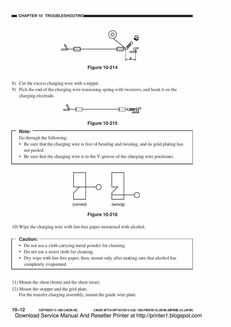
7/16/2019 Canon Np7161-Np7160 Copier Sm
http://slidepdf.com/reader/full/canon-np7161-np7160-copier-sm 242/345
CHAPTER 10 TROUBLESHOOTING
COPYRIGHT © 1998 CANON INC. CANON NP7161/NP7160 REV.0 AUG. 1998 PRINTED IN JAPAN (IMPRIME AU JAPON)10–12
Figure 10-215
11) Mount the sheet (front) and the sheet (rear).
12) Mount the stopper and the grid plate.
For the transfer charging assembly, mount the guide wire plate.
10) Wipe the charging wire with lint-free paper moistened with alcohol.
Caution:
• Do not use a cloth carrying metal powder for cleaning.
• Do not use a moist cloth for cleaning.
• Dry wipe with lint-free paper; then, mount only after making sure that alcohol has
completely evaporated.
8) Cut the excess charging wire with a nipper.
9) Pick the end of the charging wire tensioning spring with tweezers, and hook it on the
charging electrode.
Figure 10-216
A
Figure 10-214
Note:
Go through the following:
• Be sure that the charging wire is free of bending and twisting, and its gold plating has
not peeled.
• Be sure that the charging wire is in the V-groove of the charging wire positioner.
(correct) (wrong)
Download Service Manual And Resetter Printer at http://printer1.blogspot.com

7/16/2019 Canon Np7161-Np7160 Copier Sm
http://slidepdf.com/reader/full/canon-np7161-np7160-copier-sm 243/345
COPYRIGHT © 1998 CANON INC. CANON NP7161/NP7160 REV.0 AUG. 1998 PRINTED IN JAPAN (IMPRIME AU JAPON)
CHAPTER 10 TROUBLESHOOTING
10–13
• Transfer Charging Assembly• Primary Charging Assembly
Figure 10-217
Height adjustingscrew
Height adjustingscrew
Height adjustingscrew
Height adjustingscrew
Figure 10-218bFigure 10-218a
3. Adjusting the Height of the Charging Wires
To adjust each charging wire, turn its respective height adjusting screw. A full turn on the
screw will change the height of the primary charging wire by about 0.5 mm and that of the
transfer charging wire by about 0.7 mm.
Chargingassembly
Height of chargingwire (mm)
Range
Primary 1.0mm11.0 0.2mm
9.5 0.2mm
Transfer 1.0mm
Download Service Manual And Resetter Printer at http://printer1.blogspot.com

7/16/2019 Canon Np7161-Np7160 Copier Sm
http://slidepdf.com/reader/full/canon-np7161-np7160-copier-sm 244/345
CHAPTER 10 TROUBLESHOOTING
COPYRIGHT © 1998 CANON INC. CANON NP7161/NP7160 REV.0 AUG. 1998 PRINTED IN JAPAN (IMPRIME AU JAPON)10–14
Figure 10-219
Figure 10-220
•AB
•INCH
[1][2]
[1][2]
2. Changing the Cassette Size (AB/INCH)
1) Slide out the cassette.2) Loosen the mounting screw [1] on the left side of the cassette; then, slide the size switching
block [2] to the desired size position, and fix it in position.
[2]
[B]
[A]
[1]
D. Pick-Up/Feeding System
1. Adjusting the Pressure of the Separation Pad
If double feeding or pick-up failure occurs, loosen the adjusting screw [1] and relocate the
holder [2] to adjust the force of the separation pad tension spring.• If pick-up occurs, move the holder in the direction of [A].
• If double feeding failure occurs, move the holder to in the direction of [B].
Download Service Manual And Resetter Printer at http://printer1.blogspot.com

7/16/2019 Canon Np7161-Np7160 Copier Sm
http://slidepdf.com/reader/full/canon-np7161-np7160-copier-sm 245/345
COPYRIGHT © 1998 CANON INC. CANON NP7161/NP7160 REV.0 AUG. 1998 PRINTED IN JAPAN (IMPRIME AU JAPON)
CHAPTER 10 TROUBLESHOOTING
10–15
3) Remove the mounting screw [3]; then, slide the size switching lever [4] to the desired size
position, and fix it in place.
Figure 10-221
[3]
[4]
[3]
[4]
•AB
•INCH
Download Service Manual And Resetter Printer at http://printer1.blogspot.com
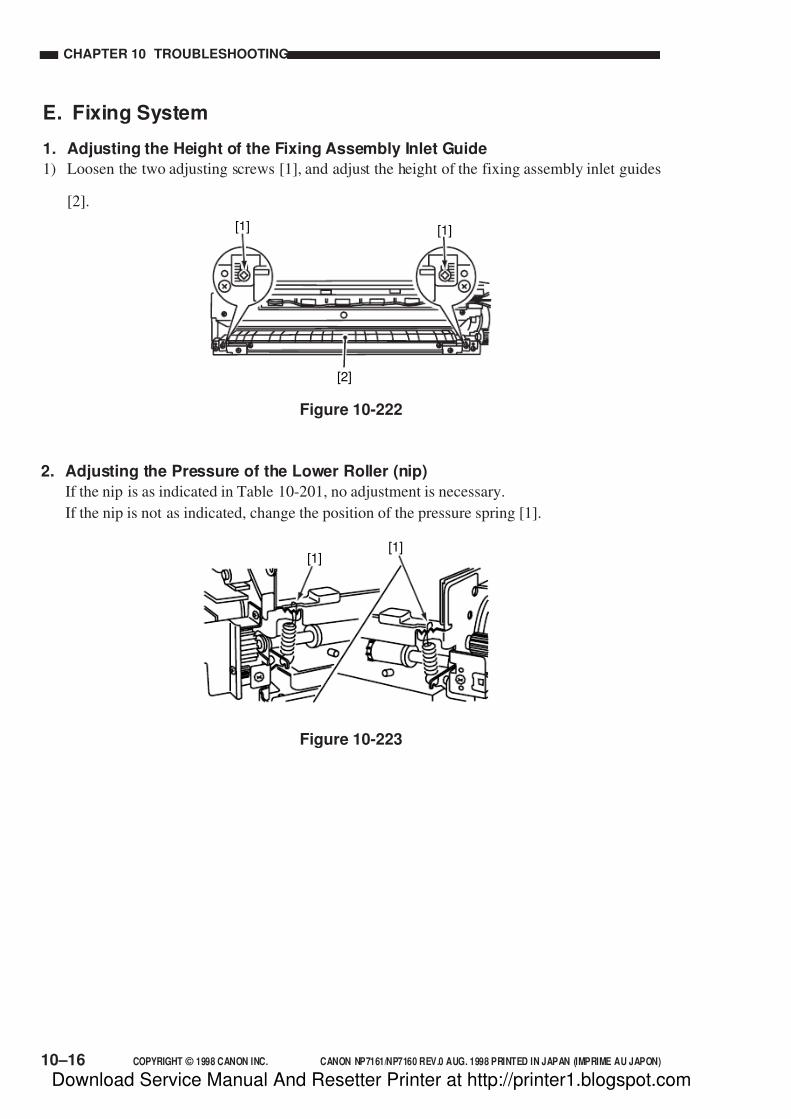
7/16/2019 Canon Np7161-Np7160 Copier Sm
http://slidepdf.com/reader/full/canon-np7161-np7160-copier-sm 246/345
CHAPTER 10 TROUBLESHOOTING
COPYRIGHT © 1998 CANON INC. CANON NP7161/NP7160 REV.0 AUG. 1998 PRINTED IN JAPAN (IMPRIME AU JAPON)10–16
E. Fixing System
1. Adjusting the Height of the Fixing Assembly Inlet Guide
1) Loosen the two adjusting screws [1], and adjust the height of the fixing assembly inlet guides
[2].
[1][1]
[2]
2. Adjusting the Pressure of the Lower Roller (nip)
If the nip is as indicated in Table 10-201, no adjustment is necessary.
If the nip is not as indicated, change the position of the pressure spring [1].
Figure 10-222
[1][1]
Figure 10-223
Download Service Manual And Resetter Printer at http://printer1.blogspot.com
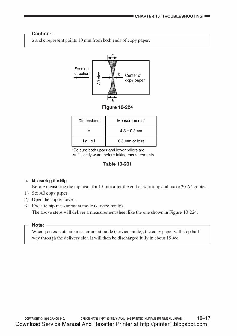
7/16/2019 Canon Np7161-Np7160 Copier Sm
http://slidepdf.com/reader/full/canon-np7161-np7160-copier-sm 247/345
COPYRIGHT © 1998 CANON INC. CANON NP7161/NP7160 REV.0 AUG. 1998 PRINTED IN JAPAN (IMPRIME AU JAPON)
CHAPTER 10 TROUBLESHOOTING
10–17
Caution:
a and c represent points 10 mm from both ends of copy paper.
Figure 10-224
Feedingdirection
a
c
A 3
s i z e
Center ofcopy paper
b
b
I a - c I
Dimensions
*Be sure both upper and lower rollers aresufficiently warm before taking measurements.
4.8 ± 0.3mm
0.5 mm or less
Measurements*
Table 10-201
a. Measuring the Nip
Before measuring the nip, wait for 15 min after the end of warm-up and make 20 A4 copies:
1) Set A3 copy paper.
2) Open the copier cover.
3) Execute nip measurement mode (service mode).
The above steps will deliver a measurement sheet like the one shown in Figure 10-224.
Note:
When you execute nip measurement mode (service mode), the copy paper will stop half
way through the delivery slot. It will then be discharged fully in about 15 sec.
Download Service Manual And Resetter Printer at http://printer1.blogspot.com

7/16/2019 Canon Np7161-Np7160 Copier Sm
http://slidepdf.com/reader/full/canon-np7161-np7160-copier-sm 248/345
CHAPTER 10 TROUBLESHOOTING
COPYRIGHT © 1998 CANON INC. CANON NP7161/NP7160 REV.0 AUG. 1998 PRINTED IN JAPAN (IMPRIME AU JAPON)10–18
F. Electrical System
1. Obtaining Optimum Exposure
You can adjust the intensity of the scanning lamp (LA1) at F5 as follows (effective for both
AE and manual):1) Set the setting of ‘U12’ (density correction) in user mode to its initial value.
2) Place the Test Sheet (NA-3) on the copyboard, and select non-AE and Direct.
3) Select ‘216’ (density adjusting volume voltage display) in service mode.
4) Slide the density adjusting volume until the copy count indicator indicates ‘245’ as the F5
voltage.
5) Make a copy.
6) Check the copy image, and change the setting of ‘326’ (scanning lamp on voltage
adjustment) in service mode using the keypad.
[1] A higher setting will increase the intensity, making the image lighter.
[2] A lower setting will decrease the intensity, making the image darker.
[1]
[2]
1 5 9Copydensity
Intensity (manual)
[1]
[2]
Test ChartOriginaldensity
Intensity (AE)
Copydensity
Figure 10-225
7) Press the Start key, and store the setting.
• Repeat steps 5) through 7) until an optimum image is obtained.
8) Press the Reset key to end service mode.
Download Service Manual And Resetter Printer at http://printer1.blogspot.com

7/16/2019 Canon Np7161-Np7160 Copier Sm
http://slidepdf.com/reader/full/canon-np7161-np7160-copier-sm 249/345
COPYRIGHT © 1998 CANON INC. CANON NP7161/NP7160 REV.0 AUG. 1998 PRINTED IN JAPAN (IMPRIME AU JAPON)
CHAPTER 10 TROUBLESHOOTING
10–19
2. AE Adjustment
If copies of a newspaper are foggy or if you have replaced the scanning lamp (LA1), AE
sensor, or DC controller PCB, perform the following:
(Be sure that the image is an optimum image before starting the work.)
a. AE Auto Adjustment
1. AE Scanning Intensity Auto Adjustment
1) Select ‘301’ (AE auto adjustment) in service mode.
2) Place the Test Chart (white background original) on the copyboard glass.
3) Press ‘0’ of the keypad so that the copy count indicator indicates ‘0’.
4) Press the Start key.
• The scanner moves to the AE scan position, stops, and performs AE exposure. Then, the
scanner moves in reverse to home position. (15 sec from start of forward movement and
the end of reverse movement)
• The output of the AE sensor will be indicated in the copy count indicator. Check to make
sure it is 80 ±5. If not, execute ‘302’ (AE scanning intensity adjustment) in service mode.
2. AE Slope Auto Adjustment
5) Select ‘301’ (AE auto adjustment) in service mode.
6) Place a newspaper on the copyboard glass.
7) Press ‘1’ of the keyboard so that the copy count indicator indicates ‘1’.
8) Press the Start key.
• The scanner moves to the AE scan position, stops, and performs AE exposure. Then, the
scanner moves in reverse to home position. (15 sec from start of forward movement andthe end of reverse movement)
• The output of the AE sensor will be indicated in the copy count indicator. Check to make
sure it is between 0 and 255. If not, execute ‘303’ (AE slope adjustment) in service mode.
9) Press the Reset key to end service mode.
Download Service Manual And Resetter Printer at http://printer1.blogspot.com

7/16/2019 Canon Np7161-Np7160 Copier Sm
http://slidepdf.com/reader/full/canon-np7161-np7160-copier-sm 250/345
CHAPTER 10 TROUBLESHOOTING
COPYRIGHT © 1998 CANON INC. CANON NP7161/NP7160 REV.0 AUG. 1998 PRINTED IN JAPAN (IMPRIME AU JAPON)10–20
b. AE Scanning Intensity Adjustment
If an optimum image cannot be obtained by executing ‘301’ (AE auto adjustment) in service
mode, perform the following:
1) Place a white background original on the copyboard glass, and select AE and Direct.
2) Make a copy, and check the copy image.3) Select ‘302’ (AE scanning intensity adjustment) in service mode.
• The copy count indicator will indicate the present setting.
4) Change the setting using the keypad or the +/- key.
[1] A higher setting will increase the intensity, making the copy image lighter.
[2] A lower setting will decrease the intensity, making the copy image darker.
Figure 10-226
5) Press the Start key to store the new setting.
• Repeat steps 2) through 5) until an optimum image is obtained.
6) Press the Reset key to end service mode.
[1] [2]
Test ChartOriginaldensity
Intensity
Copydensity
Download Service Manual And Resetter Printer at http://printer1.blogspot.com

7/16/2019 Canon Np7161-Np7160 Copier Sm
http://slidepdf.com/reader/full/canon-np7161-np7160-copier-sm 251/345
COPYRIGHT © 1998 CANON INC. CANON NP7161/NP7160 REV.0 AUG. 1998 PRINTED IN JAPAN (IMPRIME AU JAPON)
CHAPTER 10 TROUBLESHOOTING
10–21
c. AE Slope Adjustment
If an optimum image cannot be obtained by executing ‘301’ (AE auto adjustment) in service
mode, perform the following:
1) Place a newspaper on the copyboard glass, and select AE and Direct.
2) Make a copy, and check the copy image.3) Select ‘303’ (AE slope adjustment) in service mode.
• The copy counter will indicate the present setting.
4) Change the setting using the keypad or +/- key.
[1] A higher setting will increase the intensity, making the copy image lighter.
[2] A lower setting will decrease the intensity, making the copy image darker.
Figure 10-227
5) Press the Start key to store the new setting.
• Repeat steps 2) through 5) until an optimum image is obtained.
6) Press the Reset key to end service mode.
[1]
[2]
TestChart
NewspaperOriginaldensity
Intensity (AE)
Copyimage
Download Service Manual And Resetter Printer at http://printer1.blogspot.com
7/16/2019 Canon Np7161-Np7160 Copier Sm
http://slidepdf.com/reader/full/canon-np7161-np7160-copier-sm 252/345
CHAPTER 10 TROUBLESHOOTING
COPYRIGHT © 1998 CANON INC. CANON NP7161/NP7160 REV.0 AUG. 1998 PRINTED IN JAPAN (IMPRIME AU JAPON)10–22
3. After Replacing the DC Controller PCB
1) Set the DIP switch (SW102) on the new DC controller PCB so that its settings are the same
as the old DC controller PCB.
2) Mount the new DC controller PCB.
3) Press the User Mode key, hold down ‘2’ and ‘8’ of the numeric keypad for 0.5 sec or more,and then press the User Mode key.
• The copier starts service mode, and indicates ‘[1]’ on the control panel.
4) Press ‘4’ on the numeric keypad, and press the AE key.
• The copier enters FUNCTION mode, and indicates ‘401’ on the control panel.
5) Press ‘5’ and ‘0’ on the numeric keypad in sequence, and press the Start key.
• The copier turns off once, and initializes the RAM (IC116).
6) Press ‘1’ of the keypad and the Start key in sequence.
• The power turns off, and the data in RAM (IC116) will be initialized.
7) Enter the settings of each service mode by referring to the service mode label kept behind thefront door.
8) Press the Reset key to end service mode.
Download Service Manual And Resetter Printer at http://printer1.blogspot.com
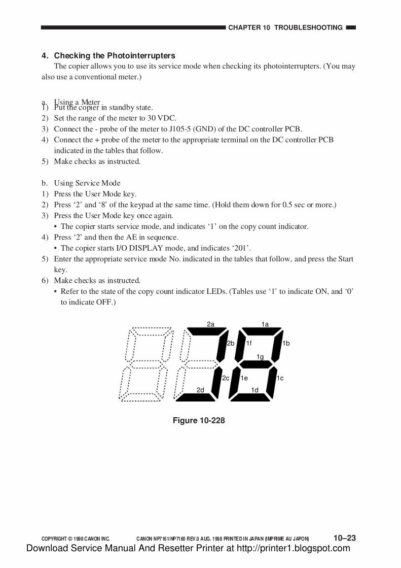
7/16/2019 Canon Np7161-Np7160 Copier Sm
http://slidepdf.com/reader/full/canon-np7161-np7160-copier-sm 253/345
COPYRIGHT © 1998 CANON INC. CANON NP7161/NP7160 REV.0 AUG. 1998 PRINTED IN JAPAN (IMPRIME AU JAPON)
CHAPTER 10 TROUBLESHOOTING
10–23
4. Checking the Photointerrupters
The copier allows you to use its service mode when checking its photointerrupters. (You may
also use a conventional meter.)
a. Using a Meter1) Put the copier in standby state.
2) Set the range of the meter to 30 VDC.
3) Connect the - probe of the meter to J105-5 (GND) of the DC controller PCB.
4) Connect the + probe of the meter to the appropriate terminal on the DC controller PCB
indicated in the tables that follow.
5) Make checks as instructed.
b. Using Service Mode
1) Press the User Mode key.
2) Press ‘2’ and ‘8’ of the keypad at the same time. (Hold them down for 0.5 sec or more.)
3) Press the User Mode key once again.
• The copier starts service mode, and indicates ‘1’ on the copy count indicator.
4) Press ‘2’ and then the AE in sequence.
• The copier starts I/O DISPLAY mode, and indicates ‘201’.
5) Enter the appropriate service mode No. indicated in the tables that follow, and press the Start
key.
6) Make checks as instructed.
• Refer to the state of the copy count indicator LEDs. (Tables use ‘1’ to indicate ON, and ‘0’
to indicate OFF.)
Figure 10-228
1a
1g
1b
1c
1f
1e
1d
2a
2b
2c
2d
Download Service Manual And Resetter Printer at http://printer1.blogspot.com
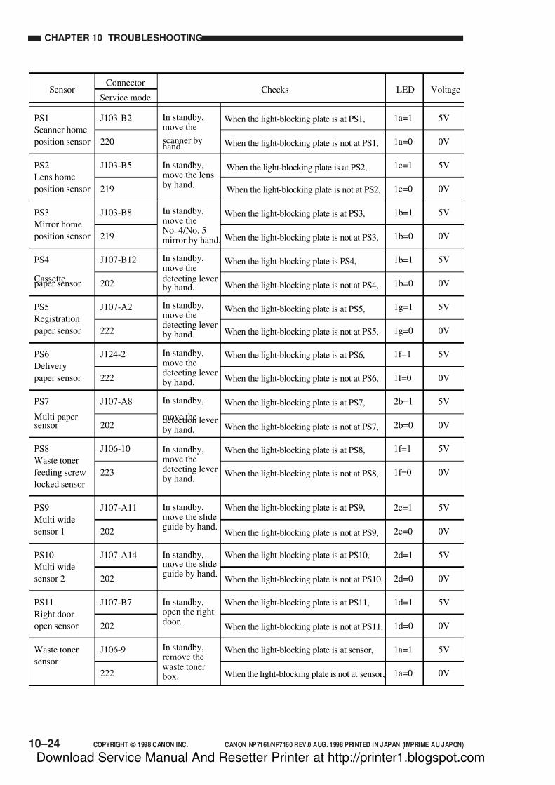
7/16/2019 Canon Np7161-Np7160 Copier Sm
http://slidepdf.com/reader/full/canon-np7161-np7160-copier-sm 254/345
CHAPTER 10 TROUBLESHOOTING
COPYRIGHT © 1998 CANON INC. CANON NP7161/NP7160 REV.0 AUG. 1998 PRINTED IN JAPAN (IMPRIME AU JAPON)10–24
Sensor
PS1
Scanner home
position sensor
PS2
Lens home
position sensor
PS3
Mirror home
position sensor
PS4
Cassettepaper sensor
PS5
Registration
paper sensor
PS6
Delivery
paper sensor
PS7
Multi papersensor
PS8
Waste toner
feeding screw
locked sensor
PS9
Multi wide
sensor 1
PS10
Multi wide
sensor 2
PS11
Right door
open sensor
Waste toner
sensor
J103-B2
220
J103-B5
219
J103-B8
219
J107-B12
202
J107-A2
222
J124-2
222
J107-A8
202
J106-10
223
J107-A11
202
J107-A14
202
J107-B7
202
J106-9
222
1a=1
1a=0
1c=1
1c=0
1b=1
1b=0
1b=1
1b=0
1g=1
1g=0
1f=1
1f=0
2b=1
2b=0
1f=1
1f=0
2c=1
2c=0
2d=1
2d=0
1d=1
1d=0
1a=1
1a=0
5V
0V
5V
0V
5V
0V
5V
0V
5V
0V
5V
0V
5V
0V
5V
0V
5V
0V
5V
0V
5V
0V
5V
0V
When the light-blocking plate is at PS1,
When the light-blocking plate is not at PS1,
When the light-blocking plate is at PS2,
When the light-blocking plate is not at PS2,
In standby,move the
scanner byhand.
In standby,move the lensby hand.
In standby,move theNo. 4/No. 5mirror by hand.
In standby,move the
detecting leverby hand.
In standby,move thedetecting leverby hand.
In standby,move thedetecting leverby hand.
In standby,
move thedetection leverby hand.
In standby,move thedetecting leverby hand.
In standby,move the slideguide by hand.
In standby,move the slideguide by hand.
In standby,open the rightdoor.
In standby,remove thewaste tonerbox.
Checks LED VoltageConnector
Service mode
When the light-blocking plate is at PS3,
When the light-blocking plate is not at PS3,
When the light-blocking plate is PS4,
When the light-blocking plate is not at PS4,
When the light-blocking plate is at PS5,
When the light-blocking plate is not at PS5,
When the light-blocking plate is at PS6,
When the light-blocking plate is not at PS6,
When the light-blocking plate is at PS7,
When the light-blocking plate is not at PS7,
When the light-blocking plate is at PS8,
When the light-blocking plate is not at PS8,
When the light-blocking plate is at PS9,
When the light-blocking plate is not at PS9,
When the light-blocking plate is at PS10,
When the light-blocking plate is not at PS10,
When the light-blocking plate is at PS11,
When the light-blocking plate is not at PS11,
When the light-blocking plate is at sensor,
When the light-blocking plate is not at sensor,
Download Service Manual And Resetter Printer at http://printer1.blogspot.com
7/16/2019 Canon Np7161-Np7160 Copier Sm
http://slidepdf.com/reader/full/canon-np7161-np7160-copier-sm 255/345
COPYRIGHT © 1998 CANON INC. CANON NP7161/NP7160 REV.0 AUG. 1998 PRINTED IN JAPAN (IMPRIME AU JAPON)
CHAPTER 10 TROUBLESHOOTING
10–25
III. IMAGE FAULTS
A. Initial Checks
1. Checking the Site Environmenta. The power outlet must be exclusive, and must provide the rated voltage. (The power plug
must remain connected throughout day and night.)
b. The copier must not be installed in a high-temperature/-humidity environment (near a water
faucet, water boiler, humidifier), near a source of fire, or in a dusty area.
c. The copier must not be subjected to ammonium gas.
d. The copier must be kept away from direct sunshine. As necessary, provide curtains.
e. The site must be well ventilated.
f. The copier must be kept level.
g. The copier must remain powered throughout day and night.
Check to make sure that all above conditions are met.
2. Checking the Originals
Identify the problem as to its cause—original page or the copier.
a. As a rule, the Copy Density adjusting lever must be at the median graduations, and ‘U12:
density correction’ in user mode must be set to ‘0’.
b. Original pages with a reddish background can cause poor contrast.
EX. Slips (invoices) made on reddish paper.
c. Diazo copies and original pages with a high transparency can produce copies mistakenly
identified as “foggy” copies. Original pages prepared in light pencil, on the other hand, can
produce copies mistakenly identified as “light” copies.
3. Checking the Copyboard Cover and Copyboard Glass
If soiled, clean it using a solution of mild detergent or alcohol. If scratches are found, replace it.
Download Service Manual And Resetter Printer at http://printer1.blogspot.com

7/16/2019 Canon Np7161-Np7160 Copier Sm
http://slidepdf.com/reader/full/canon-np7161-np7160-copier-sm 256/345
CHAPTER 10 TROUBLESHOOTING
COPYRIGHT © 1998 CANON INC. CANON NP7161/NP7160 REV.0 AUG. 1998 PRINTED IN JAPAN (IMPRIME AU JAPON)10–26
4. Checking the Charging Assembly
a. Check each charging assembly for soiling and a fault on its charging wire (scratches).
b. Clean the charging wire and shield plate of each charging assembly. (If dirt cannot be
removed, replace it.)
c. Check the height of each charging wire.d. Check to make sure that each charging wire is not rusted.
f. Check to make sure that the anti-vibration rubber (of each charging assembly) is not
displaced.
5. Checking the Developing Assembly
a. Check to make sure that the rollers on both ends of the developing assembly are in contact
with the drum.
b. Check to make sure that the surface of the developing cylinder is coated with an even layer of
toner.
6. Checking the Paper
a. Check if the paper is of a type recommended by Canon.
b. Check if the paper is not moist.
Try using paper fresh out of package.
7. Checking the Periodically Replaced Parts
Replace those parts that have reached their service life as indicated in the Scheduled
Servicing Chart and the Periodically Replaced Parts Table.
8. OthersKeep in mind that bringing in a copier from a cold to warm room, as during installation in
winter, can cause condensation in its inside, causing various problems.
a. Condensation on the scanning system (glass, mirror, lens, etc.) can cause light images.
b. Condensation in the charging system can cause electric leakage.
c. Condensation on the pick-up/feeding guide plate can cause faulty feeding.
If condensation is noted, dry wipe the part or leave the copier powered for about one hour.
Caution:
If a discrepancy in density (between separation side and rear), light image, of foggingoccurs, try to correct the problem by following the “Image Adjustment Basic Procedure.”
Download Service Manual And Resetter Printer at http://printer1.blogspot.com

7/16/2019 Canon Np7161-Np7160 Copier Sm
http://slidepdf.com/reader/full/canon-np7161-np7160-copier-sm 257/345
COPYRIGHT © 1998 CANON INC. CANON NP7161/NP7160 REV.0 AUG. 1998 PRINTED IN JAPAN (IMPRIME AU JAPON)
CHAPTER 10 TROUBLESHOOTING
10–27
Download Service Manual And Resetter Printer at http://printer1.blogspot.com

7/16/2019 Canon Np7161-Np7160 Copier Sm
http://slidepdf.com/reader/full/canon-np7161-np7160-copier-sm 258/345
CHAPTER 10 TROUBLESHOOTING
COPYRIGHT © 1998 CANON INC. CANON NP7161/NP7160 REV.0 AUG. 1998 PRINTED IN JAPAN (IMPRIME AU JAPON)10–28
B. Image Fault Samples
not available
Download Service Manual And Resetter Printer at http://printer1.blogspot.com
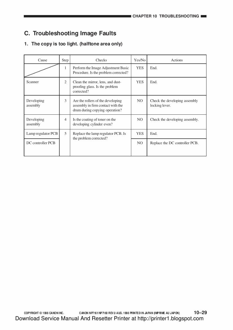
7/16/2019 Canon Np7161-Np7160 Copier Sm
http://slidepdf.com/reader/full/canon-np7161-np7160-copier-sm 259/345
COPYRIGHT © 1998 CANON INC. CANON NP7161/NP7160 REV.0 AUG. 1998 PRINTED IN JAPAN (IMPRIME AU JAPON)
CHAPTER 10 TROUBLESHOOTING
10–29
Step Checks Actions
1
2
3
4
5
End.
End.
Check the developing assembly
locking lever.
Check the developing assembly.
End.
Replace the DC controller PCB.
Cause
Perform the Image Adjustment Basic
Procedure. Is the problem corrected?
Clean the mirror, lens, and dust-
proofing glass. Is the problem
corrected?
Are the rollers of the developing
assembly in firm contact with the
drum during copying operation?
Is the coating of toner on the
developing cylinder even?
Replace the lamp regulator PCB. Is
the problem corrected?
Scanner
Developing
assembly
Developing
assembly
Lamp regulator PCB
DC controller PCB
Yes/No
YES
YES
NO
NO
YES
NO
C. Troubleshooting Image Faults
1. The copy is too light. (halftone area only)
Download Service Manual And Resetter Printer at http://printer1.blogspot.com
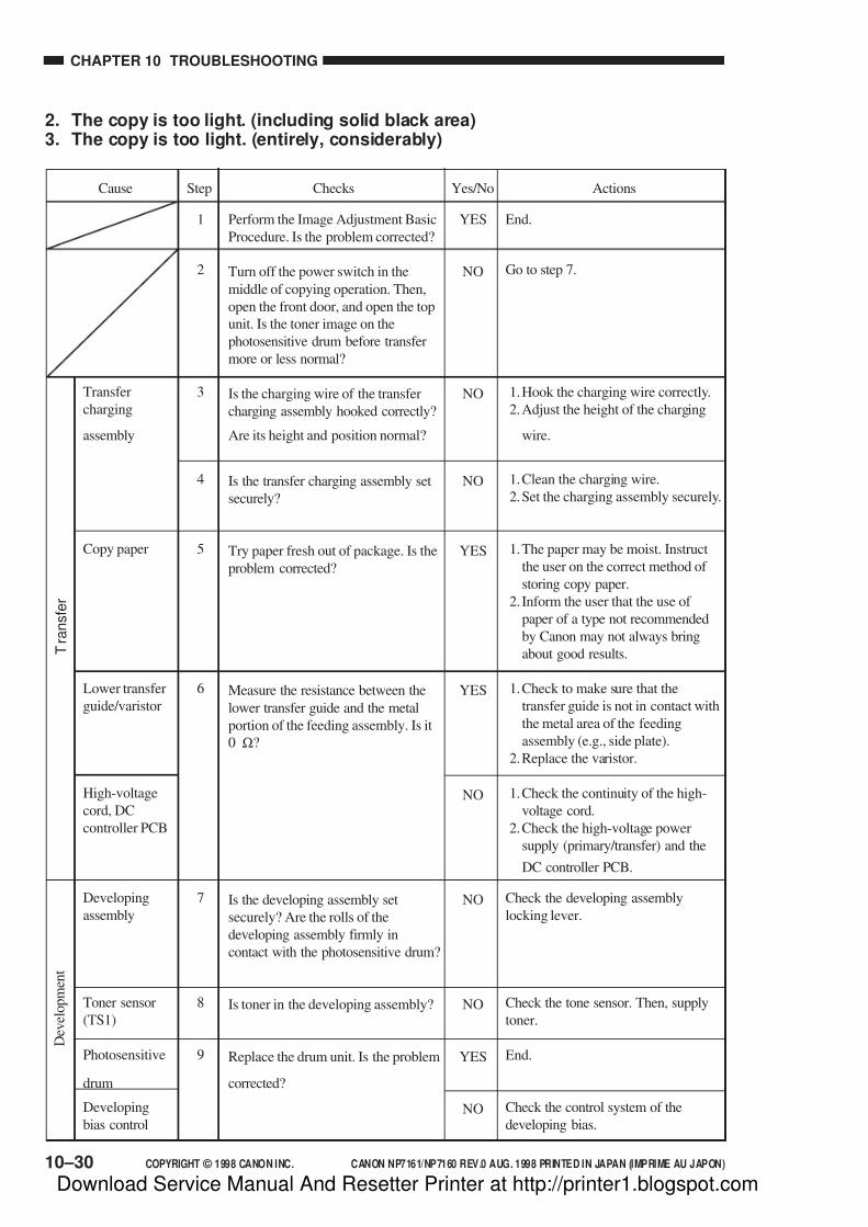
7/16/2019 Canon Np7161-Np7160 Copier Sm
http://slidepdf.com/reader/full/canon-np7161-np7160-copier-sm 260/345
CHAPTER 10 TROUBLESHOOTING
COPYRIGHT © 1998 CANON INC. CANON NP7161/NP7160 REV.0 AUG. 1998 PRINTED IN JAPAN (IMPRIME AU JAPON)10–30
1
2
3
4
5
6
7
8
9
Perform the Image Adjustment Basic
Procedure. Is the problem corrected?
Turn off the power switch in the
middle of copying operation. Then,
open the front door, and open the top
unit. Is the toner image on the
photosensitive drum before transfer
more or less normal?
Is the charging wire of the transfer
charging assembly hooked correctly?
Are its height and position normal?
Is the transfer charging assembly set
securely?
Try paper fresh out of package. Is the
problem corrected?
Measure the resistance between the
lower transfer guide and the metal
portion of the feeding assembly. Is it
0 Ω?
Is the developing assembly set
securely? Are the rolls of the
developing assembly firmly in
contact with the photosensitive drum?
Is toner in the developing assembly?
Replace the drum unit. Is the problem
corrected?
End.
Go to step 7.
1.Hook the charging wire correctly.
2.Adjust the height of the charging
wire.
1.Clean the charging wire.
2.Set the charging assembly securely.
1.The paper may be moist. Instruct
the user on the correct method of
storing copy paper.
2. Inform the user that the use of
paper of a type not recommended
by Canon may not always bring
about good results.
1.Check to make sure that the
transfer guide is not in contact with
the metal area of the feeding
assembly (e.g., side plate).
2.Replace the varistor.
1.Check the continuity of the high-
voltage cord.
2.Check the high-voltage power
supply (primary/transfer) and the
DC controller PCB.
Check the developing assembly
locking lever.
Check the tone sensor. Then, supply
toner.
End.
Check the control system of the
developing bias.
Step Checks Actions
YES
NO
NO
NO
YES
YES
NO
NO
NO
YES
NO
Yes/No
Transfer
charging
assembly
Copy paper
Lower transfer
guide/varistor
High-voltage
cord, DC
controller PCB
Developing
assembly
Toner sensor
(TS1)
Photosensitive
drum
Developing
bias control
T
r a n s f e r
D e v e l o p m e n t
Cause
2. The copy is too light. (including solid black area)3. The copy is too light. (entirely, considerably)
Download Service Manual And Resetter Printer at http://printer1.blogspot.com

7/16/2019 Canon Np7161-Np7160 Copier Sm
http://slidepdf.com/reader/full/canon-np7161-np7160-copier-sm 261/345
COPYRIGHT © 1998 CANON INC. CANON NP7161/NP7160 REV.0 AUG. 1998 PRINTED IN JAPAN (IMPRIME AU JAPON)
CHAPTER 10 TROUBLESHOOTING
10–31
4. The copy has uneven density. (front side dark)5. The copy has uneven density. (front side light)
Developing
assembly
Scanner
Pre-scanning lamp
(LA2)
Developing
assembly
Charging assembly,
Copy paper
1
2
3
4
5
Perform the Image Adjustment Basic
Procedure. Is the problem corrected?
Are the developing rolls of the
developing assembly in firm contact
with the photosensitive drum?
Clean the scanning lamp, reflecting
plate, side reflecting plate, mirror,
lens, and dust-proofing glass. Is the
problem corrected?
Does the pre-exposure lamp remain
on during copying?
Is the developing cylinder coated
with a uniform layer of toner?
End.
Check the developing assembly
locking lever.
End.
1.Replace the pre-exposure lamp.
2.Replace the DC controller PCB.
1.Clean the tip of the blade of the
developing assembly. (dry wiping)?
2.Clean the surface of the developing
cylinder.
3.Check to make sure that the toner
inside the developing assembly is
not displaced to one side.
1.Clean all charging wires once
again, and check the height of thecharging wires once again.
2.Try replacing the copy paper.
Step Checks ActionsYes/NoCause
YES
NO
YES
NO
NO
YES
Download Service Manual And Resetter Printer at http://printer1.blogspot.com

7/16/2019 Canon Np7161-Np7160 Copier Sm
http://slidepdf.com/reader/full/canon-np7161-np7160-copier-sm 262/345
CHAPTER 10 TROUBLESHOOTING
COPYRIGHT © 1998 CANON INC. CANON NP7161/NP7160 REV.0 AUG. 1998 PRINTED IN JAPAN (IMPRIME AU JAPON)10–32
6. The copy is foggy. (overall)
Scanner
Pre-exposure lamp
(LA2),
DC controller PCB
Developing roll
Developing cylinder
Scanner lamp (LA1)
High-voltage power
supply PCB
Lamp regulator PCB
DC controller PCB
1
2
3
4
5
6
7
8
Perform the Image Adjustment BasicProcedure. Is the problem corrected?
Clean the scanning lamp, reflecting
plate, side reflecting plate, mirror,
lens, and dust-proofing glass. Is the
problem corrected?
Does the pre-exposure lamp remain
on during copying?
Are the developing rolls worn?
Is the developing cylinder worn?
Replace the scanning lamp. Is the
problem corrected?
Replace the high-voltage power
supply PCB. Is the problem
corrected?
Replace the lamp regulator PCB. Is
the problem corrected?
Checks ActionsCause
YES
YES
NO
YES
YES
YES
YES
YES
NO
Yes/NoStep
End.
End.
1.Replace the pre-exposure lamp.
2.Replace the DC controller PCB.
Replace the developing rolls.
Replace the developing cylinder.
End.
End.
End.
Replace the DC controller PCB.
Download Service Manual And Resetter Printer at http://printer1.blogspot.com

7/16/2019 Canon Np7161-Np7160 Copier Sm
http://slidepdf.com/reader/full/canon-np7161-np7160-copier-sm 263/345
COPYRIGHT © 1998 CANON INC. CANON NP7161/NP7160 REV.0 AUG. 1998 PRINTED IN JAPAN (IMPRIME AU JAPON)
CHAPTER 10 TROUBLESHOOTING
10–33
7. The copy is foggy. (vertical)8. The copy has black lines. (vertical, fuzzy, thick)
Primary charging
assembly
Scanner
Pre-exposure lamp
(LA2)
Developing
assembly
Fixing assembly
1
2
3
4
Clean the primary charging wire, grid
plate, and shielding plate. Is the
problem corrected?
Clean the scanning lamp, reflecting
plate, side reflecting plate, mirror,
lens, and dust-proofing glass. Is the
problem corrected?
Clean the pre-exposure lamp. Is the
problem corrected?
Is the developing cylinder coated
with a uniform layer of toner?
End.
End.
End.
Check and clean the edge of the blade
of the developing assembly.
Check the fixing assembly.
Step Checks ActionsYes/NoCause
YES
YES
YES
NO
YES
9. The copy has black lines. (vertical, thin)
Transfer guide
Photosensitive drum
Developing system,
Exposure system
Fixing assembly
1
2
3
4
Press the Copy Start key, and turn off
the power switch while the copy
paper is in the feeding assembly. At
this time, does the copy image before
it goes through the fixing assembly
have black lines?
Is the transfer guide soiled
(particularly the transfer upper guide)?
Are there scratches or black lines in
the peripheral direction of the surface
of the photosensitive drum?
Are there scratches or black lines in
the peripheral direction of the surface
of the fixing upper roller?
Go to step 4.
Clean the transfer guide.
Replace the drum unit. If scratches
are found, be sure to find out the
cause.
Check the developing system and the
exposure system.
1.Replace the upper roller.
2.Check the separation claw.
Check to make sure that the fixing
assembly inlet is not soiled.
Checks ActionsCause
NO
YES
YES
NO
YES
NO
Yes/NoStep
Download Service Manual And Resetter Printer at http://printer1.blogspot.com
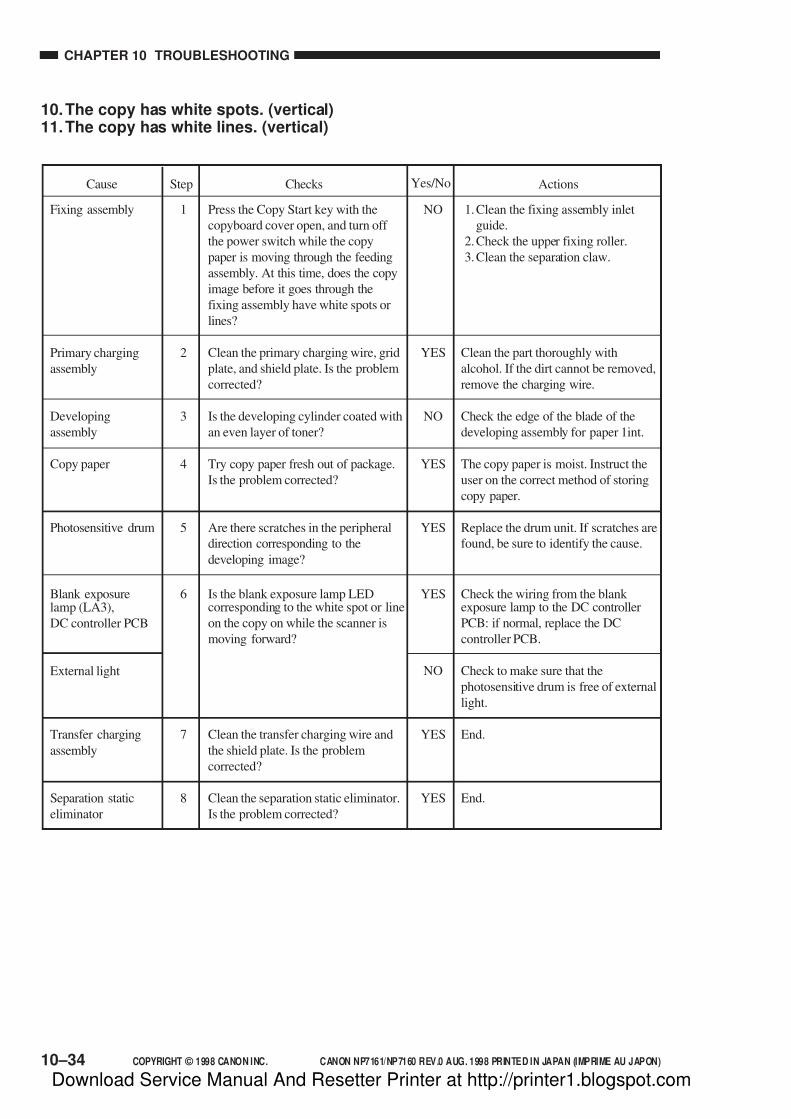
7/16/2019 Canon Np7161-Np7160 Copier Sm
http://slidepdf.com/reader/full/canon-np7161-np7160-copier-sm 264/345
CHAPTER 10 TROUBLESHOOTING
COPYRIGHT © 1998 CANON INC. CANON NP7161/NP7160 REV.0 AUG. 1998 PRINTED IN JAPAN (IMPRIME AU JAPON)10–34
10.The copy has white spots. (vertical)11.The copy has white lines. (vertical)
Fixing assembly
Primary charging
assembly
Developing
assembly
Copy paper
Photosensitive drum
Blank exposurelamp (LA3),
DC controller PCB
External light
Transfer charging
assembly
Separation static
eliminator
Press the Copy Start key with the
copyboard cover open, and turn off
the power switch while the copy
paper is moving through the feeding
assembly. At this time, does the copy
image before it goes through the
fixing assembly have white spots or
lines?
Clean the primary charging wire, grid
plate, and shield plate. Is the problem
corrected?
Is the developing cylinder coated with
an even layer of toner?
Try copy paper fresh out of package.
Is the problem corrected?
Are there scratches in the peripheral
direction corresponding to the
developing image?
Is the blank exposure lamp LEDcorresponding to the white spot or line
on the copy on while the scanner is
moving forward?
Clean the transfer charging wire and
the shield plate. Is the problem
corrected?
Clean the separation static eliminator.
Is the problem corrected?
1.Clean the fixing assembly inlet
guide.
2.Check the upper fixing roller.
3.Clean the separation claw.
Clean the part thoroughly with
alcohol. If the dirt cannot be removed,
remove the charging wire.
Check the edge of the blade of the
developing assembly for paper 1int.
The copy paper is moist. Instruct the
user on the correct method of storing
copy paper.
Replace the drum unit. If scratches are
found, be sure to identify the cause.
Check the wiring from the blank exposure lamp to the DC controller
PCB: if normal, replace the DC
controller PCB.
Check to make sure that the
photosensitive drum is free of external
light.
End.
End.
ActionsCause
NO
YES
NO
YES
YES
YES
NO
YES
YES
Yes/NoChecksStep
1
2
3
4
5
6
7
8
Download Service Manual And Resetter Printer at http://printer1.blogspot.com
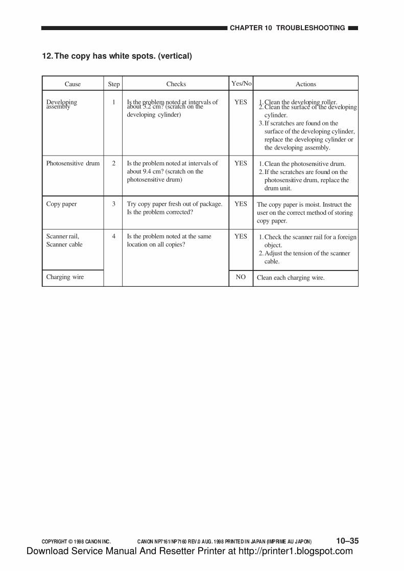
7/16/2019 Canon Np7161-Np7160 Copier Sm
http://slidepdf.com/reader/full/canon-np7161-np7160-copier-sm 265/345
COPYRIGHT © 1998 CANON INC. CANON NP7161/NP7160 REV.0 AUG. 1998 PRINTED IN JAPAN (IMPRIME AU JAPON)
CHAPTER 10 TROUBLESHOOTING
10–35
12.The copy has white spots. (vertical)
Developingassembly
Photosensitive drum
Copy paper
Scanner rail,
Scanner cable
Charging wire
1
2
3
4
Is the problem noted at intervals of about 3.2 cm? (scratch on the
developing cylinder)
Is the problem noted at intervals of
about 9.4 cm? (scratch on the
photosensitive drum)
Try copy paper fresh out of package.
Is the problem corrected?
Is the problem noted at the same
location on all copies?
1.Clean the developing roller.2.Clean the surface of the developing
cylinder.
3. If scratches are found on the
surface of the developing cylinder,
replace the developing cylinder or
the developing assembly.
1.Clean the photosensitive drum.
2. If the scratches are found on the
photosensitive drum, replace the
drum unit.
The copy paper is moist. Instruct the
user on the correct method of storing
copy paper.
1.Check the scanner rail for a foreign
object.
2.Adjust the tension of the scanner
cable.
Clean each charging wire.
ActionsCause Checks
YES
YES
YES
YES
NO
Step Yes/No
Download Service Manual And Resetter Printer at http://printer1.blogspot.com
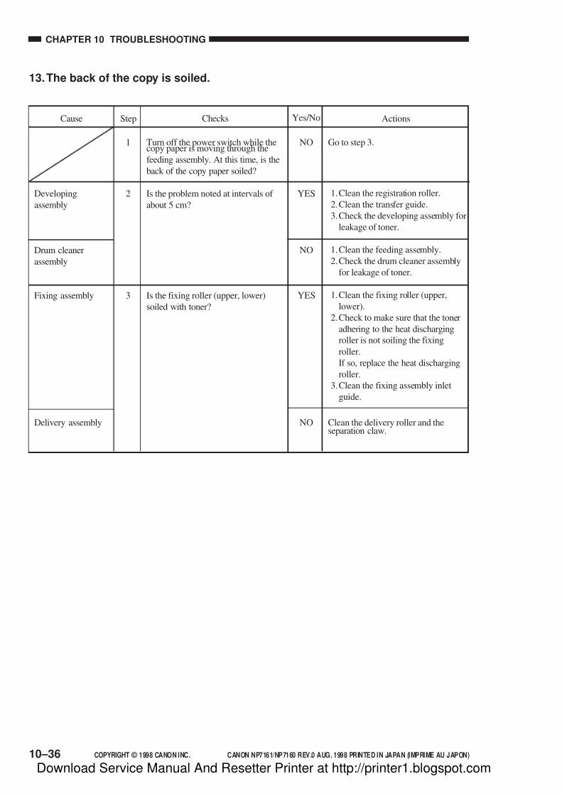
7/16/2019 Canon Np7161-Np7160 Copier Sm
http://slidepdf.com/reader/full/canon-np7161-np7160-copier-sm 266/345
CHAPTER 10 TROUBLESHOOTING
COPYRIGHT © 1998 CANON INC. CANON NP7161/NP7160 REV.0 AUG. 1998 PRINTED IN JAPAN (IMPRIME AU JAPON)10–36
13.The back of the copy is soiled.
Developing
assembly
Drum cleaner
assembly
Fixing assembly
Delivery assembly
1
2
3
Turn off the power switch while thecopy paper is moving through the
feeding assembly. At this time, is the
back of the copy paper soiled?
Is the problem noted at intervals of
about 5 cm?
Is the fixing roller (upper, lower)
soiled with toner?
Go to step 3.
1.Clean the registration roller.
2.Clean the transfer guide.
3.Check the developing assembly for
leakage of toner.
1.Clean the feeding assembly.
2.Check the drum cleaner assembly
for leakage of toner.
1.Clean the fixing roller (upper,
lower).
2.Check to make sure that the toner
adhering to the heat discharging
roller is not soiling the fixing
roller.
If so, replace the heat discharging
roller.
3.Clean the fixing assembly inlet
guide.
Clean the delivery roller and theseparation claw.
ActionsCause Checks
NO
YES
NO
YES
NO
Step Yes/No
Download Service Manual And Resetter Printer at http://printer1.blogspot.com

7/16/2019 Canon Np7161-Np7160 Copier Sm
http://slidepdf.com/reader/full/canon-np7161-np7160-copier-sm 267/345
COPYRIGHT © 1998 CANON INC. CANON NP7161/NP7160 REV.0 AUG. 1998 PRINTED IN JAPAN (IMPRIME AU JAPON)
CHAPTER 10 TROUBLESHOOTING
10–37
14.The copy has faulty fixing.
Fixing roller (upper/ lower)
Fixing heater (H1)
Fixing lower heater
pressure
Copy paper
1
2
3
Is the problem noted vertically?
Does the fixing heater (H1) turn on
immediately after power-on?
Is the nip of the fixing assembly as
indicated?
Check the fixing roller (upper, lower)for scratches.
See the “Fixing heater fails to turn
on.”
Adjust the fixing lower roller
pressure.
Try recommended paper. If the results
are good, advise the user to use
recommended paper.
ActionsCause Yes/NoChecks
YES
NO
NO
YES
Step
Download Service Manual And Resetter Printer at http://printer1.blogspot.com
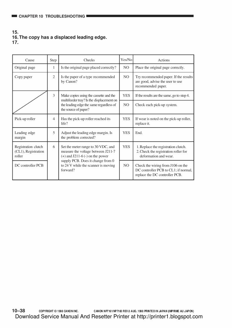
7/16/2019 Canon Np7161-Np7160 Copier Sm
http://slidepdf.com/reader/full/canon-np7161-np7160-copier-sm 268/345
CHAPTER 10 TROUBLESHOOTING
COPYRIGHT © 1998 CANON INC. CANON NP7161/NP7160 REV.0 AUG. 1998 PRINTED IN JAPAN (IMPRIME AU JAPON)10–38
15.16.The copy has a displaced leading edge.17.
Original page
Copy paper
Pick-up roller
Leading edge
margin
Registration clutch
(CL1), Registration
roller
DC controller PCB
1
2
3
4
5
6
Is the original page placed correctly?
Is the paper of a type recommended
by Canon?
Make copies using the cassette and the
multifeeder tray? Is the displacement on
the leading edge the same regardless of
the source of paper?
Has the pick-up roller reached its
life?
Adjust the leading edge margin. Is
the problem corrected?
Set the meter range to 30 VDC, and
measure the voltage between J211-7
(+) and J211-6 (-) on the power
supply PCB. Does it change from 0
to 24 V while the scanner is moving
forward?
Place the original page correctly.
Try recommended paper. If the results
are good, advise the user to use
recommended paper.
If the results are the same, go to step 4.
Check each pick-up system.
If wear is noted on the pick-up roller,
replace it.
End.
1.Replace the registration clutch.
2.Check the registration roller for
deformation and wear.
Check the wiring from J106 on the
DC controller PCB to CL1; if normal,
replace the DC controller PCB.
ActionsCause Yes/NoChecks
NO
NO
YES
NO
YES
YES
YES
NO
Step
Download Service Manual And Resetter Printer at http://printer1.blogspot.com

7/16/2019 Canon Np7161-Np7160 Copier Sm
http://slidepdf.com/reader/full/canon-np7161-np7160-copier-sm 269/345
COPYRIGHT © 1998 CANON INC. CANON NP7161/NP7160 REV.0 AUG. 1998 PRINTED IN JAPAN (IMPRIME AU JAPON)
CHAPTER 10 TROUBLESHOOTING
10–39
18.The copy has a blurred image.
Scanner cable
Scanner rail
Photosensitive drum
Developing gear
Drum drive system
1
2
3
4
Does the cable wind on the cablepulley in layers while the scanner is
moving?
Move the No. 1 mirror mount slowly
by hand. Does it move smoothly?
Is the problem noted at intervals of
about 9.4 cm?
Is the problem noted at intervals of
about 3.2 cm?
1.Route the cable once again.2. If the cable is twisted or frayed,
replace it.
Clean the surface of the scanner rail
with alcohol. Then, apply a small
amount of lubricant.
1.Check the drum gear.
2.Check the end of the drum (in
contact with the developing roller)
for scratches and protrusions.
Check the developing assembly.
Check the drum drive system.
ActionsCause Yes/NoChecks
YES
NO
YES
YES
NO
Step
19.The copy is foggy. (horizontally)
Scanning lamp
(LA1), Lamp
regulator PCB
Developing roller
Developing bias
Scanner
Feeding assembly
Is the problem noted at the same
location on all copies made in Direct?
Does the scanning lamp flicker when
the scanner is moving forward?
Is the developing roller soiled with
toner, is the roller deformed, or is the
area in contact with the developing
roller (photosensitive drum) soiled
with toner?
Is the developing bias applied
correctly?
Make a copy in Reduce, and compare
it with a copy made in Direct. Is the
problem noted in a different location?
ActionsCause Yes/NoChecks
Go to step 4.
Check the scanning lamp and the
lamp regulator PCB.
Clean or, if necessary, replace the
developing roller.
Remove the developing assembly,
and check the wiring; then, set it once
again.
Check the scanning system.
Check the feeding assembly.
YES
YES
YES
NO
YES
NO
Step
1
2
3
4
5
Download Service Manual And Resetter Printer at http://printer1.blogspot.com

7/16/2019 Canon Np7161-Np7160 Copier Sm
http://slidepdf.com/reader/full/canon-np7161-np7160-copier-sm 270/345
CHAPTER 10 TROUBLESHOOTING
COPYRIGHT © 1998 CANON INC. CANON NP7161/NP7160 REV.0 AUG. 1998 PRINTED IN JAPAN (IMPRIME AU JAPON)10–40
20.The copy has poor sharpness.
Copyboard glass
Mirror
Scanner
Lens drive assembly,
No. 4/No. 5 mirror
drive assembly
Photosensitive drum
1
2
3
4
Is the copyboard glass soiled with oilor the like?
Is the horizontal reproduction ratio in
Direct as indicated?
Clean the scanning lamp, reflecting
plate, mirror, lens, and dust-proofing
glass. Is the problem corrected?
Is there dirt or foreign object in the
path of the lens and the No. 4/ No. 5
mirror? Does the part, when pushed
by hand, move smoothly?
Clean the copyboard glass.
Adjust the distance between the No. 1
mirror and the No. 2 mirror.
End.
Remove the dirt and foreign object.
As necessary, clean and lubricate.
Replace the drum unit.
YES
NO
YES
YES
NO
Yes/No ActionsChecksStepCause
Download Service Manual And Resetter Printer at http://printer1.blogspot.com

7/16/2019 Canon Np7161-Np7160 Copier Sm
http://slidepdf.com/reader/full/canon-np7161-np7160-copier-sm 271/345
COPYRIGHT © 1998 CANON INC. CANON NP7161/NP7160 REV.0 AUG. 1998 PRINTED IN JAPAN (IMPRIME AU JAPON)
CHAPTER 10 TROUBLESHOOTING
10–41
21.The copy is blank.
Drum unit
Developing
assembly
Primary charging
assembly
Developing
assembly
DC controller PCB
Scanning lamp
(LA1)
Connector
High-voltage cord
High-voltage power
supply (primary/ transfer)
1
2
3
4
5
6
7
8
Is the drum unit set securely?
Is the developing assembly set
securely?
Is the primary charging wire broken?
Is the developing assembly locked to
the drum?
Does the blank exposure lamp remain
off while the scanner is moving
forward?
Does the scanning lamp remain on
during copying operation?
Are the connectors on each PCB
connected securely?
Is there continuity between high-
voltage cords connected to each
charging assembly?
Remove and set the drum unit onceagain.
Remove and set the developing
assembly securely.
Spring the charging wire.
Check the developing assembly
locking lever.
Check the DC controller PCB.
Make checks as instructed under “The
scanning lamp fails to turn on.”
Connect the connectors securely.
Replace the high-voltage cord.
Check the high-voltage power supply
(primary/transfer).
Yes/No ActionsChecksCause
NO
NO
YES
NO
NO
NO
NO
NO
YES
Step
22.The copy is solid black.
Does the scanning lamp remain on
during copying operation?
Make checks according to the
instructions under “The scanning
lamp fails to turns off.”
Yes/No ActionsChecksStepCause
NO1
Download Service Manual And Resetter Printer at http://printer1.blogspot.com
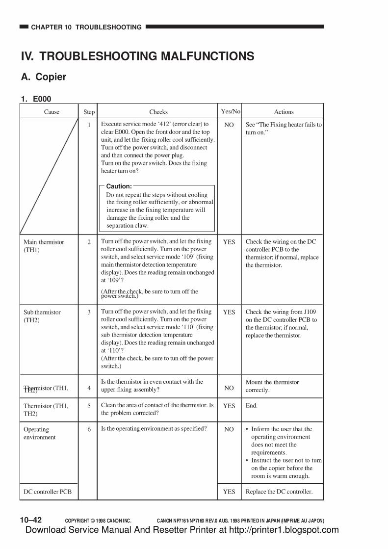
7/16/2019 Canon Np7161-Np7160 Copier Sm
http://slidepdf.com/reader/full/canon-np7161-np7160-copier-sm 272/345
CHAPTER 10 TROUBLESHOOTING
10–42 COPYRIGHT © 1998 CANON INC. CANON NP7161/NP7160 REV.0 AUG. 1998 PRINTED IN JAPAN (IMPRIME AU JAPON)
Main thermistor
(TH1)
Sub thermistor
(TH2)
Thermistor (TH1,TH2)
Thermistor (TH1,
TH2)
Operating
environment
DC controller PCB
Execute service mode ‘412’ (error clear) to
clear E000. Open the front door and the top
unit, and let the fixing roller cool sufficiently.
Turn off the power switch, and disconnect
and then connect the power plug.
Turn on the power switch. Does the fixing
heater turn on?
Caution:
Do not repeat the steps without coolingthe fixing roller sufficiently, or abnormal
increase in the fixing temperature will
damage the fixing roller and the
separation claw.
Turn off the power switch, and let the fixing
roller cool sufficiently. Turn on the power
switch, and select service mode ‘109’ (fixing
main thermistor detection temperature
display). Does the reading remain unchanged
at ‘109’?
(After the check, be sure to turn off thepower switch.)
Turn off the power switch, and let the fixing
roller cool sufficiently. Turn on the power
switch, and select service mode ‘110’ (fixing
sub thermistor detection temperature
display). Does the reading remain unchanged
at ‘110’?
(After the check, be sure to tun off the power
switch.)
Is the thermistor in even contact with the
upper fixing assembly?
Clean the area of contact of the thermistor. Is
the problem corrected?
Is the operating environment as specified?
See “The Fixing heater fails to
turn on.”
Check the wiring on the DC
controller PCB to the
thermistor; if normal, replace
the thermistor.
Check the wiring from J109
on the DC controller PCB to
the thermistor; if normal,
replace the thermistor.
Mount the thermistor
correctly.
End.
• Inform the user that the
operating environment
does not meet the
requirements.
• Instruct the user not to turn
on the copier before the
room is warm enough.
Replace the DC controller.
IV. TROUBLESHOOTING MALFUNCTIONS
A. Copier
1. E000
ActionsChecksStepCause Yes/No
1
2
3
4
5
6
NO
YES
YES
NO
YES
NO
YES
Download Service Manual And Resetter Printer at http://printer1.blogspot.com

7/16/2019 Canon Np7161-Np7160 Copier Sm
http://slidepdf.com/reader/full/canon-np7161-np7160-copier-sm 273/345
COPYRIGHT © 1998 CANON INC. CANON NP7161/NP7160 REV.0 AUG. 1998 PRINTED IN JAPAN (IMPRIME AU JAPON)
CHAPTER 10 TROUBLESHOOTING
10–43
2. E001
Thermistor (TH1,
TH2)
DC controller PCB
Triac
DC controller PCB
1
2
3
Execute service mode ‘412’ (error clear) toclear E001. Open the front door and the top
unit, and let the fixing roller cool
sufficiently.
Turn on the power switch. Is E001 indicated
immediately after power-on?
Turn off the power switch, and disconnect
J108 and J109 on the DC controller PCB.
Connect the probes to J108-2 and J108-3
and then J109-1 and J109-2 on the harness
side. Is the resistance about 0 Ω? (After the
check, be sure to connect J108 and J109.)
Replace the power supply PCB. Is the
problem corrected?
ActionsChecksStepCause
Go to step 3.
Replace the thermistor.
Replace the DC controller
PCB.
End.
Check the wiring from the
power supply PCB to the DC
controller PCB; if normal,
replace the DC controller PCB.
NO
YES
NO
YES
NO
Yes/No
Download Service Manual And Resetter Printer at http://printer1.blogspot.com

7/16/2019 Canon Np7161-Np7160 Copier Sm
http://slidepdf.com/reader/full/canon-np7161-np7160-copier-sm 274/345
CHAPTER 10 TROUBLESHOOTING
10–44 COPYRIGHT © 1998 CANON INC. CANON NP7161/NP7160 REV.0 AUG. 1998 PRINTED IN JAPAN (IMPRIME AU JAPON)
3. E002/E003
1
2
3
4
5
6
Execute service mode ‘412’ (error clear) toclear E002 or E003. Open the front door and
the top unit, and let the fixing roller cool
sufficiently.
Turn on the power switch. Does any of the
following apply?
• The fixing heater fails to turn on.
• E000
Turn off the power switch, and let the fixing
roller cool sufficiently. Turn on the power
switch, and select service mode ‘109’.
(fixing main thermistor detection
temperature display)
Does the reading remain unchanged at
‘109’? (After the check, be sure to turn off
the power switch.)
Turn off the power switch, and let the fixing
roller cool sufficiently. Turn on the power
switch, and select service mode ‘110’.
(fixing sub thermistor temperature display)
Does the reading remain unchanged at
‘110’? (After the check, be sure to turn off
the power switch.)
Is the thermistor in even contact with the
upper fixing roller?
Clean the area of contact of the thermistor. Is
the problem corrected?
Is the operating environment as indicated?
See the appropriate section.
Check the wiring from J108
on the DC controller PCB to
the thermistor; if normal,
replace the thermistor.
Check the wiring from J109
on the DC controller PCB to
the thermistor; if normal,
replace the thermistor.
Mount the thermistor
correctly.
End.
• Inform the user that the
operating environment
does not meet the
requirements.
• Instruct the user not to turn
on the copier before theroom is warm enough.
Replace the DC controller
PCB.
Main thermistor
Sub thermistor
(TH2)
Thermistor
(TH1, TH2)
Thermistor
(TH1, TH2)
Operating
environment
DC controller PCB
ActionsChecksStepCause Yes/No
YES
YES
YES
NO
YES
NO
YES
Download Service Manual And Resetter Printer at http://printer1.blogspot.com

7/16/2019 Canon Np7161-Np7160 Copier Sm
http://slidepdf.com/reader/full/canon-np7161-np7160-copier-sm 275/345
COPYRIGHT © 1998 CANON INC. CANON NP7161/NP7160 REV.0 AUG. 1998 PRINTED IN JAPAN (IMPRIME AU JAPON)
CHAPTER 10 TROUBLESHOOTING
10–45
4. E004
Fixing heater (H1)
Triac
DC controller PCB
1
2
NO
YES
NO
Execute service mode ‘412’ (error clear) toclear E004.
Turn on the power switch. Does the fixing
heater turn on?
Replace the power supply PCB. Is the
problem corrected?
See “The fixing heater fails toturn on.”
End.
Check the wiring from the
power supply PCB to the DC
controller PCB; if normal,
replace the DC controller
PCB.
5. E010
Connector
Power supply PCB
Main motor (M1)
DC controller PCB
1
2
3
NO
NO
YES
NO
Are all connectors of the main motor (M1)
connected?
Turn on the power switch. Set the meterrange to 30 VDC, and connect the probes to
J209-4 (+) and J209-3 (-) on the DC
controller PCB. Is the voltage about 24 V?
Replace the main motor. Is the problem
corrected?
Connect the connectors.
See “DC power is absent.”
End.
Replace the DC controller
PCB.
ActionsChecksStepCause Yes/No
ActionsChecksCause Yes/NoStep
Download Service Manual And Resetter Printer at http://printer1.blogspot.com

7/16/2019 Canon Np7161-Np7160 Copier Sm
http://slidepdf.com/reader/full/canon-np7161-np7160-copier-sm 276/345
CHAPTER 10 TROUBLESHOOTING
10–46 COPYRIGHT © 1998 CANON INC. CANON NP7161/NP7160 REV.0 AUG. 1998 PRINTED IN JAPAN (IMPRIME AU JAPON)
6. E013
Waste toner feedingscrew
Waste toner feeding
screw locked sensor
(PS8)
DC controller PCB
1
2
NO
NO
YES
Is the flag of the waste toner feeding screwlocked sensor rotating when the main motor
is rotating?
Is the waste toner feeding screw locked
sensor normal? (See the instructions on how
to check the photointerrupters.)
Remove the drum unit, andturn the feeding screw by
hand. If it rotates easily, check
how it is mounted. If it does
not turn, replace the drum unit,
and remove the cause.
Check the wiring from the DC
controller PCB to PS8; if
normal, replace PS8.
Replace the DC controller
PCB.
ActionsChecksStepCause Yes/No
7. E030
Total copy counter
(CNT1)
Total copy counter
(CNT1)
DC controller PCB
1
2
NO
YES
NO
Turn off the power switch, and disconnect
J102 from the DC controller PCB. Set the
meter range to 1 KΩ, and connect the probes
to J102-A11 and J102-A10. Is the resistanceabout 500Ω?
Connect J102 to the DC controller PCB, and
turn on the power switch. Set the meter range
to 30 VCD, and connect the probes J102-
A11 (+) and J102-A10 (-) on the DC
controller PCB. Does the voltage change
from about 0 to about 24 and then to about 0
V when the Start key is pressed?
Check the wiring from the DC
controller PCB to the counter;
if normal, replace the counter.
Replace the counter.
Replace the DC controller
PCB.
ActionsChecksStepCause Yes/No
Download Service Manual And Resetter Printer at http://printer1.blogspot.com
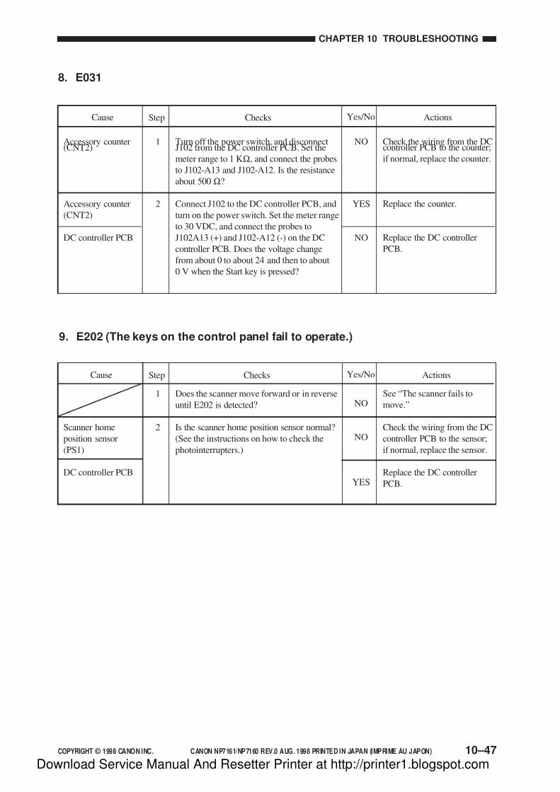
7/16/2019 Canon Np7161-Np7160 Copier Sm
http://slidepdf.com/reader/full/canon-np7161-np7160-copier-sm 277/345
COPYRIGHT © 1998 CANON INC. CANON NP7161/NP7160 REV.0 AUG. 1998 PRINTED IN JAPAN (IMPRIME AU JAPON)
CHAPTER 10 TROUBLESHOOTING
10–47
8. E031
Accessory counter(CNT2)
Accessory counter
(CNT2)
DC controller PCB
1
2
NO
YES
NO
Turn off the power switch, and disconnectJ102 from the DC controller PCB. Set the
meter range to 1 KΩ, and connect the probes
to J102-A13 and J102-A12. Is the resistance
about 500 Ω?
Connect J102 to the DC controller PCB, and
turn on the power switch. Set the meter range
to 30 VDC, and connect the probes to
J102A13 (+) and J102-A12 (-) on the DC
controller PCB. Does the voltage change
from about 0 to about 24 and then to about
0 V when the Start key is pressed?
Check the wiring from the DCcontroller PCB to the counter;
if normal, replace the counter.
Replace the counter.
Replace the DC controller
PCB.
ActionsChecksStepCause Yes/No
9. E202 (The keys on the control panel fail to operate.)
NO
NO
YES
Scanner home
position sensor
(PS1)
DC controller PCB
1
2
Does the scanner move forward or in reverse
until E202 is detected?
Is the scanner home position sensor normal?
(See the instructions on how to check the
photointerrupters.)
See “The scanner fails to
move.”
Check the wiring from the DC
controller PCB to the sensor;
if normal, replace the sensor.
Replace the DC controller
PCB.
ActionsChecksCause Step Yes/No
Download Service Manual And Resetter Printer at http://printer1.blogspot.com
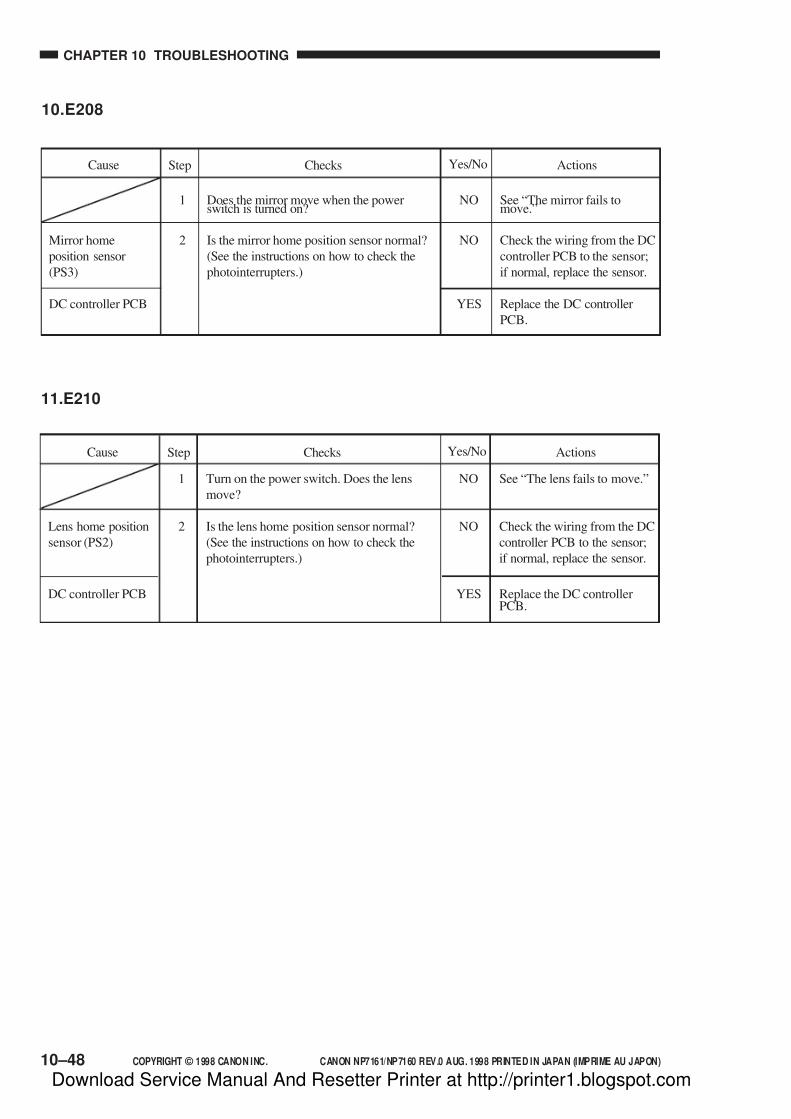
7/16/2019 Canon Np7161-Np7160 Copier Sm
http://slidepdf.com/reader/full/canon-np7161-np7160-copier-sm 278/345
CHAPTER 10 TROUBLESHOOTING
10–48 COPYRIGHT © 1998 CANON INC. CANON NP7161/NP7160 REV.0 AUG. 1998 PRINTED IN JAPAN (IMPRIME AU JAPON)
10.E208
Mirror home
position sensor
(PS3)
DC controller PCB
1
2
NO
NO
YES
Does the mirror move when the powerswitch is turned on?
Is the mirror home position sensor normal?
(See the instructions on how to check the
photointerrupters.)
See “The mirror fails tomove.”
Check the wiring from the DC
controller PCB to the sensor;
if normal, replace the sensor.
Replace the DC controller
PCB.
ActionsChecksStepCause Yes/No
11.E210
Lens home position
sensor (PS2)
DC controller PCB
1
2
NO
NO
YES
Turn on the power switch. Does the lens
move?
Is the lens home position sensor normal?
(See the instructions on how to check the
photointerrupters.)
See “The lens fails to move.”
Check the wiring from the DC
controller PCB to the sensor;
if normal, replace the sensor.
Replace the DC controllerPCB.
ActionsChecksStepCause Yes/No
Download Service Manual And Resetter Printer at http://printer1.blogspot.com
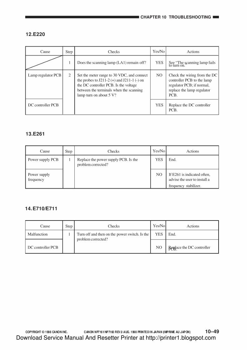
7/16/2019 Canon Np7161-Np7160 Copier Sm
http://slidepdf.com/reader/full/canon-np7161-np7160-copier-sm 279/345
COPYRIGHT © 1998 CANON INC. CANON NP7161/NP7160 REV.0 AUG. 1998 PRINTED IN JAPAN (IMPRIME AU JAPON)
CHAPTER 10 TROUBLESHOOTING
10–49
12.E220
Lamp regulator PCB
DC controller PCB
1
2
YES
NO
YES
Does the scanning lamp (LA1) remain off?
Set the meter range to 30 VDC, and connect
the probes to J211-2 (+) and J211-1 (-) on
the DC controller PCB. Is the voltage
between the terminals when the scanning
lamp turn on about 5 V?
See “The scanning lamp failsto turn on.”
Check the wiring from the DC
controller PCB to the lamp
regulator PCB; if normal,
replace the lamp regulator
PCB.
Replace the DC controller
PCB.
ActionsChecksStepCause Yes/No
13.E261
Power supply PCB
Power supply
frequency
1 YES
NO
Replace the power supply PCB. Is the
problem corrected?
End.
If E261 is indicated often,
advise the user to install a
frequency stabilizer.
ActionsChecksStepCause Yes/No
14.E710/E711
Malfunction
DC controller PCB
1 YES
NO
Turn off and then on the power switch. Is the
problem corrected?
End.
Replace the DC controllerPCB.
ActionsChecksStepCause Yes/No
Download Service Manual And Resetter Printer at http://printer1.blogspot.com
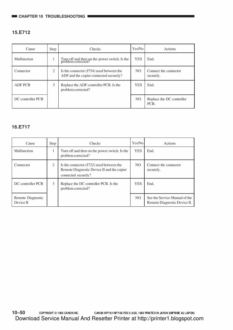
7/16/2019 Canon Np7161-Np7160 Copier Sm
http://slidepdf.com/reader/full/canon-np7161-np7160-copier-sm 280/345
CHAPTER 10 TROUBLESHOOTING
10–50 COPYRIGHT © 1998 CANON INC. CANON NP7161/NP7160 REV.0 AUG. 1998 PRINTED IN JAPAN (IMPRIME AU JAPON)
15.E712
Malfunction
Connector
ADF PCB
DC controller PCB
1
2
3
YES
NO
YES
NO
Turn off and then on the power switch. Is theproblem corrected?
Is the connector (J754) used between the
ADF and the copier connected securely?
Replace the ADF controller PCB. Is the
problem corrected?
End.
Connect the connector
securely.
End.
Replace the DC controller
PCB.
ActionsChecksStepCause Yes/No
16.E717
Malfunction
Connector
DC controller PCB
Remote Diagnostic
Device II
1
2
3
YES
NO
YES
NO
Turn off and then on the power switch. Is the
problem corrected?
Is the connector (J722) used between the
Remote Diagnostic Device II and the copier
connected securely?
Replace the DC controller PCB. Is the
problem corrected?
End.
Connect the connector
securely.
End.
See the Service Manual of the
Remote Diagnostic Device II.
ActionsChecksStepCause Yes/No
Download Service Manual And Resetter Printer at http://printer1.blogspot.com
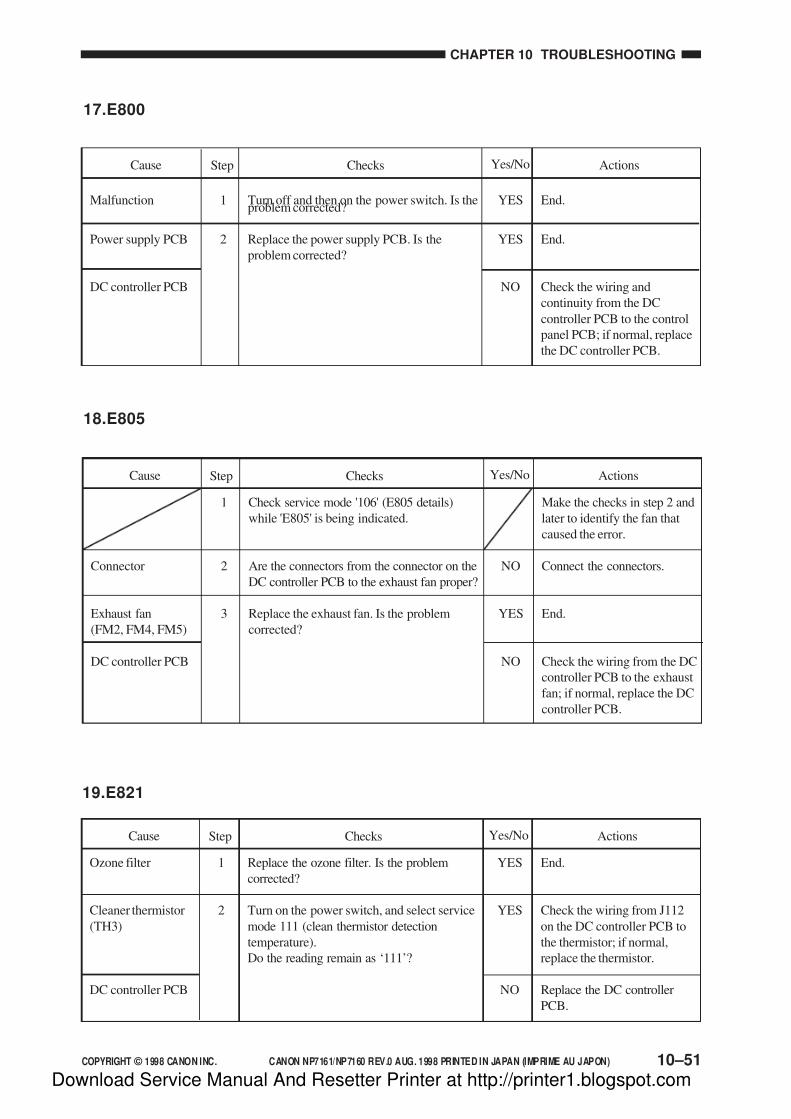
7/16/2019 Canon Np7161-Np7160 Copier Sm
http://slidepdf.com/reader/full/canon-np7161-np7160-copier-sm 281/345
COPYRIGHT © 1998 CANON INC. CANON NP7161/NP7160 REV.0 AUG. 1998 PRINTED IN JAPAN (IMPRIME AU JAPON)
CHAPTER 10 TROUBLESHOOTING
10–51
17.E800
Malfunction
Power supply PCB
DC controller PCB
1
2
YES
YES
NO
Turn off and then on the power switch. Is theproblem corrected?
Replace the power supply PCB. Is the
problem corrected?
End.
End.
Check the wiring and
continuity from the DC
controller PCB to the control
panel PCB; if normal, replace
the DC controller PCB.
ActionsChecksStepCause Yes/No
19.E821
ActionsChecksStepCause Yes/No
Ozone filter
Cleaner thermistor
(TH3)
DC controller PCB
YES
YES
NO
Replace the ozone filter. Is the problem
corrected?
Turn on the power switch, and select service
mode 111 (clean thermistor detection
temperature).
Do the reading remain as ‘111’?
End.
Check the wiring from J112
on the DC controller PCB to
the thermistor; if normal,
replace the thermistor.
Replace the DC controller
PCB.
1
2
Make the checks in step 2 and
later to identify the fan that
caused the error.
Connect the connectors.
End.
Check the wiring from the DC
controller PCB to the exhaust
fan; if normal, replace the DC
controller PCB.
18.E805
1
2
3
NO
YES
NO
ActionsChecksStepCause Yes/No
Check service mode '106' (E805 details)
while 'E805' is being indicated.
Are the connectors from the connector on the
DC controller PCB to the exhaust fan proper?
Replace the exhaust fan. Is the problem
corrected?
Connector
Exhaust fan
(FM2, FM4, FM5)
DC controller PCB
Download Service Manual And Resetter Printer at http://printer1.blogspot.com

7/16/2019 Canon Np7161-Np7160 Copier Sm
http://slidepdf.com/reader/full/canon-np7161-np7160-copier-sm 282/345
CHAPTER 10 TROUBLESHOOTING
10–52 COPYRIGHT © 1998 CANON INC. CANON NP7161/NP7160 REV.0 AUG. 1998 PRINTED IN JAPAN (IMPRIME AU JAPON)
20.AC power is absent.
1
2
3
4
5
6
7
8
9
10
11
12
NO
NO
NO
NO
YES
YES
YES
NO
YES
NO
NO
NO
YES
NO
Is the power cord connected to the copier?
Is the power plug connected to the power
outlet?
Is the rated AC voltage present at the power
outlet?
Is the front door closed securely?
Is the rated voltage present between J204-1
and J204-3 on the DC controller PCB?
Press the button on the circuit breaker (CB1,
CB2). Is AC power supplied?
Replace the power supply cord. Is AC power
supplied?
Is the fuse (FU1, FU2) on the DC power
supply PCB blown? (125 V, 5 A for 120 Vmodel; 250 V, 2 A for 230 V model)
Set the meter range to 30 VDC, and connect
the meter probes to J105-4(+) and J105-5(-)
on the DC controller PCB. Is the voltage
reading about 5 V?
Is there continuity between J101-B15 on the
DC controller PCB and J403-1 on the DC
controller PCB?
Is there continuity between J212-1 on the
DC power supply PCB and J106-2 on the
DC controller PCB?
Replace the control panel PCB. Is the
problem corrected?
Connect the cord.
Connect the power plug.
This is not the copier’s
problem. Inform the user
accordingly.
Close the front door.
End.
End.
End.
Check the wiring of the AC
power line. Check the
connector for contact.
Remove the cause, and replace
the fuse.
Check the wiring from J105
on the DC controller PCB to
the power supply PCB; if
normal, replace the power
supply PCB.
Check the wiring.
Check the wiring.
End.
Replace the DC power supply
PCB.
ActionsChecksStepCause Yes/No
Power cord
Power plug
Main power supply
Front door
Circuit breaker
(CB1, CB2)
Power cord
Fuse
Power supply PCB
Wiring
Control panel PCB
DC controller PCB
Download Service Manual And Resetter Printer at http://printer1.blogspot.com
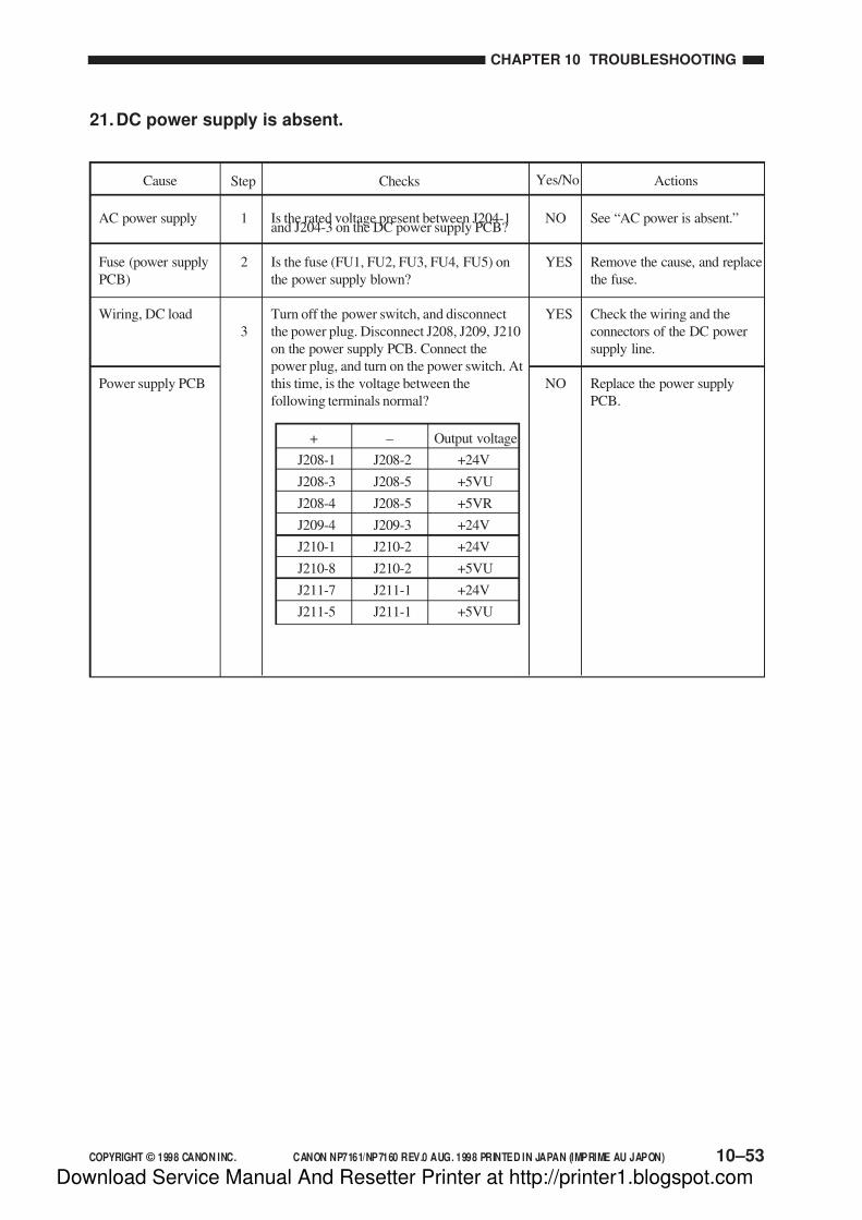
7/16/2019 Canon Np7161-Np7160 Copier Sm
http://slidepdf.com/reader/full/canon-np7161-np7160-copier-sm 283/345
COPYRIGHT © 1998 CANON INC. CANON NP7161/NP7160 REV.0 AUG. 1998 PRINTED IN JAPAN (IMPRIME AU JAPON)
CHAPTER 10 TROUBLESHOOTING
10–53
21.DC power supply is absent.
AC power supply
Fuse (power supply
PCB)
Wiring, DC load
Power supply PCB
1
2
3
NO
YES
YES
NO
Is the rated voltage present between J204-1and J204-3 on the DC power supply PCB?
Is the fuse (FU1, FU2, FU3, FU4, FU5) on
the power supply blown?
Turn off the power switch, and disconnect
the power plug. Disconnect J208, J209, J210
on the power supply PCB. Connect the
power plug, and turn on the power switch. At
this time, is the voltage between the
following terminals normal?
+ – Output voltage
J208-1 J208-2 +24V
J208-3 J208-5 +5VU
J208-4 J208-5 +5VR
J209-4 J209-3 +24V
J210-1 J210-2 +24V
J210-8 J210-2 +5VU
J211-7 J211-1 +24V
J211-5 J211-1 +5VU
See “AC power is absent.”
Remove the cause, and replace
the fuse.
Check the wiring and the
connectors of the DC power
supply line.
Replace the power supply
PCB.
ActionsChecksStepCause Yes/No
Download Service Manual And Resetter Printer at http://printer1.blogspot.com
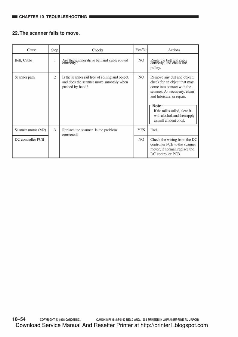
7/16/2019 Canon Np7161-Np7160 Copier Sm
http://slidepdf.com/reader/full/canon-np7161-np7160-copier-sm 284/345
CHAPTER 10 TROUBLESHOOTING
10–54 COPYRIGHT © 1998 CANON INC. CANON NP7161/NP7160 REV.0 AUG. 1998 PRINTED IN JAPAN (IMPRIME AU JAPON)
22.The scanner fails to move.
Belt, Cable
Scanner path
Scanner motor (M2)
DC controller PCB
1
2
3
NO
NO
YES
NO
Are the scanner drive belt and cable routedcorrectly?
Is the scanner rail free of soiling and object,
and does the scanner move smoothly when
pushed by hand?
Replace the scanner. Is the problem
corrected?
Route the belt and cablecorrectly, and check the
pulley.
Remove any dirt and object;
check for an object that may
come into contact with the
scanner. As necessary, clean
and lubricate, or repair.
Note:
If the rail is soiled, clean it
with alcohol, and then apply
a small amount of oil.
End.
Check the wiring from the DC
controller PCB to the scanner
motor; if normal, replace the
DC controller PCB.
ActionsChecksStepCause Yes/No
Download Service Manual And Resetter Printer at http://printer1.blogspot.com

7/16/2019 Canon Np7161-Np7160 Copier Sm
http://slidepdf.com/reader/full/canon-np7161-np7160-copier-sm 285/345
COPYRIGHT © 1998 CANON INC. CANON NP7161/NP7160 REV.0 AUG. 1998 PRINTED IN JAPAN (IMPRIME AU JAPON)
CHAPTER 10 TROUBLESHOOTING
10–55
Step Checks Actions
1
2
3
NO
NO
YES
NO
Cause
23.The lens fails to move.
Yes/No
Bolt
Lens path
Lens motor (M3)
DC controller PCB
Is the lens drive belt routed correctly?
Is the lens path free of dirt and foreign
object? Does the lens move smoothly when
pushed by hand?
Replace the lens motor. Is the problem
corrected?
Correct the belt, and check thegears.
Remove any dirt and object;
check for any object that may
come into contact with the
lens. As necessary, clean and
lubricate, or repair.
End.
Check the wiring from the DC
controller PCB to the lens
motor; if normal, replace the
DC controller PCB.
24.The mirror fails to move.
1
2
NO
YES
NO
Turn off the power, and move the mirror
assembly by hand. Does it move smoothly?
Replace the mirror motor. Is the problem
corrected?
Remove any dirt or foreign
object in the mirror path. As
necessary, clean and lubricate
the path.
End.
Check the wiring from the DC
controller PCB to the mirror
motor; if normal, replace the
DC controller PCB.
ActionsChecksStepCause Yes/No
Mirror path
Mirror motor (M4)
DC controller PCB
Download Service Manual And Resetter Printer at http://printer1.blogspot.com
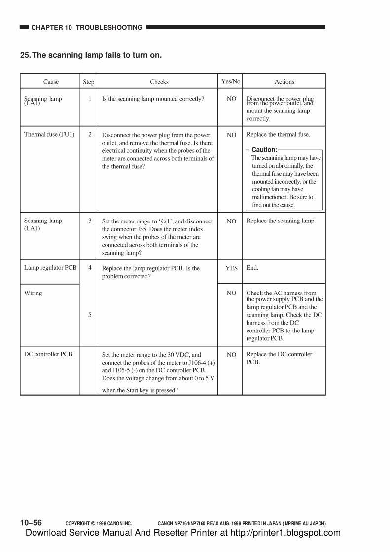
7/16/2019 Canon Np7161-Np7160 Copier Sm
http://slidepdf.com/reader/full/canon-np7161-np7160-copier-sm 286/345
CHAPTER 10 TROUBLESHOOTING
10–56 COPYRIGHT © 1998 CANON INC. CANON NP7161/NP7160 REV.0 AUG. 1998 PRINTED IN JAPAN (IMPRIME AU JAPON)
25.The scanning lamp fails to turn on.
1
2
3
4
5
NO
NO
NO
YES
NO
NO
Is the scanning lamp mounted correctly?
Disconnect the power plug from the power
outlet, and remove the thermal fuse. Is there
electrical continuity when the probes of the
meter are connected across both terminals of
the thermal fuse?
Set the meter range to ‘ýx1’, and disconnect
the connector J55. Does the meter index
swing when the probes of the meter are
connected across both terminals of the
scanning lamp?
Replace the lamp regulator PCB. Is the
problem corrected?
Set the meter range to the 30 VDC, and
connect the probes of the meter to J106-4 (+)
and J105-5 (-) on the DC controller PCB.
Does the voltage change from about 0 to 5 V
when the Start key is pressed?
Disconnect the power plugfrom the power outlet, and
mount the scanning lamp
correctly.
Replace the thermal fuse.
Caution:The scanning lamp may have
turned on abnormally, the
thermal fuse may have been
mounted incorrectly, or the
cooling fan may have
malfunctioned. Be sure to
find out the cause.
Replace the scanning lamp.
End.
Check the AC harness fromthe power supply PCB and the
lamp regulator PCB and the
scanning lamp. Check the DC
harness from the DC
controller PCB to the lamp
regulator PCB.
Replace the DC controller
PCB.
Scanning lamp(LA1)
Thermal fuse (FU1)
Scanning lamp
(LA1)
Lamp regulator PCB
Wiring
DC controller PCB
ActionsChecksStepCause Yes/No
Download Service Manual And Resetter Printer at http://printer1.blogspot.com
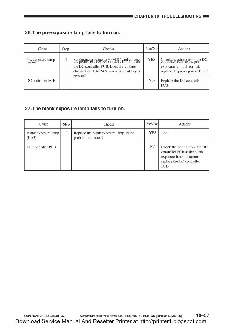
7/16/2019 Canon Np7161-Np7160 Copier Sm
http://slidepdf.com/reader/full/canon-np7161-np7160-copier-sm 287/345
COPYRIGHT © 1998 CANON INC. CANON NP7161/NP7160 REV.0 AUG. 1998 PRINTED IN JAPAN (IMPRIME AU JAPON)
CHAPTER 10 TROUBLESHOOTING
10–57
26.The pre-exposure lamp fails to turn on.
Pre-exposure lamp(LA2)
DC controller PCB
1 YES
NO
Set the meter range to 30 VDC, and connectthe probes to J104-A6 (+) and J104-7 (-) on
the DC controller PCB. Does the voltage
change from 0 to 24 V when the Start key is
pressed?
Check the wiring from the DCcontroller PCB to the pre-
exposure lamp; if normal,
replace the pre-exposure lamp.
Replace the DC controller
PCB.
ActionsChecksStepCause Yes/No
1 YES
NO
27.The blank exposure lamp fails to turn on.
ActionsChecksStepCause Yes/No
Blank exposure lamp
(LA3)
DC controller PCB
Replace the blank exposure lamp. Is the
problem corrected?
End.
Check the wiring from the DC
controller PCB to the blank
exposure lamp; if normal,
replace the DC controller
PCB.
Download Service Manual And Resetter Printer at http://printer1.blogspot.com
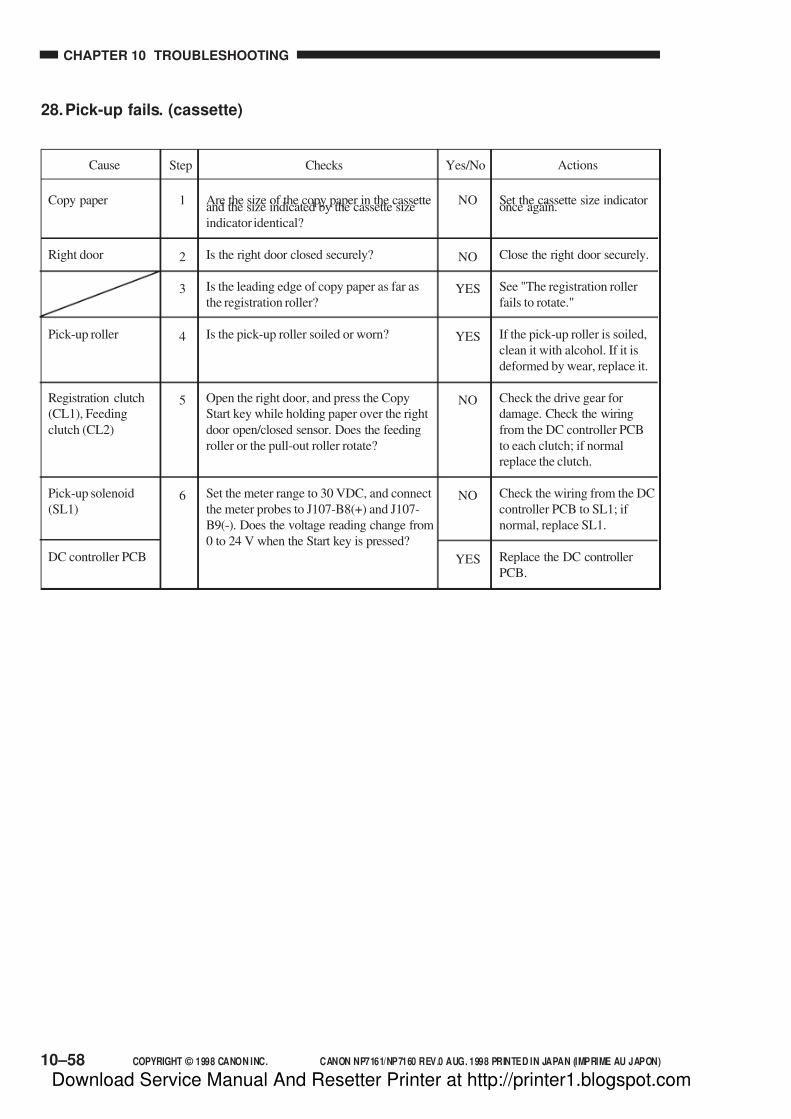
7/16/2019 Canon Np7161-Np7160 Copier Sm
http://slidepdf.com/reader/full/canon-np7161-np7160-copier-sm 288/345
CHAPTER 10 TROUBLESHOOTING
10–58 COPYRIGHT © 1998 CANON INC. CANON NP7161/NP7160 REV.0 AUG. 1998 PRINTED IN JAPAN (IMPRIME AU JAPON)
28.Pick-up fails. (cassette)
1
2
3
4
5
6
NO
NO
YES
YES
NO
NO
YES
ActionsChecksStepCause Yes/No
Copy paper
Right door
Pick-up roller
Registration clutch
(CL1), Feeding
clutch (CL2)
Pick-up solenoid
(SL1)
DC controller PCB
Are the size of the copy paper in the cassetteand the size indicated by the cassette size
indicator identical?
Is the right door closed securely?
Is the leading edge of copy paper as far as
the registration roller?
Is the pick-up roller soiled or worn?
Open the right door, and press the Copy
Start key while holding paper over the right
door open/closed sensor. Does the feeding
roller or the pull-out roller rotate?
Set the meter range to 30 VDC, and connect
the meter probes to J107-B8(+) and J107-
B9(-). Does the voltage reading change from
0 to 24 V when the Start key is pressed?
Set the cassette size indicatoronce again.
Close the right door securely.
See "The registration roller
fails to rotate."
If the pick-up roller is soiled,
clean it with alcohol. If it is
deformed by wear, replace it.
Check the drive gear for
damage. Check the wiring
from the DC controller PCB
to each clutch; if normal
replace the clutch.
Check the wiring from the DC
controller PCB to SL1; if
normal, replace SL1.
Replace the DC controller
PCB.
Download Service Manual And Resetter Printer at http://printer1.blogspot.com
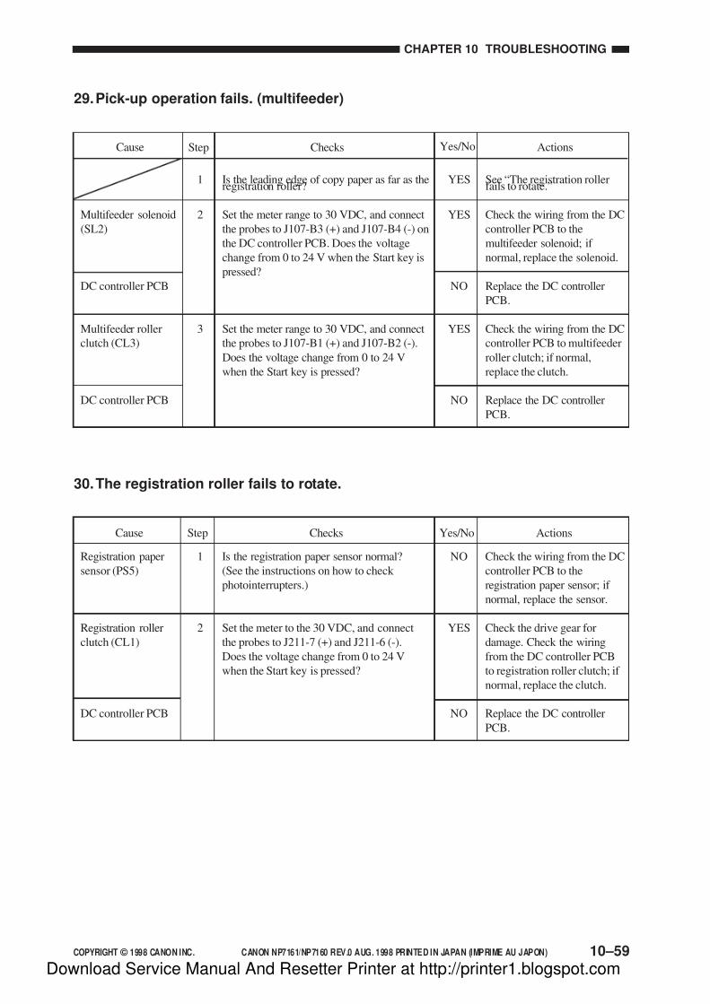
7/16/2019 Canon Np7161-Np7160 Copier Sm
http://slidepdf.com/reader/full/canon-np7161-np7160-copier-sm 289/345
COPYRIGHT © 1998 CANON INC. CANON NP7161/NP7160 REV.0 AUG. 1998 PRINTED IN JAPAN (IMPRIME AU JAPON)
CHAPTER 10 TROUBLESHOOTING
10–59
YES
YES
NO
YES
NO
Yes/No
29.Pick-up operation fails. (multifeeder)
Multifeeder solenoid
(SL2)
DC controller PCB
Multifeeder roller
clutch (CL3)
DC controller PCB
1
2
3
Is the leading edge of copy paper as far as theregistration roller?
Set the meter range to 30 VDC, and connect
the probes to J107-B3 (+) and J107-B4 (-) on
the DC controller PCB. Does the voltage
change from 0 to 24 V when the Start key is
pressed?
Set the meter range to 30 VDC, and connect
the probes to J107-B1 (+) and J107-B2 (-).
Does the voltage change from 0 to 24 V
when the Start key is pressed?
ActionsChecksStepCause
See “The registration rollerfails to rotate.”
Check the wiring from the DC
controller PCB to the
multifeeder solenoid; if
normal, replace the solenoid.
Replace the DC controller
PCB.
Check the wiring from the DC
controller PCB to multifeeder
roller clutch; if normal,
replace the clutch.
Replace the DC controller
PCB.
30.The registration roller fails to rotate.
Registration paper
sensor (PS5)
Registration roller
clutch (CL1)
DC controller PCB
1
2
Is the registration paper sensor normal?
(See the instructions on how to check
photointerrupters.)
Set the meter to the 30 VDC, and connect
the probes to J211-7 (+) and J211-6 (-).
Does the voltage change from 0 to 24 V
when the Start key is pressed?
Check the wiring from the DC
controller PCB to the
registration paper sensor; if
normal, replace the sensor.
Check the drive gear for
damage. Check the wiring
from the DC controller PCB
to registration roller clutch; if
normal, replace the clutch.
Replace the DC controller
PCB.
ActionsChecksStepCause
NO
YES
NO
Yes/No
Download Service Manual And Resetter Printer at http://printer1.blogspot.com

7/16/2019 Canon Np7161-Np7160 Copier Sm
http://slidepdf.com/reader/full/canon-np7161-np7160-copier-sm 290/345
CHAPTER 10 TROUBLESHOOTING
10–60 COPYRIGHT © 1998 CANON INC. CANON NP7161/NP7160 REV.0 AUG. 1998 PRINTED IN JAPAN (IMPRIME AU JAPON)
31.The fixing heater fails to turn on.
Thermal switch(TSW1)
Fixing heater (H1)
DC controller PCB
Wiring
1
2
3
NO
NO
NO
YES
Turn off the power switch, and remove thefixing assembly. Set the meter range to
“Ωx1.” Does the meter index swing when
the probes are connected across both
terminals of the thermal switch?
Turn off the power switch, and remove the
fixing assembly. Is there continuity when
probes are connected across both terminals
of the fixing heater?
Set the meter range to 30 VDC, and connect
the probes to J106-21 (+) and J105-4 (-) on
the DC controller PCB. Is the resistance
about 5 V?
Replace the thermal switch.
Replace the fixing heater.
Replace the DC controller
PCB.
Check the AC harness from
the DC power supply PCB to
the fixing heater. Check the
DC harness from the DC
controller PCB to the DC
power supply PCB.
ActionsChecksStepCause Yes/No
32.The Add Toner indicator does not flash/turn on.
Connector
Toner sensor (TS1)
Control panel PCB
DC controller PCB
1
2
3
NO
YES
NO
YES
Connect the connectors
securely.
End.
Check the wiring from the DCcontroller PC to the control
panel PCB; if normal, replace
the control panel PCB.
Replace the DC controller
PCB.
Are the connector J15 of the toner sensor,
relay connectors J721 and J722, and the
connector J102 on the DC controller PCB
connected securely?
Replace the toner sensor. Is the problem
corrected?
Execute service mode ‘409’ (control panelcheck). Does the Add Toner indicator turn
on?
ActionsChecksStepCause Yes/No
Download Service Manual And Resetter Printer at http://printer1.blogspot.com
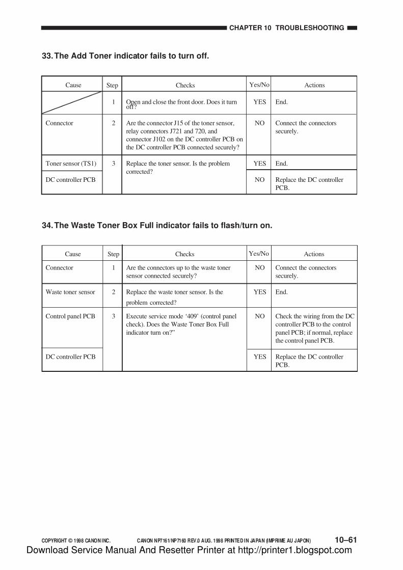
7/16/2019 Canon Np7161-Np7160 Copier Sm
http://slidepdf.com/reader/full/canon-np7161-np7160-copier-sm 291/345
COPYRIGHT © 1998 CANON INC. CANON NP7161/NP7160 REV.0 AUG. 1998 PRINTED IN JAPAN (IMPRIME AU JAPON)
CHAPTER 10 TROUBLESHOOTING
10–61
33.The Add Toner indicator fails to turn off.
Connector
Toner sensor (TS1)
DC controller PCB
1
2
3
YES
NO
YES
NO
Open and close the front door. Does it turnoff?
Are the connector J15 of the toner sensor,
relay connectors J721 and 720, and
connector J102 on the DC controller PCB on
the DC controller PCB connected securely?
Replace the toner sensor. Is the problem
corrected?
End.
Connect the connectors
securely.
End.
Replace the DC controller
PCB.
ActionsChecksStepCause Yes/No
34.The Waste Toner Box Full indicator fails to flash/turn on.
Connector
Waste toner sensor
Control panel PCB
DC controller PCB
1
2
3
NO
YES
NO
YES
Are the connectors up to the waste toner
sensor connected securely?
Replace the waste toner sensor. Is the
problem corrected?
Execute service mode ‘409’ (control panel
check). Does the Waste Toner Box Full
indicator turn on?”
Connect the connectors
securely.
End.
Check the wiring from the DC
controller PCB to the control
panel PCB; if normal, replace
the control panel PCB.
Replace the DC controller
PCB.
ActionsChecksCause Yes/NoStep
Download Service Manual And Resetter Printer at http://printer1.blogspot.com
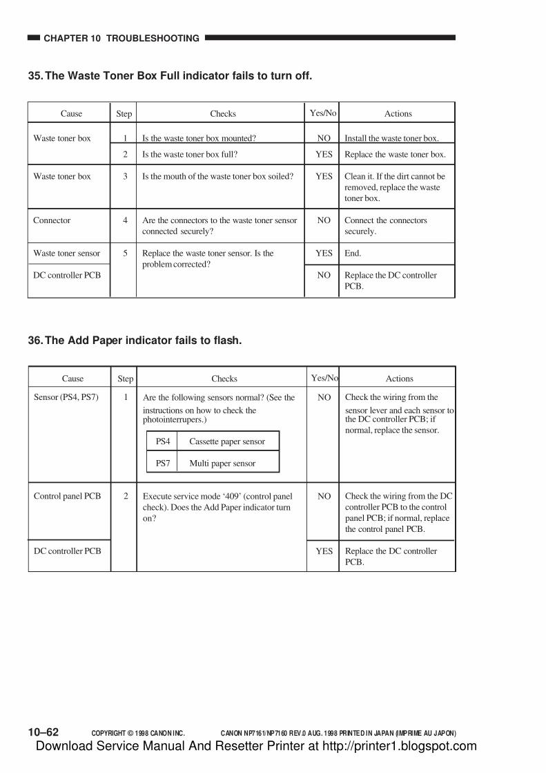
7/16/2019 Canon Np7161-Np7160 Copier Sm
http://slidepdf.com/reader/full/canon-np7161-np7160-copier-sm 292/345
CHAPTER 10 TROUBLESHOOTING
10–62 COPYRIGHT © 1998 CANON INC. CANON NP7161/NP7160 REV.0 AUG. 1998 PRINTED IN JAPAN (IMPRIME AU JAPON)
35.The Waste Toner Box Full indicator fails to turn off.
Waste toner box
Waste toner box
Connector
Waste toner sensor
DC controller PCB
1
2
3
4
5
NO
YES
YES
NO
YES
NO
Is the waste toner box mounted?
Is the waste toner box full?
Is the mouth of the waste toner box soiled?
Are the connectors to the waste toner sensor
connected securely?
Replace the waste toner sensor. Is the
problem corrected?
Install the waste toner box.
Replace the waste toner box.
Clean it. If the dirt cannot be
removed, replace the waste
toner box.
Connect the connectors
securely.
End.
Replace the DC controller
PCB.
ActionsChecksStepCause Yes/No
36.The Add Paper indicator fails to flash.
Sensor (PS4, PS7)
Control panel PCB
DC controller PCB
1
2
NO
NO
YES
Are the following sensors normal? (See the
instructions on how to check thephotointerrupers.)
PS4 Cassette paper sensor
PS7 Multi paper sensor
Execute service mode ‘409’ (control panel
check). Does the Add Paper indicator turn
on?
Check the wiring from the
sensor lever and each sensor tothe DC controller PCB; if
normal, replace the sensor.
Check the wiring from the DC
controller PCB to the control
panel PCB; if normal, replace
the control panel PCB.
Replace the DC controller
PCB.
ActionsChecksStepCause Yes/No
Download Service Manual And Resetter Printer at http://printer1.blogspot.com

7/16/2019 Canon Np7161-Np7160 Copier Sm
http://slidepdf.com/reader/full/canon-np7161-np7160-copier-sm 293/345
COPYRIGHT © 1998 CANON INC. CANON NP7161/NP7160 REV.0 AUG. 1998 PRINTED IN JAPAN (IMPRIME AU JAPON)
CHAPTER 10 TROUBLESHOOTING
10–63
37.The Add Paper indicator fails to turn off.
Cassette
Sensor (PS4, PS7)
DC controller PCB
1
2
NO
NO
YES
Is the cassette set correctly?
Are the following sensors normal? (See the
instructions on how to check the
photointerrupers.)
PS4 Cassette paper sensor
PS7 Multi paper sensor
Set the cassette correctly.
Check the wiring from the
sensor lever and each sensor to
the DC controller PCB; if
normal, replace the sensor.
Replace the DC controller.
ActionsChecksStepCause Yes/No
38.The Jam indicator fails to flash.
Sensor (PSS5, PS6)
Control panel PCB
DC controller PCB
1
2
NO
NO
YES
Are the following sensors normal? (See the
instruction on how to check the
photointerrupters.)
PS5 Registration paper sensor
PS6 Delivery paper sensor
Execute service mode ‘409’ (control panel
check). Does the Jam indicator turn on?
Check the wiring from the
sensor lever and each sensor to
the DC controller PCB; if
normal, replace the sensor.
Check the wiring from the DC
controller PCB to the control
panel PCB; if normal, replace
the control panel PCB.
Replace the DC controller
PCB.
ActionsChecksStepCause Yes/No
Download Service Manual And Resetter Printer at http://printer1.blogspot.com
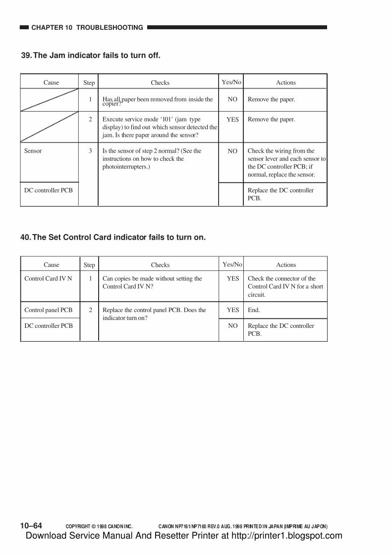
7/16/2019 Canon Np7161-Np7160 Copier Sm
http://slidepdf.com/reader/full/canon-np7161-np7160-copier-sm 294/345
CHAPTER 10 TROUBLESHOOTING
10–64 COPYRIGHT © 1998 CANON INC. CANON NP7161/NP7160 REV.0 AUG. 1998 PRINTED IN JAPAN (IMPRIME AU JAPON)
39.The Jam indicator fails to turn off.
Sensor
DC controller PCB
1
2
3
NO
YES
NO
Has all paper been removed from inside thecopier?
Execute service mode ‘101’ (jam type
display) to find out which sensor detected the
jam. Is there paper around the sensor?
Is the sensor of step 2 normal? (See the
instructions on how to check the
photointerrupters.)
Remove the paper.
Remove the paper.
Check the wiring from the
sensor lever and each sensor to
the DC controller PCB; if
normal, replace the sensor.
Replace the DC controller
PCB.
ActionsChecksStepCause Yes/No
40.The Set Control Card indicator fails to turn on.
Control Card IV N
Control panel PCB
DC controller PCB
1
2
YES
YES
NO
Can copies be made without setting the
Control Card IV N?
Replace the control panel PCB. Does the
indicator turn on?
Check the connector of the
Control Card IV N for a short
circuit.
End.
Replace the DC controller
PCB.
ActionsChecksStepCause Yes/No
Download Service Manual And Resetter Printer at http://printer1.blogspot.com

7/16/2019 Canon Np7161-Np7160 Copier Sm
http://slidepdf.com/reader/full/canon-np7161-np7160-copier-sm 295/345
COPYRIGHT © 1998 CANON INC. CANON NP7161/NP7160 REV.0 AUG. 1998 PRINTED IN JAPAN (IMPRIME AU JAPON)
CHAPTER 10 TROUBLESHOOTING
10–65
41.The Set Control Card indicator fails to turn off.
Control card
DC controller PCB
Control Card IV N
1
2
YES
YES
NO
Is the Control Card set correctly?
Can copies be made?
Set the control card correctly.
Replace the DC controller
PCB.
Replace the Control Card IV
N.
ActionsChecksStepCause Yes/No
Download Service Manual And Resetter Printer at http://printer1.blogspot.com

7/16/2019 Canon Np7161-Np7160 Copier Sm
http://slidepdf.com/reader/full/canon-np7161-np7160-copier-sm 296/345
CHAPTER 10 TROUBLESHOOTING
10–66 COPYRIGHT © 1998 CANON INC. CANON NP7161/NP7160 REV.0 AUG. 1998 PRINTED IN JAPAN (IMPRIME AU JAPON)
V. TROUBLESHOOTING FEEDING PROBLEMS
A. Copy Jams
The copier may be divided into the following in terms of where copy paper tends to jam.[1] Pick-up/feeding assembly
[2] Fixing/delivery assembly
The instructions on how to remove copy paper in the following tables are organized
according to location.
You may find out the location and the nature of each jam in service mode (‘107’).
[2] [1]
Figure 10-501
Download Service Manual And Resetter Printer at http://printer1.blogspot.com
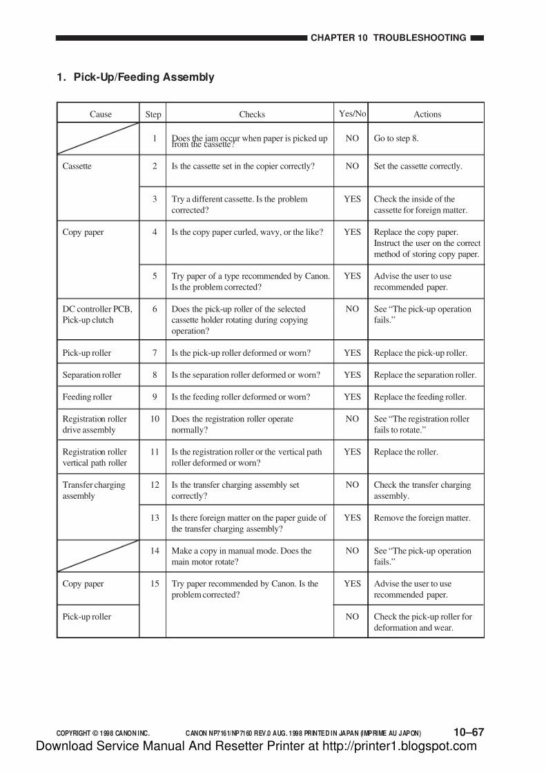
7/16/2019 Canon Np7161-Np7160 Copier Sm
http://slidepdf.com/reader/full/canon-np7161-np7160-copier-sm 297/345
COPYRIGHT © 1998 CANON INC. CANON NP7161/NP7160 REV.0 AUG. 1998 PRINTED IN JAPAN (IMPRIME AU JAPON)
CHAPTER 10 TROUBLESHOOTING
10–67
1. Pick-Up/Feeding Assembly
1
2
3
4
5
6
7
8
9
10
11
12
13
14
15
NO
NO
YES
YES
YES
NO
YES
YES
YES
NO
YES
NO
YES
NO
YES
NO
Does the jam occur when paper is picked upfrom the cassette?
Is the cassette set in the copier correctly?
Try a different cassette. Is the problem
corrected?
Is the copy paper curled, wavy, or the like?
Try paper of a type recommended by Canon.
Is the problem corrected?
Does the pick-up roller of the selected
cassette holder rotating during copying
operation?
Is the pick-up roller deformed or worn?
Is the separation roller deformed or worn?
Is the feeding roller deformed or worn?
Does the registration roller operate
normally?
Is the registration roller or the vertical path
roller deformed or worn?
Is the transfer charging assembly set
correctly?
Is there foreign matter on the paper guide of
the transfer charging assembly?
Make a copy in manual mode. Does the
main motor rotate?
Try paper recommended by Canon. Is the
problem corrected?
Go to step 8.
Set the cassette correctly.
Check the inside of the
cassette for foreign matter.
Replace the copy paper.
Instruct the user on the correct
method of storing copy paper.
Advise the user to use
recommended paper.
See “The pick-up operation
fails.”
Replace the pick-up roller.
Replace the separation roller.
Replace the feeding roller.
See “The registration roller
fails to rotate.”
Replace the roller.
Check the transfer charging
assembly.
Remove the foreign matter.
See “The pick-up operation
fails.”
Advise the user to use
recommended paper.
Check the pick-up roller for
deformation and wear.
Cassette
Copy paper
DC controller PCB,
Pick-up clutch
Pick-up roller
Separation roller
Feeding roller
Registration roller
drive assembly
Registration roller
vertical path roller
Transfer charging
assembly
Copy paper
Pick-up roller
ActionsChecksStepCause Yes/No
Download Service Manual And Resetter Printer at http://printer1.blogspot.com

7/16/2019 Canon Np7161-Np7160 Copier Sm
http://slidepdf.com/reader/full/canon-np7161-np7160-copier-sm 298/345
CHAPTER 10 TROUBLESHOOTING
10–68 COPYRIGHT © 1998 CANON INC. CANON NP7161/NP7160 REV.0 AUG. 1998 PRINTED IN JAPAN (IMPRIME AU JAPON)
2. Fixing/Delivery Assembly
Cause Step Checks Actions
Separation claw(delivery assembly)
1
2
3
4
5
6
7
8
YES
YES
YES
NO
YES
NO
NO
NO
YES
1. Replace the separationclaw.
2. If dirt is found, clean it.
Replace the roller.
Clean the paper guide.
Adjust the height.
Adjust it.
Adjust the lever so that it
moves smoothly.
Replace the sensor.
Check the delivery roller driveassembly.
Check the copy to see if it has
a leading edge.
Yes/No
Upper/lower
fixing roller,
Heat
discharging
roller
Paper guide
Nip
Delivery lever
Delivery paper
sensor
(PS06)
Delivery rollerdrive assembly
Is the separation claw worn, deformed, orsoiled?
Is the upper/lower fixing roller or the heat
discharging roller deformed or damaged?
Is the paper guide soiled with toner or the
like?
Is the height of the paper guide correct?
Is the lower roller pressure (nip) as
indicated?
Does the delivery detecting lever move
smoothly?
Does the delivery sensor operate normally?
(See the instructions on how to check the
photointerrupters.)
Does the delivery roller move smoothly?
Leading edge
margin
F i x i n g a s s e m b l y
D e l i v e r y a s s e m b l y
Download Service Manual And Resetter Printer at http://printer1.blogspot.com
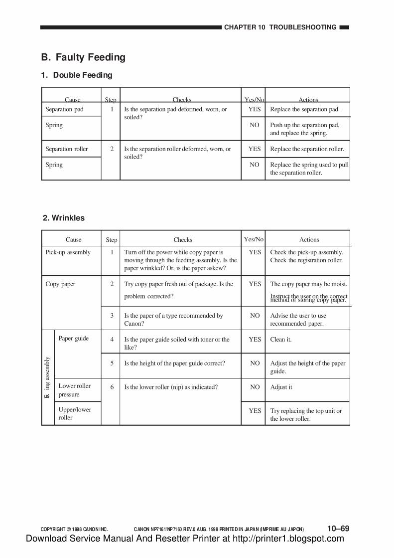
7/16/2019 Canon Np7161-Np7160 Copier Sm
http://slidepdf.com/reader/full/canon-np7161-np7160-copier-sm 299/345
COPYRIGHT © 1998 CANON INC. CANON NP7161/NP7160 REV.0 AUG. 1998 PRINTED IN JAPAN (IMPRIME AU JAPON)
CHAPTER 10 TROUBLESHOOTING
10–69
B. Faulty Feeding
1. Double Feeding
1
2
YES
NO
YES
NO
Is the separation pad deformed, worn, or
soiled?
Is the separation roller deformed, worn, or
soiled?
Replace the separation pad.
Push up the separation pad,
and replace the spring.
Replace the separation roller.
Replace the spring used to pull
the separation roller.
Cause ActionsChecksStep Yes/No
Separation pad
Spring
Separation roller
Spring
2. Wrinkles
Pick-up assembly
Copy paper
1
2
3
4
5
6
YES
YES
NO
YES
NO
NO
YES
Turn off the power while copy paper is
moving through the feeding assembly. Is the
paper wrinkled? Or, is the paper askew?
Try copy paper fresh out of package. Is the
problem corrected?
Is the paper of a type recommended by
Canon?
Is the paper guide soiled with toner or the
like?
Is the height of the paper guide correct?
Is the lower roller (nip) as indicated?
Check the pick-up assembly.
Check the registration roller.
The copy paper may be moist.
Instruct the user on the correctmethod of storing copy paper.
Advise the user to use
recommended paper.
Clean it.
Adjust the height of the paper
guide.
Adjust it
Try replacing the top unit or
the lower roller.
Cause ActionsChecksStep
Paper guide
Lower roller
pressure
Upper/lower
roller
F i x
i n g a s s e m b l y
Yes/No
Download Service Manual And Resetter Printer at http://printer1.blogspot.com

7/16/2019 Canon Np7161-Np7160 Copier Sm
http://slidepdf.com/reader/full/canon-np7161-np7160-copier-sm 300/345
CHAPTER 10 TROUBLESHOOTING
10–70 COPYRIGHT © 1998 CANON INC. CANON NP7161/NP7160 REV.0 AUG. 1998 PRINTED IN JAPAN (IMPRIME AU JAPON)
VI. ARRANGEMENT AND FUNCTIONS OFELECTRICAL PARTS
A. Sensors and Switches
Figure 10-601
PS11
PS7
PS4
PS5
PS6
PS9
PS10
TS1
PS1
DS1
SW1
PS8
PS2
PS3
Download Service Manual And Resetter Printer at http://printer1.blogspot.com

7/16/2019 Canon Np7161-Np7160 Copier Sm
http://slidepdf.com/reader/full/canon-np7161-np7160-copier-sm 301/345
COPYRIGHT © 1998 CANON INC. CANON NP7161/NP7160 REV.0 AUG. 1998 PRINTED IN JAPAN (IMPRIME AU JAPON) 10–71
CHAPTER 10 TROUBLESHOOTING
Symbol Name Notation Description
Toner sensor
Photointerrupter
Switch
TS1
PS1
PS2
PS3
PS4
PS5
PS6
PS7
PS8
PS9
PS10
PS11
SW1
DS1
Developing assembly toner level detection
Scanner home position detection
Lens home position detection
Mirror home position detection
Cassette paper detection
Registration paper detection
Delivery detection
Multifeeder paper detection
Waste toner feeding screw locked detection
Multifeeder paper width detection 1
Multifeeder paper width detection 2
Right door open/closed detection
Heater switch (accessory)
Front door switch
Table 10-601
Download Service Manual And Resetter Printer at http://printer1.blogspot.com

7/16/2019 Canon Np7161-Np7160 Copier Sm
http://slidepdf.com/reader/full/canon-np7161-np7160-copier-sm 302/345
CHAPTER 10 TROUBLESHOOTING
10–72 COPYRIGHT © 1998 CANON INC. CANON NP7161/NP7160 REV.0 AUG. 1998 PRINTED IN JAPAN (IMPRIME AU JAPON)
Figure 10-602
B. Motors, Fans, Clutches, and Solenoids
SL2
SL1
CL3CL2
M4
M2
M1
CL1
FM1FM2
FM4 FM5
M3
Download Service Manual And Resetter Printer at http://printer1.blogspot.com

7/16/2019 Canon Np7161-Np7160 Copier Sm
http://slidepdf.com/reader/full/canon-np7161-np7160-copier-sm 303/345
COPYRIGHT © 1998 CANON INC. CANON NP7161/NP7160 REV.0 AUG. 1998 PRINTED IN JAPAN (IMPRIME AU JAPON) 10–73
CHAPTER 10 TROUBLESHOOTING
Symbol Name Notation Description
Motor
Fan
Clutch
Solenoid
M1
M2
M3
M4
FM1
FM2
FM4
FM5
CL1
CL2
CL3
SL1
SL2
Main drive
Scanner drive
Lens drive
No. 4/No. 5 mirror drive
Cooling
Heat discharge
Heat discharge
Heat discharge (accessory)
Registration roller clutch
Feeding clutch
Multifeeder pick-up clutch
Pick-up solenoid
Multifeeder pick-up solenoid
M
SL
CL
Table 10-602
Download Service Manual And Resetter Printer at http://printer1.blogspot.com

7/16/2019 Canon Np7161-Np7160 Copier Sm
http://slidepdf.com/reader/full/canon-np7161-np7160-copier-sm 304/345
CHAPTER 10 TROUBLESHOOTING
10–74 COPYRIGHT © 1998 CANON INC. CANON NP7161/NP7160 REV.0 AUG. 1998 PRINTED IN JAPAN (IMPRIME AU JAPON)
Figure 10-603
C. Heaters, Lamps, and Others
RL1
TH3
TH2
TH1
TP1VZ1
H1
H2
H3
LA3
LA2
LA1
FU1
CNT1
CNT2
Download Service Manual And Resetter Printer at http://printer1.blogspot.com
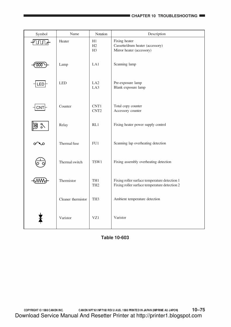
7/16/2019 Canon Np7161-Np7160 Copier Sm
http://slidepdf.com/reader/full/canon-np7161-np7160-copier-sm 305/345
COPYRIGHT © 1998 CANON INC. CANON NP7161/NP7160 REV.0 AUG. 1998 PRINTED IN JAPAN (IMPRIME AU JAPON) 10–75
CHAPTER 10 TROUBLESHOOTING
Symbol Name Notation Description
H1
H2
H3
LA1
LA2
LA3
CNT1
CNT2
RL1
FU1
TSW1
TH1
TH2
TH3
VZ1
Fixing heater
Cassette/drum heater (accessory)
Mirror heater (accessory)
Scanning lamp
Pre-exposure lamp
Blank exposure lamp
Total copy counter
Accessory counter
Fixing heater power supply control
Scanning lap overheating detection
Fixing assembly overheating detection
Fixing roller surface temperature detection 1
Fixing roller surface temperature detection 2
Ambient temperature detection
Varistor
Heater
Lamp
LED
Counter
Relay
Thermal fuse
Thermal switch
Thermistor
Cleaner thermistor
Varistor
LED
CNT
Table 10-603
Download Service Manual And Resetter Printer at http://printer1.blogspot.com
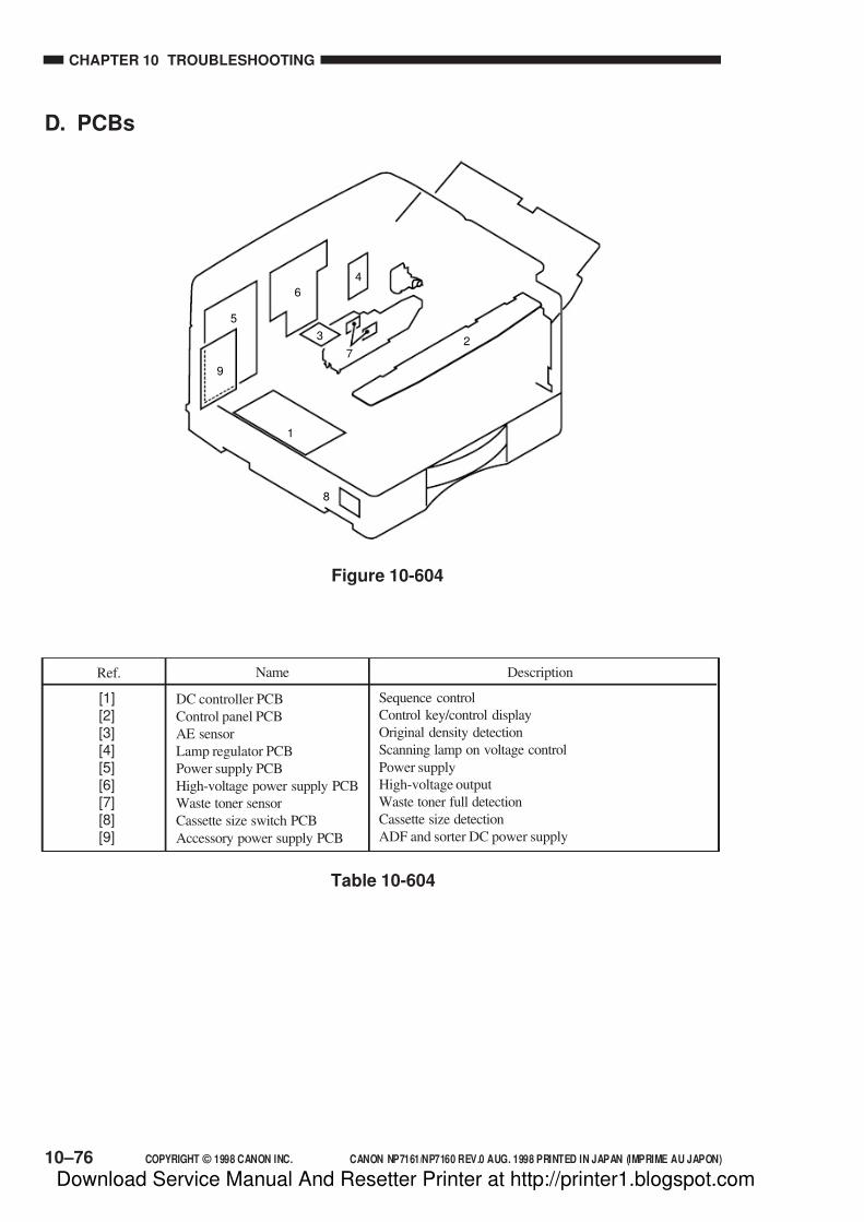
7/16/2019 Canon Np7161-Np7160 Copier Sm
http://slidepdf.com/reader/full/canon-np7161-np7160-copier-sm 306/345
CHAPTER 10 TROUBLESHOOTING
10–76 COPYRIGHT © 1998 CANON INC. CANON NP7161/NP7160 REV.0 AUG. 1998 PRINTED IN JAPAN (IMPRIME AU JAPON)
D. PCBs
4
6
5
9
1
8
27
3
Figure 10-604
Ref. Description
Sequence control
Control key/control display
Original density detection
Scanning lamp on voltage control
Power supply
High-voltage output
Waste toner full detection
Cassette size detection
ADF and sorter DC power supply
Name
DC controller PCB
Control panel PCB
AE sensor
Lamp regulator PCB
Power supply PCB
High-voltage power supply PCB
Waste toner sensor
Cassette size switch PCB
Accessory power supply PCB
[1][2][3][4][5][6][7][8][9]
Table 10-604
Download Service Manual And Resetter Printer at http://printer1.blogspot.com

7/16/2019 Canon Np7161-Np7160 Copier Sm
http://slidepdf.com/reader/full/canon-np7161-np7160-copier-sm 307/345
COPYRIGHT © 1998 CANON INC. CANON NP7161/NP7160 REV.0 AUG. 1998 PRINTED IN JAPAN (IMPRIME AU JAPON) 10–77
CHAPTER 10 TROUBLESHOOTING
E. Variable Resistors, Light-Emitting Diodes, and Check Pins byPCB
Of the variable resistors (VR), light-emitting diodes (LD), and check pins used in the copier,
those needed for servicing work in the field are discussed.
Caution:
1.Some LEDs retain current even when off and emit dim light. This is a normal condition
and must be kept in mind.
2.VRs that may be used in the field .....................................................
3.VRs that must not be used in the field ..............................................
Caution:
Do not use the VRs or check pins not found in the tables. They are for factory use, and
require special tools and high accuracy.
1. DC Controller PCB
Figure 10-605
J109
J106
J101
B1B15
1
3
5
1
J1081
4
A15A1
J104
B1B12
A12A1
J102
B1B13
A13A1
J112
2 1
J120
8 1
J103
B1B9
A9A1
J107
B15A1
B1A15
J122
A1A16
B16B1
J121
81
SW102 J131
15
J105
51
J1105
1
J1243
1
Download Service Manual And Resetter Printer at http://printer1.blogspot.com

7/16/2019 Canon Np7161-Np7160 Copier Sm
http://slidepdf.com/reader/full/canon-np7161-np7160-copier-sm 308/345
CHAPTER 10 TROUBLESHOOTING
10–78 COPYRIGHT © 1998 CANON INC. CANON NP7161/NP7160 REV.0 AUG. 1998 PRINTED IN JAPAN (IMPRIME AU JAPON)
A-configuration (2R2E) Ratio
200%
A4→A3
A3→A4
50%
200.0%
141.4%
100% 100.0%
70.7%
50.0%
Inch-configuration (4R3E) Ratio
200%LTR→11"×17"
LGL→11"×17"
100%
LGL→LTR
11"×17"→LGL
11"×17"→LTR
50%
200.0%129.4%
121.4%
100.0%
78.6%
73.3%
64.7%
50.0%
Table 10-606
Table 10-607
Item Remarks
Settings
SW102-1
SW102-2
SW102-3
SW102-4
SW102-5
SW102-6
SW102-7
SW102-8
Use to change size.
Use to set power supply voltage.
—
—
—
—
Use to set the accessorycounter.
Large size copy counting method
INCH
A
AB/INCH
AB
SW102-1
ON
OFF
ON
ON :230V OFF : 120V
ON: 2 counts OFF: 1 count
OFF
SW102-2
ON
ON
OFF
OFF
Settings
No accessory counter
Small-size copy counter
Large-size copy counter
Not used
SW102-5
OFF
ON
OFF
ON
SW102-6
OFF
OFF
ON
ON
Table 10-605
Download Service Manual And Resetter Printer at http://printer1.blogspot.com

7/16/2019 Canon Np7161-Np7160 Copier Sm
http://slidepdf.com/reader/full/canon-np7161-np7160-copier-sm 309/345
COPYRIGHT © 1998 CANON INC. CANON NP7161/NP7160 REV.0 AUG. 1998 PRINTED IN JAPAN (IMPRIME AU JAPON) 10–79
CHAPTER 10 TROUBLESHOOTING
Table 10-608
Table 10-609
AB/Inch-configuration (4R4E) Ratio
200%
A4/LTR→A3, B5→B4
A4/LTR→B4
A3→B4, A4/LTR→B5
B4→A4/LTR
A3→A4/LTR, B4→B5
50%
200.0%
141.4%
122.4%
B4→
A3, B5→
A4/LTR 115.4%100% 100.0%
86.5%
81.6%
70.7%
50.0%
AB-configuration (4R4E) Ratio
200%A4→A3, B5→B4
A4→B4
A3→B4, A4→B5
B4→A4
A3→A4, B4→B5
50%
200.0%141.4%
122.4%
B4→A3, B5→A4 115.4%
100% 100.0%
86.5%
81.6%
70.7%
50.0%
Download Service Manual And Resetter Printer at http://printer1.blogspot.com

7/16/2019 Canon Np7161-Np7160 Copier Sm
http://slidepdf.com/reader/full/canon-np7161-np7160-copier-sm 310/345
CHAPTER 10 TROUBLESHOOTING
10–80 COPYRIGHT © 1998 CANON INC. CANON NP7161/NP7160 REV.0 AUG. 1998 PRINTED IN JAPAN (IMPRIME AU JAPON)
2. Power Supply PCB
J503
5
1
1 6
J501
VR1
VR2
Figure 10-606
Figure 10-607
3. Lamp Regulator PCB
1 4J209
1 5J208
J2117 1
10 1J210
J212
1 3J204
41J206
2 1J203
Download Service Manual And Resetter Printer at http://printer1.blogspot.com
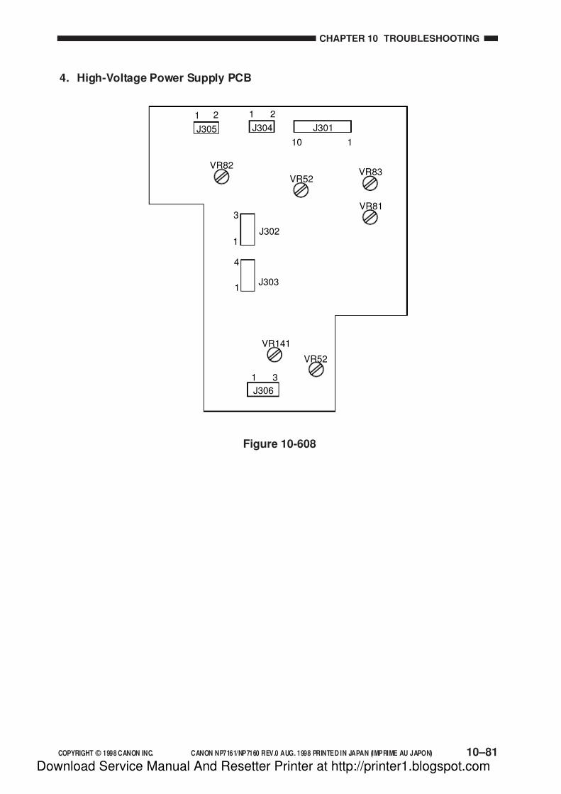
7/16/2019 Canon Np7161-Np7160 Copier Sm
http://slidepdf.com/reader/full/canon-np7161-np7160-copier-sm 311/345
COPYRIGHT © 1998 CANON INC. CANON NP7161/NP7160 REV.0 AUG. 1998 PRINTED IN JAPAN (IMPRIME AU JAPON) 10–81
CHAPTER 10 TROUBLESHOOTING
4. High-Voltage Power Supply PCB
J305
J302
3
1
21
J303
4
1
J304
21
J301
10 1
VR82
VR141
J306
VR52
31
VR83
VR81
VR52
Figure 10-608
Download Service Manual And Resetter Printer at http://printer1.blogspot.com
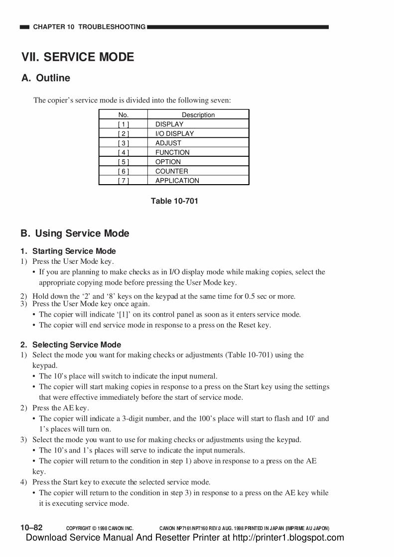
7/16/2019 Canon Np7161-Np7160 Copier Sm
http://slidepdf.com/reader/full/canon-np7161-np7160-copier-sm 312/345
10–82 COPYRIGHT © 1998 CANON INC. CANON NP7161/NP7160 REV.0 AUG. 1998 PRINTED IN JAPAN (IMPRIME AU JAPON)
CHAPTER 10 TROUBLESHOOTING
VII. SERVICE MODE
A. Outline
The copier’s service mode is divided into the following seven:
Table 10-701
DISPLAY
DescriptionNo.
[ 1 ]
I/O DISPLAY[ 2 ]
ADJUST[ 3 ]
FUNCTION[ 4 ]
OPTION[ 5 ]
COUNTER[ 6 ]
APPLICATION[ 7 ]
B. Using Service Mode
1. Starting Service Mode
1) Press the User Mode key.
• If you are planning to make checks as in I/O display mode while making copies, select the
appropriate copying mode before pressing the User Mode key.
2) Hold down the ‘2’ and ‘8’ keys on the keypad at the same time for 0.5 sec or more.3) Press the User Mode key once again.
• The copier will indicate ‘[1]’ on its control panel as soon as it enters service mode.
• The copier will end service mode in response to a press on the Reset key.
2. Selecting Service Mode
1) Select the mode you want for making checks or adjustments (Table 10-701) using the
keypad.
• The 10’s place will switch to indicate the input numeral.
• The copier will start making copies in response to a press on the Start key using the settings
that were effective immediately before the start of service mode.
2) Press the AE key.
• The copier will indicate a 3-digit number, and the 100’s place will start to flash and 10’ and
1’s places will turn on.
3) Select the mode you want to use for making checks or adjustments using the keypad.
• The 10’s and 1’s places will serve to indicate the input numerals.
• The copier will return to the condition in step 1) above in response to a press on the AE
key.
4) Press the Start key to execute the selected service mode.
• The copier will return to the condition in step 3) in response to a press on the AE key while
it is executing service mode.
Download Service Manual And Resetter Printer at http://printer1.blogspot.com

7/16/2019 Canon Np7161-Np7160 Copier Sm
http://slidepdf.com/reader/full/canon-np7161-np7160-copier-sm 313/345
COPYRIGHT © 1998 CANON INC. CANON NP7161/NP7160 REV.0 AUG. 1998 PRINTED IN JAPAN (IMPRIME AU JAPON) 10–83
CHAPTER 10 TROUBLESHOOTING
C. Using Adjust Mode and Function Mode
In adjust mode and function mode, the copier stores the settings made on the control panel in
the RAM on the DC controller PCB and use them to simulate the functions of conventional
variable resistors and switches.Figure 10-701 shows the information sheet stored behind the copier’s front door. Each copier
is adjusted at the factory, and the adjustment values are recorded in the sheet.
If you have replaced the DC controller PCB or initialized the RAM, you will have to enter
the values recorded in the information sheet into the RAM on the DC controller PCB. Moreover,
if you have entered any values newly in the field, be sure to record the value in this sheet.
Figure 10-701
AE_ADJ301
TYP
LMP_ADJ302
AE_SLOP303
REGIST305
LE_BLANK306
PG_RGST307
PG_BLANK308
TE_BLANK309
MF_ARCH319
CST1_ARCH320
CST2_ARCH321
LIGHT_5326
LNS_HP327MIRR_HP328
LNS_TBL329
MIRR_TBL330
MLT_CL331
MLT_TMG
MODEL_SW
332
DOC_ST_L701
519
Download Service Manual And Resetter Printer at http://printer1.blogspot.com

7/16/2019 Canon Np7161-Np7160 Copier Sm
http://slidepdf.com/reader/full/canon-np7161-np7160-copier-sm 314/345
10–84 COPYRIGHT © 1998 CANON INC. CANON NP7161/NP7160 REV.0 AUG. 1998 PRINTED IN JAPAN (IMPRIME AU JAPON)
CHAPTER 10 TROUBLESHOOTING
Indicates the type of jam. (See Table 10-702.)
Indicates the code of the fan that caused E805.
“01: exhaust fan at rear (FM2)
“02: exhaust fan at fount (FM4)
“03: sorter kit fan (FM5)
Indicates the most recent five jams. A press on ‘1’through ‘5’ keys will show the respective jams.
(See Table 10-702.)
Indicates the most recent five error codes. A press on
‘1’ through ‘5’ keys will show their respective error
codes and the number being pressed.
unit: °C
unit: °C
unit: °C
A press on the Start key will execute AE scanning.
The output voltage of the AE sensor is indicated in
decimal notation using three digits (e.g., 245 V will be
indicated as ‘245’).
Indicates the version of the program.
Indicates the release number of the program.
Indicates the history of the most recent five jams. A
press on the ‘1’ through ‘5’ keys will indicate the type
of their respective jams. (See Table 10-703.)
Indicates the history of the most recent five jams. A
press on the ‘1’ through ‘5’ keys will indicate the type
of their respective jams. (See Table 10-705.)
Indicates the type of jam. (See Table 10-703.)
Indicates alarm codes of the ADF. (See Table 10-
704.)
Indicates the version of the program.
Indicates the type of jam.
E805
Indicates a history of jams.
Indicates a history of errors.
Indicates the temperature detected by the fixing
main thermistor (TH1).
Indicates the temperature detected by the fixing
sub thermistor (TH2).
Indicates the temperature detected by the cleaner
thermistor (TH3).
Indicates the output voltage of the AE sensor.
Indicates the version of the ROM.
Indicates the release number of the ROM.
Indicates the jam history of the ADF.
Indicates the jam history of the sorter.
Indicates the type of jam in the ADF.
Indicates the type of warning for the ADF.
Indicates the version of the ROM of the ADF.
No. Description Remarks
D. Display Mode [1]
• To select an item, use the keypad.
• To execute an item, use the Start key.
• To cancel an item, use the Clear key.
101
106
107
108
109
110
111
112
113
114
115
116
117
118
119
Download Service Manual And Resetter Printer at http://printer1.blogspot.com

7/16/2019 Canon Np7161-Np7160 Copier Sm
http://slidepdf.com/reader/full/canon-np7161-np7160-copier-sm 315/345
COPYRIGHT © 1998 CANON INC. CANON NP7161/NP7160 REV.0 AUG. 1998 PRINTED IN JAPAN (IMPRIME AU JAPON) 10–85
CHAPTER 10 TROUBLESHOOTING
Indicates the release number of the ROM of the
ADF.
Indicates the type of jam in the sorter.
Indicates the tray warning for the sorter.
Indicates the stapling alarm for the sorter.
Indicates the version of the ROM of the sorter.
Indicates the release number of the ROM of the
sorter.
Checks the keys on the control panel.
Indicates the release number of the program.
Indicates the type of jam in the sorter. (See Table 10-705.)
Indicates the alarm code for the sorter. (See Table 10-
706.)
Indicates the alarm code for the sorter. (See Table 10-
707.)
Indicates the version of the program.
Indicates the release number of the program.
See p. 10-87.
No. Description Remarks
120
121
122
123
124
125
126
Guide to Jam Types (No. 101) and Jam History (No. 107)
• The type of jam is indicated using the following codes in the 10’s and 1’s places. In the case
of the history, the number corresponding to the keys on the keypad will be indicated in the
100’s place.
Table 10-702
Registration delay jam
Registration stationary jam
Delivery delay jam
Delivery stationary jam
ADF jam
Description Sensor
PS5
PS6
PS11
Code
01
02
04
05
40
Sorter jam50
Right door open jam
Registration paper sensor timing jam
06
03
PS5, PS6Power-on jam07
Download Service Manual And Resetter Printer at http://printer1.blogspot.com

7/16/2019 Canon Np7161-Np7160 Copier Sm
http://slidepdf.com/reader/full/canon-np7161-np7160-copier-sm 316/345
10–86 COPYRIGHT © 1998 CANON INC. CANON NP7161/NP7160 REV.0 AUG. 1998 PRINTED IN JAPAN (IMPRIME AU JAPON)
CHAPTER 10 TROUBLESHOOTING
Guide to ADF Jam History (No. 115) and ADF Jam Type (No. 117)
• The type of jam is indicated using the following codes in the 10’s and 1’s places. In the case
of the history, the number corresponding to the keys on the keypad will be indicated in the
100’s place.
Table 10-705
DescriptionCode
03
04
05
06
07
08
Feeding delay
Feeding stationary
Timing
Staple (stapler sorter only)
Power-on
Door open
Guide to Sorter Jam History (No. 116) and Sorter Jam Type (No. 121)• The type of jam is indicated using the following codes in the 10’s and 1’s places. In the case
of the history, the number corresponding to the keys on the keypad will be indicated in the
100’s place.
Guide to ADF Warning (No. 118)
Table 10-704
DescriptionCode
02
0304
05
11
12
13
14
Tray sensor off
Separation faultSeparation skew
Separation stopper override
Original pages-jam recovery pages mismatch
Original page in excess of 100
Original extraction
Original size error
Separation extraction
Separation delay
Pick-up delay
Pick-up leading edge skew
Pick-up stationary
Pick-up double feeding
Pick-up trailing edge skew
DescriptionCode
01
02
03
04
05
06
07
Pick-up trailing edge retreat08
Pick-up fault (leading edge)09
Delivery delay41
Delivery stationary42Open81
Door open82
Jam original page84
Double feeding87
Table 10-703
Download Service Manual And Resetter Printer at http://printer1.blogspot.com

7/16/2019 Canon Np7161-Np7160 Copier Sm
http://slidepdf.com/reader/full/canon-np7161-np7160-copier-sm 317/345
COPYRIGHT © 1998 CANON INC. CANON NP7161/NP7160 REV.0 AUG. 1998 PRINTED IN JAPAN (IMPRIME AU JAPON) 10–87
CHAPTER 10 TROUBLESHOOTING
Guide to Sorter Tray Warning (No. 122)
DescriptionCode
01
02
03
04
05
06
0708
09
0A
Stapler down
Staple
Stapler safety protection
Edging fault
Stapling overstacking
Staple stacking limit
Mixed paper sizes (breadthwise)Staple unit absent
Paper in stapler
Staple absent
Table 10-706
Overstacking
DescriptionCode
02
Table 10-707
Checking the Control Panel Keys (No. 126)
1) While the copier is in mode No. 126, press all keys on the control panel except the Start key.
2) Press the Start key.
• If ‘000’ is indicated on the control panel, all keys are normal.
• If an error key is found, the copier will indicate its respective code (Table 10-708).
If multiple keys are found to be faulty, the copier will indicate the lowest-number code
only.
Guide to Sorter Stapling Warning (No. 123)
Sorter key
KeyCode
1
Number 1 key
KeyCode
22
Image Combination / Two-page Separation key4
Number 2 key23
AE key5
Number 3 key24
Fit Image key31
Number 4 key25
Photo key3
Number 5 key26
Reduce key8
Number 6 key27
1:1 key9
Number 7 key28
Enlarge key10
Number 8 key29
Paper Select key11
Number 9 key30
Auto Zoom key2
Number 0 key21
% key12
ID key20
- Zoom key14
Clear key19
+ Zoom key13
Start key7
Reset key15
Stop key6
Additional Functions key16
Energy Saver key18
Interrupt key17
Table 10-708
Download Service Manual And Resetter Printer at http://printer1.blogspot.com
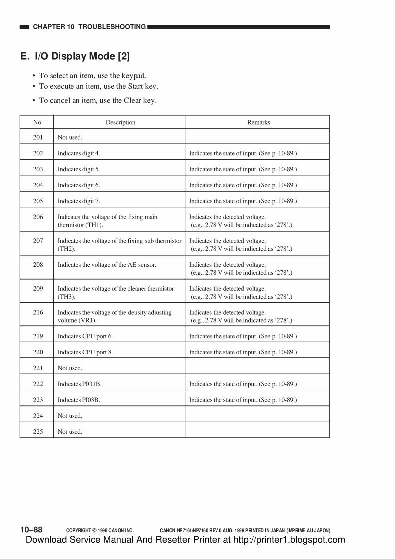
7/16/2019 Canon Np7161-Np7160 Copier Sm
http://slidepdf.com/reader/full/canon-np7161-np7160-copier-sm 318/345
10–88 COPYRIGHT © 1998 CANON INC. CANON NP7161/NP7160 REV.0 AUG. 1998 PRINTED IN JAPAN (IMPRIME AU JAPON)
CHAPTER 10 TROUBLESHOOTING
No. Description Remarks
201
202
203
204
205
206
207
208
209
216
219
220
221
222
223
224
225
Not used.
Indicates digit 4.
Indicates digit 5.
Indicates digit 6.
Indicates digit 7.
Indicates the voltage of the fixing main
thermistor (TH1).
Indicates the voltage of the fixing sub thermistor
(TH2).
Indicates the voltage of the AE sensor.
Indicates the voltage of the cleaner thermistor
(TH3).
Indicates the voltage of the density adjusting
volume (VR1).
Indicates CPU port 6.
Indicates CPU port 8.
Not used.
Indicates PIO1B.
Indicates PI03B.
Not used.
Not used.
Indicates the state of input. (See p. 10-89.)
Indicates the state of input. (See p. 10-89.)
Indicates the state of input. (See p. 10-89.)
Indicates the state of input. (See p. 10-89.)
Indicates the detected voltage.
(e.g., 2.78 V will be indicated as ‘278’.)
Indicates the detected voltage.
(e.g., 2.78 V will be indicated as ‘278’.)
Indicates the detected voltage.
(e.g., 2.78 V will be indicated as ‘278’.)
Indicates the detected voltage.
(e.g., 2.78 V will be indicated as ‘278’.)
Indicates the detected voltage.
(e.g., 2.78 V will be indicated as ‘278’.)
Indicates the state of input. (See p. 10-89.)
Indicates the state of input. (See p. 10-89.)
Indicates the state of input. (See p. 10-89.)
Indicates the state of input. (See p. 10-89.)
E. I/O Display Mode [2]
• To select an item, use the keypad.
• To execute an item, use the Start key.
• To cancel an item, use the Clear key.
Download Service Manual And Resetter Printer at http://printer1.blogspot.com
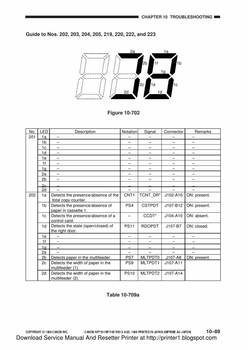
7/16/2019 Canon Np7161-Np7160 Copier Sm
http://slidepdf.com/reader/full/canon-np7161-np7160-copier-sm 319/345
COPYRIGHT © 1998 CANON INC. CANON NP7161/NP7160 REV.0 AUG. 1998 PRINTED IN JAPAN (IMPRIME AU JAPON) 10–89
CHAPTER 10 TROUBLESHOOTING
Guide to Nos. 202, 203, 204, 205, 219, 220, 222, and 223
1a
1g
1b
1c
1f
1e
1d
2a
2b
2c
2d
Figure 10-702
Detects the presence/absence of thetotal copy counter.
ON: present.
Description ConnectorNotation Signal RemarksNo.
202
LED
1a
Detects the presence/absence ofpaper in cassette 1.
ON: present.1b
Detects the presence/absence of acontrol card.
ON: absent.1c
Detects the state (open/closed) ofthe right door.
ON: closed.1d
– – 2a
Detects paper in the multifeeder. ON: present.2b
Detects the width of paper in themultifeeder (1).
2c
Detects the width of paper in themultifeeder (2).
2d
– – 1e
1f
– – 1g
CNT1
PS4
–
PS11
–
PS7
PS9
PS10
–
–
TCNT_DR*
CSTPDT
CCDT*
RDOPDT
–
MLTPDT0
MLTPDT1
MLTPDT2
–
–
J102-A10
J107-B12
J104-A10
J107-B7
–
J107-A8
J107-A11
J107-A14
–
–
– – 201 1a
– – 1b
– – 1c
– – 1d
– – 2a
– – 2b
– – 2c– – 2d
1e – –
1f
– – 1g
–
–
–
–
–
–
– –
–
–
–
–
–
–
–
–
– –
–
–
–
–
–
–
–
–
– – – – –
– –
–
–
– – – – –
Table 10-709a
Download Service Manual And Resetter Printer at http://printer1.blogspot.com
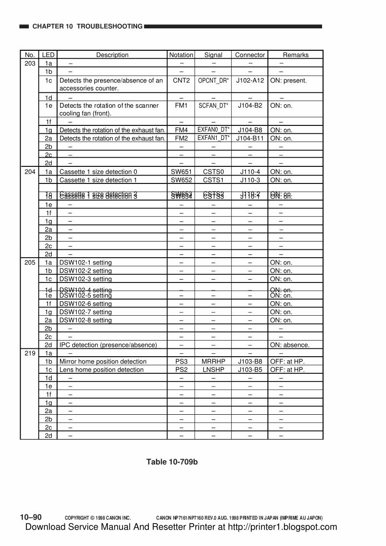
7/16/2019 Canon Np7161-Np7160 Copier Sm
http://slidepdf.com/reader/full/canon-np7161-np7160-copier-sm 320/345
10–90 COPYRIGHT © 1998 CANON INC. CANON NP7161/NP7160 REV.0 AUG. 1998 PRINTED IN JAPAN (IMPRIME AU JAPON)
CHAPTER 10 TROUBLESHOOTING
Table 10-709b
Description ConnectorNotation Signal RemarksNo. LED
DSW102-1 setting ON: on.205 1a
DSW102-2 setting ON: on.1b
DSW102-3 setting ON: on.1c
DSW102-4 setting ON: on.1d
DSW102-8 setting ON: on.2a
– – 2b
– – 2c
IPC detection (presence/absence) ON: absence.2d
DSW102-5 setting ON: on.1e
DSW102-6 setting ON: on.1f
DSW102-7 setting ON: on.
–
–
–
–
–
–
–
–
–
–
–
–
–
–
–
–
–
–
–
–
–
–
–
–
–
–
–
–
–
–
–
–
– 1g
Cassette 1 size detection 0 ON: on.204 1a
Cassette 1 size detection 1 ON: on.1b
Cassette 1 size detection 2 ON: on.1c Cassette 1 size detection 3 ON: on.1d
2a
– – 2b
– – 2c
– – 2d
1e
1f
1g
SW651
SW652
SW653SW654
–
–
–
–
–
–
–
CSTS0
CSTS1
CSTS2CSTS3
–
–
–
–
–
–
–
J110-4
J110-3
J110-2J110-1
–
–
–
–
– – 2b
– – 2c
– – 2d
–
–
–
–
–
–
–
–
–
–
–
–
– – 219 1a
Mirror home position detection OFF: at HP.1b
Lens home position detection OFF: at HP.1c
– – 1d
– – 2a
– – 1e
– – 1f
– – 1g
–
PS3
PS2
–
–
–
–
–
–
MRRHP
LNSHP
–
–
–
–
–
–
J103-B8
J103-B5
–
–
–
–
–
203 1a
1b
Detects the presence/absence of anaccessories counter.
ON: present.1c
1d
Detects the rotation of the exhaust fan. ON: on.2a
– – 2b
– – 2c
– – 2d
1e Detects the rotation of the scannercooling fan (front).
ON: on.
1f
Detects the rotation of the exhaust fan. ON: on.1g
CNT2
–
FM2
–
–
–
FM1
FM4
OPCNT_DR*
–
EXFAN1_DT*
–
–
–
SCFAN_DT*
EXFAN0_DT*
J102-A12
–
J104-B11
–
– – – – –
–
–
J104-B2
J104-B8
–
–
– – – –
– – – – –
–
– –
– –
– –
– –
Download Service Manual And Resetter Printer at http://printer1.blogspot.com

7/16/2019 Canon Np7161-Np7160 Copier Sm
http://slidepdf.com/reader/full/canon-np7161-np7160-copier-sm 321/345
COPYRIGHT © 1998 CANON INC. CANON NP7161/NP7160 REV.0 AUG. 1998 PRINTED IN JAPAN (IMPRIME AU JAPON) 10–91
CHAPTER 10 TROUBLESHOOTING
Table 10-709c
Description ConnectorNotation Signal RemarksNo. LED
Waste toner box full detection
Main heater triac short circuit detection
ON: full.222 1a
ON: on.1b
– – 1c
Scanning lamp on detection ON: on.1d
2a
Toner level detection ON: present.1e
Delivery detection ON: present.1fPre-registration paper detection ON: present.1g
– – 223 1a
– – 1b
– – 1c
– – 1d
Main motor (M1) lock detection ON: motor off.2a
Zero-cross direction detection – 1e
Waste toner feedscrew lock detection1f
–
H1
–
LA1
–
TS1
PS6PS5
–
–
–
–
M1
–
PS8
–
TNFDT
–
–
LMPDT
–
TNEMP
EXITPDRGPDT
–
–
–
–
MM_LKDT*
–
TRQMLDT
–
J106-9
–
–
J106-6
–
J102-B2
J124-2J107-A2
–
–
–
–
– – 2b
– – 2c
– – 2d
–
–
–
–
–
–
–
–
–
– – 2b
– – 2c
– – 2d
–
–
–
–
–
–
–
–
–
J106-16
–
J106-10
– 1g
– – 2b
– – 2c
– – 2d
–
–
–
–
–
–
–
–
–
– – 221 1a
– – 1b
– – 1c
– – 1d
– – 2a
– – 1e – – 1f
– – 1g
–
–
–
–
–
– –
–
–
–
–
–
–
– –
–
–
–
–
–
–
– –
–
– – 2b
– – 2c
– – 2d
–
–
–
–
–
–
–
–
–
Scanner home position detection OFF: at HP.220 1a
– – 1b
– – 1c
– – 1d
– – 2a
– – 1e– – 1f
– – 1g
PS1
–
–
–
–
– –
–
SCHP
–
–
–
–
– –
–
J103-B2
–
–
–
–
– –
–
–
– –
–
Download Service Manual And Resetter Printer at http://printer1.blogspot.com

7/16/2019 Canon Np7161-Np7160 Copier Sm
http://slidepdf.com/reader/full/canon-np7161-np7160-copier-sm 322/345
10–92 COPYRIGHT © 1998 CANON INC. CANON NP7161/NP7160 REV.0 AUG. 1998 PRINTED IN JAPAN (IMPRIME AU JAPON)
CHAPTER 10 TROUBLESHOOTING
F. Adjust Mode [3]
• To select an item, use the keypad.
• To execute an item, press the Start key.
• To change a setting, use the keypad or the +/- Zoom key.• To enter a value, press the Start key.
• To remove an item, press the AE key.
No. Description Remarks
Executes AE auto adjustment.
Adjust the lamp intensity for AE mode.
Adjusts the copy density (developing
bias) slope for AE mode.
Adjust the leading edge margin
(registration roller clutch CL1 activation
timing).
Adjusts the leading edge non-image
width (blank exposure lamp LA3 de-
activation timing).
Adjusts the leading edge registration on
right pages in page separation
(registration roller clutch CL1 activation
timing).
Adjusts the leading edge margin on right
pages in page separation mode (blank
exposure lamp LA3 de-activation
timing).
Adjusts the trailing edge margin (blank exposure lamp LA3 activation timing).
Adjusts the arching in multifeeder mode
(de-activation of the multifeeder pick-up
roller clutch CL3).
Adjusts the arching in cassette 1 pick-up
mode (de-activation of pick-up roller
clutch CL2).
Adjusts the arching in cassette 2 pick-up
mode (de-activation of the pick-up rollerclutch).
301
302
303
305
306
307
308
309
319
320
321
Settings
—
450 – 750
(120V model)
0 – 590
(230V model)
0 – 255
0 – 500
0 – 500
0 – 500
0 – 500
0 – 500
0 – 200
0 – 100
0 – 100
Use it to perform AE adjustment.
(See p. 10-19.)
A higher setting will increase the intensity of
the scanning lamp (LA1), making the copies
lighter. (Use it when performing AE
adjustment.)
A higher setting will make the copies lighter.
(Use it when performing AE adjustment.)
A higher setting will delay pick-up of copy paper
in relation to the image, thereby decreasing the
leading edge margin. (unit: 0.21 mm)
A higher setting will delay de-activation of the
lamp, thereby increasing the leading edge non-
image width. (unit: 0.21 mm)
A higher setting will delay pick-up of copy
paper in relation to the image, thereby
decreasing the leading edge margin. (unit: 0.21
mm)
A higher setting will delay de-activation of the
lamp, thereby increasing the leading edge non-
image width. (unit: 0.21 mm)
A higher setting will advance activation of thelamp, thereby increasing the trailing edge
margin. (unit: 0.21 mm)
A higher setting will delay deactivation of the
clutch, thereby increasing arching. (unit; 0.21
mm)
A higher setting will increase the arching.
(unit: 0.42 mm)
A higher setting will delay de-activation of the
clutch, thereby increasing the arching. (unit:0.42 mm)
Download Service Manual And Resetter Printer at http://printer1.blogspot.com
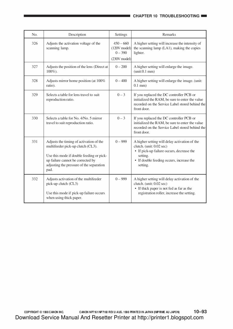
7/16/2019 Canon Np7161-Np7160 Copier Sm
http://slidepdf.com/reader/full/canon-np7161-np7160-copier-sm 323/345
COPYRIGHT © 1998 CANON INC. CANON NP7161/NP7160 REV.0 AUG. 1998 PRINTED IN JAPAN (IMPRIME AU JAPON) 10–93
CHAPTER 10 TROUBLESHOOTING
450 – 660
(120V model)
0 – 390
(230V model)
0 – 200
0 – 400
0 – 3
0 – 3
0 – 999
0 – 999
No. Description RemarksSettings
326
327
328
329
330
331
332
Adjusts the activation voltage of the
scanning lamp.
Adjusts the position of the lens (Direct at
100%).
Adjusts mirror home position (at 100%
ratio).
Selects a table for lens travel to suit
reproduction ratio.
Selects a table for No. 4/No. 5 mirror
travel to suit reproduction ratio.
Adjusts the timing of activation of the
multifeeder pick-up clutch (CL3).
Use this mode if double feeding or pick-
up failure cannot be corrected by
adjusting the pressure of the separation
pad.
Adjusts activation of the multifeeder
pick-up clutch (CL3)
Use this mode if pick-up failure occurs
when using thick paper.
A higher setting will increase the intensity of
the scanning lamp (LA1), making the copies
lighter.
A higher setting will enlarge the image.
(unit:0.1 mm)
A higher setting will enlarge the image. (unit:
0.1 mm)
If you replaced the DC controller PCB or
initialized the RAM, be sure to enter the value
recorded on the Service Label stored behind the
front door.
If you replaced the DC controller PCB or
initialized the RAM, be sure to enter the value
recorded on the Service Label stored behind the
front door.
A higher setting will delay activation of the
clutch. (unit: 0.02 sec)
• If pick-up failure occurs, decrease the
setting.
• If double feeding occurs, increase the
setting.
A higher setting will delay activation of the
clutch. (unit: 0.02 sec)
• If thick paper is not fed as far as the
registration roller, increase the setting.
Download Service Manual And Resetter Printer at http://printer1.blogspot.com

7/16/2019 Canon Np7161-Np7160 Copier Sm
http://slidepdf.com/reader/full/canon-np7161-np7160-copier-sm 324/345
10–94 COPYRIGHT © 1998 CANON INC. CANON NP7161/NP7160 REV.0 AUG. 1998 PRINTED IN JAPAN (IMPRIME AU JAPON)
CHAPTER 10 TROUBLESHOOTING
Stirs toner.
Releases the multifeeder holding plate.
Drum unit installation mode.
Execute this mode at the time of drum unit
installation or replacement.
Checks the fixing nip.
Checks the activation of the scanning lamp
(LA1).
Checks all indicators on the control panel.
Checks the forward movement of the scanning
lamp.
Checks the activation of the pre-exposure lamp(LA2).
Initializes E000, E001, E002, E003, or E004.
Moves the scanner, lens, and No. 4/No. 5 mirror
unit.
Initializes the back-up RAM.
401
402
403
406
408
409
410
411
412
440
450
The developing assembly (main motor) will rotate 4min. (The pre-exposure lamp LA2 and the blank
exposure lamp LA3 will turn on, and all high-voltage
outputs will turn off.)
Releases the multifeeder holding plate.
The drum unit and developing assembly will rotate 40
sec.
Checks the fixing nip. (The Stop key will be
disabled.)
The scanning lamp will turn on for 5 sec.
All LEDs on the control panel will turn on for 5 sec.
The scanner moves forward while the + key is held
down.
The scanner moves in reverse while the - key is held
down.
The pre-exposure lamp will turn on.
Press the Start key while the error code (E000, E001,
E002, E003, or E004) is indicated.
Execute this mode before transporting the machine so
that the scanner, lens, and No. 4/No. 5 mirror unit will
be positioned for transportation.
Press ‘1’ on the keypad and the Start key in sequence.
(The power will turn off, initializing all RAM data.)
G. Function Mode [4]
• To select an item, use the keypad.
• To execute an item, use the Start key.
• To stop an item, use the Stop key.• To clear an item, use the Clear key.
Caution:
Be sure that the copier is in standby state when executing any item.
No. Description Remarks
Download Service Manual And Resetter Printer at http://printer1.blogspot.com
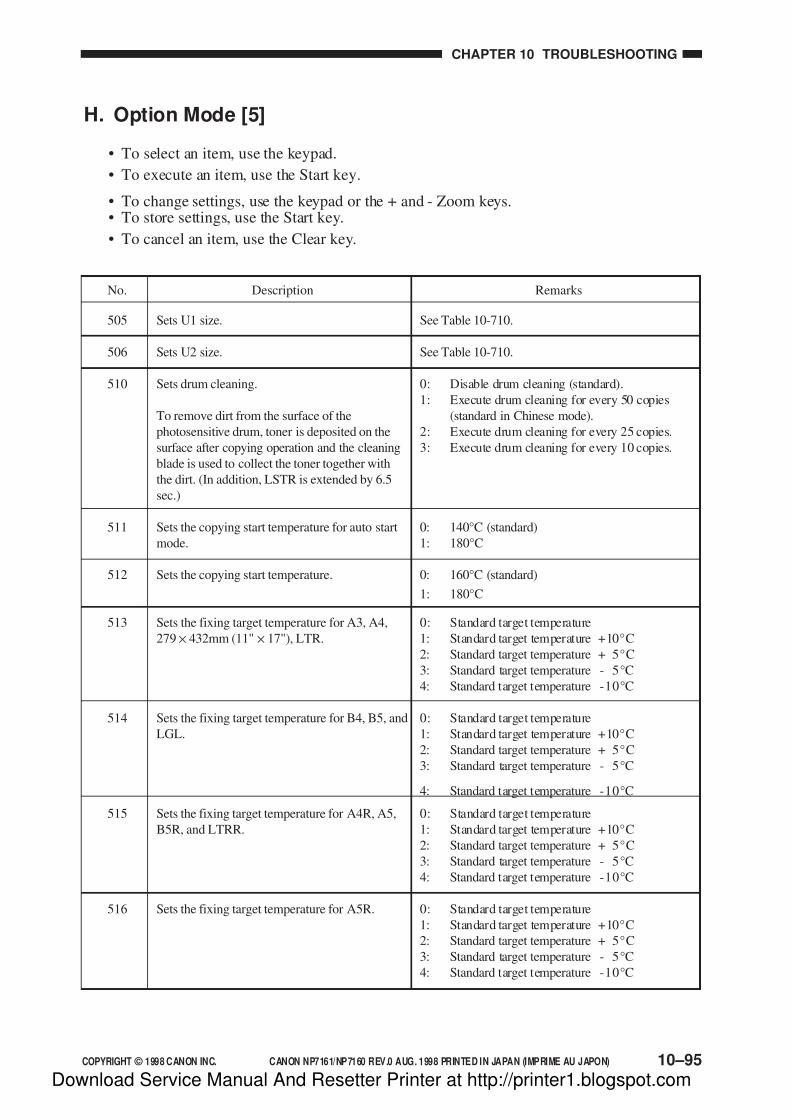
7/16/2019 Canon Np7161-Np7160 Copier Sm
http://slidepdf.com/reader/full/canon-np7161-np7160-copier-sm 325/345
COPYRIGHT © 1998 CANON INC. CANON NP7161/NP7160 REV.0 AUG. 1998 PRINTED IN JAPAN (IMPRIME AU JAPON) 10–95
CHAPTER 10 TROUBLESHOOTING
See Table 10-710.
See Table 10-710.
0: Disable drum cleaning (standard).
1: Execute drum cleaning for every 50 copies
(standard in Chinese mode).
2: Execute drum cleaning for every 25 copies.
3: Execute drum cleaning for every 10 copies.
0: 140°C (standard)
1: 180°C
0: 160°C (standard)
1: 180°C
0: Standard target temperature
1: Standard target temperature +10°C
2: Standard target temperature + 5°C
3: Standard target temperature - 5°C
4: Standard target temperature -10°C
0: Standard target temperature
1: Standard target temperature +10°C
2: Standard target temperature + 5°C
3: Standard target temperature - 5°C
4: Standard target temperature -10°C
0: Standard target temperature
1: Standard target temperature +10°C
2: Standard target temperature + 5°C
3: Standard target temperature - 5°C
4: Standard target temperature -10°C
0: Standard target temperature
1: Standard target temperature +10°C
2: Standard target temperature + 5°C
3: Standard target temperature - 5°C
4: Standard target temperature -10°C
Sets U1 size.
Sets U2 size.
Sets drum cleaning.
To remove dirt from the surface of the
photosensitive drum, toner is deposited on the
surface after copying operation and the cleaning
blade is used to collect the toner together with
the dirt. (In addition, LSTR is extended by 6.5
sec.)
Sets the copying start temperature for auto start
mode.
Sets the copying start temperature.
Sets the fixing target temperature for A3, A4,
279 × 432mm (11" × 17"), LTR.
Sets the fixing target temperature for B4, B5, and
LGL.
Sets the fixing target temperature for A4R, A5,
B5R, and LTRR.
Sets the fixing target temperature for A5R.
505
506
510
511
512
513
514
515
516
H. Option Mode [5]
• To select an item, use the keypad.
• To execute an item, use the Start key.
• To change settings, use the keypad or the + and - Zoom keys.• To store settings, use the Start key.
• To cancel an item, use the Clear key.
No. Description Remarks
Download Service Manual And Resetter Printer at http://printer1.blogspot.com

7/16/2019 Canon Np7161-Np7160 Copier Sm
http://slidepdf.com/reader/full/canon-np7161-np7160-copier-sm 326/345
10–96 COPYRIGHT © 1998 CANON INC. CANON NP7161/NP7160 REV.0 AUG. 1998 PRINTED IN JAPAN (IMPRIME AU JAPON)
CHAPTER 10 TROUBLESHOOTING
0: Make a retry (standard).
Indicates the Jam message in response to the
second registration delay jam.
1: Do not make a retry.Indicates the Jam message in response to the
first registration delay jam.
0: Increment by 1 for all sizes (standard).
1: Increment by 2 for all sizes.
0: Normal (standard)
1: China
The standard target temperature for fixing will
be lowered by 10°C. In addition, ‘U14’ will be
added to user mode.
No. Description Remarks
517
518
519
Enables/disables retry for cassette pick-up
operation.
In cassette pick-up mode, pick-up operation willbe executed once again without indicating the
first registration delay jam.
Sets the count for the control card in multifeeder
pick-up.
Selects settings to suit the site of installation.
Making changes using this mode will change the
settings under ‘510’ as follows:
• If ‘1’ is selected instead of ‘0’ in this mode,
‘1’ will be set under ‘510’.• If ‘0’ is selected instead of ‘1’ in this mode,
‘0’ will be set under ‘510’.
However, ‘510’ settings may be changed after
making changes in this mode.
Paper Sizes Available under No. 505/506
Table 10-710
ARGENTINE OFICIO
ARGENTINE LEGAL
Paper Size (vertical x horizontal in mm)Code
1
BOLIVIA0
2
AUSTRALIAN FOOLSCAP3
FOOLSCAP4
FOLIO5
GOVERNMENT LEGAL6
ECUADORAN OFICIO7
OFFICIO8
ARGENTINE LETTER R9
KOREAN LEGAL R10
GOVERNMENT LETTER R11ARGENTINE LETTER12
GOVERNMENT LETTER13
KOREAN LEGAL
220.0 x 340.0
220.0 x 340.0
216.0 x 355.0
206.0 x 337.0
215.9 x 330.2
210.0 x 330.0
203.2 x 330.2
220.0 x 320.0
216.0 x 317.0
220.0 x 280.0
190.0 x 268.0
203.2 x 266.7280.0 x 220.0
266.7 x 203.2
268.0 x 190.014
Download Service Manual And Resetter Printer at http://printer1.blogspot.com
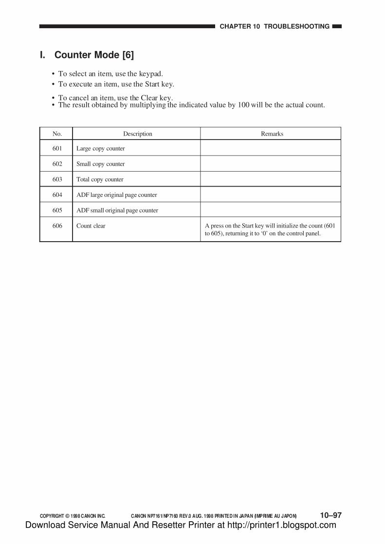
7/16/2019 Canon Np7161-Np7160 Copier Sm
http://slidepdf.com/reader/full/canon-np7161-np7160-copier-sm 327/345
COPYRIGHT © 1998 CANON INC. CANON NP7161/NP7160 REV.0 AUG. 1998 PRINTED IN JAPAN (IMPRIME AU JAPON) 10–97
CHAPTER 10 TROUBLESHOOTING
No. Description Remarks
601
602
603
604
605
606
Large copy counter
Small copy counter
Total copy counter
ADF large original page counter
ADF small original page counter
Count clear A press on the Start key will initialize the count (601
to 605), returning it to ‘0’ on the control panel.
I. Counter Mode [6]
• To select an item, use the keypad.
• To execute an item, use the Start key.
• To cancel an item, use the Clear key.• The result obtained by multiplying the indicated value by 100 will be the actual count.
Download Service Manual And Resetter Printer at http://printer1.blogspot.com
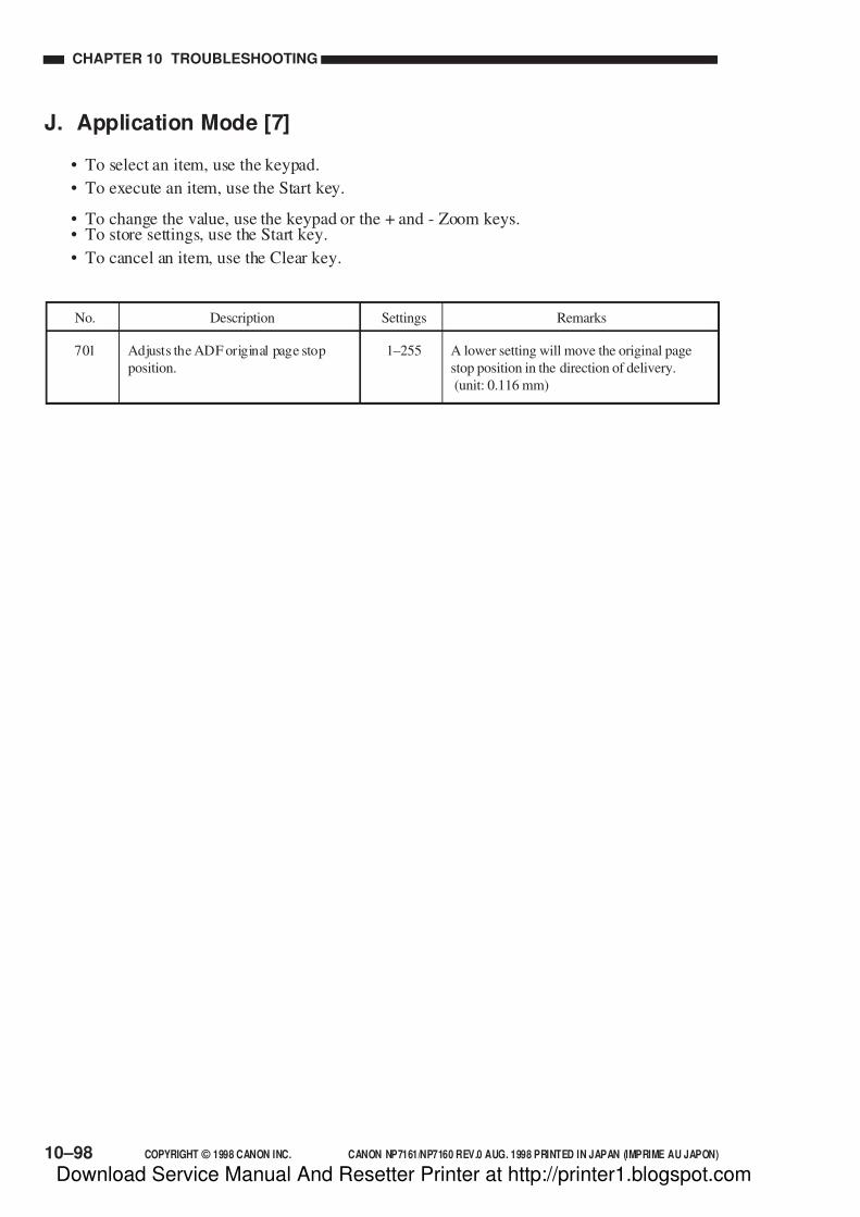
7/16/2019 Canon Np7161-Np7160 Copier Sm
http://slidepdf.com/reader/full/canon-np7161-np7160-copier-sm 328/345
10–98 COPYRIGHT © 1998 CANON INC. CANON NP7161/NP7160 REV.0 AUG. 1998 PRINTED IN JAPAN (IMPRIME AU JAPON)
CHAPTER 10 TROUBLESHOOTING
J. Application Mode [7]
• To select an item, use the keypad.
• To execute an item, use the Start key.
• To change the value, use the keypad or the + and - Zoom keys.• To store settings, use the Start key.
• To cancel an item, use the Clear key.
No. Description RemarksSettings
701 Adjusts the ADF original page stop
position.
A lower setting will move the original page
stop position in the direction of delivery.
(unit: 0.116 mm)
1–255
Download Service Manual And Resetter Printer at http://printer1.blogspot.com
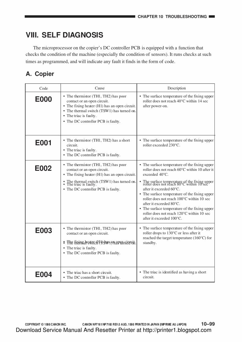
7/16/2019 Canon Np7161-Np7160 Copier Sm
http://slidepdf.com/reader/full/canon-np7161-np7160-copier-sm 329/345
COPYRIGHT © 1998 CANON INC. CANON NP7161/NP7160 REV.0 AUG. 1998 PRINTED IN JAPAN (IMPRIME AU JAPON) 10–99
CHAPTER 10 TROUBLESHOOTING
VIII. SELF DIAGNOSIS
The microprocessor on the copier’s DC controller PCB is equipped with a function that
checks the condition of the machine (especially the condition of sensors). It runs checks at such
times as programmed, and will indicate any fault it finds in the form of code.
A. Copier
E000• The thermistor (TH1, TH2) has poor
contact or an open circuit.
• The fixing heater (H1) has an open circuit.
• The thermal switch (TSW1) has turned on.
• The triac is faulty.
• The DC controller PCB is faulty.
• The thermistor (TH1, TH2) has a short
circuit.
• The triac is faulty.
• The DC controller PCB is faulty.
• The thermistor (TH1, TH2) has poor
contact or an open circuit.
• The fixing heater (H1) has an open circuit.
• The thermal switch (TSW1) has turned on.• The triac is faulty.
• The DC controller PCB is faulty.
• The thermistor (TH1, TH2) has poor
contact or an open circuit.
• The fixing heater (H1) has an open circuit.• The thermal switch (TSW1) has turned on.
• The triac is faulty.
• The DC controller PCB is faulty.
• The triac has a short circuit.
• The DC controller PCB is faulty.
• The surface temperature of the fixing upper
roller does not reach 40°C within 14 sec
after power-on.
• The surface temperature of the fixing upper
roller exceeded 230°C.
• The surface temperature of the fixing upper
roller does not reach 60°C within 10 after it
exceeded 40°C.
• The surface temperature of the fixing upperroller does not reach 80°C within 10 sec
after it exceeded 60°C.
• The surface temperature of the fixing upper
roller does not reach 100°C within 10 sec
after it exceeded 80°C.
• The surface temperature of the fixing upper
roller does not reach 120°C within 10 sec
after it exceeded 100°C.
• The surface temperature of the fixing upper
roller drops to 130°C or less after it
reached the target temperature (160°C) for
standby.
• The triac is identified as having a short
circuit.
Code Cause Description
E001
E002
E004
E003
Download Service Manual And Resetter Printer at http://printer1.blogspot.com

7/16/2019 Canon Np7161-Np7160 Copier Sm
http://slidepdf.com/reader/full/canon-np7161-np7160-copier-sm 330/345
10–100 COPYRIGHT © 1998 CANON INC. CANON NP7161/NP7160 REV.0 AUG. 1998 PRINTED IN JAPAN (IMPRIME AU JAPON)
CHAPTER 10 TROUBLESHOOTING
• The main motor lock detection signal
(MM_LKDT*) is detected for 1 sec
continuously while the main motor is being
driven.
• The waste toner feedscrew lock detection
signal (TRQMLDT) does not switch for
0.5 sec or more while the main motor is
being driven.
• The total copy counter is identified to have
an open circuit when the Start key is
pressed or when the counter is driven.
• The accessories counter is identified as
having an open circuit when the Start key
is pressed or the couter is being driven.
• The scanner does not return to home
position within a specific period of time
when it is being moved.
• The scanner home position sensor (PS1)
remains on during image exposure
(forward movement).
• The No. 4/No. 5 mirror unit does not turn
on or off the mirror home position sensor
(PS3) within a specific period of time
while the No. 4/No. 5 mirror unit is beingmoved.
• The lens unit does not turn on or off the
lens home position sensor (PS2) within a
specific period of time when the lens unit is
being moved.
• The scanning lamp turns on during
standby.
• The scanning lamp turns off during
copying.
• The intervals of the zero-cross signals
exceed the allowed intervals for 50/60 Hz.
E010
Code Cause Description
• The main motor (M1) is faulty.
• The DC controller PCB is faulty.
• The waste toner feedscrew is locked.
• The waste toner feedscrew lock sensor
(PS8) is faulty.
• The DC controller PCB is faulty.
• The total copy counter has an open
circuit.
• The DC controller PCB is faulty.
• The accessories counter has an open
circuit.• The DC controller PCB is faulty.
• The scanner home position sensor (PS1)
is faulty.
• The scanner motor (M2) is faulty.
• The DC controller PCB is faulty.
• The mirror home position sensor (PS3) is
faulty.
• The mirror motor (M4) is faulty.
• The DC controller PCB is faulty.
• The lens home position sensor (PS2) is
faulty.
• The lens motor (M3) is faulty.
• The DC controller PCB is faulty.
• The lamp regulator PCB is faulty.
• The DC controller PCB is faulty.
• The power supply frequency is faulty.
• The power supply PCB is faulty.
E030
E013
E031
(E202)No code
indication. Keys
are disabled.
(Note 2)
E208
E210
E261
E220
Download Service Manual And Resetter Printer at http://printer1.blogspot.com

7/16/2019 Canon Np7161-Np7160 Copier Sm
http://slidepdf.com/reader/full/canon-np7161-np7160-copier-sm 331/345
COPYRIGHT © 1998 CANON INC. CANON NP7161/NP7160 REV.0 AUG. 1998 PRINTED IN JAPAN (IMPRIME AU JAPON) 10–101
CHAPTER 10 TROUBLESHOOTING
• IC114 (IPC) on the DC controller PCB
cannot be initialized at power -on.
• An IPC communication error has beendetected twice or more within 1 sec at
power-on.
• A communication error with the ADF
controller PCB cannot be cleared.
• A condition in which a response from the
Remote Diagnostic Device II cannot be
received occurred three times
continuously.
• The Remote diagnostic Device II
communicates an interruption of count
pulses.
• An open circuit is detected for 5 V or 24 V
at power-on.
• The exhaust fan drive detection signal
(EXFAN1_DT*, FXFAN0_DT*) cannot
be detected 0.5 sec after the start of the
exhaust fan (FM2, FM4).
• The cleaner thermistor (TH3) detects 55°Cor more.
• The DC controller PCB is faulty.
• The DC controller PCB is faulty.
• The DC controller PCB is faulty.
• The ADF controller PCB is fault.
• The ADF cable is faulty.
• The DC controller PCB is faulty.
• The Remote Diagnostic Device II PCB is
faulty.
• The auto power-off circuit has an open
circuit.
• The DC controller PCB is faulty.
• The exhaust fan (FM2, FM4) is faulty.
• The DC controller PCB is faulty.
• The ozone filter is clogged.• The cleaner thermistor (TH3) has poor
contact or an open circuit.
• The DC controller PCB is faulty.
E710
E805
Code Cause Description
E711
E712
E717
E800
E821
Download Service Manual And Resetter Printer at http://printer1.blogspot.com

7/16/2019 Canon Np7161-Np7160 Copier Sm
http://slidepdf.com/reader/full/canon-np7161-np7160-copier-sm 332/345
10–102 COPYRIGHT © 1998 CANON INC. CANON NP7161/NP7160 REV.0 AUG. 1998 PRINTED IN JAPAN (IMPRIME AU JAPON)
CHAPTER 10 TROUBLESHOOTING
Note:
1. When the diagnostic function has turned on, the copier can be reset by turning it off
once. This, however, does not apply to E000, E001, E002, E003, or E004.
This is to prevent the user from resetting the copier easily when the error is caused by
an open circuit in the thermistor, otherwise overheating and damaging the fixing
roller.
Normally, the copier will automatically turn off in about 4 sec if it is turned on
without clearing E000 through E004.
To clear E000 through E004, operate as follows:
1) Select ‘412’ (clear E000–E004) in service mode.
• The copier’s control panel indicates the respective error code.
2) Press the Start key.
3) The copier will automatically turn off, clearing the error.
2. E202 may be checked using ‘108’ in service mode (error history indication).
Download Service Manual And Resetter Printer at http://printer1.blogspot.com

7/16/2019 Canon Np7161-Np7160 Copier Sm
http://slidepdf.com/reader/full/canon-np7161-np7160-copier-sm 333/345
COPYRIGHT © 1998 CANON INC. CANON NP7161/NP7160 REV.0 AUG. 1998 PRINTED IN JAPAN (IMPRIME AU JAPON) 10–103
CHAPTER 10 TROUBLESHOOTING
B. ADF
• Exchange of data with the copier has a
fault.
• The separation motor does not rotate.
• The crescent sensor is faulty.
• The belt motor does not rotate.
• The belt clock is faulty.
• The feed motor does not rotate.
• The feed motor clock is faulty.
• The delivery motor does not rotate.• The delivery clock is faulty.
• The sensor level is faulty.
• The auto start separation motor does not
rotate.
• The auto start crescent sensor is faulty.
• The auto start separation clock is faulty.
E400
Code Cause Description
• The communication is monitored at all
times. This error occurs when the
communication with the copier stops.
• See the ADF Service Manual.
• See the ADF Service Manual.
• See the ADF Service Manual.
• See the ADF Service Manual.
• See the ADF Service Manual.
• See the ADF Service Manual.
E401
E402
E403
E404
E431
E411
Note:
When the self diagnosis function has turned on, the ADF may be reset by turning off the
copier.
To continue making copies while the ADF is out of order, disconnect the lattice
connector on the ADF side, open the ADF, and place an original on the copyboard glass.
Download Service Manual And Resetter Printer at http://printer1.blogspot.com
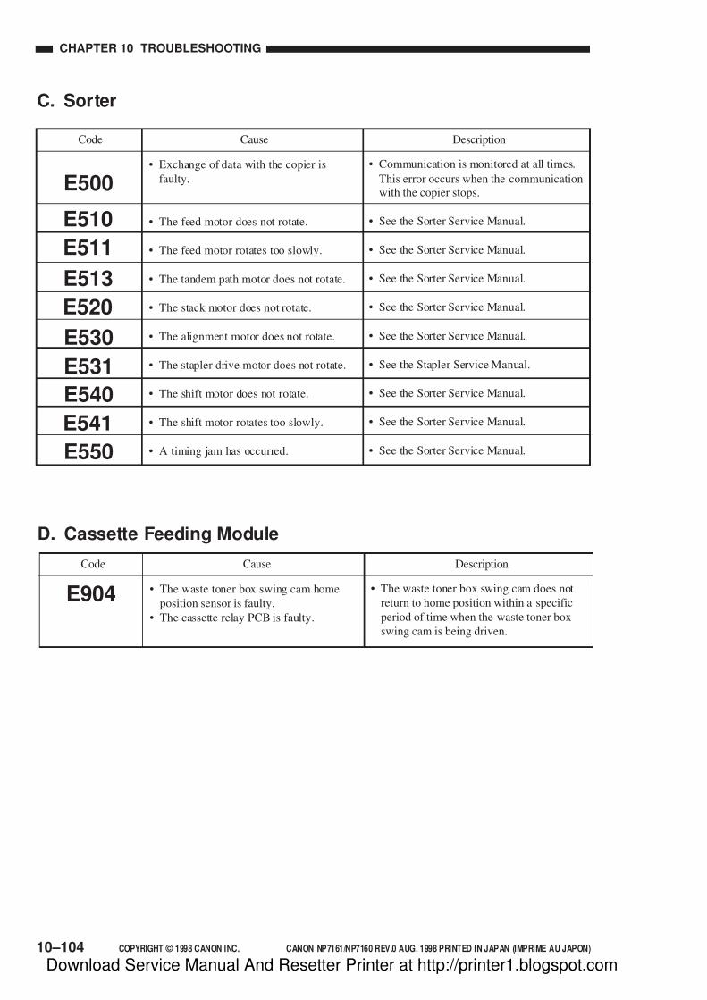
7/16/2019 Canon Np7161-Np7160 Copier Sm
http://slidepdf.com/reader/full/canon-np7161-np7160-copier-sm 334/345
10–104 COPYRIGHT © 1998 CANON INC. CANON NP7161/NP7160 REV.0 AUG. 1998 PRINTED IN JAPAN (IMPRIME AU JAPON)
CHAPTER 10 TROUBLESHOOTING
C. Sorter
• Exchange of data with the copier is
faulty.
• The feed motor does not rotate.
• The feed motor rotates too slowly.
• The tandem path motor does not rotate.
• The stack motor does not rotate.
• The alignment motor does not rotate.
• The stapler drive motor does not rotate.
• The shift motor does not rotate.
• The shift motor rotates too slowly.
• A timing jam has occurred.
• Communication is monitored at all times.
This error occurs when the communication
with the copier stops.
• See the Sorter Service Manual.
• See the Sorter Service Manual.
• See the Sorter Service Manual.
• See the Sorter Service Manual.
• See the Sorter Service Manual.
• See the Stapler Service Manual.
• See the Sorter Service Manual.
• See the Sorter Service Manual.
• See the Sorter Service Manual.E550
E541
E531
E530
E540
E510
E511
E513
E520
E500
Code Cause Description
D. Cassette Feeding Module
• The waste toner box swing cam home
position sensor is faulty.
• The cassette relay PCB is faulty.
• The waste toner box swing cam does not
return to home position within a specific
period of time when the waste toner box
swing cam is being driven.
E904
Code Cause Description
Download Service Manual And Resetter Printer at http://printer1.blogspot.com

7/16/2019 Canon Np7161-Np7160 Copier Sm
http://slidepdf.com/reader/full/canon-np7161-np7160-copier-sm 335/345
COPYRIGHT © 1998 CANON INC. CANON NP7161/NP7160 REV.0 AUG. 1998 PRINTED IN JAPAN (IMPRIME AU JAPON)
APPENDIX
A. GENERAL TIMING CHART ................ A-1B. SIGNALS AND ABBREVIATIONS ......A-2C. GENERAL CIRCUIT DIAGRAM .......... A-5
D. SPECIAL TOOLS LIST........................A-7E. SOLVENTS AND OILS ........................ A-8
Download Service Manual And Resetter Printer at http://printer1.blogspot.com

7/16/2019 Canon Np7161-Np7160 Copier Sm
http://slidepdf.com/reader/full/canon-np7161-np7160-copier-sm 336/345
Download Service Manual And Resetter Printer at http://printer1.blogspot.com
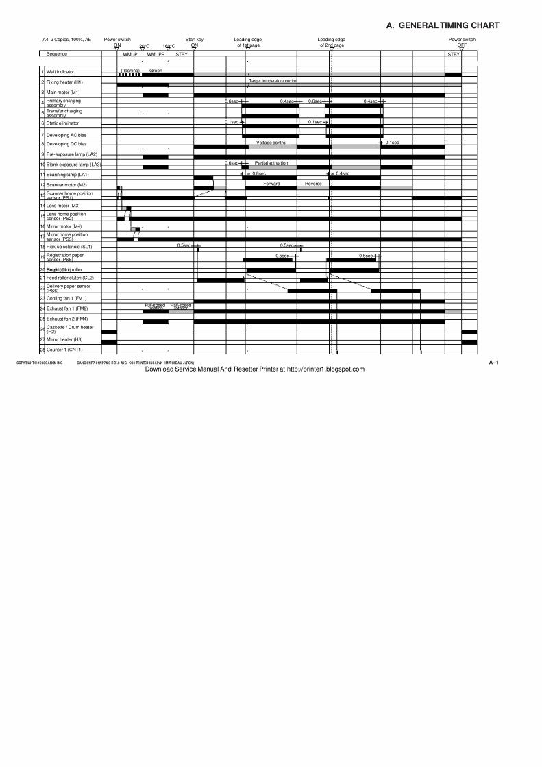
7/16/2019 Canon Np7161-Np7160 Copier Sm
http://slidepdf.com/reader/full/canon-np7161-np7160-copier-sm 337/345
COPYRIGHT © 1998 CANON INC. CANON NP7161/NP7160 REV.0 AUG. 1998 PRINTED IN JAPAN (IMPRIME AU JAPON) A–1
A. GENERAL TIMING CHART
Power switchON
Start keyON
Leading edgeof 1st page160°C120°C
Power switchOFF
Wait indicator
Main motor (M1)
Pre-exposure lamp (LA2)
Fixing heater (H1)
Primary chargingassembly
Transfer chargingassembly
Developing AC bias
Static eliminator
Developing DC bias
Scanning lamp (LA1)
Scanner home positionsensor (PS1)
Mirror home positionsensor (PS3)
Scanner motor (M2)
Mirror motor (M4)
Lens home positionsensor (PS2)
Lens motor (M3)
Blank exposure lamp (LA3)
Pick-up solenoid (SL1)
Feed roller clutch (CL2)
Registration papersensor (PS5)
Registration rollerclutch (CL1)
Delivery paper sensor(PS6)
Cooling fan 1 (FM1)
Exhaust fan 1 (FM2)
Exhaust fan 2 (FM4)
Cassette / Drum heater(H2)
Mirror heater (H3)
Counter 1 (CNT1)
WMUP WMUPR STBY STBY
Target temperature control
Voltage control
Partial activation
Green(flashing)
Full-speedrotation
Half-speedrotation
A4, 2 Copies, 100%, AE
Forward Reverse
0.4sec
Leading edgeof 2nd page
0.1sec
0.8sec
0.5sec 0.5sec
0.4sec
0.5sec 0.5sec
Sequence
1
2
3
4
5
6
7
8
9
10
11
12
13
14
15
16
17
18
19
20
21
22
23
24
25
26
27
28
0.6sec
0.1sec
0.4sec0.6sec
0.1sec
0.6sec
Download Service Manual And Resetter Printer at http://printer1.blogspot.com
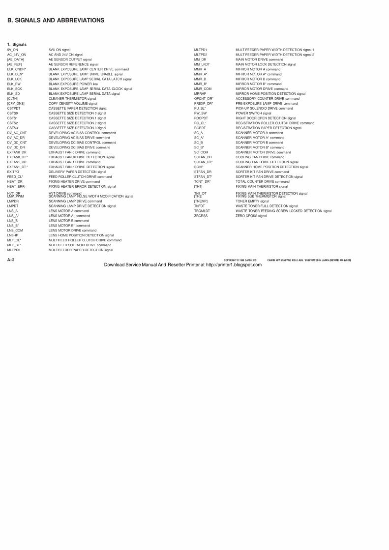
7/16/2019 Canon Np7161-Np7160 Copier Sm
http://slidepdf.com/reader/full/canon-np7161-np7160-copier-sm 338/345
COPYRIGHT © 1998 CANON INC. CANON NP7161/NP7160 REV.0 AUG. 1998 PRINTED IN JAPAN (IMPRIME AU JAPON)A–2
B. SIGNALS AND ABBREVIATIONS
1. Signals
5V_ON 5VU ON signal
AC_24V_ON AC AND 24V ON signal
[AE_DATA] AE SENSOR OUTPUT signal
[AE_REF] AE SENSOR REFERENCE signal
BLK_CNDR* BLANK EXPOSURE LAMP CENTER DRIVE command
BLK_DEN* BLANK EXPOSURE LAMP DRIVE ENABLE signal
BLK_LCK BLANK EXPOSURE LAMP SERIAL DATA LATCH signal
BLK_PW BLANK EXPOSURE POWER line
BLK_SCK BLANK EXPOSURE LAMP SERIAL DATA CLOCK signal
BLK_SD BLANK EXPOSURE LAMP SERIAL DATA signal
[CLTH] CLEANER THERMISTOR signal
[CPY_DNS] COPY DENSITY VOLUME signal
CSTPDT CASSETTE PAPER DETECTION signal
CSTS0 CASSETTE SIZE DETECTION 0 signal
CSTS1 CASSETTE SIZE DETECTION 1 signal
CSTS2 CASSETTE SIZE DETECTION 2 signal
CSTS3 CASSETTE SIZE DETECTION 3 signal
DV_AC_CNT DEVELOPING AC BIAS CONTROL command
DV_AC_DR DEVELOPING AC BIAS DRIVE command
DV_DC_CNT DEVELOPING DC BIAS CONTROL command
DV_DC_DR DEVELOPING DC BIAS DRIVE command
EXFAN0_DR EXHAUST FAN 0 DRIVE command
EXFAN0_DT * EXHAUST FAN 0 DRIVE DET ECTION signal
EXFAN1_DR EXHAUST FAN 1 DRIVE command
EXFAN1_DT * EXHAUST FAN 1 DRIVE DET ECTION signal
EXITPD DELIVERY PAPER DETECTION signal
FEED_CL* FEED ROLLER CLUTCH DRIVE command
HEAT_DR FIXING HEATER DRIVE command
HEAT_ERR FIXING HEATER ERROR DETECTION signal
HVT_DR HVT DRIVE commandLMP_PWM SCANNING LAMP PULSE WIDTH MODIFICATION signal
LMPDR SCANNING LAMP DRIVE command
LMPDT SCANNING LAMP DRIVE DETECTION signal
LNS_A LENS MOTOR A command
LNS_A* LENS MOTOR A* command
LNS_B LENS MOTOR B command
LNS_B* LENS MOTOR B* command
LNS_COM LENS MOTOR DRIVE command
LNSHP LENS HOME POSITION DETECTION signal
MLT_CL* MULTIFEED ROLLER CLUTCH DRIVE command
MLT_SL* MULTIFEED SOLENOID DRIVE command
MLTPD0 MULTIFEEDER PAPER DETECTION signal
MLTPD1 MULTIFEEDER PAPER WIDTH DETECTION signal 1
MLTPD2 MULTIFEEDER PAPER WIDTH DETECTION signal 2
MM_DR MAIN MOTOR DRIVE command
MM_LKDT MAIN MOTOR LOCK DETECTION signal
MMR_A MIRROR MOTOR A command
MMR_A* MIRROR MOTOR A* command
MMR_B MIRROR MOTOR B command
MMR_B* MIRROR MOTOR B* command
MMR_COM MIRROR MOTOR DRIVE command
MRRHP MIRROR HOME POSITION DETECTION signal
OPCNT_DR* ACCESSORY COUNTER DRIVE command
PREXP_DR* PRE-EXPOSURE LAMP DRIVE command
PU_SL* PICK-UP SOLENOID DRIVE command
PW_SW POWER SWITCH signal
RDOPDT RIGHT DOOR OPEN DETECTION signal
RG_CL* REGISTRATION ROLLER CLUTCH DRIVE command
RGPDT REGISTRATION PAPER DETECTION signal
SC_A SCANNER MOTOR A command
SC_A* SCANNER MOTOR A* command
SC_B SCANNER MOTOR B command
SC_B* SCANNER MOTOR B* command
SC_COM SCANNER MOTOR DRIVE command
SCFAN_DR COOLING FAN DRIVE command
SCFAN_DT* COOLING FAN DRIVE DETECTION signal
SCHP SCANNER HOME POSITION DETECTION signal
STFAN_DR SORTER KIT FAN DRIVE command
STFAN_DT* SORTER KIT FAN DRIVE DETECTION signal
TCNT_DR* TOTAL COUNTER DRIVE command
[TH1] FIXING MAIN THERMISTOR signal
TH1_DT FIXING MAIN THERMISTOR DETECTION signal[TH2] FIXING SUB THERMISTOR signal
[TNEMP] TONER EMPTY signal
TNFDT WASTE TONER FULL DETECTION signal
TRQMLDT WASTE TONER FEEDING SCREW LOCKED DETECTION signal
ZRCRSS ZERO CROSS signal
Download Service Manual And Resetter Printer at http://printer1.blogspot.com

7/16/2019 Canon Np7161-Np7160 Copier Sm
http://slidepdf.com/reader/full/canon-np7161-np7160-copier-sm 339/345
COPYRIGHT © 1998 CANON INC. CANON NP7161/NP7160 REV.0 AUG. 1998 PRINTED IN JAPAN (IMPRIME AU JAPON)
AER AE ROTATION
INTR INITIAL ROTATION
LSTR LAST ROTATION
SCFW SCANNER FORWARD
SCRV SCANNER REVERSE
STBY STANDBY
WMUP WARM-UP
WMUPR WARM-UP ROTATION
2. Abbreviations

7/16/2019 Canon Np7161-Np7160 Copier Sm
http://slidepdf.com/reader/full/canon-np7161-np7160-copier-sm 340/345
APPENDIX
A–4 COPYRIGHT © 1998 CANON INC. CANON NP7161/NP7160 REV.0 AUG. 1998 PRINTED IN JAPAN (IMPRIME AU JAPON)
Download Service Manual And Resetter Printer at http://printer1.blogspot.com
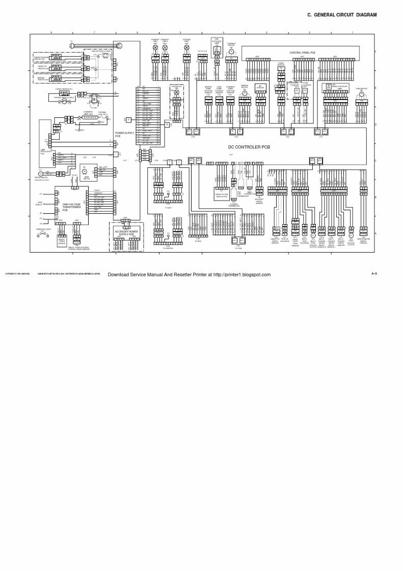
7/16/2019 Canon Np7161-Np7160 Copier Sm
http://slidepdf.com/reader/full/canon-np7161-np7160-copier-sm 341/345

7/16/2019 Canon Np7161-Np7160 Copier Sm
http://slidepdf.com/reader/full/canon-np7161-np7160-copier-sm 342/345
APPENDIX
A–6 COPYRIGHT © 1998 CANON INC. CANON NP7161/NP7160 REV.0 AUG. 1998 PRINTED IN JAPAN (IMPRIME AU JAPON)
Download Service Manual And Resetter Printer at http://printer1.blogspot.com

7/16/2019 Canon Np7161-Np7160 Copier Sm
http://slidepdf.com/reader/full/canon-np7161-np7160-copier-sm 343/345
APPENDIX
COPYRIGHT © 1998 CANON INC. CANON NP7161/NP7160 REV.0 AUG. 1998 PRINTED IN JAPAN (IMPRIME AU JAPON) A–7
D. SPECIAL TOOLS LIST
Frontdoor
Point of use
No. Tool description Tool No. Shape Notation Remarks
1 Door switch TKN-0093 A
2 Mirror positioning
tool
FY9-3009 B For adjusting the
No. 1/No. 2 mirror
position (front/rear
as a pair)
Download Service Manual And Resetter Printer at http://printer1.blogspot.com

7/16/2019 Canon Np7161-Np7160 Copier Sm
http://slidepdf.com/reader/full/canon-np7161-np7160-copier-sm 344/345
APPENDIX
A–8 COPYRIGHT © 1998 CANON INC. CANON NP7161/NP7160 REV.0 AUG. 1998 PRINTED IN JAPAN (IMPRIME AU JAPON)
E. SOLVENTS AND OILS
No. Description Use Composition Description
1 Ethyl alcohol
(Etanol)
Isopropyl
alcohol
(Isopropanol)
Cleaning:
e.g., glass,
plastic,
rubber parts;
external covers
C2H5O
(CHZ3)2 CHOH
• Do not bring near open fire.
• Procure locally.
• Isopropyl alcohol may be
substituted.
3 Heat-resisting
grease
Lubricating; e.g., fixing
drive assemblies
Lithium soap
(mineral oil family)
Moblybdenum bisulfide
• CK-0427 (500 g/can)
4 Lubricant oil
Lubricating:
scanner rail
Mineral oil
(paraffin family)
• CK-0451 (100 cc)
5 Lubricant oil Mineral oil
(paraffin family)
• CK-0524 (100 cc)
2 MEK Cleaning:
e.g., metal;
oil or toner
CH3COC2H5 • Do not bring near fire.
• Procure locally.
6 Lubricant oil Slicone oil • CK-0551 (20 g)
Download Service Manual And Resetter Printer at http://printer1.blogspot.com
7/16/2019 Canon Np7161-Np7160 Copier Sm
http://slidepdf.com/reader/full/canon-np7161-np7160-copier-sm 345/345
Prepared by
OFFICE IMAGING PRODUCTS TECHNICAL SUPPORT DEPT. 1
OFFICE IMAGING PRODUCTS TECHNICAL SUPPORT DIV.
CANON INC.
Printed in Japan
REVISION 0 (AUG. 1998) [23715]
5-1, Hakusan 7-chome, Toride-shi, Ibaraki 302-8501, Japan