Finite element analysis of actively controlled smart plate with ...

CanogaView® Smart Element Manager
i

CanogaView® Smart Element Manager
NOTICE
Canoga Perkins has prepared this users manual for use by customers and Canoga Perkins personnel as a guide for the proper installation, operation and/or maintenance of Canoga Perkins equipment. The drawings, specifications and information contained in this document are the property of Canoga Perkins and any unauthorized use or disclosure of the drawings, specifications and information is prohibited. Canoga Perkins reserves the right to change or update the contents of this manual and to change the specifications of its products at any time without prior notification. Every effort has been made to keep the information in this document current and accurate as of the date of publication or revision; however, no guarantee is given or implied that the document is error free or that it is accurate with regard to any specification.
CANOGA PERKINS CORPORATION An Inductotherm Company
20600 Prairie Street Chatsworth, California 91311-6008 Business Phone: (818) 718-6300
(Monday - Friday 7 a.m. - 5 p.m. Pacific Time) FAX: (818) 718-6312 (24 hrs.)
Web Site: www.canoga.com Email: [email protected]
Copyright© 2000 - 2003 Canoga Perkins Corporation All Rights Reserved
CanogaView Smart Element Manager
Enterprise Version
Part Number 6912640-000 Rev. H 01/2008
To reference Technical Advisories and Product Release Notes, go to Canoga Perkins' website: http://www.canoga.com
ii

CanogaView® Smart Element Manager
Table of Contents Chapter 1 System Requirements.........................................................................................1 1.1 Windows Platform Requirements ................................................................................1 1.1.1 Windows Minimum Hardware Requirements ...........................................................1 1.1.2 Windows Minimum Software Requirements.............................................................1 1.2 Solaris Platform Requirements....................................................................................1 1.2.1 Solaris Minimum Hardware Requirements...............................................................1 1.2.2 Solaris Minimum Software Requirements ................................................................2 1.3 HP-UX Platform Requirements ...................................................................................2 1.3.1 HP-UX Minimum Hardware Requirements...............................................................2 1.3.2 HP-UX Minimum Software Requirements ................................................................2 1.4 SNMP Agent Requirements ........................................................................................2 Chapter 2 Installing CanogaView Smart Element Manager ..............................................7 2.1 Installation Process .....................................................................................................7 2.2 Installation Steps .........................................................................................................7 2.2.1 Insert CD ..................................................................................................................7 2.2.2 Product Splash Display ............................................................................................9 2.2.3 Installation Introduction ..........................................................................................10 2.2.4 License Agreement ................................................................................................10 2.2.5 Important Information .............................................................................................12 2.2.6 Choose Install Folder .............................................................................................13 2.2.7 Choose Shortcut Location ......................................................................................13 2.2.8 Choose Link Location.............................................................................................14 2.2.9 Select Install Set.....................................................................................................15 2.2.10 Enter SNMP Trap Port ...........................................................................................16 2.2.11 Enter CanogaView Server Host .............................................................................17 2.2.12 NNM Integration .....................................................................................................19 2.2.13 Pre-Installation Summary .......................................................................................19 2.2.14 Installation Billboards .............................................................................................21 2.2.17 Installation Complete..............................................................................................22 2.3 Post Installation Steps...............................................................................................22 2.3.1 HP OpenView URL Setup for SNMP Agents .........................................................22 2.3.2 Netscape Navigator Environment Variable (Unix only) ..........................................23 2.3.3 Delete Directories if Desired (Unix only) ................................................................24 Chapter 3 Using CanogaView Smart Element Manager ..................................................25 3.1 User Interface Overview............................................................................................25 3.1.1 Application Overview..............................................................................................25 3.1.2 Menus and Toolbars...............................................................................................29 3.1.3 License Restrictions ...............................................................................................30 3.2 Getting Started ..........................................................................................................32 3.2.1 Opening CanogaView Smart Element Manager ....................................................32 3.2.2 Start CanogaView Smart Element Manager ..........................................................33 3.2.3 Login.......................................................................................................................35 3.2.4 Agent Chooser .......................................................................................................35 3.2.5 Views......................................................................................................................38 3.3 Other Applications .....................................................................................................44 3.3.1 Account Manager ...................................................................................................44 3.3.2 Alarm Monitor .........................................................................................................46 3.3.3 Configuration ..........................................................................................................51
iii

CanogaView® Smart Element Manager
3.3.4 Reset ......................................................................................................................52 3.3.5 Reports...................................................................................................................54 3.3.6 Security Manager ...................................................................................................58 3.3.7 Status .....................................................................................................................60 3.3.8 Telnet .....................................................................................................................64 3.3.9 TFTP Server...........................................................................................................65 Chapter 4 Frequently Asked Questions............................................................................67 4.1 What Web Server Platforms are supported?.............................................................67 4.2 What Web Client Platforms are supported? ..............................................................67 4.3 What Web Server is used by CanogaView Smart Element Manager? .....................67 4.4 What is a Java Plug-In or Java Runtime Environment? ............................................67 4.5 How many Web Clients are supported?....................................................................67 4.6 How many User Accounts are supported?................................................................68 4.7 How do I Install CanogaView Smart Element Manager? ..........................................68 4.8 How do I Uninstall CanogaView Smart Element Manager? ......................................68 4.9 How do I Login? ........................................................................................................68 4.10 Why doesn't CanogaView Smart Element Manager support Netscape 6.0? ............68 4.11 What Version of HP OpenView can CanogaView Smart Element Manager be integrated with?.....................................................................................................................69 4.12 What does CanogaView Smart Element Manager actually do?................................69 4.13 Which Canoga Perkin's Products does CanogaView Smart Element Manager manage? ...............................................................................................................................69 4.14 What versions of the products must be installed?.....................................................69 4.15 What is a Domain? ....................................................................................................69 4.16 How are Remote Products managed? ......................................................................70 4.17 What Security Levels does CanogaView Smart Element Manager support? ...........70 Chapter 5 Troubleshooting ................................................................................................71 5.1 No Response from SNMP Agent...............................................................................71 5.2 "Model Not Found" image appears on my View........................................................71 5.3 Traps/Alarm Processing ............................................................................................72 Appendix A Warranty Information................................................................................... A-1
iv

CanogaView® Smart Element Manager
List of Figures Figure 1-1: DMM Host Table.................................................................................................3 Figure 1-2: 9135 Host Table .................................................................................................4 Figure 1-3: SNMP Agent Chooser showing Edit Window .................................................5 Figure 2-1: Product Splash Display.....................................................................................9 Figure 2-2: Installation Introduction..................................................................................10 Figure 2-3: License Agreement..........................................................................................11 Figure 2-4: Important Information .....................................................................................12 Figure 2-5: Choose Install Folder ......................................................................................13 Figure 2-6. Choose Shortcut Location ..............................................................................14 Figure 2-7. Choose Link Location. ...................................................................................15 Figure 2-8. Choose Install Set...........................................................................................16 Figure 2-9: Enter SNMP Trap Port ....................................................................................17 Figure 2-10: Enter Web Server HTTP Port .......................................................................18 Figure 2-11: NNM Integration ............................................................................................19 Figure 2-12: Pre-Installation Summary ............................................................................20 Figure 2-13: Billboard Example .........................................................................................21 Figure 2-14: Installation Complete ....................................................................................22 Figure 3-1. Starting Point ...................................................................................................26 Figure 3-2. Agent Chooser Toolbar ...................................................................................29 Figure 3-3. Domain View Toolbar ......................................................................................29 Figure 3-4. Device View Toolbar ........................................................................................29 Figure 3-5. Too many users ...............................................................................................31 Figure 3-6. Shortcut Menu..................................................................................................32 Figure 3-7. IE Address Field Example ...............................................................................33 Figure 3-8. CanogaView Start Page...................................................................................34 Figure 3-9. Login Screen ....................................................................................................35 Figure 3-10: SNMP Agent Chooser....................................................................................36 Figure 3-11. Add/Edit Agent Screen ..................................................................................37 Figure 3-12. Agent Chooser Status Example ...................................................................38 Figure 3-13. Selectable Views ............................................................................................39 Figure 3-14. Domain View...................................................................................................40 Figure 3-15. Chassis View. .................................................................................................41 Figure 3-16. Modem View. ..................................................................................................42 Figure 3-17. 9135G View .....................................................................................................43 Figure 3-18. 9135G Port View.............................................................................................43 Figure 3-19: Account Manager...........................................................................................45 Figure 3-20: Add User.........................................................................................................45 Figure 3-21. Alarm Monitor – All Alarms Filter .................................................................47 Figure 3-23. Alarm Legend .................................................................................................49 Figure 3-24. Alarm Event Queries......................................................................................50
v

CanogaView® Smart Element Manager
vi
Figure 3-25. Alarms Records by Log Time Input .............................................................50 Figure 3-26. Example Alarm Report ..................................................................................51 Figure 3-27. 9135G Port Configuration .............................................................................52 Figure 3-28. Fiber Optic Modem Reset Example..............................................................53 Figure 3-29. 9135G Reset Example....................................................................................53 Figure 3-30. Factory Defaults Confirmation Example......................................................54 Figure 3-31. Reset Confirmation Example ........................................................................54 Figure 3-32. Domain Level Reports ...................................................................................55 Figure 3-33. Domain Level Report Example .....................................................................56 Figure 3-34. 9135G Report..................................................................................................57 Figure 3-35. Security Manager ...........................................................................................59 Figure 3-36. Chassis Status ...............................................................................................60 Figure 3-37. 9135G Status – General Tab .........................................................................61 Figure 3-38. 9135G Status – Spanning Tree Tab..............................................................62 Figure 3-39. 9135G Status – Forwarding Database Tab ..................................................63 Figure 3-40. 9135G Status – Version Tab..........................................................................63 Figure 3-41. 9135G Port Statistics .....................................................................................64 Figure 3-42. DMM Telnet Example .....................................................................................65 Figure 3-43. TFTP Server Utility.........................................................................................66 Figure 3-44. TFTP Help .......................................................................................................66

CanogaView® Smart Element Manager
Chapter 1 System Requirements The CanogaView Smart Element Manager Server’s hardware and software minimum requirements as well as the SNMP Agent requirements are listed in this section of the manual. CanogaView Smart Element Manager installation support exists for Windows, Solaris and HP-UX platforms. The Enterprise Version of CanogaView Smart Element Manager is installed with a restricted one (1) seat license which limits its use to only one active login session at a time. Upgrade options for ten (10) seat and unlimited seat licensing are available. 1.1 Windows Platform Requirements 1.1.1 Windows Minimum Hardware Requirements
• Intel Pentium 500MHz Processor (1GHz or higher is strongly recommended) • 128MB RAM (256MB or higher is strongly recommended) • 200MB free disk space for application space • 300MB free disk space of tmp space during the installation process • SVGA Monitor with 256 colors and 1024x768 resolution will display but the quality
will be extremely poor. It is strongly recommended that 65536 colors (16 bit) or higher be used.
• Network Adapter Card is required for Ethernet LAN support 1.1.2 Windows Minimum Software Requirements
• Microsoft Windows OS with TCP/IP Services: • Windows NT 4.0 SP4 -or- • Windows 2000 -or- • Windows XP
• Web Browser supporting Java Plug-In: • Netscape Navigator 4.06 or later –or- • Microsoft Internet Explorer 4.0 or later
• Java Plug-In 1.3.0_01 or later • HP OpenView Network Node Manager 6.1 (optional)
1.2 Solaris Platform Requirements 1.2.1 Solaris Minimum Hardware Requirements
• Sun SparcStation • 128MB RAM (256MB is recommended) • 200MB free disk space for application space • 300MB free disk space of tmp space during the installation process • CD-ROM Drive
Enterprise Version 1

CanogaView® Smart Element Manager
1.2.2 Solaris Minimum Software Requirements • Sun Solaris OS Version 7 (a.k.a. Solaris 2.7, SunOS 5.7) • Web Browser supporting Java Plug-In:
• Netscape Navigator 4.76 or later • Java plug-In 1.3.0_01 or later • HP OpenView Network Node Manager 6.1 (optional)
1.3 HP-UX Platform Requirements 1.3.1 HP-UX Minimum Hardware Requirements
• HP 9000 workstation, Series 700 or 800 • 128MB RAM (256MB is recommended) • 200MB free disk space for application space • 300MB free disk space of tmp space during the installation process • CD-ROM Drive
1.3.2 HP-UX Minimum Software Requirements
• HP-UX version 11.0 • Web Browser supporting Java Plug-In:
• Netscape Navigator 4.75 • Java plug-In 1.3.0 • HP OpenView Network Node Manager 6.1 (optional)
1.4 SNMP Agent Requirements The IP address of the server on which the CanogaView Smart Element Manager Enterprise software is installed must be added to the SNMP Agent’s host table for each device that is to be managed. Additionally, if trap/alarm monitoring is desired, then the appropriate “access level” and “trap port” must be setup. The SNMP Agents currently supported are:
• Domain Management Module (DMM) for management support of the Universal Chassis System (up to eight 2U and 5U chassis per DMM) and its components.
• 9135 Two Port EdgeAccess™ Switch - 100BASE-TX/FX Compliant Fast Ethernet device with the SNMP Management Module.
• 9140 Four Port EdgeAccess™ Switch - 100BASE-TX/FX Compliant Fast Ethernet device with the SNMP Management Module.
• 9135G Gigabit Two-port EdgeAccess™ Switch is a IEEE compliant Ethernet device with SNMP Management Module.
• 9135E 10/100/1000 MBPS Two-port EdgeAccess™ Switch is a 1000BASE-LX compliant Ethernet device with SNMP Management Module.
• UCS 1020 one slot enclosure to provide SNMP Management access to any Canoga Perkins fully manageable 2U Module (L311, L321, L331, L351, 2346, 2446, …)
Enterprise Version 2

CanogaView® Smart Element Manager
It is important that the software (aka firmware) installed on any of the SNMP Agents listed above, be at the required level in order for CanogaView Smart Element Manager to correctly access the essential management data residing at the network element level. An example telnet session screen showing the DMM Host Table is shown below:
Figure 1-1: DMM Host Table
Enterprise Version 3

CanogaView® Smart Element Manager
An example of a 9135 Host Table telnet session screen is shown below: (the screens for the 9140 and 9135G products are very similar to that of the 9135)
Figure 1-2: 9135 Host Table
Enterprise Version 4

CanogaView® Smart Element Manager
Enterprise Version 5
In addition, the CanogaView Smart Element Manager’s SNMP Agent Chooser application must be used to add each managed SNMP Agent to its database. CanogaView Smart Element Manager must know the IP Address and Agent Type of the SNMP Agent so that the correct management applications are used to access and retrieve data from the managed device using the SNMP protocol and device relevant MIB variables.
Figure 1-3: SNMP Agent Chooser showing Edit Window


CanogaView® Smart Element Manager
Chapter 2 Installing CanogaView Smart Element Manager All files necessary for the installation of the CanogaView Smart Element Manager software are contained on the installation CD. Additionally, this manual as well as other technical information is also contained on the CD and installed with the software. 2.1 Installation Process The following steps assume that the CanogaView Smart Element Manager software is being installed via the installation CD. If the software has been downloaded from Canoga Perkin’s corporate web site, then locate the “install.htm” file at the top of the downloaded directory tree and select/execute it. If you install CanogaView onto a computer running Network Node Manager (NNM) and you select the option to integrate with NNM, the NNM services must be running. Additionally, if the NNM user interface is running, ensure that the Event Configuration application is not displayed. You will be reminded of this during the installation. Note: The actual install process will vary slightly depending upon the hardware platform, operating system software and the response to installer prompts. Not all of the installer steps described appear during installation. The installation screen examples shown in this manual are from a Windows NT installation with HP OpenView NNM also installed. 2.2 Installation Steps 2.2.1 Insert CD Windows Platforms
Insert the CD into the CD-ROM drive. If the installer web page did not automatically display when the CD was inserted into the CD-ROM drive, locate the file install.htm and double click on it or open it with your browser (File >> Open or File >> Open Page). Read the installation instructions and then proceed to the next step. The next step in the installation process is basically to locate and execute the installation procedure which is on the CD. This can be done by selecting (clicking) on this install link, or by locating the InstData/Windows/Vm directory on the CD ROM and executing the file install.exe. Next proceed to section 2.2.2.
Solaris Platform
Enterprise Version 7
CanogaView® Smart Element Manager
Insert the CD into the CD-ROM drive. Mount the CD via the command:
cd /cdrom/cdrom0
If this command fails, wait a few moments and try again (it may take a short time for the CD-ROM to be detected).
Locate the file install.htm and open it with your browser (File >> Open Page). A browser page will open with the CanogaView Smart Element Manager image displayed. Read the installation instructions and proceed to the next step. The next in the installation process is basically to locate and execute the installation procedure which is on the CD. Locate the InstData/Solaris/Vm directory on the CD ROM and executing the file install.bin. Next proceed to section 2.2.2.
HP-UX Platform
Installation on HP-UX requires that the Portable File System (PFS) processes pfs_mountd and pfsd be running. Determine if they are running by executing the command:
ps -e | grep pfs If this command returns no output, start the PFS processes via these commands:
nohup /usr/sbin/pfs_mountd & nohup /usr/sbin/pfsd &
Insert the CD into the CD-ROM drive. If the directory /cdrom does not exist on your workstation, create it now:
mkdir /cdrom Mount the CD via the command:
/usr/sbin/pfs_mount -t rrip /dev/rdsk/c0t0d0 /cdrom Substitute the device name of your CD-ROM drive for /dev/rdsk/c0t0d0 if necessary (command “ioscan -fnC disk” will display your CD-ROM device name).
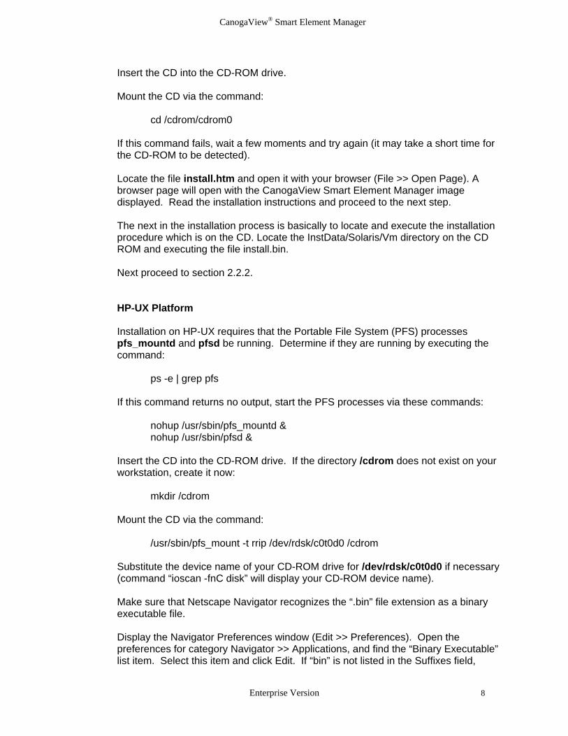
Make sure that Netscape Navigator recognizes the “.bin” file extension as a binary executable file. Display the Navigator Preferences window (Edit >> Preferences). Open the preferences for category Navigator >> Applications, and find the “Binary Executable” list item. Select this item and click Edit. If “bin” is not listed in the Suffixes field,
Enterprise Version 8

CanogaView® Smart Element Manager
append it to the current value of Suffixes and save the change (use a comma to separate suffix values (e.g. “uu,bin”)). Locate the file install.htm and open it with your browser (File >> Open Page). A browser page will open with the CanogaView Smart Element Manager image displayed. Read the installation instructions and then proceed to the next step. The next in the installation process is basically to locate and execute the installation procedure which is on the CD. Locate the InstData/Hpux/Vm directory on the CD ROM and executing the file install.bin. Proceed to section 2.2.2 below.
2.2.2 Product Splash Display Once extracted, the installation process will display the CanogaView Smart Element Manager product splash window that follows:
Figure 2-1: Product Splash Display
Enterprise Version 9

CanogaView® Smart Element Manager
2.2.3 Installation Introduction The installation software displays an Introduction screen.
Figure 2-2: Installation Introduction 2.2.4 License Agreement Next, the Canoga Perkin’s License agreement is displayed. You must “accept” the terms of the license agreement in order to continue with the installation process.
Enterprise Version 10

CanogaView® Smart Element Manager
Figure 2-3: License Agreement
Enterprise Version 11

CanogaView® Smart Element Manager
2.2.5 Important Information Next, the Important Information screen is displayed. It is important that you meet the minimum hardware and software system requirements in order to continue with the installation process.
Figure 2-4: Important Information
Enterprise Version 12

CanogaView® Smart Element Manager
2.2.6 Choose Install Folder The first configurable installation screen that you will encounter is the "Choose Install Folder" screen. Canoga Perkins suggests that you select the default installation location if possible. If you are not sure seek the advice of your IT Administrator.
Figure 2-5: Choose Install Folder
2.2.7 Choose Shortcut Location This screen appears only during installation on a Windows platform. The "Choose Shortcut Location" screen defines where application shortcuts will be placed. • In a new program group - Program groups are folders in a user profile that appear under
the menu: Start -> Programs. This option inserts the shortcuts into a new program group that the installer defines.
• In an existing program group - This option inserts the shortcuts into a program group that already exists.
• In the Start Menu - This option inserts the shortcuts into the Windows Start menu. • On the Desktop - This option creates shortcut icons on the desktop. • Other: select location - The user selects a location in which to insert the shortcuts. • Do not create shortcut icons - No shortcut icons will be created.
Enterprise Version 13

CanogaView® Smart Element Manager
Figure 2-6. Choose Shortcut Location When CanogaView software is installed on a Windows platform, five shortcuts will be created on the system under “Start Menu CanogaView Smart Element Manager ”
• Account Manager - manages CanogaView accounts and establishes new users • Canoga Perkins Website - link to Canoga Perkins' web page • Security Manager - manages CanogaView application security • Start CanogaView Smart Element Manager - opens the Start Page • TFTP Server – executes the TFTP server application which supports firmware upgrades
in Canoga Perkins devices 2.2.8 Choose Link Location This screen appears only during installation on a Unix platform. The "Choose Link Location" screen defines where symbolic links created by the installer are to be placed. • In your home folder - This option creates symbolic links in the logged in user's home
directory. • Other: select location - Specify a location in which to create symbolic links. • Don't create links: No symbolic links will be created.
Enterprise Version 14

CanogaView® Smart Element Manager
Figure 2-7. Choose Link Location. Note: Dependant upon the installation options, the installer may not create links at all. 2.2.9 Select Install Set This screen appears only when Network Node Manager (NNM) software is detected on the target computer. The "Select Installation Type" screen allows you to indicate how CanogaView Smart Element Manager should be installed and configured in relation to Network Node Manager (NNM). • Standalone - This option installs CanogaView software on the target computer such that
it is completely independent of NNM. No NNM customization for Canoga Perkins devices or CanogaView access is performed.
• Integrated with NNM - This option installs CanogaView software on the target computer. NNM is customized for Canoga Perkins devices (e.g., custom symbols, event configurations, etc.) and for access to CanogaView via NNM map symbols.
• Custom – This option allows the installer to choose the features that they want installed. The options are explained in the description section on the screen.
Enterprise Version 15

CanogaView® Smart Element Manager
• Remote Access – This option sets up the Client computer with shortcuts and menu
options to access a CanogaView Server. • Remote Access fro… - This option does not install CanogaView software on the target
computer, but does customize NNM for Canoga Perkins devices and for access to CanogaView software installed on other computers.
Figure 2-8. Choose Install Set 2.2.10 Enter SNMP Trap Port The "Enter SNMP Trap Port" screen allows the selection of a port number on which the CanogaView Trap Service should listen for SNMP traps. The default port for this installation is 163 and as explained on the installation screen, unless other network management software uses this port, the default port should be selected.
Enterprise Version 16

CanogaView® Smart Element Manager
Figure 2-9: Enter SNMP Trap Port
2.2.11 Enter CanogaView Server Host This screen will appear only when installing on a Windows platform with the "NNM Setup for Remote CanogaView Access" installation type selected. The "Enter CanogaView Server Host" screen allows a Domain Name Service (DNS) host name (or IP address) for a computer running CanogaView software to be entered. NNM will be configured to set the default management URL attribute of discovered Canoga Perkins devices to a CanogaView web page running on this host computer.
Enterprise Version 17

CanogaView® Smart Element Manager
Figure 2-10: Enter Web Server HTTP Port
Enterprise Version 18
CanogaView® Smart Element Manager
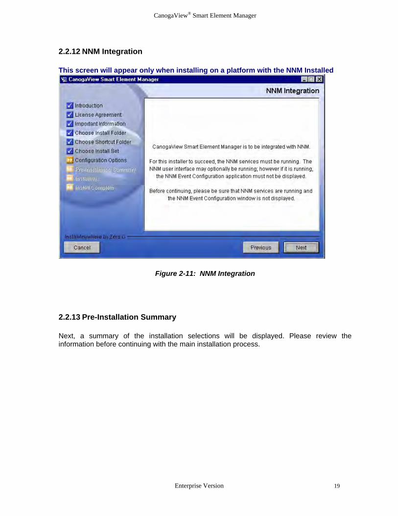
2.2.12 NNM Integration This screen will appear only when installing on a platform with the NNM Installed
Figure 2-11: NNM Integration 2.2.13 Pre-Installation Summary Next, a summary of the installation selections will be displayed. Please review the information before continuing with the main installation process.
Enterprise Version 19
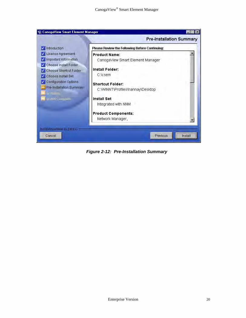
CanogaView® Smart Element Manager
Figure 2-12: Pre-Installation Summary
Enterprise Version 20
CanogaView® Smart Element Manager
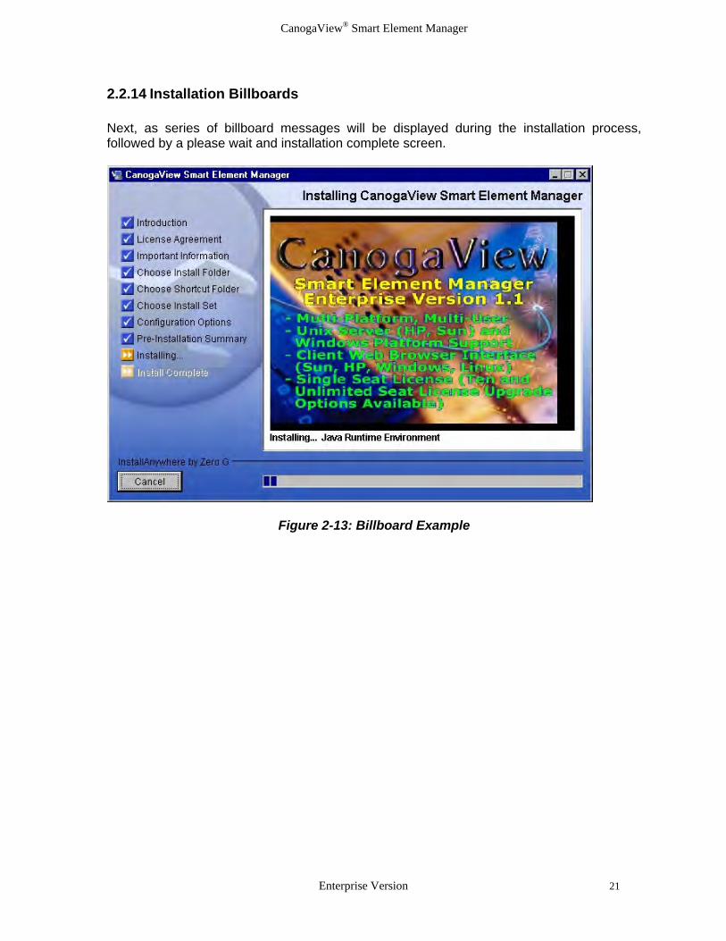
2.2.14 Installation Billboards Next, as series of billboard messages will be displayed during the installation process, followed by a please wait and installation complete screen.
Figure 2-13: Billboard Example
Enterprise Version 21

CanogaView® Smart Element Manager
2.2.17 Installation Complete
Figure 2-14: Installation Complete 2.3 Post Installation Steps 2.3.1 HP OpenView URL Setup for SNMP Agents This step is required for installations with HP OpenView NNM Integration only. Unix Specific Instructions (HP-UX and Sun)
Unix versions of NNM do not support the setting of the management URLs during an installation procedures as done for the Windows version. Therefore the “Setting Management URLs Manually” section (follows the next section) must be followed. The set the management URL must be specified to be able to access a SNMP Agent’s View from the NNM web interface.
Windows Specific Instructions
When integrating with HP’s Windows version of NNM, CanogaView Smart Element Manager configures NNM to set the Management URL attribute for the Canoga Perkins’ SNMP managed devices; DMM for 2U and 5U chassis based products, 9135 related devices and any of the managed devices residing in a standalone
Enterprise Version 22

CanogaView® Smart Element Manager
device (eg. 1020, 1040, etc.). If for any reason this setting is unsuccessful, the manual setting of such is required. The setting of the management URL must be specified to be able to access an SNMP Agent’s View from the NNM web interface. If a SNMP Agent's Management URL attribute does not get set properly, try adjusting the NNM configuration change polling interval. This interval is accessed via the NNM dialog: Options->Network Polling Configuration:IP/IPX Make sure "Perform configuration checks" is checked. The value for "Configuration polling interval" is the maximum length of time it should take for NNM to set the Management URL for SNMP Agent(s) after installing CanogaView Smart Element Manager. Since the default interval is one day, you may want to adjust this to a shorter interval, at least temporarily. Note that these two parameters are also used by the NNM netmon process. If the Management URL still does not get set properly, it may be configured manually as documented below.
Setting Management URLs Manually 1. Select a DMM, 9135/40 or 9135G symbol on a NNM submap. 2. Select "Object Properties" on the Edit menu. 3. Double-click on "General Attributes". 4. Set attribute "isHTTPManaged" to "True". 5. Set attribute "ManagementURL" to one of the following depending on the SNMP Agent
type:
DMM "http://nms_server_host:8080/nms/jsp/DomainView.jsp?IP_CONTEXT=agent_ip_addr" 9135 "http://nms_server_host:8080/nms/jsp/Dev91xxView.jsp?IP_CONTEXT=agent_ip_addr" 9135G "http://nms_server_host:8080/nms/jsp/Dev91xxgView.jsp?IP_CONTEXT=agent_ip_addr" 9140 "http://nms_server_host:8080/nms/jsp/Dev91xxView.jsp?IP_CONTEXT=agent_ip_addr"
Notes:
1. These are case sensitive. 2. Replace "nms_server_host" with the hostname or IP address of the server on which you
installed the CanogaView Smart Element Manager software. 3. Replace "agent_ip_addr" with the SNMP Agent's IP address.
2.3.2 Netscape Navigator Environment Variable (Unix only) This step is required for UNIX installations only. Starting with Netscape Navigator 4.0, it is strongly recommended that environment variable MOZILLA_HOME be exported and set to point to the Netscape installation directory. This can be accomplished with the Bourne and Korn shells, for example, with the commands: export MOZILLA_HOME
Enterprise Version 23

CanogaView® Smart Element Manager
Enterprise Version 24
MOZILLA_HOME=/path/to/Netscape/install/directory It is recommended that these commands be added to a file that is sourced automatically when the machine is booted or the user logs in (e.g. /.dtprofile for Common Desktop Environment (CDE)). 2.3.3 Delete Directories if Desired (Unix only) This step is for UNIX installations only. The IA_Installers and its contents are not needed after the installation completes; they may be safely deleted if desired. CanogaView Smart Element Manager installers create a directory named IA_Installers in the root directory (/) when run. This directory holds expanded installer files that are used during the course of the installation. If you experience problems installing which appear to be due to a lack ofspace in the root filesystem, work around the problem using a symbolic link.First delete the /IA_Installers directory, if present. Create a directoryin a filesystem with sufficient disk space, then create a symbolic linkin the root directory named "IA_Installers" to point to the new directory (e.g. "ln -s /some/new/dir /IA_Installers") and then attempt to reinstall CanogaView Smart Element Manager.

CanogaView® Smart Element Manager
Chapter 3 Using CanogaView Smart Element Manager This chapter provides an overview of the CanogaView Smart Element Manager’s user interface, a Getting Started section which lists the basic steps that one would follow to start managing their network including examples and a description of the miscellaneous applications. 3.1 User Interface Overview This section provides an overview of the graphical user interface applications and their usage. Included are:
• Application Overview • Menus and Toolbars • License Restrictions
3.1.1 Application Overview The CanogaView Smart Element Manager basically consists of client and server side services. The client side components consist of HTML web pages, Java scripts and Java applets that execute within a web browser that supports Java (typically Internet Explorer or Netscape). These web pages and applets communicate and are managed by CanogaView Smart Element Manager’s web server. The server side components are the web server, Java server pages (jsp), HTML pages, Java scripts, Java servlets, database and SNMP communication stack. The following table lists the client side services and the basic application hierarchy (who calls who as indicated using colors and indentations). It is assumed that the user is starting from the main start up page which is displayed here:
Enterprise Version 25

CanogaView® Smart Element Manager
Figure 3-1. Starting Point CanogaView Smart Element Manager Application Hierarchy
Notes
CanogaView Smart Element Manager Home Page Starting point for selection of underlying features using web browser application (IE, Netscape, …) http://localhost:8080/nms.html
Start Selects Login and Agent Chooser applet Agent Chooser SNMP Agent management application Add/Edit/Delete Agents Edit features for managing agents Alarm Monitor All alarms for all agents Telnet Telnet to any selected SNMP Agent device 9135 View Graphical view of device and its ports Alarm Monitor Alarm filter for this specific 9135 device only Telnet Telnet to the selected 9135 device Reset 9135 device level reset Reports Configuration report for selected device and its
ports Status Device level status Configuration Display and edit device level features 9135 Port View Displays individual port selected Alarm Monitor Alarms filter for specific port selected Telnet Telnet to the 9135 device Status Port level status Configuration Display and edit port level features 9140 View Graphical view of device and its ports Alarm Monitor Alarm filter for this specific 9140 device only Telnet Telnet to the selected 9140 device Reset 9140 device level reset Reports Configuration report for selected device and its
ports Status Device level status Configuration Display and edit device level features 9140 Port View Displays individual port selected Alarm Monitor Alarms filter for specific port selected Telnet Telnet to the 9140 device Status Port level status Configuration Display and edit port level features 9135G View Graphical view of device and its ports Alarm Monitor Alarm filter for this specific 9135G device only Telnet Telnet to the selected 9135G device Reset Resets this device Reports Configuration report for selected device and its
ports Status 9135G device level reset Configuration Display and edit device level features 9135G Port View Displays individual port selected Alarm Monitor Alarms filter for specific port selected Telnet Telnet to the 9135G device Status Port level status Configuration Display and edit port level features Domain View Graphical display - up to eight 5U or 2U Chassis
in a single domain Alarm Monitor Alarm filter for all chassis within this domain Telnet Telnet to the DMM device managing the domain Reset Alarm Relays Reset alarm relays on all chassis in the domain Reports Reports for all chassis and their components
within the domain
Enterprise Version 26

CanogaView® Smart Element Manager
Domain Status Domain level status 5U Chassis View Graphical display for an individual 5U Chassis Alarm Monitor Alarm filter for the selected Chassis and its
components Telnet Telnet to the DMM managing the domain Reports Chassis specific reports for this chassis and all of
its components Chassis Status Chassis level status CIM View Graphical display of CIM device Alarm Monitor Alarm filter for this device only Telnet Telnet to the DMM managing the domain Status CIM module level status Configuration Display and edit CIM level features DMM View Graphical display of DMM device Alarm Monitor Alarms filtered for this device only Telnet Telnet to the DMM managing the domain Status DMM module level status Configuration Display and edit DMM level features Reset Reset the selected DMM device Power Supply – AC View Graphical display of 5U AC Power Supply Alarm Monitor Alarms filtered for this device only Telnet Telnet to the DMM managing the domain Power Supply – DC View Graphical display of 5U DC Power Supply Alarm Monitor Alarms filtered for this device only Telnet Telnet to the DMM managing the domain LAN Extension Products View Graphical display of 1230 device and installed 3xx
slot devices. This level will be bypassed if the user selects one of the devices within a slot vs the 1230 device.
Alarm Monitor Alarms filtered for this 1230 device and installed devices
Telnet Telnet to the DMM managing the domain Status 1230 module level status Configuration Display and edit 1230 device level features Reset Reset or Reset/Swap options for one or all
installed slot devices Device 3xx View Graphical display of individual 3xx Lan device –
circuit view displayed if side band mgmt available for the type of 3xx device installed
Alarm Monitor Alarm filter for the 3xx device selected Telnet Telnet to the DMM managing the domain Status 3xx module level status Configuration Display and edit 3xx device level features Reset Reset the selected 3xx device Modem Product View Graphical display of T3 2x4x or T1 2x6x products
showing circuit level with redundancy if installed Alarm Monitor Alarms filtered for all modems on this circuit –
local, remote and redundant Telnet Telnet to the DMM managing the domain Status Circuit level status Configuration Display and edit modem level features Reset Circuit level reset for one or more modems 600x Product View Alarm Monitor Alarms filtered for the 600x device selected Telnet Telnet to the DMM managing the domain Status Configuration Reset 6100 Product View Alarm Monitor
Enterprise Version 27

CanogaView® Smart Element Manager
Telnet Telnet to the DMM managing the domain Status Configuration Reset 6200 Product View Alarm Monitor Telnet Telnet to the DMM managing the domain Status Configuration Reset 6700 Product View Alarm Monitor Telnet Telnet to the DMM managing the domain Status Configuration Reset 2U Chassis View Graphical display for an individual 2U Chassis Alarm Monitor Alarm filter for the selected and Chassis and its
components Telnet Telnet to the DMM managing the domain Reports Chassis specific reports Chassis Status Chassis level status CIM View Graphical display of 2U CIM device Alarm Monitor Telnet Telnet to the DMM managing the domain Status Configuration DMM View Graphical display of 2U DMM device Alarm Monitor Telnet Telnet to the DMM managing the domain Status Configuration Edit DMM parameters Reset DMM module reset Power Supply – AC View Graphical display of 2U AC Power Supply Alarm Monitor Telnet Telnet to the DMM managing the domain Power Supply – DC View Graphical display of 2U DC Power Supply Alarm Monitor Telnet Telnet to the DMM managing the domain LAN Products View – 3xx Graphical display of individual 3xx Lan device –
circuit view displayed if side band mgmt available for the type of 3xx device installed
Alarm Monitor Telnet Telnet to the DMM managing the domain Status Configuration Reset
Utilities Account Manager Manages CanogaView accounts and establishes
new users Security Manager Manages CanogaView application security TFTP Server Executes the TFTP server application which
supports firmware upgrades in Canoga Perkins devices
Technical Support Product Registration Register your installation for future support and
proactive support correspondence Frequently Asked Questions List of standard questions and answers regarding
the use of the product, product information and troubleshooting.
Enterprise Version 28

CanogaView® Smart Element Manager
Product Release Information Release specific Information listing the enhancements and known problems
Installation Notes Installation notes for Windows, Sun and HP Installation
Canoga Perkins Technical Support link Direct link to Canoga Perkins corporate web site support page
Email support link Link for Email support to Canoga Perkins support group
Canoga Perkins web site link Link to Canoga Perkins Corporate web site at www.canoga.com
About Version and copyright statements 3.1.2 Menus and Toolbars Toolbar icons appear in the upper left corner of a page under the drop-down menu bar. Icons reflect the same items as will be found in the drop-down menus. Each application page has a slightly different toolbar as the examples below show. A brief description of the toolbar icons follows. In addition to the toolbars, you will find identical features in the drop down menus.
Figure 3-2. Agent Chooser Toolbar
Figure 3-3. Domain View Toolbar
Figure 3-4. Device View Toolbar
Back - display “previous” view window; e.g. from a Chassis View, this displays the Domain View containing the chassis.
Home Page - display the CanogaView start page.
Agent Chooser - display SNMP Agent Chooser application.
Enterprise Version 29

CanogaView® Smart Element Manager
Close Windows - close all displayed windows except for the window on which this icon appears.
Exit Application - close the application window on which this icon appears.
Refresh - refresh the current data for the active page.
Save - save modified values to the device.
Undo - undo recent changes to the data (some changes cannot be undone).
Clear - deletes data, e.g. on the Alarm Monitor page, this deletes alarms in the alarm list.
Freeze Display - temporarily pauses display updates.
Unfreeze Display - resumes display updates that were temporarily paused.
Edit - launch configuration application for the device.
Alarm Monitor - launch Alarm Monitor page displaying device alarms.
Status - launch the status application for the device
Reset - launch Reset application for the device, e.g. to reset alarm relays that are latched, or utilize an external device.
Diagnostics - launch diagnostics application for the device.
Reports - launch a page from which Inventory and version reports can be generated.
Telnet - launch a Telnet session to the device.
GoTo - display a view (e.g. Chassis View, Device View, etc.) of the device.
Application Documentation - open the application on-line help documentation.
Selection Documentation - show application help for selected item, e.g. an alarm in the Alarm Monitor
Status Legend - show the alarm status color legend.
Application About - display the application’s version information.
3.1.3 License Restrictions As this is the Enterprise Version of CanogaView Smart Element Manager, it is important to remember that it is installed with a default restricted one(1) seat license which limits its use to only one active login session at a time. Upgrade options for ten(10) seat and unlimited seat licensing are available.
Enterprise Version 30

CanogaView® Smart Element Manager
The display of the popup message window – “Too many users logged in.” that is shown below will appear whenever a license violation occurs against a single or one seat license. The ten seat license violation window is very similar.
Figure 3-5. Too many users
Enterprise Version 31
CanogaView® Smart Element Manager
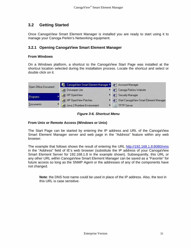
3.2 Getting Started Once CanogaView Smart Element Manager is installed you are ready to start using it to manage your Canoga Perkin’s Networking equipment. 3.2.1 Opening CanogaView Smart Element Manager From Windows On a Windows platform, a shortcut to the CanogaView Start Page was installed at the shortcut location selected during the installation process. Locate the shortcut and select or double click on it.
Figure 3-6. Shortcut Menu From Unix or Remote Access (Windows or Unix) The Start Page can be started by entering the IP address and URL of the CanogaView Smart Element Manager server and web page in the “Address” feature within any web browser. The example that follows shows the result of entering the URL http://192.168.1.8:8080/nms in the “Address” field of IE’s web browser (substitute the IP address of your CanogaView Smart Element Server for 192.168.1.8 in the example shown). Subsequently, this URL or any other URL within CanogaView Smart Element Manager can be saved as a “Favorite” for future access so long as the SNMP Agent or the addresses of any of the components have not changed.
Note: the DNS host name could be used in place of the IP address. Also, the text in this URL is case sensitive.
Enterprise Version 32

CanogaView® Smart Element Manager
Figure 3-7. IE Address Field Example From HP OpenView If you installed CanogaView on a computer running HP OpenView’s NNM and you indicated that it should be integrated with NNM, you can access it from the NNM web interface. Launch the NNM web interface on a Windows platform via URL:
http://canogaview_server_host/OvCgi/ovlaunch.exe Launch the NNM web interface on a UNIX platform via URL:
http://canogaview_server_host:8880/OvCgi/ovlaunch.exe To launch CanogaView from the HP OpenView Launcher window, open the "IT Resources and Applications" item on the Object Views tab. Double-click on "CanogaView". 3.2.2 Start CanogaView Smart Element Manager The CanogaView Start Page provides a starting point from which to access CanogaView. To launch CanogaView from the Start Page, click on the “Start” button.
Enterprise Version 33

CanogaView® Smart Element Manager
Figure 3-8. CanogaView Start Page Additional examples showing access from a client web browser whether local or remote by opening the following URL’s within a web browser:
• Agent Chooser: http://canogaview_server_host:8080/nms/jsp/AgentConfig.jsp
• Directly to the Domain view for the IP address specified: http://canogaview_server_host:8080/nms/jsp/DomainView.jsp?IP_CONTEXT=IP_address_of_the_DMM
• Directly to a particular Chassis View: http://canogaview_server_host:8080/nms/jsp/ChassisView.jsp?IP_CONTEXT=IP_address_of_the_DMM&CHASSIS_CONTEXT=chassis_number
• Account Manager: http://canogaview_server_host:8080/nms/jsp/UsersConfig.jsp
• Security Manager: http://canogaview_server_host:8080/nms/jsp/AppsConfig.jsp
Enterprise Version 34

CanogaView® Smart Element Manager
Next, the CanogaView Smart Element Manager Login screen opens and the user will be prompted to enter a username and a password.
Figure 3-9. Login Screen 3.2.3 Login The standard login screen, shown above, will appear the first time access to any CanogaView Smart Element Manager application (e.g. Agent Chooser, Domain View, 9135 View, Alarm Monitor, etc.) is attempted. After a successful login, any application may then be accessed without having to enter a username and password. The login session continues until the user explicitly logs out or the session times out due to inactivity. If the password for CanogaView has not been established, enter "guest" or "admin" as the username and password. This entry is case sensitive. After a successful login, the Agent Chooser screen will open. The Account Manager Utility application is used for username and password management. See section 3.3.1 for more information on how to use the Account Manager application. 3.2.4 Agent Chooser The CanogaView Smart Element Manager’s SNMP Agent Chooser application (see Figure 3-10) must be used to add each managed SNMP Agent to its database. CanogaView Smart Element Manager must know the IP Address and Agent Type of the SNMP Agent so that the correct management applications are used to access and retrieve data from the managed device using the SNMP protocol and device specific MIB variables. Additionally, it is essential that the IP address of the server on which the CanogaView Smart Element Manager Enterprise software is installed must be added to the SNMP Agent’s host table for each device that is to be managed. Additionally, if trap/alarm monitoring is desired, then the appropriate “access level” and “trap port” must be setup. See Figures: 1-1 and 1-2 in this manual for examples of the DMM and 9135’s telnet user interface. The SNMP Agents currently supported are:
Enterprise Version 35

CanogaView® Smart Element Manager
• Domain Management Module (DMM) for management support of the Universal Chassis System (up to eight 2U and 5U chassis per DMM) and its components.
• 9135 Two Port EdgeAccess™ Switch • 9140 Four Port EdgeAccess™ Switch • 9135G Gigabit Two-port EdgeAccess™ Switch
Click on the "Add Agent" button and an Add Agent window will open. Enter the “IP Address” of the SNMP Agent to be managed and the “Agent Type”. Repeat adding SNMP Agents for each device that you need to manage. To delete an agent, select the agent to delete from the list, click on the “Delete Agent” button, and save the change. Additions, changes and/or deletions to the Agent database must be saved.
Figure 3-10: SNMP Agent Chooser
Enterprise Version 36

CanogaView® Smart Element Manager
Figure 3-11. Add/Edit Agent Screen
Field Name Usage IP Address IP address of the SNMP Agent to be managed. A valid IP address of
the form xxx.xxx.xxx.xxx must be entered.
Description This is a read only field which is returned from the actual unit. Mib variable sysdesc
Agent Type The correct Agent Type must be selected for the IP Address entered. If the value Unknown is set, then the applet will determine the correct Agent Type and set this field accordingly.
Status Polling This fields controls whether the Agent Chooser application should periodically poll the SNMP Agent to determine its status. Default = “enable”.
Name A name assigned by the administrator for the SNMP Agent when created using the Agent Chooser Add feature. This name will appear in the Name column of the Agent Chooser’s list of managed SNMP Agents. Default = “”. Example: CPE-Store xxx.
Location The location of the SNMP Agent assigned by the administrator. This field will appear in the Location column of the Agent Chooser’s list of managed SNMP Agents. Default = “”. Example: Third Floor Closet
Contact The name of someone to contact regarding issues for the SNMP Agent. This field will appear in the Contact column of the Agent Chooser’s list of managed SNMP Agents. Default = “”. Example: Steve x201
SNMP Retries The number of times that the requesting device (SNMP Manager) should resend messages to the SNMP Agent in the event that a timeout has occurred. Default = “3”.
SNMP Timeout Time in milliseconds that a SNMP Agent should respond to a SNMP Get or Set message before a retry is attempted. Default is “50”. Note: 100 = 1 second.
SNMP Get Community The get community name string used in SNMP Get messages. The string entered must match and be identical in case to that within the SNMP Agent in order for get operations to work. Default is “public”.
SNMP Set Community The set community name string used in SNMP Set messages. The string entered must match and be identical in case to that within the SNMP Agent in order for set operations to work. Default is “public”.
Enterprise Version 37

CanogaView® Smart Element Manager
The “Status” column (example below) reports the status of each SNMP Agent being monitored. The Status values of Alive, No Response and Unknown are determined by continuously polling (5 - 120 seconds, default 20) the installed agents using simple SNMP Get requests. This feature helps to determine the proper setup of the user's IP Network by testing if an SNMP packet is able to reach as well as be returned from a SNMP Agent. Status values should be interpreted as follows:
Alive - SNMP Agent is online and responding correctly to SNMP queries.
No Response - SNMP Agent is offline most likely to one of the following reasons: Unit is powered off, incorrect IP address, network latency or timeouts, IP Network router/fire wall problems, incorrect community name, IP address of CanogaView server not entered into DMM's Host table.
Unknown - the application has not yet attempted to query the device. This should only be a temporary condition.
Figure 3-12. Agent Chooser Status Example
3.2.5 Views Views are a graphical representation of the physical device from which other applications can be launched. Views also show the status of the unit by displaying device LEDs and other icons to represent status.
Enterprise Version 38
CanogaView® Smart Element Manager
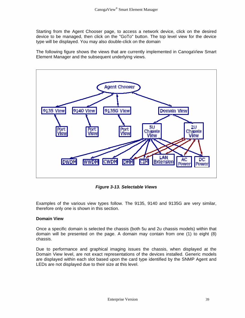
Starting from the Agent Chooser page, to access a network device, click on the desired device to be managed, then click on the "GoTo" button. The top level view for the device type will be displayed. You may also double-click on the domain The following figure shows the views that are currently implemented in CanogaView Smart Element Manager and the subsequent underlying views.
Figure 3-13. Selectable Views Examples of the various view types follow. The 9135, 9140 and 9135G are very similar, therefore only one is shown in this section. Domain View Once a specific domain is selected the chassis (both 5u and 2u chassis models) within that domain will be presented on the page. A domain may contain from one (1) to eight (8) chassis. Due to performance and graphical imaging issues the chassis, when displayed at the Domain View level, are not exact representations of the devices installed. Generic models are displayed within each slot based upon the card type identified by the SNMP Agent and LEDs are not displayed due to their size at this level.
Enterprise Version 39
CanogaView® Smart Element Manager
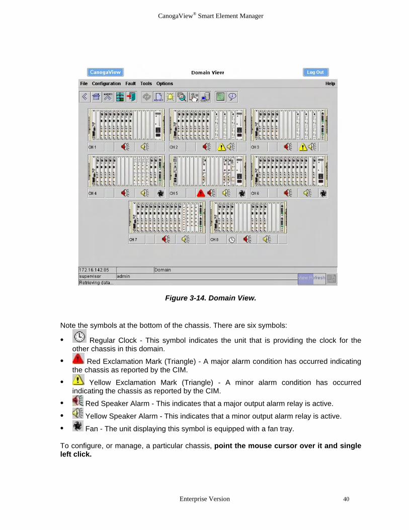
Figure 3-14. Domain View. Note the symbols at the bottom of the chassis. There are six symbols:
• Regular Clock - This symbol indicates the unit that is providing the clock for the other chassis in this domain.
• Red Exclamation Mark (Triangle) - A major alarm condition has occurred indicating the chassis as reported by the CIM.
• Yellow Exclamation Mark (Triangle) - A minor alarm condition has occurred indicating the chassis as reported by the CIM.
• Red Speaker Alarm - This indicates that a major output alarm relay is active.
• Yellow Speaker Alarm - This indicates that a minor output alarm relay is active.
• Fan - The unit displaying this symbol is equipped with a fan tray. To configure, or manage, a particular chassis, point the mouse cursor over it and single left click.
Enterprise Version 40
CanogaView® Smart Element Manager
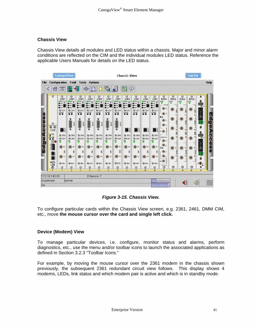
Chassis View Chassis View details all modules and LED status within a chassis. Major and minor alarm conditions are reflected on the CIM and the individual modules LED status. Reference the applicable Users Manuals for details on the LED status.
Figure 3-15. Chassis View.
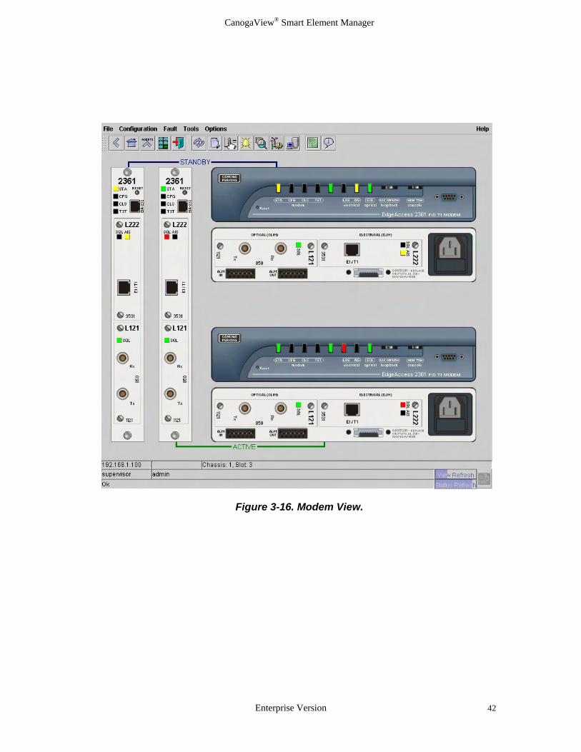
To configure particular cards within the Chassis View screen, e.g. 2361, 2461, DMM CIM, etc., move the mouse cursor over the card and single left click. Device (Modem) View To manage particular devices, i.e. configure, monitor status and alarms, perform diagnostics, etc., use the menu and/or toolbar icons to launch the associated applications as defined in Section 3.2.3 "Toolbar Icons." For example, by moving the mouse cursor over the 2361 modem in the chassis shown previously, the subsequent 2361 redundant circuit view follows. This display shows 4 modems, LEDs, link status and which modem pair is active and which is in standby mode.
Enterprise Version 41
CanogaView® Smart Element Manager
Figure 3-16. Modem View.
Enterprise Version 42

CanogaView® Smart Element Manager
Device (9135G) View Once a 9135G, 9135 or 9140 is selected from the Agent Chooser application, the device and its ports are displayed as well the LED status at both the system and port levels. Reference the applicable Users Manuals for details on the LED status.
Figure 3-17. 9135G View Move the mouse cursor over a port and single left click. The following port view will be displayed.
Figure 3-18. 9135G Port View At either view level, use the menu and/or toolbar icons to launch the associated applications as defined in Section 3.2.3 "Toolbar Icons" at either the switch or port level views.
Enterprise Version 43

CanogaView® Smart Element Manager
3.3 Other Applications 3.3.1 Account Manager To manage login accounts (e.g., add/delete users, set up passwords, etc.) open the Account Manager utility. On a Windows platform, this page can be accessed from the Account Manager shortcut installed during CanogaView installation (see Figure 3-6. Shortcut Menu) or the Utilities option from the CanogaView Start page (see Figure 3-8: CanogaView Start Page). On a UNIX platform or remote windows platform, open the URL for the Account Manager as documented in Section 3.2.1 and 3.2.2.
http://canogaview_server_host:8080/nms/jsp/UsersConfig.jsp Two user login accounts are automatically created when CanogaView is installed: • guest - this is used for both user name and password. This login account has been pre-
installed with the observer access level. • admin - this is used for both user name and password. This login account has been pre-
installed with the Supervisor access level. Note: Taking into consideration security issues, it is advisable to either remove or change the pre-installed access accounts. Use the admin account when establishing new users. To establish new users click the "Add User" button. Fill in the desired user name and password, then select a user security level via the drop-down menu. This setting defines the level of access the user will have upon login. This setting is important and will limit the security level placed upon users for specific applications and fields. Note: Accounts and passwords are case sensitive. After 3 unsuccessful attempts an account will be set to an Enabled State of “locked out” as it will no longer be a valid account until the Enabled State is reset to “enabled” by a user with administrative privileges.
Enterprise Version 44

CanogaView® Smart Element Manager
Figure 3-19: Account Manager
Figure 3-20: Add User
Enterprise Version 45

CanogaView® Smart Element Manager
3.3.2 Alarm Monitor Each graphical views have a button with a yellow bell; the Alarm Monitor. The Alarm Monitor registers to receive events that originate from the chassis, device, etc. When initiated, the Alarm Monitor screen will open with a history of the latest alarms. This monitor operates in real time, thus as one alarm is generated it is reflected in the alarms list while the last alarm in the history file is removed when the maximum number of alarms is received. An alarm database stores Historical Alarm Events for monitoring and reporting purposes. By default, the system is installed with a utility which runs every night at midnight which purges all alarms older than 30 days to a txt file. The purpose of this utility is to prevent the database from becoming too big as the performance of the reporting applications will be impacted significantly. To modify the execution of this utility, find the "service.conf" file within the directory hierarchy where you installed CanogaView Smart Element Manager, and using a standard text editor modify the line which starts with "EventEngine". You will see two variables toward the end of the line (see below) that you can modify to turn this feature "-exportalarms on" or "-exportalarms off", the number of days of which events are considered old "-exportage 30" and the output location where the exported events should be placed "-exportdir xxxx": EventEngine ................... -exportalarms on -exportage 30 -exportdir xxx xxx is the name of the directory where exported event files will be placed. Note that the txt format of these files created allow them to be imported into other desktop applications. Also, each time the purge utility is run a new file with a new date/time stamp as its filename is created which allows one to merge and search through months or years of alarm information.
The Alarm Monitor displays Active alarms and Historical alarms. The Active list will show only those received events that have not yet been cleared (thereby showing the current state of the device(s) monitored). The historical list will show all events that have been received and subsequently cleared. Both lists can be resized.
Alarm Event Correlation services are present such that Link Up events clear Link Down events, Cold Starts clear all events against a device, Card Inserted events clear Card Removed events, Active Optical Link Sync OK clear Active Optical Link Sync Bad events, etc..
Alarm Filtering exists such that whenever a user selects the Alarm Monitor option; all Alarms displayed and subsequently monitored will be that at the device level selected as well as all of its components or underlying views. Thus the Alarm Monitor is opened at the Agent Chooser level then all alarm events for all SNMP agents will be displayed. Subsequently, if the user selects the application while at the Device level, then all alarm events for this device as well as any of it remote managed units will be displayed and monitored.
Enterprise Version 46

CanogaView® Smart Element Manager
An example of alarms when selected at the Agent Chooser level is displayed below. Note that alarms against all of the SNMP Agents in the Agent Chooser’s list will be displayed.
Figure 3-21. Alarm Monitor – All Alarms Filter
Enterprise Version 47

CanogaView® Smart Element Manager
Next, an example of selecting the alarm button at a device level follows:
Figure 3-22. Alarm Monitor – Filtered Example
Other Alarm Monitoring features include:
Select All - a short cut for selecting all of the active alarm events.
Telnet - select an alarm event and launch a telnet session using the IP address of the SNMP Agent.
Goto - select an alarm and go right to the source of the problem, by launching an Graphical View of the device from which all CanogaView applications can be accessed.
Clear Active - allows a user to manually clear an active alarm.
Enterprise Version 48
CanogaView® Smart Element Manager
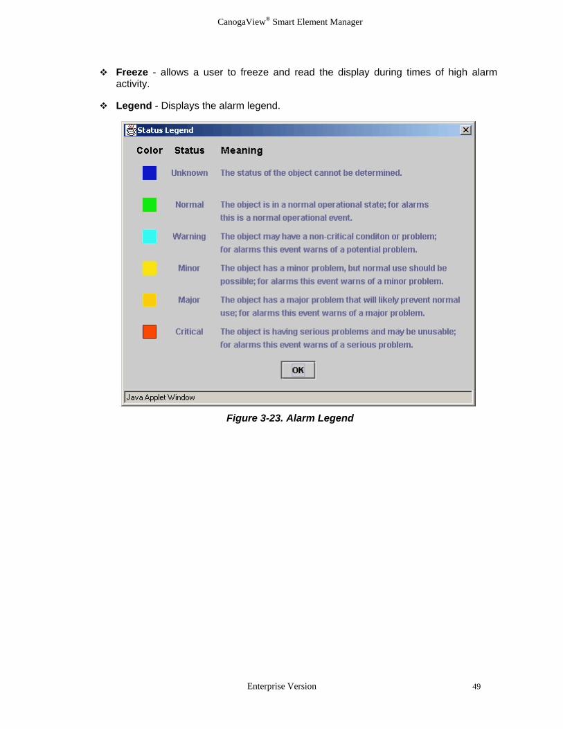
Freeze - allows a user to freeze and read the display during times of high alarm activity.
Legend - Displays the alarm legend.
Figure 3-23. Alarm Legend
Enterprise Version 49

CanogaView® Smart Element Manager
Alarm Event Queries or Reports - generate HTML reports against the alarm data base by Log Time, Source or Severity. These reports can be viewed, searched or printed.
Figure 3-24. Alarm Event Queries
Figure 3-25. Alarms Records by Log Time Input
Enterprise Version 50

CanogaView® Smart Element Manager
Figure 3-26. Example Alarm Report
3.3.3 Configuration
CanogaView Smart Element Manager supports the user in the setup and maintenance of the network by providing a set of Configuration Management features. Through the use of specialized configuration applications which retrieve configuration data directly from the device using SNMP, applications that allow the user to verify and edit parameters, reset devices, download new code, generate reports or telnet to a device are provided.
• Configuration display and edit
• Craft Interface to Device using Telnet (see section 3.3.8)
• Inventory Reports (see section 3.3.5)
• TFTP based Code Download (see section 3.3.9)
• Reset (see section 3.3.4) An example of a 9135G Port Level Configuration application follows:
Enterprise Version 51

CanogaView® Smart Element Manager
Figure 3-27. 9135G Port Configuration
3.3.4 Reset At various levels the user is able to issue reset commands to a device and its components. See the application chart in section 3.1.1 for details. An example of a Fiber Optic Modem Reset application is displayed next. Note that the user can Reset, Reset and Swap, restore the unit to Factory Defaults at a device or circuit level. In all cases, a confirmation message is displayed prior to command execution. Also, the reset of device may cause the unit to go off line or switch to a redundant circuit.
Enterprise Version 52

CanogaView® Smart Element Manager
Figure 3-28. Fiber Optic Modem Reset Example
Figure 3-29. 9135G Reset Example
Enterprise Version 53
CanogaView® Smart Element Manager
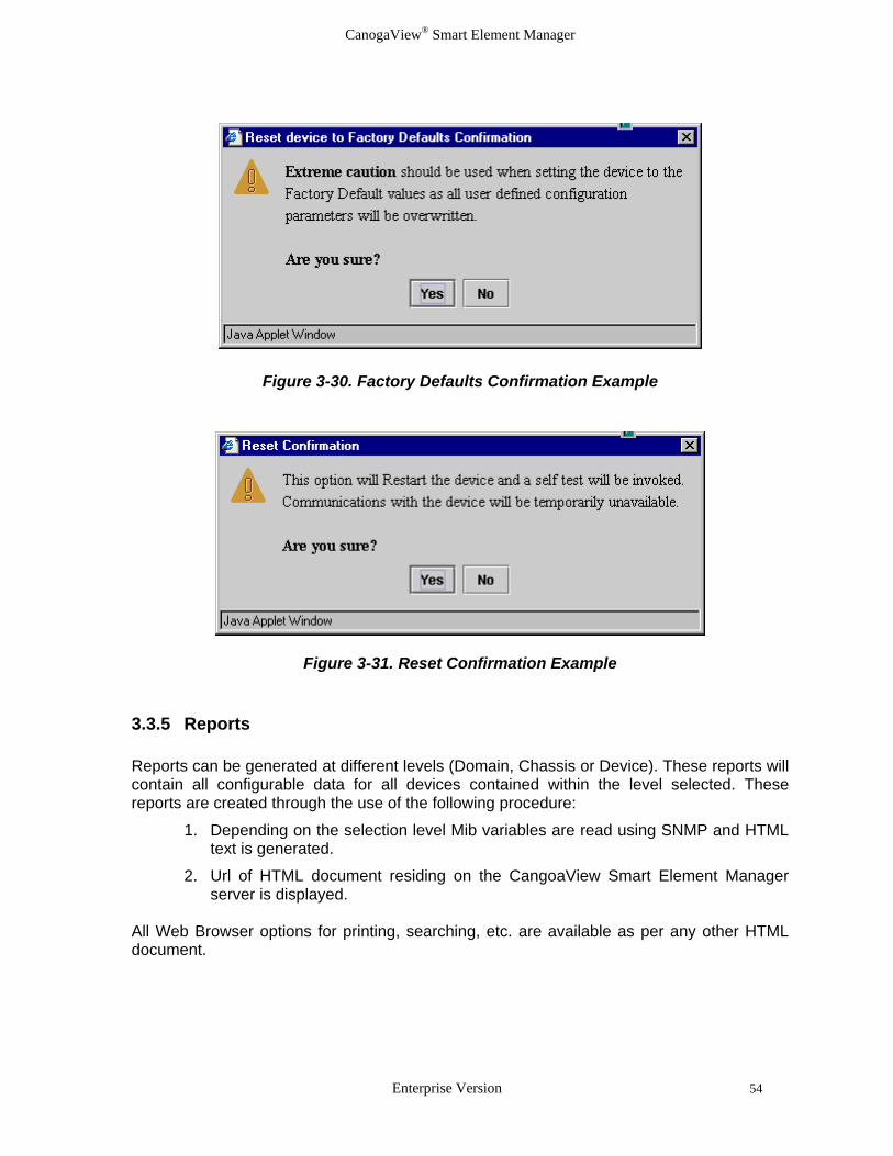
Figure 3-30. Factory Defaults Confirmation Example
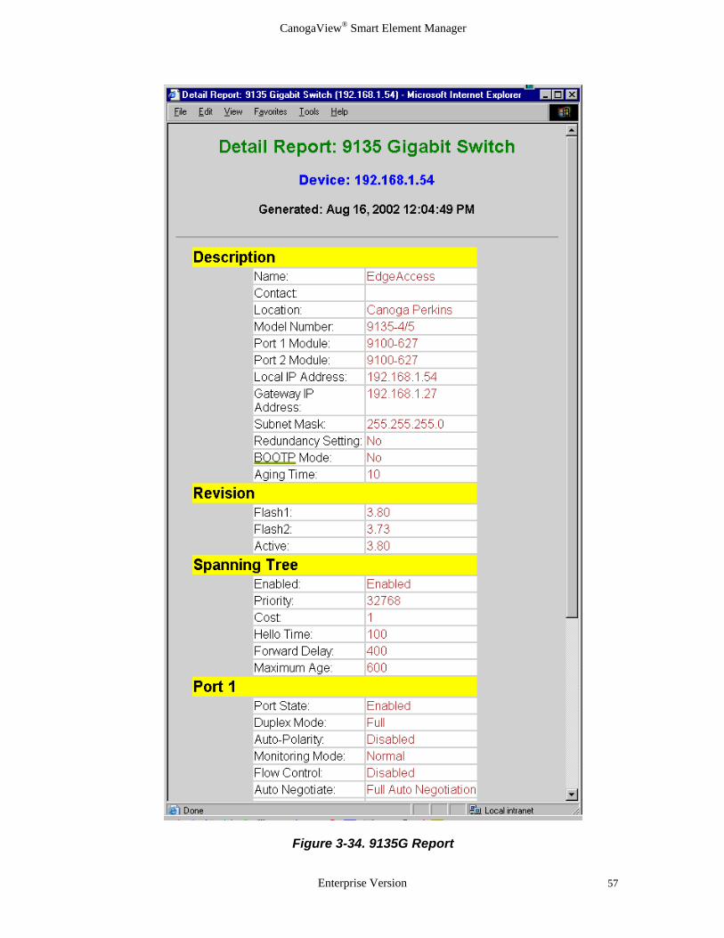
Figure 3-31. Reset Confirmation Example 3.3.5 Reports Reports can be generated at different levels (Domain, Chassis or Device). These reports will contain all configurable data for all devices contained within the level selected. These reports are created through the use of the following procedure:
1. Depending on the selection level Mib variables are read using SNMP and HTML text is generated.
2. Url of HTML document residing on the CangoaView Smart Element Manager server is displayed.
All Web Browser options for printing, searching, etc. are available as per any other HTML document.
Enterprise Version 54

CanogaView® Smart Element Manager
Figure 3-32. Domain Level Reports
Enterprise Version 55

CanogaView® Smart Element Manager
Figure 3-33. Domain Level Report Example
Enterprise Version 56
CanogaView® Smart Element Manager
Figure 3-34. 9135G Report
Enterprise Version 57

CanogaView® Smart Element Manager
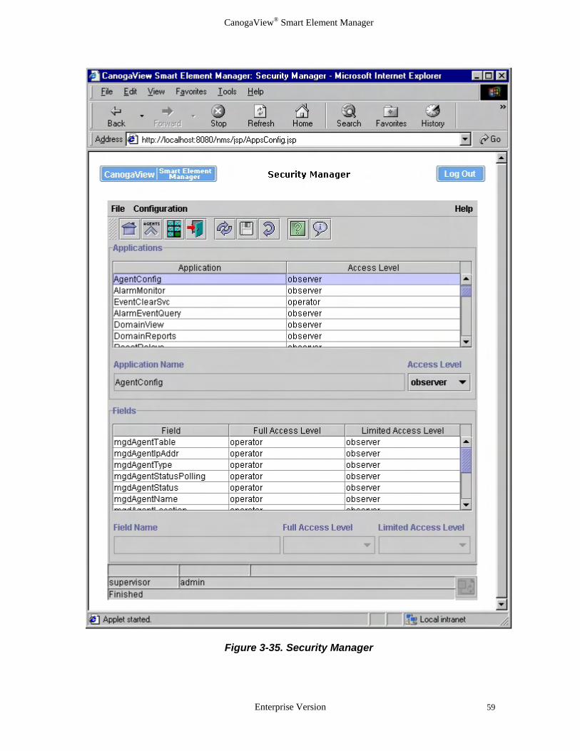
3.3.6 Security Manager Collectively the security features within CanogaView Login, Application Level Security - (Administrator, Operator, Observer), SNMP Community Names, DMM (SNMP Proxy) Trusted Hosts and Server OS Login/Password support provide for a robust secured product. To manage application security, open the Security Manager. On a Windows platform, this page can be accessed from the Security Manager shortcut installed during the CanogaView installation (see Figure 3-6. Shortcut Menu) or the Utilities option from the CanogaView Start page (see Figure 3-8: CanogaView Start Page). On a UNIX platform or remote windows platform, open the URL for the Security Manager as documented in Section 3.2.1 and 3.2.2.
http://canogaview_server_host:8080/nms/jsp/AppsConfig.jsp Each application can have a minimum access level assigned which is required to open the application (e.g., if UsersConfig application is assigned a Supervisor level access, users without this security level will be denied access when attempting to configure the Users data.) Individual fields within the application can also be assigned access levels; "full access," "limited access" and "none." • Full Access - allows read/write privileges for users with the minimum access level (i.e.,
observer, operator, supervisor)
• Limited Access - allows read only privileges for users with the minimum access level (i.e., observer, operator, supervisor)
• None - does not allow the field to be displayed or interacted with any user.
Enterprise Version 58
CanogaView® Smart Element Manager
Figure 3-35. Security Manager
Enterprise Version 59

CanogaView® Smart Element Manager
3.3.7 Status Although the status of a device is implied at many levels through the use of color, alarms, graphical displays, etc., device specific status applications will display mib fields that show all relevant information about a device. Additional information such as version information will also be displayed so that the user does not have to bounce around between status and configurations applications in order to gather the information that is generally required in order to diagnose a problem. The information displayed will closely match that which is displayed via the telnet interface. Polling the status related snmp mib variables for a device is the method used to update the contents of the status applications. Options are provided to allow the user to control the polling intervals. The default will be 10 seconds, and the range will be from 5 to 120 seconds. Status examples follow:
Figure 3-36. Chassis Status
Enterprise Version 60

CanogaView® Smart Element Manager
The following status example(s) show each tab that may be displayed when the status application is invoked at the 9135G device level.
Figure 3-37. 9135G Status – General Tab
Enterprise Version 61

CanogaView® Smart Element Manager
Figure 3-38. 9135G Status – Spanning Tree Tab
Enterprise Version 62

CanogaView® Smart Element Manager
Figure 3-39. 9135G Status – Forwarding Database Tab
Figure 3-40. 9135G Status – Version Tab
Enterprise Version 63
CanogaView® Smart Element Manager
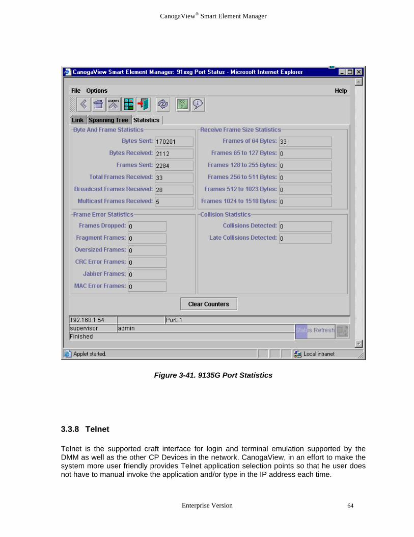
Figure 3-41. 9135G Port Statistics 3.3.8 Telnet Telnet is the supported craft interface for login and terminal emulation supported by the DMM as well as the other CP Devices in the network. CanogaView, in an effort to make the system more user friendly provides Telnet application selection points so that he user does not have to manual invoke the application and/or type in the IP address each time.
Enterprise Version 64

CanogaView® Smart Element Manager
Figure 3-42. DMM Telnet Example 3.3.9 TFTP Server The TFTP Server Utility monitors the TFTP file transfer activities on the CanogaView Smart Element Manager Server. TFTP "Trivial File Transfer Protocol" is used to transfer files (firmware) from the CanogaView Smart Element Manager Server to the SNMP Agent (DMM) for subsequent downloading to one or more targeted Canoga Perkins's products. The SNMP Agent requests the files from the TFTP Server process; therefore once the TFTP Server is started it sits idle waiting for file transfer requests.
The TFTP Server process can only be started from and executed on the CanogaView Smart Element Manager Web Server. You may manually start the TFTP Server Utility so that it only runs when needed during firmware upgrades or automate the startup runs whenever the CanogaView Smart Element Manager Server is running by using the shortcut installed during CanogaView installation (see Figure 3-6. Shortcut Menu) or the Utilities option from the CanogaView Start page (see Figure 3-8: CanogaView Start Page).
To automate the startup of the TFTP Server, add the "TFTP Server" shortcut within the "CanogaView Smart Element Manager" programs folder to the "Startup" group.
TFTP Server help is available online.
Enterprise Version 65

CanogaView® Smart Element Manager
Enterprise Version 66
Figure 3-43. TFTP Server Utility
Figure 3-44. TFTP Help

CanogaView® Smart Element Manager
Chapter 4 Frequently Asked Questions The following list of frequently asked questions is installed on the CanogaView Smart Element Manager Server under the Technical Support option. 4.1 What Web Server Platforms are supported?
The Enterprise Version of CanogaView Smart Element Manager supports the following server platforms:
• HP workstation running HP-UX version 11.0
• Sun workstation running Sun Solaris OS version 7 (a.k.a. Solaris 2.7, SunOS 5.7)
• PC workstation running Windows NT 4.0 SP4, Windows 2000 or XP.
4.2 What Web Client Platforms are supported?
Client access to the Enterprise Version can be performed on any of the following platforms:
• HP-UX - Netscape Navigator 4.75 with Java Plug-In 1.3.0_01
• Windows NT, 98 or 2000 - Netscape Navigator 4.06 -or- Microsoft Internet Explorer 4.0, both with Java Plug-In 1.3.0_01
• Sun Solaris - Netscape Navigator 4.76 with Java Plug-In 1.3.0_01
• Linux - with Java Plug-In 1.3.0_01
4.3 What Web Server is used by CanogaView Smart Element Manager?
Tomcat 3.2. Refer to http://jakarta.apache.org/tomcat for more information. 4.4 What is a Java Plug-In or Java Runtime Environment? Java Plug-in software enables customers to run Java applets or on their web browser using Sun's Java 2 Runtime Environment, Standard Edition (JRE) instead of the web browser's default virtual machine. Sun's JRE provides a Java Compatible environment for today's widely adopted web browsers - that means consistency and reliability when running applets.
Refer to http://java.sun.com/products/plugin/ for more information.
4.5 How many Web Clients are supported? By default, the Enterprise Version is installed with a one seat user license. This license restricts the support such that only one active client web session is allowed at a time. 10 seat and unlimited seat upgrade options are available.
Enterprise Version 67

CanogaView® Smart Element Manager
4.6 How many User Accounts are supported? No limitation.
4.7 How do I Install CanogaView Smart Element Manager? Refer to the CanogaView Smart Element Manager manual and the Installation Notes for instructions on how to Install CanogaView Smart Element Manager. The manual is available in hardcopy or at www.canoga.com. The Notes are available in hardcopy, on the installation CD, at http://localhost:8080/nms/html/read_win.txt.or at www.canoga.com.
4.8 How do I Uninstall CanogaView Smart Element Manager? Refer to the Installation Notes for instructions on how to Uninstall CanogaView Smart Element Manager. The Notes are available in hardcopy, on the installation CD, at http://localhost:8080/nms/html/read_win.txt.or at www.canoga.com.
4.9 How do I Login? Two user accounts are installed with the system: "guest" and "admin" with passwords "guest" and "admin" respectively. The "guest" user is assigned "observer" access and the "admin" user is assigned "supervisor" access.
It is suggested that the Administrator change these passwords to prevent unauthorized access.
For security reasons, this version of CanogaView Smart Element Manager will administratively "lock out" any user account after the third consecutive unsuccessful login attempt. The locked out account may be re-enabled via the Account Manager applet. In the case that the Administrator himself has been locked out, contact CanogaView Smart Element Manager Technical Support for a resolution.
4.10 Why doesn't CanogaView Smart Element Manager support Netscape 6.0? Netscape 6 does not support LiveConnect which CanogaView Smart Element Manager uses to communicate between its applets and the web browser pages. This restricts CanogaView Smart Element Manager from opening a new browser window from within its applets, ability to handle the items such as "Close Other Windows" or bringing an existing window to the foreground. Until Netscape 6 supports this feature, which Netscape 4.X supports, CanogaView Smart Element Manager will not be able to support Netscape 6.
This is from the Netscape 6 release notes at http://home.netscape.com/eng/mozilla/ns6/relnotes/6.0.html#new : LiveConnect is not yet enabled in this release. LiveConnect and LiveConnect security will be enabled in a later release.
Enterprise Version 68

CanogaView® Smart Element Manager
Netscape 6.2 with Java Plug-in 1.3.1 or later works correctly.
4.11 What Version of HP OpenView can CanogaView Smart Element Manager be integrated with?
HP OpenView Network Node Manager 6.1. Refer to the platform specific read me files for HP NNM patch information. 4.12 What does CanogaView Smart Element Manager actually do? The CanogaView Smart Element Manager Server is basically responsible for the following major features:
o provides Web Server facilities for the CanogaView Smart Element Manager Web Clients
o storage and management of the CanogaView Smart Element Manager applications and databases
o SNMP support to Canoga Perkins SNMP Agents
o Tftp Download facilities for device upgrade support
As all CanogaView Smart Element Manager applets execute within a Web Browser (either Netscape or Internet Explorer), the browser must be capable of supporting the Java Plug-In.
4.13 Which Canoga Perkin's Products does CanogaView Smart Element Manager manage? Presently support is provided for the UCS 2U and 5U Chassis and all of their respective devices as well as the LAN Extension 9135/40 and 9135 Gigabit products and their components.
4.14 What versions of the products must be installed? Refer to Canoga Perkin's web site for product specific firmware available for the most up-to-date information.
4.15 What is a Domain? In the context of the UCS 2U and 5U chassis; a domain is a set of products installed within a group of chassis (maximum 8) which are managed by a single DMM device (SNMP Agent). Each chassis has 16 slots and chassis are connected via a CIM card and cable. Additionally, remote devices which can be accessed via side-band management can also be managed.
Enterprise Version 69

CanogaView® Smart Element Manager
Enterprise Version 70
4.16 How are Remote Products managed? Remote products are managed via a side-band management channel.
4.17 What Security Levels does CanogaView Smart Element Manager support? The 3 levels of security are Supervisor, Operator and Observer. By default, CanogaView Smart Element Manager is installed using the following premises:
o Users with Supervisor access perform administrative functions such as the setup of user accounts and security customization, along with all features within all applications.
o Users with Operator access can execute all features within all of the applications including the resetting of units, running diagnostics, configuration changes, etc. but they are restricted from using administrative functions.
o User with Observer access can execute all applications like that of an Operator, but their is Read-Only in that they cannot reset units, run diagnostic procedures, clear status counters, etc..

CanogaView® Smart Element Manager
Chapter 5 Troubleshooting The following is a list of typical troubleshooting techniques that can be used to determine and correct a problem. 5.1 No Response from SNMP Agent If the applications are showing the error "No Response from SNMP Agent", verify the following:
1. That the CanogaView Smart Element Manager Web Server's address is entered into the SNMP Agent's (DMM's or 9135/40, etc.) host table. The SNMP agents will only respond to those IP addresses listed in its host table.
2. That the Agent's Default Gateway field is set correctly. A correct Default Gateway is required in a routed environment to ensure that IP connectivity is possible from the SNMP Agent to the CanogaView Smart Element Manager Web Server.
3. That you can Ping the SNMP Agent from the CanogaView Smart Element Manager Web Server and vice versa.
4. That you can Telnet to the SNMP Agent from the CanogaView Smart Element Manager Web Server.
5. From the CanogaView Smart Element Manager Web Server, try running running traceroute to trace the route from the CanogaView Smart Element Manager Web Server to the SNMP Agent. Failures can indicate a problem with a router setup or the Default Gateway setting on the Agent.
6. Verify the correct SNMP Community names are being used within the Agent Chooser and match those in the SNMP Agent's System Configuration parameters.
7. If you have access to a SNMP Mib Browser software, see if you can access the SNMP Agent.
8. If you have access to a protocol analyzer, monitor the connection to see if any SNMP traffic is present for these IP addresses.
9. Try resetting the SNMP Agent.
10. Contact Technical Support.
5.2 "Model Not Found" image appears on my View This image appears when CanogaView Smart Element Manager is unable to find a match between the model number reported by the device to an image file located at the CanogaView Smart Element Manager server. Verify the model number reported by the device by telneting to the device or placing the cursor over the image from which the tooltip will display the model number.
Enterprise Version 71
CanogaView® Smart Element Manager
Contact technical support with this information for a resolution.
5.3 Traps/Alarm Processing If you are experiencing problems receiving alarms in the Alarm Monitor, there are several things you can do to troubleshoot the problem:
1. Make sure that the IP address of the CanogaView Smart Element Manager server computer is listed in the Host Table of the SNMP Agent from which alarms are expected, and that the Access Level for this IP address is "4" (Read/Write/Trap).
Example DMM instructions: To do this, start a Telnet session to the DMM. On the MAIN MENU, select "1" to access the Domain Management Module. On the DOMAIN MANAGEMENT MODULE screen, select "6" to view the Host Table. Add or edit an IP address entry for the CanogaView Smart Element Manager server as needed.
2. Verify that you have IP connectivity from the SNMP Agent to the CanogaView Smart Element Manager server by pinging the server from the device.
Example DMM instructions: Start a Telnet session to the DMM. On the MAIN MENU, select "1" to access the Domain Management Module. On the DOMAIN MANAGEMENT MODULE screen, select "3", Ping Generation. On the PING MENU screen, enter the IP address of the CanogaView Smart Element Manager server computer and a number of ping attempts to make. Hit Enter to start the test. If ping requests are sent but not received, it indicates a lack of IP connectivity from the SNMP Agent to the server. In this case, it is not possible for CanogaView Smart Element Manager to receive SNMP traps from the SNMP Agent. Contact your system or network administrator for help with troubleshooting a network problem.
3. Verify that the CanogaView Smart Element Manager services needed for trap processing are running, and stop/restart them if necessary. Windows NT/2000 Open the Services application (Start->Settings->Control Panel: Services) and look for the "CanogaView Smart Element Manager" service. The status of this service should be "Started"; if it is not, select the "CanogaView Smart Element Manager" list item and click the Start button.
If after troubleshooting alarms are still not being received, you can try to stop and restart the services by selecting the "CanogaView Smart Element Manager" service list item, clicking on "Stop", then "Start".
4. Determine if SNMP traps sent by the SNMP Agent are arriving at the CanogaView Smart
Element Manager server computer by looking at syslog messages. On Windows NT/2000, execute the following program to display syslog messages:
nms-install-directory\syslogd\2.2\syslogd-2.2\application\SyslogD.exe
Enterprise Version 72

CanogaView® Smart Element Manager
For each trap received, you should see messages from "TRAPSERVICE" and "EVENTENGINE".
5. Make sure that the CanogaView Smart Element Manager Trap Service is listening for SNMP traps on the correct port. The Trap Service listens for SNMP traps on the port number specified during the installation; this should be port 163 for computers that have HP's Network Node Manager or other network management packages installed, and port 162 otherwise. If configured incorrectly, Trap Service will either fail to start or will not process any traps. You can verify the configured port number by opening the service.conf file in your CanogaView Smart Element Manager installation directory with a text editor. The number following the string "-trapport" is the port number. If this number is incorrect, change it, save the change, and stop/restart the CanogaView Smart Element Manager services as documented above.
Enterprise Version 73

CanogaView® Smart Element Manager
Enterprise Version 74

CanogaView® Smart Element Manager
Appendix A Warranty Information Current Warranty information is available on-line in the Client Login Area of the Canoga Perkins web site (www.canoga.com) or by contacting Technical Support at 800-360-6642 (voice) or [email protected] (email).
Enterprise Version A-1


CANOGA PERKINS CORPORATION 20600 Prairie Street
Chatsworth, California 91311-6008 USA Phone: (818) 718-6300 FAX: (818) 718-6312
Web Site: www.canoga.com Email: [email protected]