Canadian Human View Handbook - Defence Research...
63
Canadian Human View Handbook Curtis Coates CMC Electronics Andrew Stewart CMC Electronics Wenbi Wang DRDC Toronto Prepared By: Esterline | CMC Electronics 415 Legget Drive, PO Box 13330 Ottawa, ON, CANADA K2K 2B2 Human Factors Engineer Contractor's Document Number: 1000-1505 Contract Project Manager: Randy Meiklejohn, 613-592-7400 x 2278 PWGSC Contract Number: W7719-115018/001/TOR CSA: Wenbi Wang, Defence Scientist, 416-635-2000 x 3063 The scientific or technical validity of this Contract Report is entirely the responsibility of the Contractor and the contents do not necessarily have the approval or endorsement of Defence R&D Canada. Defence R&D Canada – Toronto Contract Report DRDC Toronto CR 2013-041 July 2013
Transcript of Canadian Human View Handbook - Defence Research...
Canadian Human View Handbook
Curtis Coates CMC Electronics Andrew Stewart CMC Electronics Wenbi Wang DRDC Toronto Prepared By: Esterline | CMC Electronics 415 Legget Drive, PO Box 13330 Ottawa, ON, CANADA K2K 2B2 Human Factors Engineer Contractor's Document Number: 1000-1505 Contract Project Manager: Randy Meiklejohn, 613-592-7400 x 2278 PWGSC Contract Number: W7719-115018/001/TOR CSA: Wenbi Wang, Defence Scientist, 416-635-2000 x 3063 The scientific or technical validity of this Contract Report is entirely the responsibility of the Contractor and the contents do not necessarily have the approval or endorsement of Defence R&D Canada.
Defence R&D Canada – Toronto Contract Report DRDC Toronto CR 2013-041 July 2013

Principal Author
Original signed by Curtis Coates
Curtis Coates
Project Lead
Approved by
Original signed by Dr. Wenbi Wang
Dr. Wenbi Wang
Scientific Authority
Approved for release by
Original signed by Dr. Joseph V. Baranski
Dr. Joseph V. Baranski
Chair, Knowledge and Information Management Committee
© Her Majesty the Queen in Right of Canada, as represented by the Minister of National Defence, 2013
© Sa Majesté la Reine (en droit du Canada), telle que représentée par le ministre de la Défense nationale, 2013

DRDC Toronto CR 2013-041 i
Abstract ……..
With the rapid advancement of information technology and acquisition reform within Allied defence communities, enterprise architecture has emerged and become an effective approach to support the management of complex systems and their evolution over time. Architecture frameworks such as the Department of National Defence / Canadian Forces Architecture Framework (DNDAF) specify a common approach for development, presentation, and integration of architectural descriptions. While international architecture frameworks evolve to include new concepts in System Engineering, the portrayal of the human as a unique part of the system has not been well addressed. An architectural viewpoint is required to explicitly represent the human and document the unique implications humans bring into and impose on enterprise system design. To that end, the idea of a Human View (HV), which leverages Human Systems Integration (HSI) principles and practices, has emerged. The purpose of HV is to capture human characteristics, their work requirements, and inform how they interact with technological systems to support enterprise objectives. This document defines a set of HV that was developed to enhance DNDAF, with a particular focus on supporting DND acquisition projects.
Résumé ….....
Compte tenu de la poussée rapide de la technologie de l’information et de la réforme de l’acquisition au sein des collectivités de la défense des Alliés, l’architecture d’entreprise a fait son apparition et est devenue une démarche efficace pour appuyer la gestion de systèmes complexes et leur évolution au fil du temps. Les cadres d’architecture, comme le Cadre d’architecture du ministère de la Défense nationale et des Forces canadiennes (CA MDN), décrivent une démarche commune pour le développement, la présentation et l’intégration des descriptions architecturales. Bien que les cadres architecturaux internationaux évoluent pour inclure de nouveaux concepts en systémique, on n’a pas bien tenu compte de la représentation de l’être humain comme élément unique du système. Il faut un point de vue architectural pour représenter de façon explicite l’être humain et pour documenter les particularités que l’être humain apporte et impose à la conception du système d’entreprise. À cette fin, le concept de perspective humaine (PH), qui tire parti des principes et des pratiques de l’intégration des systèmes humaines (ISH), a fait surface.
La raison d’être de la PH est de saisir les caractéristiques des être humains, leurs exigences professionnelles, ainsi que de guider leur façon d’interagir avec les systèmes technologiques à l’appui des objectifs de l’entreprise. Le présent document définit un ensemble de PH qui a été élaboré afin d’améliorer le CA MDN, en mettant surtout l’accent sur le soutien aux projets d’acquisition du MDN.

ii DRDC Toronto CR 2013-041
This page intentionally left blank.

DRDC Toronto CR 2013-041 iii
Executive summary
Canadian Human View Handbook: Curtis Coates; Andrew Stewart; Wenbi Wang DRDC Toronto CR 2013-041; Defence R&D Canada – Toronto; July 2013.
Introduction or background: With the rapid advancement of information technology and acquisition reform within Allied defence communities, enterprise architecture has emerged and become an effective approach to support the management of complex systems and their evolution over time. Architecture frameworks such as the Department of National Defence / Canadian Forces Architecture Framework (DNDAF) specify a common approach for development, presentation, and integration of architectural descriptions. Architectural models based on DNDAF depict multiple, complementary aspects of a complex enterprise system. These models can be either used alone or integrated together to support stakeholder decision-making from various perspectives. While international architecture frameworks evolve to include new concepts in System Engineering, the portrayal of the human as a unique part of the system has not been well addressed. An architectural viewpoint is required to explicitly represent the human dimension and document the unique implications humans bring into and impose on enterprise system design. To that end, the idea of a Human View (HV), which leverages Human Systems Integration (HSI) principles and practices, has emerged. The purpose of HV is to capture human characteristics, their work requirements, and inform how they interact with technological systems to support enterprise objectives.
Results: Based on the Department of National Defence (DND)’s requirements, the following set of ten sub-views was developed in this project, collectively regarded as the Canadian HV:
HV-1 (Concept) provides a high level pictorial depiction of the human component in the enterprise.
HV-2 (Establishment) provides a complete list of enterprise personnel based on the needs of the architecture project.
HV-3 (Organization) is a chart diagram that depicts the organization of all individuals that are specified in the corresponding HV-2 model.
HV-4 (Manpower projection) provides a forecast of manpower requirement for the modelled enterprise over a time line that is defined according to the purpose of architecture project.
HV-5 (Personal characteristics) describes the personal characteristics for each individual, including physical, sensory, psychological, sociological attributes,
HV-6 (Training needs) is a tabular summary of training and education gaps between an individual’s qualification, skills, experience and those required by his/her jobs.

iv DRDC Toronto CR 2013-041
HV-7 (System safety) summaries safety related management and engineering tasks that are required to identify prominent and foreseeable risks that may lead to potential accidents or mishaps and threaten the function of the enterprise.
HV-8 (Health hazards) provides a summary of prominent and foreseeable factors that may cause reduced job performance, illness, injury, and disability for enterprise personnel.
HV-9 (Human tasks) is a tabular description of the operator tasks that each individual needs to perform.
HV-10 (Communications) is a graphical and/or tabular description of communication requirements for supporting team functions and performance.
This handbook explains each sub-view in detail and suggests development instructions that may be followed in the architecture modelling process.
Significance: HV enables a better representation of the human element in enterprise architectures and supports stakeholder decision-making by providing a structured linkage from enterprise requirements to manpower, personnel, training, and human factors engineering solutions. It provides a suitable mechanism to embed HSI considerations into the decision making processes in DND capital procurement projects and ensure the single greatest cost driver, people, is addressed 'up front'.
Future plans: The primary focus of future research is the incorporation of HV into DNDAF, which assists the integration of HSI practices into the mainstream system engineering processes and promotes user-centered engineering solutions.
DRDC Toronto CR 2013-041 v
Sommaire .....
Canadian Human View Handbook: Curtis Coates; Andrew Stewart; Wenbi Wang DRDC Toronto CR 2013-041 ; R & D pour la défense Canada – Toronto; juillet 2013.
Introduction or background: With the rapid advancement of information technology and acquisition reform within Allied defence communities, enterprise architecture has emerged and become an effective approach to support the management of complex systems and their evolution over time. Architecture frameworks such as the Department of National Defence / Canadian Forces Architecture Framework (DNDAF) specify a common approach for development, presentation, and integration of architectural descriptions. Architectural models based on DNDAF depict multiple, complementary aspects of a complex enterprise system. These models can be either used alone or integrated together to support stakeholder decision-making from various perspectives. While international architecture frameworks evolve to include new concepts in System Engineering, the portrayal of the human as a unique part of the system has not been well addressed. An architectural viewpoint is required to explicitly represent the human dimension and document the unique implications humans bring into and impose on enterprise system design. To that end, the idea of a Human View (HV), which leverages Human Systems Integration (HSI) principles and practices, has emerged. The purpose of HV is to capture human characteristics, their work requirements, and inform how they interact with technological systems to support enterprise objectives.
Results: Based on the Department of National Defence (DND)’s requirements, the following set of ten sub-views was developed in this project, collectively regarded as the Canadian HV:
HV-1 (Concept) provides a high level pictorial depiction of the human component in the enterprise.
HV-2 (Establishment) provides a complete list of enterprise personnel based on the needs of the architecture project.
HV-3 (Organization) is a chart diagram that depicts the organization of all individuals that are specified in the corresponding HV-2 model.
HV-4 (Manpower projection) provides a forecast of manpower requirement for the modelled enterprise over a time line that is defined according to the purpose of architecture project.
HV-5 (Personal characteristics) describes the personal characteristics for each individual, including physical, sensory, psychological, sociological attributes,
HV-6 (Training needs) is a tabular summary of training and education gaps between an individual’s qualification, skills, experience and those required by his/her jobs.

vi DRDC Toronto CR 2013-041
HV-7 (System safety) summaries safety related management and engineering tasks that are required to identify prominent and foreseeable risks that may lead to potential accidents or mishaps and threaten the function of the enterprise.
HV-8 (Health hazards) provides a summary of prominent and foreseeable factors that may cause reduced job performance, illness, injury, and disability for enterprise personnel.
HV-9 (Human tasks) is a tabular description of the operator tasks that each individual needs to perform.
HV-10 (Communications) is a graphical and/or tabular description of communication requirements for supporting team functions and performance.
This handbook explains each sub-view in detail and suggests development instructions that may be followed in the architecture modelling process.
Significance: HV enables a better representation of the human element in enterprise architectures and supports stakeholder decision-making by providing a structured linkage from enterprise requirements to manpower, personnel, training, and human factors engineering solutions. It provides a suitable mechanism to embed HSI considerations into the decision making processes in DND capital procurement projects and ensure the single greatest cost driver, people, is addressed 'up front'.
Future plans: The primary focus of future research is the incorporation of HV into DNDAF, which assists the integration of HSI practices into the mainstream system engineering processes and promotes user-centered engineering solutions.
DRDC Toronto CR 2013-041 vii
Table of contents
Abstract …….. ................................................................................................................................. iRésumé …..... ................................................................................................................................... iExecutive summary ........................................................................................................................ iiiSommaire ..... ................................................................................................................................... vTable of contents ........................................................................................................................... viiList of Figures ................................................................................................................................ ixList of tables .................................................................................................................................... x1 Background ............................................................................................................................... 1
1.1 Enterprise architectural framework ............................................................................... 21.2 DND/CF Architecture Framework (DNDAF) ............................................................... 21.3 Human View (HV) ........................................................................................................ 31.4 NATO HV framework ................................................................................................... 31.5 Approach to Tailoring the NATO HV ........................................................................... 31.6 Alignment between Canadian HV and HSI framework ................................................ 4
2 The Canadian Human View ..................................................................................................... 72.1 HV-1 Concept ................................................................................................................ 7
2.1.1 Purpose ................................................................................................................ 72.1.2 Prerequisite .......................................................................................................... 82.1.3 Instruction ............................................................................................................ 82.1.4 Representation ..................................................................................................... 8
2.2 HV-2 Establishment .................................................................................................... 112.2.1 Purpose .............................................................................................................. 112.2.2 Prerequisite ........................................................................................................ 122.2.3 Instruction .......................................................................................................... 122.2.4 Representation ................................................................................................... 13
2.3 HV-3 Organization ...................................................................................................... 142.3.1 Purpose .............................................................................................................. 152.3.2 Prerequisite ........................................................................................................ 152.3.3 Instruction .......................................................................................................... 152.3.4 Representation ................................................................................................... 16
2.4 HV-4 Manpower projection ........................................................................................ 182.4.1 Purpose .............................................................................................................. 182.4.2 Prerequisite ........................................................................................................ 192.4.3 Instruction .......................................................................................................... 192.4.4 Representation ................................................................................................... 19
2.5 HV-5 Personal characteristics ..................................................................................... 202.5.1 Purpose .............................................................................................................. 21

viii DRDC Toronto CR 2013-041
2.5.2 Prerequisite ........................................................................................................ 212.5.3 Instruction .......................................................................................................... 212.5.4 Representation ................................................................................................... 22
2.6 HV-6 Training needs ................................................................................................... 242.6.1 Purpose .............................................................................................................. 242.6.2 Prerequisite ........................................................................................................ 242.6.3 Instruction .......................................................................................................... 252.6.4 Representation ................................................................................................... 25
2.7 HV-7 System safety ..................................................................................................... 272.7.1 Purpose .............................................................................................................. 272.7.2 Prerequisite ........................................................................................................ 272.7.3 Instruction .......................................................................................................... 272.7.4 Representation ................................................................................................... 28
2.8 HV-8 Health hazards ................................................................................................... 292.8.1 Purpose .............................................................................................................. 292.8.2 Prerequisite ........................................................................................................ 292.8.3 Instruction .......................................................................................................... 292.8.4 Representation ................................................................................................... 31
2.9 HV-9 Human tasks ...................................................................................................... 322.9.1 Purpose .............................................................................................................. 322.9.2 Prerequisite ........................................................................................................ 322.9.3 Instruction .......................................................................................................... 332.9.4 Representation ................................................................................................... 33
2.10 HV-10 Communications .............................................................................................. 342.10.1 Purpose .............................................................................................................. 352.10.2 Prerequisite ........................................................................................................ 352.10.3 Instruction .......................................................................................................... 352.10.4 Representation ................................................................................................... 36
3 Further discussions ................................................................................................................. 403.1 Fit-For-Purpose Sub-Views ......................................................................................... 403.2 Application of the HV in the Acquisition Process ...................................................... 42
References ….. .............................................................................................................................. 44List of symbols/abbreviations/acronyms/initialisms ..................................................................... 46Distribution list .............................................................................................................................. 48

DRDC Toronto CR 2013-041 ix
List of Figures
Figure 1: Conceptual illustration of Canadian HSI. ........................................................................ 4
Figure 2: An HV-1 (Concept) model for RCN ship crewing analysis. ........................................... 9
Figure 3: A sample HV-1 (Concept) model of the existing RCAF CAOC. .................................. 10
Figure 4: A sample HV-1 (Concept) model of V-CAOC. ............................................................. 10
Figure 5: An OV-1 (High-level operational concept graph) model of CAOC (Adapted from [4]). .............................................................................................................................. 11
Figure 6: Suggested graphical elements for depicting an HV-3 (Organization) model. ............... 15
Figure 7: The HV-3 graphical elements, as manifested in a DND use case study. ....................... 16
Figure 8: A sample HV-3 (Organization) model for CAOC (the reduced as-is model). ............... 17
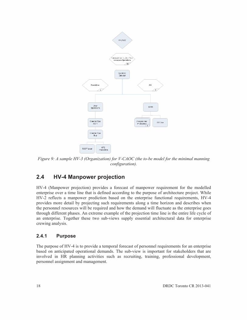
Figure 9: A sample HV-3 (Organization) for V-CAOC (the to-be model for the minimal manning configuration). .............................................................................................. 18
Figure 10: A sample graphical HV-10 (Communications) model for CAOC analysis (i.e., TARM production) ...................................................................................................... 37
Figure 11: Project management phases (note, SS(ID) = Synopsis Sheet (Identification); PPA=Preliminary Project Approval; EPA=Effective Project Approval; FOC=Full Operational Capability; PRC=Project Completion Report). ....................................... 42

x DRDC Toronto CR 2013-041
List of tables
Table 1: Human View Reference Chart. ......................................................................................... 6
Table 2: A sample HV-2 (Establishment) model for V-CAOC (Minimum manning) .................. 13
Table 3: A sample HV-2 (Establishment) model for V-CAOC (Medium manning) .................... 13
Table 4: A sample HV-2 (Establishment) model for V-CAOC (Maximum manning) ................. 14
Table 5: A sample HV-4 (Manpower projection) model for V-CAOC analysis. .......................... 20
Table 6: Sample data elements, including personal characteristics and their assessment criteria, for modeling an HV-5 (Personal characteristics). .......................................... 22
Table 7: A sample HV-5 (Personal Characteristics) model for V-CAOC ..................................... 23
Table 8: A list of data elements for an HV-6 (Training needs) model. ......................................... 25
Table 9: An HV-6 (Training needs) model for V-CAOC analysis. ............................................... 26
Table 10: Suggested data elements for describing System Safety tasks in HV-7 (System safety). ......................................................................................................................... 27
Table 11: A sample HV-7 (System Safety) model template for a generic acquisition project. ..... 28
Table 12 : A description of the basic data elements for HV-8 (Health hazards) ........................... 29
Table 13 : Definition of risk assesssment criteria. ......................................................................... 30
Table 14 : A risk assessment matrix .............................................................................................. 31
Table 15: A sample HV-8 (Health hazards) model. ...................................................................... 32
Table 16: A sample HV-9 (Human tasks) model. ......................................................................... 33
Table 17: Key data elements for HV-10 (Communications) ......................................................... 35
Table 18: A sample tabular HV-10 (Communications) model for CAOC analysis (i.e., TARM production) .................................................................................................................. 38
Table 19: A sample fit-for-purpose (Rank structure) sub-view model for a naval crewing analysis. ....................................................................................................................... 41
Table 20: Recommended association of DNDAF and HV sub-views with project management phases (note, the information regarding DNDAF sub-views is adapted from [11]). .. 42

DRDC Toronto CR 2013-041 1
1 Background
With the rapid advancement of Information Technology (IT) and acquisition reform within Allied defence communities, enterprise architecture has emerged and become an effective approach to support the management of complex systems and their evolution over time. Architecture frameworks such as the Department of National Defence / Canadian Forces Architecture Framework (DNDAF) specify a common approach for development, presentation, and integration of architectural descriptions. Architectural models based on DNDAF depict multiple, complementary aspects of a complex enterprise system. These models can be either used alone or integrated together to support stakeholder decision-making from various perspectives. As an approach, enterprise architecture is most effective in supporting the design and management of large systems with complex integration and interoperability challenges. For example, many DND capital acquisition projects are highly complex and therefore are exemplar areas where enterprise architectural models can be applied.
While international architecture frameworks evolve to include new concepts in System Engineering, the portrayal of the human as a unique part of the system has not been well addressed. An architectural viewpoint is required to explicitly represent the human dimension and document the unique implications humans bring into and impose on enterprise system design. To that end, the idea of a Human View (HV), which leverages Human Systems Integration (HSI) principles and practices, has emerged. The purpose of HV is to capture human characteristics, their work requirements, and inform how they interact with technological systems to support enterprise objectives. HV enables a better description of the human’s role in an enterprise and supports stakeholder decision-making by providing a structured linkage from enterprise requirements to manpower, personnel, training, and human factors engineering solutions. The incorporation of HV into DNDAF also assists the integration of HSI practices into the mainstream system engineering processes and promotes user-centered engineering solutions. The development of an HV model requires coordination between System Engineers and Human Factors practitioners. Such an architectural model allows enterprise stakeholders to examine personnel issues in a broader context that involves other enterprise factors such as technological infrastructure and business processes.
The intent of this handbook is to describe a Canadian HV framework that was developed by leveraging earlier research in this area, including:
The Collaborative Capability Definition, Engineering and Management (CapDEM)
Technology Demonstration Project (TDP);
The proof-of-concept research conducted in the Human Centric Architecture Framework project; and
The consolidation of the HV concepts performed by the Allied nations reported as the North Atlantic Treaty Organization (NATO) HV framework.
2 DRDC Toronto CR 2013-041
The Canadian HV framework was developed based on the NATO HV by tailoring a core set of it to support the DND/CF’s project needs. While the framework can be applied in a broad range of DND/CF projects and programs, it was created in this study with a specific focus on major Crown acquisition projects so as to ensure the proposed sub-views are appropriate for addressing the HSI challenges faced by the acquisition community.
The handbook describes a notional set of HV architectural data products, i.e., sub-views. Each proposed sub-view is comprised of an architectural template based on which architectural models can be developed to address a specific set of human factors issues. Overall, the full set of HV provides a suitable mechanism to embed HSI considerations into the decision making processes in DND capital procurement projects and ensure the single greatest cost driver, people, is addressed 'up front'.
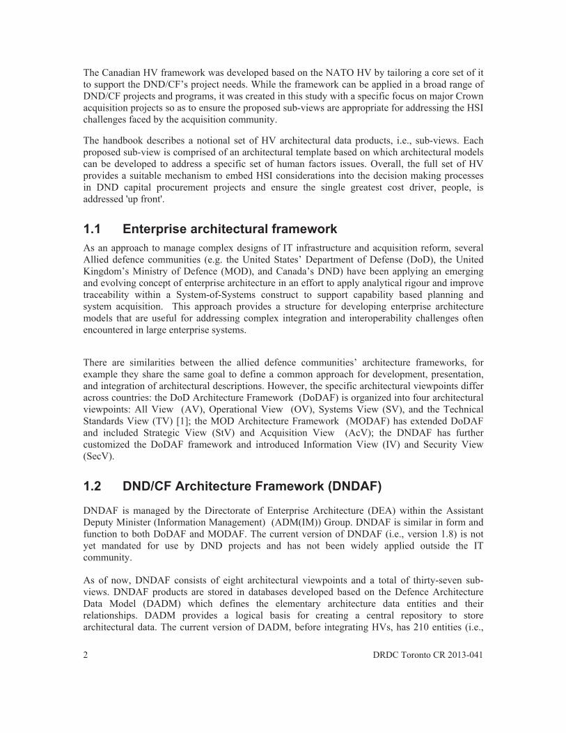
1.1 Enterprise architectural framework As an approach to manage complex designs of IT infrastructure and acquisition reform, several Allied defence communities (e.g. the United States’ Department of Defense (DoD), the United Kingdom’s Ministry of Defence (MOD), and Canada’s DND) have been applying an emerging and evolving concept of enterprise architecture in an effort to apply analytical rigour and improve traceability within a System-of-Systems construct to support capability based planning and system acquisition. This approach provides a structure for developing enterprise architecture models that are useful for addressing complex integration and interoperability challenges often encountered in large enterprise systems.
There are similarities between the allied defence communities’ architecture frameworks, for example they share the same goal to define a common approach for development, presentation, and integration of architectural descriptions. However, the specific architectural viewpoints differ across countries: the DoD Architecture Framework (DoDAF) is organized into four architectural viewpoints: All View (AV), Operational View (OV), Systems View (SV), and the Technical Standards View (TV) [1]; the MOD Architecture Framework (MODAF) has extended DoDAF and included Strategic View (StV) and Acquisition View (AcV); the DNDAF has further customized the DoDAF framework and introduced Information View (IV) and Security View (SecV).
1.2 DND/CF Architecture Framework (DNDAF)
DNDAF is managed by the Directorate of Enterprise Architecture (DEA) within the Assistant Deputy Minister (Information Management) (ADM(IM)) Group. DNDAF is similar in form and function to both DoDAF and MODAF. The current version of DNDAF (i.e., version 1.8) is not yet mandated for use by DND projects and has not been widely applied outside the IT community.
As of now, DNDAF consists of eight architectural viewpoints and a total of thirty-seven sub-views. DNDAF products are stored in databases developed based on the Defence Architecture Data Model (DADM) which defines the elementary architecture data entities and their relationships. DADM provides a logical basis for creating a central repository to store architectural data. The current version of DADM, before integrating HVs, has 210 entities (i.e.,

DRDC Toronto CR 2013-041 3
data tables) and 1229 data attributes (i.e., fields). To assist the modelling effort, DEA is currently implementing DNDAF in Qualiware which is a commercial software tool for enterprise architecture development.
1.3 Human View (HV)
Through the development and use of the above mentioned architecture frameworks, there was a general acknowledgement that the human element was not well represented in the existing framework. Earlier attempt was made to characterize the human dimension as a part of operational requirements and use several OV sub-views to describe humans’ role and their operational activities [1]. However to most Human Factors (HF) practitioners, such solutions are not comprehensive and do not represent the wide spectrum of human related issues that should be considered in enterprise architectural modeling. An independent architectural viewpoint, i.e., the HV, was recommended as a preferred solution and the notion triggered research interests from the HF communities from several allied nations including Canada.
The initial Canadian effort focused on personnel issues in Human Resources (HR) management and proposed four sub-views (i.e., Manpower Projection, Career Progression Roadmap, Individual Training Roadmap, and Establishment Inventory) to support common decisions faced by the HR community [8]. This set of sub-views was later integrated into the NATO HV framework which was created with an expanded goal to support a wider range of enterprise stakeholders including system designers and developers (e.g., HF engineers). The purpose of the current study was to Canadianize the NATO HV framework and customize a core set of HV based on DND/CF project needs.
1.4 NATO HV framework
The NATO HV was generated by the NATO Research and Technology Organization (RTO) Human Factors and Medicine (HFM) work panel 155. This research group took inputs from participating nations and established a set of HV sub-views by first grouping human characteristics into related themes, and then consolidate the themes into a manageable set of architectural constructs. The following set of eight sub-views was proposed. The readers are referred to the NATO HV handbook for more information [7].
- HV-A Concept - HV-B Constraints - HV-C Tasks - HV-D Roles - HV-E Human Network - HV-F Training - HV-G Metrics - HV-H Human Dynamics
1.5 Approach to Tailoring the NATO HV
The NATO HV framework reflects a high-level conceptual outline that requires further customization by architecture modellers to select the form and format for architectural

4
descriplethoengindifficu
With CanadexamiSeconfive dhumasuppolevelsappro
1.6
The afor prconceeffectSympcriticadefenHSI ismanagHSI cmaint
WithiHuma
iptions. Suchora of HSI ceering. On thult to generat
a focus to sudian HV. Firined and utilind, the HV wdomains inclun factors eng
ort HV devels of informaoaches, the rea
Alignm
authors suggesromoting the ept of HSI arotiveness. As nposium on Mal system coce problems s to consider ging MA&S
can contributetainability, av
in the DND, an Factors E
h flexibility concepts and he other handte standardize
upport DND rst, a user-ceized as the p
was closely aluding manpogineering. Thlopment decisation granulaaders are refe
ment betw
sted a close aadoption of
ose from a genoted in the
Man as the Liomponent and
[9]. In the dhuman perfoactivities to
e to system efvailability and
Figure 1
HSI is definEngineering, M
allows HF passisting dec
d, the lack oed architectura
acquisition, tentred approrimary criteriligned with thower and perhird, project dsions such as
arity. For detrred to a sepa
ween Can
lignment of thenterprise arceneral recognconclusion o
imiting Elemed technologicomain of Marmance factoseek an impr
ffectiveness ind survivability
1: Conceptual
ned as the tecManpower a
practitionerscision-makingf specificity al description
this project tach was takion for justifyhe Canadian rsonnel, traindata from DNs the form antailed accoun
arate report pr
nadian HV
he Canadian chitecture as
nition of the iof the 1983 Nent in Militacal solutionsateriel Acquisors together wrovement in on many areasy.
l illustration o
chnical procend Personne
to create HVg in the lifecin the NATO
ns that are com
took a pragmken and stakefying the need
HSI framewning, system ND use case
and format ofnt of the dereviously pub
V and HS
HV with the a method am
importance oNATO Defenary Systems, hs alone woulsition and Su
with system efoverall system
s including op
of Canadian H
ess of integrael, Training,
DRDC Toron
V models focycle of systO HV framewmparable acro
matic approacheholder requd for a partic
work that is chsafety, healt
s were extenf architecturaevelopment pblished [1].
SI framew
HSI framewomong HF praf Human Fac
nce Research human was ildn’t be ableupport (MA&ffectiveness mm performanperability, saf
HSI.
ating the five System Safet
nto CR 2013-04
or analyzingtem-of-systemwork makes oss projects.
h to create thuirements wercular sub-viewharacterized oth hazard, annsively used tal descriptionprinciples an
work
ork was criticactitioners. Thctors in systemGroup (DRG
identified as e to solve ou
&S), the gist omeasures whince. In generafety, reliability
HSI domainty, and Healt
41
a ms
it
he re w. of nd to
ns, nd
al he m
G) a
ur of le al, y,
ns, th
DRDC Toronto CR 2013-041 5
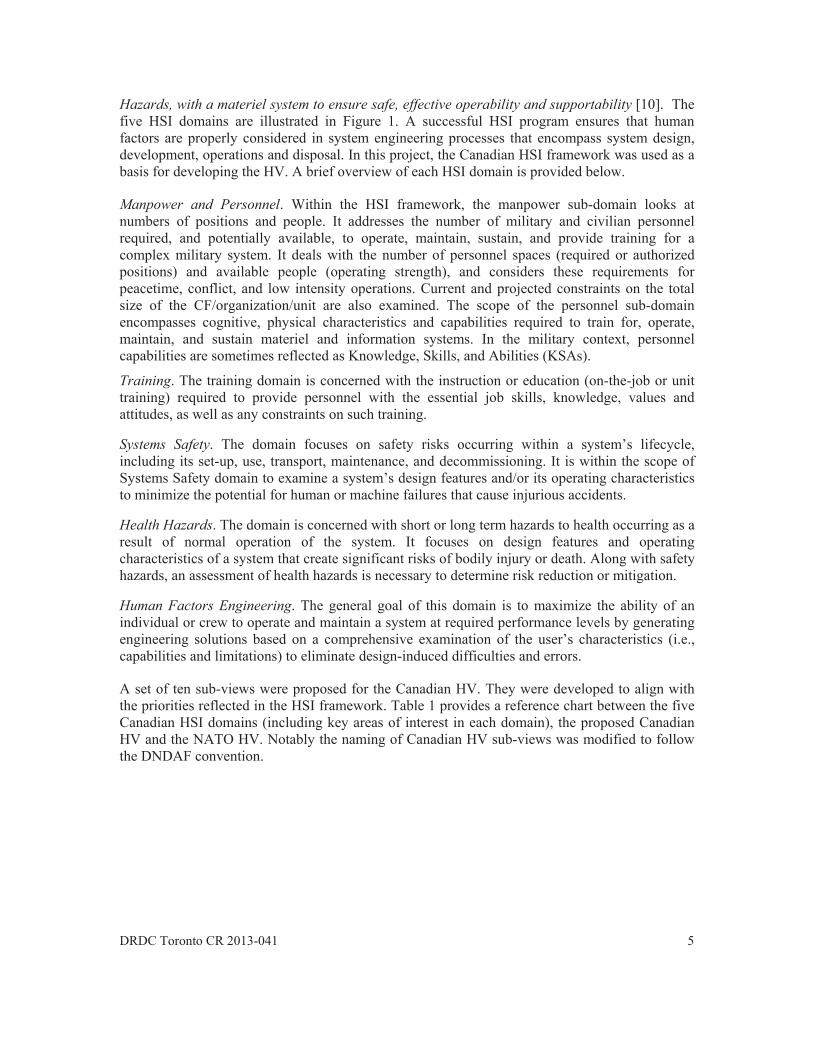
Hazards, with a materiel system to ensure safe, effective operability and supportability [10]. The five HSI domains are illustrated in Figure 1. A successful HSI program ensures that human factors are properly considered in system engineering processes that encompass system design, development, operations and disposal. In this project, the Canadian HSI framework was used as a basis for developing the HV. A brief overview of each HSI domain is provided below.
Manpower and Personnel. Within the HSI framework, the manpower sub-domain looks at numbers of positions and people. It addresses the number of military and civilian personnel required, and potentially available, to operate, maintain, sustain, and provide training for a complex military system. It deals with the number of personnel spaces (required or authorized positions) and available people (operating strength), and considers these requirements for peacetime, conflict, and low intensity operations. Current and projected constraints on the total size of the CF/organization/unit are also examined. The scope of the personnel sub-domain encompasses cognitive, physical characteristics and capabilities required to train for, operate, maintain, and sustain materiel and information systems. In the military context, personnel capabilities are sometimes reflected as Knowledge, Skills, and Abilities (KSAs).
Training. The training domain is concerned with the instruction or education (on-the-job or unit training) required to provide personnel with the essential job skills, knowledge, values and attitudes, as well as any constraints on such training.
Systems Safety. The domain focuses on safety risks occurring within a system’s lifecycle, including its set-up, use, transport, maintenance, and decommissioning. It is within the scope of Systems Safety domain to examine a system’s design features and/or its operating characteristics to minimize the potential for human or machine failures that cause injurious accidents.
Health Hazards. The domain is concerned with short or long term hazards to health occurring as a result of normal operation of the system. It focuses on design features and operating characteristics of a system that create significant risks of bodily injury or death. Along with safety hazards, an assessment of health hazards is necessary to determine risk reduction or mitigation.
Human Factors Engineering. The general goal of this domain is to maximize the ability of an individual or crew to operate and maintain a system at required performance levels by generating engineering solutions based on a comprehensive examination of the user’s characteristics (i.e., capabilities and limitations) to eliminate design-induced difficulties and errors.
A set of ten sub-views were proposed for the Canadian HV. They were developed to align with the priorities reflected in the HSI framework. Table 1 provides a reference chart between the five Canadian HSI domains (including key areas of interest in each domain), the proposed Canadian HV and the NATO HV. Notably the naming of Canadian HV sub-views was modified to follow the DNDAF convention.

6 DRDC Toronto CR 2013-041
Table 1: Human View Reference Chart.
HSI Domain Areas of interest Canadian HV NATO HV HV-1 Concept HV-A Concept
Manpower and Personnel
Force structure HV-2 Establishment HV-D Roles
Human Interaction HV-3 Organization HV-E Human network
Availability HV-4 Manpower projection HV-B1 Manpower projections
Previous experience and training
Not applicable HV-B2 Career progression
Cognitive and physical personnel factors
HV-5 Personal Characteristics
HV-D Roles and HV-B6 Human characteristics
Recruitment, retention, advancement
Not applicable 1 HV-B4 Personnel policy
Training Training HV-6 Training needs HV-F Training
System Safety Systems Safety HV-7 System safety HV-B5 Health hazards Health Hazards
Health Hazards HV-8 Health hazards HV-B5 Health hazards
Human Factors Engineering
Operator roles, functions, and tasks
HV-9 Human tasks HV-C Tasks
Operator roles, functions, and tasks
HV-10 Communications HV-E Human network
Environment Not applicable Not applicable
Workload Not applicable HV-H Human dynamics 2
Note 1: Several NATO HV are addressed within DND by Military Policy, Doctrine, Occupational Structure, and Job Descriptions which are all legal descriptions governing both Military and Civilian employees of the Department of National Defence, and are not considered applicable as Canadian HVs. Note 2: The NATO description, and intent, for HV-H (Human dynamics) identifies it as a place to perform dynamic analysis, using data from various other HV, typically executed using tools external to the architecture framework. Thus the Human Dynamics View represents the possibilities brought to bear by completing good Human Factors analysis, however, this analysis and the reporting of results are best served by being maintained outside the confines of an architecture framework.
DRDC Toronto CR 2013-041 7
2 The Canadian Human View
The proposed Canadian HV framework is comprised of ten sub-views. Section 2 provides a detailed description for each sub-view, following a similar structure that was used in DADAF user’s guide for defining other architectural viewpoints. More specifically, each sub-view is described from the following four aspects:
1. The purpose sub-section explains the intended utilities for the sub-view, including DND/CF stakeholders that can be identified as potential users of the sub-view;
2. The prerequisite sub-section attempts to describe the inter-dependency, at the architectural data element level, among different sub-views;
3. The instruction sub-section explains basic data elements proposed for the sub-view, and suggests a set of common steps that can be followed in a typical modeling effort; and
4. The representation sub-section provides one or more examples of architectural models developed based on the sub-view.
Most sample models provided in this section were obtained from past DND use case studies, particularly the conceptual design of a Virtual-Combined Aerospace Operations Centre (V-CAOC). It is useful to note that the models are reported for illustrative purposes, and the data have not been endorsed by DND. Additionally, most sample models are self-explanatory. In a few cases where contextual information is needed for interpreting the models, brief commentaries are provided.
2.1 HV-1 Concept
HV-1 (Concept) is a high-level pictorial depiction of the human element in an enterprise architectural model. It serves as a single point of reference to illustrate key HSI concepts, e.g., the HF design challenges and/or solutions, that the HV architecture models are created to support.
2.1.1 Purpose
The purpose of HV-1 is to provide a conceptual overview of the human dimension in the enterprise. Similar to the utility of OV-1 (High-level operational concept diagram), HV-1 is useful for presentation and discussion purposes. For example, a practical usage of HV-1 is in project briefings where an HV-1 model can be inserted into a standard DND project update quad-chart presentation to describe the HSI concept to various stakeholders.
Generally speaking, the sub-view should highlight the human element and its interdependent relationship with other enterprise factors such as technology, infrastructure and business processes. Ideally, the content of HV-1 should be tailored to indicate key HSI concerns for the architecture modeling project. As such it is typically up to the architecture developer to determine the specific messages to be conveyed in this sub-view. One example is to use HV-1 for depicting

8 DRDC Toronto CR 2013-041
HSI concepts in relation to operational demands and system solutions that are captured in the associated OV and SV models respectively.
2.1.2 Prerequisite
If OV-1 (High-Level Operational Concept Graph) is available, it should be reviewed before the development of an HV-1 model. OV-1 depicts the Concept of Operations for the enterprise of interest, based on which an HV-1 model can be generated to further highlight those concepts where the key enabler is people.
2.1.3 Instruction The “look and feel” of an HV-1 model depends on the architect’s creativity. As a general rule of thumb, it is recommended that the following steps should be considered in the model construction process.
1. Determine key HSI concepts that are applicable to the enterprise of interest. This can be performed by reviewing the OV-1 model (if it is available) to identify operational concepts where the enabler is the human factors;
2. Construct pictorial representations of the HSI concepts, and if possible, provide a visual reference to connect HV-1 and OV-1 models.
Multiple versions of HV-1 may be developed for an architecture project. As an enterprise evolves, so are its HSI concerns. Consequently the HV-1 should be modified to reflect the current areas of focus so as to continually support enterprise design and problem-solving.
2.1.4 Representation
Examples of HV-1 are shown in Figure 2, 3 and 4, reflecting models developed in two different projects. It is useful to note that a common solution was adopted in the examples by inserting a graphical reference to the Canadian HSI framework, at the top right corner, and accentuating the domains that were deemed relevant to the intended use of the architectural models.
Figure 2 was obtained from a Royal Canadian Navy (RCN) use case [2] in which the goal of HV models was to support crewing analysis. In this example, the architect used an HV-1 model for illustrating HSI concerns in the area of ship manning, that is, to determine the type and number of naval personnel required across major ship functions.

DRDC
Figurestudy architarchitenhanof CAHV-1associ
C Toronto CR 2
Figu
e 3 and 4 are on its Comb
tecture modetecture modelnce the globalAOC was avai
models and iation betwee
2013-041
ure 2: An HV
examples of bined Aerospael of the exil of a forwarl reach of the ilable (see Figcommon grap
en HSI concer
V-1 (Concept)
f HV-1 modelace Operationisting CAOCrd deployed V
existing CAOgure 5), it waphical elemenrns and opera
model for RC
ls developed fns Centre (CAC, whereas FVirtual CAOCOC [3]. In this reviewed prnts were adop
ational concep
CN ship crew
for a Royal CAOC). FigureFigure 4 refC (V-CAOC)is case, since rior to the devpted in the Hpts.
wing analysis.
Canadian Air e 3 is a baselflects a targe) unit that cathe associate
velopment of HV-1 models
Force (RCAFline (i.e., as-iet (i.e., to-bean be set up ted OV-1 modf correspondinto enhance th
9
F) s) e) to
del ng he

10
Figurre 3: A sample
Figure 4: A
e HV-1 (Conc
A sample HV
cept) model of
V-1 (Concept)
of the existing
model of V-C
DRDC Toron
g RCAF CAOC
CAOC.
nto CR 2013-04
C.
41
DRDC
Figu
2.2
HV-2enterpother
2.2.1
If onebasic indiviwith b
Essenunder
C Toronto CR 2
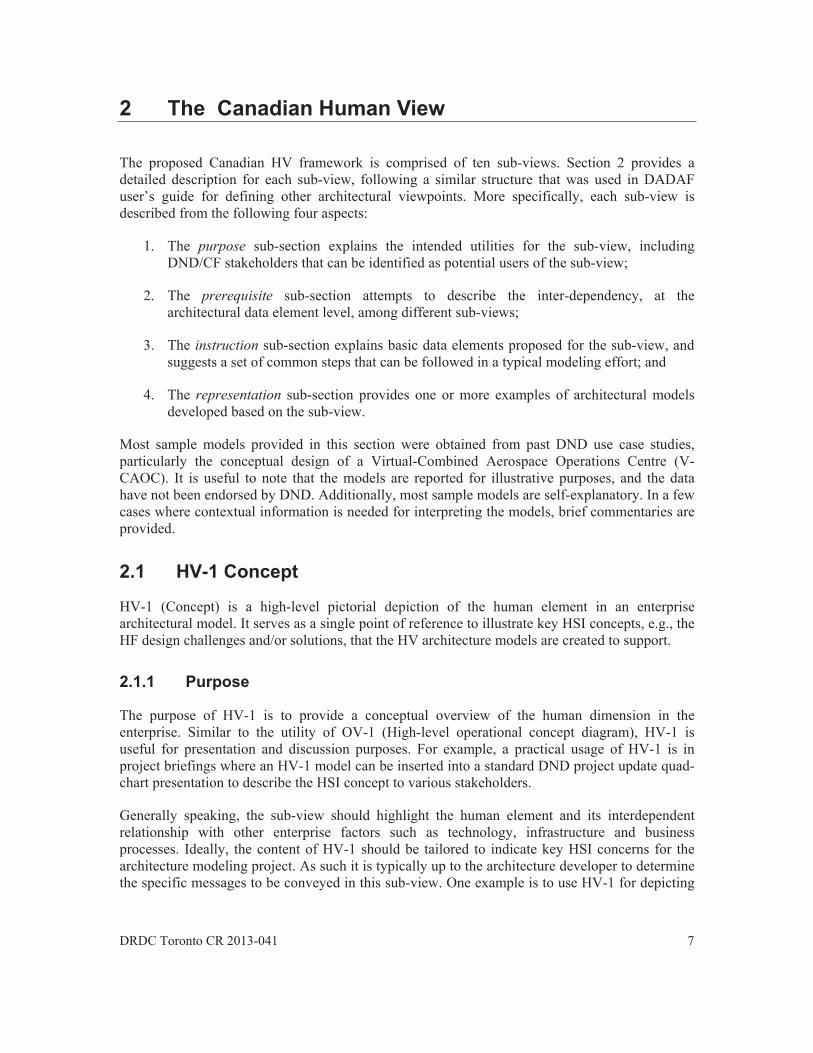
ure 5: An OV-
HV-2 E
2 (Establishmprise architectypes of prim
1 Purpo
e considers anelement of t
iduals are” inbasic descript
ntially a nomirstand the per
2013-041
-1 (High-level
Establish
ment) providescture model,
mary and supp
ose
n enterprise athe social aspn an enterpristions of their o
inal roll, an Hsonnel compo
l operational
hment
s a complete including fo
portive staff re
as a socio-techpect of the ense. The sub-voccupations a
HV-2 model iosition of the
concept grap
list of persor example opequired for en
hnical systemnterprise, i.e.,view providesand qualificat
is useful for aenterprise.
ph) model of C
onnel that neeperators, mainterprise oper
m, the purpose, individuals,s a complete tion levels.
any enterprise
CAOC (Adap
eds to be conintainers, trairations.
e of HV-2 is , and documelist of enterp
e stakeholder
1
ted from [4])
nsidered in thiners, and an
to describe thent “who thesrise personne
r who wants t
11
.
he ny
he se el,
to

12 DRDC Toronto CR 2013-041
2.2.2 Prerequisite
There are no prerequisite sub-views for HV-2, since the construction of a HV-2 model does not directly require architectural data from other sub-views. However, it is recommended that the logical process to determine enterprise manning should start with an examination of human tasks.
2.2.3 Instruction
A definition of key architectural data elements in the HV-2 is provided below:
Establishment: A listing of the people who work in a structured (e.g., hierarchical) organization to support shared enterprise objectives.
Position: The smallest part of a personnel establishment that requires the work of one individual. A position exists whether it is occupied or vacant and is the basic accounting unit for personnel planning and control activities.
Occupation: An occupation is the fundamental grouping of personnel used for the Human Resources cycle of activities. Each occupation comprises a grouping of related jobs having similar duties / tasks and requiring similar competencies. A job is defined as the work performed by a position incumbent, or by those in a group of similar positions requiring the incumbent(s) to successfully perform a similar set of tasks with their associated knowledge, skills, and abilities (KSA).
Qualification Level (QL) and Rank: QL is a description of the minimum knowledge and skills a CF member must possess before becoming eligible to progress to the next higher rank level. QL reflects the level of formal training expected to hold the designated position. In the CF, the QL and Rank are closely related. As an example a Naval Combat Information Operator (NCIOP) QL5A is a mandatory requirement for promotion to Leading Seaman (LS) and QL6A is required for promotion to Petty Officer Second Class (PO2). Note: civilian organizations often have similar structures, typically denoted as classification levels (e.g., Engineer Level 4), to group individuals with similar KSA.
The following steps are suggested for creating an HV-2 model:
1. Based on the scope of architecture project, determine who should be represented in this sub-view model. For example, address questions such as whether it is necessary to include the second or third order manpower requirements (i.e., maintainers, trainers, and other supporting staff) in the model;
2. Supply a list of positions required to support the enterprise functions; 3. For each position, assign a basic set of core attributes such as Rank, MOSID, and QL.
For civilian positions, a corresponding set of attributes like classification and level are used instead.
DRDC Toronto CR 2013-041 13
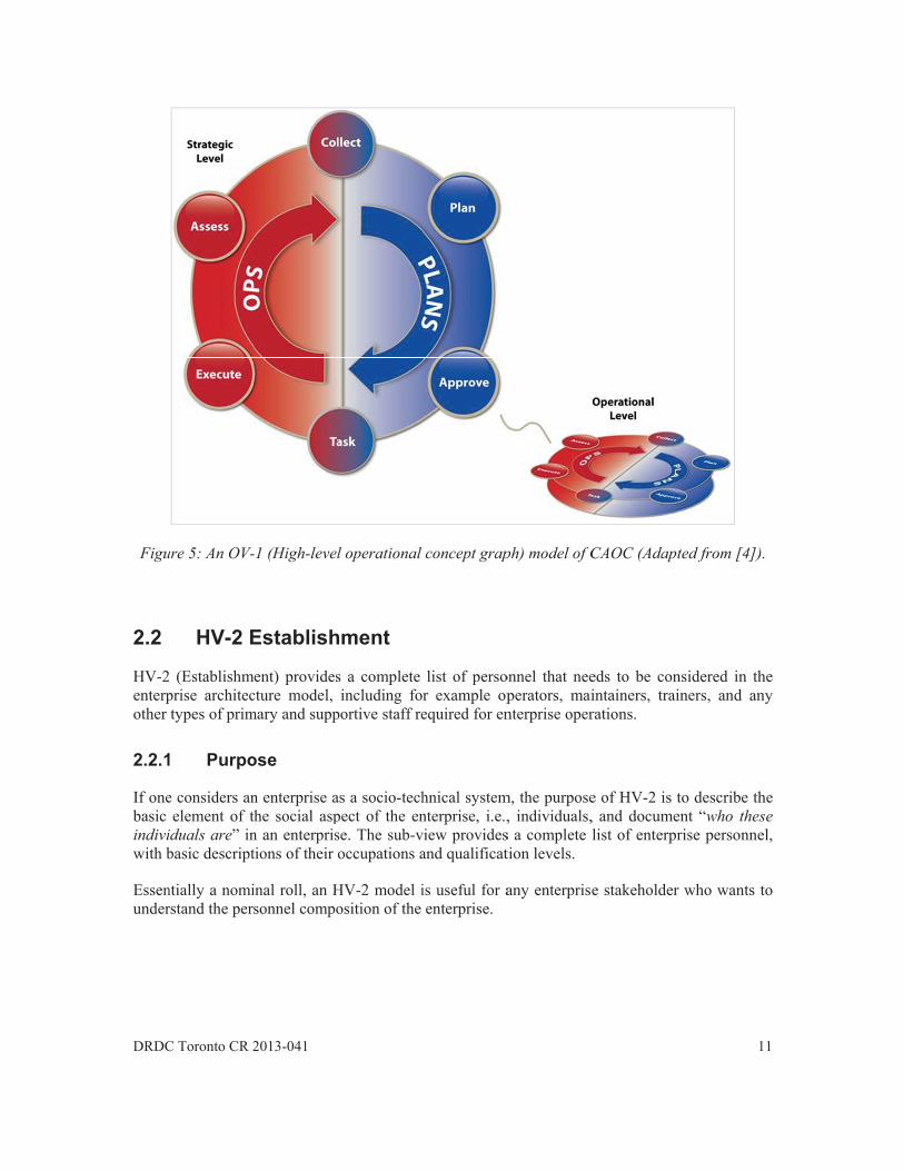
2.2.4 Representation
The HV-2 is envisioned to use a tabular representation in which a list of personnel is presented in a data table. Three examples of HV-2 models were obtained from RCAF’s V-CAOC study to reflect three V-CAOC configurations with different personnel footprint, as shown in Table 2, 3 and 4 respectively. For this analysis, it was determined that the scope of HV-2 was limited to the forward deployed V-CAOC team, excluding the existing CAOC personnel that are responsible for carrying out regular CAOC functions.
Table 2: A sample HV-2 (Establishment) model for V-CAOC (Minimum manning)
ID # Position Rank Occupation (MOSID) 1 V-CAOC Director LCol Any Air Occupation Officer 2 Chief Operations Maj Any Air Occupation Officer 3 Combat SO Ops 1 Capt/Maj Any Air Occupation NCM 4 Combat Ops Sup Capt Any Air Occupation Officer 5 SODT Lead Capt Any Air Occupation Officer 6 ATO Production MCpl/Cpl Any Air Occupation NCM 7 ISRD Capt 00213 Intelligence Officer 8 Analysis and Production MCpl/Cpl 00099 Intelligence Operator 9 Analysis and Production MCpl/Cpl 00099 Intelligence Operator 10 ISR Ops Capt 00213 Intelligence Officer
Table 3: A sample HV-2 (Establishment) model for V-CAOC (Medium manning)
ID # Position Rank Occupation (MOSID) 1 V-CAOC Director LCol Any Air Occupation Officer 2 V-CAOC Deputy Director Maj Any Air Occupation Officer 3 Chief Operations Maj Any Air Occupation Officer 4 Plan A3/A5 Capt Any Air Occupation Officer 5 Plan A3/A5 Capt Any Air Occupation Officer 6 Combat Ops Sup Capt/Maj Any Air Occupation Officer 7 SODT Lead Capt Any Air Occupation Officer 8 ATO Production MCpl/Cpl Any Air Occupation NCM 9 ISRD Capt/Maj 00213 Intelligence Officer 10 Analysis and Production MCpl/Cpl 00099 Intelligence Operator 11 Analysis and Production MCpl/Cpl 00099 Intelligence Operator 12 ISR Ops Capt 00213 Intelligence Officer 13 ISR Ops Capt 00213 Intelligence Officer 14 Chief Mission Support Maj 00328 Logistics15 Logistics Suport Capt 00328 Logistics16 Admin Support Capt 00328 Logistics17 Information System Support Capt/Maj 00340 Communications and
Electronics Engineering - Air

14 DRDC Toronto CR 2013-041
Table 4: A sample HV-2 (Establishment) model for V-CAOC (Maximum manning)
ID # Position Rank Occupation (MOSID) 1 V-CAOC Director LCol Any Air Occupation Officer 2 V-CAOC Deputy Director Maj Any Air Occupation Officer 3 CAOC LO Capt Any Air Occupation Officer 4 CAOC NAPPIC/ATO MCpl/Cpl Any Air Occupation NCM 5 D/ACCEs Maj/Capt Any Air Occupation Officer 6 D/ACCEs Maj/Capt Any Air Occupation Officer 7 Airspace Coord Maj/Capt 00184 Aerospace Control 8 Plan A3/A5 Capt Any Air Occupation Officer 9 Plan A3/A5 Capt Any Air Occupation Officer 10 Plan A3/A5 Capt Any Air Occupation Officer 11 Plan A3/A5 Capt Any Air Occupation Officer 12 Plan A3/A5 Capt Any Air Occupation Officer 13 ISRD Capt/Maj 00213 Intelligence Officer 14 Collator MCpl/Cpl 00099 Intelligence Operator 15 Collator MCpl/Cpl 00099 Intelligence Operator 16 ISR Ops Capt 00213 Intelligence Officer 17 ISR Ops Capt 00213 Intelligence Officer 18 Chief Mission Support Maj 00328 Logistics19 Logistics Suport Capt 00328 Logistics20 Finance Support Capt 00328 Logistics21 Personnel Support Capt 00328 Logistics22 CE Support Capt 00189 Airfield Engineering 23 Information System Support Capt/Maj 00340 Communications and
Electronics Engineering - Air 24 Technical Information
Support (TIS) WO 00109 Aerospace Telecommunications
Technician
2.3 HV-3 Organization
HV-3 (Organization) depicts the organization of all individuals (as specified in HV-2) in the enterprise of interest. It describes the formal organizational reporting structure, from which information such as chain-of-command and organizational grouping can be obtained.
Compared with the current DNDAF, HV-3 overlaps significantly with OV-4a (Organizational Relationship Chart). Both are intended to display the organizational relationships in an enterprise. One distinction can be made based on how the personnel element is defined in the graphical representation. HV-3 specifies each individual should be represented in this sub-view, whereas it is acceptable in OV-4a to describe the organizational configuration at the functional grouping level (i.e., divisions or units). The authors recognize such a distinction is rather minor and it is feasible to merge these two sub-views while integrating the HV into DNDAF. In this handbook, HV-3 is explicitly proposed for the sake of completeness when presenting the HV framework.

DRDC
2.3.1
The passocithe punderinter-rview t
2.3.2
HV-2person
OV-4develo
2.3.3
The benterpfour g
Figurestudydivisi
C Toronto CR 2
1 Purpo
purpose of HViated HV-2 mpositions defrstanding of frelationships to describe th
2 Prereq
2 (Establishmnnel that need
4a (Organizatopment of a H
3 Instru
basic informaprise and persgraphical elem
A diamond
A hexagonenterprise.number of
A rectanguindividual as the posi
A stackedassignmenthat shares
Figure 6: Su
e 7 illustrate. Specificallyon is compris
2013-041
ose
V-3 is to depmodel. In othefined in theformal functiamong the i
he size of diff
quisite
ment) is a preds to be repre
ional RelatioHV-3 model c
uction
ation requiredsonnel assignmments are sugg
d shaped elem
nal element th A numeric v
f personnel in
ular shape repcan use the u
ition descripto
d rectangularnt. A numerics the same dut
uggested grap
s how these y, the enterprsed of eight m
ict the structuer words, inde correspondional groupinindividuals. Nferent organiz
erequisite subesented in the
onship Chart)can be consid
d for an HV-ment in this sgested, as illu
ment that indic
hat representsvalue in the bthe this organ
presents a sinunique identifor or the ident
r shape repr indicator atties and respo
phical elemen
graphical elerise of intere
members; Con
ure and organdividuals presding HV-2ngs of peopleNumerical indational group
b-view for HHV-3 organi
should be rdered as an ex
3 model inclstructure. To dustrated in Fig
cates the over
s a subdivisiobottom right cnizational gro
ngle individuafication availatification num
resents multithe bottom ri
onsibilities.
ts for depictin
ements manifest in this canstruction En
nization of alsented in HVmodel. This
e in the entedicators are a
pings.
HV-3. It proizational diag
reviewed if thxtension of OV
ludes the orgdepict such agure 6:
rall enterprise
on or organizcorner of the oup;
al in the enterable in the as
mber.
iple individuight corner sh
ng an HV-3 (
fest themselvase is the CA
ngineer Missio
ll personnel sV-3 can be dir
s sub-view erprise and thalso suggeste
ovides the cogram.
he model is V-4a to the in
ganizational sa structure in a
e;
zational grouphexagon ind
rprise. The lassociated HV-
uals with thhows the num
(Organization
ves in the CAAOC; its Mion Support (C
1
specified in threctly traced t
facilitates ahe hierarchiced in this sub
omplete list o
available. Thndividual leve
tructure of tha HV-3 mode
ping within thdicates the tot
abeling of eac-2 model, suc
he same wormber of peop
n) model.
AOC modelinission SuppoCE Msn Spt)
15
he to an al b-
of
he el.
he el,
he tal
ch ch
rk le
ng ort is

16
an indSpt) c
The fo
1.2.3.4.
2.3.4
HV-3Figurereducindicacontraand th
dividual (withconsists of tw
Figure 7:
following step
. Obtain fun
. Obtain per
. Assign per
. Create a chorganizatio
4 Repre
is envisionede 9 to show ed ‘as-is’ HVate the minimasting these twhe forward de
hin the Misso persons.
The HV-3 gr
ps are suggest
nctional grouprsonnel positirsonnel positihart diagram uonal structure
esentation
d to use a gramodels dev
V-3 model of tmal manningwo models, i
eployed team.
ion Support
raphical eleme
ted for creatin
pings of the oons from the ions to each ousing the sug
e of the enterp
aphical represeveloped for ththe existing Cg configuratiit is possible
division); an
ents, as manif
ng an HV-3 m
rganization frcorrespondin
of the functionggested graphiprise.
entation. Twohe CAOC anCAOC, and Fion for the fto analyze th
nd Logistics M
ifested in a DN
model:
from the correng HV-2 modnal groupingsical elements
o examples arnalysis. Spec
Figure 9 is oneforward dep
he functional
DRDC Toron
Mission Supp
ND use case s
esponding OVel;
s; and to represent
re presented icifically, Figue of the “to-bloyed V-CAinterfacing b
nto CR 2013-04
port (Log Ms
study.
V-4a model;
the
in Figure 8 anure 8 reflect be” models th
AOC team. Between CAO
41
sn
nd a
at By OC

DRDC
C Toronto CR 2
Figure 8: A
2013-041
sample HV-33 (Organizatio
on) model forr CAOC (the rreduced as-is
1
s model).
17
18 DRDC Toronto CR 2013-041
Figure 9: A sample HV-3 (Organization) for V-CAOC (the to-be model for the minimal manning
configuration).
2.4 HV-4 Manpower projection
HV-4 (Manpower projection) provides a forecast of manpower requirement for the modelled enterprise over a time line that is defined according to the purpose of architecture project. While HV-2 reflects a manpower prediction based on the enterprise functional requirements, HV-4 provides more detail by projecting such requirements along a time horizon and describes when the personnel resources will be required and how the demand will fluctuate as the enterprise goes through different phases. An extreme example of the projection time line is the entire life cycle of an enterprise. Together these two sub-views supply essential architectural data for enterprise crewing analysis.
2.4.1 Purpose
The purpose of HV-4 is to provide a temporal forecast of personnel requirements for an enterprise based on anticipated operational demands. The sub-view is important for stakeholders that are involved in HR planning activities such as recruiting, training, professional development, personnel assignment and management.

DRDC Toronto CR 2013-041 19
2.4.2 Prerequisite
HV-2 (Establishment) is a prerequisite sub-view for HV-4 and supplies a repository of personnel required by the enterprise.
CapV-1 (Capability Taxonomy) provides useful information for constructing the timeline for manpower forecast. CapV-1 describes important enterprise capability states, such as Initial Operational Capability (IOC), Full Operational Capability (FOC), and System Disposal. These capability states reflect major milestones in an enterprise’s life-cycle and often have specific implications on manpower demand. One solution for HV-4 is to align manpower forecast with these capability states. It is useful to note however that other types of milestones can also be adopted (e.g., specific operations and exercises) as long as these events lead to a change of personnel requirements.
2.4.3 Instruction
The proposed architecture data elements for HV-4 include:
Enterprise state descriptor, e.g., capability milestones that cause a significant change of manpower requirements;
Timing information for each enterprise state, which describes when a change of manpower requirement are expected; and
Manpower requirements associated with each enterprise state.
Currently in this sub-view, the forecast is made at the individual level. The information can be aggregated to infer the number of people required for specific personnel types (e.g., MOSID and QL).
The following steps are suggested for creating an HV-4 model:
1. Identify enterprise states against which manpower forecast is required. Use information from CapV-1 if enterprise capability states are accepted as preferred state descriptors;
2. Provide a start (and optionally, an end) date for each enterprise state; and 3. Based on the personnel repository that is defined in the corresponding HV-2 model,
specify the type and number of personnel required for each enterprise state.
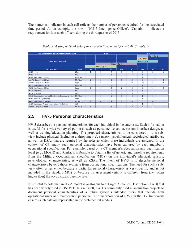
2.4.4 Representation
HV-4 is envisioned to use a tabular representation. A sample model is provided in Table 5 that illustrates manpower projection for a V-CAOC team during the period between 2013 and 2014. This example shows personnel requirements, described in terms of occupation and rank, in this time frame based on the RCAF’s operation requirements that serve as capability states driving the manning demand.
20 DRDC Toronto CR 2013-041
The numerical indicator in each cell reflects the number of personnel required for the associated time period. As an example, the row – ‘00213 Intelligence Officer’, ‘Captain’ – indicates a requirement for four such officers during the third quarter of 2013.
Table 5: A sample HV-4 (Manpower projection) model for V-CAOC analysis.
2.5 HV-5 Personal characteristics
HV-5 describes the personal characteristics for each individual in the enterprise. Such information is useful for a wide variety of purposes such as personnel selection, system interface design, as well as training/education planning. The proposed characteristics to be considered in this sub-view include physical (including anthropometric), sensory, psychological, sociological attributes, as well as KSAs that are required by the roles to which these individuals are assigned. In the context of CF, many such personal characteristics have been captured by each member’s occupational specification. For example, based on a CF member’s occupation and qualification level (e.g., MOSID and Rank), it is feasible to obtain a list of generic and baseline requirements from the Military Occupational Specification (MOS) on the individual’s physical, sensory, psychological characteristics, as well as KSAs. The intent of HV-5 is to describe personal characteristics beyond those available from occupational specifications. The need for such a sub-view often arises either because a particular personal characteristic is very specific and is not included in the standard MOS or because its assessment criteria is different from (i.e., often higher than) the occupational baseline level.
It is useful to note that an HV-5 model is analogous to a Target Audience Description (TAD) that has been widely used in DND/CF. In a nutshell, TAD is commonly used in acquisition projects to document personal characteristics of a future system’s intended users that include both operational users and maintenance personnel. The incorporation of HV-5 in the HV framework ensures such data are represented in the architectural models.
Min. Op 4
Occupation Rank 1Q 2Q 3Q 4Q 1Q 2Q 3Q 4Q00183 Pilot LCol 1 2 2 1 2 3 2 100183 Pilot Maj 2 2 2 3 1 100184 Aerospace Control Maj/Capt 1 1 1Any Air Occupation Officer Maj/Capt 2 3 3 1 3 6 4 2Any Air Occupation Officer Capt 2 5 5 3 9 10 8 200213 Intelligence Officer Maj/Capt 1 1 1 2 1 100213 Intelligence Officer Capt 2 4 4 2 4 6 4 200328 Logistics Maj 1 1 1 2 1 100328 Logistics Capt 2 2 2 5 3 300340 Communications and Electronics Engineering Air Maj/Capt 1 1 1 2 1 100189 Airfield Engineering Capt 1 1 100099 Intelligence Operator MCpl/Cpl 2 4 4 2 4 6 4 200109 Aerospace Telecommunications Technician WO 1 1 1Any Air Occupation NCM MCpl/Cpl 1 2 2 1 2 3 2 1
Operational Demand
2013 2014Virtual Combined Aerospace Operations CentreMin. Op 5
Max. Op 3Med. Op 2
Min. Op 1

DRDC Toronto CR 2013-041 21
2.5.1 Purpose
The purpose of HV-5 is to specify personal characteristics, beyond those derivable from military occupational specifications, based on each individual’s job performance requirements. Such characteristics can be classified into the following categories:
Physical Characteristics, that is, physical and psychomotor skills (e.g., speed of typing, response time to visual and auditory signals, manual dexterity skills), anthropometric and medical traits (e.g., strength, body size, weight, health), biomechanical attributes (e.g., mechanical properties of joints; human posture).
Physiological/psychological characteristics, such as fitness levels, heat tolerance, lung capacity, working memory capacity, cognitive skills.
Sensory characteristics, including visual and auditory abilities such as field of vision, visual response to colour, and hearing sensitivity.
Knowledge, skills and abilities, such as communication skills, managerial skills, emotional stability, multi-tasking skills, generic and technical qualifications (e.g., computer literacy).
It is important to note that the list of characteristics is not exhaustive, other personal attributes can be added based on the needs of a specific architecture project. As an example, personality traits or demographic information (such as gender, age) can be incorporated into this sub-view if they are deemed important for enterprise decision-making. Additionally it is typical that a subset of the abovementioned characteristics is useful for a particular architecture modeling project, therefore we suggest it is the responsibility of the architect to determine and select the relevant attributes for inclusion in an HV-5 model.
2.5.2 Prerequisite
Information required for modelling HV-5 can be obtained from the following sub-view models:
HV-2 (Establishment) provides the list of enterprise personnel whose personal characteristics need to be specified;
HV-9 (Human tasks) supplies information regarding each individual’s task assignments, based on which personal characteristic requirements can be derived.
2.5.3 Instruction Personal characteristics can be described in a variety of ways. Some can be measured using a ratio scale while others are better assessed categorically. Table 6 provides an example how assessment criteria can be created to focus on requirements beyond those specified by an individual’s MOS. Following this scheme, personal characteristics can be evaluated using a binary (yes/no) response.

22 DRDC Toronto CR 2013-041
Table 6: Sample data elements, including personal characteristics and their assessment criteria, for modeling an HV-5 (Personal characteristics).
Attribute Criteria Position The name of the position in the system being analyzed. Rank The rank level of the position. Occupation (e.g., MOSID)
The Military Occupational Structure Identification Code.
Strength Does the position require strength beyond that expected of the MOSID and rank designated for the position?
Fitness Does the position require a fitness level beyond that expected of the MOSID and rank designated for the position?
Endurance Does the position require endurance beyond that expected of the MOSID and rank designated for the position?
Confined spaces Will the position be expected to operate in a confined space? Right handedness Does the position require the operator / maintainer to be right handed?
Visual acuity Does the position require visual acuity beyond that expected of the MOSID and rank designated for the position?
Colour vision Does the position require colour vision beyond that expected of the MOSID and rank designated for the position?
Auditory acuity Does the position require auditory acuity beyond that expected of the MOSID and rank designated for the position?
Decision making Does the position require decision making capabilities beyond that expected of the MOSID and rank designated for the position?
Concentration Does the position require concentration capabilities beyond that expected of the MOSID and rank designated for the position?
Attitude Does the position require an attitude beyond that expected of the MOSID and rank designated for the position?
Sociability Does the position require sociability skills beyond that expected of the MOSID and rank designated for the position?
Language abilities Does the position require language capabilities (written, oral or both) beyond that expected of the MOSID and rank designated for the position?
The following steps are suggested for creating an HV-5 model:
1. Identify a list of personal characteristics that are relevant to the architecture project; 2. Determine how each characteristic should be measured in the model, for example,
whether a categorical binary response (yes/no) is sufficient or numerical rating scales are needed;
3. Identify a list of personnel (i.e., positions) from the associated HV-2 model for whom detailed personal characterization is required;
4. For each individual, specify the characteristic requirement for each attribute defined in Step 1 using the rating scale decided in Step 2.
2.5.4 Representation
HV-5 is envisioned to use a tabular representation. Table 7 shows a sample HV-5 model for describing personal characteristic requirements (as defined in Table 6) for all personnel in the

DRDC Toronto CR 2013-041 23
minimal manning configuration of a V-CAOC team. An additional ‘Remark’ field was added for storing any commentary note that the architect supplied for each position.
Table 7: A sample HV-5 (Personal Characteristics) model for V-CAOC
analysis (the Minimal manning configuration).
Position Rank MOSID
PhysicalCharacteristics
SensoryCharacteristics Psychological Characteristics
Remark
Strength
Fitness
Endu
rance
Confined
Space
RightH
ande
dness
VisualAcuity
Colour
Visio
n
Auditory
Decisio
nMaking
Concen
tration
Attitud
e
Sociability
Language
Ability
V CAOCDirector
LCol Air Ops No No Yes No No No No No Yes No No Yes No Long hours.Will need tosocialize withJoint Staff.
ChiefOperations
Maj Air Ops No No Yes No No No No No No No No No No Long hours
Combat SOOps 1
Capt/Maj
Air Ops No No Yes No No No No No No No No No No Long hours
Combat OpsSup
Capt Air Ops No No Yes No No No No No No No No No No Long hours.Small teamwill requireenhancedresponsibility.
SODT Lead Capt Air Ops No No Yes No No No No No Yes No Yes No No Heavyworkload andlong hours
ATOProduction
Cpl Air Ops No No Yes No No No No No No No Yes No No Heavyworkload andlong hours
ISRD Capt 00213Intel
No No Yes No No No Yes No Yes No Yes No No Heavyworkload andlong hours Colouredintelligenceproducts
Analysis andProduction
Cpl 00099Intel
No No Yes No No No Yes No Yes No Yes No No Long hours.Small teamwill requireenhancedresponsibility.Colouredintelligenceproducts
Analysis andProduction
Cpl 00099Intel
No No Yes No No No Yes No Yes No Yes No No Long hours.Small teamwill require

24 DRDC Toronto CR 2013-041
enhancedresponsibility.Colouredintelligenceproducts
ISR Ops Capt 00213Intel
No No Yes No No No No No No No Yes No No Heavyworkload andlong hours
Note: The characteristics that are selected as ‘yes’ represent those items that are beyond or exceed those expected for the Ranks and MOSIDdesignated for the position.
2.6 HV-6 Training needs
Within DND/CF, the Chief of Military Personnel (CMP) and Human Resources Civilian (HR-Civ) provide functional direction and guidance on all personnel management matters, including training. Policy manuals such as the Canadian Forces Individual Training and Education System (CFITES) describe the model and processes for managing individual training and education issues. In practice, such issues are commonly handled by career managers and occupational advisors in these organizations. According to CFITES, training issues are commonly handled within the framework of military occupations. For example, Occupational Specification Validation Board (OSVB) is often set up to manage the analysis of task and performance requirements for each military occupation. The output is presented in Job Based Occupation Specification (JBOS), which provides a baseline for generating training requirements. An introduction of novel tasks into an occupation or a change of task performance requirements typically will trigger assessment on training needs and the follow-up generation of training plans. The full process is well defined in CFITES, and OSVB has their specialized methods and tools to support its work. The intent of HV-6 is not to modify the existing management framework, rather it is to raise the visibility of this important HSI domain in enterprise architecture and ensure the perspective from such stakeholders as training officers is well represented in enterprise planning and problem-solving.
2.6.1 Purpose
The purpose for HV-6 is to identify gaps between an individual’s qualification, skills, experience and those required by his/her jobs. The focus of this sub-view is to document requirements beyond those specified in an individual’s occupational specification, such as, those caused by assignment of novel tasks due to the use of new equipment and/or higher performance requirements. Such information can be fed into future Training Needs Analysis and JBOS processes.
2.6.2 Prerequisite
Information required for modelling HV-6 can be obtained from the following sub-view models:
HV-2 (Establishment) provides the list of enterprise personnel whose training needs should be assessed;

DRDC Toronto CR 2013-041 25
HV-9 (Human tasks) supplies information regarding each individual’s task assignments, based on which task and performance requirements can be derived.
2.6.3 Instruction
Table 8 provides a list of the basic data elements for modeling HV-6.
Table 8: A list of data elements for an HV-6 (Training needs) model.
Data element Description Position The name of the position in the enterprise being analyzed. The information is
available from the corresponding HV-2 model. Rank/level The required rank level of the position. The information is available from the
corresponding HV-2 model. Occupation (e.g., MOSID)
The Military Occupational Structure Identification Code. The information is available from the corresponding HV-2 model.
Tasks/Sub-Tasks A list of the tasks a position incumbent is expected to conduct. The mapping between positions and tasks are available from the HV-9 model.
Qualification Any unique qualifications that are required to perform the tasks expected of the position. These can be written in either plain text by the analyst or they can be captured as either the military occupational qualifications (e.g., ADFR for a MARS Officer, MOSID 00207) or occupational specialty specifications (e.g., AEEG – Surface Ship Command).
Skill Any unique skills that will be required to perform the roles/tasks expected of the position beyond those expected for a person of the Rank/QL and MOSID.
Experience Any unique experience that will be required to perform the roles/tasks expected of the position beyond those expected for a person of the Rank/QL and MOSID.
The following steps are suggested for creating an HV-6 model:
1. Identify positions from the corresponding HV-2 model that new training needs assessment may be required;
2. Examine the associated HV-9 model, collate all task and sub-task requirements for each position; and
3. Specify qualification, skills and experience requirements for each position.
2.6.4 Representation
HV-6 is envisioned to use a tabular representation. A sample model is shown in Table 9 that depicts the qualification, skill and experience requirement for each position identified in a forward deployed V-CAOC team.

26 DRDC Toronto CR 2013-041
Table 9: An HV-6 (Training needs) model for V-CAOC analysis.
Position Rank MOSID Tasks Qualifications Skills Experience ACCE Director LCol Air Ops Command
Operations Intelligence Planning
AJGM – Joint Command and Staff Programme
Adaptability, Operational Planning, Strong Leadership, Decisiveness
Post-Command, Operational Planning Process, recent deployed operation, understanding of RCAF doctrine
Deputy ACCE Director (Churchill)
Maj Air Ops Operations Intelligence
Adaptability, Operational Planning, Strong Leadership, Decisiveness, Flying Supervisor Qualification
Wing Ops, RJTF ACCE, deployed HQ
Deputy ACCE Director (Inuvik)
Maj Air Ops Operations Intelligence
Adaptability, Operational Planning, Strong Leadership, Decisiveness, Flying Supervisor Qualification
Wing Ops, RJTF ACCE, deployed HQ
ACCE A2 Capt Air Intelligence Planning
ACC Training, AEUU, AEUX
Good verbal comms, Adaptability, Operational Planning,
Wing Ops Centre
ACCE A2 Collator
Cpl Air Intelligence Adaptability, motivated, attention to detail
ACCE A3 Capt/Maj Air Ops 00183 or 00182
Operations Planning ATO Production
Operational & Tactical Planning, Building Air Tasking Orders (ATO)
Air Operations, Flying Supervisor Position, CAOC, Recent Deployed Operation
ACCE A3/A5 (ACC)
Capt Air Ops 00183 or 00183
Planning ATO Production
Operational & Tactical Planning, Building Air Tasking Orders (ATO)
Air Operations, Flying Supervisor Position, CAOC, Recent Deployed Operation
ACCE A3/A5 (Churchill)
Capt Air Ops 00183 or 00184
Planning ATO Production
Operational & Tactical Planning, Building Air Tasking Orders (ATO)
Air Operations, Flying Supervisor Position, CAOC, Recent Deployed Operation
ACCE A3/A5 (Inuvik)
Capt Air Ops 00183 or 00185
Planning ATO Production
Operational & Tactical Planning, Building Air Tasking Orders (ATO)
Air Operations, Flying Supervisor Position, CAOC, Recent Deployed Operation

DRDC Toronto CR 2013-041 27
2.7 HV-7 System safety
HV-7 summaries safety related management and engineering tasks that are required to identify prominent and foreseeable risks that may lead to potential accidents or mishaps and threaten the function of the enterprise. Within DND/CF, the Director General Safety (D Safe G) provides oversight on System Safety issues. D Safe G is responsible for developing and administering a General Safety Program which meets the legislated requirements of the Canada Labour Code Part II and provides guidance and direction to reduce accidents, minimize personal suffering and financial losses, and contribute to the morale and well-being of all personnel. In an acquisition effort, System Safety concerns are important in design trade-off considerations. The development of HV-7 is to ensure such concerns are dealt with systematically and safety domain experts are engaged in the decision-making process.
2.7.1 Purpose
The purpose of HV-7 is to highlight critical system safety concerns in enterprise architecture and ensures these issues will be reviewed and assessed by safety domain experts in the enterprise development process. Since system safety management activities are often project-specific and the associated method and approach are well defined by DND/CF policy documents such as the General Safety Program, the intent of HV-7 is not to change existing practices or prescribe safety management solutions, rather to inform decision-makers where specialized system safety analyses are required. The development of an HV-7 model requires domain experts to identify System Safety analyses that are applicable to the project. The model also provides a tracking mechanism that allows the status of each System Safety task to be updated.
The utility of HV-7 is similar to the sub-view TV-2 (Standards Forecast). While TV-2 provides a list of technical standards applicable to the enterprise project, HV-7 is created with a focus to support reporting and tracking functions for System Safety related effort.
2.7.2 Prerequisite
There are no prerequisite sub-views for HV-7
2.7.3 Instruction
HV-7 specifies a list of System Safety tasks that are applicable to the enterprise. Table 10 shows a list of suggested data elements for describing each task. A complete list of System Safety tasks and their definitions are available in MIL-STD-882E: Department of Defense Standard Practice: System Safety [12].
Table 10: Suggested data elements for describing System Safety tasks in HV-7 (System safety).
Data element Description System Safety Task
The specific task related to system safety.

28 DRDC Toronto CR 2013-041
OPI Officer of Principle Interest. The individual or group responsible for the specific system safety task.
Date Started The start date of the task. Dated Completed The completion date of the task. Remarks Any remarks or comments related to the specific task. This can also contain
a link to the completed or draft document. The following steps are suggested for creating an HV-7 model:
1. Identify System Safety tasks that are applicable to the enterprise; 2. Specify an OPI for each task; 3. Schedule a planned start date for each task; and 4. Update the model with task completion date and remarks as required.
2.7.4 Representation
HV-7 is envisioned to use a tabular representation. A sample HV-7 model template is shown in Table 11 that illustrates a non-exhaustive list of System Safety tasks for a generic acquisition project.
Table 11: A sample HV-7 (System Safety) model template for a generic acquisition project.
System Safety Task OPI Date Remarks Start Complete System Safety Program Plan Hazard Management Plan Hazardous Materials Management Plan Preliminary Hazard List Preliminary Hazard Analysis Functional Hazard Analysis Preliminary System Safety Assessment Operating and Support Hazard Analysis Health Hazard Analysis Health Hazard Assessment Personnel Impact Assessment Report System Safety Case System Hazard Analysis Safety Compliance Assessment Report Hazard Management Assessment Report Explosives Hazard Classification Data

DRDC Toronto CR 2013-041 29
2.8 HV-8 Health hazards
HV-8 provides a summary of prominent and foreseeable factors that may cause reduced job performance, illness, injury, and disability for enterprise personnel. The sub-view highlights health hazard concerns in enterprise architecture and ensures these issues will be reviewed and assessed by health hazard domain experts in the enterprise decision-making process. The proposed sub-view identifies health hazards and their link to operator tasks, as well as the associated equipment systems. As a decision-support aid, the sub-view points out whether dedicated Health Hazard Assessment (HHA) is needed.
Within DND, D Safe G is the authority on issues related to health hazards and workplace safety. Two documents, the General Safety Program [15] and A DND/CF Hazardous Occurrence Investigator’s Guide [16], were used as the primary reference materials for the creation of HV-8.
2.8.1 Purpose
The purpose of HV-8 is to identify health hazards and their association with operator tasks and equipment systems. The sub-view supports HHA to achieve the goal of minimizing or mitigating both short and long term hazards to health that occur as a result of system operation, maintenance and support.
2.8.2 Prerequisite
HV-9 (Human tasks) contains information regarding operator tasks and supportive systems, and is a prerequisite sub-view for developing an HV-8 model.
2.8.3 Instruction
Table 12 shows the recommended data elements for HV-8. Hazard risks are classified into physical, chemical, electrical, biological, radiological, and environmental hazards, according to the General Safety Program and A DND/CF Hazardous Occurrence Investigator’s Guide. Assessment of each hazard is performed by examining both the frequency and the severity of hazard exposure. A set of commonly used assessment criteria is provided in Table 13. A risk assessment matrix is shown in Table 14, based on which different risk reduction strategies can be developed.
Table 12 : A description of the basic data elements for HV-8 (Health hazards)
Data element Description Task / Activity The task or activity that causes operator exposure to a health hazard.
The information is available from the associated HV-9 model. Equipment / System The required equipment or system for supporting the operator
task/activity. The information is available from the associated HV-9 model.
Physical Hazard Collision, caught in or between equipment, falls, slips, trips,

30 DRDC Toronto CR 2013-041
Data element Description submersion, acoustical energy such as steady-state noise, impulse noise and blast over pressure, explosion, vibration, heat or cold stress, optical hazards, shock, repetitive strain and trauma.
Chemical hazards Hazardous materials that are flammable, explosive, corrosive, toxic, carcinogens or suspected carcinogens, systemic poisons, asphysxiants including oxygen deficiencies and respiratory irritants.
Electrical Hazards Electro static discharge, electrical fires, power loss, shock, short circuit and electromagnetic.
Biological hazards Pathogenic micro-organisms or bacteria. Radiological Hazards Ionizing and non-ionizing radiation, lasers. Environmental Hazards Fire/heat, poor lighting, extreme temperatures, and weather
phenomena such as snow, wind, ice, lightening, tornados and floods. Hazard Severity The effect of a hazard to cause injury, damage or impact on the
environment. Hazard Exposure The likelihood that a hazard will occur. Risk Ranking Hazard assessment based on the assessment matrix (i.e., Table 14) Analysis Required An indicator whether additional analyses are required.
Table 13 : Definition of risk assesssment criteria.
Assessment criteria Definition
Exposure
Frequent Certain to contribute to an occurrence at least once during the next 30 days. Probable Likely to contribute to an occurrence at least once during the next 6 months. Occasional Likely to contribute to an occurrence at least once during the next 12 months.Seldom Likely to contribute to an occurrence at least once during the next 5 years. Unlikely Unlikely to contribute to an occurrence in the foreseeable future.
Severity
Catastrophic May cause death of personnel, destruction of equipment or property or severe environmental damage.
Critical May cause serious injury of illness, major damage to equipment or property or serious environmental damage.
Significant May cause minor injury of illness, substantial damage to equipment, property or the environmental.
Negligible May cause personnel injury requiring first aid or damage to equipment or property or the environment.
Theoretically health hazard assessment can be performed for all operator tasks that have been identified in the associated HV-9 (human tasks) model. In practice however, it is suggested that the HV-8 model focuses primarily on novel operator tasks for which previous HHA has not been performed. Often these are tasks associated with the use of new material, equipment or systems. The intent for HV-8 is not to replace the existing framework for health hazard management. By fixating on novel operator tasks, HV-8 models better support enterprise level decision-making which focuses on trade-offs among the selection of material, equipment and/or systems. As an example, in the context of military acquisition, most new systems are comprised of a mixture of existing and new technology. It is recommended that the HV-8 model, developed to support the acquisition effort, should focus on health hazard risks imposed by the new technology. This however does not suggest the risks associated with existing technologies should be overlooked. It

DRDC Toronto CR 2013-041 31
is just that such risks are comparatively better understood and likely does not require further HHA investigations.
Table 14 : A risk assessment matrix
The following steps are suggested for creating an HV-8 model:
1. Review the associated HV-9 (Human tasks) model, and identify novel operator tasks that may impose health hazard risks;
2. Supply equipment or system information for the identified operator tasks; 3. Classify the type(s) of the hazard; 4. Specify the frequency and the severity of hazard exposure and assess the risk level; and 5. Determine if detailed HHA is required.
2.8.4 Representation
HV-8 is envisioned to use a tabular representation. A full model has not been completed in the past use case studies. Table 15 provides a sample model that illustrates the data structure for HV-
Frequent 1A 2A 3A 4A
Probable 1B 2B 3B 4B
Occasional 1C 2C 3C 4C
Seldom 1D 2D 3D 4D
Unlikely 1E 2E 3E 4E
Significant Negligable Severity
ExposureCatastrophic Critical
Definition of the colour coding used in the matrix:
Red: Normally unacceptable. Immediate risk reduction must occur. Yellow: Undesirable. Reduction of risk should occur. Green: May be acceptable. Further risk reduction may be required. Blue: May be acceptable. Further risk reduction desirable.
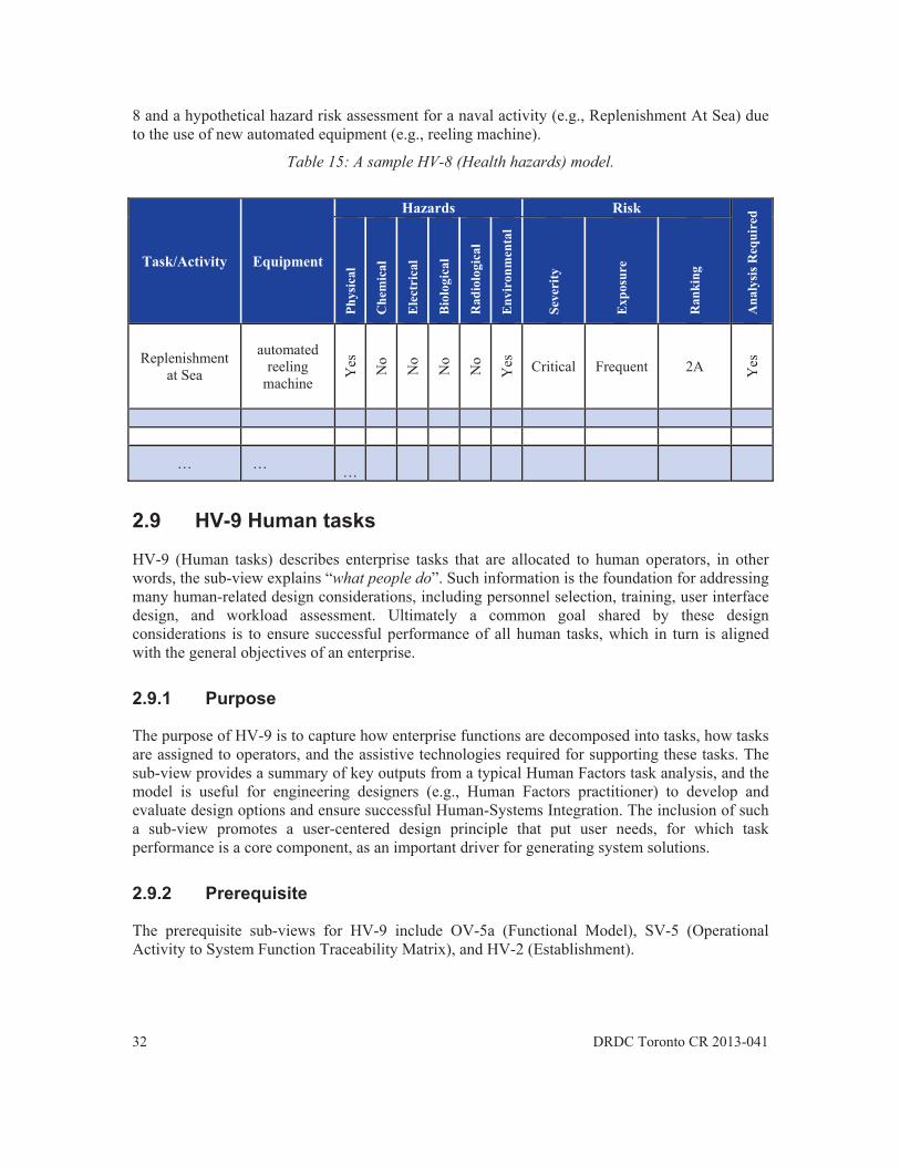
32 DRDC Toronto CR 2013-041
8 and a hypothetical hazard risk assessment for a naval activity (e.g., Replenishment At Sea) due to the use of new automated equipment (e.g., reeling machine).
Table 15: A sample HV-8 (Health hazards) model.
2.9 HV-9 Human tasks
HV-9 (Human tasks) describes enterprise tasks that are allocated to human operators, in other words, the sub-view explains “what people do”. Such information is the foundation for addressing many human-related design considerations, including personnel selection, training, user interface design, and workload assessment. Ultimately a common goal shared by these design considerations is to ensure successful performance of all human tasks, which in turn is aligned with the general objectives of an enterprise.
2.9.1 Purpose
The purpose of HV-9 is to capture how enterprise functions are decomposed into tasks, how tasks are assigned to operators, and the assistive technologies required for supporting these tasks. The sub-view provides a summary of key outputs from a typical Human Factors task analysis, and the model is useful for engineering designers (e.g., Human Factors practitioner) to develop and evaluate design options and ensure successful Human-Systems Integration. The inclusion of such a sub-view promotes a user-centered design principle that put user needs, for which task performance is a core component, as an important driver for generating system solutions.
2.9.2 Prerequisite
The prerequisite sub-views for HV-9 include OV-5a (Functional Model), SV-5 (Operational Activity to System Function Traceability Matrix), and HV-2 (Establishment).
Task/Activity Equipment
Hazards Risk
Ana
lysi
s Req
uire
d
Phys
ical
Che
mic
al
Ele
ctri
cal
Bio
logi
cal
Rad
iolo
gica
l
Env
iron
men
tal
Seve
rity
Exp
osur
e
Ran
king
Replenishment at Sea
automated reeling
machine
Yes
No
No
No
No
Yes
Critical Frequent 2A Yes
… … …
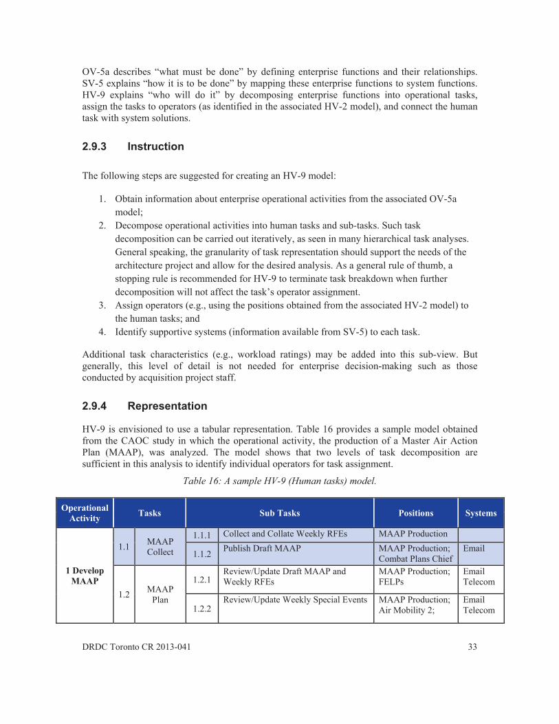
DRDC Toronto CR 2013-041 33
OV-5a describes “what must be done” by defining enterprise functions and their relationships. SV-5 explains “how it is to be done” by mapping these enterprise functions to system functions. HV-9 explains “who will do it” by decomposing enterprise functions into operational tasks, assign the tasks to operators (as identified in the associated HV-2 model), and connect the human task with system solutions.
2.9.3 Instruction The following steps are suggested for creating an HV-9 model:
1. Obtain information about enterprise operational activities from the associated OV-5a model;
2. Decompose operational activities into human tasks and sub-tasks. Such task decomposition can be carried out iteratively, as seen in many hierarchical task analyses. General speaking, the granularity of task representation should support the needs of the architecture project and allow for the desired analysis. As a general rule of thumb, a stopping rule is recommended for HV-9 to terminate task breakdown when further decomposition will not affect the task’s operator assignment.
3. Assign operators (e.g., using the positions obtained from the associated HV-2 model) to the human tasks; and
4. Identify supportive systems (information available from SV-5) to each task.
Additional task characteristics (e.g., workload ratings) may be added into this sub-view. But generally, this level of detail is not needed for enterprise decision-making such as those conducted by acquisition project staff.
2.9.4 Representation
HV-9 is envisioned to use a tabular representation. Table 16 provides a sample model obtained from the CAOC study in which the operational activity, the production of a Master Air Action Plan (MAAP), was analyzed. The model shows that two levels of task decomposition are sufficient in this analysis to identify individual operators for task assignment.
Table 16: A sample HV-9 (Human tasks) model.
Operational Activity Tasks Sub Tasks Positions Systems
1 Develop MAAP
1.1 MAAP Collect
1.1.1 Collect and Collate Weekly RFEs MAAP Production
1.1.2 Publish Draft MAAP MAAP Production;Combat Plans Chief
1.2 MAAP Plan
1.2.1 Review/Update Draft MAAP and Weekly RFEs
MAAP Production;FELPs
Email Telecom
1.2.2 Review/Update Weekly Special Events MAAP Production;
Air Mobility 2; Email Telecom

34 DRDC Toronto CR 2013-041
Operational Activity Tasks Sub Tasks Positions Systems
Air Mobility 3
1.2.3 Review Mission Support Requirements MAAP; TIS; CE;
Air Maintenance; Logistics
Email Telecom
1.2.4 Prepare Recommended MAAP MAAP Production NAPPIC
1.2.5 Prepare Mission Support Brief and Tasking Order
MAAP Production Email
1.3 MAAP Approve
1.3.1 Review / Approve Recommended MAAP and Mission Support Plan
MAAP Production;Mission Support; Director CAOC
1.3.2 Distribute MAAP MAAP Production NAPPIC 1.3.3 Distribute Mission Support Plan MAAP Production Email
1.4
MAAP Task /
Execute / Assess
Currently not supported in CAOC
2.10 HV-10 Communications
HV-10 (Communications) describes inter-operator communication requirements for supporting team functions. While HV-9 provides a comprehensive model of all human tasks, HV-10 focuses on a sub-set of the human tasks, that is, the teamwork, and depicts task requirements for information exchange among operators.
The scope of HV-10 overlaps with that of OV-3 (Operational Information Exchange Matrix) and SV-2 (Systems Communications Description). However, there are significant differences between these sub-views.
HV-10 is specifically designed to capture inter-personnel communication requirements at the individual level, whereas SV-2 describes connectivity links among organizational nodes and emphasizes the hardware and software infrastructure that facilitates the exchange of information among the organizational nodes. Like the rest of the SVs, SV-2 provides an architectural model of the system solutions. In contrast, HV-10 focuses on operational requirements and describes why a communication link is needed by identifying the human task that demands it.
The differences between HV-10 and OV-3 are more subtle. Both are intended to provide traceable evidences to justify the needed for information exchange among operators. The utility of an OV-3 model is to identify, develop, or evaluate communication systems and infrastructures. For HV-10, its purpose is to support collaborative work and enhance teamwork performance. As a result, the attributes suggested in OV-3 mainly focus on those factors external to an individual whereas HV-10 attempts to capture the human characteristics such as the sensory channel through which information is transmitted.

DRDC Toronto CR 2013-041 35
2.10.1 Purpose
The purpose of HV-10 is to capture the existing or projected human to human communication patterns within collocated or distributed teams. The sub-view facilitates a better understanding of inter-personnel communication, which is needed in the following types of activities:
Transmitting data; Sharing (access to) information; Retrieving or accessing data and information; Conversations and dialogues; Shared coordination activities; and Mutual/shared awareness-building.
An HV-10 model describes the intent of information flow and the sensory channels required for information transmission. It supports the analysis of many HF issues including collaborative work design, teamwork effectiveness, and workspace room layout.
2.10.2 Prerequisite
The HV-9 (Human tasks) is a prerequisite for this sub-view. The development of an HV-10 model starts with an identification of team tasks in the corresponding HV-9 model.
OV-2 (Operational Node Connectivity Description), OV-3 (Operational Information Exchange Matrix), and SV-2 (Systems Communications Description) are optional sub-views that assist the construction of an HV-10 model. Together these sub views provide a comprehensive model of the communication network by describing both its technological and human characteristics.
2.10.3 Instruction
Table 17 provides an overview of key data elements recommended for HV-10. Berlo’s model was used as the underlying framework for describing the human characteristics in inter-operator communications [13].
Table 17: Key data elements for HV-10 (Communications)
Data element Description Operational Activity
The operational activity that generates teamwork requirements. The information is available from the associated OV-5a or HV-9 models.
Task The teamwork tasks required to support operational activities. The information is available in the associated HV-9 model.
Sub-task (Optional) decomposition of the teamwork task. The information is available in the associated HV-9 model.
Originator The communication originator, i.e., the person who has a message to be transmitted. Receiver The communication receiver, i.e., the person on the receiving end of the transmission. Channel The human sensory channel required for processing the transmitted message. Criticality How important is the communication, reflecting the severity of communication failure.
A categorical response (e.g., Low, Medium, High) is suggested which can be further

36 DRDC Toronto CR 2013-041
defined by the architect. Frequency How often information exchange takes place. Generally speaking, frequency is context
dependant and therefore is relative to the project being defined by the architecture. Sample categories for frequency are: Seldom, Occasional, Often, Frequent, and Very Frequent.
Synchronicity Whether successful information exchange requires the presence of both originator and receiver when transmission occurs.
Feedback Whether explicit acknowledgements are needed to confirm the successful receiving of the message.
Co-location requirement
Whether the originator and receiver need to be co-located based on characteristics of their communication requirements. Two operators are considered co-located when they are in a close proximity and assistive technologies are not needed to facilitate their communication.
A dual (tabular and/or graphical) representation is proposed for HV-10. The tabular representation reflects a comprehensive model of the communication requirements. Using a data table, the full list of attributes (e.g., as specified in Table 17) can be adopted for describing each communication link. An accompanying graphical representation can also be created to enhance the visualization of the communication requirements. A common format is a network diagram in which circular nodes and connecting lines are used to depict operators and communication links respectively. The connecting line can be graphically coded to represent different communication attributes. Two forms of the graphical representation are supported: an individual-centric depiction that shows the communication needs for each individual across all his/her tasks, and an activity-centric depiction that shows the team members involved in an operational activity and the required information exchanges among them.
The following steps are suggested for creating an HV-10 model:
1. From the associated HV-9 (Human tasks) model, identify team tasks that require exchanges of information among operators;
2. For each team task, specify the communication link by identifying the communication originator and receiver;
3. Determine the relevant communication attributes based on the architecture project’s needs, and specify the attributes for each communication link.
4. If needed, generate a graphical depiction of the communication patterns to facilitate better visualization.
2.10.4 Representation Table 18 provides a sample tabular representation of an HV-10 model, and the corresponding graphical representation is available in Figure 10. In this example, the models describe communication requirements for the production of the Total Air Resource Management (TARM) in the national CAOC.

DRDC
Figu
C Toronto CR 2
ure 10: A samp
2013-041
ple graphicall HV-10 (Compr
mmunications)roduction)
s) model for CCAOC analysi
3
is (i.e., TARM
37
M

38
DR
DC
Tor
onto
CR
201
3-04
1
Tabl
e 18
: A sa
mpl
e ta
bula
r HV-
10 (C
omm
unic
atio
ns) m
odel
for C
AOC
ana
lysi
s (i.e
., TA
RM p
rodu
ctio
n)
Ope
ratio
nal
Act
ivity
T
asks
Su
b T
asks
O
rigi
nato
r R
ecei
ver
Cri
tical
ity
Freq
uenc
y Sy
nchr
onic
ity
Feed
-ba
ck
Cha
nnel
1
Dev
elop
TA
RM
1.1
TAR
M
Col
lect
1.1.
1 Is
sue
Cal
l Let
ter
CA
F Su
ppor
ted
Com
man
ders
M
ediu
m
Occ
asio
nal
Asy
nchr
onou
s Y
es
Vis
ual
1.1.
2 Fo
rwar
d to
AC
CEs
Su
ppor
ted
Com
man
ders
A
CC
Es
Crit
ical
O
ccas
iona
l A
sync
hron
ous
Yes
V
isua
l
1.1.
3 C
olle
ct a
nd C
olla
te Y
early
R
FEs
Win
gs
AC
CEs
M
ediu
m
Occ
asio
nal
Asy
nchr
onou
s N
o V
isua
l
1.1.
4 C
olla
te F
orce
Gen
erat
ion
RFE
s W
ings
Fo
rce
Gen
erat
ion
Med
ium
O
ccas
iona
l A
sync
hron
ous
No
Vis
ual
1.1.
5 C
olle
ct a
nd C
olla
te Y
early
Air
Mob
ility
RFE
s W
ings
A
ir M
obili
ty 2
A
ir M
obili
ty 3
A
ir M
obili
ty 4
M
ediu
m
Occ
asio
nal
Asy
nchr
onou
s N
o V
isua
l
1.1.
6 C
olle
ct a
nd C
olla
te Y
early
Sp
ecia
l Eve
nts R
FEs
Win
gs
Spec
ial E
vent
Coo
rd
Med
ium
O
ccas
iona
l A
sync
hron
ous
No
Vis
ual
1.1.
7 C
olle
ct a
nd C
olla
te Y
early
FE
and
FG R
FEs
AC
CEs
Fo
rce
Gen
erat
ion
Air
Mob
ility
2
Air
Mob
ility
3
Air
Mob
ility
4
Spec
ial E
vent
Coo
rd
A5
/ A7
FELP
S M
ediu
m
Occ
asio
nal
Asy
nchr
onou
s N
o V
isua
l
1.1.
8 C
olle
ct a
nd C
olla
te Y
early
U
ncon
stra
ined
Dem
ands
A
5 / A
7 C
hief
Stra
t Pla
n C
ritic
al
Occ
asio
nal
Sync
hron
ous
Yes
V
isua
l an
d A
udito
ry
1.2
TAR
M P
lan
1.2.
1 A
sses
s Air
Mob
ility
C
onst
rain
ts
Air
Mob
ility
2
Air
Mob
ility
3
Air
Mob
ility
4
Chi
ef A
ir M
obilt
y A
ir M
obili
ty 2
A
ir M
obili
ty 3
A
ir M
obili
ty 4
Med
ium
O
ccas
iona
l Sy
nchr
onou
s Y
es
Vis
ual
and
Aud
itory
Chi
ef A
ir M
obili
ty
Dire
ctor
CA
OC
M
ediu
m
Occ
asio
nal
Sync
hron
ous
Yes
V
isua
l an
d A
udito
ry
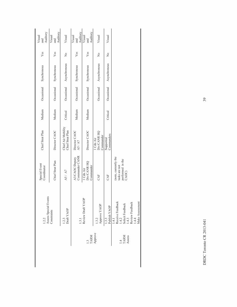
DR
DC
Tor
onto
CR
201
3-04
1 39
1.2.
2 A
sses
s Spe
cial
Eve
nts
Con
stra
ints
Spec
ial E
vent
C
oord
inat
or
Chi
ef S
trat P
lan
Med
ium
O
ccas
iona
l Sy
nchr
onou
s Y
es
Vis
ual
and
Aud
itory
Chi
ef S
trat P
lan
D
irect
or C
AO
C
Med
ium
O
ccas
iona
l Sy
nchr
onou
s Y
es
Vis
ual
and
Aud
itory
1.2.
3 D
raft
YA
OP
A5
/ A
7 C
hief
Air
Mob
ility
C
hief
Stra
t Pla
n C
ritic
al
Occ
asio
nal
Asy
nchr
onou
s N
o V
isua
l
1.3
TAR
M
App
rove
1.3.
1 R
evie
w D
raft
YA
OP
A3/
CA
OC
/Dep
uty
Com
man
der C
AN
R
Dire
ctor
CA
OC
A
5 / A
7 M
ediu
m
Occ
asio
nal
Sync
hron
ous
Yes
V
isua
l an
d A
udito
ry
1 C
dn A
ir D
iv/C
AN
R H
Q
Com
man
der
Dire
ctor
CA
OC
M
ediu
m
Occ
asio
nal
Sync
hron
ous
Yes
V
isua
l an
d A
udito
ry
1.3.
2 A
ppro
ve Y
AO
P C
AF
1 C
dn A
ir D
iv/C
AN
R H
Q
Com
man
der
O
ccas
iona
l A
sync
hron
ous
No
Vis
ual
1.3.
3 Pu
blis
h Y
AO
P C
AF
Supp
orte
d C
omm
ande
rs
Crit
ical
O
ccas
iona
l A
sync
hron
ous
No
Vis
ual
1.4
TAR
M
Ass
ess
1.4.
1 R
ecei
ve F
eedb
ack
1.4.
2 So
licit
Feed
back
1.
4.3
Rev
iew
Fee
dbac
k 1.
4.4
Mak
e A
sses
smen
t
(not
e, c
urre
ntly
the
task
s are
not
pe
rfor
med
in
the
CA
OC
)

40 DRDC Toronto CR 2013-041
3 Further discussions
The proposed Canadian HV framework is aligned with HSI domains. The ten sub-views highlight key HSI concerns and assist their consideration in enterprise architecture models. However, given the complexity of enterprise systems and the vast scope of HSI practices, the authors are aware the proposed HV may need to be adjusted to suit each architecture project’s needs. Such customization can be achieved in two ways. Within each proposed sub-view, architectural data elements can be adjusted by the architect, by removing or adding data attributes according to the needs of the specific architecture project. Alternatively the notion of fit-for-purpose sub-views is supported that allows the architect to generate tailored architectural representations by manipulating the architectural data that are captured by the existing HV framework. Section 3.1 elaborates on this concept by providing a sample rank structure sub-view.
One key application area for enterprise architecture modeling is to support project planning in large capital acquisition effort. Section 3.2 briefly explains DND’s project management process and discusses the alignment of different HV sub-views with key decision points in the acquisition process.
3.1 Fit-For-Purpose Sub-Views
In a nutshell, a fit-for-purpose sub-view refers to a customized architectural sub-view that is created locally by architects based on a project’s needs [14]. Such a sub-view relies on architectural data that are defined in DADM but adopts a representation that differs from the standard sub-views. Technically fit-for-purpose sub-views can be created by querying existing DNDAF database based on user-defined criteria. The concept reflects a shift of trend in architecture framework development from a ‘view-centric’ to a ‘data-centric’ approach. While the view-centric approach focuses on the definition of architectural representation for each sub-view, a data-centric solution emphasizes the underlying architectural data elements and allows an architect to determine the form and format of the architectural descriptions.
To better illustrate the concept, we provide a sample fit-for-purpose sub-view (i.e., rank structure sub-view) that was developed based on HV-2 (Establishment). The sub-view describes the rank
distribution across military occupations for all personnel in an organization using a tabular format. Such information is useful in the context of ship crewing analysis. A rank structure sub-
view can be created by aggregating the relevant architectural data (e.g., rank and MOS specifications for each position) captured in the corresponding HV-2 model and then
summarizing the results in a tabular format.
Table 19 shows a sample model developed for a RCN use case study in which crewing solutions for a new naval platform were analyzed.
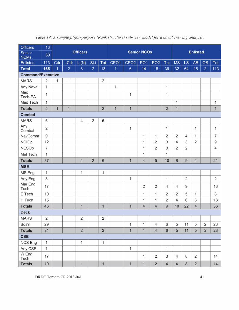
DRDC Toronto CR 2013-041 41
Table 19: A sample fit-for-purpose (Rank structure) sub-view model for a naval crewing analysis.
Officers 13 Officers Senior NCOs Enlisted Senior
NCMs 39
Enlisted 113 Cdr LCdr Lt(N) SLt Tot CPO1 CPO2 PO1 PO2 Tot MS LS AB OS Tot Total 165 1 2 8 2 13 1 6 14 18 39 32 64 15 2 113Command/Executive MARS 2 1 1 2 Any Naval 1 1 1 Med Tech-PA 1 1 1
Med Tech 1 1 1 Totals 5 1 1 2 1 1 2 1 1 Combat MARS 6 4 2 6 Any Combat 2 1 1 1 1
NavComm 9 1 1 2 2 4 1 7 NCIOp 12 1 2 3 4 3 2 9 NESOp 7 1 2 3 2 2 4 Met Tech 1 1 1 Totals 37 4 2 6 1 4 5 10 8 9 4 21 MSE MS Eng 1 1 1 Any Eng 3 1 1 2 2 Mar Eng Tech 17 2 2 4 4 9 13
E Tech 10 1 1 2 2 5 1 8 H Tech 15 1 1 2 4 6 3 13 Totals 46 1 1 1 4 4 9 10 22 4 36 Deck MARS 2 2 2 Bos'n 29 1 1 4 6 5 11 5 2 23 Totals 31 2 2 1 1 4 6 5 11 5 2 23 CSE NCS Eng 1 1 1 Any CSE 1 1 1 W Eng Tech 17 1 2 3 4 8 2 14
Totals 19 1 1 1 1 2 4 4 8 2 14

LSACRSST
42
Logistics Sea Log Any Log Cook RMS Steward Sup Tech Totals 2
3.2 Accorfacilitstrategexistin
FiPPA=
FigurephaseDirecsuppofor thmanagassoci
Tab
PADocuSS(ID
1 1 7 5 6 7 27
Applicrding to DNDtating optionsgic objectiveng assets can
Figure 11: Pro=Preliminary
e 11 was adaes, as well as tive (PAD) [
orting acquisihe architecturagement phaseiation of HV
ble 20: Recomphases (no
AD ment
D) The foresult
1 1
cation of DAF, enterprs analysis. Thes and help t
be managed
oject managemProject Appr
Capabi
apted from thethe associate17]. The mantion projects,al developmees. In this stusub-views wi
mmended assoote, the inform
Ass
following sub-vs in the Identif
1 1
the HV inrise architectuhe models ensto identify coto avoid unne
ment phases (roval; EPA=Eility; PRC=Pr
e DNDAF maed key decisionual also rec, as shown innt progress o
udy, Table 20ith project ma
ociation of DNmation regard
sociated DNDA
views will aid ification Phase:
1 1
n the Acqure models susure that acquommon needecessary proc
(note, SS(ID) Effective Projroject Comple
anual (Volumon points idenommends a m
n Table 20. Tof new archite
is extended wanagement ph
NDAF and Hding DNDAF s
AF sub-view
in presenting K
1 1 11 11 14 3
quisition Pupport DND/uisitions are a
ds so that rescurement.
= Synopsis Sject Approvaletion Report)
me 2) and illuntified in the minimum set
The recommenecture activitiwith an addithases.
HV sub-views wsub-views is a
Key Activity
DRDC Toron
1 1 1 2 2 1 2 2
3 8 4
Process /CF acquisitialigned with sources can b
Sheet (Identifil; FOC=Full .
ustrates projecDND/CF Pro
t of DNDAF ndation proviies through ditional column
with project madapted from
Associate
HV-1 (Con
nto CR 2013-04
5 3 3 3 14
ion process bthe DND/CFbe pooled an
fication); Operational
ct managemenoject Approvsub-views fo
ides a baselinifferent proje
n to indicate a
management m [11]).
d HV sub-view
ncept)
41
6 3 4 5 18
by ’s
nd
nt val or ne ct an
w

DRDC Toronto CR 2013-041 43
PAD Document Associated DNDAF sub-view Associated HV sub-view
CV-1 (Overview and summary information), OV-1 (High-level operational concept graphic), IV-1 (Strategic information model), StratV-1 (Business strategy and motivation), CapV-1 (Capability taxonomy), and SecV-1 (Risk assessment).
SS(PPA) In addition to the sub-views identified in SS(ID), the following sub-views will aid in presenting Key Activity results in the Options Analysis Phase (Note, more than one set of any sub-view may be used to define various options.) OV-1 (High-level operational concept graphic), OV-2 (Operational node connectivity description), OV-4a (Organizational relationship chart), OV-5a (Functional model), CapV-3 (Capability to operational activities mapping), SV-1 (Systems interface description), SV-5 (Operational activity to systems functions traceability matrix), SV-7 (Systems performance parameters matrix), and TV-1 (Standards profile).
HV-2 (Establishment), HV-5 (Personal characteristics), HV-6 (Training needs), HV-7 (System safety), HV-9 (Human tasks)
SS(EPA) In addition to the views identified in SS(PPA), the following sub-views will aid in presenting Key Activity results in the Definition Phase: CV-2 (Integrated data dictionary), OV-3 (Operational information exchange matrix), OV4b (Organization to role/skill matrix), OV-5b (Operational process model), OV-6a (Operational rules model), OV-6c (Operational event-trace description), SV-2 (Systems communications description), and TV-2 (Standards forecast).
HV-3 (Organization), HV-8 (Health hazards), HV-10 (Communications)
FOC In addition to final updates to the selected sub-views identified in SS(EPA), any additional sub-views developed will aid in presenting the results of the Key Activities results in the Implementation Phase.
HV-4 (Manpower projection)
PCR All the completed sub-views with a final updated CV-1will aid in presenting the Key Activity results in the Close Out Phase.
HV-4 (Manpower projection)
While Table 20 provides useful guidance on when to develop and employ DNDAF and HV sub-views in acquisition processes, it is useful to note that the scope of the architecture modeling effort differs across projects. Ultimately it is the architect’s decision to select specific sub-views and decide an implementation strategy that considers model re-use, redundancy or duplication and fits the architecture project’s needs.

44 DRDC Toronto CR 2013-041
References …..
[1] Wang, W., Coates, C., Stewart, A., Walter, D., & Au, L. Principles and approaches for developing the Canadian human view, DRDC Toronto Technical Report, TR 2013-022.
[2] Coates, C., Perlin, M., & McKay, P., Model Validation and Development for Navy Crewing Analysis, Simulation for Crew Optimization and Risk Evaluation, Contractor Report for DRDC Toronto, January 2103.
[3] Architecture Framework Analysis of RCAF CAOC, CORA Task #144, published for DRDC CORA, 10 January 2013.
[4] Wang, W. & Coates, C., Human Factors Analysis of Combined Aerospace Operations Centre (CAOC), Preliminary Results, Technical Memorandum, TM2013-109.
[5] Wang, W., & Coates, C. Human view modelling of the Virtual – Combined Aerospace Operations Centre (V-CAOC), DRDC Toronto Technical report, TR2013-078.
[6] DoDAF, Department of Defense Architecture Framework Working Group, DoD Architecture Framework Version 1.0 deskbook, Department of Defense, Washington, DC, February 2004.
[7] NATO Human View Handbook, prepared by the NATO RTO HRM-155 Human View Workshop, 2008.
[8] Human Views Extensions to the Department of Defense Architecture Framework, Kevin Baker et al, DRDC Corporate CR-2008-001.
[9] Naislin, P. “Closing Address” in “The Human as a Limiting Element in Military Systems, Proceedings of the 24th DRG Seminar”, Report DS/ A/ DR( 83) 170, Brussels: NATO DRG, 1983.
[10] Greenley, M., Scipione, A., Brooks, J., & Salwaycott, A. The Development and Validation of a Human Systems Integration (HIS) Program for the Canadian Department of National Defence (DND), DRDC CR 2008-005, September 2008.
[11] DND/CF Architecture Framework Version 1.8 Volume 2: DND/CF Views and Sub-Views 30 June 2011, Ottawa, ON.
[12] MIL-STD-882E – Department of Defense Standard Practice: System Safety.
[13] Berlo, D. K. The process of communication. New York, New York: Holt, Rinehart, & Winston (1960).
[14] Handley, H. A. H., Incorporating the NATO Human View in the DoDAF 2.0 Meta Model, 1 June 2011.

DRDC Toronto CR 2013-041 45
[15] A-GG-040-007/AG-001, General Safety Program, Volume 7, Handbook for the Safety Program Development and Evaluation Technique, D SAFE G, Department of National Defence, 1 January 2002.
[16] A-GG-040-001/AG-001, General Safety Program, Volume 1, Policy and Program, Development and Evaluation Technique, D SAFE G, Department of National Defence, 1 June 2006.
[17] DND/CF Project Approval Directive (PAD 2011-2012), Department of National Defence, 2011.
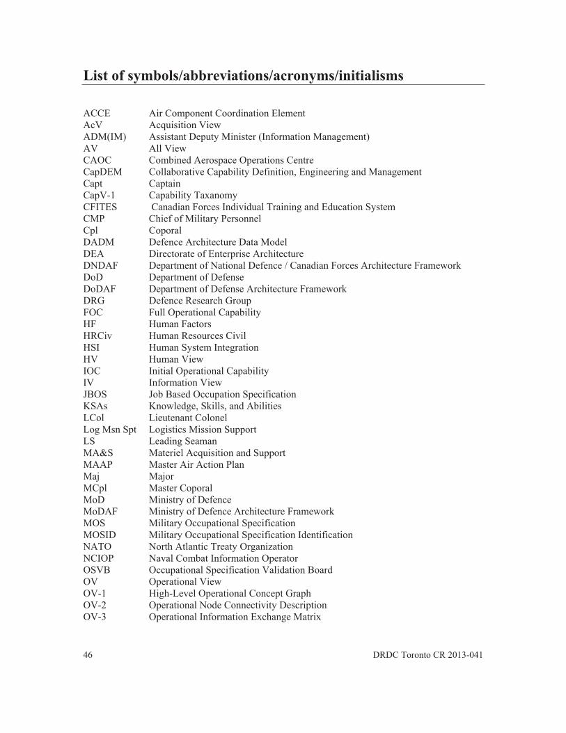
46 DRDC Toronto CR 2013-041
List of symbols/abbreviations/acronyms/initialisms
ACCE Air Component Coordination Element AcV Acquisition View ADM(IM) Assistant Deputy Minister (Information Management) AV All View CAOC Combined Aerospace Operations Centre CapDEM Collaborative Capability Definition, Engineering and Management Capt Captain CapV-1 Capability Taxanomy CFITES Canadian Forces Individual Training and Education System CMP Chief of Military Personnel Cpl Coporal DADM Defence Architecture Data Model DEA Directorate of Enterprise Architecture DNDAF Department of National Defence / Canadian Forces Architecture Framework DoD Department of Defense DoDAF Department of Defense Architecture Framework DRG Defence Research Group FOC Full Operational Capability HF Human Factors HRCiv Human Resources Civil HSI Human System Integration HV Human View IOC Initial Operational Capability IV Information View JBOS Job Based Occupation Specification KSAs Knowledge, Skills, and Abilities LCol Lieutenant Colonel Log Msn Spt Logistics Mission Support LS Leading Seaman MA&S Materiel Acquisition and Support MAAP Master Air Action Plan Maj Major MCpl Master Coporal MoD Ministry of Defence MoDAF Ministry of Defence Architecture Framework MOS Military Occupational Specification MOSID Military Occupational Specification Identification NATO North Atlantic Treaty Organization NCIOP Naval Combat Information Operator OSVB Occupational Specification Validation Board OV Operational View OV-1 High-Level Operational Concept Graph OV-2 Operational Node Connectivity Description OV-3 Operational Information Exchange Matrix

DRDC Toronto CR 2013-041 47
OV-4a Organizational Relationship Chart PO2 Petty Officer Second Class QL Qualification Level RCAF Royal Canadian Air Force RCN Royal Canadian Navy SecV Security View StV Strategic View SV System View SV-2 Systems Communications Description TAD Target Audience Description TDP Technology Demonstration Project TIS Technical Information Support TV Technical and Standards View TV-2 Standards Forecast WO Warrant Officer
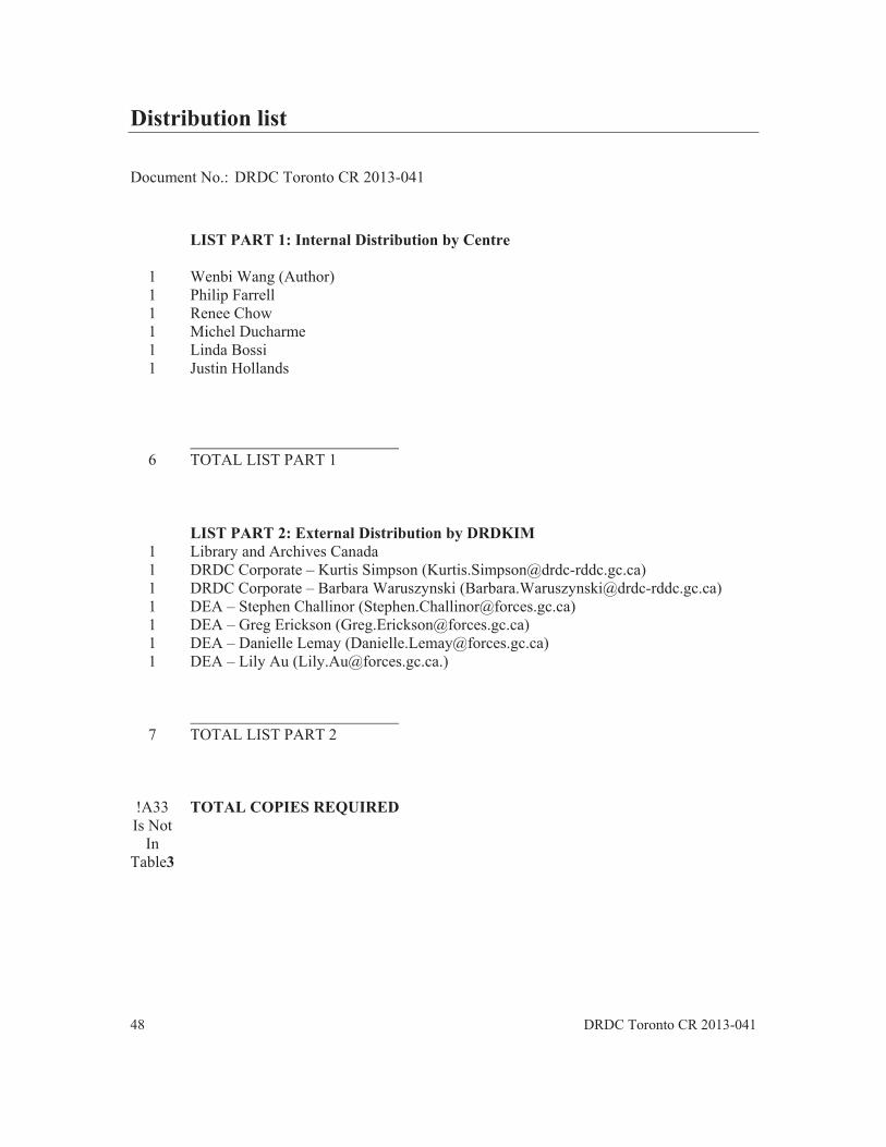
48 DRDC Toronto CR 2013-041
Distribution list
Document No.: DRDC Toronto CR 2013-041
LIST PART 1: Internal Distribution by Centre
1 Wenbi Wang (Author) 1 Philip Farrell 1 Renee Chow 1 Michel Ducharme 1 Linda Bossi 1 Justin Hollands
6 TOTAL LIST PART 1
LIST PART 2: External Distribution by DRDKIM 1 Library and Archives Canada 1 DRDC Corporate – Kurtis Simpson ([email protected]) 1 DRDC Corporate – Barbara Waruszynski ([email protected]) 1 DEA – Stephen Challinor ([email protected]) 1 DEA – Greg Erickson ([email protected]) 1 DEA – Danielle Lemay ([email protected]) 1 DEA – Lily Au ([email protected].)
7 TOTAL LIST PART 2
!A33 Is Not
In Table3
TOTAL COPIES REQUIRED

DRDC Toronto CR 2013-041 49
This page intentionally left blank.

DOCUMENT CONTROL DATA (Security classification of title, body of abstract and indexing annotation must be entered when the overall document is classified)
1. ORIGINATOR (The name and address of the organization preparing the document. Organizations for whom the document was prepared, e.g. Centre sponsoring a contractor's report, or tasking agency, are entered in section 8.) Esterline | CMC Electronics 415 Legget Drive, PO Box 13330Ottawa, ON, CANADA K2K 2B2
2. SECURITY CLASSIFICATION (Overall security classification of the document including special warning terms if applicable.)
UNCLASSIFIED (NON-CONTROLLED GOODS) DMC A REVIEW: GCEC APRIL 2011
3. TITLE (The complete document title as indicated on the title page. Its classification should be indicated by the appropriate abbreviation (S, C or U) in parentheses after the title.) Canadian Human View Handbook:
4. AUTHORS (last name, followed by initials – ranks, titles, etc. not to be used)
[Coates, C.; Stewart, A.; Wang; W.] 5. DATE OF PUBLICATION
(Month and year of publication of document.) July 2013
6a. NO. OF PAGES (Total containing information, including Annexes, Appendices, etc.)
64
6b. NO. OF REFS (Total cited in document.)
0 7. DESCRIPTIVE NOTES (The category of the document, e.g. technical report, technical note or memorandum. If appropriate, enter the type of report, e.g.
interim, progress, summary, annual or final. Give the inclusive dates when a specific reporting period is covered.) Contract Report
8. SPONSORING ACTIVITY (The name of the department project office or laboratory sponsoring the research and development – include address.) Defence R&D Canada – Toronto 1133 Sheppard Avenue West P.O. Box 2000 Toronto, Ontario M3K 2C9
9a. PROJECT OR GRANT NO. (If appropriate, the applicable research and development project or grant number under which the document was written. Please specify whether project or grant.)
9b. CONTRACT NO. (If appropriate, the applicable number under which the document was written.)
10a. ORIGINATOR'S DOCUMENT NUMBER (The official document number by which the document is identified by the originating activity. This number must be unique to this document.) 1000-1505
10b. OTHER DOCUMENT NO(s). (Any other numbers which may be assigned this document either by the originator or by the sponsor.) DRDC Toronto CR 2013-041
11. DOCUMENT AVAILABILITY (Any limitations on further dissemination of the document, other than those imposed by security classification.)
Unlimited
12. DOCUMENT ANNOUNCEMENT (Any limitation to the bibliographic announcement of this document. This will normally correspond to the Document Availability (11). However, where further distribution (beyond the audience specified in (11) is possible, a wider announcement audience may be selected.)) Unlimited

13. ABSTRACT (A brief and factual summary of the document. It may also appear elsewhere in the body of the document itself. It is highly desirable that the abstract of classified documents be unclassified. Each paragraph of the abstract shall begin with an indication of the security classification of the information in the paragraph (unless the document itself is unclassified) represented as (S), (C), (R), or (U). It is not necessary to include here abstracts in both official languages unless the text is bilingual.)
As a result of information technology and acquisition reform within Allied defence communitiesarchitectural approaches have emerged and are evolving as a structure for the development of asystems architecture or enterprise architecture. While international architecture frameworks evolve to include new concepts in System Engineering, the portrayal of the human as a uniquepart of the system has not been addressed. A Human View is required to explicitly represent thehuman and to document the unique implications humans bring to and impose on the system design. To that end, the idea of Human Views, which leverages Human System Integration principles, has emerged. The purpose of the Human View is to capture the human requirementsand to cater to and inform on how the human interacts in the system. This report defines the Human Views that are applicable to the Department of National Defence / Canadian ForcesArchitecture Framework (DNDAF).
Compte tenu de la poussée rapide de la technologie de l’information et de la réforme de l’acquisition au sein des collectivités de la défense des Alliés, l’architecture d’entreprise a fait son apparition et est devenue une démarche efficace pour appuyer la gestion de systèmes complexes et leur évolution au fil du temps. Les cadres d’architecture, comme le Cadre d’architecture du ministère de la Défense nationale et des Forces canadiennes (CA MDN), décrivent une démarche commune pour le développement, la présentation et l’intégration des descriptions architecturales. Bien que les cadres architecturaux internationaux évoluent pour inclure de nouveaux concepts en systémique, on n’a pas bien tenu compte de la représentation de l’être humain comme élément unique du système. Il faut un point de vue architectural pour représenter de façon explicite l’être humain et pour documenter les particularités que l’être humain apporte et impose à la conception du système d’entreprise. À cette fin, le concept de perspective humaine (PH), qui tire parti des principes et des pratiques de l’intégration des systèmes humaines (ISH), a fait surface.
La raison d’être de la PH est de saisir les caractéristiques des être humains, leurs exigences professionnelles, ainsi que de guider leur façon d’interagir avec les systèmes technologiques àl’appui des objectifs de l’entreprise. Le présent document définit un ensemble de PH qui a été élaboré afin d’améliorer le CA MDN, en mettant surtout l’accent sur le soutien aux projets d’acquisition du MDN.
14. KEYWORDS, DESCRIPTORS or IDENTIFIERS (Technically meaningful terms or short phrases that characterize a document and could be helpful in cataloguing the document. They should be selected so that no security classification is required. Identifiers, such as equipment model designation, trade name, military project code name, geographic location may also be included. If possible keywords should be selected from a published thesaurus, e.g. Thesaurus of Engineering and Scientific Terms (TEST) and that thesaurus identified. If it is not possible to select indexing terms which are Unclassified, the classification of each should be indicated as with the title.)
Human Systems Integration; modelling and simulation; manning; crewing; acquisition; enterprise architecture; DNDAF