CAN Peripheral Module - Texas...
22
CAN Peripheral Module Introduction This module covers the CAN peripheral, library and examples provided with the LM3S8962 evaluation kit. Learning Objectives • CAN Basics • Ethernet vs. CAN • CAN Drivers • CAN Stacks • Lab Stellaris One-Day Workshop - CAN Peripheral 12 - 1
Transcript of CAN Peripheral Module - Texas...
CAN Peripheral Module
Introduction This module covers the CAN peripheral, library and examples provided with the LM3S8962 evaluation kit.
Learning Objectives • CAN Basics
• Ethernet vs. CAN
• CAN Drivers
• CAN Stacks
• Lab
Stellaris One-Day Workshop - CAN Peripheral 12 - 1
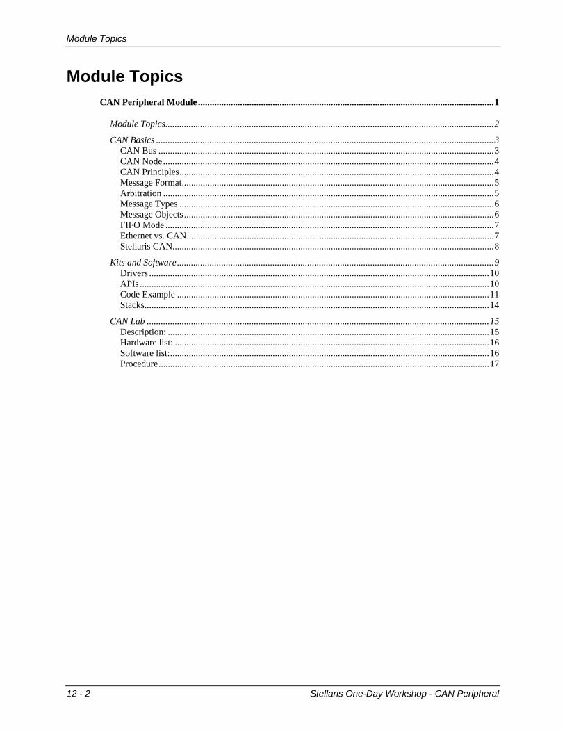
Module Topics
Module Topics CAN Peripheral Module ...............................................................................................................................1
Module Topics.............................................................................................................................................2 CAN Basics .................................................................................................................................................3
CAN Bus ................................................................................................................................................3 CAN Node..............................................................................................................................................4 CAN Principles.......................................................................................................................................4 Message Format......................................................................................................................................5 Arbitration ..............................................................................................................................................5 Message Types .......................................................................................................................................6 Message Objects .....................................................................................................................................6 FIFO Mode .............................................................................................................................................7 Ethernet vs. CAN....................................................................................................................................7 Stellaris CAN..........................................................................................................................................8
Kits and Software........................................................................................................................................9 Drivers ..................................................................................................................................................10 APIs ......................................................................................................................................................10 Code Example ......................................................................................................................................11 Stacks....................................................................................................................................................14
CAN Lab ...................................................................................................................................................15 Description: ..........................................................................................................................................15 Hardware list: .......................................................................................................................................16 Software list:.........................................................................................................................................16 Procedure..............................................................................................................................................17
12 - 2 Stellaris One-Day Workshop - CAN Peripheral
CAN Basics
CAN Basics
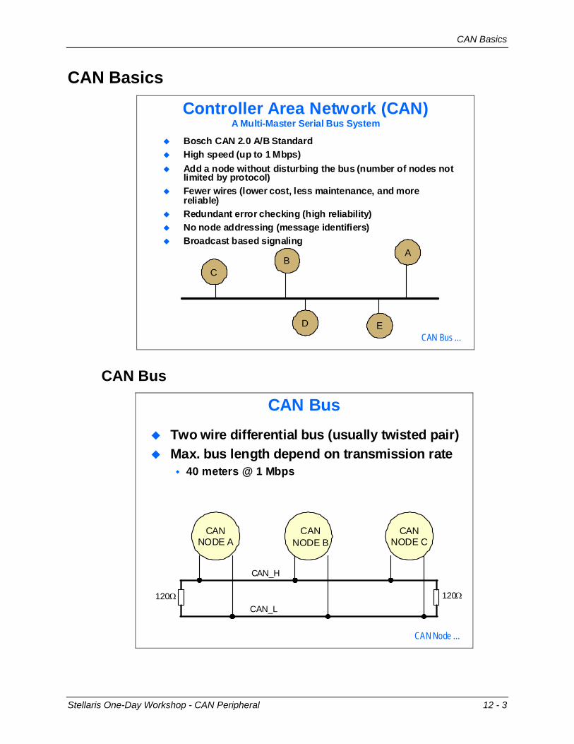
Controller Area Network (CAN)A Multi-Master Serial Bus System
Bosch CAN 2.0 A/B StandardHigh speed (up to 1 Mbps)Add a node without disturbing the bus (number of nodes not limited by protocol)Fewer wires (lower cost, less maintenance, and more reliable)Redundant error checking (high reliability)No node addressing (message identifiers)Broadcast based signaling
C
ED
AB
CAN Bus …
CAN Bus
CAN Bus
CANNODE B
CANNODE A
CANNODE C
CAN_H
CAN_L
Two wire differential bus (usually twisted pair)Max. bus length depend on transmission rate
40 meters @ 1 Mbps
120Ω120Ω
CAN Node …
Stellaris One-Day Workshop - CAN Peripheral 12 - 3
CAN Basics
CAN Node
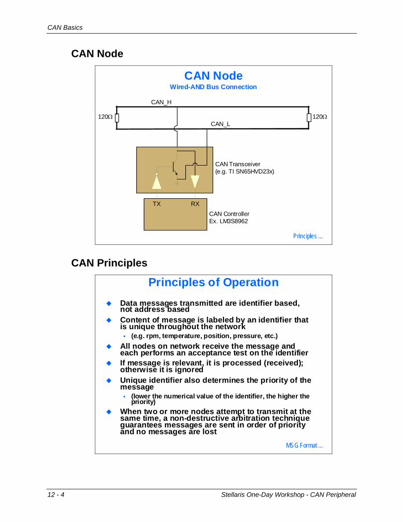
CAN NodeWired-AND Bus Connection
RXTXCAN ControllerEx. LM3S8962
CAN Transceiver(e.g. TI SN65HVD23x)
CAN_L
CAN_H
120Ω120Ω
Principles …
CAN Principles
Principles of OperationData messages transmitted are identifier based, not address basedContent of message is labeled by an identifier that is unique throughout the network
(e.g. rpm, temperature, position, pressure, etc.)All nodes on network receive the message and each performs an acceptance test on the identifierIf message is relevant, it is processed (received); otherwise it is ignoredUnique identifier also determines the priority of the message
(lower the numerical value of the identifier, the higher the priority)
When two or more nodes attempt to transmit at the same time, a non-destructive arbitration technique guarantees messages are sent in order of priority and no messages are lost
MSG Format …
12 - 4 Stellaris One-Day Workshop - CAN Peripheral
CAN Basics
Message Format
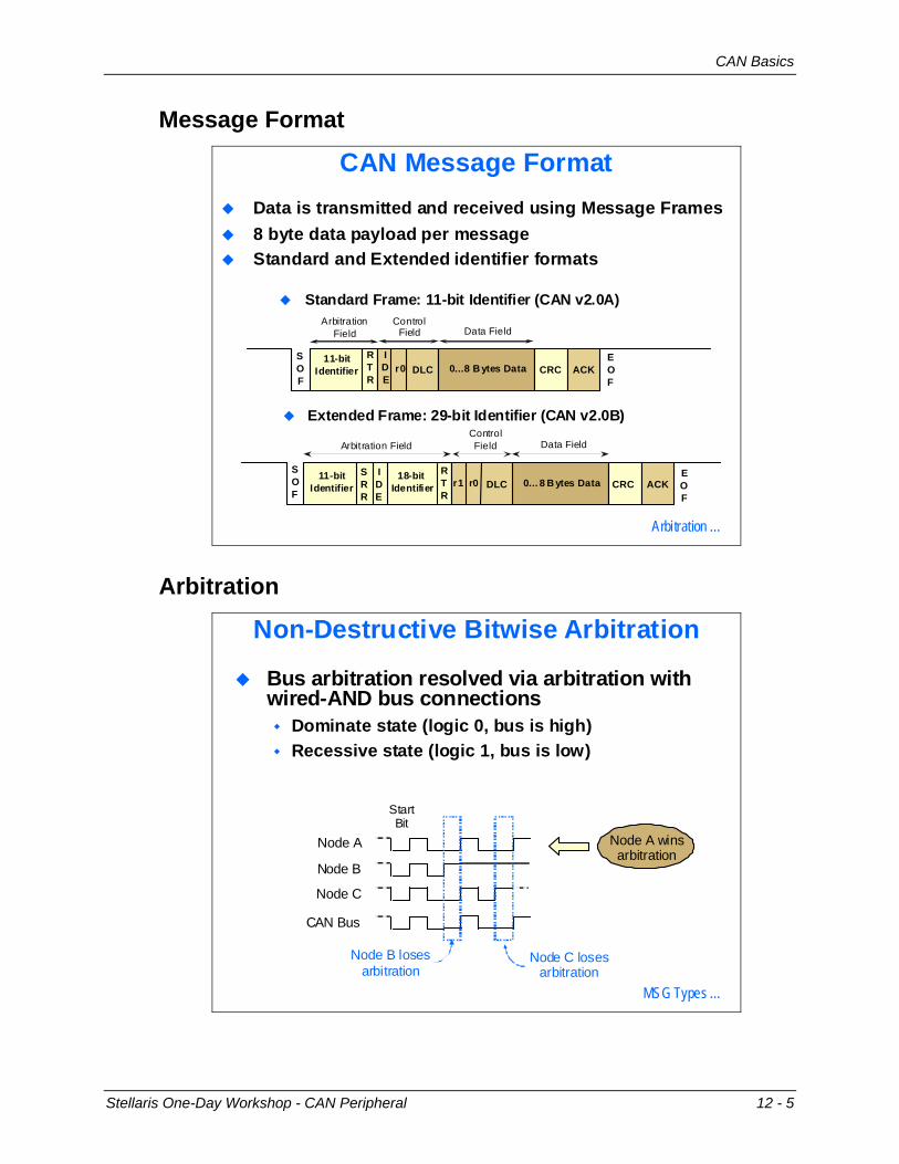
CAN Message FormatData is transmitted and received using Message Frames8 byte data payload per messageStandard and Extended identifier formats
Standard Frame: 11-bit Identifier (CAN v2.0A)
Extended Frame: 29-bit Identifier (CAN v2.0B)
11-bitIdentifier
RTR
SOF
IDE
r0 DLC 0…8 B ytes Data CRC ACKEOF
ArbitrationField
ControlField Data Field
ControlField
11-bitIdentifier
RTR
SOF
IDE
r0 DLC 0…8 B ytes Data CRC ACKr118-bit
IdentifierSRR
EOF
Arbitration Field Data Field
Arbitration …
Arbitration
Non-Destructive Bitwise Arbitration
Bus arbitration resolved via arbitration with wired-AND bus connections
Dominate state (logic 0, bus is high)Recessive state (logic 1, bus is low)
Node A wins arbitration
CAN Bus
Node A
Node B
Node C
StartBit
Node B loses arbitration
Node C loses arbitration
MSG Types …
Stellaris One-Day Workshop - CAN Peripheral 12 - 5
CAN Basics
Message Types
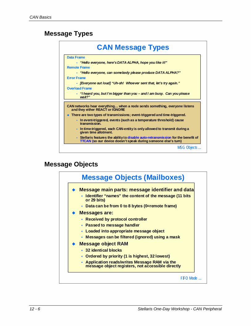
CAN Message TypesData Frame
“Hello everyone, here’s DATA ALPHA, hope you like it!”Remote Frame
“Hello everyone, can somebody please produce DATA ALPHA?”Error Frame
[Everyone out loud] “Uh-oh! Whoever sent that, let’s try again.”Overload Frame
“I heard you, but I’m bigger than you – and I am busy. Can you please wait?”
CAN networks hear everything… when a node sends something, everyone listens and they either REACT or IGNOREThere are two types of transmissions; event-triggered and time-triggered.
In event-triggered, events (such as a temperature threshold) cause transmission.In time-triggered, each CAN-entity is only allowed to transmit during a given time allotment.Stellaris features the ability to disable auto-retransmission for the benefit of TTCAN (so our device doesn’t speak during someone else’s turn)
MSG Objects …
Message Objects
Message Objects (Mailboxes)Message main parts: message identifier and data
Identifier “names” the content of the message (11 bits or 29 bits)Data can be from 0 to 8 bytes (0=remote frame)
Messages are:Received by protocol controllerPassed to message handlerLoaded into appropriate message objectMessages can be filtered (ignored) using a mask
Message object RAM32 identical blocksOrdered by priority (1 is highest, 32 lowest)Application reads/writes Message RAM via the message object registers, not accessible directly
FIFO Mode …
12 - 6 Stellaris One-Day Workshop - CAN Peripheral
CAN Basics
FIFO Mode
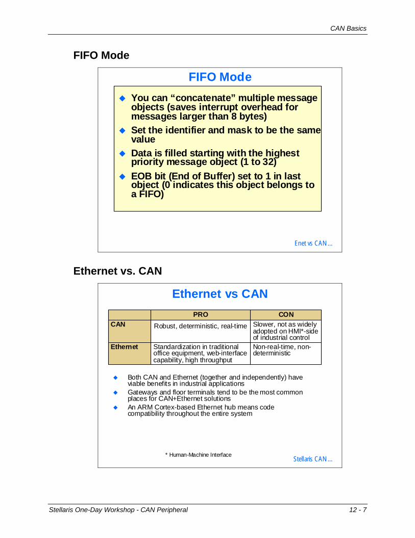
FIFO ModeYou can “concatenate” multiple message objects (saves interrupt overhead for messages larger than 8 bytes)Set the identifier and mask to be the same valueData is filled starting with the highest priority message object (1 to 32)EOB bit (End of Buffer) set to 1 in last object (0 indicates this object belongs to a FIFO)
Enet vs CAN …
Ethernet vs. CAN
Ethernet vs CAN
Both CAN and Ethernet (together and independently) have viable benefits in industrial applicationsGateways and floor terminals tend to be the most common places for CAN+Ethernet solutionsAn ARM Cortex-based Ethernet hub means code compatibility throughout the entire system
Non-real-time, non-deterministic
Standardization in traditional office equipment, web-interface capability, high throughput
Ethernet
Slower, not as widely adopted on HMI*-side of industrial control
Robust, deterministic, real-timeCANCONPRO
* Human-Machine Interface Stellaris CAN …
Stellaris One-Day Workshop - CAN Peripheral 12 - 7
CAN Basics
Stellaris CAN
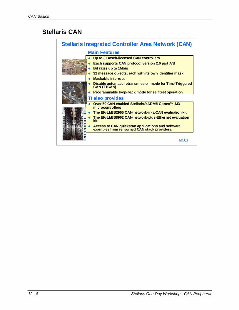
Stellaris Integrated Controller Area Network (CAN)Main Features
Up to 3 Bosch-licensed CAN controllers Each supports CAN protocol version 2.0 part A/BBit rates up to 1Mb/s32 message objects, each with its own identifier maskMaskable interruptDisable automatic retransmission mode for Time Triggered CAN (TTCAN)Programmable loop-back mode for self test operation
TI also providesOver 50 CAN-enabled Stellaris® ARM® Cortex™-M3 microcontrollers The EK-LM3S2965 CAN-network-in-a-CAN evaluation kitThe EK-LM3S8962 CAN-network-plus-Ethernet evaluation kitAccess to CAN quickstart applications and software examples from renowned CAN stack providers.
MCUs …
12 - 8 Stellaris One-Day Workshop - CAN Peripheral
Kits and Software
Kits and Software
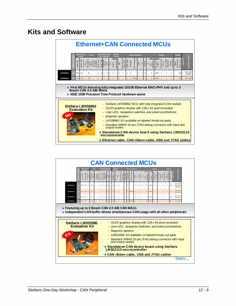
Ethernet+CAN Connected MCUs
– Stellaris LM3S8962 MCU with fully-integrated CAN module– OLED graphics display with 128 x 64 pixel resolution– User LED, navigation switches, and select pushbuttons– Magnetic speaker– LM3S8962 I/O available on labeled break-out pads– Standard ARM® 20-pin JTAG debug connector with input and
output modes
Standalone CAN device board using Stellaris LM3S2110 microcontrollerEthernet cable, CAN ribbon cable, USB and JTAG cables
Out
puts
Fault
Inpu
ts
ADC
C
hann
els
ADC
Spe
ed
(Ksp
s)
LM3S8000s 12 256 64 - 50 - 4 8 1 6 ? 6 1 2 ? ? 3 - 3 2 2 - 8 1000 ? ? 3 - 46 ?100-LQFP108-BGA
LM3S9000s 6 256 96 ? 100 ? 4 8 2 8 ? 8 4 2 ? ? 2 O/H/D 3 2 2 ? 16 1000 ? ? 3 7 65 ? 100-LQFP
LDO
Vol
tage
R
egul
ator
Ana
log
Com
para
tors
Digi
tal
Com
para
tors
GPI
Os
(5-V
)
MCU
s in
Ser
ies
UAR
T
I2 C
SSI/S
PI
I2 S
ADC (10-bit )
Inte
rnal
Tem
p Se
nsor
PWM
QEI
10/1
00 E
ther
net
MAC
+PHY
IEEE
158
8
CAN
MA
C
USB
Ful
l Spe
ed
Analog Digital
Hib
erna
te
Pack
age
Opt
ions
Flas
h (K
B)
SRA
M (K
B)R
OM
SW
Lib
rary
Max
Spe
ed
(MHz
)In
tern
al
Prec
ision
O
scilla
tor
32-b
it Ti
mer
Memory and Speed
Core General Purpose Timer Modules
Motion Control
Serial Interfaces
16-b
it Ti
mer
Wat
chdo
g Ti
mer
sCC
P
RTC
Stellaris LM3S8962 Evaluation Kit
First MCUs featuring fully integrated 10/100 Ethernet MAC+PHY and up to 3 Bosch CAN 2.0 A/B MACsIEEE 1588 Precision Time Protocol hardware assist
$89
CAN Connected MCUs
– OLED graphics display with 128 x 64 pixel resolution– User LED, navigation switches, and select pushbuttons– Magnetic speaker– LM3S2965 I/O available on labeled break-out pads– Standard ARM® 20-pin JTAG debug connector with input
and output modesStandalone CAN device board using Stellaris
LM3S2110 microcontrollerCAN ribbon cable, USB and JTAG cables
Ou
tpu
ts
Fau
lt In
put
s
AD
C
Ch
ann
els
AD
C S
pee
d
(Ksp
s)
LM 3S200 0s 2 6 25 6 96 ? 8 0 ? 4 8 2 8 ? 8 4 2 - - 2 - 3 2 2 ? 16 10 00 ? ? 3 7 60 ?64 -L QFP10 0-L QFP10 8-BG A
LM 3S500 0s 1 2 25 6 96 ? 8 0 ? 4 8 2 8 ? 8 4 2 - - 2 O/H/ D 3 2 2 ? 16 10 00 ? ? 3 7 71 ?64 -L QFP10 0-L QFP
LM 3S800 0s 1 2 25 6 64 - 5 0 - 4 8 1 6 ? 6 1 2 ? ? 3 - 3 2 2 - 8 10 00 ? ? 3 - 46 ?10 0-L QFP10 8-BG A
LM 3S900 0s 6 25 6 96 ? 10 0 ? 4 8 2 8 ? 8 4 2 ? ? 2 O/H/ D 3 2 2 ? 16 10 00 ? ? 3 7 65 ? 10 0-L QFP
LD
O V
olta
ge
Reg
ula
tor
Ana
log
Com
para
tors
Dig
ital
Com
par
ator
s
GP
IOs
(5-V
)
MC
Us
in S
erie
s
UA
RT
I2 C
SS
I/SP
I
I2 S
ADC (10 -b it)
Inte
rnal
Tem
p S
ens
or
PWM
QEI
10/
100
Eth
erne
t M
AC
+PH
Y
IEE
E 15
88
CA
N M
AC
US
B F
ull
Spe
ed
Anal og Dig it al
Hib
ern
ate
Pac
kag
e O
ptio
ns
Flas
h (K
B)
SR
AM
(KB
)R
OM
SW
Li
brar
yM
ax S
pee
d
(MH
z)In
tern
al
Prec
isio
n O
scilla
tor
32-b
it T
ime
r
M emory and Spee d
Core G eneral Purpose T imer M odules
Moti on Cont rol
Se ri al In te rf ac es
16-b
it T
ime
rW
atch
dog
T
ime
rsC
CP
RT
C
Stellaris LM3S2965 Evaluation Kit
$79
Featuring up to 3 Bosch CAN 2.0 A/B CAN MACsIndependent CAN buffer allows simultaneous CAN usage with all other peripherals
Drivers …
Stellaris One-Day Workshop - CAN Peripheral 12 - 9
Kits and Software
Drivers
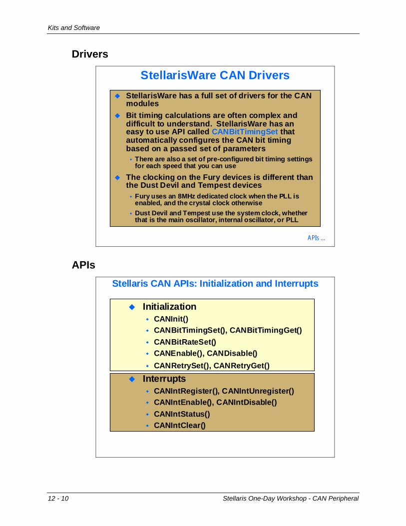
StellarisWare CAN DriversStellarisWare has a full set of drivers for the CAN modulesBit timing calculations are often complex and difficult to understand. StellarisWare has an easy to use API called CANBitTimingSet that automatically configures the CAN bit timing based on a passed set of parameters
There are also a set of pre-configured bit timing settings for each speed that you can use
The clocking on the Fury devices is different than the Dust Devil and Tempest devices
Fury uses an 8MHz dedicated clock when the PLL is enabled, and the crystal clock otherwiseDust Devil and Tempest use the system clock, whether that is the main oscillator, internal oscillator, or PLL
APIs …
APIs Stellaris CAN APIs: Initialization and Interrupts
InitializationCANInit()CANBitTimingSet(), CANBitTimingGet()CANBitRateSet()CANEnable(), CANDisable()CANRetrySet(), CANRetryGet()
InterruptsCANIntRegister(), CANIntUnregister()CANIntEnable(), CANIntDisable()CANIntStatus()CANIntClear()
12 - 10 Stellaris One-Day Workshop - CAN Peripheral
Kits and Software
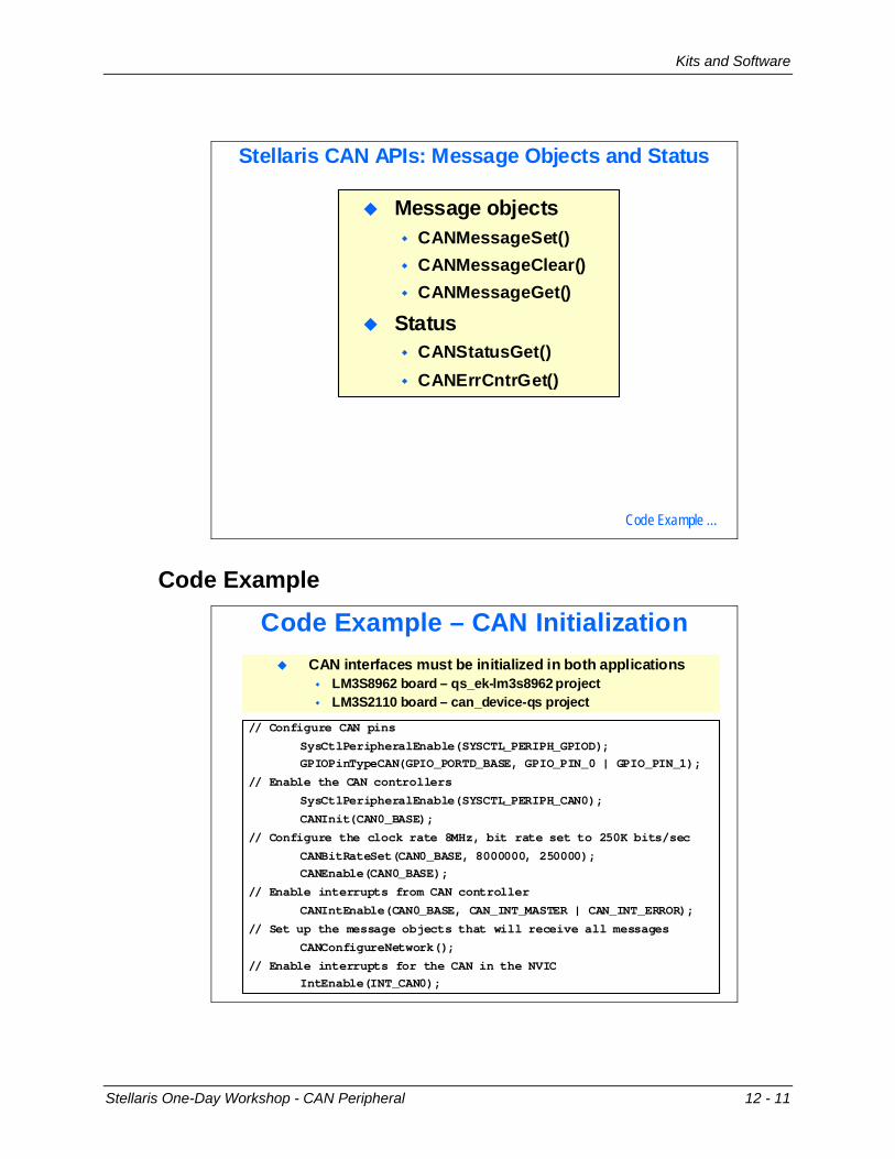
Stellaris CAN APIs: Message Objects and Status
Message objectsCANMessageSet()CANMessageClear()CANMessageGet()
StatusCANStatusGet()CANErrCntrGet()
Code Example …
Code Example
Code Example – CAN Initialization
// Configure CAN pins
SysCtlPeripheralEnable(SYSCTL_PERIPH_GPIOD);GPIOPinTypeCAN(GPIO_PORTD_BASE, GPIO_PIN_0 | GPIO_PIN_1);
// Enable the CAN controllers
SysCtlPeripheralEnable(SYSCTL_PERIPH_CAN0);
CANInit(CAN0_BASE);
// Configure the clock rate 8MHz, bit rate set to 250K bits/sec
CANBitRateSet(CAN0_BASE, 8000000, 250000);CANEnable(CAN0_BASE);
// Enable interrupts from CAN controller
CANIntEnable(CAN0_BASE, CAN_INT_MASTER | CAN_INT_ERROR);
// Set up the message objects that will receive all messages
CANConfigureNetwork();
// Enable interrupts for the CAN in the NVICIntEnable(INT_CAN0);
CAN interfaces must be initialized in both applicationsLM3S8962 board – qs_ek-lm3s8962 projectLM3S2110 board – can_device-qs project
Stellaris One-Day Workshop - CAN Peripheral 12 - 11
Kits and Software
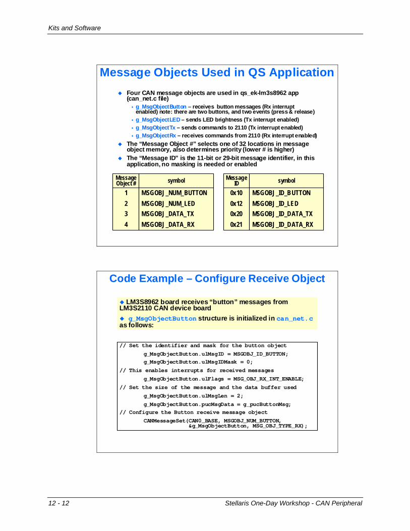
Message Objects Used in QS ApplicationFour CAN message objects are used in qs_ek-lm3s8962 app (can_net.c file)
g_MsgObjectButton – receives button messages (Rx interrupt enabled) note: there are two buttons, and two events (press & release)g_MsgObjectLED – sends LED brightness (Tx interrupt enabled)g_MsgObjectTx – sends commands to 2110 (Tx interrupt enabled)g_MsgObjectRx – receives commands from 2110 (Rx interrupt enabled)
The “Message Object #” selects one of 32 locations in message object memory, also determines priority (lower # is higher)The “Message ID” is the 11-bit or 29-bit message identifier, in this application, no masking is needed or enabled
1234
MessageObject #
MSGOBJ_NUM_BUTTONMSGOBJ_NUM_LEDMSGOBJ_DATA_TXMSGOBJ_DATA_RX
symbol
0x100x120x200x21
MessageID
MSGOBJ_ID_BUTTONMSGOBJ_ID_LEDMSGOBJ_ID_DATA_TXMSGOBJ_ID_DATA_RX
symbol
Code Example – Configure Receive Object
// Set the identifier and mask for the button object
g_MsgObjectButton.ulMsgID = MSGOBJ_ID_BUTTON;g_MsgObjectButton.ulMsgIDMask = 0;
// This enables interrupts for received messages
g_MsgObjectButton.ulFlags = MSG_OBJ_RX_INT_ENABLE;
// Set the size of the message and the data buffer used
g_MsgObjectButton.ulMsgLen = 2;
g_MsgObjectButton.pucMsgData = g_pucButtonMsg;// Configure the Button receive message object
CANMessageSet(CAN0_BASE, MSGOBJ_NUM_BUTTON, &g_MsgObjectButton, MSG_OBJ_TYPE_RX);
LM3S8962 board receives “button” messages from LM3S2110 CAN device board
g_MsgObjectButton structure is initialized in can_net.cas follows:
12 - 12 Stellaris One-Day Workshop - CAN Peripheral
Kits and Software
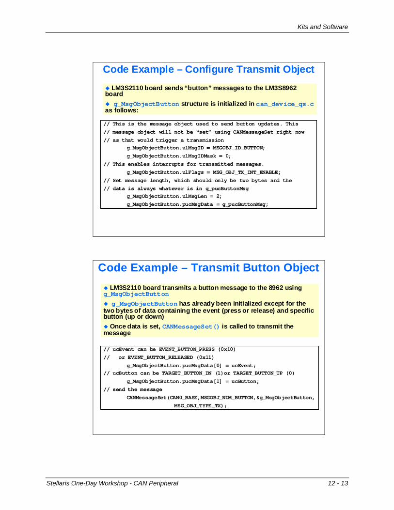
Code Example – Configure Transmit Object
// This is the message object used to send button updates. This
// message object will not be “set” using CANMessageSet right now
// as that would trigger a transmissiong_MsgObjectButton.ulMsgID = MSGOBJ_ID_BUTTON;
g_MsgObjectButton.ulMsgIDMask = 0;
// This enables interrupts for transmitted messages.
g_MsgObjectButton.ulFlags = MSG_OBJ_TX_INT_ENABLE;
// Set message length, which should only be two bytes and the
// data is always whatever is in g_pucButtonMsgg_MsgObjectButton.ulMsgLen = 2;
g_MsgObjectButton.pucMsgData = g_pucButtonMsg;
LM3S2110 board sends “button” messages to the LM3S8962 board
g_MsgObjectButton structure is initialized in can_device_qs.cas follows:
Code Example – Transmit Button Object
// ucEvent can be EVENT_BUTTON_PRESS (0x10)
// or EVENT_BUTTON_RELEASED (0x11)
g_MsgObjectButton.pucMsgData[0] = ucEvent;// ucButton can be TARGET_BUTTON_DN (1)or TARGET_BUTTON_UP (0)
g_MsgObjectButton.pucMsgData[1] = ucButton;
// send the message
CANMessageSet(CAN0_BASE,MSGOBJ_NUM_BUTTON,&g_MsgObjectButton,
MSG_OBJ_TYPE_TX);
LM3S2110 board transmits a button message to the 8962 using g_MsgObjectButton
g_MsgObjectButton has already been initialized except for the two bytes of data containing the event (press or release) and specific button (up or down)
Once data is set, CANMessageSet() is called to transmit the message
Stellaris One-Day Workshop - CAN Peripheral 12 - 13
Kits and Software
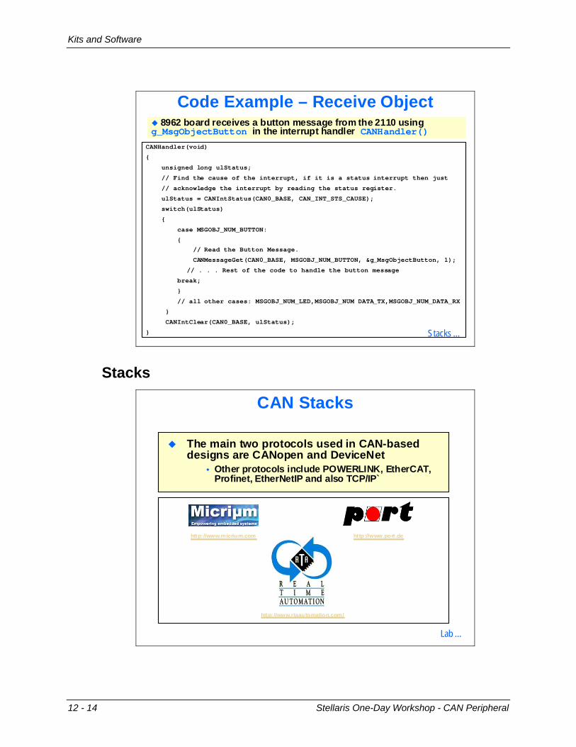
Code Example – Receive Object
CANHandler(void)
{
unsigned long ulStatus;
// Find the cause of the interrupt, if it is a status interrupt then just
// acknowledge the interrupt by reading the status register.
ulStatus = CANIntStatus(CAN0_BASE, CAN_INT_STS_CAUSE);
switch(ulStatus)
{
case MSGOBJ_NUM_BUTTON:
{
// Read the Button Message.
CANMessageGet(CAN0_BASE, MSGOBJ_NUM_BUTTON, &g_MsgObjectButton, 1);
// . . . Rest of the code to handle the button message
break;
}
// all other cases: MSGOBJ_NUM_LED,MSGOBJ_NUM DATA_TX,MSGOBJ_NUM_DATA_RX
}
CANIntClear(CAN0_BASE, ulStatus);
}
8962 board receives a button message from the 2110 using g_MsgObjectButton in the interrupt handler CANHandler()
Stacks …
Stacks
CAN Stacks
The main two protocols used in CAN-based designs are CANopen and DeviceNet
Other protocols include POWERLINK, EtherCAT, Profinet, EtherNetIP and also TCP/IP`
http://www.micrium.com
http://www.rtaautomation.com/
http://www.port.de
Lab …
12 - 14 Stellaris One-Day Workshop - CAN Peripheral
CAN Lab
CAN Lab
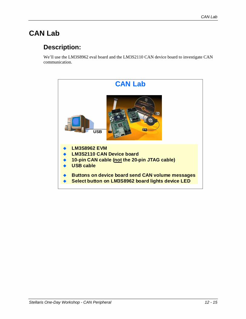
Description: We’ll use the LM3S8962 eval board and the LM3S2110 CAN device board to investigate CAN communication.
CAN Lab
LM3S8962 EVMLM3S2110 CAN Device board10-pin CAN cable (not the 20-pin JTAG cable)USB cable
Buttons on device board send CAN volume messagesSelect button on LM3S8962 board lights device LED
USB
Stellaris One-Day Workshop - CAN Peripheral 12 - 15
CAN Lab
Hardware list:
LM3S8962 Evaluation Board LM3S2110 CAN device board 10-pin CAN ribbon cable 3 meter, 4 pin, USB Type A-M to mini-USB Type B-M
Software list:
Code Composer Studio 4.1 LM3S8962 software examples
12 - 16 Stellaris One-Day Workshop - CAN Peripheral
CAN Lab
Procedure
1. Open the IDE Open Code Composer Studio and create a workspace_8962CAN workspace (we’re using a new workspace for each lab to prevent issues and learn the steps by repetition). Close the Welcome screen if it appears. Click the C/C++ Perspective button to make sure that you’re in the editing perspective.
2. Import driverlib From the menu bar, click on Project, and then select Import Existing CCS/CCE Eclipse Project. When the Import dialog appears, browse to the root directory of the driver library (C:\StellarisWare\driverlib). Click OK. Be sure that the checkbox next to driverlib in the Project pane is checked and that Copy projects into workspace is unchecked. Click Finish.
3. Import the CAN project From the menu bar, click on Project, and then select Import Existing CCS/CCE Eclipse Project. When the Import dialog appears, browse to the root directory of the quickstart project (C:\StellarisWare\boards\ek-lm3s8962\qs_ek-lm3s8962). Click OK. Be sure that the checkbox next to qs_ek-lm3s8962 in the Project pane is checked and that Copy projects into workspace is unchecked. Click Finish.
4. Open can_net.c for editing When the project has finished importing, close any open editor windows. Maximize the IDE window if you haven’t already and expand the qs_ek-lm3s8962 folder in the Projects pane.
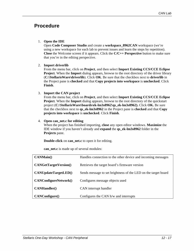
Double-click on can_net.c to open it for editing. can_net.c is made up of several modules:
CANMain() Handles connection to the other device and incoming messages
CANGetTargetVersion() Retrieves the target board’s firmware version
CANUpdateTargetLED() Sends message to set brightness of the LED on the target board
CANConfigureNetwork() Configures message objects used
CANHandler() CAN interrupt handler
CANConfigure() Configures the CAN h/w and interrupts
Stellaris One-Day Workshop - CAN Peripheral 12 - 17
CAN Lab
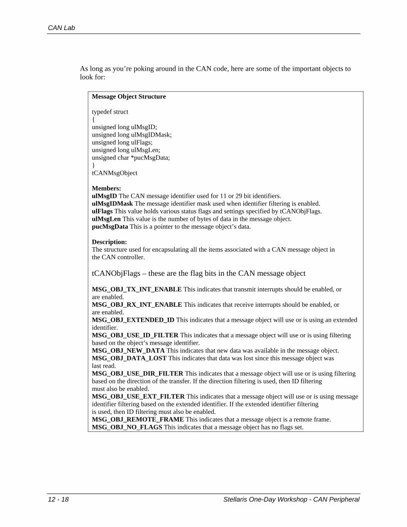
As long as you’re poking around in the CAN code, here are some of the important objects to look for:
Message Object Structure typedef struct { unsigned long ulMsgID; unsigned long ulMsgIDMask; unsigned long ulFlags; unsigned long ulMsgLen; unsigned char *pucMsgData; } tCANMsgObject Members: ulMsgID The CAN message identifier used for 11 or 29 bit identifiers. ulMsgIDMask The message identifier mask used when identifier filtering is enabled. ulFlags This value holds various status flags and settings specified by tCANObjFlags. ulMsgLen This value is the number of bytes of data in the message object. pucMsgData This is a pointer to the message object’s data. Description: The structure used for encapsulating all the items associated with a CAN message object in the CAN controller. tCANObjFlags – these are the flag bits in the CAN message object MSG_OBJ_TX_INT_ENABLE This indicates that transmit interrupts should be enabled, or are enabled. MSG_OBJ_RX_INT_ENABLE This indicates that receive interrupts should be enabled, or are enabled. MSG_OBJ_EXTENDED_ID This indicates that a message object will use or is using an extended identifier. MSG_OBJ_USE_ID_FILTER This indicates that a message object will use or is using filtering based on the object’s message identifier. MSG_OBJ_NEW_DATA This indicates that new data was available in the message object. MSG_OBJ_DATA_LOST This indicates that data was lost since this message object was last read. MSG_OBJ_USE_DIR_FILTER This indicates that a message object will use or is using filtering based on the direction of the transfer. If the direction filtering is used, then ID filtering must also be enabled. MSG_OBJ_USE_EXT_FILTER This indicates that a message object will use or is using message identifier filtering based on the extended identifier. If the extended identifier filtering is used, then ID filtering must also be enabled. MSG_OBJ_REMOTE_FRAME This indicates that a message object is a remote frame. MSG_OBJ_NO_FLAGS This indicates that a message object has no flags set.
12 - 18 Stellaris One-Day Workshop - CAN Peripheral
CAN Lab
5. Test the current software Before we change anything, let’s make sure that the project works as it is. Connect your 8962 board to your laptop. From the menu bar, click Project and then select Build Active Project. Sometimes it’s handy to build the project and check for errors without attempting to load it to Flash memory.
6. Debug and Run When the build completes, we need to load the program to the board and start the debugger. Click Target on the menu bar, then click Debug Active Project or you can
simply click the Debug button. The program will load to the 8962 Flash memory and the perspective will switch to Debug. Click the Run button to start program execution. The maze game on the OLED display should appear and the speaker should emit the game sounds.
7. Back to the Editor Click the C/C++ Perspective button (in the upper right) to return to the editor. Page down and find the CANHandler() module in can_net.c . This module handles the interrupt caused by received CAN messages. When you have more time, you can look at where those messages were sent by exploring the can_device_qs project that runs on the LM3S2110.
8. Look at CANUpdateTargetLED() We’d like to add some code that will turn the LM3S2110 board status LED on when the up button is released and off when the down button is released. If you haven’t looked closely at the CANUpdateTargetLED() module, now would be a good time to do so. Note that there are two passed parameters: ucLevel 0 is off and 1 is on bFlash true flashes the LED, false does not Calling CANUpdateTargetLED() with the correct parameters sends a CAN message from the LM3S8962 board to the LM3S2110 board.
Stellaris One-Day Workshop - CAN Peripheral 12 - 19
CAN Lab
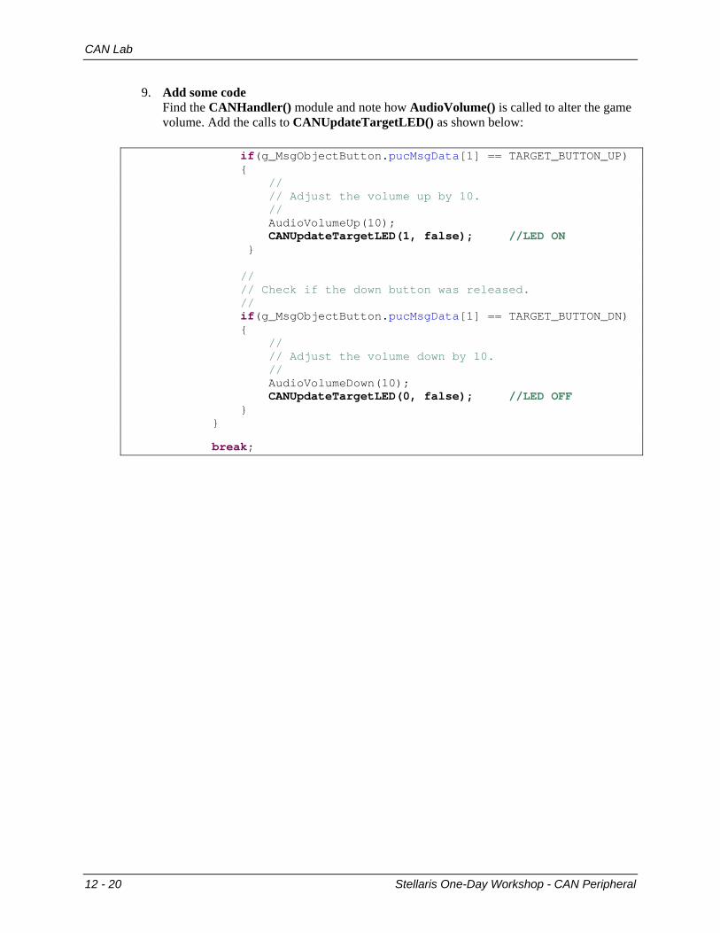
9. Add some code Find the CANHandler() module and note how AudioVolume() is called to alter the game volume. Add the calls to CANUpdateTargetLED() as shown below:
if(g_MsgObjectButton.pucMsgData[1] == TARGET_BUTTON_UP) { // // Adjust the volume up by 10. // AudioVolumeUp(10); CANUpdateTargetLED(1, false); //LED ON } // // Check if the down button was released. // if(g_MsgObjectButton.pucMsgData[1] == TARGET_BUTTON_DN) { // // Adjust the volume down by 10. // AudioVolumeDown(10); CANUpdateTargetLED(0, false); //LED OFF } }
break;
12 - 20 Stellaris One-Day Workshop - CAN Peripheral
CAN Lab
10. Change Preferences It would be nice not to have to Build and Debug in two separate steps. We can change a selection so that clicking on Debug will rebuild the project if needed. On the menu bar, click Window, then Preferences. Click on the + next to CCS, and then click on Debug. Check the Rebuild the program (if required) before loading checkbox. Click OK
11. Build/Load/Run
Click the Debug button. Save the changes to can_net.c and reload the .out file when prompted. The project will automatically build and load to the 8962 Flash memory. Change the perspective to Debug. Click the Run button to start program execution. The maze game on the OLED display should appear and the speaker should emit the game sounds.
12. Testing our changes After you click the resume button, don’t touch the up/down buttons until Press Select To Play appears on the OLED. At that point, pressing the up button on the LM3S2110 sends a VolumeUp CAN message to the LM3S8962 board, which then responds by sending a CAN message to turn on the status LED on the LM3S2110 board. The down button works in a similar fashion to turn the LED off. If you wait too long and the screen saver appears, press the Select button on the LM3S8962 board to exit the screen saver mode.
13. Remove changes Go back to the C/C++ perspective and edit the can_net.c file. Comment out the two lines that you added to the code. Build/Load/Run again to make sure you’ve removed the changes. Remember that the QuickStart application has been replaced by this application. You can reprogram it at any time with either Code Composer Studio or the Flash Programmer.
You’re done
Stellaris One-Day Workshop - CAN Peripheral 12 - 21

CAN Lab
*** A mind is the only thing that can really be blank ***
12 - 22 Stellaris One-Day Workshop - CAN Peripheral