
CAN 1 139 151 1998 GAYLORD Kitchen Ventilator With Removable Grease Extractor
16
(11) (A) No. 1 139 151 (45) ISSUED 830111 (52) CLASS 98-43 3 (51) INT. CL. F24C 15/20 (19) (CA> CANADIAN (12) (54) KITCHEN VENTILATOR WITH REMOVABLE GREASE EXTRACTOR (72) Gaylord, Edson c., u.s.A. (73) Granted to Gaylord Industries, Inc. U.S.A. (21) APPLICATION No. (22) FILED No. OF CLAIMS 366,555 801211 1 DISTRIBUTED BY THE PATENT OFFICE, OTIAWA. CCA-274 (3·80)
Transcript of CAN 1 139 151 1998 GAYLORD Kitchen Ventilator With Removable Grease Extractor

(11) (A) No. 1 139 151
(45) ISSUED 830111
(52) CLASS 98-43
3 (51) INT. CL. F24C 15/20
(19) (CA> CANADIAN PATE~NT (12)
(54) KITCHEN VENTILATOR WITH REMOVABLE GREASE EXTRACTOR
(72) Gaylord, Edson c., u.s.A.
(73) Granted to Gaylord Industries, Inc. U.S.A.
(21) APPLICATION No.
(22) FILED
No. OF CLAIMS
366,555
801211
1
DISTRIBUTED BY THE PATENT OFFICE, OTIAWA. CCA-274 (3·80)
ABSTRACT OF THE DISCLOSURE
All the grease extracting baffles arE~ incorporated
in a single unit which is removable from the ventilator for
cleaning. The baffle arrangement changes the direction of
the whole flow of air through the ventilator without divid-
ing the flow, as distinguished from removable greaae extractors
having a large number of narrow, zigzag baffles with narrow
air slots between them and mounted in a frame s~ilar to a
porous filter frame.

l139:l51
The embodiments of the invention in which an
exclusive property or privilege is claimed are
defined as follows:
1. In a kitchen ventilator having a removable
grease extractor, said ventilator having a vertical
back wall, a front. wall and a pair of opposite side
walls, a grease trough extending parallel with said
back wall, and an upstanding edge on the front side
of said trough at a d.i.stance below a lower end of
said front wall; said grease extractor comprising a
front panel having a down turned lip on its upper edge
arranged to hang on an upturned lip on said lower
end of said front wall of the ventilator, so that said
front panel forms a downward extension of said lower
end of said front wall, a pair of handles on the front
side of said front panel, the lower end of said front
panel being inclined rearward and downward substantially
into said trough behind said upstanding edge on t.he
trough to form an inlet throat opening for the ventila
tor between said trough and said front panel, a verti-
cal rear panel on said grease extractor having a down
turned lip on its lower edge supported on an upturned
lip on said back wall of the ventilator, vertical end
plates connec·ted to said front and rear panels to form
an updraft passageway between said panels for a flow of
air from said inlet throat opening, and baffle plates
projecting into said passageway from said front and
rear panels arranged to change the direction of the
whole flow of air through add passageway without divid-
ing the flow, said grease extractor with said baffle
8

1139151
plates being removable by said handles by lifting
said down turned lips on said front and rear panels
of the extractor off said upturned lips on said
front and back walls of the ventilator, said baffle
plates comprising a baffle plate projecting rearward
and downward from an upper portion of said front.
panel, and a baffle plate on said rear panel projecting
forward and down.,.Jard below said first baffle plate and
above said inclined lower end of said front panel, and
upstanding flanges on the lower edges of said baffle
plates and the lower edga of said front panel forndng
grease gutters extending along said lower edges, said
flanges terminatin9 at a short distance from said end
plates to provide drain openings at the ends of said
gutters adjacent said end plates, all the grease ex-
tracting baffles in the ventilator and all of the wall
surfaces defining said updraft passageway through said
baffles being contained in said removable grease ex-
tractor for removal as a unit for cleaning, and all of
the baffle surfaces and updraft passageway surfaces
being exposed at the opposite ends of the grease ex-
tractor when the grease extractor is removed for clean-
ing.
9
'l'his invention relates to a kitchen ventilator having
a removable grease extractor of the baffle type which abruptly
changes ·the direction of flow of a s trarnmJof contaminated air
to ex·tract grease, dust and lint particles by centrifugal
force, as distinguished from a porous filtE~r type e:s:·tractor.
It is common practice to make porous filter type
grease extractors removable for cleaning but such devices
4ave a very low effeciency in comparison with baffle type
extractors, with respect to their effectiveness in removing
10 grease and other contaminants from an air flow in a kitchen
ventilator associated with cooking equipment in a restaurant.
There are also hybrid types which have been made removable,
having a multitude of small, angular baffles which divide the
air stream in·to parallel zigzag paths for a short distance.
These baffles are mounted in shallow frames resembling filter
frames.
On the other hand it has been the practice heretofore
to provide spray nozzles in the ventilator for cleaning the
baffle plates in a baffle type grease extractor where the
20 direction of the whole flow of contaminated air is abruptly
changed repeatedly over a considerable distance for extraction
by centrifugal force. Such nozzles are supplied with hot
wa·ter and detergent to clean off the grease while the baffles
remain in their normal operative positions within the ventilator.
-1-

Such nozzles are also usually used for fire extingusbing
purposes and complicated control systems are necessary
to sched~le washing and drying cycles, including control of
the ventilating fan, and the fire extinguishing system. Means
must be provided for disposal of the spray water. Hence baffle
type grease extractors, which change the direction of the
whole flow of air over a considerable distance of travel, though
far superior to porous filter type extnactors and the hybrid
types, have become vary complicated and expensive.
10 Although baffle ·type grease extractors have been made
with some of the baffles removable, other baffles then
remain in their fixed positions in the ventilator c:md must be
cleaned in such positions by one means or another. Ji'or cleaning
purposes there is no advantage in being able to remove some
of the baffles if ·they cannot all be removed.
Thus there is a need, part.icularly in small restaurants,
for a less complicated and expensive kitchen ventilator
having a removable baffle type grease extractor which can
be cleaned by hand without requiring washing nozzles and
20 automatic washing and drying cycles controlled by ntunerous
valves and switches.
In the present construction all the grease extracting
baffles are incorporated in a unit which is bodily removable
from the ventilator. The unit rests in operative posi·tion
without any special latches, fittings or detachable connections
and is lifted out by visible and convenient handles. It is not
necessary to reach up into grease laden areas and manipulate
parts which are out of sight.
.J2-

113!}151
Thus the invention is described as a ki·tchen
ventilator having a removable grease extractor, said
ventilator having a vertical back wall, a front wall
and a pair of opposite side walla, a g:r:ease trough
ex·tending parallel with said back wall, and an up-
standing edge on the front side of said trough at a
distance below a lower end of said front wall: said
grease extractor comprising a front panel having a
down turned lip on its upper edge arranged to hang
on an upturned lip on said lower end of said frc•nt
wall of the ventilator, so that said £1.·on·t. panel fonns
a downward extension of said lower end of said front:.
wall, a pair of handles on the front. side of said front
panel, the lower end of said front panel being inclined
rearward and downward Sttbstantially into sa.td trough
behind said upstanding edge on the trough to form an
inlet throat opening for the ventilator between said
trough and said front panel, a vertical rear panel on
said grease extractor having a dovm turned lip on its
lower edge supported on an upturned lip on said back
wall of the ventilator, vertical end plates connected
to said front and rear panels to form an updraft pass-
ageway between said panels for a flow of air from said
inlet throat opening, and baffle plates projecting into
said passageway from said front and rear panels ar-
ranged to change the direction of the whole flow of
air through said passage\<Jay without dividing the flow,
said grease extractor with said baffle plates being
·,

,, J
1139151
removable by said handles by lifting said down turned
lips on said front and rear panels of the extractor
off said upturned lips on said front and back walls
of the ven·tilator, said baffle plat.es comprising a
baffle plate projecting rearward and downwal:'d from an
upper portion of said front panel, and a baffle plate
on said rear panel projecting forward and downward
below said first baffle plate and above said inclined
lower end of said front panel, and upstanding flanges
on the lower edges of said baffle plates and the lower
edge of said front panel forming grease gutters ex
tending along said lower edges, said flanges terminat
ing at a short distance .from said and plates to provide
drain openings at the ends of said gutters adjacent
said end plates, all the grease extracting baffles in
the ventilaor and all of the wall surfaces defining
said updraft passageway through said baffles being
contained in said removable grease extractor for re-
moval as a unit for cleaning, and all of the baffle
surfaces and updraft passage,-.~ay sut'faces being exposed
at the opposite ends of the grease extractor when the
grease extractor is removed for cleaning.
-3a-

The invention will be better understood and additional
objects: and advantages will become apparent from t.he following
description of the preferred embodiments illustrated in the
accompanying drawings. various changes may be made in details
of "constructions and arrangement of parts and certain features
may be used without o·thers. All such modifications within the
scope of the appended claims are included in the invention.
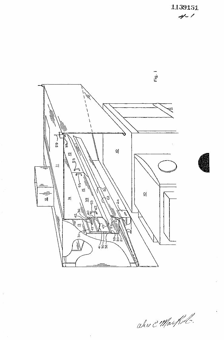
Fig. 1 is an isometric veiw with parts broken away
showing a wall type kitchen ventilator embodying the invention.
10 Fig .. 2 is exploded cross-section view of Fig. 1 showing
the grease extractor removed from the vent:llator.
Fig. 3 is an isometric view with parts broken away showing
an island ·type installation embodying the invention.
Fig. 4 is a cross-section view of the ventilator in Fig. 3.
Fig. 5 is a fragmen·tary isometric view of the adjustable
inlet throat opening in Fig. 4.
In Fig. 1 a plurality of cooking units 10 are disposed
under an overhanging hood 11. Rising above the hood 11 is a
vertical exhaust duc·t 12 containing a suction fan and normally
20 open fire damper, not shown. The exhaust duct 12 removes
contaminated hot air rising from cooking units 10 and produces
a controleed upward airflow through the grease extractor to
20
be described.
Exhaust duct 12 draws air from a horizontally elongated
chamber 13 having a front w~ll 14. The lower side of chamber
13 is open to draw air upward through one or more removable
greast extractors 15, depending upon the horizontal length of
chamber 13 which is substantially co-extensive with the cooking
units 10.
Extending downward from the bottom of chamber 13 is a
vertical back wall 20 which ·terminates in a grease ti:ough 21.
Grease trough 21 has an upper edge 22 on i·ts front side. The
grease trough slopes downward from a high end 21A (Fig. 2)
to a low and having an outlet 23 discharging into a removable
grease receptacle 24. Back wall 20 is usually adjacent a wall
of the kitchen.
As best seen in Fig. 2 the grease extractor 15 has a
vertical back panel 30 with a rearwardly and upwardly inclined
top lip 31 to bear against back wall 20 and a rearwardly and
downwardly inclined bottom lip 32 to seat on a forwardly and
upwardly inclined lip 33 on back wall 20. A vertical front
10 panel 35 has a downwardly and rearwardly i.nc lined lip 36 on its
top edge to hang on a forwardly and upwardly inclined lip 37
on the lower edge of wall 14 as a downward extension of front
wall 14. Thus the upturned lips 33 and 37 provide releasable
supporting means for the removal of grease extractor 15 for
cleaning.
Ar1 upper baffle plate 40 inclines rearwardly and downwardly
from front wall 35 and a lower baffle plate 41 inclines forwardly
and downwardly from back wall 30. Upwardly directed flanges
42 on the horizontal lower edges of these baffles form greaae
20 troughs to prevent extracted grease from d~ipping into the
air s·tream a·t random points along the horizontal length of
the baffles. Flanges 42 terminate adjacent the opposite ends
of the baffles to provide drain outlets 43 adjacent the oppos·U:~e
end plates 44 of the grease extractor 15 where descending drops
of grease are less subject. to recapture by the upward air flow
adjacent the end plates 44.
The lower portion 45 of front panel 35 of grease extractor
15 slopes rearwardly and downwardly and terminates in an up
standing flange 42 forming a grease gutter as described above.
30 This flange also terminates just short of end plates 44 to
provide drain outless 43 for the gutter out of the main air
stream.
_5_

When grease extractor 15 is inserted in operative position
the downwardly inclined panel portion 45 is spaced above the
front edge 22 of the grease trough to form an elongated inlet
throat opening 50 to admit contamina·ted air into the grease
extractor. The lower side of grease extractor 15 is open
at 51 to communicate with inlet throat opening 50 and the upper
side is open at 52 to communicate with chamber 13. Front panel
35 is equipped with two vertically elongatE~d handles 53 for
convenient removal of ·the grease ex·tractor as illustrated in
10 Fig. 2.
Thus, the grease extractor 15 is not hidden in an almost
inaccessible position within the ventilator where iss exi.s tance
may not be known to kitchen cleaning workers. ~l'he conspicous
location of handles 53 make it immediately quite obvious that
such handles must be connected ·to something re!!1ovable that would
require attention in routine kitchen maintenance.
When grease extractor 15 is removed, the grease extgacting
baffles are all cleaned as a complete unit with no other grease
extrac·ting baffles remaining in the ventilator to be cleaned
20 separately. rrhe support of grease extractor 15 on the two lips
33 and 37 makes its removal and replacement easy and convenient
without the manipulation of any fastening devices, both of
these supports being clearly visible to the operator \oJhen the
unit 15 is to be replaced. A very minimum of skill and training
are necessary for the removalp cleaning and reinsertion of the
unit.
The vertically elongated handles 53 at opposite ends of
front panel 35 p!tovide. a good grasp in the ·two hands of the
operator so that both front and rear lips 35 and 32 may be
20 lifted off their supporting lips 37 and 33 and the extractor
withdrawn in a direct straightforward movement as shown in Fig.
2 without the hands touching any greasy part of the extractor.

t·t3· ~tl··;L t';,.~ • i..J., U.l~
As shown in Fig. 2, when the grease extractor 15 is
removed for cleaning, all of the baffle surfaces and updraft
passageway surfaces are exposed at the opposite ends of
the grease extractor.
Fig. 2 also shows an opening 25 in the bottom of the
support for the removable grease receptacle 24, directly under
drain outlet pipe 23 in grease trough 21. Whenever it may be
desired to wash and flush out the trough 21, receptacle 24 is
removed and a drain hose is inserted through opening 25 and
10 connected with pipe 23.
Figs. 3-5 illustrate how the removable grease
extractors 15 may be utilized in an island type installation
having cooking units 10 and lOA on opposite sides of th•;,
ventilator at a distance from anywall. In such an installation
the ventilator and hoods 11 are supported by hangers 59 from
·the ceiling or supports above the ceiling.
The lo\'ter edge of back wall ?0 terminates at a distance
above the grease through 71 and the grease trough has a rear
upper edge 72 spaced away from back wall 70 to provide a second
:20 inlet throa·t opening 73. 'rhe width of throa·t opening 73 is
adjustable by a plate 74 secured on the lower edge of back wall 70
bu screws 75 in vertical slots 76.
Throat opening 73 may be closed by lowering pla·te 74 down
to the trough 71 or the plate may be raised ·to provide any
desired width of throat opening at 73 depending on the amount
of fumes and vapors generated by the cooking uni·ts lOA. ·rhe
cooking units lOA are generally less fume producing than the
cooking units 10 and when the cooking units lOA are not being
used the throat opening 73 is closed entirely.
_7_
\ \ \~ I \ \ \ \ \
'
---=-
l1.3~~151~
~-/
0

I 1:5
25 FIG. '2.
1139151 ~-?

1139151 ~--="

Fiu.4
3S
71
FiG. 5
ll:.J~Jl5:ll
#-~


![Pneumonia (Ventilator-associated [VAP] and non-ventilator ...](https://static.fdocuments.us/doc/165x107/61c3dfa934191a172140c0d5/pneumonia-ventilator-associated-vap-and-non-ventilator-.jpg)
