
CamVIew Tm IP Pro IP Pro-C -C IP P IP Pro
48
USER MANUAL IP PRO-C IP PRO + CAMVIEW TM IP PRO, IP PRO-C & IP PRO + P/N UM-8071 Rev. 6/2016
Transcript of CamVIew Tm IP Pro IP Pro-C -C IP P IP Pro

USER MANUAL
IP Pro-C IP Pro +CamVIew Tm IP Pro,
IP Pro-C & IP Pro +
P/N UM-8071 Rev. 6/2016

Thank you for purchasing the Triplett CamView™ Pro/Pro-C/Pro+. Please read the complete manual carefully before using the product.
To assure safe use of this product, please read the section on Safety carefully, and observe any Cautions or Warnings posted there and throughout this manual.
Please keep this manual for future reference.
SAFETY INFORMATION
• Comply with all local electrical safety and electromagnetic compatibility rules and regula-tions when using this device.
• Use original accessories with this equipment to avoid possible damage caused from unap-proved accessories.
• Accessories supplied are only intended for use with this product. Use with other products or for other purposes is not recommended.
• Do not expose the product to rain, liquids, or excessive moisture as product damage may occur.
• Do not expose or use the product in dusty or highly particulate environments.
• Avoid dropping the product or subjecting it to physical shock or high vibrations.
• Avoid leaving the product unattended while recharging it. Charging time should not exceed 8 hours. If the battery becomes hot, disconnect power immediately.
• Do not use the product in an environment containing flammable gases
• Do not attempt to disassemble the product. There are no user serviceable parts inside and product damage can occur. Contact Triplett customer service if the unit does not function properly.
• Do not use the product in environments with strong electromagnetic fields.
• Do not handle or operate the product with wet hands.
• Do not use strong detergents or solvents for cleaning the product. Wipe off dirt with a soft dry cloth, or a soft cloth slightly moistened with water or mild cleaner.

TABLE OF CONTENTS
1. Introduction. . . . . . . . . . . . . . . . . . . . . . . . . . . . . . . . . . . . . . . . . . . . . . . . . . . . . . .011.1 General Use . . . . . . . . . . . . . . . . . . . . . . . . . . . . . . . . . . . . . . . . . . . . . . . . . . . .011.2 Function Summary . . . . . . . . . . . . . . . . . . . . . . . . . . . . . . . . . . . . . . . . . . . . . . .011.3 Accessories. . . . . . . . . . . . . . . . . . . . . . . . . . . . . . . . . . . . . . . . . . . . . . . . . . . . .03
2. Device Diagram and Functions . . . . . . . . . . . . . . . . . . . . . . . . . . . . . . . . . . . . . . .042.1 Front of Tester . . . . . . . . . . . . . . . . . . . . . . . . . . . . . . . . . . . . . . . . . . . . . . . . . . .042.2 Keyboard Features . . . . . . . . . . . . . . . . . . . . . . . . . . . . . . . . . . . . . . . . . . . . . . .062.3 Back of Tester . . . . . . . . . . . . . . . . . . . . . . . . . . . . . . . . . . . . . . . . . . . . . . . . . . .062.4 Top of Tester . . . . . . . . . . . . . . . . . . . . . . . . . . . . . . . . . . . . . . . . . . . . . . . . . . . .062.5 Right Side of Tester . . . . . . . . . . . . . . . . . . . . . . . . . . . . . . . . . . . . . . . . . . . . . . .082.6 Left Side of Tester . . . . . . . . . . . . . . . . . . . . . . . . . . . . . . . . . . . . . . . . . . . . . . . .08
3. Basic Operation . . . . . . . . . . . . . . . . . . . . . . . . . . . . . . . . . . . . . . . . . . . . . . . . . . .103.1 Installing the Battery . . . . . . . . . . . . . . . . . . . . . . . . . . . . . . . . . . . . . . . . . . . . . .103.2 Recharging the Battery . . . . . . . . . . . . . . . . . . . . . . . . . . . . . . . . . . . . . . . . . . . .103.3 FAQs About the Battery. . . . . . . . . . . . . . . . . . . . . . . . . . . . . . . . . . . . . . . . . . . .103.4 Lanyard . . . . . . . . . . . . . . . . . . . . . . . . . . . . . . . . . . . . . . . . . . . . . . . . . . . . . . . .113.3 Basic Starting Instruction . . . . . . . . . . . . . . . . . . . . . . . . . . . . . . . . . . . . . . . . . .11
3.3.1 Turning the Device On or Off . . . . . . . . . . . . . . . . . . . . . . . . . . . . . . . . . . . .113.3.2 Selecting Function Mode . . . . . . . . . . . . . . . . . . . . . . . . . . . . . . . . . . . . . . .113.3.3 Using the Flashlight . . . . . . . . . . . . . . . . . . . . . . . . . . . . . . . . . . . . . . . . . . .11
4. How to Use Your CamView Pro, Pro-C, and Pro+. . . . . . . . . . . . . . . . . . . . . . . . .124.1 Main Menu . . . . . . . . . . . . . . . . . . . . . . . . . . . . . . . . . . . . . . . . . . . . . . . . . . . . .124.2 Testing IP Cameras Using the ONVIF Test Interface. . . . . . . . . . . . . . . . . . . . . .12
4.2.1 Overview. . . . . . . . . . . . . . . . . . . . . . . . . . . . . . . . . . . . . . . . . . . . . . . . . . . .124.2.2 How to Connect the IP Camera to the Tester . . . . . . . . . . . . . . . . . . . . . . . .124.2.3 Using the Interface — Step-by-Step Instructions . . . . . . . . . . . . . . . . . . . . .14 Diagram and Details of OVIF Interface Screen. . . . . . . . . . . . . . . . . . . . . . .16
4.3 Testing Analog Cameras . . . . . . . . . . . . . . . . . . . . . . . . . . . . . . . . . . . . . . . . . . .204.3.1 Overview. . . . . . . . . . . . . . . . . . . . . . . . . . . . . . . . . . . . . . . . . . . . . . . . . . . .204.3.2 How to Connect the Analog Camera to the Tester. . . . . . . . . . . . . . . . . . . . .204.3.3 Using the Interface — Step-by-Step Instructions . . . . . . . . . . . . . . . . . . . . .224.3.4 Analog Video Generator.. . . . . . . . . . . . . . . . . . . . . . . . . . . . . . . . . . . . . . . .23

4.3.5 Testing Remote Analog Monitors and Optical Transmitters/Receivers . . . . .244.4 RJ45 Ethernet Cable TDR Test. . . . . . . . . . . . . . . . . . . . . . . . . . . . . . . . . . . . . .25
4.4.1 Overview. . . . . . . . . . . . . . . . . . . . . . . . . . . . . . . . . . . . . . . . . . . . . . . . . . . .254.4.2 Testing Length Using TDR . . . . . . . . . . . . . . . . . . . . . . . . . . . . . . . . . . . . . .254.4.3 Testing for Breaks in Ethernet Cable Using TDR . . . . . . . . . . . . . . . . . . . . .27
4.5 Network Analysis Tools . . . . . . . . . . . . . . . . . . . . . . . . . . . . . . . . . . . . . . . . . . . .294.5.1 Overview. . . . . . . . . . . . . . . . . . . . . . . . . . . . . . . . . . . . . . . . . . . . . . . . . . . .294.5.2 Network Tools Test Screen and Operation . . . . . . . . . . . . . . . . . . . . . . . . . .29
4.6 Recording, Reviewing, and Accessing Snapshots and Videos . . . . . . . . . . . . . .324.6.1 Overview. . . . . . . . . . . . . . . . . . . . . . . . . . . . . . . . . . . . . . . . . . . . . . . . . . . .324.6.2 Recording Screenshots and Video when Testing an IP Camera. . . . . . . . . .324.6.3 Recording Screenshots and Video when Testing an Analog Camera. . . . . .324.6.4 Reviewing the Saved Files . . . . . . . . . . . . . . . . . . . . . . . . . . . . . . . . . . . . . .324.6.5 Accessing the Saved Files from a Computer . . . . . . . . . . . . . . . . . . . . . . . .32
4.7 Device Settings and Updating the Firmware. . . . . . . . . . . . . . . . . . . . . . . . . . . .334.7.1 Overview. . . . . . . . . . . . . . . . . . . . . . . . . . . . . . . . . . . . . . . . . . . . . . . . . . . .334.7.2 Viewing and Changing Settings . . . . . . . . . . . . . . . . . . . . . . . . . . . . . . . . . .334.7.3 Upgrading Firmware and Identifying Current Firmware Version . . . . . . . . . .344.7.4 Exporting Reports. . . . . . . . . . . . . . . . . . . . . . . . . . . . . . . . . . . . . . . . . . . . .36
4.8 Audio Test . . . . . . . . . . . . . . . . . . . . . . . . . . . . . . . . . . . . . . . . . . . . . . . . . . . . . .374.9 RS485 Data Monitor . . . . . . . . . . . . . . . . . . . . . . . . . . . . . . . . . . . . . . . . . . . . . .37
Appendix 1: Sample ONVIF Report. . . . . . . . . . . . . . . . . . . . . . . . . . . . . . . . . . . . . .39
Appendix 2: Technical Specifications. . . . . . . . . . . . . . . . . . . . . . . . . . . . . . . . . . . .40
Warranty and Technical Support. . . . . . . . . . . . . . . . . . . . . . . . . . . . . . . . . . . . . . . .42

CamView IP Pro, Pro-C, and Pro+ User Manual 1
www.Triplett.com
1. INTRODUCTION
1.1 General Use
The CamView IP Pro, Pro-C, and Pro+ are designed to facilitate the installation and maintenance of surveillance video equipment. They can be used with Standard Definition analog NTSC/PAL camera systems and High Definition ONVIF conformant IP (Ethernet) camera systems. They provide an RS485 port for PTZ control of analog PTZ cameras, and can provide POE power for operating IP cameras, or 12VDC (not to exceed 2A) to power analog cameras. They allow you to perform various IP camera tests, Ethernet™ network tests, capture video (snapshots and video recording), playback video, generate video test patterns for monitor checking, and perform analog camera testing. They also allow you to check microphone/audio sources and even provide a bright flashlight function. Recorded images and video can be transferred to PCs or other devices via USB port connection.
The CamView IP Pro-C also supports HD-CVI analog video cameras, while the Pro+ also supports AHD and HD-TVI analog video cameras. Both the Pro-C and the Pro+ include additional Ethernet cable testing functions, including TDR (Time Domain Reflectometry) for length and fault checking.
These products combine powerful features in a very portable, ergonomic design that will help you to perform your video systems installation and maintenance chores quickly and efficiently.
1.2 Function Summary
1.2.1 ONVIF IP Camera TestThe Tester will guide you through a step-by-step process to test the functionality of IP cameras, whether they are connected to an operating network or directly attached to the Tester. These steps include:
Step 1: Testing Ethernet connections, POE, IP settings, DHCP status/request, or providing DHCP service to a directly connected camera;
Step 2: Discovering camera(s), accessing camera settings, ONVIF report generation, showing a snapshot from the currently selected camera; and
Step 3: Displaying live video from the camera, profile/stream settings, and controlling the camera’s PTZ functions (if camera is capable of PTZ).
You can adjust the camera’s settings, and record still images or video from the selected camera. You can also check the audio signal from the camera if it is equipped with a microphone. If the camera is directly connected, the Tester will provide POE voltage to power the camera.

2 CamView IP Pro, Pro-C, and Pro+ User Manual
www.Triplett.com
1.2.2 Standard Definition Analog Camera TestThe Tester can display the analog video signal input from an attached analog camera or video source with NTSC or PAL format video output. The Tester can provide 12VDC (not to exceed 2.0 Amperes) to power the camera. If the camera has an RS485 port for PTZ control, the Tester can be used to test that functionality. The Tester provides support for more than 30 PTZ command formats.
1.2.3 Analog Video Test Pattern You can select from several common video test patterns stored in the tester and generate stan-dard definition analog (NTSC or PAL) format video output. These can be used to test cabling, video recorders, and monitors. The selected video test pattern is displayed on the Tester’s screen along with the analog video input signal for simple visual comparison.
1.2.4 POE and DC Output The Tester will automatically detect if a camera needs to be supplied with POE when an IP camera is directly connected to Network Port 1 (i.e., the blue port). Network Port 2 always accept POE power to test the POE output of installed PSE network devices. You may also use the Tester’s 12VDC output jack to power analog cameras.
1.2.5 Audio Test The Tester can be used to check audio signal functionality which is input on the Tester’s audio input jack.
1.2.6 Network Test The Tester may be used to perform several Ethernet network test functions, including:
Network Sniff: Monitors and displays Ethernet MAC IDs and IP addresses broadcast on the network
Subnet List: Monitors and displays Ethernet MAC IDs and IP addresses broadcast on the selected subnet according to IP and mask settings
Ping Test: Performs the standard ping messaging response test on the specified destination IP address

CamView IP Pro, Pro-C, and Pro+ User Manual 3
www.Triplett.com
1.2.7 RJ45 Cable Test (CamView IP Pro-C and Pro+ Only)The Tester may be used to check the condition of the RJ45 cable pairs (normal, open, short) and perform a cable length measurement test using TDR.
1.2.8 High Definition Analog Camera Test (CamView IP Pro-C and Pro+ Only)The Tester will display the analog video signal input from an attached analog camera or video source with AHD or TVI format video output (CamView Pro+ only) or HD-CVI (CamView Pro-C only). The Tester can provide 12VDC (not to exceed 2.0 Amps) to power the camera. If the camera has an RS485 port for PTZ control, the Tester can be used to test that functionality. The Tester provides support for more than 30 PTZ command formats.
1.3 Accessories
One each of the following items are included in the package:
• IP/Analog Camera Tester• Lanyard• Battery• Battery Cover• Tool Bag with Shoulder Strap• POE Power Injector• Network Cable• BNC Cable• RS485 Cable• 12V Power Output Cable• Audio Cable• USB Cable• Screen Protector Film

4 CamView IP Pro, Pro-C, and Pro+ User Manual
www.Triplett.com
2. DEVICE DIAGRAMS AND FUNCTIONS
2.1 Front of Tester
1
2
3
4
5 10
7
89
1112
1314
15
16
6

CamView IP Pro, Pro-C, and Pro+ User Manual 5
www.Triplett.com
Power Indicator — Lights up when powered on.
Title Bar — Displays current function mode and system time.
Display Area — Displays various user interface menus.
On-Screen Instructions — Displays what your options are in the current screen and how to apply them.
Bumpers — Rubber protectors to improve handling and protect the tester.
QWERTY Keyboard — Flip open this area to access the QWERTY keyboard.
Data Transmission Indicator — Red light flashes when data is being transferred.
Charge indicator — Red when charging, off when fully charged.
Battery Level Icon — Indicates battery Level.
Mode Button/Function Select Key — Click to bring up Function Select menu. Click multiple times or use Up/Down and Right Arrow Keys to select function.
Setting Button — Brings up Settings Menu for various functions.
Screen Button — Switches full screen video display on/off.
Focus Control Key — Controls PTZ focus and other functions depending on the individual screen. Use of this button will be indicated by Focus+ / Focus-
Zoom Control Key — Controls PTZ and other functions depending on the individual screen. Use of this button will be indicated by Zoom+ / Zoom-
Iris Control Key — Controls PTZ Iris and other functions depending on the individual screen. When altering settings, use Iris+ to confirm and Iris- to cancel.
Arrow Keys — Use these to navigate menus, alter settings, and pan/tilt cameras.
1
2
3
4
5
6
7
8
9
10
11
12
13
14
15
16

6 CamView IP Pro, Pro-C, and Pro+ User Manual
www.Triplett.com
22
2.2 Front of Tester (Keyboard)
21
17 18 19 20
2.4 Top of Tester
2.3 Back of Tester
2324
25
2627
28

CamView IP Pro, Pro-C, and Pro+ User Manual 7
www.Triplett.com
TAB Key — Press to switch between input fields on the screen (e.g., username to pwd)
CAPS Key — Select to turn Caps Lock on/off
SYMBOL Key — Select to switch between letters and symbols on the keyboard
ENTER Key — Press to click Return/Enter as you would on a computer keyboard
BACKSPACE Key — Press this key to delete / backspace
CAPS/SYMBOL Indicators — Green light illuminates when Caps Lock is on; Red light il-luminates when Symbol is on. If both lights are off, keyboard will type in lowercase letters.
Built-in Speaker
Battery Cover Latch — Press toward bottom of tester to open battery cover
Battery Cover
LED Lights (one on either side of the top of the tester) — These lights turn on using the Flashlight feature (double-press the Power button quickly to turn on or off)
Analog Video Input BNC Connector — This is the input from the camera to the tester
Analog Video Output BNC Connector — This is the output from the tester to the monitor, if needed
17
18
19
20
21
22
23
24
25
26
27
28

8 CamView IP Pro, Pro-C, and Pro+ User Manual
www.Triplett.com
2.6 Left Side of Tester
2.5 Right Side of Tester
32 33 34
29 30 31
35 36
CamView IP Pro, Pro-C, and Pro+ User Manual 9
www.Triplett.com
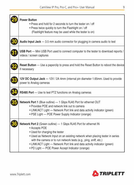
Power Button • Press and hold for 2 seconds to turn the tester on / off • Press twice quickly to turn the Flashlight on / off (Flashlight feature may be used while the tester is on)
Audio Input Jack — 3.5 mm audio connector for plugging in camera audio to test
USB Port — Mini USB Port used to connect computer to the tester to download reports / videos / screen captures
Reset Button — Use a paperclip to press and hold the Reset Button to reboot the device if necessary
12V DC Output Jack — 12V / 2A 4mm (internal pin diameter 1.65mm. Used to provide power to Analog cameras
RS485 Port — Use to test PTZ functions on Analog cameras
Network Port 1 (Blue outline) — 1 Gbps RJ45 Port for ethernet OUT • Provides POE and network link out to camera • LINK/ACT Light — Network Port link and data activity indicator (green) • PSE Light — POE Power Supply Indicator (orange)
Network Port 2 (Green outline) — 1 Gbps RJ45 Port for ethernet IN • Accepts POE • Used for charging the tester • Used as Network Input on an existing network when placing tester in series with the camera or to run network tests (e.g., ping, sniff, etc.) • LINK/ACT Light — Network Port link and data activity indicator (green) • PD Light — POE Power Accept Indicator (orange)
29
30
31
32
33
34
35
36

10 CamView IP Pro, Pro-C, and Pro+ User Manual
www.Triplett.com
3. BASIC OPERATION
3.1 Installing the Battery
The CamView IP Pro, Pro-C, and Pro+ use a rechargeable lithium-ion polymer battery. To ensure safety when transporting, always disconnect the battery from the tester. The device may leave the factory with one of the following two battery placements:
• The battery is placed inside tester and insulated from the contacts with a thin, plastic sheet. In this case, the user should open the battery cover, take out the battery, remove the plastic sheet, then put the battery back in, and put the battery cover back on.
• The battery is placed outside the tester. In this case, the user should open the battery cover, put the battery securely into the battery compartment, and put the battery cover back on.
Note — The tester will automatically turn on when the battery is properly placed in the device for the first time.
3.2 Charging the Battery
Be sure to fully charge the battery prior to first use. If the battery level is too low, the charge indica-tor will flash 3 times, and the device won’t turn on.
You should use the POE injector and ethernet cable provided by the manufacturer to charge the battery. To charge the unit, connect one end of the ethernet cable to the Data/Power-out Port on the POE Injector, then connect the other end of the ethernet cable to the Network Port 2 (Green outline) on the tester. Once you have connected the ethernet cable on both ends, plug in the pow-er cord for the POE Injector into a power outlet. Network Port 2 will light up with an orange light when the internal battery is recharging.
3.3 Frequently Asked Questions About the Battery
• The CamView IP Pro, Pro-C, and Pro+ use a lithium-ion polymer battery, which does not have a memory effect. Users can recharge the battery whenever they want.
• When recharging, the Charge Indicator on the tester will light up red. When the battery is fully charged, the light will turn off.
• Due to calculation deviation or other reason, the battery level can be as low as 90% when the charge light turns off. Users can ensure their battery Is fully charged by extending the charge time for up to 60 minutes.

CamView IP Pro, Pro-C, and Pro+ User Manual 11
www.Triplett.com
• The battery can also be charged using a POE switch or other POE power sources that meet the 802.3af / 802.3at standard. However, we strongly recommend using the original POE injector provided with your CamView IP Pro, Pro-C, or Pro+ unit. DO NOT USE A NON-STANDARD POE POWER SUPPLY TO CHARGE THE BATTERY—THIS CAN DESTROY THE TESTER.
3.4 Lanyard
Users can choose to install the lanyard. The lanyard can help handling the device, prevent dropping the device, avoid damage to the device, and prevent loss.
To install lanyard, put one end of the lanyard through the hole at the top of the device, turn back and go through the tri-glide button.Tighten the lanyard and confirm that it is locked.
3.5 Basic Starting Instruction
3.5.1 Turning the Device On and OffTo turn on the device, press and hold the Power Button for more than 2 seconds. The Power Indicator will light up green when the device is turned on.
To turn off the device, press and hold the Power Button for more than 2 seconds. When the device is turned off, the green Power Indicator light will turn off after the device is fully shut down. Users can also setup the idle auto power off feature.
3.5.2 Selecting Function ModeWhen the device is on, press the MODE button to switch to the Function Select menu. Press MODE multiple times or use the Arrow Keys to select a function.
Press the Right Arrow key to enter the selected function.
3.5.3 Using the FlashlightPress the Power Button twice quickly to turn the Flashlight on/off. You can use the Flashlight feature even if the tester is off.
The Flashlight will automatically turn off every time the device is turned on or off (to avoid draining the battery if the Flashlight is turned on accidentally).
WARNING The LEDs are high brightness LEDs. When the LEDs are on, do not look directly at them or point them at someone’s eyes as injury may occur.

12 CamView IP Pro, Pro-C, and Pro+ User Manual
www.Triplett.com
4. HOW TO USE YOUR CAMVIEW IP PRO, PRO-C, OR PRO+
4.1 Main Menu
When the CamView IP Pro-C/Pro+ first boots up, you will see the following Main Screen. (NOTE—CamView IP Pro Testers will show fewer options.)
You can navigate this screen using the Up or Down Arrow Keys. Once you have highlighted the function you want to use, press the Right Arrow Key to go to the Interface Screen for that feature.
4.2 Testing IP Cameras using the ONVIF Test Interface
4.2.1 OverviewThe ONVIF test function is designed to act as a three-step installation and trouble-shooting guide for IP Camera testing. It combines Ethernet tests, POE tests, IP settings, camera discovery, camera authorization, video display, PTZ control, camera settings, and more.
4.2.2 How to Connect the IP Camera to the TesterThere are three ways you can connect your IP cameras in order to test them:
OPTION 1For Power-over-Ethernet (POE) IP cameras, you can directly connect the camera to the Tester using the Tester’s Network Port 1 using an ethernet cable. The Tester will first detect the POE device and then supply power. The POE information and packet activitiy will be displayed on the screen. (You can verify incoming POE from the Switch by plugging that cable into Network Port 2.)
Note—When powering POE devices, the 12V output of the Tester is disabled. When a POE powered device requires more power than max power, the POE power output will ter-minate. The Tester’s PSE meets the 802.3af / 802.3at standard. The maximum power is 25.5W.

CamView IP Pro, Pro-C, and Pro+ User Manual 13
www.Triplett.com
OPTION 2 For non-POE IP cameras, the camera can either be powered using its own 12V power adapter or using the Tester’s 12V/2A power output. When using the Tester’s 12V/2A output, please use the 12V power cable supplied to connect the Tester’s 12V Output Port to the camera’s 12V power port. You can then connect the ethernet cable from the IP camera to the Tester’s Network Port 2. (Do not use Network Port 1 in this case as Network Port 1 may try to supply POE and disable the 12V port at the same time. Be sure to use Network Port 2 in this scenario.)
OPTION 3You can also connect to IP and Wireless IP cameras through a Network Switch. Simply connect an ethernet cable from the Switch to either the Tester’s Network Port 1 or Network Port 2. The network status will show on the Tester’s corresponding network port bar and icons after you turn the Tester on. The Tester supports MDI/MDIX connection.
Option 1 Option 2
Option 3

14 CamView IP Pro, Pro-C, and Pro+ User Manual
www.Triplett.com
4.2.3 Using the InterfaceOnce you have connected the IP Camera to the Tester using one of the options listed in the previous section, follow these steps to perform IP Camera testing:
STEP 1: Power Up the TesterPress the Power Button on the side of your CamView IP Pro, Pro-C, or Pro+ Tester to turn it on if it is not already powered on.
STEP 2: Select ONVIF TestOn the Main Menu, highlight “ONVIF Test” (press the MODE button to enter the Main Menu if you are not already on it). Once the “ONVIF Test” option is highlighted, press the Right Arrow Key to select the test.
STEP 3: Performing the Link TestThe screen should now be showing “1. Link Test” just below the Title Bar. (For more details about the Link Test screen, see pages 16 - 17.) Confirm activity on Network Port 1 (you should see a green light flashing on the ethernet port where the camera/network is connected to the Tester), adjust settings as necessary (e.g., modify the IP, DHCP, or link speed, etc.), then press the Right Arrow Key to move to the Discover screen.
STEP 4: Discovering the CameraWhen entering the Discover screen, the Tester software will broadcast an ONVIF discover message to discover ONVIF cameras. You may need to wait a few minutes for the Tester to find all of the cameras, particularly if it is a large network. The text above the list will show the number of cameras discovered. If there is more than one camera listed, Arrow Up/Down to highlight the camera you want to test.
Some cameras may not respond to the ONVIF discover request, or cannot reply due to different IP subnet settings. In this case, you should return to Step 2 and set the Tester’s local IP to be within the same subnet as the camera (remember, your Tester’s IP cannot be in conflict with other de-vices on the network). After that is done, enter Step 3 to try discovering the cameras again. If the camera(s) still cannot be discovered, then you can use the Manual Add function.
Manually Adding a Camera: To manually add a camera, you must know the camera’s exact IP and ONVIF service path. Once you have that information, press Zoom- while on the Discover screen, type the camera’s IP address into the field labelled “URL”, then press the TAB Key to add the ONVIF path.

CamView IP Pro, Pro-C, and Pro+ User Manual 15
www.Triplett.com
For example, if the camera’s IP address is 10.1.1.100, you would enter that into the “URL” field and then press the TAB Key. The Tester should then automatically append the IP address to include “.../onvif/device_service” at the end of the original 10.1.1.100 address. The final result will look like this: http://10.1.1.100/onvif/device_service.
Press Iris+ to accept the settings and return to the Discover screen.
You may also notice the Discover screen has a different set of On-Screen Options than what was on the Link Test screen, including Rediscover (which will run by pressing Focus-), Manual Add (accessible by pressing Zoom-), Refresh Pic (which will snap a new image from the camera by pressing Iris-), and so forth. Take a few minutes to review the On-Screen Options as you explore each screen.
STEP 5: Selecting and Accessing the Camera Once you have highlighted the camera you want to test on the Discover screen, press the RIGHT ARROW Key to select that camera.
If the camera requires a Username and Password, a notice will display on the right side of the screen saying “Authorization Required”. In this case, you will need to press Iris- to access the Username/Password screen. You can then open the flip keyboard to fill in the Username and Password (use the TAB Key to move between the fields, then press the RETURN Key when you are done).
Once you have accessed the camera, a snapshot from the camera will appear on the right side of the Discover screen. Information about the camera’s resolution, framerate, and compression method will show above the snapshot (see picture below).
Continued on page 18.

16 CamView IP Pro, Pro-C, and Pro+ User Manual
www.Triplett.com
Network Port 1 Status Information — Also referred to as the Blue Bar, all of the information for the camera connected to Port 1 (blue RJ45 port on the side of the Tester) will show in this row.
Network Port 2 Status Information — Also referred to as the Green Bar, all of the information from the network connected to Port 2 (green RJ45 port on the side of the Tester) will show in this row.
IP Test Information — Also referrred to as the Gray Bar, this area shows the IP informa-tion and status of the Tester and clients.
Available Operations for Link Testing — Follow the on-screen instructions to access or modify specific settings, such as: • Set Link Speed — Press Zoom+/- to modify link speed • Self DHCP — Press Focus- to enable Self-generating DHCP. Use if no network is set up yet and you are connecting directly to a camera. The Tester will set the local IP to static, start the DHCP server, and wait for a remote DHCP request from the camera. DO NOT USE if connecting through an existing network as this will cause an IP conflict. • Manual IP — Press SET button to enter Manual IP screen • Search DHCP — Press Iris- to have the tester request DHCP from an existing network. The server’s assigned address will show in the gray bar.
37
38
39
40
37
38 46
39
40
41 42 43 44
45

CamView IP Pro, Pro-C, and Pro+ User Manual 17
www.Triplett.com
Link Speed of Corresponding Port — The Link Speed displays above the bar icon. shows for each Port. The link speed can also be observed via the icon itself. • If the bar icon is gray, there is no network connection. It will also say “Link Down” as shown in the sample image. • If the bar icon is white, the tester is sensing and will display the link speed (10M/100M/1000M) and whether the connection is Full or Half Duplex.
Ethernet Data Flow Monitor — shows the current Ethernet traffic flow. • ¡ is the outgoing data flow in b/s, Kbps, and Mbps. • ¢ is the incoming data flow in b/s, Kbps, and Mbps.
Packet Loss Monitor — The displayed data shows the success rate. Normally this number is 100%. The color of the bars will differ according to the success rate. • Gray Bars — No Link • Green Bars — 100% of packet transfers successfully completed • Yellow Bars — 99%+ of packet transfers successfully completed • Orange Bars — 95% - 99% of packet transfers completed (i.e., up to 1% - 5% packet loss) • Red Bars — Less than 95% of packet transfers completed (i.e., 5% - 99% packet loss)
POE Power Supply Status — This icon is for Network Port 1 and indicates the POE power output status. The first line of text is output mode: • 12V — The device is outputting 12V and detecting PD at the same time. • PD. CLAS — The classification of the remote POE device. • PSE 48V — The remote POE device is being powered by the Tester. The second line of text shows the output power in Watts. When outputting power, the actual power consumption is decided by the remote device. The tester has a max power limit. When the remote device requires more power than max power, the output will terminate automatically.
POE Power Accept Status — This icon applies to network port 2, indicating the POE power acceptance status. The text displays the powering voltage as measured by the Tester. (E.g., PSE 48V — The Tester is being provided with POE at 48V.)
41
42
43
44
45
46

18 CamView IP Pro, Pro-C, and Pro+ User Manual
www.Triplett.com
CAMERA SETTINGS: While you are in the Discover screen, you can press the SET Key to enter the Camera’s Settings Screen.
The left side of the display shows the Setting’s Class, and the right side shows the details of the camera’s setting within that class. The classes and details are explained in the table at the bottom of this page.
Use Zoom +/- to move up or down to select the Class. To select right side items, use the Up and Down Arrow Keys. Use the Left and RIght Arrow Keys to adjust/change the high-lighted settings. Use the flip keyboard if you need to type in numbers, letters, or symbols (e.g., when updating the camera’s IP address to a static IP).
When you have finished, press Iris + to save your changes. The Tester will apply the new settings to the camera. If the camera accepts the new settings, the “Setup Successful” prompt will be displayed. Otherwise, failure information will be displayed.
NOTE — Some cameras must be rebooted to apply new settings.
Class Contents
Camera Info Device information including camera model, serial, brand, and other information. This information cannot be altered.
Scopes Name, location, model number, type(s) of encoder(s) (e.g., video, audio, PTZ), and the profile of the camera.
eth0 This can be set to Disabled, but is Enabled by default. Includes all the NIC 1 data (e.g., Mac Address, DHCP enabled/disabled, IP address, etc.)
wlan0 This can be set to Enabled, but is Disabled by default. Includes all the NIC 2 data (e.g., Mac Address, DHCP enabled/disabled, IP address, etc.)
Network Includes Hostname, Gateway, DNS, etc.
System This screen details which ports are used for the camera, and whether it is discoverable.

CamView IP Pro, Pro-C, and Pro+ User Manual 19
www.Triplett.com
You may also export a report about this camera by selecting the SCR Key. You can retrieve the report, along with any screenshots or recordings, by plugging the mini USB cable into the tester and then attaching it to your computer. Your computer will view the Tester as an external drive. See Appendix 1 for a sample report.
STEP 6: ONVIF Video Testing While on the Discover screen, press the Right Arrow Key to move to the “3. Video & PTZ” Test Screen (see example below). The Video & PTZ Test Screen will allow you to view a live video feed from your IP camera, control and test PTZ, and enter the camera’s setup settings.
When entering the Video & PTZ Test Screen. the Tester will automatically display the camera’s video stream. The video image will re-size to the reserved area of the screen.
ONVIF PTZ CONTROL: Pressing the SCR Key will switch to full screen video display mode, and all display information will be hidden. The video image will cover most of the screen area. Due to width to height ratio differences, part of the screen could be black with nothing to display. In full screen mode, use the Focus +/- and the Arrow Keys to control PTZ. Press the SET Key toaccess and change the stream profile settings (e.g., Baud Rate, Protocol [Pelco D, Samsung, Hikvision, etc.], Address, etc.)
ONVIF VIDEO DIGITAL ZOOM: On the video display screen, pressing the 1 Key will digitally zoom in, and pressing the Q Key will zoom out. When the image is partly shown, a chart will be displayed on the lower right corner that shows the display ratio. When the image is partly shown, pressing the E,S, D, and F Keys will move the viewing window to inspect different portions of the digitally zoomed image.
CAPTURING SCREEN SHOTS AND VIDEO: To capture a screen shot, press the A Key. To capture video, press the Z Key.

20 CamView IP Pro, Pro-C, and Pro+ User Manual
www.Triplett.com
4.3 Testing Analog Cameras
4.3.1 OverviewYou can test standard Analog (NTSC/PAL) cameras with the Pro model, NTSC/PAL & HD-CVI with the Pro-C model, or you can test NTSC/PAL, AHD & HD-TVI cameras if you have the Pro+ model.
4.3.2 How to Connect the Analog Camera to the TesterAnalog cameras are connected using the BNC In connector on the top of the Tester. If the camera is already providing a live-feed to the security personnel and you don’t want to remove their feed while you are testing the camera, you can then use the BNC Out to set up the Tester in series.
If the camera has PTZ, plug the PTZ cable into the RS485 Port on the side of the Tester.
Finally, you must ensure the camera has power.
There are two ways you can power your Analog camera. You can either plug the camera’s power cable into the 12V DC Output Jack on the side of the Tester (left image), or you can use the cam-era’s existing power source (right image).
NOTES — The Tester’s output power is 12V/2A. When the current exceeds the limit, power output will automatically stop. Be cautious when using cameras with high power IR lights.
Also, when Network Port 1 is connected to a POE-powered deviced, the 12V output is disabled.

CamView IP Pro, Pro-C, and Pro+ User Manual 21
www.Triplett.com
4.3.3 Using the Analog Camera Test InterfaceOnce you have connected the Analog Camera to the Tester and set up the camera’s power supply, follow these steps to perform Analog Camera testing:
STEP 1: Power Up the TesterPress the Power Button on the side of your CamView IP Pro, Pro-C, or Pro+ Tester to turn it on if it is not already powered on.
STEP 2: Select Analog Camera TestOn the Main Menu, highlight “Analog Camera Test” using the Down Arrow Key. Once the “Analog Camera Test” option is highlighted, press the Right Arrow Key to select the test.
Live video will show in the video display area. Due to varying image aspect ratios, the displayed image may not be full screen and some parts of the screen may be black (e.g., on the left and right side).
The signal information will show in the upper right of the screen, and will display the Format (e.g., NTSC, HD-TVI, etc.), and the resolution (e.g., 720x480), framerate (e.g., 30fps), and signal level.
STEP 3: Testing PTZWhile you are on the Analog Camera Test screen, you will notice the On-Screen Instructions give you the following options:
RECORDING SCREEN SHOTS AND SAMPLE VIDEOS: Press the A Key to save a Screen Shot to the Tester’s internal flash memory, or press the Z Key to record video to the Tester’s internal flash memory.
DIGITAL ZOOM: Opening the flip-keyboard and pressing the 1 or Q Keys will allow you to digitally zoom in and out.
PAN AND TILT: Press the Arrow Keys or Focus +/-, Zoom +/-, and Iris +/- to test the Pan, Tilt, Zoom functions on the camera. When the Tester is sending a Pan/Tilt signal to the camera, the Data Transmission Indicator on the top left of the Tester’s display will light up red. If you see that icon light up but do not see any movement on the camera, you will need to adjust the Tester’s settings to match the camera’s requirements regarding Protocol (e.g., Pelco D), Baud Rate (e.g., 2400), etc. The camera’s factory default settings should be in the camera’s user manual.

22 CamView IP Pro, Pro-C, and Pro+ User Manual
www.Triplett.com
To access and change the Tester’s settings to match the camera’s settings, press SET and then use the Arrow Keys to navigate the screen. (See image above.) When adjusting the parameters, press Iris- to restore previous values if you don’t want to save the setting. Once you have updated all of the settings, press SET again to save your changes. The changes will be applied immediately.
Protocol Select RS485 PTZ protocol. The tester supports many PTZ protocols.
Baud Rate RS485 communication baud rate.
Address Address of PTZ to control. Due to different camera manufacturer settings, the address may be offset by +/-1.Address range is dependent on the protocol.
Speed Expected PTZ speed, 10%-100%.
Set Preset Adjust this value, and then press Iris+ to save the camera’s current position to its internal storage. This function is provided by the camera. Refer to the camera’s manual for details.
Go Preset Adjust this value, and then press Iris+. The camera will go to the corresponding pre-saved position at maximum speed. This function is provided by the camera. Refer to the camera’s manual for details.

CamView IP Pro, Pro-C, and Pro+ User Manual 23
www.Triplett.com
4.3.4 Analog Video GeneratorOn the Main Menu, highlight “Analog Video Generator” (press the MODE button to enter the Main Menu if you are not already on it; press the Up or Down Arrow Keys to highlight it). Once the “Analog Video Generator” option is highlighted, press the Right Arrow Key to select the test.
Live video will show in the right side of the screen if you have the Analog Camera hooked up to the BNC In jack on the Tester. On the left side of the screen, you will see Pattern and Format options. (See image below.) You can adjust these options using your Arrow Keys. Press SET when you are done updating your options to save the changes.
Test Pattern Supports PM544 and EBU color bars and EIA1956 black and white test screen.
Format PAL/NTSC.
Output Image Left side.
Input Image Right side.
Input Format Format, resolution, and framerate of input video signal.
Input Level Input of the video’s level as displayed in dB. 0dB is the standard value (1vpp@75 ohms)

24 CamView IP Pro, Pro-C, and Pro+ User Manual
www.Triplett.com
4.3.5 Testing Remote Analog Monitors and Optical Transmitters/ReceiversYou can transmit generated video to the remote monitor or DVR using the BNC Out jack (see im-age below). This will allow you to test the cable and monitor by comparing the image quality on the Tester to the image quality on the monitor. You can do this with either a live feed from the camera when you are in the Analog Camera Test screen, or when you are viewing a test pattern in the Analog Video Generator screen.
You can also test the Optical Transmitters/Receivers in the circuit by connecting an optical video transmitter to the BNC Out on the Tester, then connecting that transmitter to an optical video receiver, and finally connecting the receiver to the BNC In on the Tester. (See image below.)

CamView IP Pro, Pro-C, and Pro+ User Manual 25
www.Triplett.com
4.4 Ethernet Cable TDR Test
4.4.1 OverviewThis feature is only available on the Pro-C and Pro+ models. It is primarily used to test the approximate cable length of an RJ45 cable by using a Time Domain Reflectometry (TDR) analysis meth-od. However, you can also use this feature to test for breaks, Skew, and Attenuation. The accuracy is to within one meter.
NOTES — Test results can be affected by temperature, moisture, cable diameter, and cable dielectric. Test results are only for reference, not for formal measurement.
Continuous measure is to help easily test multiple cables, and it will not increase the accuracy of the test.
When a cable is correctly terminated, there may be a stronger reflection from a cable junction along the cable’s length. This may result in a measurement that may be shorter than the actual cable length. We recommend that you disconnect the other end of the cable and measure from that end if this occurs.
4.4.2 Testing Length Using TDRTo measure a cable’s length, only one end of the cable should be connected to the Tester, and the other end should be left open.
STEP 1: Power Up the TesterPress the Power Button on the side of your CamView IP Pro-C or Pro+ Tester to turn it on if it is not already powered on.
STEP 2: Connect the Ethernet Cable to the TesterConnect one end of the Ethernet Cable to the Tester’s Network Port 1.

26 CamView IP Pro, Pro-C, and Pro+ User Manual
www.Triplett.com
47
48
49
50 51 52 53
Network Port 1 Icon
Tape Measure — Flashes just under the Network Port icon when a cable is being tested.
Network Port 2 icon
Cable Pairs — Both by number and color pattern.
Cable Pair Status — Test results for each pair are displayed here. • A solid horizontal line indicates pass-through (good cable; no breaks) • An X indicates the cable is not passing through. In a Length-Only test, this will always show X because the other end of the cable is not connected to the Tester. • A > symbol indicates a short of at least one wire in the pair. • “Test Failed” will display if the wire is in poor condition or for other unknown reasons.
Approximate Length of Cable — Length of cable (in meters) to termination or open.
Other Test Results — Attenuation, Skew, etc., will appear here.
47
48
49
50
51
52
53

CamView IP Pro, Pro-C, and Pro+ User Manual 27
www.Triplett.com
STEP 3: Access the TDR Test ScreenOn the Main Menu, highlight “RJ45 Cable TDR Test” (press the MODE button to enter the Main Menu if you are not already on it; press the Up or Down Arrow Keys to highlight it). Once the “RJ45 Cable TDR Test” option is highlighted, press the Right Arrow Key to select the test. (See page 26 for a complete description of each feature on this screen.)
Once you are on the Cable Test screen, press SET to activate/deactivate continuous testing; or press Zoom+ to test Port 1 once. See example results on below.
4.4.3 Testing for Breaks in Ethernet Cable Using TDRIf you are trying to test the quality of the cable itself instead of just getting the approximate length of the ethernet cable, you can perform a separate test.
STEP 1: Power Up the TesterPress the Power Button on the side of your CamView IP Pro-C or Pro+ Tester to turn it on if it is not already powered on.
STEP 2: Connect the Ethernet Cable to the TesterConnect one end of the Ethernet Cable to the Tester’s Network Port 1, and connect the other end of the Ethernet Cable to the Tester’s Network Port 2.
STEP 3: Access the TDR Test ScreenOn the Main Menu, highlight “RJ45 Cable TDR Test” (press the MODE button to enter the Main Menu if you are not already on it; press the Up or Down Arrow Keys to highlight it). Once the “RJ45 Cable TDR Test” option is highlighted, press the Right Arrow Key to select the test. (See page 26 for a description of each feature on this screen.)
Once you are on the Test screen, press Zoom+ to test Port 1 once. When testing is complete on Port 1, press Zoom- to test Port 2. The first example on page 28 shows the results from a good

28 CamView IP Pro, Pro-C, and Pro+ User Manual
www.Triplett.com
cable. The second example below shows the results from a cable with an open on the green pairs and the length to that open from each end of the cable.
NOTE — Do not use the Repeat Test feature when performing this test as the test results will be compromised.

CamView IP Pro, Pro-C, and Pro+ User Manual 29
www.Triplett.com
4.5 Network Analysis Tools
4.5.1 OverviewNetwork analysis is a combination of several network tools, including Ethernet Sniff, Subnet List, and Ping test.
4.5.2 Network Tools Test Screen and OperationOn the Main Menu, highlight “Network Tools” (press the MODE button to enter the Main Menu if you are not already on it; press the Up or Down Arrow Keys to highlight it). Once the “Network Tools” option is highlighted, press the Right Arrow Key to select the test. (See next page for a diagram of each feature on this screen.)
VERIFY & UPDATE IP, SUBNET, GATEWAY, AND DESTINATION: The list on the left side of the Network Tools screen will display the Tester’s current IP, Subnet Mask, Gateway, DNS, and Destination settings. To change these settings, select SET to access the IP Settings screen, then use the Arrow Keys and Flip Keyboard to make changes. Select Iris+ when you are done to confirm the changes and return to the Network Tools screen.
ETHERNET SNIFF: While you are on the Network Tools screen, press Focus+ to start the Sniff test. Once Ethernet Sniff is started, the Tester will listen to the network, waiting for broadcast data, detecting MAC and IP addresses. Unlisted new MAC and IP addresses will be added to the list. Press Focus+ again to end the test.
The format of the list is XX-XX-XX-XX-XX-XX I.I.I.I; where XX is a MAC address in HEX, and I is an IP address displayed in decimal.
Most network devices broadcast data packets periodically, identifying their presence. The Sniff function will detect this data and discover unknown network devices. The sniff function is detecting broadcasting data packets, so devices of any subnet and any kind can be found.
When connecting to an unknown device with an unknown IP address, first try using the DHCP server to distribute IP to the device. If the device is not requesting an IP address, then use this Sniff function to detect the device.
Detecting a device using the Sniff function may take 3 to 60 seconds, depending on the device broadcasting frequency, and the Tester will not detect a device if it remains silent.
NOTE — The sniff function does not detect uni-cast (point-to-point) packets.

30 CamView IP Pro, Pro-C, and Pro+ User Manual
www.Triplett.com
Tester’s Current Network Settings • IP/Mask - Tester’s IP Address and Subnet Mask. Select SET to change. • GW/DNS - Tester’s Gateway and DNS. Select SET to change. • Destination - Ping destination. When the bar is yellow, use the Flip Keyboard to change the information in this field. Both IP addresses and Domain Names are supported.
Information Display area — Results of testing will be listed here.
Set IP — Used to access the IP Settings screen to change the Tester’s settings between Static IP and DHCP
Sniff — Select Focus+ to run the Sniff test. This option will dim when other tests are running
List Subnet — Select Focus- to run the List Subnet test. This option will dim when other tests are running.
Ping — Select Zoom+ to run the Ping test. Press Zoom+ again to end the test. This option will dim when other tests are running.
53
54
55
56
57
58
53 55
56
57
58
54

CamView IP Pro, Pro-C, and Pro+ User Manual 31
www.Triplett.com
LIST SUBNET: To use the List Subnet function, IP and Mask should be set up, and the Subnet Mask should be 24bits wide (subnet size of 256 devices, or 8 bits). Refer to the instructions on page 29 if you need to update the IP, Subnet Mask, or Gateway.
While you are on the Network Tools screen, press Focus- to run the List Subnet function. The Tester will then scan the whole subnet. Devices being scanned must reply, so the discover rate is 100% if the device is operating normally. This List Subnet function will also measure the network latency, and display it in ms (milliseconds).
The List Subnet display format is: XX-XX-XX-XX -XX-XX I.I.I.I N ms. Where XX is the MAC address displayed in HEX, Iis the IP address displayed in decimal, and N is the network latency.
Compared to the network sniff function, this function cannot detect devices with different Subnet settings, but the same Subnet detection rate is 100%.
The List Subnet will take 1-10 seconds to finish. Press Focus- to exit the List Subnet function.
PING TEST: To use the Ping Test, IP, Subnet Mask, and Destination must be filled in. If the destination is a domain, then DNS/Gateway are also needed. Refer to the instructions on page 29 if you need to update the IP, Subnet Mask, or DNS/Gateway.
Use the Flip Keyboard when the destination section is yellow to edit the Destination.
While you are on the Network Tools screen, press Zoom+ to run the Ping Test.
The ping test displays result in chart form as shown on page 32. The first column is the latency grade; the second column is the number of responses at that latency grade; the third column is the respond time percentage; and the fourth column is the latency chart.
Press Zoom+ to exit the Ping Test.

32 CamView IP Pro, Pro-C, and Pro+ User Manual
www.Triplett.com
Ping 10.1.1.1 Average: 3ms
1ms 10 7% **
3ms 123 91% ****************
10ms 2 1% *
30ms 0 0%
0.1s 0 0%
0.3s 0 0%
1s 0 0%
3s 0 0%
Lost 0 0%
4.6 Recording, Reviewing, and Accessing Snapshots and Videos
4.6.1 OverviewThe Tester can take snapshots of or record input from video, then save the files to internal storage as either .jpg or .avi files. NOTE — Overlaid test details are not saved on the image.
4.6.2 Recording Screenshots and Video when Testing an IP CameraWhile on the Video & PTZ screen, select the A Key to take a screen shot, or the Z Key to record video. Press the Z Key a second time to stop the recording.
4.6.3 Recording Screenshots and Video when Testing an Analog CameraWhile in the Analog Camera Test screen, select the A Key to take a screen shot, or the Z Key to record video. Press the Z Key a second time to stop the recording.
4.6.4 Reviewing the Saved FilesWhile on the Main Menu, highlight “Record Playback” (press the MODE button to enter the Main Menu if you are not already on it; press the Up or Down Arrow Keys to highlight it). Once the “Record Playback” option is highlighted, press the Right Arrow Key to access the file folders. Follow the On-Screen Instructions to Delete, Play, Pause, and navigate the files.
4.6.5 Accessing the Saved Files from a ComputerWhile on the Main Menu, highlight and select “Settings”, then select “Start USB Storage”. Plug the USB cable into the side of the Tester and connect the other end to your computer. The Tester’s internal memory card will appear on your computer as an external hard drive.

CamView IP Pro, Pro-C, and Pro+ User Manual 33
www.Triplett.com
4.7 Device Settings and Updating the Firmware
4.7.1 OverviewThere are many other features in the Tester that you can adjust or view, including the screen’s language, Auto Shutoff delay, Serial Number, and so forth. There may also be times when you need to update the firmware or export files to a computer.
4.7.2 Viewing and Changing SettingsOn the Main Menu, highlight “Settings” (press the MODE button to enter the Main Menu if you are not already on it; press the Up or Down Arrow Keys to highlight it). Once the “Settings” option is highlighted, press the Right Arrow Key to access the Device Settings screen. (See next page for a screen shot of the Device Settings screen.)
AUTO POWER OFF: Use the Left and Right Arrow Keys to change the setting and press Iris+ to apply.
KEYPAD TONE: Use the Left and Right Arrow Keys to change the setting and press Iris+ to apply. The Keypad Tone setting does not affect the Audio Test function.
SCREEN LANGUAGE: Use the Left and Right Arrow Keys to change the setting and press Iris+ to apply. The tester supports multiple languages, including French and Spanish.
SCREEN BACKLIGHT: Use the Left and Right Arrow Keys to change the setting and press Iris+ to apply For outdoor use, a higher brightness will have better contrast, while a lower brightness will consume less battery power.
SYSTEM TIME: When the field is highlighted, use Focus+/- to change the hours in 24-hour time, Zoom+/- to change the minutes, and the Left and Right Arrow Keys to change the seconds, then press Iris+ to apply the changes.
SYSTEM DATE: When the field is highlighted, use Focus+/- to change the year, Zoom+/- to change the month, and the Left and Right Arrow Keys to change the day, then press Iris+ to apply the changes.

34 CamView IP Pro, Pro-C, and Pro+ User Manual
www.Triplett.com
4.7.3 Upgrading Firmware and Identifying Current Firmware VersionIP and Analog camera standards are constantly evolving, therefore it is important that you keep your Tester up-to-date with the most recent firmware. Follow these steps to update the firmware:
STEP 1: Power Up the TesterPress the Power Button on the side of your CamView IP Pro, Pro-C, or Pro+ Tester to turn it on if it is not already powered on.
STEP 2: Connect to the InternetPlug an ethernet cable into Network Port 2, and plug the other end of the ethernet cable into a network that has Internet access. Wait for the light on the LINK/ACT on Network Port 2 to flash before moving on to the next step. (If the network you are plugging into is using DHCP, the Tester will automatically detect the IP Settings. Otherwise, you will need to manually apply the IP settings. Consult your Network Administrator if you need assistance.)
STEP 3: Select the Settings ScreenOn the Main Menu, highlight “Settings” using the Down Arrow Key. Once the “Settings” option is highlighted, press the Right Arrow Key to access the Device Settings screen.
STEP 4: Select the System Upgrade functionWhile on the Device Settings screen, scroll down to the System Upgrade option using the Up or Down Arrow Keys, then press the Right Arrow Key to access the Check Upgrade screen. Your current firmware version will show on this screen.

CamView IP Pro, Pro-C, and Pro+ User Manual 35
www.Triplett.com
STEP 5: Run the Firmware UpgradeIf you have internet access, the Tester will automatically check for new firmware updates when you initially land on the Check Upgrade screen. If, however, you see an error that states “Network Failed” (see screenshot below), first confirm that the network you have plugged into does have internet access and is set to DHCP. If the network does have internet access and the network is supposed to be providing DHCP service to the Tester, you will need to press SET to get to the IP Settings screen, and then just toggle over to “Static IP” and then back to “Use DHCP” by press-ing the Right Arrow Key twice. Once “Use DHCP” is highlighted again, press Iris+ to apply the settings. The Check Upgrade should run immediately. The Tester will connect to the software up-grade server and try to find a new software version automatically.
When a new version is found, the new version number and current version number will be dis-played. Press Focus+ to enter the download screen. The download process is fully automatic, and an integrity check is automatically executed upon download completion. After this process, the tester will return to the upgrade screen automatically.
An upgrade download may take seconds to dozens of minutes, depending on the network speed. Please use a broadband connection to upgrade.This will save you valuable time.
After the update has successfully downloaded, a “Start Upgrade” prompt will be displayed on the screen. Press Zoom+ to start the upgrade. The system will reboot automatically then enter the upgrade screen. Press SET to start. Follow the on-screen prompts to continue the process.
NOTES — Confirm the battery level is at least 30%. It is a good choice to connect the charger when upgrading to avoid power loss during the upgrade process. Also, do not open battery cover, remove the battery, or press the Reset button while upgrading as doing so may cause system failure, and the device may not be able to boot up again.

36 CamView IP Pro, Pro-C, and Pro+ User Manual
www.Triplett.com
4.7.4 Exporting ReportsAny screen shots, video, or ONVIF IP camera reports you have saved on your Tester can be exported to your computer.
STEP 1: Power Up the TesterPress the Power Button on the side of your CamView IP Pro, Pro-C, or Pro+ Tester to turn it on if it is not already powered on.
STEP 2: Connect the Tester to the ComputerPlug the mini-USB end of the cable into the Tester, and plug the standard USB end of the cable into your computer.
STEP 3: Select the Settings ScreenOn the Main Menu, highlight “Settings” (press the MODE button to enter the Main Menu if you are not already on it; press the Up or Down Arrow Keys to highlight it). Once the “Settings” option is highlighted, press the Right Arrow Key to access the Device Settings screen.
STEP 4: Select the Start USB Storage functionWhile on the Device Settings screen, scroll down to the Start USB function using the Up or Down Arrow Keys. Once the option is highlighted, press the Right Arrow Key. The Tester’s flash drive should now be accessible as an external drive on your computer, and you should see the image below on the Tester’s screen while the connection is in place.
NOTES — Due to data sharing problems, the USB storage function is off by default. When using USB Storage, do not press MODE or the power key as doing so will cause the USB storage device to be unplugged from the host computer, and you may lose data. To disconnect the USB connection from a computer, eject or unmount the disk from the host system before disconnecting the cable.

CamView IP Pro, Pro-C, and Pro+ User Manual 37
www.Triplett.com
4.8 Audio Tests
The Tester is equipped with an audio test function. It can be used to test microphones or other audio devices.
Use the supplied 3.5mm audio cable to connect audio device. The black clip is for the ground, the red clip is for the signal connection. Be sure to connect the ground first to avoid loud noises during connection.
If connected successfully and the Tester is powered on, the audio will be heard through the Tester’s internal speaker.
4.9 RS485 Data Monitor
The Tester can detect whether the PTZ at the Control Center (i.e., the joystick or software that is used by the Security Staff to pan / tilt / zoom a camera) is reaching the camera by using the Data Monitor feature.
STEP 1: Power Up the TesterPress the Power Button on the side of your CamView IP Pro, Pro-C, or Pro+ Tester to turn it on if it is not already powered on.
STEP 2: Connect the Tester’s RS485 Port to the Camera’s RS485 HookupYou can use the Alligator clips with the RS485 plug to do this. Plug the RS485 connector into the Tester, and click the Alligator clips onto the PTZ wires on the camera.
STEP 3: Select the Data Monitor ScreenOn the Main Menu, highlight “Data Monitor” (press the MODE button to enter the Main Menu if you are not already on it; press the Up or Down Arrow Keys to highlight it). Once the “Data Monitor” option is highlighted, press the Right Arrow Key to access the Data Monitor screen.
STEP 4: Adjust Tester’s SettingsSelect the correct Baud Rate by pressing Zoom+/- , then move the joystick or software controls in the Control Center. A hexadecimal representation of the commands from the joystick/software controls will appear if the commands are making it to the Tester.

CamView IP Pro, Pro-C, and Pro+ User Manual 39
www.Triplett.com
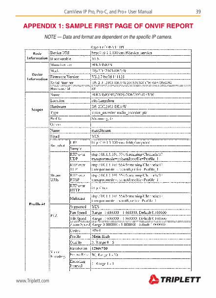
APPENDIX 1: SAMPLE FIRST PAGE OF ONVIF REPORT
NOTE — Data and format are dependent on the specific IP camera.

40 CamView IP Pro, Pro-C, and Pro+ User Manual
www.Triplett.com
APPENDIX 2: TECHNICAL SPECIFICATIONS
PORTS
Network Ports (2) 10M/100M/1G RJ45 ports (Blue is POE Out; Green is POE In)
I/O Ports (2) BNC ports (Video IN and Video OUT), (1) RS485, (1) Audio In, (1) USB, (1) Reset Button
IP CAMERA TEST FEATURES
Protocols ONVIF 2.4.1, RTSP, RTP
Ethernet Tests 10M/100M/1G Ethernet link test, loop detect, Ethernet traffic flow monitor, link quality test
IP Configurations Static IP / DHCP client / DHCP server
IP Camera Tests Discover camera, real-time video, camera configuration, PTZ control, audio test, full screen preview, and 8x digital zoom; snapshot, record video (recording original data stream), store ONVIF camera reports
AHD, TVI, HD-CVI, & SD ANALOG CAMERA TEST FEATURES
SD Signal Format NTSC / PAL
HD Video Signal Formats AHD & TVI (Pro+ model only); HD-CVI (Pro-C model only)
Resolutions D1, 720P, 1080P
Signal Level 1Vpp
Camera Tests Real-time video, PTZ control, audio test, full-screen preview, and 8x digital zoom; snapshot, record video (H.264)
PTZ CONTROLS
Protocol More than 30 protocols including Dahua, Pelco-D/P, Samsung, Panasonic, Lilin, Yaan etc.
Baud Rate 150, 300, 600, 1200, 2400, 4800, 9600, 19200bps
DETECTION
TDR Tests 0~150m network cable length measurement (resolution 1m), cable pair status
PTZ Test Data Monitor to detect RS485 Communication from control room console to camera
POE Tests PD test (tester accepts POE power, displays voltage)
PSE test (tester provides POE power, displays power)
Network Analysis Sniff, list subnet, ping
Analog Video Generator Generate PAL / NTSC video signals of various test patterns
Record Playback Support local playback of recorded video and view screenshots

CamView IP Pro, Pro-C, and Pro+ User Manual 41
www.Triplett.com
SYSTEM
Screen 4.0 inch TFT 800*RGB*480(WVGA) resolution, 16.7M color, backlight brightness adjust-able
Operation Method Power key, 12 control keys, QWERTY flip-open keyboard with 45 keys
Auto Power Off Disable / 5~60 minutes
Keyboard Tone Enable / Disable
Software Supports online upgrades
POWER
Power Input POE source or POE injector (Green RJ45 port)
POE Injector Input AC100~230V 50~60Hz, output 48V/15w
Battery Dedicated battery, user replaceable, 7.4V lithium-ion polymer battery, capacity 22.2Wh
Power Output POE (802.3af, 802.3at) (Blue RJ45 port), DC12V 2A
Time Charging time 3~4 hours, max working time 10 hours
OTHER
Internal Storage 8GB flash
LED Light (2) 35lm LED lights
Working Temperature -10°C ~+55°C
Working Humidity 30%~90%
Dimensions 190mm x 113mm x 37mm
Weight 1.6kg

42 CamView IP Pro, Pro-C, and Pro+ User Manual
www.Triplett.com
WARRANTY AND TECHNICAL SUPPORT
Triplett / Jewell Instruments extends the following warranty to the original purchaser of these goods for use. Triplett warrants to the original purchaser for use that the products sold by it will be free from defects in workmanship and material for a period of (1) one year from the date of purchase.
This warranty does not apply to any of our products which have been repaired or altered by unauthorized persons in any way or purchased from unauthorized distributors so as, in our sole judgment, to injure their stability or reliability, or which have been subject to misuse, abuse, misapplication, negligence, accident or which have had the serial numbers altered, defaced, or removed. Accessories, including batteries and fuses, are not covered by this warranty.
To register a claim under the provisions of this warranty, please contact the distributor from which you purchased the product from for warranty consideration.
ALL WARRANTIES IMPLIED BY LAW ARE HEREBY LIMITED TO A PERIOD OF THREE YEARS FROM DATE OF PURCHASE, AND THE PROVISIONS OF THE WARRANTY ARE EXPRESSLY IN LIEU OF ANY OTHER WARRANTIES EXPRESSED OR IMPLIED.
The purchaser agrees to assume all liability for any damages and bodily injury which may re-sult from the use or misuse of the product by the purchaser, his employees, or others, and the remedies provided for in this warranty are expressly in lieu of any other liability Triplett may have, including incidental or consequential damages.
Some states (USA ONLY) do not allow the exclusion or limitation of incidental or consequential damages, so the above limitation or exclusion may not apply to you No representative of Triplett / Byte Brothers or any other person is authorized to extend the liability of Triplett in connection with the sale of its products beyond the terms hereof.
Triplett reserves the right to discontinue models at any time, or change specifications, price or design, without notice and without incurring any obligation.
This warranty gives you specific legal rights, and you may have other rights which vary from state to state.
Contact Information: Phone: 1-800 Triplett Email: [email protected]


ABOUT TRIPLETT
Triplett Test Equipment and Tools has been desiging specialized test equipment for over 100 years.
Triplett was acquired by Jewell Instruments in 2007. Jewell Instruments is a world leader in the manufacturing and distribution of advanced sensors, controls, panel meters, and avionics. Jewell provides custom solutions for the aerospace, medical, industrial, marine, telecommunications, and railroad industries.
Jewell’s experienced engineering team works with customers and end-users to develop top-of-the-line products that meet or exceed all customer requirements.
The company has two manufacturing facilities—one in Manchester, New Hampshire, and the other in Barbados, West Indies. Both facilities maintain the most stringent manufacturing requirements. The Barbados facility also provides the cost-competitive advantage of offshore manufacturing
Jewell is committed to continuing the legacy started by Ray L. Triplett, producing only the high-est quality, most technologically advanced, rugged, and reliable test equipment products in the marketplace.
Jewell Instruments Headquarters Manchester, NH
USA


