
Camera Space Shadow Maps for Large Virtual Environmentsbib.irb.hr/datoteka/570987.12_CSSM.pdf ·...
11
1 Camera Space Shadow Maps for Large Virtual Environments Ivica Kolic 1 ⋅ Zeljka Mihajlovic 2 1 Ivica Kolić Systemcom d.o.o. mail: [email protected] 2 Željka Mihajlović University of Zagreb, Faculty of Electrical Engineering and Computing, Croatia Unska 3, 10 000 Zagreb, Croatia mail: [email protected] Abstract This paper presents a new single-pass shadow mapping technique that achieves better quality than the approaches based on perspective warping, such as perspective, light-space and trapezoidal shadow maps. The proposed technique is appropriate for real-time rendering of large virtual environments that include dynamic objects. By performing operations in camera space, this solution successfully handles the general and the dueling frustum cases, and produces high-quality shadows even for extremely large scenes. This paper also presents a fast non-linear projection technique for shadow map stretching that enables complete utilization of the shadow map by eliminating wastage. The application of stretching results in a significant reduction in unwanted perspective aliasing, commonly found in all shadow mapping techniques. Technique is compared with other shadow mapping techniques, and the benefits of the proposed method are presented. The proposed shadow mapping technique is simple and flexible enough to handle most of the special scenarios. An API for a generic shadow mapping solution is presented. This API simplifies the generation of fast and high-quality shadows. Keywords: Shadow maps, Real-time shadows, Dynamic shadows, Virtual environments 1 Introduction A shadow is one of the most important elements for achieving realism in virtual environments. Over the years, many real-time shadow-generation approaches have been developed. The most well- known approaches are fake and planar shadows, shadow volumes (Crow 1977), and shadow mapping (Williams 1978). This paper primarily focuses on the shadow mapping technique that is recognized as the most important shadow generation tool today because of its simplicity, generality, and predictability. The basic shadow mapping principle involves two steps. In the first step, the shadow map is generated by storing the depth of the scene from the point of view of the light. In the second step, the scene is rendered regularly; however, for every drawn pixel, the shadow map is consulted to determine whether that particular pixel is directly visible to the light. This is accomplished by comparing the distance of the shadow map from the light with the distance of the pixel (depth) from the light. In this paper, we will present a new shadow mapping approach, termed camera space shadow maps (CSSM). This approach acquires the shadow map in a simple manner by directly using a camera. We will also describe a method for the maximum utilization of the shadow map to prevent wastage and significantly reduce the perspective aliasing of the shadow near the camera. The organization of the remainder of this paper is as follows: Previous work in the area of shadow mapping is summarised in Section 2, while the new CSSM approach is described in Section 3. Section 4 presents a novel pixel-accurate shadow map stretching technique. In Section 5, the experimental results are discussed, and the new CSSM approach is compared with other approaches. Details of the
Transcript of Camera Space Shadow Maps for Large Virtual Environmentsbib.irb.hr/datoteka/570987.12_CSSM.pdf ·...

1
Camera Space Shadow Maps for Large Virtual Environments
Ivica Kolic1 ⋅⋅⋅⋅ Zeljka Mihajlovic
2
1 Ivica Kolić Systemcom d.o.o. mail: [email protected] 2 Željka Mihajlović University of Zagreb, Faculty of Electrical Engineering and Computing, Croatia
Unska 3, 10 000 Zagreb, Croatia
mail: [email protected]
Abstract This paper presents a new single-pass
shadow mapping technique that achieves better
quality than the approaches based on perspective
warping, such as perspective, light-space and
trapezoidal shadow maps. The proposed technique
is appropriate for real-time rendering of large
virtual environments that include dynamic objects.
By performing operations in camera space, this
solution successfully handles the general and the
dueling frustum cases, and produces high-quality
shadows even for extremely large scenes. This
paper also presents a fast non-linear projection
technique for shadow map stretching that enables
complete utilization of the shadow map by
eliminating wastage. The application of stretching
results in a significant reduction in unwanted
perspective aliasing, commonly found in all
shadow mapping techniques. Technique is
compared with other shadow mapping techniques,
and the benefits of the proposed method are
presented. The proposed shadow mapping
technique is simple and flexible enough to handle
most of the special scenarios. An API for a generic
shadow mapping solution is presented. This API
simplifies the generation of fast and high-quality
shadows.
Keywords: Shadow maps, Real-time shadows,
Dynamic shadows, Virtual environments
1 Introduction
A shadow is one of the most important elements for
achieving realism in virtual environments. Over the
years, many real-time shadow-generation
approaches have been developed. The most well-
known approaches are fake and planar shadows,
shadow volumes (Crow 1977), and shadow
mapping (Williams 1978).
This paper primarily focuses on the shadow
mapping technique that is recognized as the most
important shadow generation tool today because of
its simplicity, generality, and predictability. The
basic shadow mapping principle involves two
steps. In the first step, the shadow map is generated
by storing the depth of the scene from the point of
view of the light. In the second step, the scene is
rendered regularly; however, for every drawn pixel,
the shadow map is consulted to determine whether
that particular pixel is directly visible to the light.
This is accomplished by comparing the distance of
the shadow map from the light with the distance of
the pixel (depth) from the light.
In this paper, we will present a new shadow
mapping approach, termed camera space shadow
maps (CSSM). This approach acquires the shadow
map in a simple manner by directly using a camera.
We will also describe a method for the maximum
utilization of the shadow map to prevent wastage
and significantly reduce the perspective aliasing of
the shadow near the camera.
The organization of the remainder of this paper is
as follows: Previous work in the area of shadow
mapping is summarised in Section 2, while the new
CSSM approach is described in Section 3. Section
4 presents a novel pixel-accurate shadow map
stretching technique. In Section 5, the experimental
results are discussed, and the new CSSM approach
is compared with other approaches. Details of the

2
generic shadow mapping API (Kolic 2010) are
provided in Section 6, while section 7 presents the
conclusions and future work.
2 Previous Work
Shadow mapping techniques can be classified as
single-pass and multi-pass approaches, based on
the number of passes required to create the shadow
map. Single-pass approaches are fast and less
demanding; however, in general, they cannot be
used for large-scale environments because it is
difficult to achieve good shadow map distribution
for both near and distant shadows. Several
approaches such as perspective shadow maps
(PSM) (Stamminger and Drettakis 2002; Kozlov
2004), light space shadow maps (LiSPSM)
(Wimmer et al. 2004), trapezoidal shadow maps
(TSM) (Martin and Tan 2004, Martin 2008), and
soft shadow maps (Mo et al. 2007) have been
developed to address this issue. However, a single-
pass robust solution capable of handling most of
the special cases has not yet been proposed. Multi-
pass approaches, on the other hand, are widely used
today due to their ability to provide good-quality
shadows in most of the special cases (such as
dueling frustum). In these approaches, the scene is
split into smaller segments for which individual
shadow maps are acquired and applied. The main
disadvantages of these approaches are low speed,
high memory consumption, and discontinuity in
shadow quality in the region where separate
shadow maps connect. Hence, their usage is mainly
reserved for scenes with only one dominant light,
such as the Sun. Two popular multi-pass
approaches are cascaded shadow maps (Dimitrov
2007) and parallel split shadow maps (Zhang et al.
2006). A detailed description of shadow mapping
approaches can be found in Nealen (2002) and
King (2004).
3 Camera space shadow maps
The aim of this paper is to provide the first
complete shadow mapping solution that, in a single
pass, always produces the highest quality shadow
map for any type of light/scene/camera and various
special cases. In theory, the highest-quality shadow
map would be achieved if every pixel on the screen
has exactly one corresponding texel in the shadow
map. This level of quality can only be achieved by
ray tracing. Hence, in this paper, a considerably
simpler definition is used: the highest shadow
mapping quality is achieved when the resulting
shadow map is completely free of wastage, and
every texel is reserved exclusively for shadow
passing through visible space.
The shadow mapping solution must also provide an
easy method to control distance-based shadow
distribution. This can be implemented by allowing
the specification of a distance value for which a
certain percentage of the shadow map should be
reserved. For example, the shadow within 20 m
from the camera should occupy 50% of the shadow
map. This cannot be achieved using linear
transformation.
Existing perspective warping approaches (such as
TSM and LiSPSM) were designed primarily for the
general case, and they cannot efficiently handle
complex dueling frustum cases and various other
possible lighting conditions. Therefore, a new,
more generic approach will be presented, in which
it is easy to perceive the configuration to be used
for special cases, such as dueling frustum, camera
without far clipping and the most difficult case of
the large omnidirectional light located within
visible space.
3.1 Construction of shadow map
The main principle of perspective warping-based
approaches involves treating geometry with the
projections of both camera and light. Thus, a
shadow closer to the camera gets more shadow map
space. The goal must be decided on the basis of the
manner in which regular geometry is treated by the
camera. The goal must be to transform shadow
mapping geometry into camera space, using the
camera matrix for shadow map warping. However,
it is not possible to simply transform, rotate, and
scale geometry because this would cause loss of
light occlusion and depth information. Depth
information is not very relevant because it can
always be calculated separately in a vertex or even
pixel shader, but the preservation of occlusion
information is essential. We, however, made the
following observation: If shadow casting geometry
is projected on any arbitrary plane, the limitations
on translation, rotation, and scaling are avoided,
and the geometry can be transformed into camera
space without losing occlusion information. Once
the geometry is in camera space, perspective
warping occurs automatically.
Fig. 1 demonstrates a new, simple method for
acquiring the shadow of the entire visible space
using only one projection plane and the camera
itself. Projection plane P is placed such that it
touches the lower point of the viewing frustum at
the near clipping distance and the opposite point at
the far clipping distance. However, today, a
common scenario involves rendering of enormous
scenes where far clipping is not done at all. In this
case, the shadow plane should be parallel with the
appropriate side of the view frustum, as shown in
the figure. Fig. 1 also suggests that if a light is
located slightly in front of the viewer, the starting
point for the plane should be the upper point of the
viewing frustum at the near clipping distance.

3
Fig. 1. Basic principle of CSSM. The projective plane P is
located within the view frustum V. The case with the limited
view frustum is shown on the left. When the view frustum is not
far clipped (right), the projective plane is parallel to the side of
the view frustum.
The dueling frustum case is shown in Fig. 2. From
the figure on the left, it is clearly visible that a
single projection plane cannot provide good
shadow projection into visible space, and hence,
multiple planes must be used, as shown in the
figure on the right. In the 2D representation shown
in the figure, only two planes are used; however, in
the actual 3D case, four projective planes are
required (top, bottom, left, and right).
Fig. 2. The dueling frustum case cannot be solved with only one
plane (left), where the unshadowed area is marked as N. The
correct approach requires multiple planes with a common point
t, as shown on the right.
As seen from the figures, various shadow mapping
operations are performed in camera space and the
camera itself is used to capture the shadow map.
This is in contradiction with all other shadow
mapping approaches where the shadow map is
exclusively captured from the point of view of the
light. The proposed approach is therefore
appropriately termed camera space shadow maps
(CSSM).
In the general case, CSSM is acquired in the
following manner:
• Rotate (roll) the camera around its Z-axis so
that the light always originates from above (as
shown in Fig. 1).
• Change the FOV (Field of view) angles of the
rotated camera so that the entire view frustum
of the original camera can fit within the new
view frustum.
• Design a plane that passes through the two
lower points of the near clipping plane and the
two upper points of the far clipping plane, as
shown in Fig. 1. If the source of light is located
slightly in front of the camera, opposite points
should be used and the FOV angle of the X-axis
of the camera must be slightly increased, so that
the plane seen from the point of view of the
light covers the entire view frustum.
• Light-project shadow casting geometry on the
constructed plane.
• Use the projection matrix of the rotated camera
to acquire the shadow map.
In the dueling frustum case, CSSM is acquired in
the following manner:
• Determine a point on a near clipping plane by
applying the projection of the camera on the
position/direction of the source of light.
• Construct four planes that cross through the
acquired point and all the edges of the far
clipping plane.
• Light-project geometry on the projective planes
using geometry shader. For each projective
plane, a projected triangle must be created with
clipping distances of two neighbouring planes
set at every vertex. Thus, the clipper will
remove unnecessary geometry, and the
geometry shader will always generate a
predictive number of triangles as output.
• Use the camera projection matrix to acquire the
shadow map.
3.2 Distribution of shadow map
A close examination of Fig. 1 reveals a problem
commonly found in all perspective warping
approaches: approximately half of the shadow map
is allocated for the shadow that resides within the
near clipping distance (n) from the start of the
viewing frustum. An example is as follows:
• Near clipping occurs at 0.2 m (n)
• Far clipping occurs at 1000 m (f).
In this example, the first half of the shadow map is
reserved for a very small shadow located between
0.2 and 0.4 m from the camera: [n, 2n>, and the
second half of the shadow map is reserved for an
enormous shadow area located between 0.4 and
1000 m: <2n,f].
Almost every approach (PSM, TSM, LiSPSM)
addresses this problem of near shadow
oversampling by moving the camera backward,
thus increasing the near clipping distance. The
effect of this method can be observed in Fig. 3.
4
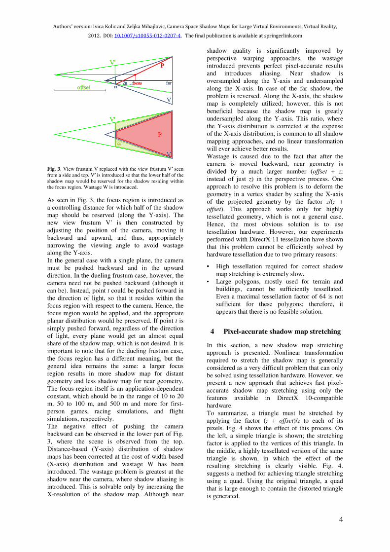
Fig. 3. View frustum V replaced with the view frustum V� seen
from a side and top. V� is introduced so that the lower half of the
shadow map would be reserved for the shadow residing within
the focus region. Wastage W is introduced.
As seen in Fig. 3, the focus region is introduced as
a controlling distance for which half of the shadow
map should be reserved (along the Y-axis). The
new view frustum V� is then constructed by
adjusting the position of the camera, moving it
backward and upward, and thus, appropriately
narrowing the viewing angle to avoid wastage
along the Y-axis.
In the general case with a single plane, the camera
must be pushed backward and in the upward
direction. In the dueling frustum case, however, the
camera need not be pushed backward (although it
can be). Instead, point t could be pushed forward in
the direction of light, so that it resides within the
focus region with respect to the camera. Hence, the
focus region would be applied, and the appropriate
planar distribution would be preserved. If point t is
simply pushed forward, regardless of the direction
of light, every plane would get an almost equal
share of the shadow map, which is not desired. It is
important to note that for the dueling frustum case,
the focus region has a different meaning, but the
general idea remains the same: a larger focus
region results in more shadow map for distant
geometry and less shadow map for near geometry.
The focus region itself is an application-dependent
constant, which should be in the range of 10 to 20
m, 50 to 100 m, and 500 m and more for first-
person games, racing simulations, and flight
simulations, respectively.
The negative effect of pushing the camera
backward can be observed in the lower part of Fig.
3, where the scene is observed from the top.
Distance-based (Y-axis) distribution of shadow
maps has been corrected at the cost of width-based
(X-axis) distribution and wastage W has been
introduced. The wastage problem is greatest at the
shadow near the camera, where shadow aliasing is
introduced. This is solvable only by increasing the
X-resolution of the shadow map. Although near
shadow quality is significantly improved by
perspective warping approaches, the wastage
introduced prevents perfect pixel-accurate results
and introduces aliasing. Near shadow is
oversampled along the Y-axis and undersampled
along the X-axis. In case of the far shadow, the
problem is reversed. Along the X-axis, the shadow
map is completely utilized; however, this is not
beneficial because the shadow map is greatly
undersampled along the Y-axis. This ratio, where
the Y-axis distribution is corrected at the expense
of the X-axis distribution, is common to all shadow
mapping approaches, and no linear transformation
will ever achieve better results.
Wastage is caused due to the fact that after the
camera is moved backward, near geometry is
divided by a much larger number (offset + z,
instead of just z) in the perspective process. One
approach to resolve this problem is to deform the
geometry in a vertex shader by scaling the X-axis
of the projected geometry by the factor z/(z +
offset). This approach works only for highly
tessellated geometry, which is not a general case.
Hence, the most obvious solution is to use
tessellation hardware. However, our experiments
performed with DirectX 11 tessellation have shown
that this problem cannot be efficiently solved by
hardware tessellation due to two primary reasons:
• High tessellation required for correct shadow
map stretching is extremely slow.
• Large polygons, mostly used for terrain and
buildings, cannot be sufficiently tessellated.
Even a maximal tessellation factor of 64 is not
sufficient for these polygons; therefore, it
appears that there is no feasible solution.
4 Pixel-accurate shadow map stretching
In this section, a new shadow map stretching
approach is presented. Nonlinear transformation
required to stretch the shadow map is generally
considered as a very difficult problem that can only
be solved using tessellation hardware. However, we
present a new approach that achieves fast pixel-
accurate shadow map stretching using only the
features available in DirectX 10-compatible
hardware.
To summarize, a triangle must be stretched by
applying the factor (z + offset)/z to each of its
pixels. Fig. 4 shows the effect of this process. On
the left, a simple triangle is shown; the stretching
factor is applied to the vertices of this triangle. In
the middle, a highly tessellated version of the same
triangle is shown, in which the effect of the
resulting stretching is clearly visible. Fig. 4.
suggests a method for achieving triangle stretching
using a quad. Using the original triangle, a quad
that is large enough to contain the distorted triangle
is generated.

5
Fig. 4. Triangle stretching is achieved by generating a quad that
is large enough to contain the distorted triangle. Each pixel of
the quad is tested to determine if it lies within the original
triangle.
The easiest method to construct an appropriate
quad is to detect the minimal and maximal
projection positions and the upper left and right
projection points, as shown in the figure. This
approach also works for a quad when the triangle is
clipped by a near clipping plane.
If each pixel of a quad is transformed back in the
space of the original (undistorted) triangle and
tested to determine if it lies within the original
triangle, then, pixel-accurate stretching is achieved.
This is tested by calculating the barycentric UV
coordinates, which are also beneficial for correct
texture coordinate interpolation when bit-masking
is used (for rendering plants, fences, etc.). This
process results in fast and pixel-accurate stretching
that completely eliminates shadow map wastage.
The actual process of testing whether pixel p lies
within the original triangle is shown in Fig. 5. After
z is determined using only the y-coordinate of the
pixel, the correct (unstretched) x-coordinate and the
accompanying point p� on a projection plane can be
determined. The next step involves projecting point
p� on point p
� located on the plane of the original
triangle, using the simple line vs. plane test. Then,
the perspective-correct UV coordinates can be
determined, and the actual test can be performed:
stretched pixel p belongs to the triangle if the UV
coordinates are positive and their sum is smaller
than 1. At this point, perspective-correct texture
coordinates can be interpolated if necessary, for
potential bit masking. Although this appears to be a
complicated process, the resulting pixel shader
script contains only a few lines of code since all the
complex calculations are performed only once per
triangle within the geometry shader.
Fig. 5. Determining if pixel p belongs to the stretched triangle T.
After z is determined, the correction factor for the X-axis is easy
to calculate.
It is also important to note that pixel stretching is
only necessary for shadow triangles that are near
the camera. As the distance of the triangles from
the camera increases, the apparent effect of the
deformation decreases. In fact, beyond a certain
distance (dependent on the focus range and triangle
size), pixel accurate stretching is not needed since
the deformation effect is not noticeable, and
shaders can switch to the regular approach in which
stretching is implemented only on vertex basis. The
triangles that are situated at a sufficiently large
distance should be marked in geometry shader.
This will enable pixel shader to be aware that
simple implementation should be used. In this case,
the output of the geometry shader is the original
triangle and not the quad.
This action is very important because it
significantly decreases the creation time of the
shadow map, and pixel-accurate stretching is
performed only for a few triangles that cast a
shadow near the camera.
When the X-axis distribution is fixed, bad
perspective aliasing near the camera is reduced
significantly. Along the X-axis, the shadow map is
completely utilized and additional increase of
shadow map resolution would not yield better
results (except at highly angled surfaces). At this
point, the Y-axis distribution is a major problem,
since the entire length of the scene must be fitted
on it. Hence, we propose the usage of longer but
narrower shadow maps to ensure that the fill rate
remains unchanged, while there is a significant
improvement in the general shadow quality. This
will add slight near shadow aliasing. If the usage of
additional shadow map is not desired, the existing
shadow map should at least be rotated in the
perspective process to allow the longer side of the
shadow map to be reserved for the Y-axis (distance
distribution). It is important to note that shadow
map stretching is not applied in the dueling frustum
case, where the shadow map is already fully
utilized.

6
Fig. 6. Comparison between general case for TSM (left) and CSSM (centre) techniques. Dueling frustum CSSM case is shown on the right.
Accompanying shadow maps are shown below. The scene is a ‘Pavilion Garden’.
The effects of pixel-accurate shadow map
stretching are:
• Near shadow quality is significantly improved
by eliminating wastage.
• Far shadow quality is improved by increase in
the Y-axis resolution.
5 Experimental results
In this section, tests are performed to determine the
speed of the newly proposed approach, and
comparisons with other perspective warping
approaches are shown. The results obtained in this
section will help us to choose the optimal
approaches for the generic shadow mapping API.
The most important difference between TSM and
CSSM is shown in Fig. 6. Due to pixel-accurate
stretching, CSSM provides better solutions for near
shadow. Unbiased comparison between TSM and
CSSM was ensured in the case where the focus
region was equalized. It is obvious that without
stretching, both approaches would produce an
almost identical result. The dueling frustum case
for TSM is not shown because this approach is not
designed to work in scenes that are presumed to be
large. Here, scene analysis was not done and small
640 × 640 shadow maps were used to easily
observe the effect of aliasing.
The performance was tested using an ATI Radeon
HD 5770 graphics card, at a rendering resolution of
640 × 640 pixels, using the palm tree model
consisting of 10624 triangles, as shown in Fig. 7.
The scene was rendered from two angles to capture
view from first person (FPS) for the general and the
dueling frustum cases at different shadow map
resolutions, since the usage of large shadow maps
is common. The general case was tested with and
without pixel-accurate stretching. The reference
frame rate is provided for the case when there is no
lighting in order to facilitate the evaluation of the
amount of time taken by regular deferred rendering
passes. The frame rates are specified in Table 1 and
Fig. 7.
From Table 1, the fictive frame rate can be
calculated exclusively for shadow map rendering.
This data is shown in Table 2.
From table 2, we can conclude that at higher
shadow map resolutions, pixel-accurate shadow
map stretching is approximately three times slower
than the approach without stretching (one plane or
TSM). However, in Fig. 8, the improvement in
shadow quality is substantial when stretching is
used. The dueling frustum case shows very good
shadow quality and high speed when a single plane
is used. This proves that an increase in geometry
shader activity (or instancing) caused by the usage
of multiple projection planes has no significant
effect on performance but has a significant effect
on quality. This result was expected and it can be
attributed to the same reason that results in fast
cube mapping: unnecessary triangles are instantly
clipped.
7
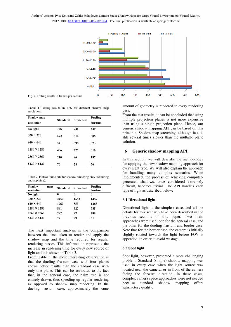
Fig. 7. Testing results in frames per second
Table 1 Testing results in FPS for different shadow map
resolutions
Shadow map
resolution Standard Stretched
Dueling
frustum
No light 746 746 529
320 × 320 572 514 388
640 × 640 541 398 373
1280 × 1280 406 225 316
2560 × 2560 210 86 187
5120 × 5120 70 28 70
Table 2. Fictive frame rate for shadow rendering only (acquiring
and applying).
Shadow map
resolution Standard Stretched
Dueling
frustum
No light 0 0 0
320 × 320 2452 1653 1456
640 × 640 1969 853 1265
1280 × 1280 891 322 785
2560 × 2560 292 97 289
5120 × 5120 77 29 81
The next important analysis is the comparison
between the time taken to render and apply the
shadow map and the time required for regular
rendering passes. This information represents the
increase in rendering time for every new source of
light and it is shown in Table 3.
From Table 3, the most interesting observation is
that the dueling frustum case with four planes
shows better results than the standard case with
only one plane. This can be attributed to the fact
that, in the general case, the palm tree is not
entirely drawn, thus speeding up regular rendering
as opposed to shadow map rendering. In the
dueling frustum case, approximately the same
amount of geometry is rendered in every rendering
pass.
From the test results, it can be concluded that using
multiple projection planes is not more expensive
than using a single projection plane. Hence, our
generic shadow mapping API can be based on this
principle. Shadow map stretching, although fast, is
still several times slower than the multiple plane
solution.
6 Generic shadow mapping API
In this section, we will describe the methodology
for applying the new shadow mapping approach for
every light type. We will also explain the approach
for handling many complex scenarios. When
implemented, the process of achieving computer-
generated shadows, once considered extremely
difficult, becomes trivial. The API handles each
type of light as described below:
6.1 Directional light
Directional light is the simplest case, and all the
details for this scenario have been described in the
previous sections of this paper. Two main
approaches were used: one for the general case, and
the other for the dueling frustum and border case.
Note that for the border case, the camera is initially
slightly rotated towards the light before FOV is
appended, in order to avoid wastage.
6.2 Spot light
Spot light, however, presented a more challenging
problem. Standard (simple) shadow mapping was
used in every case when the light source was
located near the camera, or in front of the camera
facing the forward direction. In these cases,
complex camera space approaches were not needed
because standard shadow mapping offers
satisfactory quality.

8
Fig. 8. Testing model of a palm tree. TSM case that contains wastage is shown on the left. Middle shows CSSM approach that performs
pixel-accurate shadow map stretching. Dueling frustum CSSM case is shown on the right. In every case shadow map resolution was 640 ×
640.
Table 3. Percentage increase in rendering time for every new
source of light at different shadow map resolutions.
Shadow map
resolution Standard Stretched
Dueling
frustum
No light 0 0 0
320 × 320 30.42 45.14 36.34
640 × 640 37.89 87.44 41.82
1280 × 1280 83.74 231.56 67.41
2560 × 2560 255.24 767.44 182.89
5120 × 5120 965.71 2564.29 655.71
Compared to directional light camera space shadow
mapping, spot light required some modification.
Near and far clipping distances had to be
recalculated by intersecting visible frustum at the
appropriate points. Fig. 8 shows a situation where
the camera origin is not lighted. In this case, a new
focus range must be recalculated to prevent
unnecessary wastage. Therefore, the new near
clipping is done at n� and not n. In this case, the
original focus range f is replaced with the
corresponding focus range f�. Parameter f0
represents the theoretical focus range in the
absence of near clipping, and serves as a reference.
In most implementations, this range can be
considered to be equal to f because the near
clipping distance n is very small. The approximate
new focus range is now calculated as:
( ) nfrfanf ′+′′−=′ /1
In addition, in certain scenarios, depending on the
angle and direction of the light, dueling frustum
can be handled as a general case. This occurs when
light is positioned in the dueling frustum area but
the origin of the camera is not lighted due to the
direction of light.
6.3 Omnidirectional light
Omnidirectional light was the most challenging
case. The following approaches were used:
• General case with one plane for every non-
dueling frustum case.
• Dueling frustum with four planes when light is
located behind the camera.
• Special dueling frustum with eight planes
when light is located in front of the camera.

9
Fig. 9. Fixing the focus region. If camera is not lighted,
alternative near clipping is done at n� with corresponding focus
range f�.
Fig. 10. Most problematic omnidirectional light case where
eight planes are used.
• Simple projection on four sides of a
tetrahedron when the light source is small or is
very near the camera.
The special dueling frustum case is shown in Fig.
10. It is the most difficult case, which combines
dueling frustum CSSM approach with four
additional back projection planes. Initially, we used
CSSM for front and back planes. However,
although the resulting shadow quality was excellent
for near and far shadows, it was bad for medium
distance shadow. Hence, we decided to use CSSM
for front planes and standard shadow mapping for
back planes. The distance d where CSSM ends and
standard shadow mapping begins is calculated so
that the shadow quality at the endpoint of CSSM
approach is the same as the standard shadow
mapping quality of the back planes (note that
standard shadow mapping quality is uniform over
the entire back plane and it does not change as
CSSM quality does).
Fig. 11. Shadow map organization for various special cases. For
the general case, long and narrow effect is achieved by splitting
shadow map into columns. Green projection planes indicate the
usage of standard shadow mapping, while red planes represent
the usage of CSSM approach.
Simple projection on four planes of tetrahedron is
used for the case when small light sources are
located within the viewing frustum.
6.4 API implementation
It is necessary for the API to satisfy the following
constraints:
• The usage should be extremely simple (even
simpler than standard shadow mapping) so that
the main API function can be implemented in
standard graphic libraries (DirectX, OpenGL)
and everyone will have access to high quality
shadows out-of-the-box.
• The API should also be very fast (single-pass)
having a speed measurable with standard
shadow mapping, but with better quality.
• Only one shadow map should be used for
various cases and an additional depth buffer
should not be required (so that the memory
usage remains minimal).

10
Fig. 12. Large scene of Citadel is presented without shadows (left) and with CSSM shadows (right)
.
• The API should work even on DirectX 9
hardware.
• The shader implementation should be minimal
and easy to incorporate in the existing
rendering systems.
Due to the introduction of the DirectX 9 constraint,
the general cases for all the light types were
implemented using multiple planes, as shown in
Fig. 11. However, we noted that after the
elimination of wastage, the shadow map used
should be long and narrow. This is in contradiction
with the constraint related to shadow map count
and size, which meant that after planar projection,
pieces of the shadow map should be rearranged for
the regular-sized shadow map to appear like a long
and narrow one (shadow map was split into
multiple columns). Every special case approach,
except the standard dueling frustum, required the
rearrangement of projections within the shadow
map, and some form of clip biasing so that errors in
the region where different projections meet would
not be visible. The placement and clipping of
projection planes for all considered approaches is
shown in Fig. 11. The API implementation consists
of a single function stored in a dynamic linked
library (CSSM.dll), and it is available in Kolic
(2010). Figure 12 depicts a large scene with and
without shadows.
7 Conclusion
Shadow mapping has evolved greatly over the last
few decades and can be considered to have reached
its peak. Simply stated, no linear transformation
will ever be good enough to create better shadow
mapping; hence, there is a need for an alternative
solution using non-linear transformations or
multiple plane projections.
A new perspective shadow map warping approach
has been presented, which is simple and flexible
enough to handle most of the special cases
(compared to TSM and LiSPSM, which are
designed only for the general case).
A new non-linear transformation system based on
the idea of generating quads that are large enough
to contain the distorted triangles and performing
checks in pixel shader has been presented.
The generic shadow mapping API solution was
implemented in a single pass in order to minimize
the expensive render call and changes to render
targets. In rare situations requiring multiple
instances of geometry, the fastest available
methods such as geometry shader and instancing
were used. The API satisfied the four main
constraints: single-pass, single shadow map
(without z-buffer), highest quality (in the form of
complete shadow map utilization), and arbitrary
distance distribution. All these qualities make the
API suitable for implementation in standard
graphic libraries such as DirectX and OpenGL and
for presentation of virtual worlds in real-time.

11
CSSM works well in situations where objects are
evenly distributed around the camera (typical for
FPS games). However, in some situations, such as
flight, where terrain is observed from a great
height, CSSM will not perform very well because
most of the shadow map will be used for the empty
space between the camera and the ground. Varying
the focus range based on distance from the ground
would greatly improve quality; however, in this
case, the ideal solution would be to use the plane of
the ground for shadow projection, which is similar
to the ideas presented by Chong and Gortler
(2004). Therefore, future work could involve
extending the API to accept information about
dominant surface in the scene, and deciding
whether to reserve parts of the shadow map for this
type of projection. Further optimization would
involve implementation of scene analysis, which is
similar to the work by Lauritzen et al. (2011) and
which would automatically detect dominant
surfaces. Further investigation could be pursued if
this analysis and plane construction is done on
GPU and combined with the ideas presented by
Lefohn et al. (2007). Also, instead of just having
fixed focus range, optimal focus range and camera
clipping could be determined dynamically by
sampling minimal, maximal and average scene
depth (in spite of having a few frames delay) which
is very easy to achieve if multi-resolution rendering
is used.
Like every other perspective warping approach,
CSSM suffers from shadow flickering; however,
the effect is significantly less due to wastage
elimination. This is not a major problem since
shadow map filtering and smoothing is common
today. In addition, scenes are becoming
increasingly dynamic today; therefore, even stable
shadow mapping approaches are not immune to
flickering. In fact, in a dynamic scene with
considerable vegetation influenced by the wind,
using stable cascaded shadow maps will actually
produce the worst flickering because the shadow
map utilization is not as high as with CSSM. Future
work could also include further investigation of
shadow flickering.
By using the shadow mapping API presented in this
paper, computer-generated shadows that were once
considered very difficult and slow have become
trivial, fast, and appropriate for large virtual
environments.
Acknowledgements The used test scenes are a
‘Pavilion Garden’ model from Google 3D
warehouse, credit goes to Tan Tunny. Citadel and
palm tree models are from Google 3D warehouse
as well.
References
Chong H, Gortler S (2004) A Lixel for Every Pixel, In
Proceedings Fifteenth Eurographic Workshop on Rendering
Crow FC (1977) Shadow algorithms for computer graphics. In
Proceedings of SIGGRAPH ’77, George J., (Ed.), vol. 11,
pp 242–248
Dimitrov R (2007) Cascaded shadow maps, NVIDIA
Corporation'07, Available at http://developer.nvidia.com,
King G (2004) Shadow Mapping Algorithms, Technical report,
NVIDIA Corporation. Available at
http://download.nvidia.com,
Kolic I (2010) Camera space shadow maps (CSSM), Available
at http://free-zg.t-com.hr/cssm/
Kozlov S (2004) Perspective shadow maps: Care and feeding. In
GPU Gems: Programming Techniques, Tips and Tricks for
Real-Time Graphics, pp 217-244
Lauritzen A, Salvi M, Lefohn A (2011) Sample distribution
shadow maps, In Symposium on Interactive 3D Graphics
and Games (I3D '11), pp. 97-102
Lefohn AE, Sengupta S, Owens JD (2007) Resolution-matched
shadow maps, ACM Trans. Graph. 26, 4, Article 20,
October 2007
Martin T, Tan TS (2004) Anti-aliasing and continuity with
trapezoidal shadow maps. In Proceedings of the
Eurographics Symposium on Rendering
Martin T (2008) Trapezoidal Shadow Maps (TSM) – Recipe
http://www.comp.nus.edu.sg/~tants/tsm/TSM_recipe.html.
Mo Q, Popescu V, Wyman C (2007) The Soft Shadow
Occlusion Camera, In Proceedings of the 15th Pacific
Conference on Computer Graphics and Applications (PG
'07), IEEE Computer Society, pp. 189-198
Nealen AV (2002) Shadow Mapping and Shadow Volumes:
Recent Developments in Real-Time Shadow Rendering,
Project report for Advanced Computer Graphics: Image
Based Rendering (CS514), University of British Columbia
Stamminger M, Drettakis G (2002) Perspective shadow maps. In
Proceedings of SIGGRAPH, pp. 557–562
Williams L (1978) Casting curved shadows on curved surfaces.
In Proceedings of SIGGRAPH ’78, vol. 12, pp. 270–274
Wimmer M, Scherzer D, Purgathofer W (2004) Light space
perspective shadow maps. In Proceedings of Eurographics
Symposium on Rendering
Zhang F, Sun H, Xu L, Lun K (2006) Parallel-split shadow
maps for large-scale virtual environments. In Proceedings of
the 2006 ACM international conference on Virtual reality
continuum and its applications, pages 311–318, ACM Press.

![Lecture 18: Shadows€¦ · Approaches to Improve Shadows • Hard Shadows – Adaptive Shadow Maps [Fernando, Fernandez, Bala, Greenberg] – Shadow Silhouette Maps[Sen, Cammarano,](https://static.fdocuments.us/doc/165x107/6025c28f585c5e56e22db8b1/lecture-18-approaches-to-improve-shadows-a-hard-shadows-a-adaptive-shadow-maps.jpg)


![Alias-Free Shadow Maps - NVIDIA Research Homepageresearch.nvidia.com/.../files/pubs/2004-06_Alias-Free-Shadow-Maps/... · Alias-Free Shadow Maps ... I.3.7 [Computer Graphics]: Three-Dimensional](https://static.fdocuments.us/doc/165x107/5aa5dbc37f8b9ae7438e123a/alias-free-shadow-maps-nvidia-research-shadow-maps-i37-computer-graphics.jpg)