cam switches - Morekstuff.morek.eu/CATALOGUES/APATOR/4G switches ENG.pdf · SWITCHGEAR 166 Table...
44
SWITCHGEAR 162 4G cam switches SWITCHGEAR
-
Upload
vuongkhanh -
Category
Documents
-
view
218 -
download
3
Transcript of cam switches - Morekstuff.morek.eu/CATALOGUES/APATOR/4G switches ENG.pdf · SWITCHGEAR 166 Table...

SWITCHGEAR
162
4Gcam switches
SWITCHGEAR

ENERGY SAFELY SWITCHED
163
ENERGY SAFELY SWITCHED
cam switches

SWITCHGEAR
164 GENERAL INFORMATION
4G-series cam switches are low voltage switches, designed according to the latest knowledge about switchgear and using the achievements of modern engineering. Only high quality insulation and contact materials have been used in these products. Basic components and units are standardized and mass-produced, making it possible to make switches performing any switching programs, and short delivery terms.Switches can be produced in many versions and have various applications. They conform all requ-irements for low voltage switches in industry, mining, shipbuilding, etc. They can be used as hand-operated switches in transformer stations, control switchboxes and boards, switchgears made of cast iron or other metals, welding machines and similar devices.4G series switches are characterized by small external dimensions, powerful switching capabilities, long contact life and high mechanical stability, and resistance to short-lasting overloads. When additionally protected with fuses, they are also resistant to dynamic effects of short-circuit currents.
APPLICATION
Cam switches can be used in main and auxiliary circuits, especially: � as switches for electric motors for switching and controlling the drives with single- and three-phase motors, as star-
delta switches, reversing switches and switches for changing the rotational speed, etc., � in auxiliary, controlling, signalling and measuring circuits, manufactured according to the required switching program, � as breaker switches, change-over switches and tap switches, for example for transformers and electric welding machines, � as switchgroups, for example to connect resistors and heating elements, � as change-over switches working as push-buttons with automatic returning to an off position, � as switch disconnectors.
CONFORMITY WITH STANDARDS
4G-series cam switches fully comply with the requirements of the following standards: PN-93/E-06150/10, PN-93/E-06150/30, IEC 947-1, IEC 947-3.These switches have a BBJ certificate for “B” safety mark, Recognition Certificate of the Polish Register of Shipping, and “CE” Declaration of conformity of the European directive 73/23/EEC.
DIVISION
Basic division of switches and their marking is based on the rated current. Further division, based on external dimensions of the switches, enables to distinguish three groups characterized by overall dimensions. Each group has the same knobs, front plates and spacing for mounting holes.
Group A0 A1 A2 A3
Switch type 4G10 4G16 4G25 4G40 4G63 4G80 4G100
Rated current le 10 16 25 40 63 80 100
DESIGN
Depending on the switching program, every cam switch consists of a certain number of switching elements, which can be easily assembled together. Switching elements’ bodies are made of plastics based on melami-ne, especially resistant to the effects related to creep currents and electric arcs.
Table 118. DIVISION INTO GROUPS
GE
NE
RA
L IN
FOR
MA
TIO
N
ENERGY SAFELY SWITCHED
165
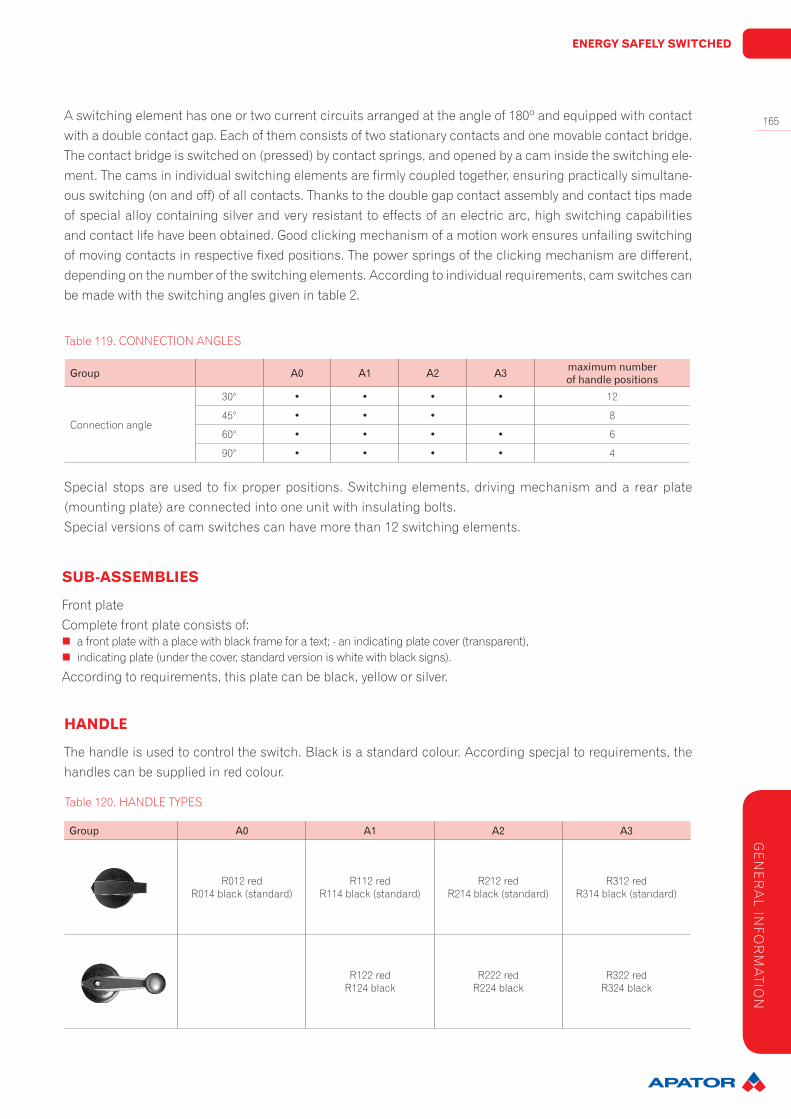
Group A0 A1 A2 A3
R012 redR014 black (standard)
R112 redR114 black (standard)
R212 redR214 black (standard)
R312 redR314 black (standard)
R122 redR124 black
R222 redR224 black
R322 redR324 black
Group A0 A1 A2 A3 maximumnumberofhandlepositions
Connection angle
30° • • • • 12
45° • • • 8
60° • • • • 6
90° • • • • 4
Special stops are used to fix proper positions. Switching elements, driving mechanism and a rear plate (mounting plate) are connected into one unit with insulating bolts.Special versions of cam switches can have more than 12 switching elements.
SUB-ASSEMBLIES
Front plateComplete front plate consists of:
� a front plate with a place with black frame for a text; - an indicating plate cover (transparent), � indicating plate (under the cover, standard version is white with black signs).
According to requirements, this plate can be black, yellow or silver.
HANDLE
The handle is used to control the switch. Black is a standard colour. According specjal to requirements, the handles can be supplied in red colour.
A switching element has one or two current circuits arranged at the angle of 180º and equipped with contact with a double contact gap. Each of them consists of two stationary contacts and one movable contact bridge. The contact bridge is switched on (pressed) by contact springs, and opened by a cam inside the switching ele-ment. The cams in individual switching elements are firmly coupled together, ensuring practically simultane-ous switching (on and off) of all contacts. Thanks to the double gap contact assembly and contact tips made of special alloy containing silver and very resistant to effects of an electric arc, high switching capabilities and contact life have been obtained. Good clicking mechanism of a motion work ensures unfailing switching of moving contacts in respective fixed positions. The power springs of the clicking mechanism are different, depending on the number of the switching elements. According to individual requirements, cam switches can be made with the switching angles given in table 2.
Table 119. CONNECTION ANGLES
Table 120. HANDLE TYPES
GE
NE
RA
L INFO
RM
ATIO
N

SWITCHGEAR
166 Table 121. TECHNICAL DATA
1) - cosφ = 0,65
Parametersswitchtype
4G10 4G16 4G25 4G40 4G63 4G80 4G100 4G200 4G400 4G630 4G800 4G1200
Rated insulation voltage Ui V 690 690 690 690 690 690 690 690 690 690 690 690
Rated impulse withstand voltage Uimp
kV 4 4 4 6 6 6 6 8 8 8 8 8
Rated thermal current Ith A 16 20 25 50 63 80 125 200 400 630 800 1200
Short-circuit protectionRated breaking capacity of fuse links with high breaking capacity
10 kAsk A – 25 25 50 63 80 125 200 400 630 2x400 2x630
25 kAsk A – 25 25 50 63 80 125 160 315 500 2x400 2x630
40 kAsk A – 25 25 50 63 80 125 160 315 400 500 2x400
63 kAsk A – 25 25 36 50 63 100 160 250 355 400 630
75 kAsk A – 25 25 36 50 63 100
Mechanical durability (number of cycles) 3x10⁶ 3x10⁶ 3x10⁶ 3x10⁶ 3x10⁶ 3x10⁶ 3x10⁶ 2x10⁵ 2x10⁵ 2x10⁵ 2x10⁵ 2x10⁵
Terminal bolts Maximum cross-sec-tion of connecting conductors mm2
M32 x 2,5
M4 2 x 4
M4 2 x 6
M52 x 10
M5 2 x 10
M625
2 x M6 50
M6 –
M10 –
M12 –
M16 –
M16 –
Short duration load capacity
1 s A 220 430 690 920 1600 1600 2600 3300 6500 9500 12000 18000
10 s A 70 145 240 290 600 650 850 1100 2000 3000 4000 6100
30 s A 40 90 160 200 375 400 500 640 1200 1800 2400 3500
60 s A 30 75 125 155 285 300 360 460 850 1250 1600 2450
Breaking capacity
660 V - cosφ = 0,65 A – 190 – – – – – 640 – – – –
660 V - cosφ = 0,35 A – – 250 490 500 500 650 – – – – –
600 V - cosφ = 0,35 A – 200 260 500 610 610 – – – – – –
500 V - cosφ = 0,35 A 1001) – – – – – 900 900 – – – –
500 V - cosφ = 0,75 A – – – – – – – – 1100 1100 1200 1800
Switch discon-nectors Utilization category AC2Rated power of three-phase loads
3 x 220 V~ kW 5,2 7 9 14 23 29 37 72 150 150 150 150
3 x 380 V~ kW 9 12,5 15,5 24 39 50 63 125 260 260 260 260
3 x 500 V~ kW 11,8 17 20 33 52 66 84 165 340 340 340 340
3 x 660 V~ kW 15,5 22 27 43 69 86 110 210 400 400 400 400
Switch disconnec-tors for motorsUtilization category AC3, AC23Rated power of three-phase motors
3 x 220 V~ kW 3 4,5 7,5 12,5 18,5 21 – 27,5 27,5 27,5 27,5 27,5
3 x 380 V~ kW 5 8 13 21 32 37 – 47 47 47 47 47
3 x 500 V~ kW 6 11 17 27 42 48 – 62 62 62 62 62
3 x 660 V~ kW 6 11 17 27 55 60 – 80 80 80 80 80
Switch disconnec-tors for motorsUtilization category AC23 Rated power of three-phase motors
3 x 220 V~ kW – – – – – – 27,5 27,5 27,5 27,5 27,5 27,5
3 x 380 V~ kW – – – – – – 47 47 47 47 47 47
3 x 500 V~ kW – – – – – – 62 62 62 62 62 62
3 x 660 V~ kW – – – – – – 80 80 80 80 80 80
Switch disconnec-tor for motors,category of utility AC3, AC23(30 connections/h).Rated power of one-phase (dipolar) motors.
110 V~ kW 0,8 1,3 2,1 3,6 5,3 6 – – – – – –
220 V~ kW 1,7 2,6 4,3 7,2 10,6 12,1 – – – – – –
380 V~ kW 2,8 4,6 7,5 12 18,5 21,1 – – – – – –
Auxiliary switch disconnectorsUtilization category AC14 Rated swit-ching current Ie (1 pole)
110 V~ A 11 20 25 50 63 72 – – – – – –
220 V~ A 8 20 25 40 50 50 – – – – – –
380 V~ A 3,5 16 20 40 45 45 – – – – – –
660 V~ A 2,5 8 8,5 10 10 10 – – – – – –
Type of operation – Continuous duty
TEC
HN
ICA
L D
ATA

ENERGY SAFELY SWITCHED
167
Parametersswitchtype
4G10 4G16 4G25 4G40 4G63 4G80 4G100 4G200 4G400 4G630 4G800 4G1200
Rated insulation voltage Ui V 690 690 690 690 690 690 690 690 690 690 690 690
Rated impulse withstand voltage Uimp
kV 4 4 4 6 6 6 6 8 8 8 8 8
Rated thermal current Ith A 16 20 25 50 63 80 125 200 400 630 800 1200
Short-circuit protectionRated breaking capacity of fuse links with high breaking capacity
10 kAsk A – 25 25 50 63 80 125 200 400 630 2x400 2x630
25 kAsk A – 25 25 50 63 80 125 160 315 500 2x400 2x630
40 kAsk A – 25 25 50 63 80 125 160 315 400 500 2x400
63 kAsk A – 25 25 36 50 63 100 160 250 355 400 630
75 kAsk A – 25 25 36 50 63 100
Mechanical durability (number of cycles) 3x10⁶ 3x10⁶ 3x10⁶ 3x10⁶ 3x10⁶ 3x10⁶ 3x10⁶ 2x10⁵ 2x10⁵ 2x10⁵ 2x10⁵ 2x10⁵
Terminal bolts Maximum cross-sec-tion of connecting conductors mm2
M32 x 2,5
M4 2 x 4
M4 2 x 6
M52 x 10
M5 2 x 10
M625
2 x M6 50
M6 –
M10 –
M12 –
M16 –
M16 –
Short duration load capacity
1 s A 220 430 690 920 1600 1600 2600 3300 6500 9500 12000 18000
10 s A 70 145 240 290 600 650 850 1100 2000 3000 4000 6100
30 s A 40 90 160 200 375 400 500 640 1200 1800 2400 3500
60 s A 30 75 125 155 285 300 360 460 850 1250 1600 2450
Breaking capacity
660 V - cosφ = 0,65 A – 190 – – – – – 640 – – – –
660 V - cosφ = 0,35 A – – 250 490 500 500 650 – – – – –
600 V - cosφ = 0,35 A – 200 260 500 610 610 – – – – – –
500 V - cosφ = 0,35 A 1001) – – – – – 900 900 – – – –
500 V - cosφ = 0,75 A – – – – – – – – 1100 1100 1200 1800
Switch discon-nectors Utilization category AC2Rated power of three-phase loads
3 x 220 V~ kW 5,2 7 9 14 23 29 37 72 150 150 150 150
3 x 380 V~ kW 9 12,5 15,5 24 39 50 63 125 260 260 260 260
3 x 500 V~ kW 11,8 17 20 33 52 66 84 165 340 340 340 340
3 x 660 V~ kW 15,5 22 27 43 69 86 110 210 400 400 400 400
Switch disconnec-tors for motorsUtilization category AC3, AC23Rated power of three-phase motors
3 x 220 V~ kW 3 4,5 7,5 12,5 18,5 21 – 27,5 27,5 27,5 27,5 27,5
3 x 380 V~ kW 5 8 13 21 32 37 – 47 47 47 47 47
3 x 500 V~ kW 6 11 17 27 42 48 – 62 62 62 62 62
3 x 660 V~ kW 6 11 17 27 55 60 – 80 80 80 80 80
Switch disconnec-tors for motorsUtilization category AC23 Rated power of three-phase motors
3 x 220 V~ kW – – – – – – 27,5 27,5 27,5 27,5 27,5 27,5
3 x 380 V~ kW – – – – – – 47 47 47 47 47 47
3 x 500 V~ kW – – – – – – 62 62 62 62 62 62
3 x 660 V~ kW – – – – – – 80 80 80 80 80 80
Switch disconnec-tor for motors,category of utility AC3, AC23(30 connections/h).Rated power of one-phase (dipolar) motors.
110 V~ kW 0,8 1,3 2,1 3,6 5,3 6 – – – – – –
220 V~ kW 1,7 2,6 4,3 7,2 10,6 12,1 – – – – – –
380 V~ kW 2,8 4,6 7,5 12 18,5 21,1 – – – – – –
Auxiliary switch disconnectorsUtilization category AC14 Rated swit-ching current Ie (1 pole)
110 V~ A 11 20 25 50 63 72 – – – – – –
220 V~ A 8 20 25 40 50 50 – – – – – –
380 V~ A 3,5 16 20 40 45 45 – – – – – –
660 V~ A 2,5 8 8,5 10 10 10 – – – – – –
Type of operation – Continuous duty
Switchtype
ratedbreakingcapacityofonecontact
24V 60V 110V 220V 440V 600V
T=1ms T=15ms T=1ms T=15ms T=1ms T=15ms T=1ms T=15ms T=1ms T=15ms T=1ms T=15ms
4G10 40 40 40 20 17 3 1,1 0,5 0,5 0,2 0,5 0,1
4G16 100 100 38 18 5,5 3 0,95 0,4 0,5 0,25 0,3 0,2
4G25 100 100 38 18 5,5 3 0,95 0,4 0,5 0,25 0,3 0,2
4G40 252 252 95 40 15 3,5 1,2 0,4 0,6 0,25 0,45 0,2
4G63 252 252 95 40 15 3,5 1,2 0,4 0,6 0,25 0,45 0,2
4G100 800 800 400 400 35 7,5 2,5 0,75 0,9 0,3 0,5 0,25
Switchtypenumberofcontactsconnectedinseries
110V 220V 440V 600V
4G10 1 3 6 8
4G16 2 4 6 9
4G25 2 4 6 9
4G40 2 3 6 9
4G63 2 4 6 9
4G100 2 3 6 –
BREAKING CAPACITY FOR DIRECT CURRENT
Breaking capacity for direct current operation depends on current intensity, voltage and inductance.Time constant T = L/R represents inductance values in a current circuit.T = 1 ms – active power or lightly inductive power predominates, for example resistance furnaces.T = 15 ms – inductive power predominates, for example relay coils. For direct current and voltage above 60 V, switch contacts must be connected in parallel to obtain higher breaking capacity.
Table 122. RATED BREAKING CAPACITY OF ONE CONTACT
SwitchtypeRatedswitchingcurrentIe[A]
24V 60V 110V 220V 440V 600V
4G10 10 2 1 0,27 0,16 0,14
4G16 20 2,2 1 0,3 0,22 0,16
4G25 25 2,2 1 0,3 0,22 0,16
4G40 50 5 2 0,4 0,23 0,2
4G63 63 5 2 0,4 0,23 0,2
Table 106 shows a number of contacts which can be connected in series for rated making currents at speci-fic constant voltages for category of utility DC 1.
DC1 – main noninductive or low voltage loadT = 1 ms breaking capacity I = 1,5 Ie
Table 123. NUMBER OF CONTACTS CONNECTED IN SERIES
Note: Breaking capacity for a 4G25 switch with two contacts connected in series is 2A at 220V; T = 15 ms. In table 107 the rated making current values (Ie) for category of utility DC 11 (according to EC 337-1, 337-1A)have been shown.
Table 124. RATED SWITCHING CURRENT
TEC
HN
ICA
L DA
TA

SWITCHGEAR
168
Switchingprogram diagramnumber page
switchdisconnectorswith“0”(0-1)position
1-pole 90
173
2-pole 91
3-pole 10
multi-pole
92
100
528
659
switchdisconnectorswithquick-connectingcontacts(0-1)
with 30º contact lead
1-pole 270
173
2-pole 271
3-pole 63
with 30º contact lead on three contacts and 60º on one contact 4-pole 272
with 30º contact lead on three contacts and 60º on two contacts 5-pole 273
with 30º contact lead 6-pole 274
switcheswith“0”(1-0-2)position
1-pole 51
174
2-pole 52
3-pole 53
multi-pole
75
76
77
78
79
80
81
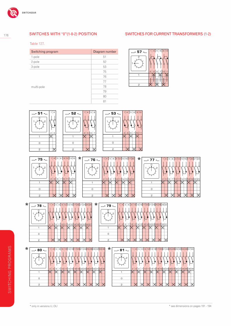
switchesforcurrenttransformers(1-2)
57 174
switcheswithout“0”(1-2)position
1-pole 54
175
2-pole 55
3-pole 56
multi-pole
69
70
71
72
73
74
62
multipositionswitcheswith“0”(0-1-2...)position
1-pole
3-position 107
1764-position 108
5-position 109
6-position 110
SWITCHING PROGRAMS
Switchingprogram diagramnumber page
multipositionswitcheswith“0”(0-1-2...)position
1-pole
7-position 111
176
8-position 112
9-position 113
10-position 114
11-position 115
12-position 116
2-pole
3-position 123
177
4-position 124
5-position 125
6-position 126
7-position 127
8-position 128
9-position 129
10-position 130
11-position 131
12-position 132
3-pole
3-position 135
178
4-position 136
5-position 137
6-position 138
7-position 139
8-position 140
multi-pole
3-position 145
178
4-position 146
5-position 147
6-position 148
3-position 151
4-position 152
5-position 153
179
3-position 156
4-position 157
5-position 158
3-position 160
4-position 161
3-position 163
4-position 164
multipositionswitcheswithout“0”position
1-pole
3-position 82
180
4-position 83
5-position 84
6-position 85
7-position 101
8-position 102
9-position 103
10-position 104
11-position 105
12-position 106
SW
ITC
HIN
G P
RO
GR
AM
S
ENERGY SAFELY SWITCHED
169
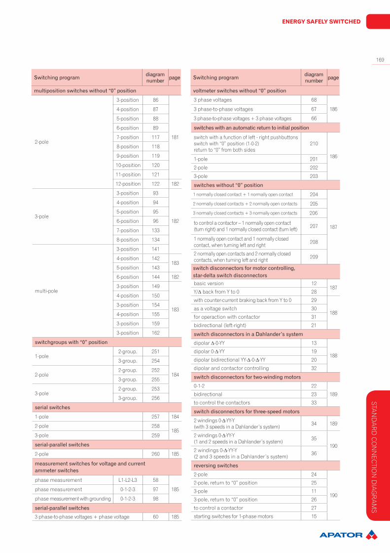
2-pole
3-position 86
181
4-position 87
5-position 88
6-position 89
7-position 117
8-position 118
9-position 119
10-position 120
11-position 121
12-position 122 182
3-pole
3-position 93
182
4-position 94
5-position 95
6-position 96
7-position 133
8-position 134
multi-pole
3-position 141
4-position 142183
5-position 143
6-position 144 182
3-position 149
183
4-position 150
3-position 154
4-position 155
3-position 159
3-position 162
switchgroupswith“0”position
1-pole2-group. 251
184
3-group. 254
2-pole2-group. 252
3-group. 255
3-pole2-group. 253
3-group. 256
serialswitches
1-pole 257 184
2-pole 258185
3-pole 259
serial-parallelswitches
2-pole 260 185
measurementswitchesforvoltageandcurrentammeterswitches
phase measurement L1-L2-L3 58
185phase measurement 0-1-2-3 97
phase measurement with grounding 0-1-2-3 98
serial-parallelswitches
3 phase-to-phase voltages + phase voltage 60 185
Switchingprogram diagramnumber page
multipositionswitcheswithout“0”position
3 phase voltages 68
1863 phase-to-phase voltages 67
3 phase-to-phase voltages + 3 phase voltages 66
switcheswithanautomaticreturntoinitialposition
switch with a function of left - right pushbuttonsswitch with “0” position (1-0-2)return to “0” from both sides
210
1861-pole 201
2-pole 202
3-pole 203
switcheswithout“0”position
1 normally closed contact + 1 normally open contact 204
187
2 normally closed contacts + 2 normally open contacts 205
3 normally closed contacts + 3 normally open contacts 206
to control a contactor – 1 normally open contact (turn right) and 1 normally closed contact (turn left) 207
1 normally open contact and 1 normally closed contact, when turning left and right 208
2 normally open contacts and 2 normally closed contacts, when turning left and right 209
switchdisconnectorsformotorcontrolling,star-deltaswitchdisconnectorsbasic version 12
187Y/∆ back from Y to 0 28
with counter-current braking back from Y to 0 29
188as a voltage switch 30
for operaction with contactor 31
bidirectional (left-right) 21
switchdisconnectorsinaDahlander’ssystem
dipolar ∆-0-YY 13
188dipolar 0-∆-YY 19
dipolar bidirectional YY-∆-0-∆-YY 20
dipolar and contactor controlling 32
switchdisconnectorsfortwo-windingmotors
0-1-2 22
189bidirectional 23
to control the contactors 33
switchdisconnectorsforthree-speedmotors
2 windings 0-∆-YY-Y (with 3 speeds in a Dahlander’s system) 34 189
2 windings 0-∆-YY-Y (1 and 2 speeds in a Dahlander’s system) 35
1902 windings 0-∆-YY-Y (2 and 3 speeds in a Dahlander’s system) 36
reversingswitches
2-pole 24
190
2-pole, return to “0” position 25
3-pole 11
3-pole, return to “0” position 26
to control a contactor 27
starting switches for 1-phase motors 15
Switchingprogram diagramnumber page
voltmeterswitcheswithout“0”position
STAN
DA
RD
CO
NN
ECTIO
N D
IAG
RA
MS

SWITCHGEAR
170
4G25 - 10 - U S5 R112
NOTES:1. every order on devices for rated current 100A requires arrangements with the manufacturer related to the technical details and delivery date.2. devices in PK housings can be made only for those switching programs which require not more than four segments (protection class IP 55/IP 65). EXPRES SERVICE 24 h or 48 h - There is the ability to perform cam switches in 24 or 48 h (additional fee)
STANDARD CONNECTION DIAGRAMS
version:U – switch to be built-inOU – switch to be mounted in a housingPK – switch in a plastic case
AN ORDER EXAMPLE
switch type determined according to the rated current, selection inaccordance with table 118
diagram number specifiedin the switching program
special version, its symbol can be added to the description of type
knob and handle version and colour according to table 120
STA
ND
AR
D C
ON
NEC
TIO
N D
IAG
RA
MS
Diagramnumber Numberofpoles
Ratedswitchingcurrent
Ratedvoltage
Numberofpacks
SymbolArticleNo. Handle
ProtectiondegreeIPfromthefront
Maximumconductorcross-section[mm2]
Installation
Switchdisconnectorwith“0”(0-1)position
1 10 690 1 4G10-90-U63-840390-011 R014 IP40 2 x 2,5
to b
e m
ount
ed
behi
nd th
e pa
nel
1 16 690 1 4G16-90-U63-840390-021 R114 IP40 2 x 4
1 25 690 1 4G25-90-U63-840390-031 R114 IP40 2 x 6
1 10 690 1 4G10-90-PK63-840392-011 R014 IP55 2 x 2,5
in a
hou
sing1 25 690 1 4G10-90-PK IP65
63-840392-111 R114 IP65 2 x 6
1 16 690 1 4G16-90-PK63-840392-021 R114 IP55 2 x 4
1 25 690 1 4G25-90-PK63-840392-031 R114 IP55 2 x 6
2 10 690 1 4G10-91-U63-840393-011 R014 IP40 2 x 2,5
to b
e m
ount
ed
behi
nd th
e pa
nel
2 16 690 1 4G16-91-U63-840393-021 R114 IP40 2 x 4
2 10 690 1 4G10-91-PK63-840395-011 R014 IP55 2 x 2,5
in a
hou
sing2 25 690 1 4G10-91-PK IP65
63-840395-111 R114 IP65 2 x 6
2 16 690 1 4G16-91-PK63-840395-021 R114 IP55 2 x 4
2 25 690 1 4G25-91-PK63-840395-031 R114 IP55 2 x 6
* see dimensions on pages 191 - 194

ENERGY SAFELY SWITCHED
171
STAN
DA
RD
CO
NN
ECTIO
N D
IAG
RA
MS
4 10 690 2 4G10-92-U63-840396-011 R014 IP40 2 x 2,5
to b
e m
ount
ed
behi
nd th
e pa
nel
4 16 690 2 4G16-92-U63-840396-021 R114 IP40 2 x 4
4 25 690 2 4G25-92-U63-840396-031 R114 IP40 2 x 6
4 40 690 2 4G40-92-U63-840396-041 R214 IP40 2 x 10
in a
hou
sing
4 63 690 2 4G63-92-U63-840396-051 R214 IP40 2 x 10
4 80 690 2 4G80-92-U63-840396-061 R214 IP40 25
4 10 690 2 4G10-92-PK63-840398-011 R014 IP55 2 x 2,5
4 10 690 2 4G10-92-PK IP6563-840398-111 R014 IP65 2 x 2,5
4 16 690 2 4G16-92-PK63-840398-021 R114 IP55 2 x 4
4 25 690 2 4G25-92-PK63-840398-031 R114 IP55 2 x 6
4 40 690 2 4G40-92-PK63-840398-041 R214 IP55 2 x 10
4 63 690 2 4G63-92-PK63-840398-051 R214 IP55 2 x 10
4 80 690 2 4G80-92-PK63-840398-061 R214 IP55 25
Diagramnumber Numberofpoles
Ratedswitchingcurrent
Ratedvoltage
Numberofpacks
SymbolArticleNo. Handle
ProtectiondegreeIPfromthefront
Maximumconductorcross-section[mm2]
Installation
Switchdisconnectorwith“0”(0-1)position
3 10 690 2 4G10-10-U63-840304-011 R014 IP40 2 x 2,5
to b
e m
ount
ed
behi
nd th
e pa
nel
3 16 690 2 4G16-10-U63-840304-021 R114 IP40 2 x 4
3 25 690 2 4G25-10-U63-840304-031 R114 IP40 2 x 6
3 40 690 2 4G40-10-U63-840304-041 R214 IP40 2 x 10
3 63 690 2 4G63-10-U63-840304-051 R214 IP40 2 x 10
3 80 690 2 4G80-10-U63-840304-061 R214 IP40 25
3 10 690 2 4G10-10-PK63-840306-011 R014 IP55 2 x 2,5
in a
hou
sing
3 10 690 2 4G10-10-PK IP6563-840306-111 R014 IP65 2 x 2,5
3 16 690 2 4G16-10-PK63-840306-021 R114 IP55 2 x 4
3 25 690 2 4G25-10-PK63-840306-031 R114 IP55 2 x 6
3 40 690 2 4G40-10-PK63-840306-041 R214 IP55 2 x 10
3 63 690 2 4G63-10-PK63-840306-051 R214 IP55 2 x 10
3 80 690 2 4G80-10-PK63-840306-061 R214 IP55 25
* see dimensions on pages 191 - 194

SWITCHGEAR
172
STA
ND
AR
D C
ON
NEC
TIO
N D
IAG
RA
MS
Diagramnumber Numberofpoles
Ratedswitchingcurrent
Ratedvoltage
Numberofpacks
SymbolArticleNo. Handle
ProtectiondegreeIPfromthefront
Maximumconductorcross-section[mm2]
Installation
“mains-unit”switch(1-0-2)
1 10 690 1 4G10-51-U63-840338-011 R014 IP40 2 x 2,5
to be mounted behind
the panel
1 10 690 1 4G10-51-PK63-840340-011 R014 IP55 2 x 2,5
in a
hou
sing
1 10 690 1 4G10-51-PK IP6563-840340-111 R014 IP65 2 x 2,5
2 10 690 2 4G10-52-U63-840341-011 R014 IP40 2 x 2,5
to b
e m
ount
ed
behi
nd th
e pa
nel
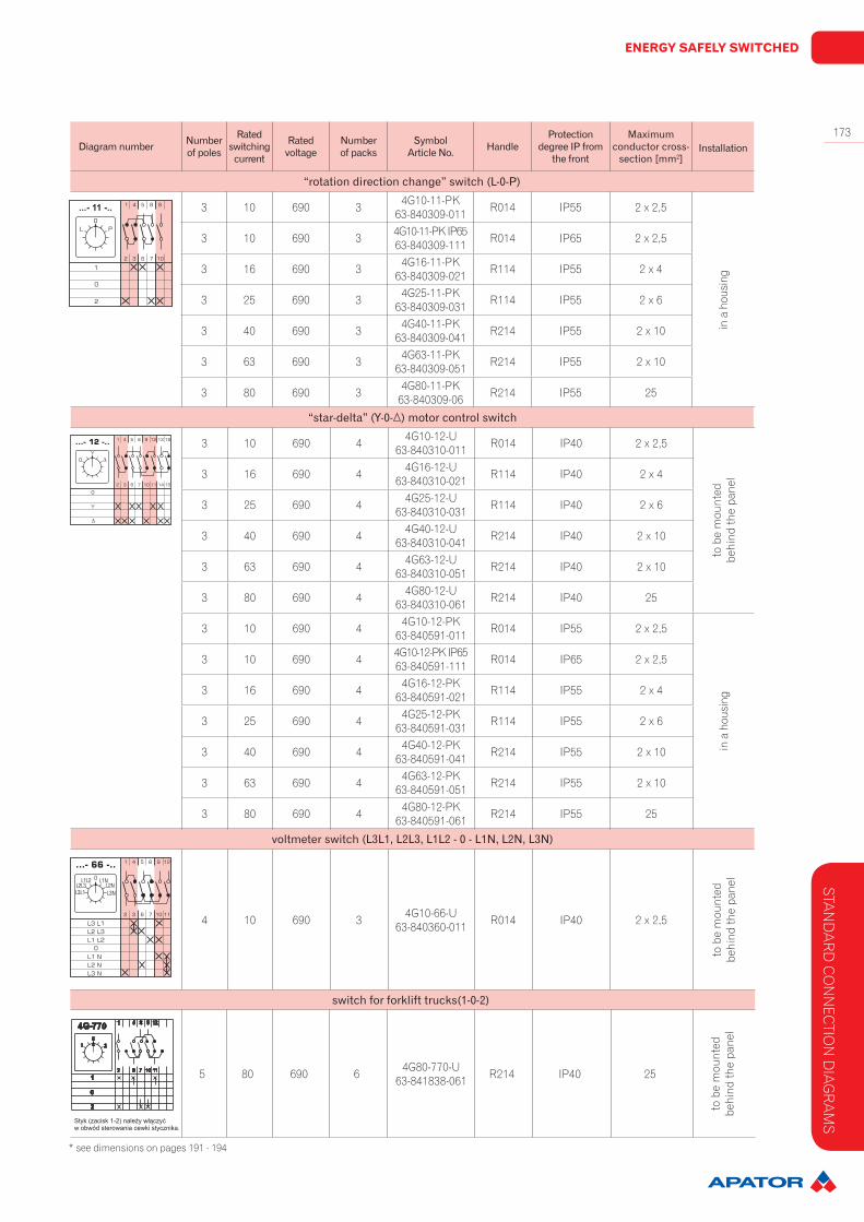
“rotationdirectionchange”switch(L-0-P)
3 10 690 3 4G10-11-U63-840307-011 R014 IP40 2 x 2,5
to b
e m
ount
ed
behi
nd th
e pa
nel
3 16 690 3 4G16-11-U63-840307-021 R114 IP40 2 x 4
3 25 690 3 4G25-11-U63-840307-031 R114 IP40 2 x 6
3 40 690 3 4G40-11-U63-840307-041 R214 IP40 2 x 10
3 63 690 3 4G63-11-U63-840307-051 R214 IP40 2 x 10
3 80 690 3 4G80-11-U63-840307-061 R214 IP40 25
3 10 690 3 4G10-53-U63-840343-011 R014 IP40 2 x 2,5
to b
e m
ount
ed
behi
nd th
e pa
nel
3 16 690 3 4G16-53-U63-840343-021 R114 IP40 2 x 4
3 25 690 3 4G25-53-U63-840343-031 R114 IP40 2 x 6
3 40 690 3 4G40-53-U63-840343-041 R214 IP40 2 x 10
3 63 690 3 4G63-53-U63-840343-051 R214 IP40 2 x 10
3 80 690 3 4G80-53-U63-840343-061 R214 IP40 25
3 10 690 3 4G10-53-PK63-840345-011 R014 IP55 2 x 2,5
in a
hou
sing
3 10 690 3 4G10-53-PK IP6563-840345-111 R014 IP65 2 x 2,5
3 16 690 3 4G16-53-PK63-840345-021 R114 IP55 2 x 4
3 25 690 3 4G25-53-PK63-840345-031 R114 IP55 2 x 6
3 40 690 3 4G40-53-PK63-840345-041 R214 IP55 2 x 10
3 63 690 3 4G63-53-PK63-840345-051 R214 IP55 2 x 10
3 80 690 3 4G80-53-PK63-840345-061 R214 IP55 25
* see dimensions on pages 191 - 194
ENERGY SAFELY SWITCHED
173
STAN
DA
RD
CO
NN
ECTIO
N D
IAG
RA
MS
voltmeterswitch(L3L1,L2L3,L1L2-0-L1N,L2N,L3N)
4 10 690 3 4G10-66-U63-840360-011 R014 IP40 2 x 2,5
to b
e m
ount
ed
behi
nd th
e pa
nel
switchforforklifttrucks(1-0-2)
5 80 690 6 4G80-770-U63-841838-061 R214 IP40 25
to b
e m
ount
ed
behi
nd th
e pa
nel
* see dimensions on pages 191 - 194
Diagramnumber Numberofpoles
Ratedswitchingcurrent
Ratedvoltage
Numberofpacks
SymbolArticleNo. Handle
ProtectiondegreeIPfromthefront
Maximumconductorcross-section[mm2]
Installation
“rotationdirectionchange”switch(L-0-P)
3 10 690 3 4G10-11-PK63-840309-011 R014 IP55 2 x 2,5
in a
hou
sing
3 10 690 3 4G10-11-PK IP6563-840309-111 R014 IP65 2 x 2,5
3 16 690 3 4G16-11-PK63-840309-021 R114 IP55 2 x 4
3 25 690 3 4G25-11-PK63-840309-031 R114 IP55 2 x 6
3 40 690 3 4G40-11-PK63-840309-041 R214 IP55 2 x 10
3 63 690 3 4G63-11-PK63-840309-051 R214 IP55 2 x 10
3 80 690 3 4G80-11-PK63-840309-06 R214 IP55 25
“star-delta”(Y-0- )motorcontrolswitch
3 10 690 4 4G10-12-U63-840310-011 R014 IP40 2 x 2,5
to b
e m
ount
ed
behi
nd th
e pa
nel3 16 690 4 4G16-12-U
63-840310-021 R114 IP40 2 x 4
3 25 690 4 4G25-12-U63-840310-031 R114 IP40 2 x 6
3 40 690 4 4G40-12-U63-840310-041 R214 IP40 2 x 10
3 63 690 4 4G63-12-U63-840310-051 R214 IP40 2 x 10
3 80 690 4 4G80-12-U63-840310-061 R214 IP40 25
3 10 690 4 4G10-12-PK63-840591-011 R014 IP55 2 x 2,5
in a
hou
sing
3 10 690 4 4G10-12-PK IP6563-840591-111 R014 IP65 2 x 2,5
3 16 690 4 4G16-12-PK63-840591-021 R114 IP55 2 x 4
3 25 690 4 4G25-12-PK63-840591-031 R114 IP55 2 x 6
3 40 690 4 4G40-12-PK63-840591-041 R214 IP55 2 x 10
3 63 690 4 4G63-12-PK63-840591-051 R214 IP55 2 x 10
3 80 690 4 4G80-12-PK63-840591-061 R214 IP55 25
SWITCHGEAR
174
STA
ND
AR
D C
ON
NEC
TIO
N D
IAG
RA
MS
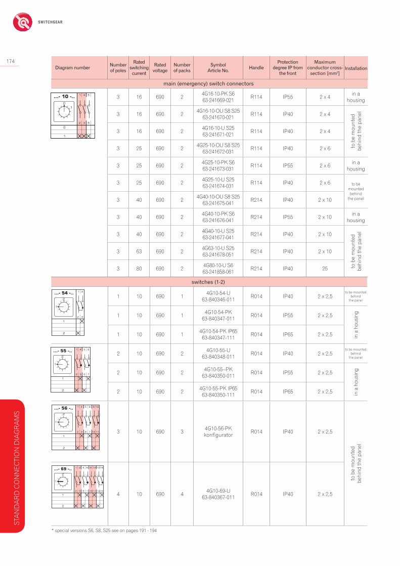
switches(1-2)
1 10 690 1 4G10-54-U63-840346-011 R014 IP40 2 x 2,5
to be mounted behind
the panel
1 10 690 1 4G10-54-PK63-840347-011 R014 IP55 2 x 2,5
in a
hou
sing
1 10 690 1 4G10-54-PK IP6563-840347-111 R014 IP65 2 x 2,5
2 10 690 2 4G10-55-U63-840348-011 R014 IP40 2 x 2,5
to be mounted behind
the panel
2 10 690 2 4G10-55--PK63-840350-011 R014 IP55 2 x 2,5
in a
hou
sing
2 10 690 2 4G10-55-PK IP6563-840350-111 R014 IP65 2 x 2,5
3 10 690 3 4G10-56-PKkonfigurator R014 IP40 2 x 2,5
to b
e m
ount
ed
behi
nd th
e pa
nel
4 10 690 4 4G10-69-U63-840367-011 R014 IP40 2 x 2,5
main(emergency)switchconnectors
3 16 690 2 4G16-10-PK S663-241669-021 R114 IP55 2 x 4 in a
housing
3 16 690 2 4G16-10-OU S8 S2563-241670-021 R114 IP40 2 x 4
to b
e m
ount
ed
behi
nd th
e pa
nel
3 16 690 2 4G16-10-U S2563-241671-021 R114 IP40 2 x 4
3 25 690 2 4G25-10-OU S8 S2563-241672-031 R114 IP40 2 x 6
3 25 690 2 4G25-10-PK S663-241673-031 R114 IP55 2 x 6 in a
housing
3 25 690 2 4G25-10-U S2563-241674-031 R114 IP40 2 x 6 to be
mounted behind
the panel3 40 690 2 4G40-10-OU S8 S2563-241675-041 R214 IP40 2 x 10
3 40 690 2 4G40-10-PK S663-241676-041 R214 IP55 2 x 10 in a
housing
3 40 690 2 4G40-10-U S2563-241677-041 R214 IP40 2 x 10
to b
e m
ount
ed
behi
nd th
e pa
nel
3 63 690 2 4G63-10-U S2563-241678-051 R214 IP40 2 x 10
3 80 690 2 4G80-10-U S663-241858-061 R214 IP40 25
* special versions S6, S8, S25 see on pages 191 - 194
Diagramnumber Numberofpoles
Ratedswitchingcurrent
Ratedvoltage
Numberofpacks
SymbolArticleNo. Handle
ProtectiondegreeIPfromthefront
Maximumconductorcross-section[mm2]
Installation

ENERGY SAFELY SWITCHED
175
Switchingprogram Diagramnumber1-pole 90
2-pole 91
3-pole 10
multi-pole
92
99
100
528
659
SWITCHDISCONNECTORWITH“0”(0-1)POSITION
Switchingprogram Diagramnumberwith 30º contact lead 30° 1-pole 270
with 30º contact lead 30° 2-pole 271
with 30º contact lead 30° 3-pole 63
with 30º contact lead on three contacts and 60º on one contact 4-pole 272
with 30º contact lead on three contacts and 60º on two contacts 5-pole 273
with 30º contact lead 30° 6-pole 274
SWITCHING PROGRAMS
Table 125.
SWITCHDISCONNECTORSWITHQUICK-CONNECTINGCONTACTS(0-1)
Table 126.
SW
ITCH
ING
PR
OG
RA
MS
* see dimensions on pages 191 - 194
SWITCHGEAR
176 SWITCHESFORCURRENTTRANSFORMERS(1-2)
Switchingprogram Diagramnumber
1-pole 51
2-pole 52
3-pole 53
multi-pole
75
76
77
78
79
80
81
SWITCHESWITH“0”(1-0-2)POSITION
Table 127.
* only in versions U, OU * see dimensions on pages 191 - 194
* *
* *
* *
SW
ITC
HIN
G P
RO
GR
AM
S

ENERGY SAFELY SWITCHED
177
Switchingprogram Diagramnumber1-pole 54
2-pole 55
3-pole 56
multi-pole
69
70
71
72
73
74
62
* only in versions U, OU
SWITCHESWITHOUT“0”(1-2)POSITION
Table 128.
* *
**
* * SW
ITCH
ING
PR
OG
RA
MS
*see dimensions on pages 191 - 194
SWITCHGEAR
178
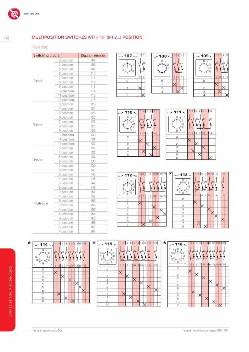
Switchingprogram Diagramnumber
1-pole
3-position 1074-position 1085-position 1096-position 1107-position 1118-position 1129-position 11310-position 11411-position 11512-position 116
2-pole
3-position 1234-position 1245-position 1256-position 1267-position 1278-position 1289-position 12910-position 13011-position 13112-position 132
3-pole
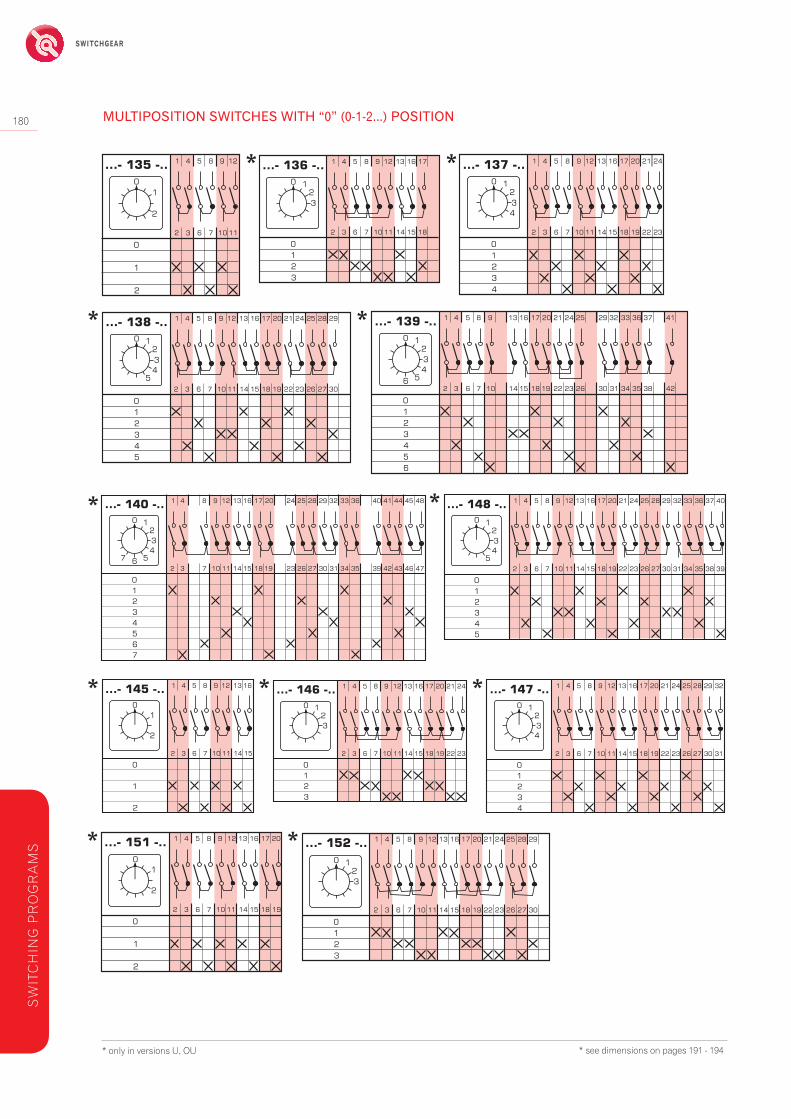
3-position 1354-position 1365-position 1376-position 1387-position 1398-position 140
multi-pole
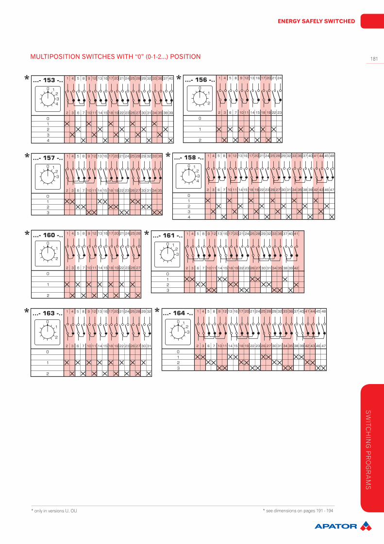
3-position 1454-position 1465-position 1476-position 1483-position 1514-position 1525-position 1533-position 1564-position 1575-position 1583-position 1604-position 1613-position 1634-position 164
MULTIPOSITIONSWITCHESWITH“0”(0-1-2...)POSITION
Table 129.
* only in versions U, OU
*
* * *
SW
ITC
HIN
G P
RO
GR
AM
S
* see dimensions on pages 191 - 194

ENERGY SAFELY SWITCHED
179MULTIPOSITIONSWITCHESWITH“0”(0-1-2...)POSITION
* only in versions U, OU
*
* *
**
* *
SW
ITCH
ING
PR
OG
RA
MS
* see dimensions on pages 191 - 194
SWITCHGEAR
180
* only in versions U, OU
MULTIPOSITIONSWITCHESWITH“0”(0-1-2...)POSITION
* *
**
* *
***
* *
SW
ITC
HIN
G P
RO
GR
AM
S
* see dimensions on pages 191 - 194
ENERGY SAFELY SWITCHED
181
* only in versions U, OU
MULTIPOSITIONSWITCHESWITH“0”(0-1-2...)POSITION
* *
**
* *
**
SW
ITCH
ING
PR
OG
RA
MS
* see dimensions on pages 191 - 194

SWITCHGEAR
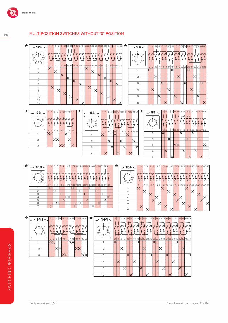
182 MULTIPOSITIONSWITCHESWITHOUT“0”POSITION
Switchingprogram Diagramnumber
1-pole
3-position 824-position 835-position 846-position 857-position 1018-position 1029-position 10310-position 10411-position 10512-position 106
2-pole
3-position 864-position 875-position 886-position 897-position 1178-position 1189-position 11910-position 12011-position 12112-position 122
3-pole
3-position 934-position 945-position 956-position 967-position 1338-position 134
multi-pole
3-position 1414-position 1425-position 1436-position 1443-position 1494-position 1503-position 1544-position 1553-position 1593-position 162
* only in versions U, OU
Table 130.
*
***
SW
ITC
HIN
G P
RO
GR
AM
S
* see dimensions on pages 191 - 194

ENERGY SAFELY SWITCHED
183
* only in versions U, OU
MULTIPOSITIONSWITCHESWITHOUT“0”POSITION
*
* *
**
* *
SW
ITCH
ING
PR
OG
RA
MS
* see dimensions on pages 191 - 194
SWITCHGEAR
184
* only in versions U, OU
MULTIPOSITIONSWITCHESWITHOUT“0”POSITION
* *
* * *
* *
* *
* see dimensions on pages 191 - 194
SW
ITC
HIN
G P
RO
GR
AM
S

ENERGY SAFELY SWITCHED
185
* only in versions U, OU
MULTIPOSITIONSWITCHESWITHOUT“0”POSITION
* *
* *
**
**
* see dimensions on pages 191 - 194
SW
ITCH
ING
PR
OG
RA
MS

SWITCHGEAR
186
Switchingprogram Diagramnumber
1-pole2-group 251
3-group 254
2-pole2-group 252
3-group 255
3-pole2-group 253
3-group 256
* only in versions U, OU
SWITCHGROUPSWITH“0”POSITION
Table 131.
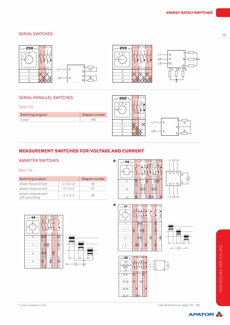
Switchingprogram Diagramnumber1-pole 257
2-pole 258
3-pole 259
Table 132.
SERIALSWITCHES
*
* see dimensions on pages 191 - 194
SW
ITC
HIN
G P
RO
GR
AM
S
ENERGY SAFELY SWITCHED
187
Switchingprogram Diagramnumberphase measurement L1–L2–L3 58
phase measurement 0–1–2–3 97
phase measurementwith grounding 0–1–2–3 98
SERIAL-PARALLELSWITCHES
Switchingprogram Diagramnumber2-pole 260
SERIALSWITCHES
* only in versions U, OU
Table 133.
AMMETERSWITCHES
Table 134.
MEASUREMENT SWITCHES FOR VOLTAGE AND CURRENT
* see dimensions on pages 191 - 194
SW
ITCH
ING
PR
OG
RA
MS
*
*
SWITCHGEAR
188
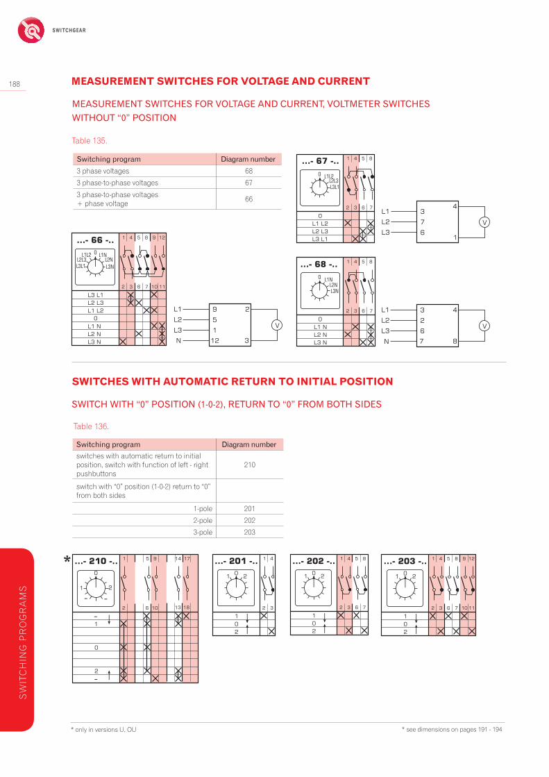
Switchingprogram Diagramnumber3 phase voltages 68
3 phase-to-phase voltages 67
3 phase-to-phase voltages + phase voltage 66
Switchingprogram Diagramnumberswitches with automatic return to initial position, switch with function of left - right pushbuttons
210
switch with “0” position (1-0-2) return to “0” from both sides
1-pole 201
2-pole 202
3-pole 203
SWITCHES WITH AUTOMATIC RETURN TO INITIAL POSITION
MEASUREMENT SWITCHES FOR VOLTAGE AND CURRENT
Table 135.
* only in versions U, OU
Table 136.
*
MEASUREMENTSWITCHESFORVOLTAGEANDCURRENT,VOLTMETERSWITCHESWITHOUT“0”POSITION
SWITCHWITH“0”POSITION(1-0-2),RETURNTO“0”FROMBOTHSIDES
* see dimensions on pages 191 - 194
SW
ITC
HIN
G P
RO
GR
AM
S

ENERGY SAFELY SWITCHED
189
Switchingprogram Diagramnumber
1 normally closed contact + 1 normally open contact 204
2 normally closed contacts + 2 normally open contacts 205
3 normally closed contacts + 3 normally open contacts 206
to control a contactor – 1 normally open contact (turn right) and 1 normally closed contact (turn left)
207
1 normally open contact and 1 normally closed contact, when turning left and right 208
2 normally open contacts and 2 normally closed contacts, when turning left and right 209
Switchingprogram Diagramnumberbasic version 12
Y/∆ back from Y to 0 28
with counter-current braking back from Y to 0 29
as a voltage switch 30
for operaction with contactor 31
bidirectional (left-right) 21
SWITCH DISCONNECTORS FOR MOTOR CONTROLLING
SWITCHES WITH AUTOMATIC RETURN TO INITIAL POSITION
Table 137.
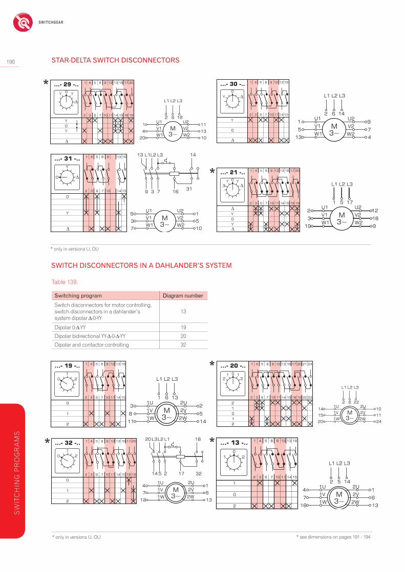
STAR-DELTASWITCHDISCONNECTORS
Table 138.
SWITCHESWITHOUT“0”(0-2)POSITION
* see dimensions on pages 191 - 194
SW
ITCH
ING
PR
OG
RA
MS
SWITCHGEAR
190
SWITCHDISCONNECTORSINADAHLANDER’SSYSTEM
Switchingprogram Diagramnumber
Switch disconnectors for motor controlling, switch disconnectors in a dahlander’s system dipolar ∆-0-YY
13
Dipolar 0-∆-YY 19
Dipolar bidirectional YY-∆-0-∆-YY 20
Dipolar and contactor controlling 32
* only in versions U, OU
STAR-DELTASWITCHDISCONNECTORS
* only in versions U, OU
Table 139.
*
*
**
* see dimensions on pages 191 - 194
SW
ITC
HIN
G P
RO
GR
AM
S
*

ENERGY SAFELY SWITCHED
191
Switchingprogram Diagramnumber0-1-2 22
bidirectional 23
to control the contactors 33
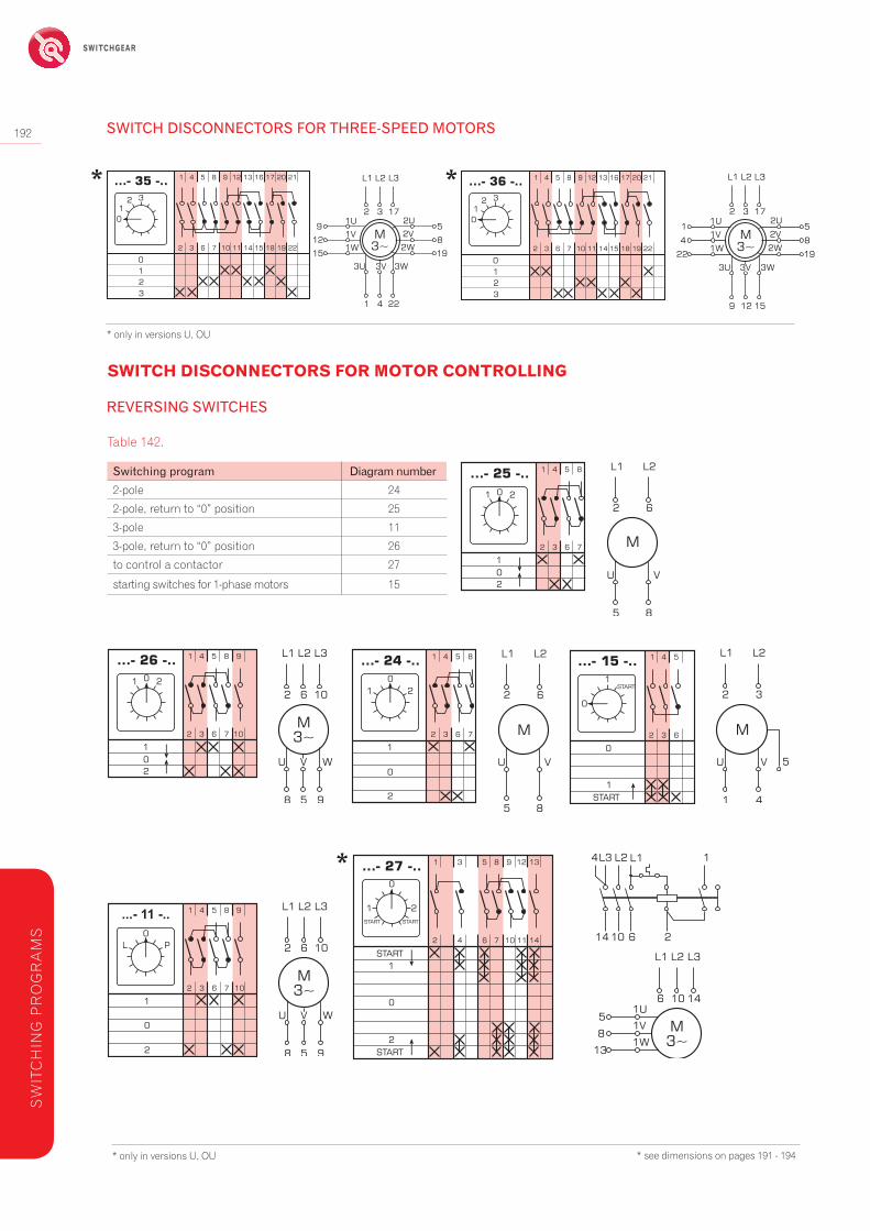
SWITCHDISCONNECTORSFORTHREE-SPEEDMOTORS
Switchingprogram Diagramnumber
2 windings 0-∆-Y-YY (with 3 speeds in a Dahlander’s system) 34
2 windings 0-∆-YY-Y (1 and 2 speeds in a Dahlander’s system) 35
2 windings 0-Y-∆-YY (2 and 3 speeds in a Dahlander’s system) 36
* only in versions U, OU
SWITCH DISCONNECTORS FOR MOTOR CONTROLLING
Table 140.
* only in versions U, OU * see dimensions on pages 167-170
Table 141.
SWITCHDISCONNECTORSFORTWO-WINDINGMOTORS
*
*
* see dimensions on pages 191 - 194
SW
ITCH
ING
PR
OG
RA
MS
SWITCHGEAR
192
Switchingprogram Diagramnumber2-pole 24
2-pole, return to “0” position 25
3-pole 11
3-pole, return to “0” position 26
to control a contactor 27
starting switches for 1-phase motors 15
* only in versions U, OU
SWITCHDISCONNECTORSFORTHREE-SPEEDMOTORS
* only in versions U, OU
SWITCH DISCONNECTORS FOR MOTOR CONTROLLING
Table 142.
REVERSINGSWITCHES
* *
*
* see dimensions on pages 191 - 194
SW
ITC
HIN
G P
RO
GR
AM
S
ENERGY SAFELY SWITCHED
193
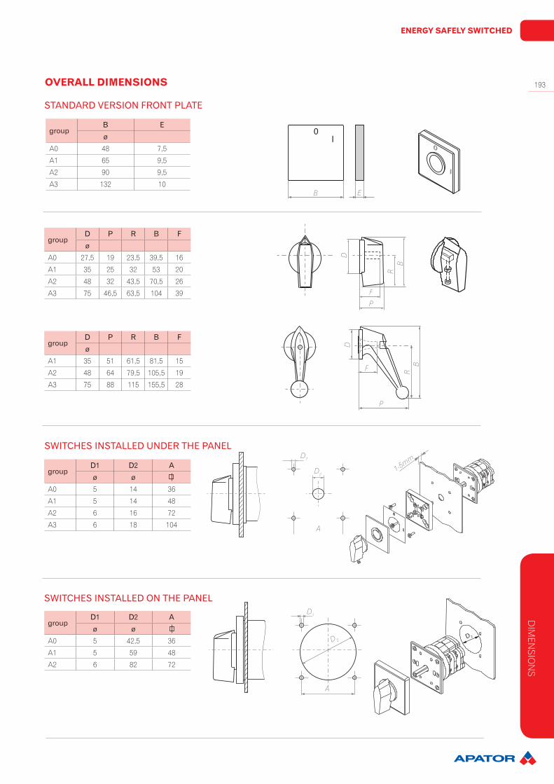
groupB Eø
A0 48 7,5
A1 65 9,5
A2 90 9,5
A3 132 10
groupD1 D2 Aø ø
A0 5 14 36
A1 5 14 48
A2 6 16 72
A3 6 18 104
groupD1 D2 Aø ø
A0 5 42,5 36
A1 5 59 48
A2 6 82 72
groupD P R B Fø
A0 27,5 19 23,5 39,5 16
A1 35 25 32 53 20
A2 48 32 43,5 70,5 26
A3 75 46,5 63,5 104 39
groupD P R B Fø
A1 35 51 61,5 81,5 15
A2 48 64 79,5 105,5 19
A3 75 88 115 155,5 28
OVERALL DIMENSIONS
STANDARDVERSIONFRONTPLATE
SWITCHESINSTALLEDUNDERTHEPANEL
SWITCHESINSTALLEDONTHEPANEL
0
I
B E
P
F
BR
DD
F
PB
R
D1
D2
A
1-5mm
D 2
D1
D 2
A
DIM
ENSIO
NS

SWITCHGEAR
194
group switchtypeL(dependingonthenumberofswitchingelements)
1 2 3 4 5 6 7 8 9 10 11 12A0 4G 10 33 42,5 52 61,5 71 81 90,5 100 109,5 119 129 138,5
A14G 16 46,5 60 73,5 87,5 101 114,5 128,5 143 156 169,5 183 196,5
4G 25 46,5 60 73,5 87,5 101 114,5 128,5 143 156 169,5 183 196,5
A24G 40 56,5 74,5 92,5 110,5 128,5 146,5 164,5 182,5 200,5 218,5 236,5 254,5
4G 63, 80 56,5 74,5 92,5 110,5 128,5 146,5 164,5 182,5 200,5 218,5 236,5 254,5
A3
4G 100 77 107 136 166 196 226 284 314 343 373 402 432
4G 200 77 107 136 166 196 226 284 314 343 373 402 432
4G 400 – 107 – 166 – 226 – 314 – 373 – 432
4G 630 – – 136 – – 226 – – 343 – – 432
4G 800 – 107 – 166 – 226 – 314 – 373 – 432
4G 1200 – – 136 – – 226 – – 343 – – 432
group switchtypeD1 D2 A B C E F G H I Kø ø
A0 4G 10 38 4,3 36 48 6 9,6 22 4 – – –
A14G 16 57 4,3 48 65 6 13,5 26 3 – – –
4G 25 57 4,3 48 65 6 13,5 26 3 – – –
A24G 40 80 5,3 72 90 8 18 31 5 – – –
4G 63, 80 80 5,3 72 90 8 18 31 5 – – –
A3
4G 100 120 5,3 104 132 10 29 37,5 6 – – –
4G 200 120 5,3 104 132 10 29 37,5 6 145 20 10,5
4G 400 120 5,3 104 132 10 29 37,5 6 170 45 13
4G 630 120 5,3 104 132 10 29 37,5 6 190 74 17,5
4G 800 120 5,3 104 132 10 29 37,5 6 260 50 17,5
4G 1200 120 5,3 104 132 10 29 37,5 6 260 80 17,5
protection degree IP40 (from the front plate side), IP55 in a special version – S1
OVERALL DIMENSIONS
USWITCHESTOBEBUILT-IN
A BH D1
K
LI
E
G
F
C
D2
DIM
ENSI
ON
S
ENERGY SAFELY SWITCHED
195
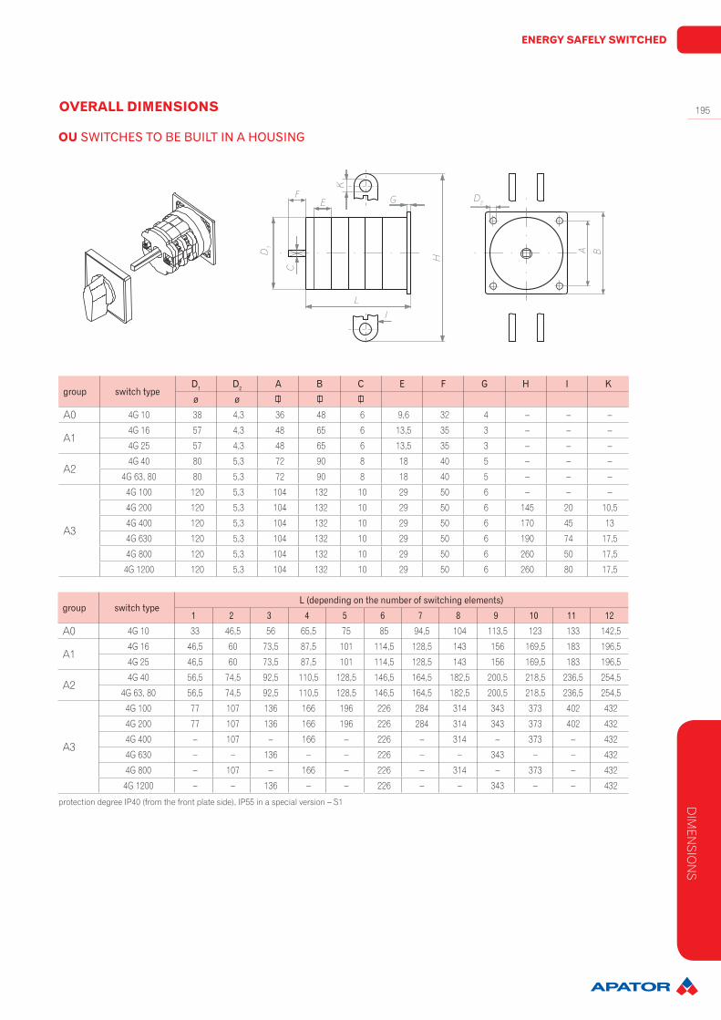
group switchtypeL(dependingonthenumberofswitchingelements)
1 2 3 4 5 6 7 8 9 10 11 12
A0 4G 10 33 46,5 56 65,5 75 85 94,5 104 113,5 123 133 142,5
A14G 16 46,5 60 73,5 87,5 101 114,5 128,5 143 156 169,5 183 196,5
4G 25 46,5 60 73,5 87,5 101 114,5 128,5 143 156 169,5 183 196,5
A24G 40 56,5 74,5 92,5 110,5 128,5 146,5 164,5 182,5 200,5 218,5 236,5 254,5
4G 63, 80 56,5 74,5 92,5 110,5 128,5 146,5 164,5 182,5 200,5 218,5 236,5 254,5
A3
4G 100 77 107 136 166 196 226 284 314 343 373 402 432
4G 200 77 107 136 166 196 226 284 314 343 373 402 432
4G 400 – 107 – 166 – 226 – 314 – 373 – 432
4G 630 – – 136 – – 226 – – 343 – – 432
4G 800 – 107 – 166 – 226 – 314 – 373 – 432
4G 1200 – – 136 – – 226 – – 343 – – 432
group switchtypeD1 D2 A B C E F G H I Kø ø
A0 4G 10 38 4,3 36 48 6 9,6 32 4 – – –
A14G 16 57 4,3 48 65 6 13,5 35 3 – – –
4G 25 57 4,3 48 65 6 13,5 35 3 – – –
A24G 40 80 5,3 72 90 8 18 40 5 – – –
4G 63, 80 80 5,3 72 90 8 18 40 5 – – –
A3
4G 100 120 5,3 104 132 10 29 50 6 – – –
4G 200 120 5,3 104 132 10 29 50 6 145 20 10,5
4G 400 120 5,3 104 132 10 29 50 6 170 45 13
4G 630 120 5,3 104 132 10 29 50 6 190 74 17,5
4G 800 120 5,3 104 132 10 29 50 6 260 50 17,5
4G 1200 120 5,3 104 132 10 29 50 6 260 80 17,5
OVERALL DIMENSIONS
OU SWITCHESTOBEBUILTINAHOUSING
protection degree IP40 (from the front plate side), IP55 in a special version – S1
F
D1
E
K
CL
I
G
H
A B
D2
DIM
ENSIO
NS

SWITCHGEAR
196
group SwitchtypeD A1 A2 A3 B M N R Thread
PL(dependingonthenumberoftheswitchingelements)
ø 1 2 3 4A0 4G 10 4,3 55 38 54 64 13 25 19 11 55,5 55,5 75 75
A14G 16 4,3 75 75 75 85 19 34 25 16 77 77 104 104 4G 25 4,3 75 75 75 85 19 34 25 16 77 77 104 104
A24G 40 5,3 109 91 107 120 29 45 32 21 95 95 132 132
4G 63, 4G 80 5,3 109 91 107 120 29 45 32 21 95 95 132 132
INSTALLATION DIMENSIONS
PK SWITCHESINAPLASTICHOUSING
protection degree IP55 (standard)
N
M L R
A BP thread accordingto PN-70/E-02502
P thread
A3
A2
D
D
A3
A2
Installation holes’spacing
DIM
ENSI
ON
S
PK CAMSWITCHESINTHERMOPLASTICENCLOSURESWITHIP65DEGREEOFPROTECTION
Installation holes’spacing
A2
A1
D
thread
group SwitchtypeD A B A1 A2 M N P Thread L(dependingonthenumber
oftheswitchingelements)
ø 1or2 3or4
A0 4G 10 4,5 64 75 50 64 14 28 19 M20 60 81,5
N
A B
thread
ML P
ENERGY SAFELY SWITCHED
197
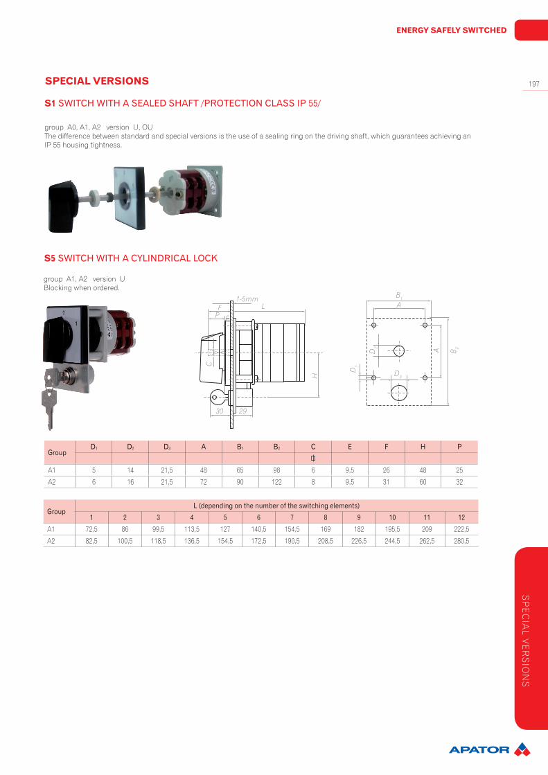
GroupD1 D2 D3 A B1 B2 C E F H P
A1 5 14 21,5 48 65 98 6 9,5 26 48 25
A2 6 16 21,5 72 90 122 8 9,5 31 60 32
SPECIAL VERSIONS
S1SWITCHWITHASEALEDSHAFT/PROTECTIONCLASSIP55/
group A0, A1, A2 version U, OUThe difference between standard and special versions is the use of a sealing ring on the driving shaft, which guarantees achieving an IP 55 housing tightness.
S5 SWITCHWITHACYLINDRICALLOCK
group A1, A2 version UBlocking when ordered.
GroupL(dependingonthenumberoftheswitchingelements)
1 2 3 4 5 6 7 8 9 10 11 12A1 72,5 86 99,5 113,5 127 140,5 154,5 169 182 195,5 209 222,5
A2 82,5 100,5 118,5 136,5 154,5 172,5 190,5 208,5 226,5 244,5 262,5 280,5
D1
D2
B1
A
A B 2
D3HL
EPF
C
1-5mm
30 29
SP
EC
IAL V
ER
SIO
NS
SWITCHGEAR
198
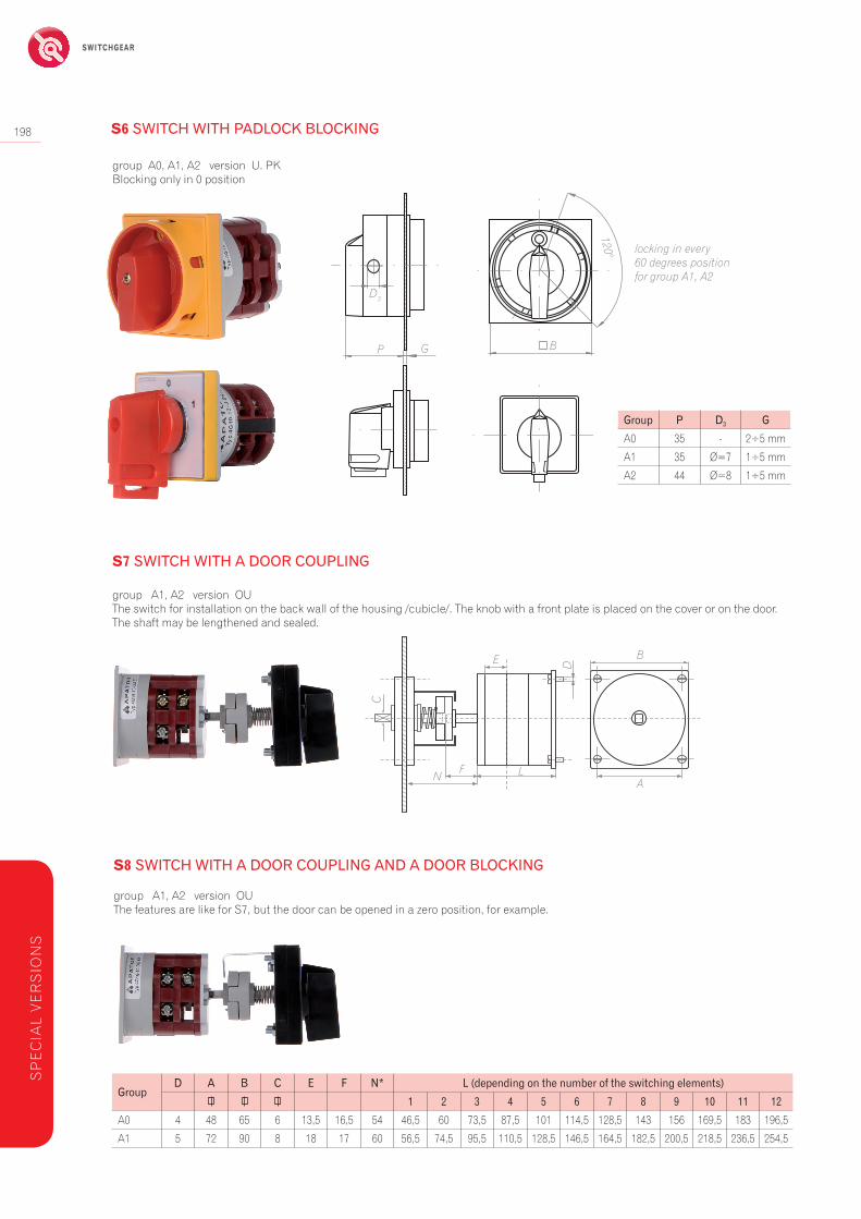
group A0, A1, A2 version U. PK Blocking only in 0 position
Group P D3 GA0 35 - 2÷5 mm
A1 35 Ø=7 1÷5 mm
A2 44 Ø=8 1÷5 mm
S6SWITCHWITHPADLOCKBLOCKING
S8 SWITCHWITHADOORCOUPLINGANDADOORBLOCKING
group A1, A2 version OU The features are like for S7, but the door can be opened in a zero position, for example.
GroupD A B C E F N* L(dependingonthenumberoftheswitchingelements)
1 2 3 4 5 6 7 8 9 10 11 12A0 4 48 65 6 13,5 16,5 54 46,5 60 73,5 87,5 101 114,5 128,5 143 156 169,5 183 196,5
A1 5 72 90 8 18 17 60 56,5 74,5 95,5 110,5 128,5 146,5 164,5 182,5 200,5 218,5 236,5 254,5
D3
P G B
120°
S7SWITCHWITHADOORCOUPLING
group A1, A2 version OUThe switch for installation on the back wall of the housing /cubicle/. The knob with a front plate is placed on the cover or on the door. The shaft may be lengthened and sealed.
NF L
E B
A
D
C
SP
EC
IAL
VE
RS
ION
S
locking in every 60 degrees position for group A1, A2
ENERGY SAFELY SWITCHED
199
GroupD A B C E F N* L(dependingonthenumberoftheswitchingelements)
1 2 3 4 5 6 7 8 9 10 11 12A0 4 48 65 6 13,5 16,5 54 46,5 60 73,5 87,5 101 114,5 128,5 143 156 169,5 183 196,5
A1 5 72 90 8 18 17 60 56,5 74,5 95,5 110,5 128,5 146,5 164,5 182,5 200,5 218,5 236,5 254,5
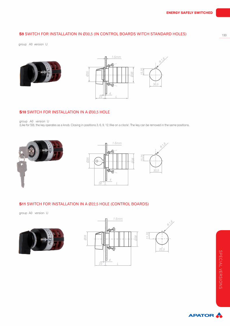
S9SWITCHFORINSTALLATIONINØ30,5(INCONTROLBOARDSWITCHSTANDARDHOLES)
group A0 version U
S10SWITCHFORINSTALLATIONINAØ30,5HOLE
group A0 version U(Like for S9), the key operates as a knob. Closing in positions 3, 6, 9, 12 /like on a clock/. The key can be removed in the same positions.
S11SWITCHFORINSTALLATIONINAØ22,5HOLE(CONTROLBOARDS)
group A0 version U
L
Ø35
1-5mm
234
Ø38 15
,25
30,5
R 1,6
L
Ø35
1-5mm
304
Ø38 15
,25
30,5
R 1,6
L
Ø28
1-5mm
234
Ø38 11
,25
22,5
R 1,6
SP
EC
IAL V
ER
SIO
NS
SWITCHGEAR
200
versionS9,S10,S11,S12
L(dependentonthenumberofswitchingelements)1 2 3 4 5 6 7 8 9 10 11 1247 56,5 66 75,5 85 95 104,5 114 123,5 133 143 152,5
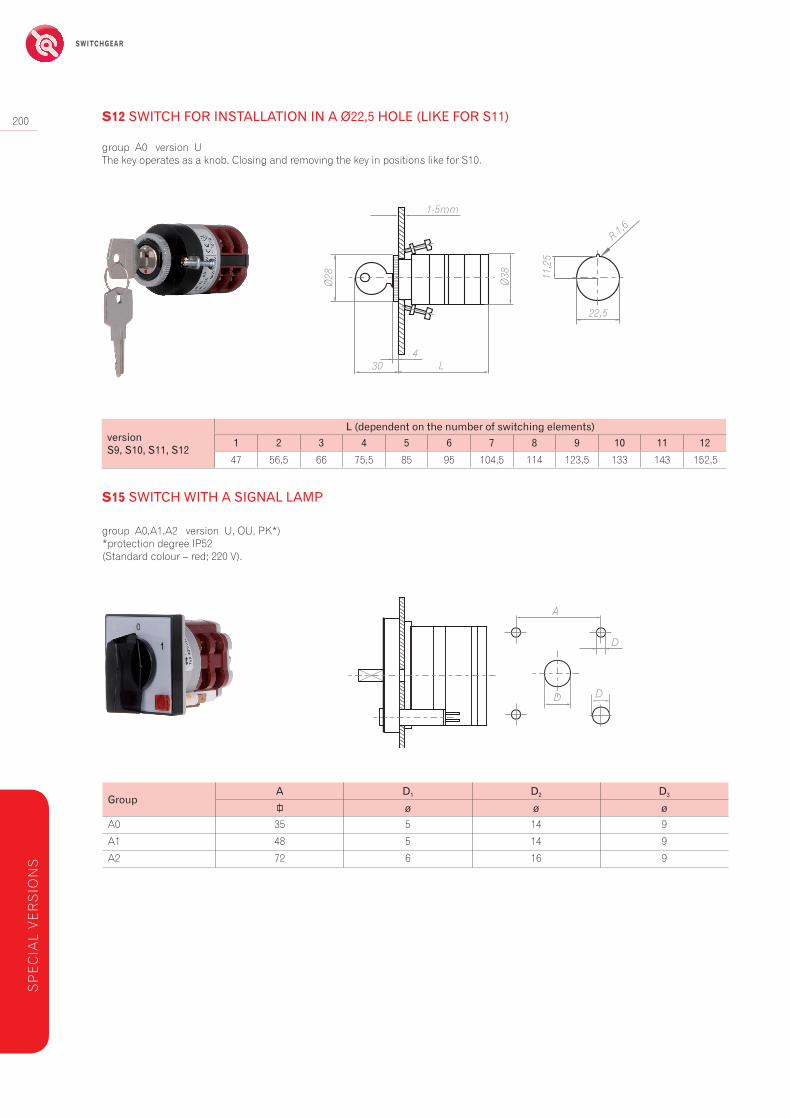
GroupA D1 D2 D3
ø ø øA0 35 5 14 9
A1 48 5 14 9
A2 72 6 16 9
S12SWITCHFORINSTALLATIONINAØ22,5HOLE(LIKEFORS11)
group A0 version UThe key operates as a knob. Closing and removing the key in positions like for S10.
S15SWITCHWITHASIGNALLAMP
group A0,A1,A2 version U, OU, PK*) *protection degree IP52(Standard colour – red; 220 V).
L
Ø28
1-5mm
304
Ø38 11
,25
22,5
R 1,6
A
D
D D
SP
EC
IAL
VE
RS
ION
S

ENERGY SAFELY SWITCHED
201
GrupaA B C D E F G
A0 48 30 21 35 5 10,5 26,5
A1 65 48,5 21 35 9 15 34,5
A2 90 48,5 21 35 9 15 41,5
GroupD1 D2 A E P K M N Lø ø
A1 5 14 48 9,5 25 51 78 36 69
A2 6 16 72 9,5 32 58 99 53 78
S18SWITCHFORINSTALLATIONONDINRAIL(ACCORDINGTO35DINEN50022)
group A0, A1, A2 version U
S19 SWITCHWITHAPROTECTIVEHOUSING(UPTOTWOPACKS)
group A1, A2 version U, OU
Protection to prevent from touching the terminals.
G
1-5mm
E
F A
CB
D
A
D2
D1
M
K
L
E PN
SP
EC
IAL V
ER
SIO
NS
SWITCHGEAR
202
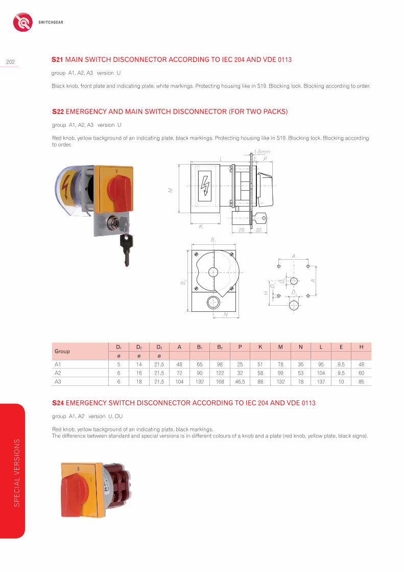
GroupD1 D2 D3 A B1 B2 P K M N L E Hø ø ø
A1 5 14 21,5 48 65 98 25 51 78 36 95 9,5 48
A2 6 16 21,5 72 90 122 32 58 99 53 104 9,5 60
A3 6 18 21,5 104 132 168 46,5 88 132 78 137 10 85
group A1, A2, A3 version U
Red knob, yellow background of an indicating plate, black markings. Protecting housing like in S19. Blocking lock. Blocking according to order.
S22EMERGENCYANDMAINSWITCHDISCONNECTOR(FORTWOPACKS)
group A1, A2 version U, OU
Red knob, yellow background of an indicating plate, black markings.The difference between standard and special versions is in different colours of a knob and a plate (red knob, yellow plate, black signs).
S24EMERGENCYSWITCHDISCONNECTORACCORDINGTOIEC204ANDVDE0113
A
A
HD
1 D2
D3
1-5mm
29 30
E PL
M
K
B1
B 2
N
SP
EC
IAL
VE
RS
ION
S
S21MAINSWITCHDISCONNECTORACCORDINGTOIEC204ANDVDE0113
group A1, A2, A3 version U
Black knob, front plate and indicating plate, white markings. Protecting housing like in S19. Blocking lock. Blocking according to order.
ENERGY SAFELY SWITCHED
203
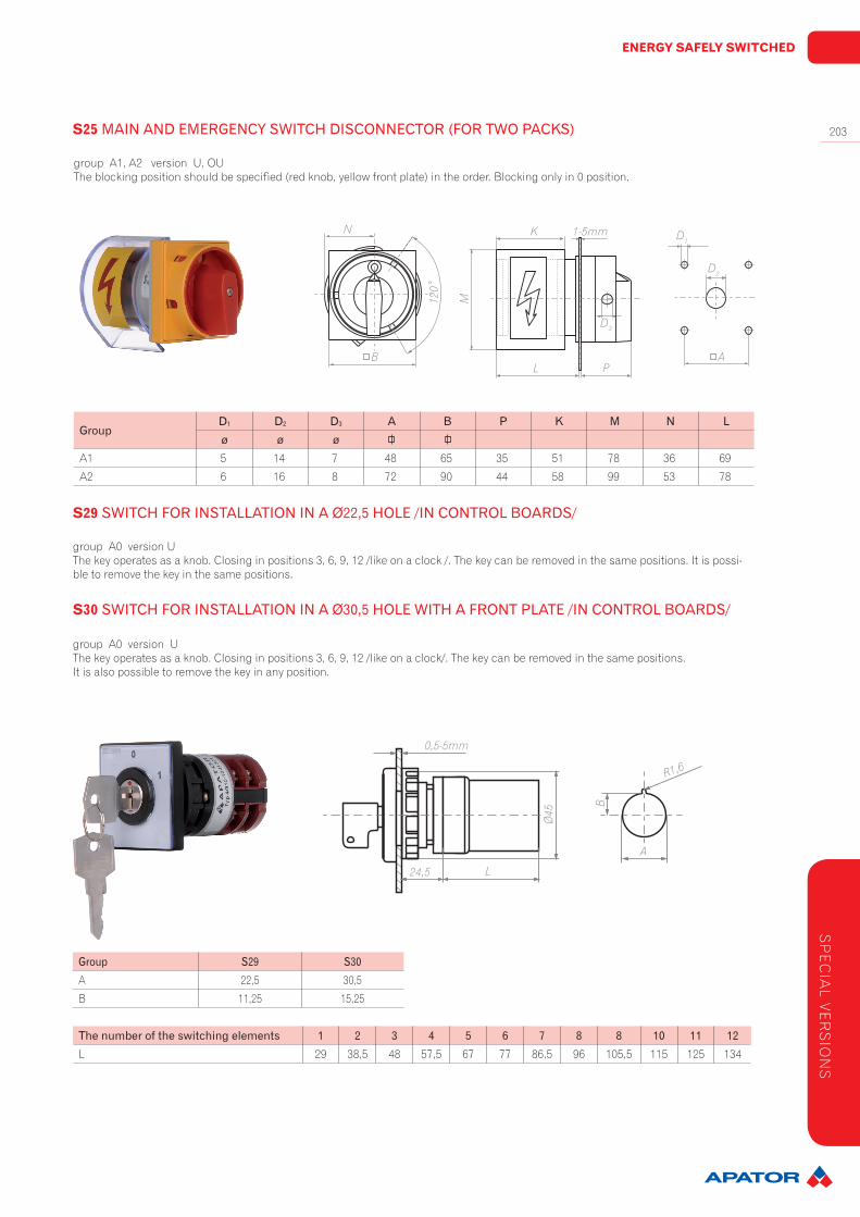
GroupD1 D2 D3 A B1 B2 P K M N L E Hø ø ø
A1 5 14 21,5 48 65 98 25 51 78 36 95 9,5 48
A2 6 16 21,5 72 90 122 32 58 99 53 104 9,5 60
A3 6 18 21,5 104 132 168 46,5 88 132 78 137 10 85
Thenumberoftheswitchingelements 1 2 3 4 5 6 7 8 8 10 11 12L 29 38,5 48 57,5 67 77 86,5 96 105,5 115 125 134
GroupD1 D2 D3 A B P K M N Lø ø ø
A1 5 14 7 48 65 35 51 78 36 69
A2 6 16 8 72 90 44 58 99 53 78
Group S29 S30A 22,5 30,5
B 11,25 15,25
group A1, A2 version U, OU The blocking position should be specified (red knob, yellow front plate) in the order. Blocking only in 0 position.
S25MAINANDEMERGENCYSWITCHDISCONNECTOR(FORTWOPACKS)
group A0 version UThe key operates as a knob. Closing in positions 3, 6, 9, 12 /like on a clock /. The key can be removed in the same positions. It is possi-ble to remove the key in the same positions.
S29SWITCHFORINSTALLATIONINAØ22,5HOLE/INCONTROLBOARDS/
group A0 version UThe key operates as a knob. Closing in positions 3, 6, 9, 12 /like on a clock/. The key can be removed in the same positions.It is also possible to remove the key in any position.
S30SWITCHFORINSTALLATIONINAØ30,5HOLEWITHAFRONTPLATE/INCONTROLBOARDS/
1-5mm
A
D1
D2
D3
L P
K
M
N
B
120˚
0,5-5mm
24,5 L
Ø45
A
B
R1,6
SP
EC
IAL V
ER
SIO
NS
SWITCHGEAR
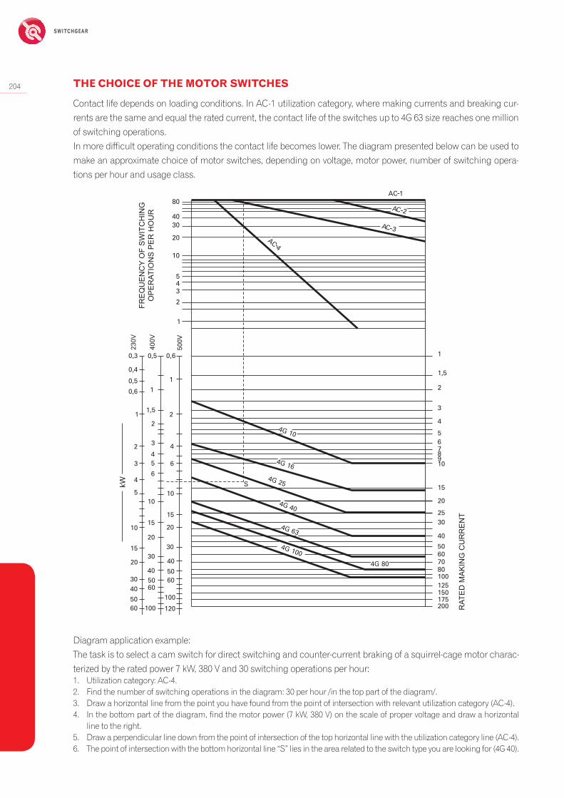
204 THE CHOICE OF THE MOTOR SWITCHES
Contact life depends on loading conditions. In AC-1 utilization category, where making currents and breaking cur-rents are the same and equal the rated current, the contact life of the switches up to 4G 63 size reaches one million of switching operations.In more difficult operating conditions the contact life becomes lower. The diagram presented below can be used to make an approximate choice of motor switches, depending on voltage, motor power, number of switching opera-tions per hour and usage class.
Diagram application example:The task is to select a cam switch for direct switching and counter-current braking of a squirrel-cage motor charac-terized by the rated power 7 kW, 380 V and 30 switching operations per hour:1. Utilization category: AC-4.2. Find the number of switching operations in the diagram: 30 per hour /in the top part of the diagram/.3. Draw a horizontal line from the point you have found from the point of intersection with relevant utilization category (AC-4).4. In the bottom part of the diagram, find the motor power (7 kW, 380 V) on the scale of proper voltage and draw a horizontal
line to the right.5. Draw a perpendicular line down from the point of intersection of the top horizontal line with the utilization category line (AC-4).6. The point of intersection with the bottom horizontal line “S” lies in the area related to the switch type you are looking for (4G 40).
CZ
ĘS
TO
TLI
WO
ŚĆ
ŁĄC
ZE
Ń N
A G
OD
ZIN
Ę
ZN
AM
ION
OW
Y P
RĄ
D Ł
ĄC
ZE
NIO
WY
Ie
0,50,3
0,4
0,5
0,6
4G 10
4G 16
4G 25
4G 40
4G 63
4G 100
AC 4
AC 3
AC 2
4G 80
1
1
1 22
32 445
6
3
4
kW
5
15
10S
1510 20
2030
40
5060
20017515012510080706050
40
3025
20
15
1098765
4
3
2
1,5
1
100
120
2030
405060
3040
5060 100
15
10
6
1,5
0,6
1
2
345
10
20
3040
80AC 1
500V
380V
220V
230V
400V
-
-
-
-
RAT
ED
MA
KIN
G C
UR
RE
NT
FRE
QU
EN
CY
OF
SW
ITC
HIN
GO
PE
RAT
ION
S P
ER
HO
UR

ENERGY SAFELY SWITCHED
205
ORDER FORM
87-100 Toruń, ul. Gdańska nr 4a lok. C4SWITCHING EQUIPMENT SALES OFFICEPhones: 48 (56) 61 91 152Fax: 48 (56) 61 91 295e-mail: [email protected]://www.apator.com.pl
Contracting party:
Address:
Phone:
Fax: e-mail:
Technical data Type of assemblyType and colour of aknob or a handle
Knob rotation angle
Black
Red
Special version
Notes:
Switching diagram:
Number ofpices
Indicating plate description example
osition descriptions on the indicating plate,according to the angle of rotation.
Des
crip
tion
of th
e in
dica
ting
plat
e ac
cord
ing
to c
usto
mer
's re
quire
men
ts.
(to b
e en
tere
d in
the
adja
cent
fiel
ds)
automatic return (onlyafter turning by 30ş
from the stableposition)
impulseinstantaneous
contact)
closedcontact
closedcontactwithout
breaking"overlap ping"
contacts
Example of connectingthe contacts with
bridges
Ord
er fr
om(to
be
copi
ed)
Black
Red