Cam Style Rack & Pinion Style Series MHY2/MHW2 · 320 560 Weight g 0.16 0.54 1.10 2.28 Cam style...
15
Cam actuation style is now standardised ! 180° Angular Gripper Series MHY2/MHW2 Cam Style Rack & Pinion Style 5-241
Transcript of Cam Style Rack & Pinion Style Series MHY2/MHW2 · 320 560 Weight g 0.16 0.54 1.10 2.28 Cam style...

Cam actuation style is now standardised !
180° Angular Gripper
Series MHY2/MHW2 Cam Style Rack & Pinion Style
5-241

Resistance to dusty environmentsReduced opening sizes helps preventforeign substance from entering.
Assembly
Clamping of work
Auto switch mountingat 4 locationsImproved mounting repeatability
Stainless steel fingersare standard.
Effective holdingmoment∗
Nm
71
84
106
131
L
∗At pressure of 0.5MPa
10
16
20
25
MHY2-10D
MHY2-16D
MHY2-20D
MHY2-25D
Bore sizemm
Model
70
150
320
560
Weightg
0.16
0.54
1.10
2.28
Cam styleSeries MHY
Rack & PinionstyleSeries MHW
10 16 20 25 32 40 50
Variation
Bore size (mm)
Series MHY/Cam Style
Overall lengthLmm
180° Angular Gripper Cam Style Rack & Pinion Style
Series MHY2/MHW2
Light and compact size in small bore sizes
Bearings are standard.
Dust proof construction
Two finger styles available.
Holding mement∗
Nm
Over lengthLmm
L
∗At the pressure of 0.5MPa
20
25
32
40
50
MHW2-20D
MHW2-25D
MHW2-32D
MHW2-40D
MHW2-50D
Bore sizemm
Model
0.30
0.73
1.61
3.70
8.27
Clamping work
Solid state switchD-Y5/Y6 typeD-Y7 typeWater resistant2 color indicationD-Y7BA type
INDEX
Applicable auto switch Page
P.5-248
P.5-256
Unique seal design allows shorter total length constructionand constant holding force when opening and closing fingers.
68
78
93.5
117.5
154
Weightg
300
510
905
2135
5100
Transferring work
Solid state switchD- M9/M9 W typeWater resistant2 color indicationD-M9BA Type
Auto switch mountingat 4 locations
Key connection isideal for impact
resistance.Key connection between fingerand shaft prevents finger angleslippage during impact. Seal arrangement protects gripper from harsh
dusty environments.
Flat finger type Right angle finger type
(PAT.PEND)
Series MHW/Rack & Pinion Style
5-242

Resistance to dusty environmentsReduced opening sizes helps preventforeign substance from entering.
Assembly
Clamping of work
Auto switch mountingat 4 locationsImproved mounting repeatability
Stainless steel fingersare standard.
Effective holdingmoment∗
Nm
71
84
106
131
L
∗At pressure of 0.5MPa
10
16
20
25
MHY2-10D
MHY2-16D
MHY2-20D
MHY2-25D
Bore sizemm
Model
70
150
320
560
Weightg
0.16
0.54
1.10
2.28
Cam styleSeries MHY
Rack & PinionstyleSeries MHW
10 16 20 25 32 40 50
Variation
Bore size (mm)
Series MHY/Cam Style
Overall lengthLmm
180° Angular Gripper Cam Style Rack & Pinion Style
Series MHY2/MHW2
Light and compact size in small bore sizes
Bearings are standard.
Dust proof construction
Two finger styles available.
Holding mement∗
Nm
Over lengthLmm
L
∗At the pressure of 0.5MPa
20
25
32
40
50
MHW2-20D
MHW2-25D
MHW2-32D
MHW2-40D
MHW2-50D
Bore sizemm
Model
0.30
0.73
1.61
3.70
8.27
Clamping work
Solid state switchD-Y5/Y6 typeD-Y7 typeWater resistant2 color indicationD-Y7BA type
INDEX
Applicable auto switch Page
P.5-248
P.5-256
Unique seal design allows shorter total length constructionand constant holding force when opening and closing fingers.
68
78
93.5
117.5
154
Weightg
300
510
905
2135
5100
Transferring work
Solid state switchD- M9/M9 W typeWater resistant2 color indicationD-M9BA Type
Auto switch mountingat 4 locations
Key connection isideal for impact
resistance.Key connection between fingerand shaft prevents finger angleslippage during impact. Seal arrangement protects gripper from harsh
dusty environments.
Flat finger type Right angle finger type
(PAT.PEND)
Series MHW/Rack & Pinion Style
5-243
180˚ Angular Gripper Series MHY2/MHW2

MHW2-25D
Pressure 0.7MPa
20 40 60Holding point L (mm)
10080
20
10
0
Hol
ding
forc
e (N
)
50
0.5
0.4
0.3
0.2
30
40
MHW2-32D
Pressure 0.7MPa
20 40 60Holding point L (mm)
80 100 120
20
0
Hol
ding
forc
e (N
)
100
0.5
0.4
0.3
0.2
60
80
40
MHW2-20D
Pressure 0.7MPa
20 40 60Holding point L (mm)
80
10
5
0
Hol
ding
forc
e (N
)
25
0.5
0.4
0.3
0.2
15
20 0.6
0.6
0.6
MHW2-50D
Pressure 0.7MPa
40Holding point L (mm)
12080 160 200
150
50
0
Hol
ding
forc
e (N
)
300
0.5
0.4
0.3
0.2
200
250
MHW2-40D
Pressure 0.7MPa
20 40 60Holding point L (mm)
80 100 120 140 1600
Hol
ding
forc
e (N
)
0.5
0.4
0.3
0.2
20
0.6
0.6
40
60
80
100
120
140
160
100
Confirmation of holding point
MHY
0.1 0.2 0.4 0.5
Pressure P (MPa)
0.3 0.6
20
0
Ove
rhan
g H
(m
m)
60
40
MHW
0.1 0.2 0.3
Pressure P (MPa)
0.4 0.5 0.6 0.70
Ove
rhan
g H
(m
m)
50
MHW2-20D
100
150
200
MHW2-25DMHW2-32DMHW2-40DMHW2-50D
MHY2-10DMHY2-16DMHY2-20DMHY2-25D
50
30
10
Holding point
Holding point
HH
Work should be held at a point within the range ofoverhanging distance (H) for a given pressureindicated in the tables on the right.When the work is held at a point outside of therecommended range for a given pressure, it maycauses adverse effect on the product life.
Step 2
5-244
Series MHY2/MHW2
How to Select
MHY2-16DGuidelines on model selection according to work weight
Although the condition differs according to thecoefficient of friction between the attachmentand work, select a model that can produce aholding force of 10 to 20 times the workweight.Further allowance should be provided whengreat acceleration or impact is expectedduring work transfer.
Work weight: 0.05kg
Holding point L = 35mm
Operating pressure: 0.6MPa
When MHY2-16D is selected, theholding force is determined to be 13Naccording to the holding pointdistance (L = 35mm) and the pressure(0.6MPa).The holding force is 26 times the workweight meeting the guideline thatholding force should be more than 20times the set holding force value.
25
20
15
10
5
020 30 40 50
Holding point L (mm)
Hol
ding
forc
e (N
)
Pressure 0.6MPa
Condition check Calculation of required holding force Model selection from the holding force graph
Example
0.3
0.2
0.1
0.5
0.4
60 70
13
Procedure
Confirm holding force
Confirm moment of inertia ofattachments
Confirm holding force
How to Select the Applicable Model
Confirm holding forceStep 1
Step 1
MHY2-10D
Pressure 0.6MPa
20 30 50 60Holding point L (mm)
40
4
2
0
Hol
ding
forc
e (N
)
10
0.5
0.4
0.3
0.2
0.1
6
8
MHY2-16D
Pressure 0.6MPa
20 30 50 60Holding point L (mm)
40
15
10
0
Hol
ding
forc
e (N
)
35
0.5
0.4
0.3
0.2
0.1
25
30
70
20
5
MHY2-20DPressure 0.6MPa
30 40 60 70Holding point L (mm)
50 80
20
10
0
Hol
ding
forc
e (N
)
50
0.5
0.4
0.3
0.2
0.1
30
40
MHY2-25DPressure 0.6MPa
30 40 60 70Holding point L (mm)
50 80
20
0
Hol
ding
forc
e (N
)
100
0.5
0.4
0.3
0.2
0.1
60
80
40
90
Effective holding force
Indication of effective holding forceThe holding force shown in the tables representsthe holding force of one finger when all fingers and attachments are in contact with the work. (F: Thrust of one finger)
F FFF
L
L
Series MHY2/MHW2 Double acting
External hold
Ex.) For setting the holding force to be at least 20 times the work weight; Required holding force = 0.05kg X 20 X 9.8m/s2
= 10N min.
Step 2 Step 3

MHW2-25D
Pressure 0.7MPa
20 40 60Holding point L (mm)
10080
20
10
0
Hol
ding
forc
e (N
)
50
0.5
0.4
0.3
0.2
30
40
MHW2-32D
Pressure 0.7MPa
20 40 60Holding point L (mm)
80 100 120
20
0
Hol
ding
forc
e (N
)100
0.5
0.4
0.3
0.2
60
80
40
MHW2-20D
Pressure 0.7MPa
20 40 60Holding point L (mm)
80
10
5
0
Hol
ding
forc
e (N
)
25
0.5
0.4
0.3
0.2
15
20 0.6
0.6
0.6
MHW2-50D
Pressure 0.7MPa
40Holding point L (mm)
12080 160 200
150
50
0
Hol
ding
forc
e (N
)
300
0.5
0.4
0.3
0.2
200
250
MHW2-40D
Pressure 0.7MPa
20 40 60Holding point L (mm)
80 100 120 140 1600
Hol
ding
forc
e (N
)
0.5
0.4
0.3
0.2
20
0.6
0.6
40
60
80
100
120
140
160
100
Confirmation of holding point
MHY
0.1 0.2 0.4 0.5
Pressure P (MPa)
0.3 0.6
20
0
Ove
rhan
g H
(m
m)
60
40
MHW
0.1 0.2 0.3
Pressure P (MPa)
0.4 0.5 0.6 0.70
Ove
rhan
g H
(m
m)
50
MHW2-20D
100
150
200
MHW2-25DMHW2-32DMHW2-40DMHW2-50D
MHY2-10DMHY2-16DMHY2-20DMHY2-25D
50
30
10
Holding point
Holding point
HH
Work should be held at a point within the range ofoverhanging distance (H) for a given pressureindicated in the tables on the right.When the work is held at a point outside of therecommended range for a given pressure, it maycauses adverse effect on the product life.
Step 2
5-245
180˚ Angular Gripper Series MHY2/MHW2Series MHY2/MHW2
How to Select
MHY2-16DGuidelines on model selection according to work weight
Although the condition differs according to thecoefficient of friction between the attachmentand work, select a model that can produce aholding force of 10 to 20 times the workweight.Further allowance should be provided whengreat acceleration or impact is expectedduring work transfer.
Work weight: 0.05kg
Holding point L = 35mm
Operating pressure: 0.6MPa
When MHY2-16D is selected, theholding force is determined to be 13Naccording to the holding pointdistance (L = 35mm) and the pressure(0.6MPa).The holding force is 26 times the workweight meeting the guideline thatholding force should be more than 20times the set holding force value.
25
20
15
10
5
020 30 40 50
Holding point L (mm)
Hol
ding
forc
e (N
)
Pressure 0.6MPa
Condition check Calculation of required holding force Model selection from the holding force graph
Example
0.3
0.2
0.1
0.5
0.4
60 70
13
Procedure
Confirm holding force
Confirm moment of inertia ofattachments
Confirm holding force
How to Select the Applicable Model
Confirm holding forceStep 1
Step 1
MHY2-10D
Pressure 0.6MPa
20 30 50 60Holding point L (mm)
40
4
2
0
Hol
ding
forc
e (N
)
10
0.5
0.4
0.3
0.2
0.1
6
8
MHY2-16D
Pressure 0.6MPa
20 30 50 60Holding point L (mm)
40
15
10
0
Hol
ding
forc
e (N
)
35
0.5
0.4
0.3
0.2
0.1
25
30
70
20
5
MHY2-20DPressure 0.6MPa
30 40 60 70Holding point L (mm)
50 80
20
10
0
Hol
ding
forc
e (N
)
50
0.5
0.4
0.3
0.2
0.1
30
40
MHY2-25DPressure 0.6MPa
30 40 60 70Holding point L (mm)
50 80
20
0
Hol
ding
forc
e (N
)
100
0.5
0.4
0.3
0.2
0.1
60
80
40
90
Effective holding force
Indication of effective holding forceThe holding force shown in the tables representsthe holding force of one finger when all fingers and attachments are in contact with the work. (F: Thrust of one finger)
F FFF
L
L
Series MHY2/MHW2 Double acting
External hold
Ex.) For setting the holding force to be at least 20 times the work weight; Required holding force = 0.05kg X 20 X 9.8m/s2
= 10N min.
Step 2 Step 3

5-246
Confirm moment of inertia of attachments
MHY2-16D
0.2 0.4 0.5
Operating time (s/90°)0.30.1
1.0
Iner
tia m
omen
t (X
10-4
kgm
2 )
3.0
2.0
2.5
1.5
0.5
Confirm the moment of inertia for the attachment at one side.Calculate the moment of inertia for A and B separately as shown in the figures on the right.
Procedure Formula Calculation example
Operating model: MHY2-16DOpening time: 0.15sa = 40 (mm)b = 7 (mm)c = 8 (mm)d = 5 (mm)e = 10 (mm)f = 12 (mm)
Material of attachment: Aluminum alloy(Specific gravity = 2.7)r1 = 37 (mm)
m1 = 40 X 7 X 8 X 2.7 X 10-6
Iz1 = {0.006 X (402+7
2)/12} X 10-6
= 0.8 X 10⁻⁶ (kgm2) = 0.8 X 10⁻⁶+ 0.006 X 37
2 X 10-6
= 9.0 X 10⁻⁶(kgm2)
0.13 X 10⁻⁴ (kgm2) < 0.9 X 10⁻⁴ (kgm2)Possible to use this model MHY2-16Dcompletely.
0
0.9
r2 = 47(mm)
m2 = 5 X 10 X 12 X 2.7 X 10-6
= 0.002(kg)Iz2 = {0.002 X (52 + 102)/12} X 10-6
= 0.02 X 10⁻⁶ (kgm2)IB = 0.02 X 10⁻⁶ + 0.002 X 472 X 10-6
= 4.4 X 10⁻⁶ (kgm2) I = 9.0 X 10⁻⁶ + 4.4 X 10-6
= 13.4 X 10-6 = 0.13 X 10⁻⁴ (kgm2)
Moment of inertia around Z1 axis
Iz1 = {m1(a2+ b
2)/12} X 10-6
Moment of inertia around Z axisIA = IZ1 + m1r1
2 X 10⁻⁶
A part
B part
zr1
z1
Calculation of weightm1 = a X b X c X Specific gravity
z
r2
Z2
Calculation of weightm2 = d X e X f X Specific gravity
A part
B part
d
f
e
c
ab
Moment of inertia around Z2 axis
Iz2 = {m2(d2 + e2)/12} x 10-6
∗
Moment of inertia of attachment <Allowable moment of intertia
The moment of inertia is determined to be 0.9 X 10⁻⁴
(kgm2) according to the operatingtime (0.15s) from the graph on the left.
A part B part
Series MHY2/MHW2How to Select the Applicable Model
Step 3
Moment of inertia around Z axisIB = IZ2 + m2r2
2 x 10⁻⁶
Total moment of inertiaI = IA + IB
∗
(∗: constant for unit conversion)
Check the operating conditions,dimensions of attachment, etc.
Determine the allowable moment of inertia from the graph.
Confirm the moment of inertia of one attachment is within the allowable range.
Calculate the moment of inertia of attachment.
= 0.006(kg)
IA
∗
∗

MHY2-10D
0.1 0.2 0.4 0.50.3
0.4
0.2
0
1.0
0.6
0.8
kgm2
kgm2
kg
kg
mm
mm
1.2
MHY2-16D
0.1 0.2 0.4 0.50.3
1.0
0.5
0
2.5
1.5
2.0
3.0
MHY2-20D
0.2 0.4 0.6 0.8
2
1
0
5
3
4
6
MHY2-25D
0.2 0.4 0.6 0.8 1.0
10
5
0
15
20
MHW2-20D
0.1 0.2 0.3
2
1
0
5
3
4
6
MHW2-25D
0.2 0.4 0.50.3
10
5
0
15
20
MHW2-32D
0.2 0.4 0.50.3 0.6
20
10
0
50
30
40
MHW2-40D
0.2 0.4 0.6 0.8 1.0
100
50
0
150
200
MHW2-50D
0.2 0.4 0.6 0.8 1.0 1.2
200
100
0
500
300
400
600
Symbol
Allowable range of inertia moment of attachment
Symbol Definition Unit
Z
Z1
Z2
I
IZ1
IZ2
—
—
—
kgm2
kgm2
kgm2
Finger rotation axis
Axis on the centre gravity of A part of attachment and parallel to Z
Axis on the centre gravity of B part of attachment and parallel to Z
Total moment of inertia for attachment
Inertia moment around the Z1 axis of A part of attachment
Inertia moment around the Z2 axis of B part of attachment
Symbol Definition Unit
IA
IB
m1
m2
r1
r2
Moment of inertia around the Z axis of A part of attachment
Moment of inertia around the Z axis of B part of attachment
Weight of A part of attachment
Weight of B part of attachment
Distance between Z and Z1 axis
Distance between Z and Z2 axis
Operating time (s/90°)Operating time (s/90°)
Operating time (s/90°)
Operating time (s/90°)
Mom
ent o
f ine
rtia
(X
10-4
kgm
2 )
Mom
ent o
f ine
rtia
(X
10-4
kgm
2 )
Mom
ent o
f ine
rtia
(X
10-4
kgm
2 )
Mom
ent o
f ine
rtia
(X
10-4
kgm
2 )
Mom
ent o
f ine
rtia
(X
10-4
kgm
2 )
Mom
ent o
f ine
rtia
(X
10-4
kgm
2 )
Mom
ent o
f ine
rtia
(X
10-4
kgm
2 )
Mom
ent o
f ine
rtia
(X
10-4
kgm
2 )
Mom
ent o
f ine
rtia
(X
10-4
kgm
2 )
Operating time (s/90°)
Operating time (s/90°)
Operating time (s/90°)
Operating time (s/90°)
Operating time (s/90°)
5-247
180˚ Angular Gripper Series MHY2/MHW2

5-248
MHY 2
How to Order
Series MHY2 ø10, ø16, ø20, ø25
2
10mm
16mm
20mm
25mm
Action
—
S
Number of fingers2 fingers
Bore size10
16
20
25
D Double acting
Auto switch
Number of auto switches2
1
— Without auto switch
16 2D M9NL S
180° AngularGripper
Cam Style
∗Refer to the table below for the applicable auto switches.
Applicable Auto Switches
∗Lead wire length: 0.5m·········– (Example) M9N3m············L (Example) M9NL
Note 1) Refer to "Auto Switch Specifications" on p.6-15
Symbol
M9NV
M9PV
M9BV
M9NWV
M9PWV
M9BWV
Electrical entry
Perpendicular In-line
M9N
M9P
M9B
M9NW
M9PW
M9BW
Type
Solidstate
Special function
Load voltage
ACDC
24V
Wiring(Output)
3 wire(NPN)
3 wire(PNP)
2 wire
3 wire(NPN)
3 wire(PNP)
2 wire
With
IndicatorElectricalentry
Grommet
Diagnosisindicator(2 colour
indication)
Lead wire length (m)
0.5(–)
3(L)
Applicableload
RelayPLC
12V
5V12V
12V
5V12V
–: Standard tap mounting
Finger option
2: Opening/closing direction through hole
—
—

Fluid
Operating pressure
Ambient and fluid temperature
Repeatability
Max. operating frequency
Lubrication
Action
Auto switch (Optional) Note)
Air
0.1 to 0.6MPa
–10 to 60oC
±0.2mm
60c.p.m
Not required
Double acting
Solid state switch (3 wire, 2 wire)
Model Bore size(mm)
Effective holding force(Nm) (1)
Opening angle (Both sides) (2)Weight
(g)
Specifications
Note) Refer to p. 6-15 for details of auto switch specifications.
Note 1) At the pressure of 0.5MPaNote 2) Not including auto switch
Openingside
Model
MHY2-10D
MHY2-16D
MHY2-20D
MHY2-25D
10
16
20
25
0.16
0.54
1.10
2.28
70
150
320
560
180o –3o
Symbol
Double acting
Refer to the "How to Select the Applicable Model" on p.5-244Refer to p.5-244 and 5-245 for the details of effective holding force and allowableoverhanging distance.
Closingside
5-249
180˚ Angular Gripper Series MHY2

No.
q
w
e
r
t
y
u
i
Description Material
Aluminum alloy
ø10: Stainless steelø16 to 25: Aluminum alloy
Stainless steel
Stainless steel
Resin
Resin
Stainless steel
Sintered alloy steel
Note
Hard anodized
ø16 to 25:Chromated
Heat treatment
Heat treatment
Nitriding
No.
o
!0
!1
!2
!3
!4
!5
!6
Description Material
Sintered alloy steel
Stainless steel
Urethane rubber
High carbon chrome bearing steel
Note
Nitriding
Nickel plated
No. Description MaterialMHY2-10D MHY2-16D MHY2-20D MHY2-25D
Construction
Component Parts
Replacement Parts: Seal KitsKit No.
Body
Piston
Joint
Finger
Cap
Ware ring
Shaft
Bushing A
Bushing B
End plate
Bumper
Cylindrical roller
Joint roller
Rubber magnet
C-shape snap ring
Piston bolt
!7
!8
!9
@0
Seal kit NBR MHY10-PS MHY16-PS MHY20-PS MHY25-PS
Component Parts
ø 10 ø 16 ø 20, ø 25
Open
Closed
Carbon steel
Synthetic rubber
Carbon steel
Stainless steel
r o !8 e w !7 t !5 r o !8 e !6 w @0 !7 t !5 r o !8 e !6 w @0 !7 t !5
!0 u !2 i q !1 !4 y !9 !0 u !2 i q !1 !4 y !9 !0 u !2 i q !1 !4 y !9!3
5-250
Series MHY2

MHY2-10D
2 X M3 Depth 4(Mounting thread)
9
30
9
4
3H9 +0.025 0
6 –0.005–0.025
4 X M3
(Thread for mounting attachment)
(Lim
ited
area
for m
ount
ing
atta
chm
ent∗ )
36
12
2223
.5
4 4 X M3 Depth 6(Mounting thread)
(Mounting hole)
Dimensions
24
18
35
47.5
58
Positioning pin hole
9
15
3024
ø11H9
Depth 1.5
2 X M3, 6 deep
(Mounting thread)
Auto switch mounting groove position
3
ø4
132
23 7
3
O
S
M5(Finger opening port)
M5(Finger closing port)
Depth 3
Pin hole positioning
∗ Do not extend the attachment from limited area for mounting to avoid interference with the attachment or main body.
MHY2-10D2Opening/closing direction through hole type
3612
4- ø3.4
(Hole for mounting attachment)
6–0.005–0.025
(Lim
ited
area
for m
ount
ing
atta
chm
ent∗ )
2 - ø 3.4
+ 0.043 0
5-251
180˚ Angular Gripper Series MHY2

MHY2-16D
Dimensions
2 X M4 Depth 5(Mounting thread)
12
33
154
3830
2 X M4 Depth 8
(Mounting thread)
Positioning pin hole
12
20
4 X M4 Depth 8
(Mounting thread)
5
30
20
41
55.5
69
2828
.5
8_0.005_0.025
4 X M3
(Thread for mounting attachment)
47
25 7
8
O
S
M5(Finger opening port)
M5(Finger closing port)
3
18
ø4
2.5
Auto switch mounting groove position
Pin hole positioning
(Lim
ited
area
for m
ount
ing
atta
chm
ent∗ )
14
∗ Do not extend the attachment from limited area formounting to avoid interference with the attachment or main body.
MHY2-16D2Opening/closing direction through hole type
2-ø4.5
(Mounting hole)
ø17H9 Depth 1.5
3H9 Depth 3
4714
4-ø 3.4
(Hole for mounting attachment)
8–0.005–0.025
(Lim
ited
area
for m
ount
ing
atta
chm
ent∗ )
+0.025 0
+0.043 0
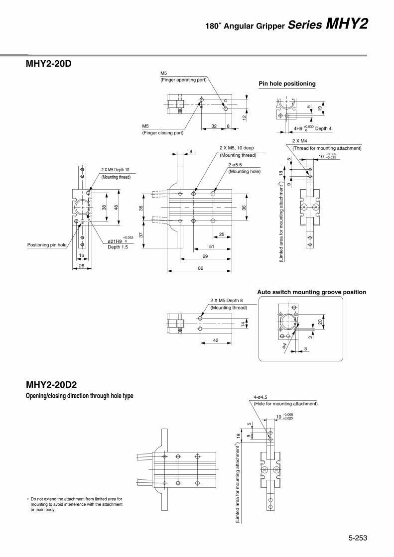
MHY2-20D
10–0.005–0.0255
9
18
3637 25
51
69
86
36
8
4838
16
26
3
20
3
19
5
MHY2-20D2Opening/closing direction through hole type
5918
10–0.005–0.025
Pin hole positioning
Auto switch mounting groove position
4H9 Depth 4
14
42
2 X M5 Depth 8
(Mounting thread)
2 X M5, 10 deep
2-ø5.5(Mounting hole)
12
O
S
32 8
M5(Finger operating port)
M5(Finger closing port)
4-ø4.5(Hole for mounting attachment)
(Mounting thread)
2 X M4
(Thread for mounting attachment)
(Lim
ted
area
for
mou
ntin
g at
tach
men
t∗ )
(Lim
ted
area
for
mou
ntin
g at
tach
men
t∗ )
2 X M5 Depth 10
Postioning pin hole
(Mounting thread)
+0.030 0
ø21H9 Depth 1.5
+0.052 0
ø4
∗ Do not extend the attachment from limited area for mounting to avoid interference with the attachment or main body.
5-252
Series MHY2
MHY2-16D
Dimensions
2 X M4 Depth 5(Mounting thread)
12
33
154
3830
2 X M4 Depth 8
(Mounting thread)
Positioning pin hole
12
20
4 X M4 Depth 8
(Mounting thread)
5
30
20
41
55.5
69
2828
.5
8_0.005_0.025
4 X M3
(Thread for mounting attachment)
47
25 7
8
O
S
M5(Finger opening port)
M5(Finger closing port)
3
18
ø4
2.5
Auto switch mounting groove position
Pin hole positioning
(Lim
ited
area
for m
ount
ing
atta
chm
ent∗ )
14
∗ Do not extend the attachment from limited area formounting to avoid interference with the attachment or main body.
MHY2-16D2Opening/closing direction through hole type
2-ø4.5
(Mounting hole)
ø17H9 Depth 1.5
3H9 Depth 3
4714
4-ø 3.4
(Hole for mounting attachment)
8–0.005–0.025
(Lim
ited
area
for m
ount
ing
atta
chm
ent∗ )
+0.025 0
+0.043 0
MHY2-20D
10–0.005–0.0255
9
18
3637 25
51
69
86
36
8
4838
16
26
3
20
3
19
5
MHY2-20D2Opening/closing direction through hole type
5918
10–0.005–0.025
Pin hole positioning
Auto switch mounting groove position
4H9 Depth 4
14
42
2 X M5 Depth 8
(Mounting thread)
2 X M5, 10 deep
2-ø5.5(Mounting hole)
12
O
S
32 8
M5(Finger operating port)
M5(Finger closing port)
4-ø4.5(Hole for mounting attachment)
(Mounting thread)
2 X M4
(Thread for mounting attachment)
(Lim
ted
area
for
mou
ntin
g at
tach
men
t∗ )
(Lim
ted
area
for
mou
ntin
g at
tach
men
t∗ )
2 X M5 Depth 10
Postioning pin hole
(Mounting thread)
+0.030 0
ø21H9 Depth 1.5
+0.052 0
ø4
∗ Do not extend the attachment from limited area for mounting to avoid interference with the attachment or main body.
5-253
180˚ Angular Gripper Series MHY2

MHY2-25D
12–0.005–0.025
612
22.5
4545
42
10
23
5
46 58
18
30
30
60
86
107
24
3
3
MHY2-25D2Opening/closing direction through hole type
61222
.5
12 –0.005–0.025
Dimensions
∗ Do not extend the attachment from limited area for mounting to avoid interference with the attachment or main body.
Auto switch mounting groove position
4-ø5.5(Hole for mounting attachment)
Pin hole positioning
14
O
S
42 8
M5(Finger operating port)
M5
(Finger closing port)
ø4
4H9 Depth 4+0.030 0
2 X M6 Depth 12
(Mounting thread)
ø26H9 Depth 1.5
+0.052 0Postioning
pin hole16
50
2 X M6 Depth 10
(Mounting thread)
4 X M6 Depth 12
2-ø6.6(Mounting hole)
(Mounting thread)
4 X M5
(Thread for mounting attachment)
(Lim
ted
area
for
mou
ntin
g at
tach
men
t∗ )
(Lim
ted
area
for
mou
ntin
g at
tach
men
t∗ )
5-254
Series MHY2

D-M9N(V)D-M9B(V)
Red lightat ON
GripperModel No.
Protrusion
Max. protrusion of auto switch from edge of body (L)
Auto Switch Hysteresis
In-line Perpendicular
Auto switchmodel No.
Red lightat ON
Green lightat ON
Green lightat ON
2°4°2°3°2°3°1°2°
Finger fullyclosedFinger fullyopen
Finger fullyopen
Finger fullyopen
Finger fullyopen
Finger fullyclosed
Finger fullyclosed
Finger fullyclosed
D-M9BA
O
S
O
S
O
S
O
S
MHY2-10D
MHY2-16D
MHY2-20D
MHY2-25D
—
3
—
3
—
—
—
—
—
8
—
8
—
5
—
3
—
13
—
13
—
10
—
9
—
6
—
7
—
4
—
3
—
1
—
1
—
—
—
—
—
1
—
1
—
—
—
—
—
8
—
8
—
5
—
3
MHY2-10D
MHY2-16D
MHY2-20D
MHY2-25D
D-M9NW(V)
2°4°2°3°2°3°1°2°
4°7°4°6°3°5°3°5°
2°4°2°3°2°3°1°2°
3°5°2°4°2°3°2°3°
D-M9N D-M9BD-M9BA D-M9NW D-M9NV D-M9BVD-M9NWV
When auto switch D-M9BA is used
When auto switch D-M9N is used
When auto switch D-M9V is used
L
L
L
Unit: mm
Switch return position(OFF)
Switch return position(OFF)
Hysteresis
Switch operating position (ON)
Switch operatingposition (ON)
Hysteresis
Auto switches have a differential like a micro switch. Please refer to thefollowing table as a guide when setting auto switch positions.
Note) Use a watchmakers screwdrivers with a grip diameter of 5 to 6 mm to tighten the auto switch mounting screw. Use a tightening torque of 0.05 to 0.1Nm. As a rough guide, tighten the screw an additional 90° after feeling a tighten resistance.
Auto switch
Straight bladedwatchmakers screwdriver
To set the auto switch, insert the auto switch into the installation groove of the gripper from the direction indicated in the following drawing.After establishing the installation position, tighten the attached switch mounting screw with a straight bladed watchmakers screwdriver.
The projection of an auto switch from the edge of the body is shown in thetable below. Use the table as a guideline for mounting.
Note) 2 color indicator type and perpendicular entry type protrude in the direction of the lead wire entry.
Switch mounting screwM2.5 X 4l
ø5 to ø6
Setting Method of Auto Switch Projection of Auto Switch from Body Edge
5-255
180˚ Angular Gripper Series MHY2