CAM-LOCKING -...
18
MXL-C-27487F 19 September 1986 SUPERSEDING MIL-C-27487E 16 July 1980 MILITARY SPECIFICATION COUPLING HALVES, QUICK-DISCO~CT, CAM-LOCKING TYPE This specification is approved for use by all Departments and Agencies of the Department of Defense. 1. SCOPE 1.1 Scope. This specification covers cam-locking type, quick-disconnect coupling halves. 1.2 Classification. Coupling halves should be furnished in the types, classes and sizes designated by the applicable MS or other engineering standard drawings approved by the procuring activity (see 6.2). Type I - Male, internal pipe thread. - MS27020 Type 11 - Male, hose shank. - MS27021 Type 111 - Male, external pipe thread. - MS27022 Type IV - Male, flanged. - MS27023 Size - 2 inch. Size - 2-1/2 inch. Size - 3 inch. Size - 4 inch. Size - 6 inch. Class 1 - Aluminum. Class 2 - Brass. eneficial comments (recommendations, additions, deletions) and any pertinent ata which may be of use in improving this document should be addressed to: USA Belvoir Research, Development, and Engineering Center, ATTN: STRBE-TSE, Fort Belvoir, VA 22060-5606 by using the self-addressed Standardization Document Improvement Proposal (DD Form 1426) appearing at the end of this document or by AMSC N/A FSC 4730 DISTRIBUTION STATEMENT A. Approved for public release; distribution is unlimited. Downloaded from http://www.everyspec.com
Transcript of CAM-LOCKING -...

MXL-C-27487F19 September 1986SUPERSEDINGMIL-C-27487E16 July 1980
MILITARY SPECIFICATION
COUPLING HALVES, QUICK-DISCO~CT,
CAM-LOCKING TYPE
This specification is approved for use by all Departments and Agenciesof the Department of Defense.
1. SCOPE
1.1 Scope. This specification covers cam-locking type, quick-disconnect
coupling halves.
1.2 Classification. Coupling halves should be furnished in the types,classes and sizes designated by the applicable MS or other engineering standarddrawings approved by the procuring activity (see 6.2).
Type I - Male, internal pipe thread. - MS27020
Type 11 - Male, hose shank. - MS27021
Type 111 - Male, external pipe thread. - MS27022
Type IV - Male, flanged. - MS27023
Size - 2 inch.Size - 2-1/2 inch.Size - 3 inch.Size - 4 inch.Size - 6 inch.Class 1 - Aluminum.Class 2 - Brass.
eneficial comments (recommendations, additions, deletions) and any pertinent
ata which may be of use in improving this document should be addressed to: USA
Belvoir Research, Development, and Engineering Center, ATTN: STRBE-TSE, Fort
Belvoir, VA 22060-5606 by using the self-addressed Standardization DocumentImprovement Proposal (DD Form 1426) appearing at the end of this document or by
AMSC N/A FSC 4730
DISTRIBUTION STATEMENT A. Approved for public release; distribution is unlimited.
Downloaded from http://www.everyspec.com

Type V
Type VI
Type VII
Type VIIISizeSizeSizeSizeSizeClass 1Class 2
SizeSizeSizeSizeSizeSizeClass 1Class 2
Type IX
Type XSizeSizeSizeSizeSizeSizeSizeSizeSizeSizeClass 1Class 2
Type XI
SizeSizeSizeSizeSize
MIL-C-27487F
Female, internal pipe thread=
Female, hose shank.
Femalej external pipe threado
Female, flanged circular.- 2 inch- 2-1/2 inch.
- 3 inch.- 4 inch.- 6 inch.- Aluminum.- Brass.
Female, flanged, hexagon.- 1-1/2 inch.- z inch.- 2-1/2 inch.- 3 inch.- 4 inch.- 6 inch.
Aluminum.Brass.
Cap, dust.
plug, dust,1/2 inch.3/4 inch.1 inch.1-1/4 inch.1-1/2 inch.
2 inch.2-1/2 inch.
3 inch.4 inch.6 inch.Aluminum.Bronze or brass.
Reducer, male by female and femaleby male quick-disconnect, cam-locking type.
Nominal end sizeFemale Male
-4 x 3 inch.
-4 x 2 inch.
- 3 x 2 inch.
- 2 x 1-1/2 inch.
- l-1~2 x 1 inch.
2
- MS27024
- MS27025
- PIS27026
- MS27027
- MS70091
- MS27028
- MS27029
- MS49000
Downloaded from http://www.everyspec.com

— —
MIL-C-27487F
SizeSizeSize
SizeSizeSizeSizeSizeClass 1Class 2
Type XII
Size
SizeSizeSizeSizeSizeSizeSizeClass 1Class 2
Type XIII
SizeSizeSizeSizeSizeSizeSizeSizeClass 1Class 2
-3 x 4 inch.
-2 x 4 inch.
- 2 x 3 inch.
Nominal end sizeFema.~e Male
- 1-1/2 x 2 inch.
- 1 x 1 inch.
- 1 x 1-1/2 inch.
-6 x 4 inch.
-4 x 6 inch.
- Aluminum.- Brass.
Reducer, external pipe threadby quick-disconnect, camlocking type, males
Threaded Cam-lockEnd End
-4 x
- 3 x-3 x- 2 x-6 x- 1-1/2 x-2 x- 1 x- Aluminum.- Brass.
3 inch.4 inch.2 inch.1 inch.4 inch.2 inch.1-1/2 inch.1 inch. .
- Reducer, external pipe thread
by quick-disconnect, cam-locking type, female.
Threaded Cam-lock— —End End
- 1 x- 1-1/2 x- 2 x
- 2 x- 3 x
- 3 x-4 x- 6 x- Aluminum.
- Brass.
1 inch.2 inch.1 inch.1-1/2 inch.2 inch.4 inch.3 inch.4 inch.
- MS49001
- MS49002
Downloaded from http://www.everyspec.com

MIL-C-27487F
Type XV
SizeClass 1Class 2
Type XVI
Type XVII
SizeSizeSizeSizeSizeSizeSizeSizeClass 2
Type XVIII
SizeSizeSizeClass 1Class 2
Type XIX
SizeSizeClass 1
Class 2
Type XX
Adapter, 45 degree, femalethread, swivel COllar~ quick-disconnect, cam-locking, male(tank car).5 x 4 inch.Aluminum.Brass.
Female, quick-disconnect, car
locking type to externalstraight threads, (for use withNATO equipment).
Male, quick-disconnect, cam-locking type to internalstraight threads, (for use withNATO equipment).3/4 inch1 inch.1-1/2 inch.2 inch.2-1/2 inch.3 inch.4 inch.6 inch.Brass.
Reducer, quick-disconnect,cam-locking type, by internalpipe thread.
Cam-lock Threaded
— — —— — — — — — —
End End
3 x 2 inch.
4 x 3 inch.6 x 4 inch.Aluminum.Brass.
Nipple, adapter, quick-disconnect, cam-locking type,male, by external grooved pipe.4 inch.6 inch.Aluminum.Bronze or brass.
Y connection, quick-disconnect,
cam-locking type, flange.
4
- W70088
- MS70096
- MS70095
- MS70097
- MS701OO
- MS39336
Downloaded from http://www.everyspec.com

MIL-C-27487F
Size -3x3x3 inch.
Size -4x4x4 inch.
Size -6x6 x6 inch.Cla8s 1 - Aluminum.Class 2 - 13ras8.
Type ~1
SizeSizeSizeSizeSizeSizeSizeSizeSizeSizeSizeClass 1Class 2Class 3
Adapter male by male, quick-disconnect, cam-locking type.
- 1-1/2 x 1-1/2 inch~- 1-1/2 x 2 inch.- 1-1/2 x 3 inch.- 1-1/2 x 4 inch.- 2 x 2 inch.- 2 x 3 inch.-2 x 4 inch.-3 x 3 inch.-3 x 4 inch.-4 x 4 inch.-6 x 6 inch.- Aluminum.
- Brass.- Aluminum bronze.
- MS39352
2. APPLICABLE DOCUMENTS
2.1 Government documents.
2.1.1 Specifications and standards. The following specifications and
standards form a part of this specification to the extent specified herein.Unless otherwise specified, the issues of these documents shall be those listedin the issue of the Department of Defense Index of Specifications and Standards(DoDISS) and supplement thereto, cited in the solicitation.
SPECIFICATIONS
FEDERAL
PPP-B-636
MILITARY
MIL-P-775
STANDARDS
MILITARY
MIL-STD-105
MIL-STD-129MIL-STD-889
- Boxes, Shippingj Fiberboard.
- Packaging of Hose Assemblies; Rubber,Plastic, Fabric or Metal (Including Tubing);and Fittings, Nozzles, and Strainers.
Sampling Procedures and Tables for
Inspection by Attributes.- Marking for Shipment and Storage.- Dissimilar Metals.
~-.y...=...__..___
———-.——=.....=
Downloaded from http://www.everyspec.com
MIL-c-27487F
MS27019
MS27020
MS27021
MS27022
MS27023
MS27024
MS27025
MS27026
MS27027
MS27028
MS27029
MS27030
MS27031
MS39336
MS39352
MS49000
MS49001
MS49002
MS70088
MS70091
MS70095
MS70096
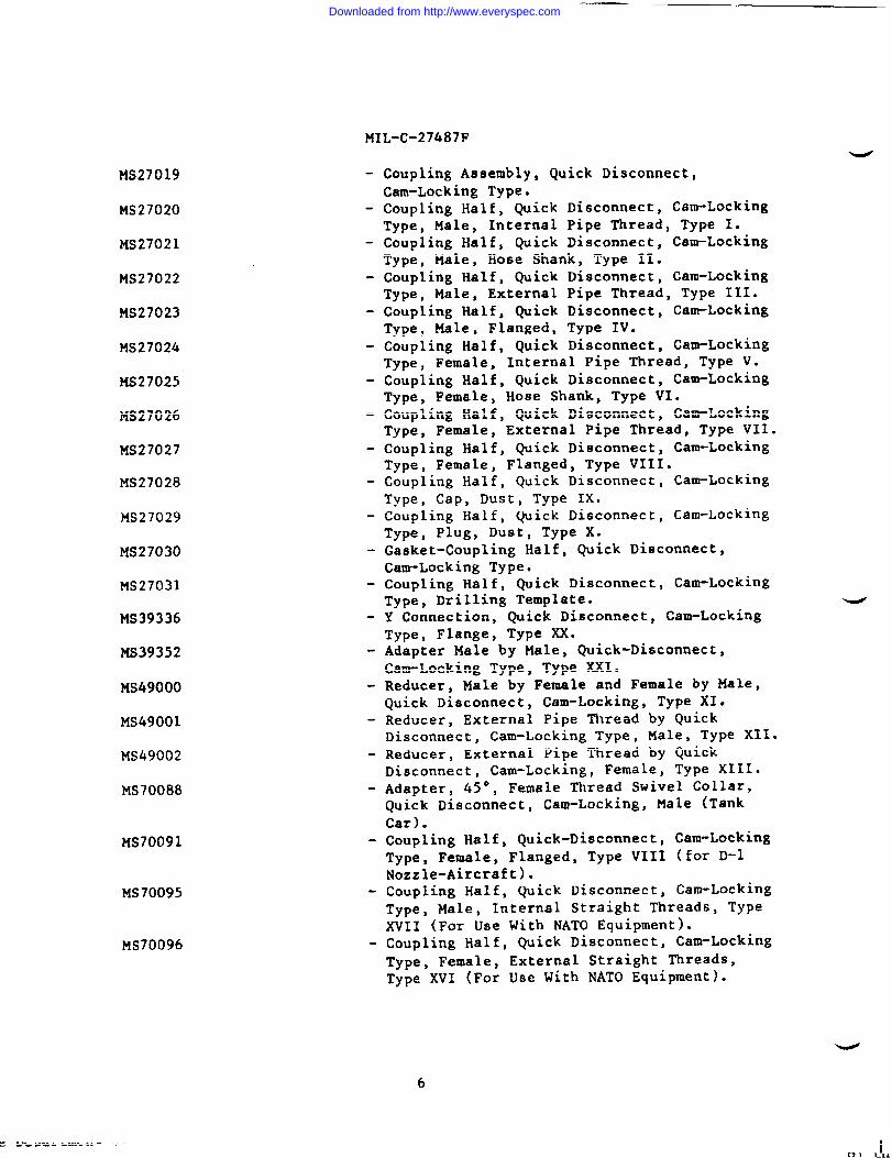
- Coupling Assembly, Quick Disconnect,Cam-Locking Type.
- Coupling Half, Quick Disconnect, Cam-LockingType, Male, Internal Pipe Thread, Type 1.
- Coupling Half, Quick Disconnect, Cam-LockingType, Male, Hose Shank, Type 11.
- Coupling Half, Quick Disconnect, Cam-LockingType, Male, External Pipe Thread, Type III.
- Coupling Half, Quick Disconnect, Cam-LockingType, Male, Flanged, Type IV.
- Coupling Half, Quick Disconnect, Cam-LockingType, Female, Internal Pipe Thread, Type V.
- Coupling Half, Quick Disconnect, Ca~-LockingType, Female, Hose Shank, Type VI.
- Coupling Half, Quick Disconnect, Cam-LockingType, Female, External Pipe Thread, Type VII.
- Coupling Half, Quick Disconnect, Cam-LockingType, Female, Flanged, Type VIII.
- Coupling Half, Quick Disconnect, Cam-LockingType, Cap, Dust, Type IX.
- Coupling Half, Quick Disconnect, Cam-LockingType, Plug, Dust, Type X.
- Gasket-Coupling Half, Quick Disconnect,Cam-Locking Type.
- Coupling Half, Quick Disconnect, Cam-LockingType, Drilling Template.
- Y Connection, Quick Disconnect, Cam-LockingType, Flange, Type XX.
- Adapter Male by Male, Quick-Disconnect,Cam-Locking Type, Type XXI.Reducer, Male by Female and Female by Male,Quick Disconnect, Cam-Locking, Type XI.
- Reducer, External Pipe Thread by QuickDisconnect, Cam-Locking Type, Male, Type XII*
- Reducer, External Pipe Thread by QuickDisconnect, Cam-Locking, Female, Type XIII*Adapter, 45°, Female Thread Swivel Collar,Quick Disconnect, Cam-Locking, Male (TankCar).
- Coupling Half, Quick-Disconnect, Cam-LockingType, Female, Flanged, Type VIII (for D-lNozzle-Aircraft).
- Coupling Half, Quick Disconnect, Cam-LockingTypej Male, Internal Straight Threads, TypeXVII (For Use With NATO Equipment).
- Coupling Half, Quick Disconnect, Cam-Locking
Type, Female, External Straight Threads,Type XVI (For Use With NATO Equipment)”
c UGV9L b.n-... -- —-
Downloaded from http://www.everyspec.com

MIL-c-27487F
MS70097 - Coupling Half, Quick Di8COnnt2Ct, Cam-LockingType, Female Reducer (Internal Pipe Thread),Type XVIII.
MS701OO - Coupling Half, Quick Disconnect, Cam-LockingType, Nipple Adapter, Male by ExternalGrooved Pipe, Type XIX.
(Copies of specifications and standards required by contractors in connectionwith specific acquisition functions should be obtained from the contractingactivity or as directed by the contracting activity.)
2.2 Other publications, The following documents form a part of thisspecification to the extent specified herein. Unless otherwise specified, theissues of the documents which are DOD adopted shall be those listed in the issueof the DoDISS specified in the solicitation. Unless otherwise specified, theissues of documents not listed in the DoDISS shall be the issue of thenon-Government documents which is current on the date of the solicitation.
AMERICAN NATIONAL STANDARDS INSTITUTE (ANSI)
B46.1 - Surface Texture.
(Application for copies should be addressed to the American National Standards
Institute, Inc., 1430 Broadway, New York, NY 10018.)
AMERICAN SOCIETY FOR TESTING AND MATERIALS (ASTM)
D 3951 - Standard Practice for Commercial Packaging.E18- Tests for Rockwell Hardness and Rockwell Superficial Hardness of
Metallic Materials.
(Application for copies should be addressed to the merican Society forTesting and Materials, 1916 Race Street, Philadelphia, pA 19103.)
(Non-Government standards and other publications are normally available fromthe organizations which prepare or which distribute the documents. Thesedocuments also may be available in or through libraries or other informationalservices.)
2.3 Order of precedence. In the event of a conflict betweenspecification and the references cited herein, the text of thisshall take precedence. Nothing in this specification, however,applicable laws and regulations unless a specific exemption has
3. REQUIREMENTS
the text of this
specificationshall supersedebeen obtained.
3.1 Description. me coupling halves, quick-disconnect, cam-locking type(hereinafter called “coupling(s)”) shall be in accordance with mi~itarYstandards as applicable, and shall consist of coupling body, wire rings, cam
arms, and gasket(s), as specified herein.
3.2 First article. Unless otherwise specified (see 6.2), a sample shall besubjected to first article inspection (see 4.3 and 6.3). Any changes or
7
—-—--—=—==—=____—.._._.=—___._—_-_=_._-=.—=_===—==>==_=.._=____—— .
Downloaded from http://www.everyspec.com

HZL-C-27487F
deviations of couplings halves from the approved first article during productionwill be subject to the approval of the contracting officer. Approval of thefirst article will not relieve the contractor of his obligation to furnishcoupling halves conforming to this specification.
3.3 Material. Material shall be as specified herein and as shown on theapplicable standards. Materials not specified shall be selected by thecontractor and shall be subject to all provisions of this specification.
3.3.1 Material deterioration prevention and control. fie couplings shall befabricated from compatible materials, inherently corrosion resistant or treatedto provide protection against the various forms of corrosion and deteriorationthat may be encountered in any of the applicable operation and storage environ-
ments to which the coupling may be exposed.
3.3.2 Dissimilar metals. Dissimilar metals shall not be used in intimatecontact with each other unless protected against galvanic corrosion. Dissimilarmetals and methods of protection are defined and detailed in MIL-STD-889.
3.3.3 Identification of materials and finishes. The contractor shall
identify the specific material, material finish or treatment for use withcomponent and subcomponent and shall make information available upon request tothe contracting officer or designated representative.
3.3.4 Recovered ❑aterials. For the purpose of this requirement, recoveredmaterials are those materials which have been collected from solid waste andreprocessed to become a source of raw materials, as distinguished from virginraw materials. The components, pieces and parts incorporated in the couplingsmay be newly fabricated from recovered materials to the maximum extentpracticable, provided the couplings produced meets all other requirements ofthis specification. Used, rebuilt or remanufactured components, pieces andparts shall not be incorporated in the couplings.
3.4 Construction.
3.4.1 Male couplings. Male couplings shall be fabricated to the dimensionsand tolerances specified on applicable standards (see 1.2). After fabrication,male couplings shall not leak or distort when hydrostatically tested as specifiedherein and on applicable standards (see 1.2).
%1 7.P A “ -..-...
3.4.2 Female couplings. Female couplings shall mate with the male coupling
gage specified herein. t?hen tested as specified herein, the torque required tocompletely close each cam arm and amount of gasket compression shall be inaccordance with the values specified in table I. Female couplings, completewith gaskets, shall not leak or distort and the cam arms shall not visually showmovement toward the unlocking direction when hydrostatically tested as specifiedherein and on applicable standards (see 1.2).
8
Downloaded from http://www.everyspec.com

MIL-C-27487F
TABLE 1. Torque values.
Coupling,
Maximum allowable Minimum gasketsize torque-to-close compression
(inch) (inch-pound) (inch)
1/2 and 3/4 60 0.0301 70 0.0301-1/4 to 2-1/2 100 0.0303 115 0.0254 130 0.0256 200 0.025
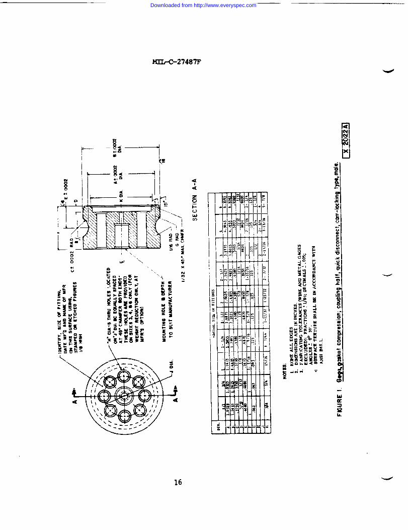
3.4.3 Male gage for gasket compression. A gage for each size female couplingshall be fabricated of steel, and shall have a hardness from 60 to 65 Rockwell Cwhen tested as specified herein, and shall conform to the dimensions and
tolerances specified in figure 1.
3.5 Safety. Unless otherwise specified herein and on applicable standards(see 1.2), nonfunctional sharp edges, projecting points, and excessive length offastening devices shall be avoided.
3.6 Identification marking. The couplings shall be legibly marked by eithercasting, die-stamping or embossing, stenciling, or by attaching an aluminum tagnot less than 0.03 inch in thickness by a soft annealed wire. The marking shallinclude the symbol MS,. standard number and dash number, the manufacturer’s
widentification, and size.
3.7 Interchangeability. All parts having the same part number of any singletype, size, and class coupling shall be functionally and dimensionally interchange-able. Interchangeable parts are defined as two or more like parts possessing suchfunctional and physical characteristics as to be equivalent in performance anddurability, and capable of being exchanged one for the other without alterationof the parts themselves or of adjoining parts, except for adjustment, and withoutselection for fit or performance.
3.8 Finish. Class 1, class 2, and class 3 couplings shall be finished as
specified on applicable standards (see 1.2).
3.9 Workmanship. All parts, components, and assemblies of the couplings,including castings, forgings, stampings, and machined surfaces, shall be cleanand free from sand, dirt, pits, sprues, scale, and other harmful extraneousmaterial. External surfaces shall be free from burrs, sharp edges, and corners,except where sharp edges and corners are required.
3.9.1 Castings. Castings shall be sound and free from blowholes, patching,
misplaced coring, warping, and any other defects which might render the castingsunsound or unsuitable for their intended use.
3.9.2 Machining. Tolerances and gages for interface fits shall conform tothe limitations specified herein and on applicable standards (see 1.2).
9
‘J
Downloaded from http://www.everyspec.com
MIL-C-27487F
3.9.3 Threads. Threads shall be as specified on the applicable standards (see
1.2).
3.9.4 Cleaning. The couplings shall be thoroughly cleaned of all machiningoil, residue of tests, grease, dirt, metal shavings and filings, and othercontaminants. Cleaning shall be accomplished in a manner that will not leave aresidue or otherwise render the couplings unsuitable for use.
4. QUALITY ASSURANCE PROVISIONS
4.1 Responsibility for inspection. Unless otherwise specified in the contractor purchase order, the contractor is responsible for the performance of allinspection requirements as specified herein. Except as otherwise specified inthe contract or purchase order, the contractor may use his own or any otherfacilities suitable for the performance of the inspection requirements speci-fied herein, unless disapproved by the Government. The Government reserves theright to perform any of the inspections set forth in the specification where such
inspections are deemed necessary to assure supplies and services conform toprescribed requirements.
4.1.1 Responsibility for compliance. All items must meet all requirements ofsections 3 and 5. The inspection set forth in this specification shall become apart of the contractor’s overall inspection system or quality program. Theabsence of any inspection requirements in the specification shall not relieve thecontractor of the responsibility of assuring that all products or suppliessubmitted to the Government for acceptance comply with all requirements of thecontract. Sampling in quality conformance does not authorize submission of knowndefective material, either indicated or actual, nor does it commit the Governmentto acceptance of defective material.
4.1.2 Component and material inspection. The contractor is responsible for
insuring that components and materials are manufactured, examined and tested inaccordance with referenced specifications and standards, as applicable.
4.2 Classification of inspections. The inspection requirements specifiedherein are classified as follows:
a. First article inspection (see 4.3).b. Quality conformance inspection (see 4.4).c. Inspection of packaging (see 4.6).
4.3 First article inspection.
4.3.1 Examination. The first article couplings shall be examined as specifiedin 4.5.1. Presence of one or more defects shall be cause for rejection.
4.3.1.1 Inspection conditions. Unless otherwise specified in a test, test
instruments , coupling parts, and other devices used in dimensioning, gaging, andperformance testing shall be stabilized at, and used in, an ambient temperatureof 75 “F, +15 ‘F. -
10
l.T1no [an IJII.%L . Lvuc LA ●
Downloaded from http://www.everyspec.com

uIL-C-27487F
4.3.2 Tests.
4.3.2.1 Gages.
4.3.2.1.1 Hardness. Gages shall be tested for hardness as specified in
4.5.2.1.1. Failure of the test shall be cause for rejection.
4.3.2.1.2 Accuracy. Gages shall be tested for accuracy as specified in4.5.2.1.2. Failure of the test shall be cause for rejection.
4.3.2.2 Couplings. The first article female and male couplings shall betested as specified in 4.5.2.2 and 4.5.2.3 using the gage(s) that havesuccessfully completed the tests specified in 4.3.2.1. Failure of either test
shall be cause for rejection.
4.4 Quality conformance inspection.
4.4.1 Samplin~. Sampling for examination shall be in accordance withMIL-STD-105.
4.4.2 Examination.
4.4.2.1 Individual. Each coupling shall be examined for the critical defects
specified in 4.5.1. presence of a critical defect shall be cause for rejection.
4.4.2.2 Samples. Samples selected in accordance with 4.4.1 shall be examinedfor the major and minor defects specified in 4.5.1. AQL shall be 1.0 percentdefective fo,rmajor defects and 6.5 percent defective for minor defects.
4.4.3 Tests.
4.4.3.1 Individual. Each female coupling shall be tested as specified in4.5.2.2 and 4.5.2.3. Each male coupling shall be tested as specified in4.5.2.3. Failure of any test shall be cause for rejection.
4.S Inspection procedure.
4.5.1 Examination. The couplings shall be examined as specified herein for
the following defects:
Critical
1. Evidence of blowholes, or pits in castings, which would render partunsound or unsuitable.
2. Noncompliance to interchangeability.
*
101. Material not as specified.102, Materials are not resistant to corrosion or deterioration or treated
to be made resistant to corrosion or deterioration for the applicablestorage and operating environment.
11
. — — . .
Downloaded from http://www.everyspec.com
MIL-C-27487F
1030
104.
1050
106.107●
108.109.110.111.
Minor
Dissimilar metals as defined in MIL-STD-889 are not effectivelyinsulated from each other.Contractor does not have documentation available for identificationof material, material finishes or treatmentsUsed, rebuilt, or remanufactured components, pieces, or partsincorporated in the coupling halves,Dimensions and tolerances not as specified.Gage(s) not as specified.Gasket(s) not as specified.Fasteners (cam arms) not functioning or not functioning properly.Noncompliance to environmental conditions.Threads not as specified.
2010202.
203.
204.205.
Noncompliance to safety conditions.Identification or special marking missing, illegible, misleading orincomplete.Treatment, painting, or finish not as specified on the applicable
standard.Cleaning not as specified.Workmanship not as specified.
4.5.2 Tests.
4.5.2.1 Gages.
4.5.2.1.1 Hardness. The hardness test method shall be conducted in accordancewith the applicable requirements of ASTM E 18. Indentations shall be made on theend face or flat surface of the gage. Three equally spaced indentations,approximately 1/8 inch in from the gage outside diameter, shall be made on eachend surface. Nonconformance to 3.4.3 shall constitute failure of this test.
4.5.2.1.2 Accuracy. Each dimension of each gage shall be verified by means ofcalibrated instruments with the applicable dimensions and tolerances specified onfigure 1. Nonconformance to figure 1 shall constitute failure of this test. The
furnishing of a written certification from an independent laboratory that the
gage(s) conforms to figure 1 may be accepted by the contracting officer in lieuof the above verification (see 6-2)0
4.5.2.2 Closing torque and gasket compression test procedure, femalecouplings. The female coupling shall be washed of any residual lubricant anddried prior to being coupled with the gage specified in 3.4.3. The coupling and
measurement of coupling action and gasket compression shall be as follows:
a. After insertion of the male gage into the female coupling to the maximumpenetration without using the cam arms or any other gasket compressionforce, measurement shall be made of the distance from the outside end ofthe male gage shown in figure 1, to the insertion end of the female
coupling at three points spaced equidistant around the face circumference.
The average distance shall be computed to the nearest thousandth of aninch.
12
.
Downloaded from http://www.everyspec.com

b.
c.
MIL-C-27487F
After insertion to the maximum penetration, each female coupling cam-arm
shall be subjected to a closing torque. This closing torque shall beapplied simultaneously to each cam arm and shall be sufficient to
completely close the female coupling over the male gage. Measure themaximum closing torque during the closing movement of each cam arm.
Closing torque in excess of the maximum allowable torque specified intable I shall constitute failure of this test.When the cam arms are completely closed, measurement shall again be madeas in “a”, and the average distance computed to the nearest thousandth of
an inch. This average distance shall be deducted from the averagedistance computed in “a”. The resultant difference is representative of
the amount of gasket compression. Nonconformance to table I shallconstitute failure of this test.
4.5.2.3 Hydrostatic. The male and female coupling shall be subjected to aninternal hydrostatic pressure as specified on applicable standards (see 1.2).The hydrostatic pressure shall be sustained for not less than 45 seconds.Gaskets shall be in place during testing of female couplings. The fluid used for
the test shall be distinctly dyed to facilitate visual examination for leakage.Evidence of leakage, distortion, or movement of cam arms shall constitute failure
of this test.
4.6 Inspection of packaging.
4.6.1 Military. Preservation, packing, and marking for military levelS Of
protection shall be examined to determine compliance with the quality assuranceprovisions of MIL-P-7750
4.6.2 Commercial. Preservation, packing, and marking for commercial degree of
protection shall be examined for compliance with ASTM D 39S1.
5. PACKAGING
5.1 Preservation. Preservation shall be level A or commercial, as specified
(see 6.2).
5.1.1 Level A. Couplings shall be preserved in accordance with the level Apreservation and packaging requirements of MIL-P-77S.
5.1.2 Commercial. Couplings shall be preserved in accordance with ASTM D 3951.
5.2 Packing. Packing shall be level A, level B, or commercial, as specified(see 6.2).
5.2.1 Level A. Couplings, preserved as specified in 5.1, shall be packed inaccordanc~the level A packing requirements of MIL-P-775.
5.2.2 Level B. Couplings, preserved as specified in 5.1, shall be packed inaccordanc~the level B-packing requirements of MIL-P-77S. Closure offiberboard boxes for level B-packing shall be in accordance with method V closurerequirements of PPP-B-636.
13
Downloaded from http://www.everyspec.com

MIL-C-27487F
5.2.3 Commercial. Couplings, preserved as specified in 5.1, shall be packed
in accordance with ASTM D 3951.
5.3 Marking.
5.3.1 Military. Marking for military levels of protection shall be inaccordance with MIL-STD-129.
5.3.2 Commercial. Marking for commercial degree of protection shall be inaccordance with ASTM D 39S1.
6. NOTES
6.1 Intended use. The quick-disconnect couplings covered by thisspecification are primarily used in suction hose, discharge hose, and nozzles
for various fittings or manifolds for handling of liquid petroleum products.
6.2
a.b.c.
d.
e.
f.
6.3should
Ordering data. Procurement documents should specify the following:
Title, number, and date of this specification.Military standard part number required (see 1.2 and applicable MS)*Time frame required for submission of first article couplings and numberof couplings required (see 3.2).When the Government will conduct any or all of the first article modelexamination and tests. When the Government will conduct some but not allof the first article examination and tests, the contracting officershould specify which examination and test will be conducted by theGovernment and which examination and tests shall be conducted by thecontractor (see 3.2).When certification will be accepted in lieu of verification (see4.5.2.1.2).Degree of preservation and degree of packing required (see 5-1 and 5s2).
First article. When a first article inspection is required, the itemsbe initial production. The first article should consist of one or more
couplings. The co~tracting officer should include specific instructions inacquisition. documents regarding arrangements for examinations, tests, andapproval of the first article test results and disposition of the first article.
6.4 International standardization. Certain provisions of this specification
and referenced standards (see 1.2) are the subject of international standardiza-tion agreement (QSTAG 240 and STANAG 2761). When amendment, revision, orcancellation of this specification is proposed which affects or violates theinternational agreement concerned, the preparing activity will take appropriatereconciliation action through international standardization channels, including
departmental standardization offices, if requiredc
6.5 Classification change. Type XIV, Y Connection, MS49003, with all sizes
and classes has been deleted as no longer required.
u
Downloaded from http://www.everyspec.com

MIL-C-27487F
6.6 Sub~ect term (Key word) Iistin&a
Coupling, quick disconnectcoupling, ha~vesFue 1, transport ofWater, transport of
6.7 Changes from previous issue. Asterisks (or vertical lines) are not used
in this revision to identify changes with respect to the previous issue due tothe extensiveness of the changes.
Custodians: Preparing activity:
Army - ME Amy - ME
Navy - YDAir Force - 99 Project 4730-0778
Review activities:Army - AV, GLAir Force - 82DLA - Cs
User activity:Army - ATNavy - MC
15
*“”. ---..=.. – .
Downloaded from http://www.everyspec.com
1
II
--27487F
●I
u
\
I -,
d ‘\\ow
~...
\
“4
s●
m●
x
Nm\
Downloaded from http://www.everyspec.com

INSTRUCTIONS: In s continuing●ffort to make our etanderdiition documenti Imt*r, theDoD prddeatbbform for uaein*tting commentsand ●gge@ione for improvement. All usersof miMaryatandardktion documents are invhd to provide
~tione. Tbh formmay bedetache~foldedalongtheUneeindicA@d,tapedalongtboboaeodg.(~ NOT STZ=), andtiled.inblock 5, be ae specificas ~ldc ●bout particularproblemareaosuchaswordingwhich requiredinterpretation,-too ri~d. mtfictiwe. loose. anb@ouq orwasincompatible,and~vepmpoeedwordingchangeowhichwouldalletitetbeproblenw. Enter in block 6 any remarks not relatedto ● specifiiparagraphof thedocument.lfblock 7 is filled out, en
●cknowledgementwillberndedtoyouwithin30 daystoIetyouknow thatyourcommenteuerwreceivedendue bebgconsidered.
NOTE: ‘I’M formmay notbeueed to reqwet copies ofdocuments,nortorequestdvere,d~tions,orcltificatbonof
8pecific8tion requirements on ourrent contmcts. Commente submittedon thbfomndo motconstituteorimply●uthodzationtowaiveanyportionofthereferenceddocument(s)or toamendcontractualrequimnente.
(Fohf dom thto U-)
(Fold along thk ltne)
DEPARTMENT OF THE ARMY
111111IINO ●OSTAGENECES8~RYIF MAtLSD
W TMEUNITEO STATES
b
OFFtCIAL WSINES●ENALTY FOR PRIVATE USE $300 BUSINESS REPLY MAIL
FIRST CLASS PERMIT NO. 120S2 WASHINGTON 0. C4 +POSTAGE WILL BE PAID BY THE DEPARTMENT OF THE ARMY
CommanderUS Army Mobility Equipment Research & Development
CommandATTN : DRDME-DSFort Belvoir, VA 22060
Downloaded from http://www.everyspec.com

STANDARDIZATION DOCUMENT IMPROVEMENT PROPOSAL(See hutPuctbu - Reverse Side)
DOCUMENT NUMBER 2. DOCUMENT TITLE
L NAME OF SUBMITYINO ORGANIZATION 4. TVPE OF ORGANIZATION (Md O18C)
•1VENOOR
, c1USER
AODRESS(Stiet, City, State, 21P Code)
c1MANUFACTURER
•1OTHER fsXCfh’).’ .,
, PROBLEM AREAS
a P.rcgroph Nt#mbor ●d Wording:
b.Rocommondod Wording:
c. FtMson/R@t(onslc for Rocommondmion:
i. REMARKS
~a.NAME OF SUBMITTER &sl, Fht, Ml) - Optional b. WO~K T6 LEPHONE NUM@G~ {hcludc AreaC*) - Optlono!
:, MAILING ADDRESS (Stmcf, City, Scote, ZfP Cotk) - OPthmd 8. DATE OF SUOMISStON (YYMMDD)
-- .&-
Uu s%:,1426-_——s..I_.-I__=_—-___—_._—_._.>...- .. _
PREViOUS EDITiON iS ~SOLETE.
— — —_ L—_.-—=__.-_._.__—__._.—__~__
Downloaded from http://www.everyspec.com