CALTRANS POST EARTHQUAKE INVESTIGATION PAST PRESENT … · CALTRANS POST EARTHQUAKE INVESTIGATION ....
14
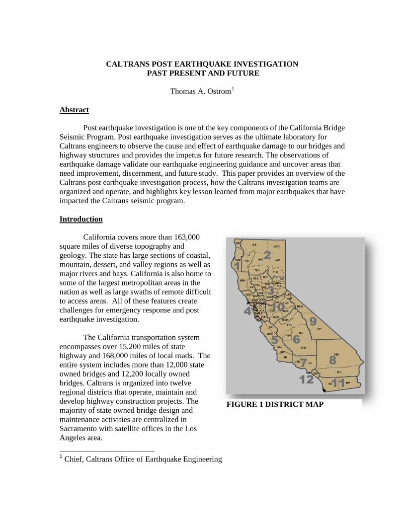
CALTRANS POST EARTHQUAKE INVESTIGATION PAST PRESENT AND FUTURE Thomas A. Ostrom 1 Abstract Post earthquake investigation is one of the key components of the California Bridge Seismic Program. Post earthquake investigation serves as the ultimate laboratory for Caltrans engineers to observe the cause and effect of earthquake damage to our bridges and highway structures and provides the impetus for future research. The observations of earthquake damage validate our earthquake engineering guidance and uncover areas that need improvement, discernment, and future study. This paper provides an overview of the Caltrans post earthquake investigation process, how the Caltrans investigation teams are organized and operate, and highlights key lesson learned from major earthquakes that have impacted the Caltrans seismic program. Introduction California covers more than 163,000 square miles of diverse topography and geology. The state has large sections of coastal, mountain, dessert, and valley regions as well as major rivers and bays. California is also home to some of the largest metropolitan areas in the nation as well as large swaths of remote difficult to access areas. All of these features create challenges for emergency response and post earthquake investigation. The California transportation system encompasses over 15,200 miles of state highway and 168,000 miles of local roads. The entire system includes more than 12,000 state owned bridges and 12,200 locally owned bridges. Caltrans is organized into twelve regional districts that operate, maintain and develop highway construction projects. The majority of state owned bridge design and maintenance activities are centralized in Sacramento with satellite offices in the Los Angeles area. 1 Chief, Caltrans Office of Earthquake Engineering FIGURE 1 DISTRICT MAP
Transcript of CALTRANS POST EARTHQUAKE INVESTIGATION PAST PRESENT … · CALTRANS POST EARTHQUAKE INVESTIGATION ....
CALTRANS POST EARTHQUAKE INVESTIGATION PAST PRESENT AND FUTURE
Thomas A. Ostrom1
Abstract Post earthquake investigation is one of the key components of the California Bridge Seismic Program. Post earthquake investigation serves as the ultimate laboratory for Caltrans engineers to observe the cause and effect of earthquake damage to our bridges and highway structures and provides the impetus for future research. The observations of earthquake damage validate our earthquake engineering guidance and uncover areas that need improvement, discernment, and future study. This paper provides an overview of the Caltrans post earthquake investigation process, how the Caltrans investigation teams are organized and operate, and highlights key lesson learned from major earthquakes that have impacted the Caltrans seismic program. Introduction California covers more than 163,000 square miles of diverse topography and geology. The state has large sections of coastal, mountain, dessert, and valley regions as well as major rivers and bays. California is also home to some of the largest metropolitan areas in the nation as well as large swaths of remote difficult to access areas. All of these features create challenges for emergency response and post earthquake investigation. The California transportation system encompasses over 15,200 miles of state highway and 168,000 miles of local roads. The entire system includes more than 12,000 state owned bridges and 12,200 locally owned bridges. Caltrans is organized into twelve regional districts that operate, maintain and develop highway construction projects. The majority of state owned bridge design and maintenance activities are centralized in Sacramento with satellite offices in the Los Angeles area. 1 Chief, Caltrans Office of Earthquake Engineering
FIGURE 1 DISTRICT MAP

Post Earthquake Investigation
The Caltrans Structure Maintenance and Investigation (SMI) unit is the primary responder for all bridge emergencies on the State Highway system. SMI is supported by the Offices of Bridge Construction (~700 engineers) and Structure Design (~400 engineers) as needed. Typically construction engineering is first on sight since Caltrans construction staff is dispersed statewide. During large level emergencies, SMI often requests bridge designers to augment their inspection teams to assist in triaging the damage and assisting in developing initial restoration strategies. The Office of Earthquake Engineering is responsible for conducting post earthquake investigations.
The mission of the Post Earthquake Investigation Team (PEQIT) is to gather information about the performance of bridges and other highway structures after large earthquakes. The information is used to evaluate Caltrans’ current bridge design and retrofit procedures. Caltrans currently has a roster of twenty engineers and geologists who have volunteered to participate in post earthquake investigations, gather information on the performance of bridges, and write reports on their findings.
The first earthquake to severely damage the California state highway system was the 1971 San Fernando Earthquake. It was the first time Caltrans send out a PEQIT. In fact the process that was followed in investigating the San Fernando Earthquake is still the model we use today for mobilizing, observing and disseminating the conclusions and recommendations of our earthquake investigations. The 1971 EQ damage was centered in the north easterly portion of the San Fernando Valley approximately 400 miles south of Sacramento. Much of the damage occurred to bridges that were under construction or recently finished. Several bridge contractors were literally “on location” which in turn led to rapid response, mobilization of heavy equipment and rapid demolition and shoring. The response to San Fernando spawned a philosophy within Caltrans that once public safety secured, rapid demolition and restoration of the system is our highest priority. This necessitates rapid deployment of investigation teams to observe and gather evidence before it is literally swept away.
FIGURE 2 SAN FERNANDO INVESTIGATION

Post Incident Investigation Team Procedures The PEQIT is managed by a coordinator. The coordinator is one of four individuals within Caltrans that carries a California Geologic Survey Strong Motion Instrumentation pager that provides magnitude and location of the ground shaking. An additional means of notification is ShakeCast; an email based application that couples USGS ShakeMap earthquake shaking data with bridge locations and fragility and generates bridge damage assessment maps. Generally no action is taken on earthquakes with magnitude below 5.0 and typically investigations are not mobilized for earthquakes below magnitude 6.0. For EQ between magnitude 5.5 and 6.0 the coordinator notifies local maintenance personnel to determine if any damage has been observed or reported and action is taken accordingly.
FIGURE 3 SHAKECAST MAP

Once the geographical area of investigation is determined and damage reports are confirmed, instructions are uploaded to an automated hotline and PEQIT members are contacted to report to duty. A myriad of logistical steps must be done including; arranging for transportation (air or auto), equipment, lodging, and support such as California Highway Patrol escorts. For larger events multiple team are mobilized with one team member appointed as the lead. During large investigations, that may take several days, the coordinator communicates with all of the team leads and provides technical and logistical support. The coordinator is the link between the field teams and the Office of Emergency Services, the Caltrans Emergency Operations Center and the SMI Disaster Command Center. Other useful information included in the PEQIT manual is the contact information for all of the maintenance engineers, construction managers, and district dispatchers statewide. This information is updated biannually and provides a grab-and-go resource for field teams to locate contacts in the area of investigation. The local contacts are essential to locate damaged structures and provide equipment and access. PEQIT members are predominantly design engineer volunteers. The team is make up is a balance of youth and experience to promote mentor based training and seamless succession planning. Check listss for all PEQIT roles and logistical information is located in the PEQIT manual. Personal Safety and Training The highway system is a dangerous place for pedestrians. This is magnified greatly in the post event environment. Investigators need to be cognizant of public traffic, aftershocks, and heavy equipment. Investigators often have to work dawn to dusk, navigate over debris, and travel large distances on foot. Investigators may also come in contact with hazardous material and distressed or deceased people or animals. Although PEQIT’s first priority is to collect perishable data, they may be the first person to find a severely damaged bridge and immediately must contact emergency authorities. Each investigator is responsible for having their personal equipment packed and ready (i.e. hard hat, boots, flash lights, cameras, rain gear, etc...). Water and food is provided by the coordinator when the team disembarks or is procured prior to entering the damage zone. Investigators are encouraged to stay current on CPR and confined space training.

Equipment The PEQIT still relies primarily on unaided visual observation and photographs to record their investigation. SMI and construction provide support to inaccessible areas via man lifts, snooper trucks, and boroscopes where available. See Figure 4. In the past investigators were provided climbing gear and training, this has been discontinued for personnel safety reasons.
FIGURE 4 SNOOPER BOOM TRUCK Instrumented Bridges Caltrans has collaborated with the California Geologic Survey to gather strong motion data. Currently there are 78 bridges instrumented including all of the California toll bridges and 29 geotechnical instrumentation arrays. Earthquake investigator are instruct to do an extra thorough job inspecting the instrumented bridges so we can study the relationship between bridge damage, ground shaking, and structural response.
EQ Primer The remainder of the PEQIT manual contains sections on the seismology of California, a photo log of previously observed bridge damage, a section on evaluating the performance of retrofitted bridges, and a photo log of column ductility tests. These sections aid the investigator as to what kind of damage to look for, provides insight into how retrofitted bridges are expected to perform and aid in assessing damage.
Implementation of PEQIT Recommendations The best way to evaluate the effectiveness of past Caltrans earthquake investigations is evident in how the recommendations and conclusions have been implemented. Below are a few of the many examples where recommendations and conclusions (bold) from the San Fernando and Northridge earthquake investigation reports have been directly incorporated into Caltrans’ design policies and practices (italics).
San Fernando Earthquake Conclusions and Recommendations 1. Minimize the number of hinges in superstructures, provide ample seat width and
be adequate tied to resistance to horizontal and vertical seismic forces
SDC 7.2.5.4 Hinge Seat Width for Frames Meeting the Requirements of Section 7.1.2 Enough hinge seat width shall be available to accommodate the anticipated thermal movement, prestress shortening, creep, shrinkage, and the relative longitudinal earthquake displacement demand between the two frames. The seat width normal to the centerline of bearing shall be calculated by Equation 7.2.5.4-1 but not less than 24 inches. See Figure 9.
inN eqtempshcrspH 4/ +∆+∆+∆+∆≥ + (7.2.5.4-1)
2. Tall and slender columns performed better than short stiff columns, however tall
slender columns permit larger displacement and framing consideration is vital to insure stability.
SDC 7.1.3 Adjusting Dynamic Characteristics The following list of techniques should be considered for adjusting the fundamental period of vibration and/or stiffness to satisfy Equations 7.1.1-1 to 7.1.1-4 See Figure 12. • Oversized pile shafts
• Adjust effective column lengths (i.e. lower footings, isolation casing)
• Modified end fixities
• Reduce/redistribute superstructure mass
• Vary the column cross section and longitudinal reinforcement ratios
• Add or relocate columns
• Modify the hinge/expansion joint layout
• Incorporate isolation bearings or dampers
A careful evaluation of the local ductility demands and capacities is required if project constraints make it impractical to satisfy the stiffness and structure period requirements.
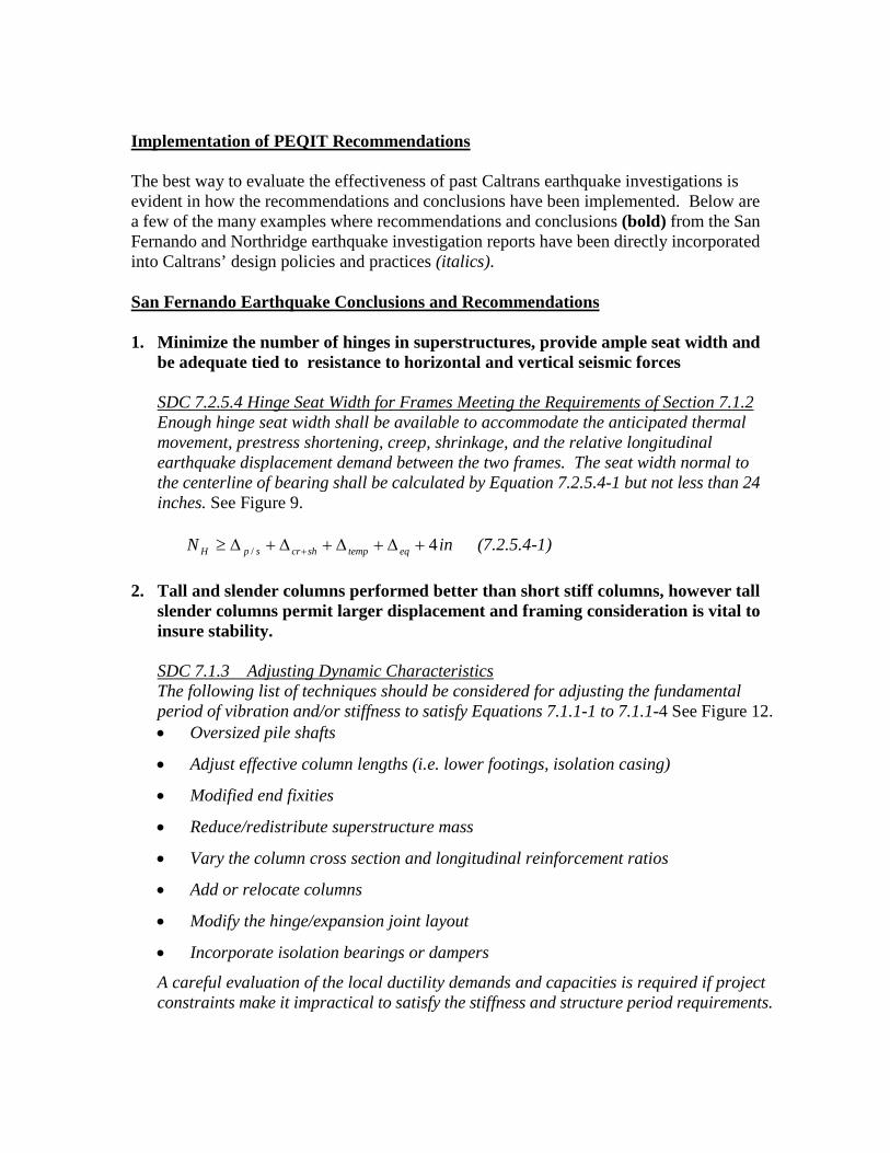
SDC 4.2 P-∆ Effects The dynamic effects of gravity loads acting through lateral displacements shall be included in the design. The magnitude of displacements associated with P-∆ effects can only be accurately captured with non-linear time history analysis. In lieu of such analysis, Equation 4.2-1 can be used to establish a conservative limit for lateral displacements induced by axial load for columns meeting the ductility demand limits specified in Section 2.2.4. If Equation 4.2-1 is satisfied, P-∆ effects can typically be ignored.
colprdl MΔP ×≤× 20.0 (4.2-1)
∆r = The relative lateral offset between the point of contra-flexure and the base of
the plastic hinge. For Type I shafts sDr ∆∆∆ −= s∆ = The shaft displacement at the point of maximum moment
FIGURE 5 SHORT COLUMN FIGURE 6 ISOLATION CASING FAILURE
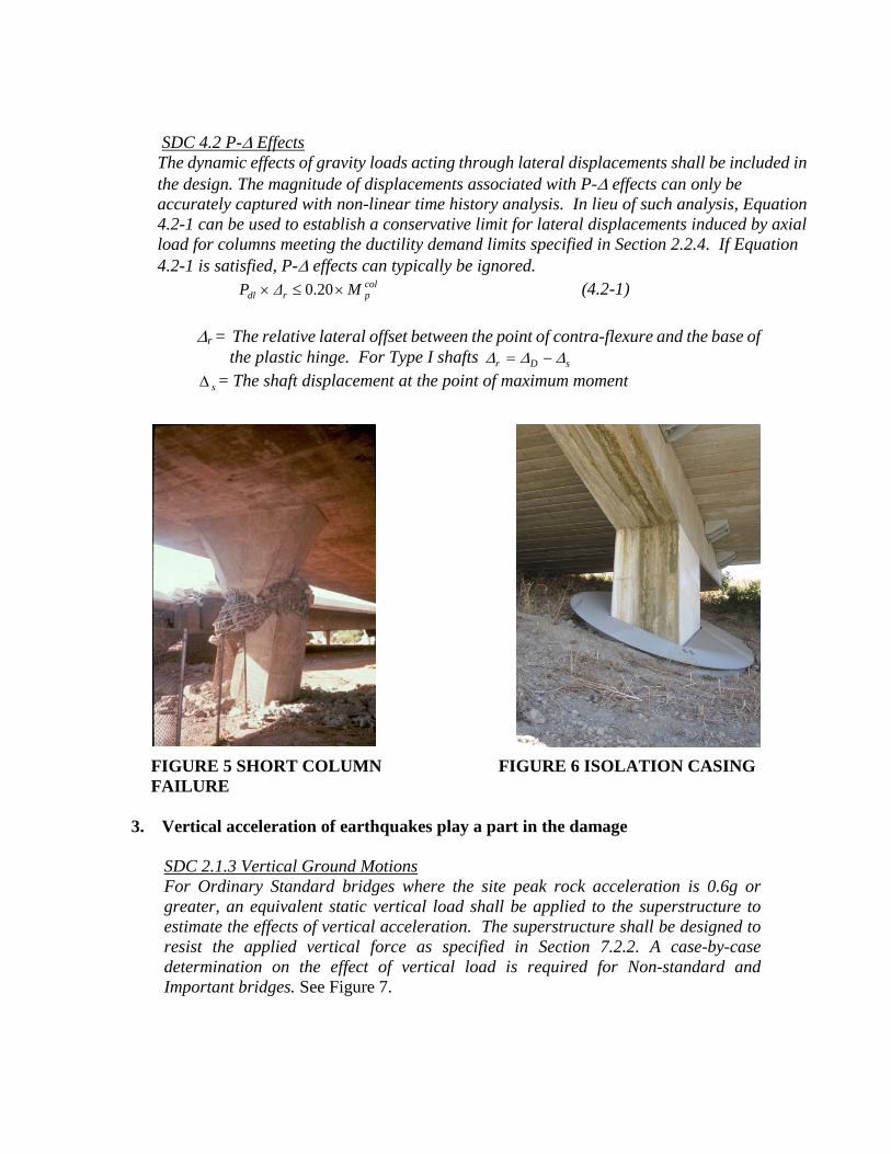
3. Vertical acceleration of earthquakes play a part in the damage
SDC 2.1.3 Vertical Ground Motions For Ordinary Standard bridges where the site peak rock acceleration is 0.6g or greater, an equivalent static vertical load shall be applied to the superstructure to estimate the effects of vertical acceleration. The superstructure shall be designed to resist the applied vertical force as specified in Section 7.2.2. A case-by-case determination on the effect of vertical load is required for Non-standard and Important bridges. See Figure 7.

FIGURE 7 EQUIVALENT STATIC FIGURE 9 MIN. SEAT LENGTH VERTICAL LOAD
4. Column ties should be increased at point of high stress, the use of spiral
reinforcement in column should be encouraged.
SDC 3.8.1 Lateral Reinforcement Inside the Analytical Plastic Hinge Length The volume of lateral reinforcement typically defined by the volumetric ratio, sρ provided inside the plastic hinge length shall be sufficient to ensure the column or pier wall meets the performance requirements in Section 4.1. The volumetric ratio, sρ for columns with circular or interlocking core sections is defined by Equation 3.8.1-1.
sD
Abs ′=
4ρ (3.8.1-1)
Equivalent Static Positive Vertical Load = (0.25 x DL)
Equivalent Positive Vertical Moment
Equivalent Static Negative Vertical Load = (0.25 x DL)
Equivalent Negative Vertical Moment
4” ∆ eq ∆ p/s + ∆ cr+sh + ∆ temp
24 in. Seat ≥
N
FIGURE 8 ISOLATION CASING

For rectangular columns with ties and cross ties, the corresponding equation for sρ , is:
sD
A
c
vs '=ρ (3.8.1-2)
vA = Sum of area of the ties and cross ties running in the direction perpendicular to the axis of bending
'cD = Confined column cross-section dimension, measured out to out of ties, in the
direction parallel to the axis of bending
FIGURE 10 UNCONFINED COLUMN FALURE- SAN FERNANDO
FIGURE 11 DUCTILE COLUMN TESTING

Northridge Earthquake Conclusions and Recommendations 1. Variation in stiffness from column to column and bent to bent should be kept to a
minimum
SDC 7.1.1 Balanced Stiffness It is strongly recommended that the ratio of effective stiffness between any two bents within a frame or between any two columns within a bent satisfy Equations 7.1.1-1 and 7.1.1-2. It is strongly recommended that the ratio of effective stiffness between adjacent bents within a frame or between adjacent columns within a bent satisfy Equations 7.1.1-3 and 7.1.1-4. An increase in superstructure mass along the length of the frame should be accompanied by a reasonable increase in column stiffness, see Figure 7.1.1-1. For variable width frames the tributary mass supported by each bent or column shall be included in the stiffness comparisons as specified by Equations 7.1.1-2 and 7.1.1-4. The simplified analytical technique for calculating frame capacity described in Section 5.5 is only permitted if either Equations 7.1.1-1 and 7.1.1-3 or Equations 7.1.1-2 and 7.1.1-4 are satisfied. The following considerations shall be taken into account when calculating effective stiffness: framing effects, end conditions, column height, percentage of longitudinal and transverse column steel, column diameter, and foundation flexibility. Some of the consequences of not meeting the relative stiffness recommendations defined by Equations 7.1.1-1 to 7.1.1-4 include:
• Increased damage in the stiffer elements
• An unbalanced distribution of inelastic response throughout the structure
• Increased column torsion generated by rigid body rotation of the superstructure
2. Effective moment of inertia should be respected in seismic analysis
SDC 5.6.1.1 Ieff for Ductile Members The cracked flexural stiffness Ieff should be used when modeling ductile elements. Ieff can be estimated by Figure 5.6.1.1-1 or the initial slope of the M-φ curve between the origin and the point designating the first reinforcing bar yield as defined by Equation 5.6.1.1-1. See Figure 13.
y
yeffc
MIE
φ=× (5.6.1.1-1)
yM = Moment capacity of the section at first yield of the reinforcing steel.

Column/Bent Stiffness Ratio for
Constant Width Frames
Variable Width Frames
For any 2 Bents in a frame
or any 2 Columns in a Bent
5.0≥ej
ei
kk (7.1.1-1)
5.02 ≥≥
j
ej
i
ei
mk
mk
(7.1.1-2)
For adjacent bents in a frame
or adjacent Columns in a Bent
75.0≥ej
ei
kk (7.1.1-3)
75.033.1 ≥≥
j
ej
i
ei
mk
mk
(7.1.1-4)
eik = The smaller effective bent or column stiffness mi = Tributary mass of column or bent i ejk = The larger effective bent or column stiffness mj = Tributary mass of column or bent j
FIGURE 12 SDC COLUMN/BENT STIFFNESS RATIOS FOR FRAMES
FIGURE 13 EFFECTIVE STIFFNESS OF CRACKED R/C SECTIONS

3. Flared column behavior under EQ loads should be investigated thoroughly for
both long and short columns especially their effects on predicted plastic hinge location SDC 7.6.5.1 Horizontally Isolated Column Flares The preferred method for detailing flares is to horizontally isolate the top of flared sections from the soffit of the cap beam. Isolating the flare allows the flexural hinge to form at the top of the column, minimizing the seismic shear demand on the column. The added mass and stiffness of the isolated flare typically can be ignored in the dynamic analysis.
A horizontal gap isolating the flare from the cap beam shall extend over the entire cross section of the flare excluding a core region equivalent to the prismatic column cross section. The gap shall be large enough so that it will not close during a seismic event. The gap thickness, G shall be based on the estimated ductility demand and corresponding plastic hinge rotation capacity. The minimum gap thickness shall be 4 inches. See Figures 14 & 15.
FIGURE 15 FLARE COLUMN DETAILS
FIGURE 14 FLARED COLUMN FAILURE

Future PEQIT Challenges and Opportunities It has been eighteen years since the Northridge Earthquake. Many of the Caltrans engineers who responded to the 1989 Loma Prieta and 1994 Northridge Earthquakes are nearing retirement or have moved into managerial position within Caltrans. The lack of recent significant seismic events inhibits real world on the job training for the next generation of investigators. Caltrans is addressing succession planning by better documenting our practices and lesson learned and mentoring younger staff. Caltrans has responded to several bridge fires, high load hits, bridge scour incidents, and fatigue induced failures in the last decade. These events have tested the Department’s emergency protocols and have led to improvements to how Caltrans responds during a bridge crisis such as earthquakes. The Caltrans seismic program competes with other pressing transportation safety initiatives and infrastructure needs in a severely constrained financial situation. In spite of dwindling budgets we continue to learn more and gather more data to forge our approach to earthquake engineering. We need to take advantage of technology that allows us to readily share information and work in partnership worldwide.
The lessons of tsunami recently in Japan, of fault ruptures and velocity pulse induced damage during earthquakes worldwide, have allowed Caltrans to make improvements before these hazards occur in California. Caltrans is working on the following topics to improve the effectiveness of our earthquake investigations
• Utilize mapping tools to document bridge damage identified by PEQIT • Use PEQIT lessons for Performance Based Seismic Design Criteria (PBSDC). • Improve ShakeCast Damage Assessments • Update Fragility Predictions • Determine effectiveness of isolation bearings and dampers. • Develop Predefined design solutions for typical earthquake damage. • Develop tools for Post-Earthquake Damage Assessment of Instrumented Bridges
Conclusion Post earthquake Investigation is an important component of the California Seismic
Program along with the seismic research, the development of California specific seismic design criteria and independent review from the Caltrans Seismic Advisory Board. Many of the progressive changes to Caltrans’ earthquake engineering philosophy and resulting policies and procedures can be directly attributed to the observations and recommendations from the investigation of earthquakes that have occurred in California since 1971. The clock continues to tick toward the next large earthquake and it is of paramount importance that Caltrans continues to staff and train its post earthquake investigation team. SEMPER PARATUS.

Acknowledgments
2012 marks the eighteenth year that Mark Yashinsky has served as the Caltrans PEQIT coordinator. I want to acknowledge Mark for his leadership and unbridled enthusiasm for investigating earthquakes around the globe.
References 1. Caltrans, The San Fernando Earthquake Field Investigation of Bridge Damage,
Sacramento CA. 1971 2. Caltrans, The Post Earthquake Investigation Team Report for the Loma Prieta
Earthquake Report, Sacramento CA. 1989 3. Caltrans, The Northridge Earthquake Post Earthquake Investigation Report,
Sacramento CA. 1994 4. Caltrans, Seismic Design Criteria version 1.6, Sacramento CA. 2010 5. Caltrans, Post Earthquake Investigation Team (PEQIT) Manual,
Sacramento CA. 2012