CALMA PUMP SERIES - HASMAK Pump_US_final082009.pdf · CALMA PUMP SERIES A NEW STANDARD FOR NOISE...
16
Outstanding Hydraulic Products, Service and Expertise, Worldwide CALMA PUMP SERIES A NEW STANDARD FOR NOISE REDUCTION HYDRAULIC SYSTEMS DIVISION NEW !
-
Upload
truongthuy -
Category
Documents
-
view
213 -
download
0
Transcript of CALMA PUMP SERIES - HASMAK Pump_US_final082009.pdf · CALMA PUMP SERIES A NEW STANDARD FOR NOISE...

Outstanding Hydraulic Products, Service and Expertise, Worldwide
CALMA PUMP SERIESA NEW STANDARD FOR NOISE REDUCTION
HYDRAULIC SYSTEMS DIVISION
NEW !

HALDEX-CALMA SERIES-US-2009-082
Gear FlankContact Line
Gear FlankContact Line
Standard Gear PumpSingle Flank Engagement
CALMA SeriesDouble Flank Engagement
Outlet Pressure Pulsationreduced by 75%vs. Standard Gear Pump
THE POWER OF CALMALow noise across a wide speed range
Haldex Hydraulics Systems is a specialist in hydraulic gear product technology. The company has a long standing tradition of developing gear products that meet the unique needs of specifi c markets and ap-plications. In the electric vehicle markets low noise operation across a wide speed range is a key require-ment. This capability enables operator comfort and improved control and positioning for various vehicle functions.
Haldex Hydraulics established itself as a leader in low noise gear products a decade ago when it introduced its WQ series (quiet) gear pump product line featuring dual fl ank engagement of the gear teeth to reduce the amplitude of the pressure pulsations introduced into the hydraulic system. The size of the pressure pulsation from the pump determines the pump noise levels.
Now Haldex is introducing the Calma Series which sets the new standard for low noise operation. Avail-able in displacements from 6.2cc – 23.7cc the Calma pump’s pressure pulsation is minimized to 25%. Calma’s effi ciency, wide speed range and low noise performance are the result of extensive research and development.
Calma is especially well suited to applications on electric counterbalanced lift trucks, warehouse lift trucks, electric aerial work platforms and other mobile equipment where low noise, low speed and high ef-fi ciency are required.
Pictures above are used with the kind permission of eg: Atlet, BT, Huddig, Scania, Toro and Volvo Construction Equipment.The right to modifi cations for technical improvements is reserved.
Calma Series vs. Traditional Gear Pump
Calma Pump Features: • 97% Typical Volumetric Effi ciency
• Wide Speed Range
• Substantial Noise Reduction
• Pressure Pulsation Reduced by 75%
• A newly engineered tooth geometry
• An innovative approach to gear fl ank engagement
• Reduced trapped oil volume
• Compares favorably with more expensive internal gear pumps on effi ciency and low noise operation

HALDEX-CALMA SERIES-US-2009-08 3
CALMA DESCRIPTION
The key performance features of Calma are its low noise operation over a wide speed range. Like its predecessor the WQ pump Calma is a three piece modular design. The pump body is manufactured from high strength aluminum alloy. The mounting fl ange and rear cover are of cast iron. The Calma pumps come in single or mul-tiple confi guration of up to four sections. For optimum strength, gears and shafts are precision machined in one piece. The 13-tooth gear geometry has been optimized for low noise level. All shaft bearing surfaces are Tefl on® coated and designed for long service life. They are continually cooled and lubricated by a controlled fl ow of fresh oil. This enables operation across a wide speed range at very high loads. Multiple pumps in the Calma range are very compact. The drive shaft is capable of transmitting high torque even to the rear section. Each section has its own inlet and pressure ports. Single inlet features are op-tional for 2 and 3 section units. A wide range of mounting fl anges and port sizes are available to meet international standards.
Operating pressure range
Inlet port: continuous, minimum -6 In. Hg.intermittent, minimum -10 In. Hg.maximum +29.0 In. Hg.Outlet port (See tables on pages 6-10)
Speed rangeMinimum speed for all pump sizes is n=500 rpm at maximum operating pressure. L (WSR) Wide op-erating speed range with low speed capability adds min. speed n=400 rpm at max. operating pressure. Maximum speed for single pumps depends on the pump model in question and can be identifi ed from tables on pages 6-9 for respective models.Maximum speed for multiple pumps is the low-est one specifi ed (See tables on pages 6-9) for any section of the confi guration in question.
Noise performance data according to page 5.
Hydraulic Fluids
The use of HL-or HLP-hydraulic oil according to DIN 51 524 is recommended.The permissible viscosity for all Calma pumps is from 59 to 3465 SSU (10 to 750 cSt). The recom-mended operating viscosity range is from 74 to 185 SSU (16 to 40 cSt). The permissible cold start viscosity is 9240 SSU (2000 cSt).We recommend you contact Haldex before using fi re resistant or bio-degradable fl uids.Viscosities (when operating at above temperature limits) have to remain within the range specifi ed under ”Hydraulic Fluids”.
Temperature range
Ambient temperature min. -13°F (-25°C) max. +176°F (+80°C)Fluid temperature continuous operation max. +194°F (+90°C)intermittent operation max. +221°F (+105°C)
Please note
Fluid cleanlinessFluid cleanliness according to ISO 4406/1999[-18/14]or better is required in order to assure the pump’s high level of effi ciency in the long term.
Drive arrangementFlexible couplings are preferred for direct drives. Please contact Haldex for indirect drive require-ments. Pumps with outboard side load bearing are available.
Mounting position
As required.
Symbols
Single pump
Double pump
Triple pump
Quadruple pump
PERFORMANCE DATA
General dataDisplacement (V) 0.378 - 1.446 in3/rev (6.2 - 23.7 cc/rev)Wide Speed Range (WSR) (n) 400 - 4000 rpmPressure Operating pressure (p2) max. 3625 psi (250 bar)Operating temperatures (t) max. 221°F (105°C)Typical volumetric effi ciency 97%The maximum values for n, p2 and t for a given pump specifi cation may be applied simultaneously.
Options
• Mounting fl anges - SAE, rectangular and through bolt.• Shafts - Tang, spline, tapered or straight with key.• Ports - Thread or fl ange.• Rotation - CW or CCW.• Integrated valves.• Single inlet for multiple units.
Model code example for a single pump
= Type
= Range = Design A - Std. Calma Design L - L (WSR)* = # of sections
= Seal material
= Displacement per section = Rotation
= Mounting fl ange
= Drive shaft
= Portings
= Valve options
Pressure pulsation reduced by 75 %
The size of pressure pulsation from the pumps is refl ected in the low pump noise level.
1 2 3 4 5 6 7 8 9 10 11
WK 09 A 1 B 060 R 03 BA 150 N
1
2
3
6
7
8
9
10
11
4
5
* L (WSR) Wide operating speed range with low speed capability n=400 rpm at max. operating pressure p2.

HALDEX-CALMA SERIES-US-2009-084
Permissable Pressure vs. Speed Capability
0
100
200
300
400
500
600
700
800
900
1000
1200
1400
1600
1800
2000
2200
2400
2600
2800
3000
0
725 / 50
1450 / 100
2175 / 150
2900 / 200
3625 / 250
4351 / 300
Pres
sure
[p
si /
bar
]
Speed [R.P.M.]
DesignCode“L”
DesignCode“A”
Design Code ”L”Calma WK9L (WSR Design)Wide operating speed range (WSR) offers low noise operation within the common operating speed range as well as additional low speed capability. This design incorporates additional side plates.
Size CodeDisplacementin/rev (cc/rev)
Operating Pressure (P2)
psi (bar)Max. Speed
rpmMin. Speed
rpm
060 0.378 (6.2) 3625 (250) 4000 400
080 0.506 (8.3) 3625 (250) 4000 400
110 0.689 (11.3) 3625 (250) 3600 400
140 0.884 (14.5) 3625 (250) 3300 400
160 1.006 (16.5) 3625 (250) 3000 400
190 1.196 (19.6) 3625 (250) 3000 400
230 1.446 (23.7) 3045 (210) 2800 400
- Operating pressure P2: max. 20 sec. loaded following 10 sec. minimum unloaded. Pressure rating at min. speed is max. 1450 psi / 100 bar (intermittent).- Operating pressure rating refers to fl anged port confi guration (3045 psi / 210 bar for threaded ports).- Viscosity: minimum 59 SSU (10 mm2/s)
- Wide Operating Speed feature (Design Code ”L”) offers reduced minimum speed. Valid at P2 operating pressure, max. 2.5 sec. load duration at 400 rpm. NOTE - Reduced operating pressure results in longer permissable load duration (> 2.5 sec.) and/or reduced speed < 400 rpm.
Calma Design - Two Versions
Design Code ”A”Calma WK9A (Standard Design)Standard design offers low noise operations within the common operating speed range.
Size CodeDisplacementin/rev (cc/rev)
Operating Pressure (P2)
psi (bar)Max. Speed
rpmMin. Speed
rpm
060 0.378 (6.2) 3625 (250) 4000 500
080 0.506 (8.3) 3625 (250) 4000 500
110 0.689 (11.3) 3625 (250) 3600 500
140 0.884 (14.5) 3625 (250) 3300 500
160 1.006 (16.5) 3625 (250) 3000 500
190 1.196 (19.6) 3625 (250) 3000 500
230 1.446 (23.7) 3045 (210) 2800 500
- Operating pressure P2: max. 20 sec. loaded following 10 sec. minimum unloaded. Pressure rating at min. speed is max. 1450 psi / 100 bar (intermittent).- Operating pressure rating refers to fl anged port confi guration (3045 psi / 210 bar for threaded ports).- Viscosity: minimum 59 SSU (10 mm2/s)
Haldex offers two different verisons of Calma pumps:
• Code Design “A” Calma WK9A. Standard design offers low noise operations within the common operating speed range.
• Code Design “L” Calma WK9L. Wide operating speed range offers low noise operation within the common operating speed range as well as additional low speed performance and effi ciency. The L option is ideally suited for applications like the steering idle mode on a electrical forklift truck. This design incorporates additional side plates.

HALDEX-CALMA SERIES-US-2009-08 5
Sound Comparison
Pump Displacement 0.689 in(WK9A-0.689 in / 11.3 cc)According to DIN 45635 T26
500 RPM 1000 RPM 1500 RPM 2000 RPM
55
60
65
70
75
80
36225
72550
1450100
2175150
2900200
3625250
P (psi)P (bar)
dB
(A)
60
65
70
75
80
85
dB
(A)
36225
72550
1450100
2175150
2900200
3625250
P (psi)P (bar)
Sou
nd
po
wer
leve
l in
L
d
B(A
)
Steer Tilt Lift
Original
CALMA - Series
Steer
Tilt
Lift0
10
20
30
40
50
60
70
80
WA
2 ton Electrical Forklift Truck
(Vehicle unloaded)
Pump Displacement 0.884 in3/rev(14.5 cc/rev)Measured in driver’s cab
CALMA Sound Power Level in LWA
Pump Displacement 1.196 in(WK9A-1.196 in / 19.6 cc)According to DIN 45635 T26
500 RPM 1000 RPM 1500 RPM 2000 RPM

HALDEX-CALMA SERIES-US-2009-086
24.123.7[.94][.93]
19.0519.02[.750][ 749]
Ø
18.317.9[.72][.71]
32.531.5[1.27][1.24]Note 1:(SEE ORDER CODE BA)
4.75 x 4.75 x 22.2[.187 x .187 x .875]KEY
32.531.5[1.27][1.24]Note 1:Dimension represents shaft extension for flange Options 03 & 05.
For Through Bolt Options 10 and 11, add 2.5 mm (.098 in.) to the min. &max. shaft extension shown.
26.325.9[1.03][1.01]
21.2320.97[.836][.826]
19.0519.02[.750][.749]
Ø
FLANGE CODE 03(SAE ”A” 2-BOLT)
106.4[4.189]
133[5.24] MAX.
INLET OUTLET
CLOCKWISEROTATION
11.3610.98[.447][.432]
Ø
32.0[1.26]
97[3.82]MAX.
Ø
R 12.0[.472]
For counterclockwise rotation,inlet and outlet are reversed.
82.5582.50[3.250][3.248]
Ø
11.711.3[.46][.44]
6.405.89[.252][.232]
13.5[.53]
16.0[.63]
YXMAX.
88[3.46]MAX.
107[4.21]MAX.
69.5[2.74]
R 12.3[.48]MIN.
SHAFT FA
SHAFT GA
SHAFT BA
SHAFT CA
17.7317.47[.698][.688]
15.8815.85[.625][.624]
Ø
32.531.5[1.27][1.24]Note 1:(SEE ORDERCODE BA)
24 2
3.97 x 3.97 x 19.05[.156 x .156 x .75]KEY
= Type WK - Calma Pump
= Range 09 - WK900 Series = Design A - Std. Calma Design L - L (WSR)* = # of sections 1 - Single 2 - Duplex 3 - Triplex 4 - Quadruplex
= Seal material B - Buna
= Displacement per section (See Code Displ. below) = Rotation R - Clockwise L - Counter clockwise
Model code example for a single pump
1 2 3 4 5 6 7 8 9 10 11
WK 09 A 1 B 080 R 03 FA 101 N
= Mounting fl ange 03 SAE A 2-Bolt = Drive shaft BA - SAE A Key Ø 0.75” CA - SAE A Key Ø 0.625” FA - SAE A Spline 9-Tooth GA - SAE A Spline 11-Tooth = Portings (see page 13) = Valve options N - None
All shaft options on pages 11 and 12 can be used with this fl angeoption. We have just shown the most commonly used shaft options on the left. Port options available, see page 13 for details.
1
2
3
4
5
6
7
8
9
10
11
Operating pressure P2 Maximum speed Dimensions** Weight
Size Displacement X max. Y (approx.)Code cc/rev in3/rev bar psi rpm mm [in] mm [in] kg [lbs]
060 - 6.2 0.378 250 3625 4000 92.7 [3.65] 44.0 [1.73] 3.6 [7.9] 080 - 8.3 0.506 250 3625 4000 95.0 [3.74] 45.5 [1.79] 3.7 [8.1]110 - 11.3 0.689 250 3625 3600 100.1 [3.94] 47.7 [1.87] 3.8 [8.4]
140 - 14.5 0.884 250 3625 3300 103.9 [4.09] 50.0 [1.97] 4.0 [8.8]160 - 16.5 1.006 250 3625 3000 107.5 [4.23] 51.4 [2.02] 4.1 [9.0]190 - 19.6 1.196 250 3625 3000 111.3 [4.38] 53.7 [2.12] 4.2 [9.2]
230 - 23.7 1.446 210 3045 2800 117.2 [4.61] 56.6 [2.23] 4.4 [9.6]
* Design Code “L” (WSR) Wide operating speed range with low speed capability n=400 rpm at max. operating pressure. ** Displacements greater than 0.915 in3 (15 cc) adds 0.188 in (4.8 mm) to X-dimension and 0.094 in (2.4 mm) to Y-dimension in L design.

HALDEX-CALMA SERIES-US-2009-08 7
24.123.7[.94][.93]
19.0519.02[.750][ 749]
Ø
18.317.9[.72][.71]
32.531.5[1.27][1.24]Note 1:(SEE ORDER CODE BA)
4.75 x 4.75 x 22.2[.187 x .187 x .875]KEY
32.531.5[1.27][1.24]Note 1:Dimension represents shaft extension for flange Options 03 & 05.
For Through Bolt Options 10 and 11, add 2.5 mm (.098 in.) to the min. &max. shaft extension shown.
26.325.9[1.03][1.01]
21.2320.97[.836][.826]
19.0519.02[.750][.749]
Ø
FLANGE CODE 05(SAE B 2 BOLT)
CLOCKWISEROTATION
177[6.97]MAX.
25.00[.984]
121[4.76] MAX.
R 14.0[.551]
14.5514.17[.573][.558]
Ø
146.0[5.75]INLET OUTLET
101.60101.55[4.000][3.998]
Ø
12.50[.492]
16.0[.63]
9.709.19
[.382][.362]
Y
X MAX.
88[3.46]MAX.
69.2[2.726]
107[4.21]MAX.
= Type WK - Calma Pump
= Range 09 - WK900 Series = Design A - Std. Calma Design L - L (WSR)* = # of sections 1 - Single 2 - Duplex 3 - Triplex 4 - Quadruplex
= Seal material B - Buna
= Displacement per section (See Code Displ. below) = Rotation R - Clockwise L - Counter clockwise
1 2 3 4 5 6 7 8 9 10 11
WK 09 A 1 B 080 R 05 BA 102 N
= Mounting fl ange 05 SAE B 2-Bolt = Drive shaft BA - SAE A Key Ø 0.75” CA - SAE A Key Ø 0.625” FA - SAE A Spline 9-Tooth GA - SAE A Spline 11-Tooth = Portings (see page 13) = Valve options N - None
Model code example for a single pump
All shaft options on pages 11 and 12 can be used with this fl angeoption. We have just shown the most commonly used shaft options on the left. Port options available, see page 13 for details.
1
2
3
4
5
6
7
8
9
10
11SHAFT FA
SHAFT GA
SHAFT BA
SHAFT CA
17.7317.47[.698][.688]
15.8815.85[.625][.624]
Ø
32.531.5[1.27][1.24]Note 1:(SEE ORDERCODE BA)
24 2
3.97 x 3.97 x 19.05[.156 x .156 x .75]KEY
Operating pressure P2 Maximum speed Dimensions** Weight
Size Displacement X max. Y (approx.)Code cc/rev in3/rev bar psi rpm mm [in] mm [in] kg [lbs]
060 - 6.2 0.378 250 3625 4000 92.7 [3.65] 44.0 [1.73] 3.6 [7.9] 080 - 8.3 0.506 250 3625 4000 95.0 [3.74] 45.5 [1.79] 3.7 [8.1]110 - 11.3 0.689 250 3625 3600 100.1 [3.94] 47.7 [1.87] 3.8 [8.4]
140 - 14.5 0.884 250 3625 3300 103.9 [4.09] 50.0 [1.97] 4.0 [8.8]160 - 16.5 1.006 250 3625 3000 107.5 [4.23] 51.4 [2.02] 4.1 [9.0]190 - 19.6 1.196 250 3625 3000 111.3 [4.38] 53.7 [2.12] 4.2 [9.2]
230 - 23.7 1.446 210 3045 2800 117.2 [4.61] 56.6 [2.23] 4.4 [9.6]
* Design Code “L” (WSR) Wide operating speed range with low speed capability n=400 rpm at max. operating pressure. ** Displacements greater than 0.915 in3 (15 cc) adds 0.188 in (4.8 mm) to X-dimension and 0.094 in (2.4 mm) to Y-dimension in L design.

HALDEX-CALMA SERIES-US-2009-088
24.123.7[.94][.93]
19.0519.02[.750][ 749]
Ø
18.317.9[.72][.71]
32.531.5[1.27][1.24]Note 1:(SEE ORDER CODE BA)
4.75 x 4.75 x 22.2[.187 x .187 x .875]KEY
32.531.5[1.27][1.24]Note 1:Dimension represents shaft extension for flange Options 03 & 05.
For Through Bolt Options 10 and 11, add 2.5 mm (.098 in.) to the min. &max. shaft extension shown.
26.325.9[1.03][1.01]
21.2320.97[.836][.826]
19.0519.02[.750][.749]
Ø
FLANGE CODES 10 & 11***(10 = THROUGH BOLT Ø 50 MM PILOT)
(11 = SAME AS ORDER CODE 10, BUT OPPOSITE BOLT PATTERN)
CLOCKWISEROTATION
14.0[.55]
60.0[2.362]
37.7[1.48] MAX.
60.0[2.362]
INLET OUTLET
11.611.3[.457][.445]
Ø
49.98049.936[1.9677][1.9660]
Ø
7.37.1
[.287][.279]
16.0[.63]
M
LK
MAX.
± 0.28[±.011]
Model code example for a single pump
1 2 3 4 5 6 7 8 9 10 11
WK 09 A 1 B 110 R 10 FA 102 N
= Type WK - Calma Pump
= Range 09 - WK900 Series = Design A - Std. Calma Design L - L (WSR)* = # of sections 1 - Single 2 - Duplex 3 - Triplex 4 - Quadruplex
= Seal material B - Buna
= Displacement per section (See Code Displ. below) = Rotation R - Clockwise L - Counter clockwise
= Mounting fl ange 10 Through Bolt Ø 50 mm pilot 11 Same as 10, but opposite mounting bolt pattern = Drive shaft BA - SAE A Key Ø 0.75” CA - SAE A Key Ø 0.625” FA - SAE A Spline 9-Tooth GA - SAE A Spline 11-Tooth = Portings (see page 13) = Valve options N - None
*** Cannot be used with Shaft Order Code QB. 100 piece minimum order.
All shaft options on pages 11 and 12 can be used with this fl angeoption. We have just shown the most commonly used shaft options on the left. Port options available, see page 13 for details.
SHAFT FA
SHAFT GA
SHAFT BA
SHAFT CA
17.7317.47[.698][.688]
15.8815.85[.625][.624]
Ø
32.531.5[1.27][1.24]Note 1:(SEE ORDERCODE BA)
24 2
3.97 x 3.97 x 19.05[.156 x .156 x .75]KEY
1
2
3
4
5
6
7
8
9
10
11
4.75 x 4.75 x 22.2[.187 x .187 x .875]KEY
32.531.5[1.27][1.24]Note 1:Dimension represents shaft extension for flange Options 03 & 05.
For Through Bolt Options 10 and 11, add 2.5 mm (.098 in.) to the min. &max. shaft extension shown.
26.325.9[1.03][1.01]
21.2320.97[.836][.826]
19.0519.02[.750][.749]
Ø
SHAFT QB
Operating pressure P2 Maximum speed Dimensions Weight
Size Displacement K** max. L** M (approx.)Code cc/rev in3/rev bar psi rpm mm [in] mm [in] mm [in] kgs [lbs]
060 - 6.2 0.378 250 3625 4000 90.2 [3.55] 41.5 [1.63] 82.6 [3.25] 3.2 [7.0] 080 - 8.3 0.506 250 3625 4000 92.5 [3.64] 43.0 [1.69] 85.6 [3.37] 3.3 [7.2]110 - 11.3 0.689 250 3625 3600 97.6 [3.84] 45.2 [1.78] 90.0 [3.54] 3.5 [7.6]
140 - 14.5 0.884 250 3625 3300 101.4 [3.99] 47.5 [1.87] 94.5 [3.72] 3.6 [7.9]160 - 16.5 1.006 250 3625 3000 105.0 [4.13] 48.9 [1.93] 97.4 [3.84] 3.7 [8.1]190 - 19.6 1.196 250 3625 3000 108.8 [4.28] 51.2 [2.02] 101.9 [4.01] 3.8 [8.3]
230 - 23.7 1.446 210 3045 2800 114.7 [4.52] 54.1 [2.13] 107.8 [4.24] 4.0 [8.8]
* Design Code “L” (WSR) Wide operating speed range with low speed capability n=400 rpm at max. operating pressure. ** Displacements greater than 0.915 in3 (15 cc) adds 0.188 in (4.8 mm) to X-dimension and 0.094 in (2.4 mm) to Y-dimension in L design.

HALDEX-CALMA SERIES-US-2009-08 9
24.123.7[.94][.93]
19.0519.02[.750][ 749]
Ø
18.317.9[.72][.71]
32.531.5[1.27][1.24]Note 1:(SEE ORDER CODE BA)
4.75 x 4.75 x 22.2[.187 x .187 x .875]KEY
32.531.5[1.27][1.24]Note 1:Dimension represents shaft extension for flange Options 03 & 05.
For Through Bolt Options 10 and 11, add 2.5 mm (.098 in.) to the min. &max. shaft extension shown.
26.325.9[1.03][1.01]
21.2320.97[.836][.826]
19.0519.02[.750][.749]
Ø
FLANGE CODES 12 & 13***(12 = THROUGH BOLT Ø 52 MM PILOT)
(13 = SAME AS ORDER CODE 12, BUT OPPOSITE BOLT PATTERN)
14.0[.55]
60.0[2.362]
37.7[1.48] MAX.
60.0[2.362]
INLETOUTLET
19.118.9[.75][.74]
Ø
CLOCKWISEROTATION
51.97051.924[2.046][2.044]
Ø
6.76.5
[.260][.255] 16.0
[.63]
M
L
KMAX.
7.3 [.29]7.1 [.28]
7.9757.917[.314][.312]
3.2 [.13]2.7 [.11]
± 0.28[± .011]
Model code example for a single pump
1 2 3 4 5 6 7 8 9 10 11
WK 09 A 1 B 110 R 12 BA 141 N
= Type WK - Calma Pump
= Range 09 - WK900 Series = Design A - Std. Calma Design L - L (WSR)* = # of sections 1 - Single 2 - Duplex 3 - Triplex 4 - Quadruplex
= Seal material B - Buna
= Displacement per section (See Code Displ. below) = Rotation R - Clockwise L - Counter clockwise
= Mounting fl ange 12 Through Bolt Ø 52 mm pilot 13 Same as 12, but opposite mounting bolt pattern = Drive shaft BA - SAE A Key Ø 0.75” CA - SAE A Key Ø 0.625” FA - SAE A Spline 9-Tooth GA - SAE A Spline 11-Tooth = Portings (see page 13) = Valve options N - None
*** Cannot be used with Shaft Order Code QB. 100 piece minimum order.
All shaft options on pages 11 and 12 can be used with this fl angeoption. We have just shown the most commonly used shaft options on the left. Port options available, see page 13 for details.
1
2
3
4
5
6
7
8
9
10
11
SHAFT FA
SHAFT GASHAFT CA
4.75 x 4.75 x 22.2[.187 x .187 x .875]KEY
32.531.5[1.27][1.24]Note 1:Dimension represents shaft extension for flange Options 03 & 05.
For Through Bolt Options 10 and 11, add 2.5 mm (.098 in.) to the min. &max. shaft extension shown.
26.325.9[1.03][1.01]
21.2320.97[.836][.826]
19.0519.02[.750][.749]
Ø
17.7317.47[.698][.688]
15.8815.85[.625][.624]
Ø
32.531.5[1.27][1.24]Note 1:(SEE ORDERCODE BA)
24 2
3.97 x 3.97 x 19.05[.156 x .156 x .75]KEY
SHAFT QB
SHAFT BA
Operating pressure P2 Maximum speed Dimensions Weight
Size Displacement K** max. L** M (approx.)Code cc/rev in3/rev bar psi rpm mm [in] mm [in] mm [in] kgs [lbs]
060 - 6.2 0.378 250 3625 4000 90.2 [3.55] 41.5 [1.63] 82.6 [3.25] 3.2 [7.0] 080 - 8.3 0.506 250 3625 4000 92.5 [3.64] 43.0 [1.69] 85.6 [3.37] 3.3 [7.2]110 - 11.3 0.689 250 3625 3600 97.6 [3.84] 45.2 [1.78] 90.0 [3.54] 3.5 [7.6]
140 - 14.5 0.884 250 3625 3300 101.4 [3.99] 47.5 [1.87] 94.5 [3.72] 3.6 [7.9]160 - 16.5 1.006 250 3625 3000 105.0 [4.13] 48.9 [1.93] 97.4 [3.84] 3.7 [8.1]190 - 19.6 1.196 250 3625 3000 108.8 [4.28] 51.2 [2.02] 101.9 [4.01] 3.8 [8.3]
230 - 23.7 1.446 210 3045 2800 114.7 [4.52] 54.1 [2.13] 107.8 [4.24] 4.0 [8.8]
* Design Code “L” (WSR) Wide operating speed range with low speed capability n=400 rpm at max. operating pressure. ** Displacements greater than 0.915 in3 (15 cc) adds 0.188 in (4.8 mm) to X-dimension and 0.094 in (2.4 mm) to Y-dimension in L design.
HALDEX-CALMA SERIES-US-2009-0810
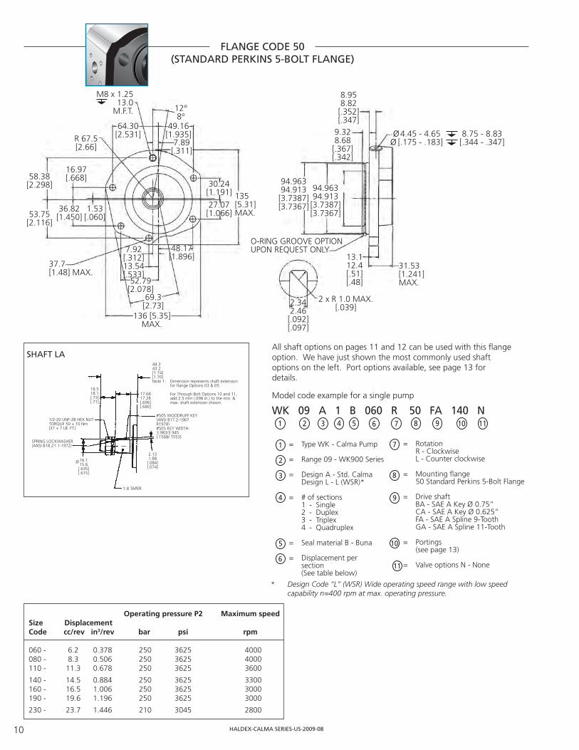
FLANGE CODE 50(STANDARD PERKINS 5-BOLT FLANGE)
37.7[1.48] MAX.
R 67.5[2.66]
58.38[2.298]
53.75[2.116]
16.97[.668]
36.82[1.450]
1.53[.060]
64.30[2.531]
M8 x 1.2513.0
M.F.T. 12°8°
49.16[1.935]
7.89[.311]
30.24[1.191]
27.07[1.066]
135[5.31]MAX.
48.17[1.896]
7.92[.312]13.54[.533]
52.79[2.078]
69.3[2.73]
136 [5.35]MAX.
94.96394.913
[3.7387][3.7367]
94.96394.913[3.7387][3.7367]
13.112.4[.51][.48]
31.53[1.241]MAX.
9.328.68[.367][.342]
8.958.82
[.352][.347]
4.45 - 4.65[.175 - .183]
8.75 - 8.83[.344 - .347]
O-RING GROOVE OPTIONUPON REQUEST ONLY
2.342.46
[.092][.097]
2 x R 1.0 MAX.[.039]
ØØ
= Type WK - Calma Pump
= Range 09 - WK900 Series = Design A - Std. Calma Design L - L (WSR)* = # of sections 1 - Single 2 - Duplex 3 - Triplex 4 - Quadruplex
= Seal material B - Buna
= Displacement per section (See table below)
Model code example for a single pump
= Rotation R - Clockwise L - Counter clockwise
= Mounting fl ange 50 Standard Perkins 5-Bolt Flange
= Drive shaft BA - SAE A Key Ø 0.75” CA - SAE A Key Ø 0.625” FA - SAE A Spline 9-Tooth GA - SAE A Spline 11-Tooth = Portings (see page 13) = Valve options N - None
1 2 3 4 5 6 7 8 9 10 11
WK 09 A 1 B 060 R 50 FA 140 N
Operating pressure P2 Maximum speedSize Displacement Code cc/rev in3/rev bar psi rpm
060 - 6.2 0.378 250 3625 4000080 - 8.3 0.506 250 3625 4000110 - 11.3 0.678 250 3625 3600
140 - 14.5 0.884 250 3625 3300160 - 16.5 1.006 250 3625 3000190 - 19.6 1.196 250 3625 3000
230 - 23.7 1.446 210 3045 2800
All shaft options on pages 11 and 12 can be used with this fl angeoption. We have just shown the most commonly used shaft options on the left. Port options available, see page 13 for details.
SHAFT LA
1
2
3
4
5
6
7
8
9
10
11
44.343.2[1.74][1.70]Note 1: Dimension represents shaft extension for flange Options 03 & 05.
For Through Bolt Options 10 and 11, add 2.5 mm (.098 in.) to the min. & max. shaft extension shown.
18.518.1[.73][.71]
17.6817.28[.696][.680]
1/2-20 UNF-2B HEX NUTTORQUE 50 + 10 Nm[37 + 7 LB. FT.]
SPRING LOCKWASHER(ANSI B18.21.1-1972)
16.115.6[.635][.615]
Ø
1:8 TAPER
2.131.88
[.084][.074]
#505 WOODRUFF KEY(ANSI B17.2-1967R1978)#505 KEY WIDTH:3.983/3.945[.1568/.1553]
* Design Code “L” (WSR) Wide operating speed range with low speed capability n=400 rpm at max. operating pressure.

HALDEX-CALMA SERIES-US-2009-08 11
SHAFT OPTIONS
STRAIGHT SHAFT SAE ”A” Ø .75” ORDER CODE BA STRAIGHT SHAFT SAE Ø .625” ORDER CODE CA
SAE ”A” SPLINE 9-TOOTH ORDER CODE FA SAE ”A” SPLINE 11-TOOTH ORDER CODE GA
DIN 5480 SPLINE 14 TOOTH ORDER CODE HA DIN 5482 SPLINE 9 TOOTH ORDER CODE JA
A critical element which must be considered when specifying a Calma pump for your application is the shaft drive system. Haldex has both the product and the application experience to insure that your Calma pump incorporates the correct shaft for your application. The follow-ing depict the 11 standard shaft options for the Calma family. Our fl exible manufacturing capabilities can accommodate a wide variety of shaft confi gurations.
4.75 x 4.75 x 22.2[.187 x .187 x .875]KEY
32.531.5[1.27][1.24]Note 1:Dimension represents shaft extension for flange Options 03 & 05.
For Through Bolt Options 10 and 11, add 2.5 mm (.098 in.) to the min. &max. shaft extension shown.
26.325.9[1.03][1.01]
21.2320.97[.836][.826]
19.0519.02[.750][.749]
Ø
24.123.7[.94][.93]
19.0519.02[.750][.749]
Ø
18.317.9[.72][.71]
32.531.5[1.27][1.24]Note 1:(SEE ORDER CODE BA)
EXTERNAL INVOLUTE SPLINE16/32 DP, 9 TEETH,FLAT ROOT, SIDE FIT
17.7317.47[.698][.688]
15.8815.85[.625][.624]
Ø
32.531.5[1.27][1.24]Note 1:(SEE ORDERCODE BA)
24.223.8[.95][.93]
3.97 x 3.97 x 19.05[.156 x .156 x .75]KEY
19.5019.39 (19.5 hll)[.768][.763]
Ø
24.523.5[.96][.92]Note 1:(SEE ORDERCODE BA)13.9
13.7[.54][.53]
EXTERNAL INVOLUTE SPLINEW20 x 1.25 x 9g, 14 TEETH,FLAT ROOT, SIDE FIT
16.5016.39 (16.5 hll)[.650][.645]
Ø
23.522.5[.92][.88]Note 1:(SEE ORDERCODE BA)
18.217.8[.71][.70]
EXTERNAL INVOLUTE SPLINEB17 x 14, DIN 5482, 9 TEETH,FLAT ROOT, SIDE FIT
14.213.9[.55][.54]

HALDEX-CALMA SERIES-US-2009-0812
KEY, WASHER AND NUT INCLUDED WITH PUMP, WHERE APPLICABLE.
SHAFT OPTIONS(Cont.)
TANG SHAFT ORDER CODE QBSTRAIGHT SHAFT SAE ”A” Ø .75” ORDER CODE LA
SAE ”A” SPLINE 9-TOOTH ORDER CODE MB
DIN 5480 SPLINE 14 TOOTH ORDER CODE NB
19.118.9[.75][.74]
Ø
6.76.5[.26][.25]
WET TANG DRIVE (SEE MOUNTING FLANGEOPTIONS 12 & 13 FOR SHAFT DIMENSIONS
7.9757.917[.314][.312]
3.22.7[.12][.11]
8.158.05[.321][.317]
Ø 34.133.9[1.343][1.335]
STANDARD COUPLING INCLUDEDWITH SHAFT OPTION QB
22.322.0[.878][.866]
12.1211.90[.476][.469]
Ø
FLEX COUPLING
1/4”-20 UNC SCREW
9.6 6.45.4
40.438.9Ø
OLDHAM COUPLING (FLEX)
44.343.2[1.74][1.70]Note 1: Dimension represents shaft extension for flange Options 03 & 05.
For Through Bolt Options 10 and 11, add 2.5 mm (.098 in.) to the min. & max. shaft extension shown.
18.518.1[.73][.71]
17.6817.28[.696][.680]
1/2-20 UNF-2B HEX NUTTORQUE 50 + 10 Nm[37 + 7 LB. FT.]
SPRING LOCKWASHER(ANSI B18.21.1-1972)
16.115.6[.635][.615]
Ø
1:8 TAPER
2.131.88
[.084][.074]
#505 WOODRUFF KEY(ANSI B17.2-1967R1978)#505 KEY WIDTH:3.983/3.945[.1568/.1553]
38.437.4[1.51][1.47]Note 1:(SEE ORDER CODE LA)
13.613.2[.54][.52]
17.617.2
[.691][.675]
M12 X 1.5 HEX NUT (DIN 936)TORQUE 50 + 10 Nm [37 + 7 LB. FT.]
SPRINGLOCKWASHER(DIN 7)
17.117.0[.673][.669]
Ø
1:5 TAPER
1.8[.07]
3 X 5 KEY(DIN 6888)KEY WIDTH:3.000/2.975[.1181/.1171]
40.139.3[1.58][1.55]Note 1:(SEE ORDER CODE LA)27.6
27.2[1.09][1.07]
12.03511.965[.474][.471]
M12 X 1.5 HEX NUT(DIN 936) TORQUE 50 + 10 Nm[37 + 7 LB. FT.]
SPRINGLOCKWASHERB 12 (DIN 127)
16.65[.656]
Ø
1:8 TAPER
1.711.46
[.067][.058]
#405 WOODRUFF KEY(ANSI B17.2-1967R1978)
#405 KEY WIDTH:3.188/3.150[.1255/.1240]
SINGLE SECTION SHAFT LOADINGMax. drive shaft load index “A”, see table below.
A = (p1 x V1)
Note: P = actual pressure in psi, V = appli-cable displacement from Table pages 6-10.
DriveShaft
Load Index“A”
DriveShaft
Load Index“A”
BA 9257 HA 10010
CA 5005 JA 5505
FA 4640 QB 4353
GA 8505

HALDEX-CALMA SERIES-US-2009-08 13
PORT OPTIONS
93.7[3.69]MAX.
INLET OUTLET
YZ
REAR PORTS SHOWN IN VIEWSIDE PORTS ARE STANDARD
USE OF REAR PORT COVER WILLINCREASE MAX. VALUES OFOVERALL LENGTH DIMENSIONSBY 10.0 (.39).
FOR THRU BOLT VERSIONS, USE DIMENSIONS M (SEE PG 5) OR W (SEE PG 10) FOR CALCULATING SCREW LENGTH THE PUMP LENGTH WILL REQUIRE.
PUM
P M
OU
NTI
NG
FA
CE
F TH’D ØA
B
C
AB
C
45°
90°
SEE PAGES 6 - 10 FOR DIMENSIONS FROM FLANGEMOUNTING FACE TO PORTCENTERLINE.
COUNTERBORE DIA.SEE TABLE
SAE STRAIGHT THREAD PORTPER S.A.E. j514b
INLET[IN]
OUTLET[IN]
DISP.ORDERCODE
SIDEPORTCODE
REAR PORT CODE
PORT SIZEINLET
OUTLET
COUNTERBOREDIA.
MIN. [IN]
Y± 0.3
[± .012]
Z± 0.3
[± .012]
060 101 5017/8-143/4-16
34.14 [1.344]30.18 [1.188]
20.2[.795]
20.2[.795]
080-160 102 5021-1/16-12
7/8-1441.28 [1.625]34.14 [1.344]
20.2[.795]
20.2[.795]
190-230 103 5031-5/16-121-1/16-12
48.51 [1.910]41.28 [1.625]
24.2[.950]
22.2[.870]
BSPP STRAIGHT THREAD PORTPER DIN 3852, PART 2
060-190 121 521G 3/4G 1/2
33.0 [1.29]28.0 [1.10]
20.2[.795]
20.2[.795]
230 122 522G 1
G 3/441.0 [1.61]33.0 [1.29]
24.2[.950]
22.2[.870]
PERFORMANCE ON PAGE 3 REPRESENTS THAT WHICH CAN BE EXPECTED FROM UNITS INCORPORATING FLANGE PORTS.
The standard size for each type of port is outlined below.
S.A.E. SPLIT FLANGE PER S.A.E. j518c (STANDARD PRESSURE SERIES)
DISP.ORDERCODE
SIDEPORTCODE
PORT SIZEINLET
OUTLET
Ø A
[IN]
B
[IN]
C
[IN]
F TH’D xMIN. FULL TH’D
DEPTH
060-190 1403/41/2
19.05 [.750]12.7 [.500]
22.22 [.875]17.47 [.688]
47.63 [1.875]38.1 [1.50]
3/8-16 X 22 [.88] 5/16-18 X 24 [.94]
230 1411
3/425.4 [1.00]25.4 [1.00]
26.19 [1.031] 22.22 [.875]
52.37 [2.062]47.63 [1.875]
7/16-14 X 22 [.88] 3/8-16 X 22 [.88]
METRIC SPLIT FLANGE PER ISO/DIS 6162 (35 to 350 BAR SERIES)
DISP.ORDERCODE
SIDEPORTCODE
PORT SIZEINLET
OUTLET
Ø A
[IN]
B
[IN]
C
[IN]
F TH’D xMIN. FULL TH’D
DEPTH
060-190 1451913
19.05 [.750]12.7 [.500]
22.22 [.875]17.47 [.688]
47.63 [1.875]38.1 [1.50]
M10 X 25 [.984] M8 X 21 [.823]
230 1462519
25.4 [1.00]19.05 [.750]
26.19 [1.031] 22.22 [.875]
52.37 [2.062]47.63 [1.875]
M10 X 23 [.906] M10 X 25 [.984]
SEE PAGES 6 - 10 FOR DIMENSIONS FROM FLANGEMOUNTING FACE TO PORTCENTERLINE.
SEE PAGES 6 - 10 FOR DIMENSIONS FROM FLANGEMOUNTING FACE TO PORTCENTERLINE.
EUROPEAN 4-BOLT FLANGEDISP.ORDERCODE
SIDEPORTCODE
PORT SIZEINLET
OUTLET
Ø A
[IN]
B
[IN]
F TH’D xMIN. FULL TH’D
DEPTH
060-190 1502015
40.0 [1.575]35.0 [1.378]
20 [.78]15 [.59]
M6 X 13 [.51]M6 X 13 [.51]
230 1512618
55.0 [2.165]55.0 [2.165]
26 [1.02] 18 [.71]
M8 X 13 [.51]M8 X 13 [.51]

HALDEX-CALMA SERIES-US-2009-0814
CALMA MULTIPLE PUMPS
The two following parameters are of the utmost impor-tance when selecting multiple pumps and must never be exceeded:- Drive shaft load index “A” in chart at right.- Internal coupling load index “K” in Coupling Loading below at right.
In multiple pumps, shaft end section must have larg-est displacement. Each consecutive section must have displacement equal to or smaller than section preceding.
REDUCED INLET MULTIPLE PUMPSReduced inlets provide overall system savings by reducing the cost of redundant inlet hose and fi ttings. Contact Haldex regarding your reduced inlet multiple pump application.
Haldex multiple pumps are also available with reduced number of inlets. Please contact Haldex for details. Please contact Haldex for pump applications requiring independently sealed sections.
MULTIPLE SECTION SHAFT LOADINGMax. drive shaft load index “A”, see table below. for double pump A = (p1 x V1) + (p2 x V2)
for triple pump A = (p1 x V1) + (p2 x V2) + (p3 x V3)
for quadruple pump A = (p1 x V1) + (p2 x V2) + (p3 x V3) + (p4 xV4)
Note: P = actual pressure in psi, V = appli-cable displacement from Table pages 6-10.
DriveShaft
Load Index“A”
DriveShaft
Load Index“A”
BA 9257 HA 10010
CA 5005 JA 5505
FA 4640 QB 4353
GA 8505
COUPLING LOADINGMax. load index “K” 4640: for double pump K = (p2 x V2)
for triple pump K = (p2 x V2) + (p3 x V3)
for quadruple pump K = (p2 x V2) + (p3 x V3) + (p4 xV4)
Note: P = actual pressure in psi, V = appli-cable displacement from Table pages 6-10.
P R MAX.
Q S
CLOCKWISEROTATION
INLET OUTLET
CLOCKWISEROTATION
INLET OUTLET
P T R MAX.
Q S S
N
R MAX.
LS S
T W
Dimensions N & L are for use with Flange Options 10 thru 13.
DOUBLE SECTION / DUAL INLET
TRIPLE SECTION / TRIPLE INLET
Size P Q Weight R S Weight T Weight N L Weight in in lbs in in lbs in lbs in in lbs Shaft end section Rear section 2nd & 3rd section A1-section
060 - 0.378 in3 3.05 1.73 6.8 2.88 1.00 5.9 2.32 3.9 2.95 1.63 5.9080 - 0.506 in3 3.14 1.79 7.0 3.00 1.06 6.1 2.44 4.1 3.07 1.63 5.9110 - 0.689 in3 3.34 1.87 7.4 3.18 1.14 6.6 2.61 4.6 3.24 1.77 6.6
140 - 0.884 in3 3.52 1.96 7.7 3.35 1.24 6.8 2.79 4.8 3.42 1.87 6.8160 - 1.006 in3 3.63 2.02 7.9 3.46 1.29 7.0 2.90 5.0 3.53 1.92 7.0190 - 1.196 in3 3.81 2.11 8.1 3.64 1.38 7.4 3.08 5.2 3.71 2.01 7.4
230 - 1.446 in3 4.04 2.22 8.5 3.88 1.50 7.7 3.31 5.7 3.94 2.12 7.7
NOTE: Dimensions above are for Design Code “A”.

Only Haldex offers this extensive range of hydraulic pumps, hydraulic motors, electro-hydraulic power units and rotary fl ow dividers worldwide.
GC Series Hydraulic PumpsCompact cast iron gear pumps with a wide variety ofintegrated options provide custom systems capability andhigh-effi fi ency performance. Displacements from 0.065 to0.711 cu. in. (1.066 to 11.65 cc) per revolution. Pressures to4,000 psi (276 Bar).
W Series Gear PumpsHighly effi cient pumps feature 4,000 psi continuousoperation, speed range from 500 to 4,000 rpm, low noiseoperation and overall effi ciency greater than 90%.Displacements from .183 to 3.05 cu. in. (3 to 50 cc) perrevolution. Other features include SAE, ISO and DIN shafts,fl anges and ports; integrated valves and multiple pumpconfi gurations.
F20LS/F30LS Load Sense Variable Discharge Gear PumpsOffers the horsepower conservation of a load sense systemand the low cost reliability of a gear pump. Featuring cast ironconstruction and 4,000 psi continuous operation for severe-duty applications. Displacements from 1.41 to 9.82 cu. in. (23 to 161 cc).
F20 & F30 Series Gear PumpsRugged cast iron pumps offer high performance for severe-duty applications. Available in single, multiple and through-drive versions. Displacements from 1.41 to 9.82 cu. in. (23 to161 cc) per revolution. Pressures to 4,000 psi (276 Bar) continuous.
F20 / G30 Specialty Products• F20-DM Pump/Motor Series, F20 series pump with directmount motor options. Motor options --- 7.5 HP, 10 HP, and 15HP and displacements from 1.41 to 2.94 cu. in. (23 to 48 cc)for pump/motor units. Integral manifold options also available.• F20 / F30 PTO Pump Series. Specifi cally designed pumpoptions and features for PTO (power take off) applications.Displacements from 1.41 to 9.82 cu. in. (23 to 161 cc).• F20 / F30 two section fl ow dividers. Displacements from1.41 to 9.82 cu. in. (23 to 161 cc) per section. Pressures to 4,000 psi continuous (276 Bar).
Gerotor PumpsHigh-effi ciency, low-maintenance design with quiet operationand uniform fl ow. Extremely tolerant of contamination.Displacements from 0.05 to 8.29 cu. in. (0.8 to 135.8 cc) perrevolution. Pressures to 2,000 psi (136 Bar).
GC-9500 AC Hydraulic Power UnitsAC power units offering the ultimate in design versatility and ordering fl exibility. It can be ordered completely assembled or in kits. Standard options include: 81 motors (1/2-5 hp, TEFC, open, drip-proof, explosion proof motors); 4 reservoirs (5,10, 15 and 20 gal.); and 18 pumps (pressure balanced and high/low with fl ows to 28 gpm and pressures to 3500 psi).
HE AC & DC Hydraulic Power PacksSelf-contained modular power systems in fully assembled orcomponent form; wide range of standard pumps, motors,switches, mounts, valves, and reservoirs. Custom optionsalso available. Pressures to 4,000 psi (276 Bar). Flows from 0.20 to 7.0 GPM.
Hydraulic MotorsAvailable in the GC, W and F20 Series in unidirectional andbirotational confi gurations. Motors available with modularvalve, bearing, seal and shaft options for maximum fl exibility.Displacements from 0.065 to 5.30 cu. in. (1.06 to 87.0 cc) perrevolution. Pressures to 4,000 psi (276 Bar).
Two-Stage Hydraulic PumpsExternal gear pumps designed for high-speed positioningcombined with maximum working pressure. High-pressuredisplacements from 0.258 to 1.395 cu. in. (4.23 to 22.86 cc)per revolution. Pressures to 4,000 psi (276 Bar). Flows from 5 to 28 GPM.
Rotary Flow DividersRotary-gear units up to four sections for synchronizedoperation of multiple cylinders or motors, proportionaldivision of output or intensifi ed fl ow. Single-sectiondisplacements from 0.065 to 0.813 cu. in. (1.0 to 13.32 cc)per revolution. Pressures to 4,500 psi (306 Bar).
Call us for more informationFor application assistance or detailed literature on anyHaldex product line, call us toll-free: 1-800-572-7867.Visit our web site: http://www.haldex.com/hbusE-mail us: [email protected]

Haldex (www.haldex.com), headquartered in Stockholm, Sweden, is a provider of
proprietary and innovative solutions to the global vehicle industry, with focus on products in vehicles that enhance safety, environment and vehicle dynamics.Haldex is listed on the Stockholm Stock Exchange and had net sales of nearly 8.5 billion SEK in 2008. The number of employees amounts to about 5,000.
PRODUCT RANGE
HE Powerpacks12/24/48 VDC 0.3 – 4.5 kW and 0.75 – 3 kW AC modular power packs
HE Box Powerpacks12/24/48 VDC modular powerpacks in weatherproof boxes
Pressure Switches5 - 350 bar, connecting/disconnecting
W100 Hydraulic pumps0.5 - 2.0 cc 227 bar
W300 Hydraulic pumps0.8 – 5.7 cc 230 bar
W600 Hydraulic pumps3 – 12 cc 276 bar
WM600 Hydraulic motors3 – 12 cc 276 bar
W900 Hydraulic pumps5 – 31 cc/section 276 bar
WM900 Hydraulic motors5 - 31 cc/section 276 bar
WQ900 The quiet pumps5 - 23 cc/section 230 bar
FERRA Heavy duty pumps16 - 41 cc/section 276 bar
WP900X Hydraulic pumps16 - 31 cc/section 276 bar
W1500 Hydraulic pumps19 - 50 cc/section 276 bar
WM1500 Hydraulic motors19 - 50 cc/section 276 bar
GPA Internal Gear pumps1.7 – 63 cc/section 100 bar
GC Hydraulic pumps1.06 – 11.65 cc/section 276 bar
II-Stage Hydraulic pumps 4.2 – 22.8 cc/section 276 bar
Rotary Flow Dividers3.8 – 13.3 cc/section 300 bar
F20/F30 (LS) Hydraulic pumps23 – 161 cc/section 276 bar
Transmission pumps
www.haldex.com/hbus
Haldex Hydraulics AB Nymärsta Gränd 6Box 511 SE-195 25 MÄRSTASweden Tel: +46–8 591 288 50 Fax: +46-8 591 288 60 [email protected]
Haldex Hydraulics AB Ringvägen 3SE-280 40 SK. FAGERHULT Sweden Tel: +46-433 324 00 Fax: +46-433 305 [email protected]
Haldex Hydraulics GmbH Seligenweg 12Postfach 1507 DE-95014 HOFGermany Tel: +49-9281 895-0 Fax: +49-9281 [email protected]
Haldex Hydraulics Corp. 2222 15th StreetROCKFORD, IL 61104USA Tel: +1-815 398 44 00 Fax: +1-815 398 59 [email protected]
Haldex Hydraulics Corp. 214 James Farm Road Statesville, NC 28625USA Tel: +1-704 873 25 87 Fax: +1-704 838 79 [email protected]
Haldex International Trading (Shanghai) Co. Ltd.16 A, Zhao Feng World Trade BuildingNo. 369 Jiang Su Road, CN-200050 SHANGHAIChinaTel +86 21 5240 0338Fax +86 21 5240 [email protected]
HA
LDEX
-CA
LMA
SER
IES-
US-
2009
-08