Callaway, Unit 1 - Revision of TS 2.1.1.1 and 5.6.5 To ... · Section 4.4.2.2.1. Table 1 and Table...
51
2:’Aiiieren Center MISSOURI May 08, 2015 ULNRC-062 15 U.S. Nuclear Regulatory Commission Attn: Document Control Desk Washington, DC 20555-0001 10 CFR 50.90 Ladies and Gentlemen: DOCKET NUMBER 50-483 CALLAWAY PLANT UNIT 1 UNION ELECTRIC CO. FACILITY OPERATING LICENSE NPF..30 REVISION OF TS 2.1.1.1 AND 5.6.5 TO REMOVE UNCERTAINTIES FROM THE DNBR SAFETY LIMIT AND ADOPT APPROVED WCAP44565-P-A METHODOLOGY Pursuant to 1 0 CFR 50.90, “Application for amendment oflicense or construction permit,” Ameren Missouri (Union Electric Company) herewith transmits an application for amendment to Facility Operating License Number NPF-30 for the Callaway Plant. The proposed amendment would modify Technical Specification (TS) requirements to adopt the NRC approved methodology described in WCAP-14565P-A Addendum 2-P-A. This Topical Report describes the qualifications ofthe extended application ofthe ABB-NV and Westinghouse Low Pressure (WLOP) correlations as an alternative to the currently used W-3 correlation, in supplement to the primary Departure from Nucleate Boiling (DNB) correlation for Westinghouse Pressurized Water Reactor (PWR) fuel designs with the Westinghouse version ofthe VIPRE-Ol (VIPRE) code. Specifically, TS 5.6.5 would be revised to include WCAP-14565-P-A Addendum 2-P-A as an NRC approved analytical method for determining core operating limits for Callaway. In addition, as part of the proposed amendment, TS 2. 1 . 1 . 1 would also be revised to provide a safety limit for the Departure from Nucleate Boiling Ratio (DNBR) that is aligned with the original intent of approved topical report WCAP-14483 and would reduce the need for potential cycle-specific license amendments resulting from a change in calculated uncertainties determined using methodologies previously approved for use at Callaway. The appropriate TS Bases changes for the proposed revisions are included for information and reflect the proposed changes. PQ Box 620 Futton MO 65251 AmerenMissoun corn STARS AiHance
Transcript of Callaway, Unit 1 - Revision of TS 2.1.1.1 and 5.6.5 To ... · Section 4.4.2.2.1. Table 1 and Table...

2:’Aiiieren CenterMISSOURI
May 08, 2015
ULNRC-062 15
U.S. Nuclear Regulatory CommissionAttn: Document Control DeskWashington, DC 20555-0001
10 CFR 50.90
Ladies and Gentlemen:
DOCKET NUMBER 50-483CALLAWAY PLANT UNIT 1UNION ELECTRIC CO.
FACILITY OPERATING LICENSE NPF..30REVISION OF TS 2.1.1.1 AND 5.6.5 TO REMOVE UNCERTAINTIES FROM THE DNBRSAFETY LIMIT AND ADOPT APPROVED WCAP44565-P-A METHODOLOGY
Pursuant to 1 0 CFR 50.90, “Application for amendment oflicense or construction permit,” AmerenMissouri (Union Electric Company) herewith transmits an application for amendment to FacilityOperating License Number NPF-30 for the Callaway Plant.
The proposed amendment would modify Technical Specification (TS) requirements to adopt the NRCapproved methodology described in WCAP-14565P-A Addendum 2-P-A. This Topical Reportdescribes the qualifications ofthe extended application ofthe ABB-NV and Westinghouse LowPressure (WLOP) correlations as an alternative to the currently used W-3 correlation, in supplement tothe primary Departure from Nucleate Boiling (DNB) correlation for Westinghouse Pressurized WaterReactor (PWR) fuel designs with the Westinghouse version ofthe VIPRE-Ol (VIPRE) code.
Specifically, TS 5.6.5 would be revised to include WCAP-14565-P-A Addendum 2-P-A as an NRCapproved analytical method for determining core operating limits for Callaway. In addition, as part ofthe proposed amendment, TS 2. 1 . 1 . 1 would also be revised to provide a safety limit for the Departurefrom Nucleate Boiling Ratio (DNBR) that is aligned with the original intent of approved topical reportWCAP-14483 and would reduce the need for potential cycle-specific license amendments resultingfrom a change in calculated uncertainties determined using methodologies previously approved for useat Callaway.
The appropriate TS Bases changes for the proposed revisions are included for information and reflectthe proposed changes.
PQ Box 620 Futton MO 65251 AmerenMissoun corn
STARS AiHance
ULNRC-062 15May 08, 2015Page 2
Attachments I through 4 provide the Technical Specification Page Markups, Proposed TechnicalSpecification Bases Page Markups, Retyped Technical Specifications Pages, and Proposed FSARChanges, respectively, in support ofthis amendment request. Attachments 2 and 4 are provided forinformation only. final TS Bases changes will be processed under the program for updates per IS5.5.14, “Technical Specifications Bases Control Program,” at the time this amendment isimplemented. Final FSAR changes will be processed under the process for FSAR updates pursuant to10 CFR 50.7 1(e).
It has been determined that this amendment application does not involve a significant hazardconsideration as determined per I 0 CFR 50.92, “Issuance of amendment.” In addition, pursuant to 10CFR 5 1 .22, “Criterion categorical exclusion or otherwise not requiring environmental review,” Section(b), no environmental impact statement or environmental assessment need be prepared in connectionwith the issuance ofthis amendment. It should also be noted that this submittal does not contain newcommitments.
The Callaway Onsite Review Committee has reviewed and approved the proposed changes and hasapproved the submittal ofthis amendment application.
This amendment request is being submitted in support of operations following the conclusion ofCallaway refuel outage 21, scheduled for spring 2016. Ameren Missouri requests approval of therequested license amendment prior to reactor criticality during the restart from the upcoming Refuel 21outage. Reactor criticality is currently scheduled for May 4, 2016. Ameren Missouri further requeststhat the license amendment be made effective upon NRC issuance, to be implemented within 90 daysfrom the date of issuance,
In accordance with 1 0 CFR 50.91 “Notice for public comment; State consultation,” Section (b)(1), acopy ofthis amendment application is being provided to the designated Missouri State official.Ifthere are any questions, please contact Mr. Tom Elwood at 314-225-1905.
I declare under penalty ofperjury that the foregoing is true and correct.
Sincerely,
Scott A. MaglioManager, Regulatory Affairs
Executed on: ‘ 2o I

ULNRC-062 I 5May 08, 2015Page 3
Enclosure: Description and Assessment ofthe Proposed Change
Attachments to the Enclosure:1 . Technical Specification Page Markups2. Proposed Technical Specification Bases Page Markups3. Retyped Technical Specification Pages4. Proposed fSAR Changes

ULNRC-06215May 08, 2015Page 4
cc: Mr. Marc L. DapasRegional AdministratorU. S. Nuclear Regulatory CommissionRegion IV1600 East Lamar BoulevardArlington, TX 76011-4511
Senior Resident InspectorCallaway Resident OfficeU. S. Nuclear Regulatory Commission8201 NRC RoadSteedman, MO 65077
Mr. Fred LyonProject Manager, Callaway PlantOffice ofNuclear Reactor RegulationU. S. Nuclear Regulatory CommissionMail Stop O-8B1Washington, DC 20555-2738
ULNRC-062 15May08, 2015Page 5
Index and send hardcopy to QA File A160.0761
Hardcopy:
Certrec Corporation41 50 International Plaza Suite 820Fort Worth, TX 76109(Certrec receives ALL attachments as long as they are non-safeguards and may be publicly disclosed.)
Electronic distribution for the following can be made via Tech Spec ULNRC Distribution:
F. M. Diyaa w. NetererL. H. GraessleT. E. HemtiannB. L CoxL. H. KanuckelS. A. MaglioT. B. ElwoodLB. LittleCorporate CommunicationsNSRB SecretarySTARS Regulatory AffairsMr. John O’Neill (Pillsbury Winthrop Shaw Pittman LLP)Missouri Public Service CommissionMs. Leanne Tippett-Mosby (DNR)

Enclosure to ULNRC-062 ISPage 1
DESCRIPTION AND ASSESSMENT OF THE PROPOSED CHANGE
1. SUMMARY DESCRIPTION Page 2
2. DETAILED DESCRIPTION Page 2
3. TECHNICAL EVALUATION Page 2
4. REGULATORY EVALUATION Page 4
4.1 Applicable Regulatory Requirements/Criteria Page 4
4.2 No Significant Hazards Consideration Determination Page 5
5. ENVIRONMENTAL EVALUATION Page 8
6. REFERENCES Page 8

Enclosure to ULNRC-.062 15Page 2
DESCRIPTION AND ASSESSMENT OF THE PROPOSED CHANGE
1.0 SUMMARY DESCRIPTION
This evaluation supports a request to amend Operating License NPF-30 for Callaway Plant. Theproposed changes would revise the Operating License to approve the application ofWCAP-14565P-AAddendum 2-P-A (Reference 1) and to simplify how the departure from nuclear boiling ratio (DNBR)safety limit is presented in the Technical Specifications (TS), in order to reduce the need forpotentially unnecessary, subsequent license amendments.
2.0 DETAILED DESCRIPTION
OLR Analytical Method
TS 5.ói.b identifies the approved Topical Reports and analytical methods used to determine the coreoperating limits. This section will be revised to add the following reference:
13. WCAP-14565-P-A Addendum 2-P-A, “Extended Application ofABB-NV Correlationand Modified ABB-NV Correlation WLOP for PWR Low Pressure Applications.”
Corresponding Bases and FSAR markups for the T$ 5.6.5.b change are provided in Attachment 2 and4, respectively, for information only. Any necessary Core Operating Limits Report (COLR) revisionswill be processed under the 10 CFR 50.59 process during Cycle 22 core re-design, when the TopicalReport is first expected to be used for analysis at Callaway.
Rector Core Safety Limits
TS 2.1.1 .1 will be revised to read:
2. 1 . 1 . 1 The departure from nucleate boiling ratio (DNBR) shall be maintained 1 .1?for the WRB2 DNB correlation.
Corresponding Bases revisions for the TS 2. 1 . 1 .1 change are provided in Attachment 2 for informationonly.
3.0 TECHNICAL EVALUATION
COLR Analytical Method
The proposed change modifies TS requirements to adopt the methodology described in WCAP-14565-PA, “Extended Application ofABB-NV Correlation and Modified ABS-NV Correlation WLOP forPWR Low Pressure Applications,” Addendum 2, also known as W-3A. Specifically, TS 5.6.5 wouldbe revised to include WCAP-.l4565P-A Addendum 2-P-A as an NRC approved analytical method fordetermining core operating limits for Callaway. The Topical Report justifies the use ofthe ABBNVcorrelation for the nonmixing grid region ofWestinghouse Pressurized Water Reactors (PWRs) with

Enclosure to ULNRC-062 15Page 3
no change to the correlation form, its coefficients, or the currently licensed DNBR limit. The TopicalReport also develops and validates the Westinghouse Low Pressure (WLOP) correlation and theproposed 95/95 DNBR limit for low pressure and low flow conditions.
Ameren Missouri has reviewed the NRC staffs final safety evaluation (SE) dated February 14, 2008[Accession No. ML0803 603 8 1] for WCAP-14565-PA, Addendum 2-P-A (Revision 0). Section 4.0 ofthe NRC staffs evaluation included four limitations and conditions for application ofthe TopicalReport. Ameren Missouri’s response to each ofthe limitations and conditions is as follows:
1 The applicable range ofthe ABB-NV and WLOP correlations are presented in Table 1 andTable 2, respectively, ofthis SE.
Response: For the departure from nucleate boiling (DNB) analyses conditions that were basedon the ABE-NV and WLOP correlations, the results were confirmed to be within the parameterranges ofthe DNB correlations as specified in Table I and Table 2, respectively.
Discussion ofthe applicable ranges for DNB correlations at Callaway is included in F$ARSection 4.4.2.2.1. Table 1 and Table 2 ofthe WCAP-14565-P-A Addendum 2P-A have beenincorporated into the proposed FSAR 4.4.2.2. 1 revisions included as Attachment 4 to thisEnclosure.
2. The ABB-NV correlation and the WLOP correlation must use the same f factor for powershape correction as used in the primary DNB correlation for a specific fuel design.
Response: for the DNB analyses conditions that were based on the ABB-NV and WLOPcorrelations, the F factor for power shape correction that was applied was the same as thepower shape correction used for the WRB-2 correlation, which is the primary DNB correlationfor the fuel at Callaway.
3 . Selection ofthe appropriate DNB correlation, DNBR limit, engineering hot channel factors forenthalpy rise, and other fuel-dependent parameters will be justified for each application of eachcorrelation on a plant specific basis.
Response: The ABE-NV and WLOP DNB correlations are used for the analysis of the fuelwhen the primary DNB correlation is not applicable. The current ABB-NV and WLOP DNBRlimits were approved for use with VJPRE. The 95/95 ABB-NV DNB correlation limit is 1.13for Westinghouse PWR fuel design applications. The 95/95 WLOP DNB correlation limit is1 .1 8. The correlation limits used in the VIPRE DNBR calculations for Callaway are consistentwith the approved values.
There is no fuel design change associated with the Callaway implementation ofABB-NV andWLOP. The plant specific hot channel factors and other fuel dependent parameters in theDNBR calculations are unchanged from the currently approved values.
4. The ABBNV correlation for Westinghouse PWR applications and the WLOP correlation mustbe used in conjunction with the Westinghouse version of the VIPRE-0 1 (VIPRE) code since

Enclosure to ULNRC-06215Page 4
the correlations were justified and developed based on VIPRE and the associated VIPREmodeling specifications.
Response: The Westinghouse version of the VIPRE-Ol subchannel analysis code, which hasbeen qualified and approved with the ABB-NV and WLOP correlations, was used for CallawayDNB analyses involving the ABBNV and WLOP correlations. This is reflected in the FSARmark ups provided for information only in Attachment 4 to this Enclosure.
Reactor Core Safeiy Limits
The proposed T$ 2. 1 . 1 . 1 change provides a safety limit for Departure from Nucleate Boiling Ratio(DNBR) of 2 I . I 7 for the WRB-2 DNB correlation. The current Callaway TS specifies the designlimit DNBR as the following:
2. 1 . I . 1 The design limit departure from nucleate boiling ratio (DNBR) shall bemaintained 1 .22 for transients analyzed using the revised thermal designprocedure (RTDP) methodology and the WRB-2 DNB correlation. For non-RTDP transients analyzed using the standard thermal design procedure, theDNBR shall be maintained greater than or equal to the applicable DNBcorrelation limit ( 1 . 1 7 for WRB-2, 1 .30 for W-3).
With this change, safety limit uncertainties applied to the primary WRB-2 correlation will now beapplied in the applicable approved safety analysis methodology instead ofbeing fixed in the TS.Removing the design uncertainties from the TS will provide a true safety limit consistent withapproved WCAP-14483-A, “Generic Methodology for Expanded Core Operating Limits Report,” andreduce the need for license amendments resulting from a change in calculated uncertainties determinedusing methodologies previously approved for use at Callaway.
This change does not alter the use of the analytical methods used to determine core operating limitsthat have been reviewed and approved by the NRC. Removing analytical uncertainties from the TSwould allow the use of current topical reports to refine those uncertainties without having to submit anamendment to the operating license, consistent with the intent ofWCAP-14483-A to reduce thepossibility ofinconect conclusions when determining ifa safety limit is met.
4.0 REGULATORY EVALUATION
4. 1 applicable Regplatory Requirements I Criteria
The regulatory requirements and/or guidance documents associated with this amendment applicationinclude the following:
. The regulatory basis for TS 5.6.5, “CORE OPERATING LIMITS REPORT (COLR),” is toensure core operating limits are established in accordance with NRC approved methodologiesand document those limits in the COLR.

Enclosure to ULNRC-06215Page 5
. Generic Letter 88-16, “Removal ofCycle-Specific Parameter Limits from TechnicalSpecifications,” provides guidance for the removal of cycle-specific parameter limits from theTS, since processing cycle-specific parameter limit changes was an unnecessary burden onboth licensees and the NRC. The Generic Letter was intended to apply to those TS changesthat were developed with NRC-approved methodologies. To support the removal of cycle-specific parameter limits, the Generic Letter recommends that cycle-specific parameter limitvalues be placed in a CORE OPERATING LIMITS REPORT (COLR), thereby eliminating theneed for many reload license amendments. The COLR would be submitted to the NRC toallow continued trending of information even though NRC approval of these limits would notbe required.
. 1 0 CFR 50,36(c)(5) requires that the TS include a category called “Administrative Control,”that contains the provisions relating to organization and management, procedures,recordkeeping, review and audit, and reporting necessary to assure operation of the facility in asafe manner.
There are no changes being proposed in this amendment application such that conformance orcommitments to the regulatory requirements and/or guidance documents above would come intoquestion. The evaluations documented herein confirm that Callaway Plant will continue to complywith all applicable regulatory requirements.
In conclusion, based on considerations discussed herein, (1) there is reasonable assurance that thehealth and safety of the public will not be endangered by operation in the proposed manner, (2) suchactivities will be conducted in compliance with the Commission’s regulations, and (3) issuance of theamendment will not be inimical to the common defense and security or to the health and safety of thepublic.
4.2 No Significant Hazards Consideration Determination
Ameren Missouri has evaluated whether or not a significant hazards consideration is involved with theproposed amendment by focusing on the three standards set forth in 10 CFR 50.92, “Issuance ofamendment,” as discussed below:
1 . Does the proposed change involve a significant increase in the probability or consequences of anaccident previously evaluated?
Response: No.
Overall protection system performance will remain within the bounds of the accident analysessince there are no design changes. The design ofthe reactor trip system (RTS) instrumentationwill be unaffected, and thus, the protection system will continue to function in a manner consistentwith the plant design basis. All applicable design, material, and construction standards willcontinue to be maintained.
Enclosure to ULNRC-062 15Page 6
The proposed changes will not affect any assumptions regarding accident initiators or precursorsnor adversely alter the design assumptions, conditions, and configuration ofthe facility or theintended manner in which the plant is operated and maintained. The proposed changes will notalter or prevent the ability ofstrucmres, systems, and components (S$Cs) from performing theirintended functions to mitigate the consequences of an initiating event within the assumedacceptance limits.
The proposed changes do not physically alter safety-related systems nor affect the way in whichsafety-related systems perfonn their functions. T$ 5.6.5.b continues to ensure that the analyticalmethods used to determine the core operating limits meet NRC reviewed and approvedmethodologies. TS 5.6.5.c, unchanged by this amendment application, will continue to ensure thatapplicable limits ofthe safety analyses are met.
The proposed change to TS 2. 1 . 1 . 1 to specify only the true DNBR safety limit without the additionof analytical uncertainties does not alter the use of the analytical methods used to determine coreoperating limits that have been reviewed and approved by the NRC. Removing analyticaluncertainties from the TS would allow the use of current topical reports to refine thoseuncertainties without having to submit an amendment to the operating license, consistent with theintent ofWCAP-14483-A. Implementation ofrevisions to topical reports for Callaway Plantapplications would still be reviewed in accordance with 10 CfR 50.59(c)(2)(viii) and, whererequired, receive prior NRC review and approval.
All accident analysis acceptance criteria will continue to be met with the proposed changes. Theproposed changes will not affect the source term, containment isolation, or radiological releaseassumptions used in evaluating the radiological consequences of an accident previously evaluated.The proposed changes will not alter any assumptions or change any mitigation actions in theradiological consequence evaluations in the FSAR. The applicable radiological dose acceptancecriteria will continue to be met.
Therefore, the proposed changes do not involve a significant increase in the probability orconsequences of an accident previously evaluated.
2. Does the proposed change create the possibility of a new or different kind of accident from anyaccident previously evaluated?
Response: No.
The ABB-NV correlation was originally developed for Combustion Engineering fuel designs, andhas also been qualified and licensed for Westinghouse fuel applications for the fuel region belowthe first mixing vane grid where the W-3 correlation is currently applied. The WLOP correlationis developed for DNBR calculations at low pressure conditions. The W-3A correlations, which arebased exclusively on DNB data from rod bundle tests, have a wider applicable range and are moreaccurate than the W-3 correlation, leading to increased DNB margin in the plant safety analyses.The NRC-approved ABB-NV and WLOP correlation 95/95 DNBR limits with the VIPRE-W codeare 1.13 and 1 .18, respectively.

Enclosure to ULNRC-062 15Page 7
The proposed change does not create the possibility of a new or different kind of accident from anyaccident previously evaluated, as the change is simply allowing the use ofmore accuratecorrelations when evaluating DNBR. The change does not involve any physical changes to thefacility.
Likewise, revising TS 2. 1 . 1 . 1 to present the DNBR safety limIt calculated using the WRB-2methodology, without uncertainties being applied, does not introduce any new or different failuremode from what has been previously been evaluated. The change does not involve any change to amethodology, including how uncertainties are calculated and accounted for, nor does it involve anyphysical change to the facility.
Collectively, and based on the above, the proposed changes do not create the possibility of a newor different kind of accident from any accident previously evaluated.
3 . Does the proposed change involve a significant reduction in a margin of safety?
Response: No.
The ABB-NV correlation was originally developed for Combustion Engineering fuel designs, andhas also been qualified and licensed for Westinghouse fuel applications for the fuel region belowthe first mixing vane grid where the W-3 correlation is currently applied. The WLOP correlationis developed for DNBR calculations at low pressure conditions. The W-3A correlations, which arebased exclusively on DNB data from rod bundle tests, have a wider applicable range and are moreaccurate than the W-3 correlation, leading to increased DNB margin in the plant safety analyses.Therefore, the proposed change does not involve a significant reduction in a margin of safety.
The currently listed Safety Limit in TS 2. 1 . I . 1 for DNBR of I .22 is calculated with someuncertainties statistically combined into the 1 . 1 7 value calculated using the WRB-2 methodology.These uncertainties are combined using the RTDP methodology described in WCAP-l 1397-P-A.Callaway FSAR Section 4.4. 1 . 1 discusses which uncertainties are statistically combined into thecorrelation limit.
Revising TS 2. 1 . 1 . 1 to present the DNBR safety limit calculated using the WRB-2 methodology,without uncertainties being applied, does not represent a change in methodology, but rather allowsfor changes in calculated uncertainties using methodologies previously approved for Callawaywithout requiring a license amendment. The proposed TS 2. 1 .1 . 1 revision does not represent achange in methodology for performing analyses.
The proposed changes do not eliminate any surveillances or alter the frequency of surveillancesrequired by the Technical Specifications. The nominal RTS and ESFAS trip setpoints (as well asthe associated allowable values) will remain unchanged. None ofthe acceptance criteria for anyaccident analysis will be changed.

Enclosure to ULNRC-0621 5Page 8
As there is no change to the source term, radiological release, or does mitigation functionsassumed in the accident analysis, the proposed changes have no impact on the radiologicalconsequences of a design basis accident.
Based on the above, the proposed changes do not involve a significant reduction in a margin ofsafety.
In consideration of all ofthe above, Ameren Missouri concludes that the proposed changes present nosignificant hazards consideration under the standards set forth in 10 CFR 50.92(c), and, accordingly, afinding of “no significant hazards consideration” is justified.
5.0 ENVIRONMENTAL EVALUATION
The proposed change would change a requirement with respect to installation or use of a facilitycomponent located within the restricted area, as defined in 1 0 CFR 20, or would change an inspectionor surveillance requirement. However, the proposed change does not involve (1) a significant hazardsconsideration, (ii) a significant change in the types or a significant increase in the amounts of anyeffluent that may be released offsite, or (iii) a significant increase in individual or cumulativeoccupational radiation exposure. Accordingly, the proposed change meets the eligibility criterion forcategorical exclusion set forth in I 0 CfR 51 .22(c)(9). Therefore, pursuant to 1 0 CFR 5 1 .22(b), noenvironmental impact statement or environmental assessment need be prepared in connection with theproposed change.
6.0 REFERENCES
1 A. Leidich, et. al., “Extended Application ofABB-NV Correlation and ModifiedABB-NV Correlation WLOP for PWR Low Pressure Applications,” WCAPI4565-PA Addendum 2-P-A (Proprietary), April 2008
2. D. S. Huegel, J. D. Andrachek, and C. E. Morgan, “Generic Methodology forExpanded Core Operating Limits Report,” WCAP-14483-A, January 1999.

Enclosure to ULNRC-06215Attachment IPage 1 of 3
ATTACHMENT 1
TECHNICAL SPECIFICATION PAGE MARKUPS

SLs2.0
2.0 SAFETYLIMITS(SLs)
2.1 SLs
2.1.1 Reactor Core S
In MODES I and 2, the combination ofTHERMAL POWER, Reactor CoolantSystem (RCS) highest loop average temperature, and pressurizer pressure shallnot exceed the limits specified in the COLR; and the following SLs shall not beexceeded:
2. 1 . I .1 The deeiR4Heparture from nucleate boiling ratio (DNBR) shallbe maintained 1-2 for taFciontc anaIyzCc[usingthe4ev:edth€41aLcin procedure the WRB-2DNB 0;i;T. ,
6taAøarQ nermaipmoedure1 theDNBRehalI beaiitaeqceaterthaww-nt’ri1th teppjDNBcarreItian1imit-(WrWRB4
2.1 . I .2 The peak fuel centerline temperature shall be maintained < 5080°F,decreasing by 58°F per 10,000 MWd/MTU of burnup.
2.1.2 RCSPressure SL
In MODES I1 2, 3 4, and 5, the RCS pressure shall be maintained 2735 psig.
2.2 SLViolations
2.2.1 If SL 2.1.1 is violated, restore compliance and be in MODE 3 within I hour.
2.2.2 IfSL 2.1.2 is violated:
2.2.2.1 In MODE I or 2, restore compliance and be in MODE 3 within Ihour.
2.2.2.2 In MODE 3, 4, or 5, restore compliance within 5 minutes.
CALLAWAY PLANT 2.0-I Amendment I 83

4 WCAP-12610-P-A, “VANTAGE + FUELASSEMBLY REFERENCECORE REPORT.
5. WCAP-1 I 397-P..A, “REVISED THERMAL DESIGNPROCEDURE.”
6. WCAR.f4565-P-A, “V1PRE-Ol MODELING AND QUALIFICATtONFOR PRESSURIZED WATER REACTOR NON-LOCA THERMAL.HYDRAULIC SAFETY ANALYSIS.”
7. WCAP-10851.-P-A, IMPROVED FUEL PERFORMANCEMODELS FOR WESTINGHOUSE FUEL ROD DESIGN ANDSAFETY EVALUATIONS.”
8. WCAP-1 5063-P-A, “WESTI NGHOUSE IMPROVEDPERFORMANCE ANALYSIS AND DESIGN MODEL (PAD 4.0).”
9. WCAP-8745-P-A, “DESIGN BASES FOR THE THERMALOVERPOWER DT AND THERMAL OVERTEMPERATURE DTTRIP FUNCTIONS.”
10. WCAP-10965-P-A, “ANC: A WESTINGHOUSE ADVANCEDNODAL COMPUTER CODE.”
If. WCAP-11596-P.A, “QUALIFiCATION OF THE PHOENIX-P/ANCNUCLEAR DESIGN SYSTEM FOR PRESSURIZED WATERREACTOR CORES.”
12. WCAP-13524-P-A, “APOLLO: A ONE DIMENSIONAL NEUTRONDIFFUSION THEORY PROGRAM.”
The core operating limits shall be determined such that all applicablelimits (e.g., fuel thermal mechanical limits, core thermal hydraulic limits,Emergency Core Cooling Systems (ECCS) limits, nuclear limits such as5DM, transient analysis limits, and accident analysis limits) of the safetyanalysis are met.
The COLR, including any midcycle revisions or supplements, shall beprovided upon issuance for each reload cycle to the NRC.
(continued)
t .
5.6 Reporting Requirements
Reporting Requirements5.6
[13. WCAP-14565-P-A Addendum 2-P-A, “Extended Application ofABB-NV Correlation andL Modified ABS-NV Correlation WLOP for PWR LowPressure ApplicaUons.”
CALLAWAY PLANT 5.0-24 Amendment I 90 I

Enclosure to ULNRC-062 I 5Attachment 2Page 1 of 5
ATTACHMENT 2
PROPOSED TECHNICAL SPECIFICATION BASES PAGE MARKUPS(for information only)
Reactor Core SLsB2.1.J
B 2.0 SAFETY LIMITS (SLs)
B 2.1.1 ReactorCore SLs
BASES
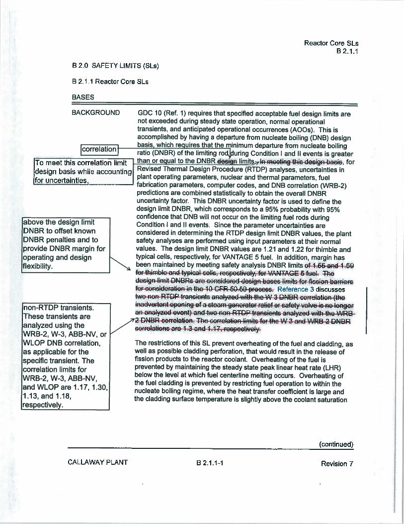
BACKGROUND GDC JO (Ref. 1) requires that specified acceptable fuel design limits arenot exceeded during steady state operation, normal operationaltransients, and anticipated operational occurrences (AOOs). This isaccomplished by having a departure from nucleate boiling (DNB) designbasis which re uires that the minimum departure from nucleate boiling
Condition I and II events is greaterthan oreqItotheDN limits rneetiwg thsdecibaci&, for
Idesign basis white accountingt Revised Thermal Design Procedure (RTDP) analyses, uncertainties in. . plant operating parameters nuclear and thermal parameters, fuelfor uncertainties, fabrication parameters, computer codes, and DNB correlation (WRB-2)
predictions are combined statistically to obtain the overall DNBRuncertainty factor. This DNBR uncertainty factor is used to define thedesign limit DNBR, which corresponds to a 95% probability with 95%confidence that DNB will not occur on the limiting fuel rods duringabove the design limit Condition I and II events. Since the parameter uncertainties are
DNBR to offset known considered in determining the RTDP design limit DNBR values, the plantDNBR penalties and to safety analyses are performed using input parameters at their normalprovide DNBR margin for values. The design limit DNBR values are I .21 and I .22 for thimble andoperating and design typical cells, respectively, for VANTAGE 5 fuel. In addition, margin hasflexibility.
%%%%%%, been maintained by meeting safety analysis DNBR limits e45d49ferthimblo an#picai eH&, cecpoctively,fer VANAGE64ueh The
.. design boe1ftofor4se1on brriercfor concier-ate4the Reference 3 discussestwo nonì RTDP4aientE 3aed with tbe W 3 DNBR oorrelation (thetnGdtapøn1ng of aeteam-gereratorrehef at safety va4ve-ic-+o4ongrana1zed event) and two nonRTDRtca,cient naiyzcdwith the
72 DNBR corretatiac The-correlation hmt#J fli 1JSJ LRDNBR,_z cofFe1atiGns3re1 .3an44çrecpectveiv.
The restrictions of this SL prevent overheating of the fuel and cladding, aswell as possible cladding perforation, that would result in the release offission products to the reactor coolant. Overheating ofthe fuel isprevented by maintaining the steady state peak linear heat rate (LHR)below the level at which fuel centerline melting occurs. Overheating ofthe fuel cladding is prevented by restricting fuel operation to within thenucleate boiling regime, where the heat transfer coefficient is large andthe cladding surface temperature is slightly above the coolant saturation
(continued)
non-RTDP transients.These transients areanalyzed using theWRB-2, W-3, ABE-NV, orWLQP DNB correlation,as applicable for thespecific transient. Thecorrelation limits forWRB-2, W-3, ABE-NV,and WLOP are 1.17, 1.30,1.13, and 1.18,respectively.
CALLAWAY PLANT B 2.1.1-1 Revision 7

JNO CHANGE TO J Reactor Core SLs[[SPAGE ] B2.1.1
BASES
BACKGROUND temperature. Fuel centerline melting occurs when the local LHR, or(CONTINUED) power peaking, in a region of the fuel is high enough to cause the fuel
centerline temperature to reach the melting point of the fuel. Expansionof the pellet upon centerline melting may cause the pellet to stress thecladding to the point of failure, allowing an uncontrolled release of activityto the reactor coolant. Reference 4 further discusses the fuel centerlinetemperature design basis.
Operation above the boundary of the nucleate boiling regime could resultin excessive cladding temperature because of the onset of DNB and theresultant sharp reduction in heat transfer coefficient. Inside the steamfilm, high cladding temperatures are reached, and a cladding water(zirconium water) reaction may take place. This chemical reaction resultsin oxidation of the fuel cladding to a structurally weaker form. Thisweaker form may lose its integrity, resulting in an uncontrolled release ofactivity to the reactor coolant.
The proper functioning of the Reactor Trip System (RTS) and steamgenerator safety valves prevents violation of the reactor core SLs.
APPLiCABLE The fuel cladding must not sustain damage as a result of normalSAFETY operation and AQOs. The reactor core SLs are established to precludeANALYSES violation of the following fuel design criteria:
a. There must be at least 95% probability at a 95% confidence level(the 95/95 DNB criterion) that the limiting hot fuel rod in the coredoes not experience DNB; and
b. The hot fuel pellet in the core must not experience centerline fuelmelting.
The Reactor Trip System Allowable Values in Table 3.3.1-1 , incombination with all the LCOs, are designed to prevent any anticipatedcombination of transient conditions for Reactor Coolant System (RCS)temperature, pressure, RCS flow, i’l, and THERMAL POWER level thatwould result in a departure from nucleate boiling ratio (DNBR) of less thanthe DNBR limit and preclude the existence of flow instabilities.
Protection for these reactor core SLs is provided by the proper operationof the steam generator safety valves and the following automatic reactortrip functions:
a. High pressurizer pressure trip;
(continued)
CALLAWAY PLANT B 2.1.1-2 Revision 7

NO CHANGE TO Reactor Core SLsTHISPAGE B2.1.1
BASES
APPLICABLE b. Low pressurizer pressure trip;SAFETYANALYSES c. Low reactor coolant system flow;(CONTINUED)
d. Overtemperature AT trip;
e. Overpower z\T trip; and
f. Power Range Neutron Flux trip.
The SLs represent a design requirement for establishing the RTSAllowable Values identified previously. LCO 3.4.1, “RCS Pressure,Temperature, and Flow Departure from Nucleate Boiling (DNB) Limits,”and the assumed initial conditions of the safety analyses (as indicated inthe FSAR, Ref. 2) provide more restrictive limits to ensure that the SLsare not exceeded.
SAFETY LIMITS The reactor core safety limits figure provided in the COLR shows the lociof points of THERMAL POWER, pressurizer pressure, and averagetemperature below which the calculated DNBR is not less than the designlimit DNBR values, the average enthalpy in the hot leg is less than orequal to the enthalpy of saturated liquid, or the exit quality is within thelimits defined by the DNBR correlation.
The reactor core SLs are established to preclude the violation of thefollowing fuel design criteria:
a. There must be at least a 95% probability at a 95%confidence level (the 95/95 DNB criterion) that the hot fuelrod in the core does not experience DNB; and
b. There must be at least a 95% probability at a 95%confidence level that the hot fuef pellet in the core does notexperience centerline fuel melting.
The reactor core SLs are used to define the various RTS functions that theabove criteria are satisfied during steady state operation, normal operatingtransients, and anticipated operational occurrences (AOOs). To ensurethat the RTS precludes the violation ofthe above criteria, additional criteriaare applied to the Overtemperature AT and Overpower AT reactor tripfunctions. That is, it must be demonstrated that the average enthalpy inthe hot leg is less than or equal to the saturation enthalpy and that the core
—(continued)
CALLAWAY PLANT B 2.1.1-3 Revision 7

INO CHANGE TOPAGE
Reactor Core SLsB 2.11
SAFETY LIMITS exit quality is within the limits defined by the DNBR correlation.(CONTINUED) Appropriate functioning ofthe RTS ensures that for variations in the
THERMAL POWER, RCS pressure, RCS average temperature, RCS flowrate, and Al that the reactor core SLs will be satisfied during steady stateoperation, normal operational transients, and AOOs.
Reference 4 discusses the fuel temperature design basis. Figure 15.0-1 ofReference 2 depicts the protection provided by the Overpower i!T reactortrip function against fuel centerline melting.
APPLICABILITY SL 2.1 .1 only applies in MODES I and 2 because these are the onlyMODES in which the reactor is critical. Automatic protection functions arerequired to be OPERABLE during MODES I and 2 to ensure operation
within the reactor core SLs. The steam generator safety valves orautomatic protection actions serve to prevent RCS heatup to the reactorcore SL conditions or to initiate a reactor trip function, which forces theunit into MODE 3. Allowable Values for the reactor trip functions arespecified in LCO 3.3.1, “Reactor Trip System (RIS) Instrumentation.” InMODES 3, 4, 5, and 6, Applicability is not required since the reactor is notgenerating significant THERMAL POWER.
SAFETY LIMIT The following SL violation responses are applicable to the reactor coreVIOLATIONS SLs. If SL 21 .1 is violated, the requirement to go to MODE 3 places the
unit in a MODE in which this SL is not applicable.
The allowed Completion Time of I hour recognizes the importance ofbringing the unit to a MODE of operation where this SL is not applicable,and reduces the probability of fuel damage.
REFERENCES 1. 10 CFR 50, AppendixA, GDC 10.
2. FSAR, Chapter 15.
3. FSAR Section 4.4.1.1.
4. FSAR Section 4.4.1.2.
BASES
CALLAWAY PLANT B 2.1.1-4 Revision 7

Enclosure to ULNRC-062 I 5Attachment 3Page 1 of 3
ATTACHMENT 3
RETYPED TECHNICAL SPECIFICATION PAGES

SLs2.0
2.0 SAFETYLIMITS(SLs)
2.1 SLs
2.1.1 Reactor Core SLs
in MODES I and 2, the combination ofThERMAL POWER, Reactor CoolantSystem (RCS) highest loop average temperature, and pressurizer pressure shallnot exceed the limits specified in the COLR; and the following SLs shall not beexceeded:
2.1 . 1 .1 The departure from nucleate boiling ratio (DNBR) shall bemaintained 1.17 for the WRB-2 DNB correlation.
2. 1 .1 .2 The peak fuel centerline temperature shall be maintained < 5080°F,decreasing by 58°F per I 0,000 MWd/MTU of burnup.
2.1.2 RçS Pressure SL
In MODES 1 , 2, 3, 4, and 5, the RCS pressure shall be maintained 2735 psig.
2.2 SLViolations
2.2.1 If SL 2.1.1 is violated, restore compliance and be in MODE 3 within 1 hour.
2.2.2 If SL 2.1.2 is violated:
2.2.2.1 In MODE I or 2, restore compliance and be in MODE 3 within Ihour.
2.2.2.2 In MODE 3, 4, or 5, restore compliance within 5 minutes.
CALLAWAYPLANT 2.0-I Amendment#Tht
Reporting Requirements56
5.6 Reporting Requirements
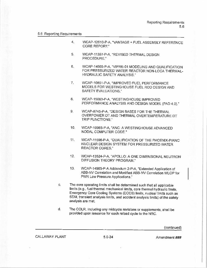
4. WCAP-12610-P-A, “VANTAGE + FUEL ASSEMBLY REFERENCECORE REPORT.”
5. WCAP-11397-P-A, “REVISED THERMAL DESIGNPROCEDURE.”
6. WCAP-14565-P-A, “VIPRE-Ol MODELING AND QUALIFICATIONFOR PRESSURIZED WATER REACTOR NON-LOCA THERMAL-HYDRAULIC SAFETY ANALYSIS.”
7. WCAP-10851-P-A, “IMPROVED FUEL PERFORMANCEMODELS FOR WESTINGHOUSE FUEL ROD DESIGN ANDSAFETY EVALUATIONS.”
8. WCAP-1 5063-P-A, “WESTINGHOUSE IMPROVEDPERFORMANCE ANALYSiS AND DESIGN MODEL (PAD 4.0).”
9. WCAP-8745-P-A, “DESIGN BASES FOR THE THERMALOVERPOWER DT AND THERMAL OVERTEMPERATURE DTTRIP FUNCTIONS.”
10. WCAP-10965-P-A, “ANC: A WESTINGHOUSE ADVANCEDNODAL COMPUTER CODE.”
I I . WCAP-f I 596-P-A, “QUALI FICATION OF THE PHOENIX-P/ANCNUCLEAR DESiGN SYSTEM FOR PRESSURIZED WATERREACTOR CORES.”
12. WCAP-13524-P-A, “APOLLO: A ONE DiMENSIONAL NEUTRONDIFFUSION THEORY PROGRAM.”
13. WCAP-14565-P-A Addendum 2-P-A, “Extended Application ofABS-NV Correlation and Modified ABB-NV Correlation WLOP forPWR Low Pressure Applications.”
C. The core operating limits shall be determined such that all applicablelimits (e.g., fuel thermal mechanical limits, core thermal hydraulic limits,Emergency Core Cooling Systems (ECCS) limits, nuclear limits such as5DM, transient analysis limits, and accident analysis limits) of the safetyanalysis are met.
d. The COLR, including any midcycle revisions or supplements, shall beprovided upon issuance for each reload cycle to the NRC.
(continued)
CALLAWAY PLANT 5.0-24 Amendment ##4t

Enclosure to ULNRC-062 I 5Attachment 4Page 1 of 27
ATTACHMENT 4
PROPOSED FSAR CHANGES(for information only)

-
ir
CALL
AWAY
-SP
TABL
EI .6-2(Sheet21)
Westinghouse
FSAR
Topical
Revision
Section
Subm
itted
Review1
Report N
Qflue
Num
beReference
tolheNRC
Status
WCAP-14O4O
-NPA
Methodology
Usedto
Develop
Cold
Rev.4
53.1.61
AOverpressureMitigationSystem
SetpointsandRCSHeatupand
Cooldow
nLimitCurves
WCAP-15f51
Westinghouse
ArchivedReactorVessel
12/98
5.3.1.6.1
Materials
WCAP-12472-P-A
Addendum
1-A
Rev.
04.3.2.2.7
1/00
AWCAP1
5400
AnalysisofCapsule
Xfro
mCallaway
Unit6/00
5.3.4
A1ReactorVessel R
adiationSurveitlance
Table5.3-10
Program
Rev.
OL-20c
9/14

CALLAWAY - SP fNo changes to this pa
4.4 THERMAL AND HYDRAULIC DESIGN
4.4.1 DESIGN BASES
The overall objective of the thermal and hydraulic design of the reactor core is to provideadequate heat transfer which is compatible with the heat generation distribution in thecore such that heat removal by the reactor coolant system or the emergency core coolingsystem (when applicable) assures that the following performances and safety criteriarequirements are met:
a. Fuel damage (defined as penetration of the fission product barrier, i.e., thefuel rod clad) is not expected during normal operation and operationaltransients (Condition I) or any transient conditions arising from faults ofmoderate frequency (Condition II). It is not possible, however, to precludea very small number of rod failures. These will be within the capability ofthe plant cleanup system and are consistent with the plant design bases.
b. The reactor can be brought to a safe state following a Condition lit eventwith only a small fraction offuel rods damaged (see above definition)although sufficient fuel damage might occur to preclude resumption ofoperation without considerable outage time.
C. The reactor can be brought to a safe state and the core can be keptsubcritical with acceptable heat transfer geometry following transientsarising from Condition IV events.
In order to satisfy the above criteria, the following design bases have been estabtishedfor the thermal and hydraulic design of the reactor core.
Note: For purposes of description of the thermal and hydraulic design of the reactorcore, specific information is presented in this section, with figures and tables provided.Though these exhibits may be based on a particular cycle, they should be regarded astypical and presented for illustration purposes only. Thermal and hydraulic design of thereactor core and verification of expected operation within acceptance criteria iscompleted each cycle per plant procedures and documented per the requirement ofTechnical Specification 5.6.5 and 5.6.6.
4.4.1 .1 Departure from Nucleate Boiling Design Ba&s
Basis
There will be at least a 95 percent probability that DNB will not occur on the limiting fuelrods during normal operation, operational transients, and any transient conditions arisingfrom faults of moderate frequency (Conditions I and II events), at a 95 percentconfidence level.
4.4-1 Rev. QL-20. 11/13

CALLAWAY - SP
Discussion
In this application the WRB-f (OFA) and WRB-2 (V5N+) correlations (Ref. I , 2, 86) aeemployed. OFA fuel is no longer_usedinCaNawa reaçtorcores.
outside the range of applicabityoftlWRBcoFFtiojI I 3 for Fo(those accidents which kse-4he ‘N 3-DN8 errelation the DNBR correlation limitsABB-NV ar 44 (RCCA Bank Withdrawal from Subcritical) and 4-4ê I 8 for wLöP
Failure at less than 1000 psia; see Reference 83). The RCCA Bank Mthdrawal fromSubcritical analysis in Section 15.4.1 uses the WRB-2 correlation, except for below the
[jJJrstmixinvane grid location (grid 2 on Figures 4.2-2, 4.2-2B and 4.2-2C) where theLJ corr&a1iönust-be used (NBR14ef1-3) Aeafty analycic-DNBR-kmit of I 43 i
uced4eFV4UaReW1thThe-WR&4erre1aben for now41DR1ranient suckas4heRGGABank WithdrawI4rom Subcritical (beveihe firstmrngvnd)and the
Temperature; ThflfetyGRa1yiCDNBRlifn#G4ef4oR RTDP•tranetentc aralyzedwith4heW 3 cor slat af:-ARGGABaFk1Mthraw1-fFeH%SubcncaIbe1ow thefirst ffig-vane grid) aid4-(MeiwSteamneace k-4OGG-p6ia)
The design method employed to meet the DNB design basis is the revised thermaldesign procedure (RTDP), Reference 3. With RTDP methodology, uncertainties in theplant operating parameters, nuclear and thermal parameters, fuel fabricationparameters, computer codes and DNB correlation predictions are combined statisticallyto obtain the overall DNB uncertainty factor which is used to define the design limitDNBR that satisfies the DNB design criterion. Since the parameter uncertainties areconsidered in determining the RIDP design limit DNBR values, the plant safety analysesare performed using input parameters at their nominal values without uncertainties. Thisprocedure is illustrated in Figure 2-1 of Reference 3.
The RTDP design limit DNBR values are I .22 and I .21 for the typical and thimble cells,respectively. To maintain DNBR margin to offset DNB penalties such as those due tofuel rod bow (paragraph 4.4.125) and the lower plenum flow anomaly (paragraph4.4.2.2.6), the RTDP safety analyses were performed to DNBR limits higher than thedesign limit DNBR values. The difference between the design limit DNBRs and thesafety analysis limit DNBRs results in available DNBR margin. The net DNBR margin,after consideration of all penalties, is available for operating and design flexibility.
The standard thermal design procedure (STDP) is used for those analyses where RTDPis not applicable. In the STDP method, the parameters used in the analysis are treatedin a conservative way from a DNBR standpoint. The parameter uncertainties are applieddirectly to the plant safety analysis input values to give the lowest DNBR. The DNBRlimit for STDP is the appropriate DNB correlation limit increased by sufficient margin tooffset the applicable DNBR penalties.
The design DN8Rs are used as the bases for Technical Specifications, and forconsideration in evaluations completed in accordance with 10 CFR 50.59.
4.4-2 Rev. OL-20I I /13

CALLAWAY - SP
4.4.2.2 Critical Heat Flux Ratio or Departure from Nucleate
Boiling Ratio and Mixing Technology
The minimum DNBRs for the rated power, design overpower, and anticipated transientconditions are given in Table 4A-1 . The minimum DNBR in the limiting flow channel willbe downstream of the peak heat flux location (hot spot) due to the increased downstreamenthalpy rise.
DNBRs are calculated by using the correlation and definitions described in Sections4.4.2,2.1 and 442.22. The VIPRE-Of computer code (discussed in Section 4.4.45.1)is used to determine the flow distribution in the core and the local conditions in the hotchannel for use in the DNB correlation. The use of hot channel factors is discussed inSection 4.4.4.3.1 (nuclear hot channel factors) and in Section 4A22A (engineering hotchannel factors).
4.4.2.2.1 Departure from Nucleate Boiling Technology
The W-3 correlation, and several modifications of it, have been used in WestinghouseCHF calculations. The W-3 correlation was originally developed from single tube data(Ref. 7), but was subsequently modified to apply to the 0.422 in. O.D. rod “R” grid(Ref. 8) and “L” grid (Ref. 9) as well as the 0.374 in. O.D. (Ref. 10 and 11) rod bundledata. These modifications to the W-3 correlation have been demonstrated to beadequate for reactor rod bundle design. [7 alternative correlations are discussed
folIowing the WRB-2 correlation information.The WRB-1 (Ref. 1) correlation was devilbèd bidifüshi1Tàn the Ia ribank ofmixing vane grid rod bundle CHF data (over 1100 points) that Westinghouse hascollected. The WRB-1 and WRB-2 correlations, based on local fluid conditions,represent the rod bundle data with better accuracy over a wider range of variables thanthe previous correlations. These correlations account directly for both typical andthimble cold wall cell effects, uniform and nonuniform heat flux profiles, and variations inrod heated length and in grid spacing.
The applicable range of variables (WRB-f correlation) is:
Pressure 1440P249OpsiaILocal mass velocity o. < Gi0d 3.7 lb/ft2-hr
Local quality O.2 X0 0.3
Heated length, inlet to CHF location Lh 14 feet
Grid spacing I 3 sp 32 inches
Equivalent hydraulic diameter 0.37 de 0.60 inches
4.4-5 Rev. OL-20. 11/13

CALLAWAY - SP
Equivalent heated hydraulic diameter 0.46 dh 0.59 inches
Figure 4.4-2A shows measured critical heat flux plotted against predicted critical heatflux using the WRB-1 correlation.
Critical heat flux tests which model the I 7 x I 7 OFA have been performed with theresults described in detail in Reference 5. It was concluded that the CHF characteristicsof the I 7 x I 7 OFAN5N+ designs are not significantly different from those of the I 7 x I 7STD design, and can be adequately described by the “R” grid form of the WRB-1correlation. Furthermore, the new data can be incorporated into the “R” grid database.The WRB-2 correlation (Ref. 86) was developed to take credit for the V5 IntermediateFlow Mixing (IFM) grid design. Figure 4.4-2b shows measured critical heat flux plottedagainst critical heat flux using the WRB-2 correlation.
The applicable range of parameters for the WRB-2 correlation is as follows::
Pressure 1440P249Opsia.Local Mass Velocity ‘-..--‘ o.€ e i 06 3.7 lb/ft2-h
Local Quality -0.1 X10 0.3
Heated Length, inlet to CHF location Lh 14 ft
Grid Spacing 70 sp 26 in.
Equivalent Hydraulic Diameter 0.37 de 0.51 inches
Equivalent Heated Hydraulic Diameter 0.46 dh 0.59 inchesIINSERTA j
TheW-3D83r{%atIon +aphe toeetditioriwktch aeu1&ide theanges-oararneterc for-theWR land RS2-correiauons
4.4.2.2.2 Definition of Departure from Nucleate Boiling Ratio
The DNB heat flux ratio (DNBR) as applied to this design when all flow cell wafts areheated is:
DNBR =lDNB,N
4.4-6 Rev. OL-20. 11/13

CALLAWAY - SPReplacewith:
83. LelUich, A., et. at., “Extended Application ofABB-NV Correlation and ModifiedAB8NV Correlation WLOP for PWR Low Pressure Applications,”WCAP-1 4565-P-A Addend urn 2-P-A, April 2008.
_____________________
Boiling Flow Instabilities in a Cross-C3ected Four-Parallel-Channel UpfiowSystem,” Proc of 5th International HepI Transfer Conference, Tokyo, September3-7, 1974.
/
78. Kao, H. S., Morgan, C. D., and,Arker, W. B., “Prediction of Flow Oscillation inReactor Core Channel,” TrØ. ANS Vol. 16, pgs. 212-213, 1973.
79. Tong, L. S., “Prediction 9f’beparture from Nucleate Boiling for an AxiallyNon-Uniform Heat F9’Distribution,” J. Nucl. Energy. j, 241-248 (1967).
80. Ohtsubo, A., andøiwashi, S., “Stagnant Fluid due to Local Flow Blockage,” LNuct. Sci. Tecpi, No. 7, p.p. 433-434, (1972).
81 . Basmer, P,%rsh, D. and Schultheiss, G. F., “Investigation ofthe Flow Pattern inthe ReciWulation Zone Downstream of Local Coolant Blockages in Pin Bundles,”
P!Ltschaft, iZ No. 8, p.p. 416-417, (1972). (In German).
82. T. M., Meyer, C. E. and Sheicheck J., “Analysis of Data from the Zion (Unit, TH1NC Verification Test “ WCAP-8453-A, May, 1976,
V
_____________
83 t:e#ef4FeffiA_G:1:ha4a+wfNRG*4ew4 4oion (Westwghoue, JaAuay44-49891-SubjeGt;4ooeptance’fofWGAP-22&1(PfopnetaFy) a[WCAP9227 (NoPcpnetry) ReactorCereRepGRe4oEx6essIve secerbryStean Re1eaee
84. Miller, R. W., et. al, “Relaxation of Constant Axial Offset Control FQ SurveillanceTechnical Specification,” WCAP-10216-P-A, Rev. 1, Februaruy 1994.
85. Deleted.
86. Davidson, S. L., (Ed.), “VANTAGE 5 Fuel Assembly Reference Core Report “,WCAP-f 0444-P-A, September 1 985 (Westinghouse Proprietary); WCAP I 0444Addendum 1-A. “Reference Core Report Vantage 5 Fuel Assembly”, NRCAcceptance Letter dated 3/12/86.
87. Hill, K. W., Motley, F. E., Cadek, F. F., and Castulin, J. E., “Effects on Critical HeatFlux of Local Heat Flux Spikes on Local Flow Blockage in Pressurized WaterReactor Rod Bundles,” ASME Paper 74-WNBT-54, August 1 2, 1974.
88. Stewart, C. W., et at., “VIPRE-Ol : A Thermal-Hydraulic Code for Reactor Cores,”Volume 1-3 (Revision 3, August 1989), Volume 4 (April 1987), NP-2511-CCM-A,Electric Power Research Institute.
4.4-42 Rev. OL-2011/13

INSERTAW-3 Alternative Correlation
The ABB-NV and WLQP, W-3 Alternative correlations, are based exclusively on DNB data fromrod bundle tests. They have a wider applicable range and are more accurate than the W-3correlation for the prediction of margin to DNB. They are used for DNBR calculations as analternative to the W3 correlation and supplement the primary WRB-2 DNB correlation.
The ABB-NV correlation was originally developed for fuel designs of Combustion Engineeringdesigned Pressurized Water Reactors (PWRs) based on a linear relationship between theCritical Heat Flux (CHF) and local quality. The correlation includes the following parameters:pressure, local mass velocity, local equilibrium quality, distance from grid to CHF location,heated length from inlet to CHF location, and heated hydraulic diameter of the subchannel.Supplemental rod bundle data evaluation confirms that ABB-NV, with a 95/95 correlation limit ofI .1 3, is applicable to the fuel region below the first mixing vane grid for fuel designs that arecompatible with Westinghouse designed PWRs (Reference 93). Figure 4.4-3a shows measuredcritical heat flux plotted against predicted heat flux using the ABB-NV correlation.
The applicable range of the ABS-NV correlation is:
Pressure (psia) : 1750 to 2415Local Mass Velocity (Mlbm/hr-ft2) : 0.8 to 3.16Local Quality (fraction) : < 0.22Heated Length, inlet to CHF location (in.) : 48 (minimum) to I 50Heated Hydraulic Diameter Ratio : 0.679 to I .08Grid Distance (inj : 7.3 to 24
The WLOP correlation is a modified ABB-NV correlation specifically developed for low pressureconditions and extended flow range to cover low pressure/low flow conditions. Modifications toABB-NV were made based on test data from rod bundles containing non-mixing vane grids.The WLOP correlation with a 95195 DNBR limit has also been validated with test data from rodbundles containing mixing vane grids (Reference 93). The WLOP correlation with a 95/95DNBR limit of 1.18 has also been validated with test data from rod bundles containing mixingvane grids (Reference 93). Figure 4.4-3b shows measured critical heat flux plotted againstpredicted heat flux using the WLOP correlation.
The applicable range of the WLOP correlation is:
Pressure (psia) : 185 to 1800Local Mass Velocity (Mlbm/hr-ft2) : 0.23 to 3.07Local Quality (fraction) : < 0.75Heated Length, inlet to CHF location (in.) : 48 (minimum) to 168Heated Hydraulic Diameter Ratio : 0.679 to I .00Grid Spacing Term (Reference 93) : 27 to 115
Change Reference 83:
83. Leidich, A., et. al., “Extended Application ofABB-NV Correlation and Modified ABB-NVCorrelation WLOP for PWR Low Pressure Applications,” WCAP-14565-P-A Addendum2-P-A, April 2008.

14
t4
Figure 44-3aMeasured Versus Predicted Critical Heat Flux — ABS-NV Correlation
Figure 4.4-3bMeasured Versus Predicted Critical Heat Flux — WLOP Correlation
a:2•••• -
One-Sided 95/95Tolernncc Limit focDNBR9SofI IS
. Data ri WCAPl4565-P-A, Addendum I-A[QuaIification Test Data wti viPi J
12
E
94
02
.
One-Sided 95 95 DNBRTolerance Limit forDNBR595of1 13
0 • -•-— .. “—:—-.. .
0 02 04 06 08 12
Predicted CIIF, MBtuThr-ft2
.
OS
!
04
02
00 02 04 0ó 14
VLOP Predicted CIIF, MBIu/br-ft1
CALLAWAY - SP
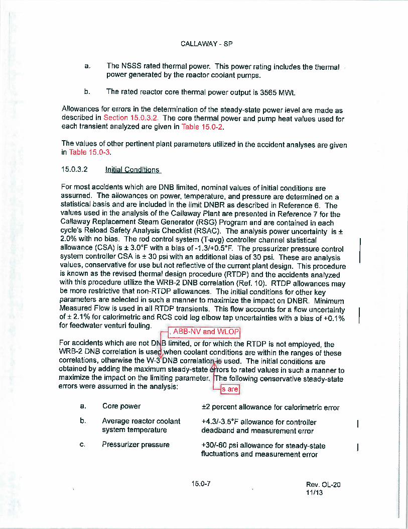
a. The NSSS rated thermal power. This power rating includes the thermalpower generated by the reactor coolant pumps.
b. The rated reactor core thermal power output is 3565 MWt.
Allowances for errors in the determination of the steady-state power level are made asdescribed in Section 1 5.O32. The core thermal power and pump heat values used foreach transient analyzed are given in Table 15.0-2.
The values of other pertinent plant parameters utilized in the accident analyses are givenin Table 1 5.0-3.
15.0.3.2 Jnitial Conditions
For most accidents which are DNB limited, nominal values of initial conditions areassumed. The allowances on power, temperature, and pressure are determined on astatistical basis and are included in the limit DNBR as described in Reference 6. Thevalues used in the analysis of the Callaway Plant are presented in Reference 7 for theCallaway Replacement Steam Generator (RSG) Program and are contained in eachcycle’s Reload Safety Analysis Checklist (RSAC). The analysis power uncertainty is ±2.0% with no bias. The rod control system (T-avg) controller channel statisticalallowance (CSA) is ± 3.0°F with a bias of -1 .3/+0.5°F. The pressurizer pressure controlsystem controller CSA is ± 30 psi with an additional bias of 30 psi. These are analysisvalues, conservative for use but not reflective ofthe current plant design. This procedureis known as the revised thermal design procedure (RTDP) and the accidents analyzedwith this procedure utilize the WRB-2 DNB correlation (Ref. I 0). RTDP allowances maybe mote restrictive that non-RTDP allowances. The initial conditions for other keyparameters are selected in such a manner to maximize the impact on DNBR. MinimumMeasured Flow is used in all RTDP transients. This flow accounts for a flow uncertaintyof ± 2.1 % for calorimetric and RCS cold leg elbow tap uncertainties with a bias of ÷0.1%for feedwater venturi fouling.
For accidents which are not DS limited, or for which the RTDP is not employed, theWRB-2 DNB correlation is us%when coolant conditions are within the ranges of thesecorrelations, otherwise the W-3 DNB correlation-i& used. The initial conditions areobtained by adding the maximum steady-state ors to rated values in such a manner tomaximize the impact on the limiting parameter. The following censervative steady-stateerrors were assumed in the analysis: are
a. Core power ±2 percent allowance for calorimetric error
b. Average reactor coolant ÷4.31-3.5°F allowance for controllersystem temperature deadband and measurement error
C. Pressurizer pressure +30/-60 psi allowance for steady-statefluctuations and measurement error
15.0-7 Rev. OL-20.
11/13

CALLAWAY - SP Tàchanges.
d_ Reactor coolant flow
I 5.0.3.3 Power Distribution
thermal power level.
1 5.0-8
I
Thermal design flow is assumed and nosteady-state errors are applied
Table 15.0-2 summarizes the principal initial conditions, computer codes used, DNBcorrelations, and thermal hydraulic methods. Other accident specific initial conditionsare given in those sections describing the accident. The level of steam generator tubeplugging assumed for each transient is listed in Table 15.0-2.
IOutofscope.The transient response of the reactor system is dependent on the initial powerdistribution. The nuclear design of the reactor core minimizes adverse powerdistributions through the placement of fuel assemblies, control rods, and operatinginstructions. Power distribution may be characterized by the radial factor (FH) and thetotal peaking factor (FQ). The peaking factors limits are given in the COLR.
For transients which may be DNB limited, the radial peaking factor is of importance. Theradial peaking factor increases with decreasing power level due to rod insertion. Thisincrease in FH is included in the core limits illustrated in Figure 1 5.0-1 . All transientsthat may be DNB limited are assumed to begin with a FAH consistent with the design
For transients which may be overpower limited, the total peaking factor (F0) is ofimportance. All transients that may be overpower limited are assumed to begin withplant conditions, including power distributions which are consistent with or conservativewith respect to reactor operation, as defined in the Technical Specifications.
The axial power shape discussed in Reference 9 is used in the DNBR calculation fortransients analyzed at full power. It is also the limiting power shape calculated or allowedfor accidents initiated at non-full power or asymmetric RCCA conditions.
The radial and axial power distributions described above are input to the VIPRE code, asdescribed in Section 4.4.
For overpower transients that are slow with respect to the fuel rod thermal time constant,for example the chemical and volume control system malfunction that results in adecrease in the boron concentration in the reactor coolant incident that fasts manyminutes, and the excessive increase in secondary steam flow incident, which may reachequilibrium without causing a reactor trip, the fuel rod thermal evaluations are performedas discussed in Section 4.4. For overpower transients that are fast with respect to thefuel rod thermal time constant, for example, the uncontrolled RCCA bank withdrawalfrom subcritical or low power startup conditions and RCCA ejection incidents which resultin a large power rise over a few seconds, a detailed fuel transient heat transfercalculation must be performed.
Rev. OL-2011/13

EVEN
T
Increase
inheatremoval
bythesecondarysystem
Decreaseinfeedwater
temperature
Increase
infeedwater
flow
maIwnli-(HFPCases)
Case)
Excessive
increase
insecondarysteam
flow
Inadvertentopening
ofSIG
reliefor safetyvalve
Steamsystem
piping
failure
CALL
AWAY
-SP
Rev.OL-20
11/13
Increase
infeedwater
flow
15.1
TABL
E15.0-2
SUMMARY
OF
NITIALCONDITIONSANDCOMPU
TERCODES
REACT
IViTYCOEF
FICIENTS
COMPU
TER
MODER
ATO
RMODER
ATO
RREV
ISED
iNITIALCORE
CODES
DEN
SITY
TEMPE
RATU
RE
DNB
THER
MALD
ESIGN
THER
MAL
USE
D(iiclgm
/cc)
(PCM/F)
DOPPLE
RCORREL
ATION
PROCED
URE
POWER
(%RTP
)
RET
RAN
0.43
NA
Uppercurveof
WRB
-2Yes
100
Figure
15.0-2
RET
RAN
043
NA
Uppercurveof
WRB
-2Yes
100
Figure
15.0-2
RET
RAN, V
IPRE
Functionof
NASee
Figure
151-14
No
0moderatordensity
SeeSection151.3fora
llassumptions
SeeSection15.1.4forall
assumptions
RET
RAN
Functionof
NA
SeeFigure
15.1-14
No
0ANC
moderatordensity
(Subcritical)
VIPRE
RET
RAN
NA
I5.2
Decreaseinheatremoval
bythesecondarysystem
Loss
ofexternalelectricalload
and/or
turbinetrip
DNBCase!PressureCase
Loss
ofnon-em
ergencyac
tostationauxiliaries
Lossofnormalfeedwater
flow
Feedwatersystem
pipe
break
Uppercurveof
WRB-2INA
Agure
150-2
RET
RAN
RETR
AN
RET
RAN
0 0 0 0
NA
NA NA
Yes/No
100/102
Lowercurveof
NA
No
102
Figure
150-2
Lowercurveof
NANA
102
Figure150-2
Lowercurveof
NA
NA
102
Figure150-2

CALL
AWAY
-SP
TABL
E15.0-2
(Sheet
2)
Increaseln1
feedwater
flow
jREA
CTO
RRE
ACT
OR
EQUIVALE
NT
COOLA
NT
VES
SEL
VES
SEL
PRES
SURIZER
S/GTU
BEFU
LLPO
WER
PUMP
HEAT
COOLA
NT
I-AVG
PRES
SURIZER
WATE
RFE
EDWATE
RPL
UGGING
STEA
DY
EVEN
T(M
VVL)
FLOW
(gpm
)(CF)
PRES
SURE(PSIA)
LEVE
L%span
TEMP(CF)
LEVE
LST
ATEFA
HEQ
151
Increase
inheatremoval
bythesecondarysystem
Decreaseinfeedwater
14382,630
588.4
2250
60446
0%NA
NAtemperature
IIncreaseinfeedwater
flow
14382630
588.4
2250
60446
0%NA
NA
ImaitJfltieR(HFP
Cases)
HZP
Case)
14374400
557
2250
25100
0%NA
NA
Excessive
increase
inSeeSechon
1 5.13
forall
assumptions
secondarysteam
flow
nadvertentopeningofS/G
SeeSection
1 5.1Afor a
llassumptions
relief orsafetyvalve
Steamsystem
piping
failure
14374400
557
2250
25100
0%NA
NA
I5.2
Decreaseinheatremoval
bythesecondarysystem
Loss
ofexternalelectrical
load
and/or
turbinetrip
DNBCase
14382,630
588.4
2250
65390
5%NA
NA
PressureCase
14374400
585.4
2190
65390
5%NA
NA
Loss
ofnonemergencyac
20374400
567.2
2190
43446
0%NA
NAtostationauxiliaries
Loss
ofnormalfeedwater
20374400
567.2
2190
43446
0%NA
NAflow
Feedwatersystem
pipe
20374400
5927
2190
65446
5%NA
NAbreak
Rev.
OL-20
11/13

CALL
AWAY
-SP
TABL
E15.0-2(Sheet
3)
REACT
IVITYCOEF
FICIENTS
REV
ISED
THER
MAL
INITIALCORE
DNB
DES
IGN
THER
MAL
DOPPLE
RCORREL
ATiON
PROCED
URE
POWER
(%RTP
)
RCCAmisopecahon
(dropped
LOFT
RAN
rod)
VIPRE
0Lowercurveof
Figure150-2
0Lowercurveof
Figure150-2
0LowerCurve
ofFigure150-2
Upper
&lower
WRB-2
curves
ofFigure
1&0-2
NA
WRB-2
YES
100 60 10
YES
100
Rev.
OL-20
11/13
EVEN
TCOMPU
TER
CODES
USE
D
MODER
ATO
RDEN
SITY
fiMcigm
/cc)
MODER
ATO
RTE
MPE
RATU
RE
(PCMI’F)
NA NA
NA
I5.3
DecreaseinRCSflowrate
Partial/C
ompleteloss
ofRET
RAN
forced
flow
VIPRE
Reactor
coolantpumplocked
RET
RAN
rotor(DNBevaluation)
VIPRE
Reactorcoolantpiielocked
RET
RAN
rotor(peakpressure)V
VIPRE
15.4
Reactivity
andpower
distributionanom
aliestpum
pUncontrolledRCCAbank
TWINKLE
withdraw
alftom
subcritical
FACT
RAN
+i’$**€
UncontrolledRCCAbank
RET
RAN
withdraw
alatpower
WRB-2
YES
100
WRB-2
YES
100
NANO
102
fABB-Nv
I\{/
WRB-2W4
NO
0SeeSection
1541.2
SeeSection
1 541.2
SeeSection
1541.2
NA
NNO
NN+5
NN+5
NA
NA
Startupofan
inactiveloop
atan
incorrect tem
perature
RCCAejection
SeeSection154.4forallassumptions
1WNKLE
SeeSection
SeeSection
SeeSection
FACT
RAN
THINC
1548.2
15482
1548.2
NANA
102
CALLAWAY - SP
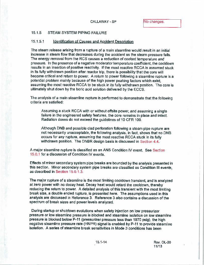
15.1.5 STEAM SYSTEM PIPING FAILURE
151 .5.1 Identification of Causes and Accident Description
15.1-14
[chanes.
The steam release arising from a rupture of a main steamline would result in an initialincrease in steam flow that decreases during the accident as the steam pressure falls.The energy removal from the RCS causes a reduction of coolant temperature andpressure. In the presence of a negative moderator temperature coefficient, the cooldownresults in an insertion of positive reactivity. If the most reactive RCCA is assumed stuckin its fully withdrawn position after reactor trip, there is possibility that the core willbecome critical and return to power. A return to power following a steamline rupture is apotential problem mainly because ofthe high power peaking factors which exist,assuming the most reactive RCCA to be stuck in its fully withdrawn position. The core isultimately shut down by the boric acid solution delivered by the ECCS.
The analysis of a main steamline rupture is performed to demonstrate that the followingcriteria are satisfied:
Assuming a stuck RCCA with or without offsite power, and assuming a singlefailure in the engineered safety features, the core remains in place and intact.Radiation doses do not exceed the guidelines of 10 CFR 100.
Although DNB and possible clad perforation following a steam pipe rupture arenot necessarily unacceptable, the following analysis, in fact, shows that no DNBoccurs for any rupture, assuming the most reactive RCCA stuck in its fullywithdrawn position. The DNBR design basis is discussed in Section 4.4.
A major steamline rupture is classified as an ANS Condition IV event. See Section1 5.0.1 for a discussion of Condition IV events.
Effects of minor secondary system pipe breaks are bounded by the analysis presented inthis section. Minor secondary system pipe breaks are classified as Condition Ill events,as described in Section 15.0.1.3.
The major rupture of a steamline is the most limiting cooldown transient, and is analyzedat zero power with no decay heat. Decay heat would retard the cooldown, therebyreducing the return to power. A detailed analysis of this transient with the most limitingbreak size, a double ended rupture, is presented here. The assumptions used in thisanalysis are discussed in Reference 3. Reference 3 also contains a discussion of thespectrum of break sizes and power tevels analyzed.
During startup or shutdown evolutions when safety injection on low pressurizerpressure or low steamline pressure is blocked and steamline isolation on low steamlinepressure is blocked below P-Il (pressurizer pressure less than 1970 psig), the highnegative steamline pressure rate (HNPR) signal is enabled by P-fl to provide steamlineisolation. A series of steamline break sensitivities in Mode 3 conditions has been
Rev. OL-201 1/13

CALLAWAY - SP
The following functions provide the protection for a steamline rupture:
2. Two out offour low pressurizer pressure signals
C. Redundant isolation of the main feedwater lines
15.1-15
INo changes.performed using the LQFTRAN code (Ref. 1) to investigate the response ofthe HNPRfunction below P-I I . Specifically, a spectrum of break sizes over a wide range of Mode 3temperatures has been considered. The results of this study demonstrate that automaticsteamline isolation is provided by the HNPR function for all but the smallest breaks forRCS temperatures from approximately the middle to the high end of the Mode 3 range.As the RCS temperatures is decreased below these values, the smaller break sizes areno longer automatically protected by the HNPR function. Finally, as the RCStemperature is reduced further, the HNPR function does not provide protection for anybreak size. This is consistent with the expected response of the protection functionsince, as the assumed RCS temperature is decreased, the initial steam generatorpressure decreases as well, making it less likely that the HNPR setpoint would bereached. It should be noted that steamline isolation can also be provided by acontainment pressure High-2 signal for breaks inside containment or by manual actionsperformed in accordance with established procedures. Furthermore, more restrictiveboration requirements for conditions below P-Il make the Mode 3 steamline breakscenario less limiting than the case analyzed from HZP conditions. More information onthis sensitivity study can be found in Reference 9. The analyses documented inReference 3 cover a spectrum of breaks, from HZP, partial power, and full power,including cases where the MSIVs do not close until either a containment pressure signalis generated or they are manually isolated. Reference 3, which was approved by theNRC in Reference 6, concludes that the HZP double-ended steamline break at EOLconditions discussed in Section 1 5.1 .5.2 is a limiting case that conservativelydemonstrates the compliance ofWestinghouse PWRs with all applicable steamlinebreak acceptance criteria.
a. Safety injection system actuation from any of the following:
I . Two out of three low steamline pressure signals in any one loop
3. Two out ofthree high-I containment pressure signals
b. The overpower reactor trips (neutron flux and AT) and the reactor tripoccurring in conjunction with receipt of the SIS.
Sustained high feedwater flow would cause additional cooldown.Therefore, in addition to the normal control action which will close the mainfeedwater valves following reactor trip, an $15 will rapidly close allfeedwater isolation valves. This signal would also trip the main feedwaterpumps, close the pump discharge valves, and close the feedwater controlvalves. The success of this analysis is not predicated on the operation of
Rev. OL-2011/13

CALLAWAY - SP
d. Trip of the main steam isotation valves on:
151.5.2 Analysis ofEffects and Consequences
Method of Analysis
15.1-16
tNo changes. Ithe main feedwater pumps nor the pump discharge valves (see Section7.1.25.2 and Figure 7.2-1 sheets 13 and 14). The feedwater controlvalves are primary success path equipment for secondary side piperuptures analyzed in Section 62.
I . Safety injection system actuation derived from two out of three lowsteamline pressure signals in any one loop (above Permissive-Il)
2. Two out of three high-2 containment pressure signals
3. Two out ofthree high negative steamline pressure rate signals inany one loop (used only during coofdown and heatup operations,below Permissive-Il with Tavg greater than 400°F)
Isolation valves are provided in each steamline. For breaks down-stream ofthe isolationvalves, closure ofall valves would completely terminate the blowdown. For any break, inany location, no more than one steam generator would experience an uncontrolledblowdown, even if one of the isotation valves fails to close. A description of steamlineisolation is included in Section 10.3. In the analysis, these valves are assumed to fullyclose within 1 7 seconds upon receipt of a steamline isolation signal following a largebreak in a steamline. The 17 seconds includes a 2 second signal processing delayassumption. Additionally an engineering evaluation was completed to support anincrease in the main steam isolation valve stroke delay up to 60 seconds for steamgenerator pressures below that which corresponds to the P-fl permissive set point. Thisevaluation demonstrated that the acceptance criteria continue to be met for this scenario.More information on this engineering evaluation can be found in Reference 10.
Steam flow is measured by monitoring dynamic head in nozzles located in the steamgenerator outlet. The effective throat area of the nozzles is I .39 square feet, which isconsiderably less than the main steam pipe area; thus, the nozzles also serve to limit themaximum steam flow for a break at any location.
Table 15.1-2 lists the equipment required in the recovery from a steamline rupture. Notall equipment is required for any one particular break, since the requirements will vary,depending upon postulated break size and location. Design criteria and methods ofprotection of safety-related equipment from the dynamic effects of postulated pipingruptures are provided in Section 3.6.
The analysis ofthe steam pipe rupture has been performed to determine:
Rev. OL-2011/13
CALLAWAY - SP
15.1-17
INo changes.a. The core heat flux and RCS temperature and pressure resulting from the
cooldown fotlowing the steamtine break. The RETRAN code (Ref. 8) hasbeen used.
b. The thermal and hydraulic behavior of the core following a steam linebreak. A detailed thermal and hydraulic digital-computer code, VIPRE, hasbeen used to determine if DNB occurs for the core conditions computed initem a above.
The following conditions were assumed to exist at the time of a main steamline breakaccident:
a. End-of-life shutdown margin at no-toad, equilibrium xenon conditions, andthe most reactive RCCA stuck in its fully withdrawn position. Operation ofthe control rod banks during each burnup is restricted by the insertion limitssuch that addition of positive reactivity in a steamline break accident willnot lead to a more adverse condition than the case analyzed.
b. A negative moderator coefficient corresponding to the end-of-life roddedcore with the most reactive RCCA in the fully withdrawn position. Asdiscussed below, this event initiates from MODE 3 (hot standby)conditions. All control and shutdown banks are on the bottom (except forthe most reactive, stuck rod) since the analysis acceptance criteria aremore difficult to satisfy if the shutdown banks are initially assumed to beinserted. The variation of the coefficient with temperature and pressurehas been included. The keff versus temperature at 1 ,140 psia,corresponding to the negative moderator temperature coefficient used, isshown in Figure 15.1-11. The effect olpower generation in the core onoverall reactivity (due to Doppler feedback) is shown in Figure 15.1-14.
The core properties associated with the sector nearest the affected steamgenerator and those associated with the remaining sector wereconservatively combined to obtain average core properties for reactivityfeedback calculations. Further, it was conservatively assumed that thecore power distribution was uniform. These two conditions causeunderprediction of the reactivity feedback in the high power region near thestuck rod. The stuck rod is assumed in the region of the core of lowesttemperature. To verify the conservatism of this method, the reactivity, aswell as the power distribution, was checked for the limiting conditionsduring the transient for the cases analyzed.
This core analysis, performed with the ANC code, considered the Dopplerreactivity from the high fuel temperature near the stuck RCCA, moderatorfeedback from the high water enthalpy near the stuck RCCA, powerredistribution, and nonuniform core intet temperature effects. For cases inwhich steam generation occurs in the high flux regions of the core, the
Rev. OL-2011/13

CALLAWAY - SP
15.1-18
INo changes.effect of void formation was also included. It was determined that thereactivity employed in the kinetics analysis was always larger than thereactivity catculated, including the above local effects for the state points.These results verify conservatism, i.e. , underprediction of negativereactivity feedback from power generation.
C. Minimum capability for injection of boric acid solution corresponding to themost restrictive single failure in the ECCS. The ECCS consists of foursubsystems: 1) the passive SI accumulators, 2) the residual heat removalsystem, and 3) the safety injection system, and 4) the high head injectionsystem (centrifugal charging pumps). Only the high head injection system(one CCP) and the passive SI accumulators are modeled for the steamlinebreak accident analysis. See Table 15.1-5.
The actual modeling ofthe ECCS in RETRAN is described in Reference 8.No credit has been taken for the low concentration (0 ppm) borated water,which must be swept from the lines prior to the delivery of boric acidsolution to the reactor coolant loops.
For the cases where offsite power is assumed, the following sequence ofevents occurs. After the generation of the safety injection signal(appropriate delays for instrumentation, logic, and signal transportincluded), the appropriate valves begin to operate, and the high headsafety injection pump starts. In 27 seconds (2 seconds for 518 generation(sensor) delay, I 5 seconds to open RWST suction isolation valvesBN-LCV-112D and E, and JO seconds to close VCT outlet isofation valvesBG-LCV-112B and C after the RWST valves are fully open), the valves areassumed to be in their final position, and the pump is assumed to be at fullspeed. The volume containing the low concentration (0 ppm) boratedwater is swept away before the boric acid solution reaches the core. Thisdelay is included in the modeling (See Reference 7).
In cases where offsite power is not available, an additional 12-seconddelay is assumed to start the diesels.
d. Design value ofthe steam generator heat transfer coefficient, includingallowance for steam generator tube fouling.
e. Since the steam generators are provided with integral flow restrictors with aI .39-square-loot throat area, any rupture with a break area greater than1 .39 square feet, regardless of location, would have the same effect on theNSSS as the I .39-square-foot break. The following cases have beenconsidered in determining the core power and RCS transients:
I . Complete severance of a pipe, with the plant initially at hot standbyconditions, full reactor coolant flow with offsite power available.
Rev. OL-2011/13

Results
CALLAWAY - SP
Core Power and Reactor Coolant System Transient
15.1-19
[ihanes.
2. Case (1) with loss of offsite power simultaneous with the steamlinebreak and initiation of the safety injection signal. Loss of offsitepower results in reactor coolant pump coastdown.
Power peaking factors corresponding to one stuck RCCA and nonuniformcore inlet coolant temperatures are determined at end of core life. Thecoldest core inlet temperatures are assumed to occur in the sector with thestuck rod. The power peaking factors accountfor the effect ofthe localvoid in the region of the stuck control assembly during the return to powerphase following the steamline break. This void in conjunction with the largenegative moderator coefficient partially offsets the effect of the stuckassembly. The power peaking factors depend upon the core power,temperature, pressure, and flow, and, thus, are different for each casestudied.
The core parameters used for each of the two cases correspond to valuesdetermined from the respective transient analysis.
Both cases above assume initial hot zero power (HZP) conditions (Tavg557°F) at time zero since this represents the worst initial condition (asdiscussed in Section 1 5.1 .5.1). Should the reactor be just critical oroperating at power at the time of a steamtine break, the reactor will betripped by the normal overpower protection system when power levelreaches a trip point. Following a trip at power, the RCS contains morestored energy than at HZP, the average cootant temperature is higher thanat HZP, and there is appreciable energy stored in the fuel. Thus, theadditional stored energy is removed via the cootdown caused by thesteamline break before the HZP conditions of RCS temperature andshutdown margin assumed in the analyses are reached. After theadditional stored energy has been removed, the cooldown and reactivityinsertions proceed in the same manner as in the analysis, which assumesno-load condition at time zero. A spectrum of steamline breaks at variouspower levels has been analyzed in Reference 3.
g. In computing the steam flow during a steamline break, the Moody Curve(Ref. 2) for f(L/D) 0 is used.
The calculated sequence ofevents for both cases analyzed is shown in Table 15.1-1.
The results presented are a conservative indication of the events which would occur,assuming a steamline rupture, since it is postulated that all of the conditions describedabove occur simultaneously.
Rev. OL-2011/13

CALLAWAY - SP
Figures 15.1-15A through 15.f-IZB show the RCS transient and core heat flux followinga main steamfine rupture (complete severance of a pipe) at initial HZP conditions(case a).
Offsite power is assumed to be available so that full reactor coolant flow exists. Thetransient shown assumes an uncontrolled steam release from only one steam generator.Should the core be critical at near zero power when the rupture occurs, the initiation ofsafety injection by low steamline pressure will trip the reactor. Steam release from morethan one steam generator will be prevented by automatic trip of the isolation valves in thesteamlines by low steamline pressure signals, high-high containment pressure signals,or by high negative steamline pressure rate signals. Even with the failure of one valve,release is limited by main steam isolation valve closure for the other steam generatorswhile the one generator blows down.
As shown in Figure 15.1-16B, the core attains criticality with the RCCAs inserted (withthe design shutdown assuming one stuck RCCA) shortly before boron solution enters theRCS. The continued addition of boron results in a peak core power significantly lowerthan the nominal full power value.
The calculation assumes that the boric acid is mixed with, and diluted by, the waterflowing in the RCS prior to entering the reactor core. The concentration after mixingdepends upon the relative flow rates in the RCS and from the centrifugal charging pump(COP). The variation of mass flow rate in the RCS due to water density changes isincluded in the calculation, as is the variation offlow rate from the CCP due to changes inthe RCS pressure. The CCP flow calculation includes the line losses in the system aswell as the pump head curve.
Figures 15.f-18A through 15.1-203 show the salient parameters for case b, whichcorresponds to the case discussed above with the additional loss of offsite power at thetime the safety injection signal is generated. The CCP delay time includes 12 seconds tostart the diesel in addition to 27 seconds to start the centrifugal charging pump and openthe valves. Criticality is achieved later, and the core power increase is slower than in thesimilar case with offsite power available. The ability of the emptying steam generator toextract heat from the RCS is reduced by the decreased flow in the RCS. The peakpower remains well below the nominal full power value. See also Reference 7.
It should be noted that following a steamline break only one steam generator blows downcompletely. Thus, the remaining steam generators are still available for the dissipation ofdecay heat after the initial transient is over. In the case of loss of offsite power, this heatis removed to the atmosphere via the steamline atmospheric relief and safety valves.
Margin to Critical Heat Flux
A DNB analysis was performed for both of these cases. It was found that both cases hada minimum DNBR greater than the safety analysis limit value as discussed in Section4.4i .1 . The W4 DNBR correlation was used in this analysis see Reference 5 for the
F I/f\ (Reference 12). Historically, the W-31WL0P DNB correlation had been used;
15.1-20 Rev. OL-20. 11/13

CALLAWAY-SP
15.153 Radiological Consequences
15.1.5.3.1 Method Of Analysis
Assumptions and Conditions
I 5.1-21
1I_No changes. I
justification discussing the use of the W-3 correlation for low pressure applications,accepted by the NRC in Reference 6.
[Out of scope.15.1.5.3.1.1 Physical Model
The radiological consequences of a MSLB inside the containment are less severe thanthe one outside the containment because the radioactivity released will be held up insidethe containment, allowing decay and plateout of the radionuclides. To evaluate theradiological consequences due to a postulated MSLB (outside the containment), it isassumed that there is a complete severance of a main steamline outside thecontainment.
It is also assumed that there is a simultaneous loss of offsite power, resulting in reactorcoolant pump coastdown. The ECCS is actuated and the reactor trips.
The main steam isolation valves, their bypass valves, and the steamline drain valvesisolate the steam generators and the main steamlines upon a signal initiated by theengineered safety features actuation system under the conditions of high negativesteamline pressure rates, low steamline pressure, or high containment pressures. Themain steam isolation valves are installed in the main steamlines from each steamgenerator downstream from the safety and atmospheric relief valves outside thecontainment. The break in the main steamline is assumed to occur outside of thecontainment. The affected steam generator (steam generator connected to a brokensteamline) blows down completely. The steam is vented directly to the atmosphere.
Each of the steam generators incorporates integral flow restrictors, which are designedto limit the rate of steam blowdown from the steam generators following a rupture of themain steamline. This, in turn, reduces the cooling rate of the reactor coolant systemthereby reducing the return to power.
In case of toss of offsite power, the remaining steam generators are available fordissipation of core decay heat by venting steam to the atmosphere via the atmosphericrelief and safety valves. Venting continues until the reactor coolant temperature andpressure have decreased sufficiently so that the RHR system can be utilized to cool thereactor.
15.1.5.3.1.2
The major assumptions and parameters assumed in the analysis are itemized in Tables15.1-3 and 15A-1.
Rev. OL-2011/13

CALLAWAY - SF
15.1.53.3.2 Dose to Receptor atthe Exclusion Area Boundary and Low-PopulationZone Outer Boundary
The potential radiological consequences resulting from the occurrence of a postulatedMSLB have been conservatively analyzed, using asusmptions and models described.The total-body gamma doses due to immersion from direct radiation and the thyroid dosedue to inhalation have been analyzed for the 0-2 hour dose at the exclusion area
A boundary and for the duration of the accident (0 to 8 hrs) at the low-population zoneouter boundary. The results are listed in Table 15.1-4. The resultant doses are wellwithin the guideline values of I 0 CFR I 00. [put oi scopiJ
I 5. 1 .5.4 Conclusions [Nochanges. 1The analysis has shown that the criteria stated earlier inSection 15i .5,1 are satisfied.
Although DNB and possible clad perforation following a steam pipe rupture ace notnecessarily unacceptable and not precluded by the criteria, the above analysis showsthat the DNB design basis is met for any rupture, assuming the most reactive RCCAstuck in its fully withdrawn position.
A safety evaluation was performed to determine the impact of a potential increase in thestroke time of the feedwater isolation valves beyond the value assumed in the analyses(1 5 seconds) due to the installation of new valve actuators. It was concluded that theresults presented in this section for the zero power steamline break event are notadversely affected by this plant modification. As such, the reported results andconclusions remain valid.
15.1.5.5 Steam Line Break with Coincident Control Rod WithdrawaI[ut of scope.
This accident is no longer applicable to Callaway since automatic rod withdrawal is nolonger available.
15.1.5.6 Steam System Piping Failure at Full Power
15.1.5.6.1 Identification of Causes and Accident Description
A Steamline Rupture - Full Power Core Response transient is defined as a “break” thatresults in an increase in steam flow from one or more steam generators. A SteamlineRupture can result from:
. An inadvertent opening of a steam generator dump, safety or relief valve
. A rupture ofthe main steam piping
Increased steam flow from the steam generators causes an increase in the heatextraction rate from the reactor coolant system, resulting in a reduction of primary
15.1-25 Rev. OL-2011113
V

CALLAWAY - SP
e. Reactor Trip
Reactor Trip is initiated on one of the following signals, depending on the break size:
. Safety Injection following a Low Steam Pressure in any steam line, or
p OPAT in any two loops.
f. Turbine Trip
Turbine trip is initiated following reactor trip.
15.1.5.6.2.3 Results
The transient response for the Steamline Rupture - Full Power Core Response analysisis shown in Figures 15.1-21 through 15.1-26. Table 15.1-la gives the time sequence ofevents for the limiting break size of 0.87 ft2.
15.1.5.6.3 Conclusions
The analysis shows that the acceptance criteria stated above are satisfied with theA improved setpoints proposed as a result of the Callaway OThT and OPAl Margin
Recovery Program. The DNBR safety analysis limit is met, and there is no fuelcenterline melt. lOut of scope.
__1 5.1 .6 REFERENCES INochanges.I . Burnett, I. W. T., et al., “LOFTRAN Code Description,” WCAP-7907-P-A, April
1984.
2. Moody, F. S., “Transactions ofthe ASME, Journal of Heat Transfer” Figure 3,page 134, February 1965.
3. Hollingsworth, S. D. and Wood, D. C., “Reactor Core Response to ExcessiveSecondary Steam Releases,” WCAP-9226, Revision I , (Proprietary), February,1988, and WCAP-9227, Revision I , (Non-Proprietary), February 1998.
4. WCAP-1 I 397-P-A (Proprietary), WCAP-1 1 397-A (Non-proprietary), “RevisedThermai Design Procedure,” A. J. Friedland and S. Ray, April 1989.
5. Union Electric Letter to NRC, ULNRC-1258, dated 2-1 8-86.
6. Letter from A. C. Thadani (NRC) to W. J. Johnson (Westinghouse), January 31,1989, Subject: “Acceptance for Referencing of Licensing Topical Report,WCAP-9226-P (Proprietary) and WCAP-9227 (Non-Proprietary), Reactor CoreResponse to Excessive Secondary Steam Releases.”
15.1-29 Rev. QL-2011/13

CALLAWAY - SP
7* Union Electric Letter to NRC, ULNRC-1493, dated 416-87, approved by OLAmendment No. 22 dated May 4, 1987.
8. WCAP-148$2-P-A, Revision 0, “RETRAN-02 Modeling and Qualification forWestinghouse Pressurized Water Reactor NonLOCA Safety Analyses” April1999.
9. SCP-941 62, “Callaway ($CP) Mode 3 SLB Evaluation,” January 4, 1995.
10. SCP-07-19, “Main Steam isolation Valve (MSIV) Stroke Time Evaluation Phase 2Report Revision 0,” February 16, 2007.
1 1 . WCAP-1 4565-P-A (Proprietary), WCAP-1 5306-A (Non-Proprietary), “VIPRE-OlModeling and Qualification for Pressurized Water Reactor Non-LOCA Thermal-Hydraulic Safety Analysis,” Y. X. Sung, October 1999.
_J12. WCAP-14565-P-A Addendum 2-P-A (Proprietary), “Extended Applicationof ABB-NV Correlation and Modified ABB-NV Correlation WLOP for PWR LowPressure Applications,” A. Leidich, et al., April 2008.
1 5. 1 -30 Rev. OL-2011/13

CALLAWAY - SP
TABLE 151-1 (Sheet 2)
TimeAccident
Excessive increase in secondarysteam flowI . Manual reactor control
(minimum moderatorfeedback)
2. Manual reactor control(maximum moderatorfeedback)
3 Automatic reactor control(minimum moderatorfeedback)
4 Automatic reactorcontrol (maximummoderator feedback)
[2t of scope. jSteam system piping failureI . Case I (offsite power
available)
[chanes. I
2. Case 2 (concurrent loss ofoffsite power)
EventFeedwater isolation valves closeautomatically
I 0-percent step load increase
Equilibrium conditions reached*10-percent step load increase
Equilibrium conditions reached*10-percent step load increase
Equilibrium conditions reached*10-percent step loadincrease
Equilibrium conditions reached*
Steamline rupturesLow steamline pressure setpointreached in faulted loopLow steamline pressure setpointreached in intact loopsSteamline isolation occursCriticality attainedSI actuationBoron reaches coreSteamline rupturesLow steamline pressure setpointreached in faulted loopLow steamline pressure setpointreached in intact loopsSteamline isolation occursCriticality attainedSI actuation
I 000.0
500.0
I 50
I0.510
2.059
17.510232810000.510
2.059
17.5103040
Rev. OL-2011/13
106.7
0.0
I

CALLAWAY - SP
TABLE 15.1-1 (Sheet 3)
[i:io changes.
Accident
* Approximate time only
EventBoron reaches core
Time(s112
Rev. OL-2011/13