Cisco Unified Wireless IP Phone 7920 for Cisco Unified CallManager

Call Manager 7.x integration with Exchange 2010
In general, the steps required to configure Cisco CallManager to work with Exchange UM 2010 can be summarized as:
Create A SIP trunk. Define route pattern for Exchange UM. Configure appropriate coverage paths for UM-enabled users.
In this section, we show how the configuration can be done via the CallManager web-based administration interface. We shall use the convention “x y” to indicate “click on x followed by click on y”.
1
STEP 1: CHECK LICENSING
On the administration UI, go to “System Licensing License Unit Report”. Confirm that the license file is uploaded and the status indicates Ready.
Figure 1
2

STEP 2: CONFIGURING CISCO UNIFIED CALLMANAGER, CALLMANAGER GROUPS, REGION AND DEVICE POOL
Go to “System Cisco Unified CallManager”. Use the default configuration for the Cisco Unified CallManager (Figure 2).
Figure 2
Go to “System Cisco Unified CallManager Groups”. Use default configuration for the Cisco CallManager Group (Figure 3).
Figure 3
3

Go to “System Region”. Use default configuration for the region (Figure 4).
Figure 4
4

Go to “System Device Pool”. Use default configuration for the device pool (Figure 5).
Figure 5
5

STEP 3: CREATE A NEW SIP TRUNK
Go to “Device Trunk Add New” to create a new SIP trunk with the following parameter settings (Figure 6):
Trunk Type = SIP Trunk Device Protocol = SIP
Figure 6
6
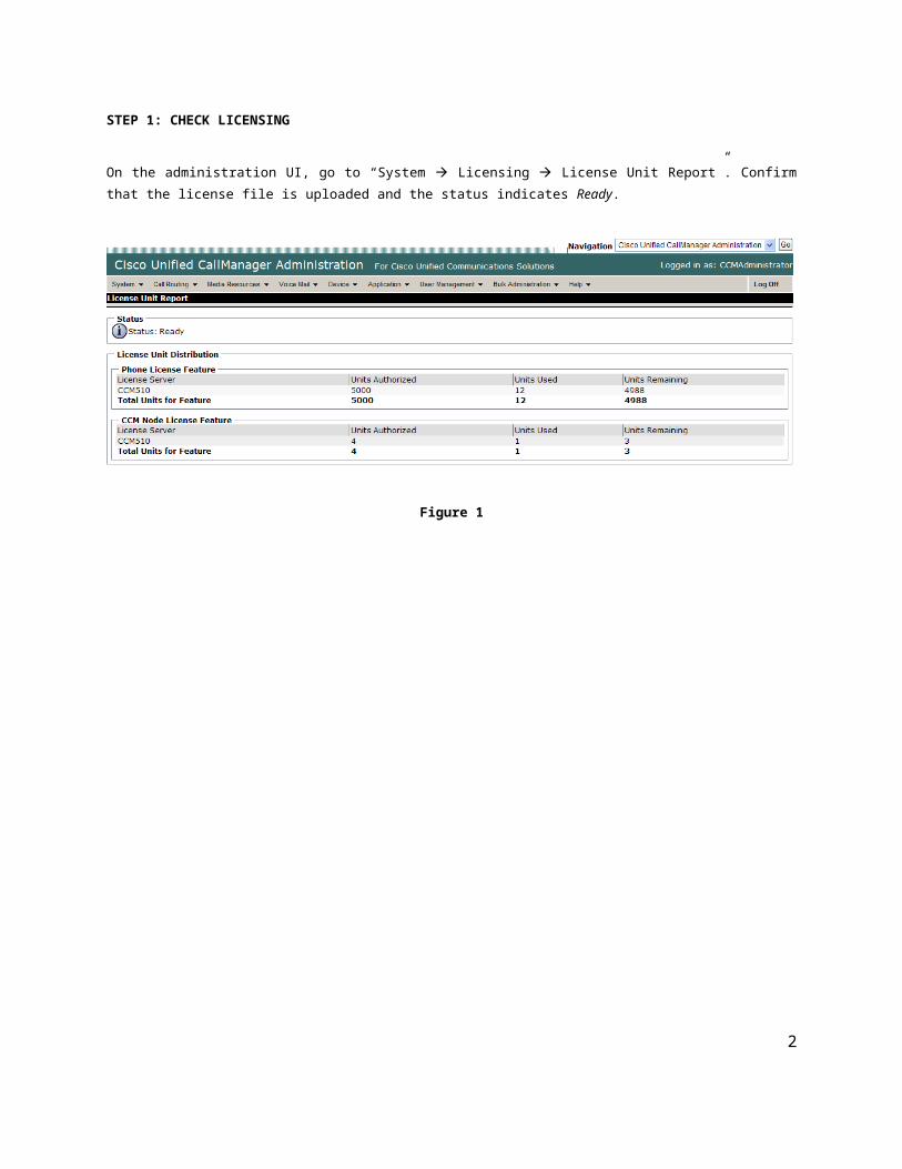
Configure the following parameters for the SIP trunk (Figure 7): Device Pool = Default Media Resource Group List = None Media Termination Point = Checked. When this field is unchecked, the CCM sends SIP INVITEs
to the UM server with no SDP in the offer. When checked, the SIP INVITEs contain SDP in the offer. The UM server supports both, Checked is required if there are Cisco SCCP phones connected to the PBX.
Figure 7
7
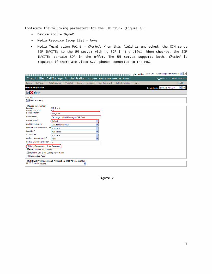
Continue: Configure the following parameters for the SIP trunk (Figure 8): Redirecting Diversion Header Delivery – Inbound = Checked Calling Party Selection = Originator Redirecting Diversion Header Delivery – Outbound = Checked Destination Address = IP Address of the UM Server Destination Port = 5060 when TLS is not used, or 5061 when TLS is used. Preferred Originating Codec = 711uLaw (default) SIP Profile = Standard SIP Profile (default) DTMF Signaling Method: No Preference (default). Using RFC2833 for this field should also work.
Figure 8
8

The standard SIP Profile is shown in Figure 9 and 10:
Figure 9
9

Figure 10
10

STEP 4: CREATE A NEW ROUTE PATTERN
Go to “Call Routing route/hunt route pattern Add New” to create a new route pattern for the Exchange UM pilot number. Configure the following parameters (Figure 11 and 12):
Route Pattern = Pilot number for Exchange UM. Gateway or Route List = Select. Route Option = Route this pattern. Calling Line ID Presentation = Allowed.
Figure 11
11

Figure 12
12

STEP 5: CONFIGURE VOICEMAIL PROFILE
Go to “Voice Mail Voice Mail Pilot Add New” to create a new Voice Mail Pilot. The Voice Mail Pilot Number must correspond to the pilot number configured on the Exchange UM server (Figure 13).
Figure 13
13

Go to “Voice Mail Voice Mail Profile”. Configure the Voice Mail Pilot field under the Default Voice Mail profile to be the Voice Mail Pilot configured earlier (Figure 14 and 15).
Figure 14
Figure 15
14

STEP 6: CHECK THE PHONE CONFIGURATION
Go to “Device Phone” and select the phone you want to configure (Figure 16).
Figure 16
15

Select the line you want to configure its voice mail settings (Figure 17).
Figure 17
16

Confirm the “Voice Mail Profile” is set to the profile configured in Step 5, which contains the pilot number of Exchange UM (Figure 18).
Figure 18
17

Ensure the following are enabled (Figure 19): Forward Busy Internal Forward Busy External Forward No Answer Internal Forward No Answer External
Figure 19
Figure 20
18

OPTIONAL: CONFIGURING MRG & MRGLDepending on actual deployment, you may observe that Exchange UM drops every call from Cisco CallManager. In addition, you may find Event ID 1079 in the system event log of the UM server with the following description:
“The VoIP platform encountered an exception Microsoft.SpeechServer.SpeechApplicationException: The requested DTMF payload type (101) has been refused by the remote end. ---> System.ArgumentException: The requested DTMF payload type (101) has been refused by the remote end……”
First, you need to make sure that the Default MTP Telephony Event Payload Type property under your SIP Profile Configuration has been correctly set to 101 (Figure 9).
If the problem continues to persist, you may be required to use the following configuration on the CallManager:
- Create a Media Termination Point (MTP).- Create a Media Resource Group (MRG) and add the above MTP to this MRG.- Create a Media Resource Group List (MRGL) and add the MRG to this MRGL.- Go to your existing Device Pool configuration page and update the Media Resource Group
List entry to reflect the new MRGL you have created.- Go to your existing SIP Trunk configuration page and update the Media Resource Group
List entry to reflect the new MRGL you have created.
19

1.1. TLS Setup NIL.
1.2. Fail Over Configuration Did not perform fail-over setup.
1.3. Tested Phones Cisco IP Phones SIP – G.711 A Law. Cisco IP Phones Skinny - G.711 A Law.
1.4. Other Comments Please note that the configuration provided in this document does not include the
configuration for Media Resource Groups (MRGs) and Media Resource Group Lists (MRGLs) in the CCM admin, which may be required if the PBX deployment involves the use of .
20
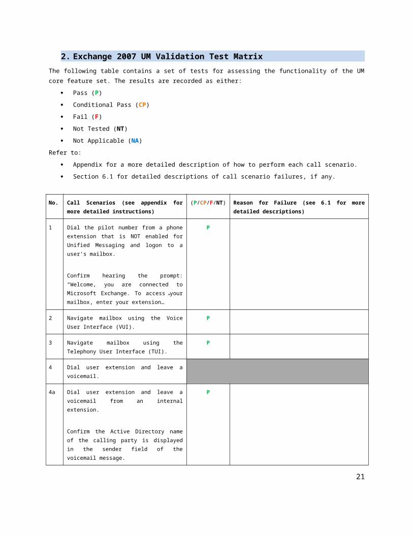
2. Exchange 2007 UM Validation Test MatrixThe following table contains a set of tests for assessing the functionality of the UM core feature set. The results are recorded as either:
Pass (P) Conditional Pass (CP) Fail (F) Not Tested (NT) Not Applicable (NA)
Refer to: Appendix for a more detailed description of how to perform each call scenario. Section 6.1 for detailed descriptions of call scenario failures, if any.
No. Call Scenarios (see appendix for more detailed instructions)
(P/CP/F/NT) Reason for Failure (see 6.1 for more detailed descriptions)
1 Dial the pilot number from a phone extension that is NOT enabled for Unified Messaging and logon to a user’s mailbox.
Confirm hearing the prompt: “Welcome, you are connected to Microsoft Exchange. To access your mailbox, enter your extension…”
P
2 Navigate mailbox using the Voice User Interface (VUI).
P
3 Navigate mailbox using the Telephony User Interface (TUI).
P
4 Dial user extension and leave a voicemail.
4a Dial user extension and leave a voicemail from an internal extension.
Confirm the Active Directory name of the calling party is displayed in the sender field of the voicemail message.
P
4b Dial user extension and leave a voicemail from an external phone.
Confirm the correct phone number of the calling party is displayed in the sender field of the voicemail message.
P
5 Dial Auto Attendant (AA). P
21

Dial the extension for the AA and confirm the AA answers the call.
6 Call Transfer by Directory Search.
6a Call Transfer by Directory Search and have the called party answer.
Confirm the correct called party answers the phone.
P
6b Call Transfer by Directory Search when the called party’s phone is busy.
Confirm the call is routed to the called party’s voicemail.
P
6c Call Transfer by Directory Search when the called party does not answer.
Confirm the call is routed to the called party’s voicemail.
P
6d Setup an invalid extension number for a particular user. Call Transfer by Directory Search to this user.
Confirm the number is reported as invalid.
P
7 Outlook Web Access (OWA) Play-On-Phone Feature.
7a Listen to voicemail using OWA’s Play-On-Phone feature to a user’s extension.
P
7b Listen to voicemail using OWA’s Play-On-Phone feature to an external number.
P
8 Configure a button on the phone of a UM-enabled user to forward the user to the pilot number. Press the voicemail button.
Confirm you are sent to the prompt: “Welcome, you are connected to Microsoft Exchange. <User>. Please enter your pin and press the pound key.”
P
9 Send a test FAX message to user extension.
Confirm the FAX is received in the user’s inbox.
CP CCM 5.1 supports T.38 FAX. However, there are two implementation issues which are causing interop to fail currently. See Section 6.1 for more details.
22

10 Setup TLS between gateway/IP-PBX and Exchange UM.
Replace this italicized text with your TLS configuration: self-signed certificates or Windows Certificate Authority (CA).
10a Dial the pilot number and logon to a user’s mailbox.
Confirm UM answers the call and confirm UM responds to DTMF input.
F Both Exchange UM and CCM5.1 support TLS. However, there are some differences in the protocol implementation which caused the interop to fail. Refer to section 6.1 for more details.
10b Dial a user extension and leave a voicemail.
Confirm the user receives the voicemail.
F
10c Send a test FAX message to user extension.
Confirm the FAX is received in the user’s inbox.
F
11 Setup G.723.1 on the gateway. (If already using G.723.1, setup G.711 A Law or G.711 Mu Law for this step).
Dial the pilot number and confirm the UM system answers the call.
NT G.723.1 is not supported on the Cisco phones used during testing. Refer to section 8.1 for more details.
12 Setup Message Waiting Indicator (MWI).
Geomant offers a third party solution: MWI 2007. Installation files and product documentation can be found on Geomant’s MWI 2007 website.
P
13 Execute Test-UMConnectivity. NT
14 Setup and test fail-over configuration on the IP-PBX to work with two UM servers.
NT
23

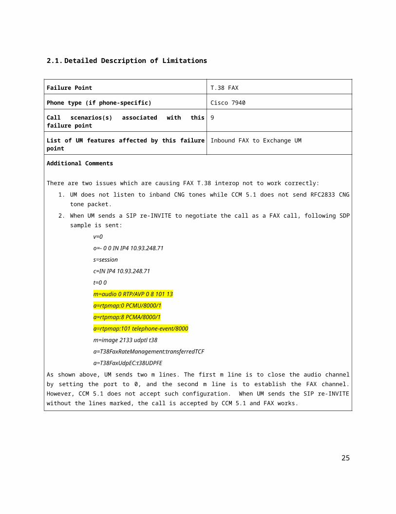
2.1. Detailed Description of Limitations
Failure Point T.38 FAX
Phone type (if phone-specific) Cisco 7940
Call scenarios(s) associated with this failure point
9
List of UM features affected by this failure point
Inbound FAX to Exchange UM
Additional Comments
There are two issues which are causing FAX T.38 interop not to work correctly:1. UM does not listen to inband CNG tones while CCM 5.1 does not send RFC2833 CNG tone
packet.2. When UM sends a SIP re-INVITE to negotiate the call as a FAX call, following SDP sample is
sent:v=0o=- 0 0 IN IP4 10.93.248.71s=sessionc=IN IP4 10.93.248.71t=0 0m=audio 0 RTP/AVP 0 8 101 13a=rtpmap:0 PCMU/8000/1a=rtpmap:8 PCMA/8000/1a=rtpmap:101 telephone-event/8000m=image 2133 udptl t38a=T38FaxRateManagement:transferredTCFa=T38FaxUdpEC:t38UDPFE
As shown above, UM sends two m lines. The first m line is to close the audio channel by setting the port to 0, and the second m line is to establish the FAX channel. However, CCM 5.1 does not accept such configuration. When UM sends the SIP re-INVITE without the lines marked, the call is accepted by CCM 5.1 and FAX works.
24
Failure Point TLS
Phone type (if phone-specific) -
Call scenarios(s) associated with this failure point
10
List of UM features affected by this failure point
Exchange UM operating in SIPSecured mode
Additional Comments
CCM 5.1 and Exchange UM support TLS over SIP trunk. However, there are some differences in the protocol implementation, including a mismatch of cipher suites supported, which are causing interop to fail. We are working to resolve these differences.
Failure Point G.723.1
Phone type (if phone-specific) G7490
Call scenarios(s) associated with this failure point
11
List of UM features affected by this failure point
G.723.1 Encoding
Additional Comments
CCM 5.1 supports G.723.1 codec in the SIP trunk. However, the CISCO phones available during testing do not support G.723.1. While hardware-based transcoders can be used to perform the necessary transcoding between G.723.1 and the codec(s) supported by the phones, none were unavailable at the time of testing.
3. Troubleshooting
No troubleshooting information available.
25

Appendix
1. Dial Pilot Number and Mailbox Login Dial the pilot number of the UM server from an extension that is NOT enabled for UM. Confirm hearing the greeting prompt: “Welcome, you are connected to Microsoft Exchange. To
access your mailbox, enter your extension...” Enter the extension, followed by the mailbox PIN of an UM-enabled user. Confirm successful logon to the user’s mailbox.
2. Navigate Mailbox using Voice User Interface (VUI) Logon to a user’s UM mailbox. If the user preference has been set to DTMF tones, activate the Voice User Interface (VUI)
under personal options. Navigate through the mailbox and try out various voice commands to confirm that the VUI is
working properly. This test confirms that the RTP is flowing in both directions and speech recognition is working
properly.
3. Navigate Mailbox using Telephony User Interface (TUI) Logon to a user’s UM mailbox. If the user preference has been set to voice, press “#0” to activate the Telephony User
Interface (TUI). Navigate through the mailbox and try out the various key commands to confirm that the TUI is
working properly. This test confirms that both the voice RTP and DTMF RTP (RFC 2833) are flowing in both
directions.
4. Dial User Extension and Leave Voicemail Note: If you are having difficulty reaching the user’s UM voicemail, verify that the coverage
path for the UM-enabled user’s phone is set to the pilot number of the UM server.
5. From an Internal Extension From an internal extension, dial the extension for a UM-enabled user and leave a voicemail
message. Confirm the voicemail message arrives in the called user’s inbox. Confirm this message displays a valid Active Directory name as the sender of this
voicemail.
26

f. From an External Phone From an external phone, dial the extension for a UM-enabled user and leave a voicemail
message. Confirm the voicemail message arrives in the called user’s inbox. Confirm this message displays the phone number as the sender of this voicemail.
7. Dial Auto Attendant(AA) Create an Auto Attendant using the Exchange Management Console:
Under the Exchange Management Console, expand “Organizational Configuration” and then click on “Unified Messaging”.
Go to the Auto Attendant tab under the results pane. Click on the “New Auto Attendant…” under the action pane to invoke the AA wizard. Associate the AA with the appropriate dial plan and assign an extension for the AA. Create PBX dialing rules to always forward calls for the AA extension to the UM server. Confirm the AA extension is displayed in the diversion information of the SIP Invite.
Dial the extension of Auto Attendant. Confirm the AA answers the call.
8. Call Transfer by Directory Search Method one: Pilot Number Access
Dial the pilot number for the UM server from a phone that is NOT enabled for UM. To search for a user by name: Press # to be transferred to name Directory Search.
Call Transfer by Directory Search by entering the name of a user in the same Dial Plan using the telephone keypad, last name first.
To search for a user by email alias: Press “#” to be transferred to name Directory Search Press “# #” to be transferred to email alias Directory Search Call Transfer by Directory Search by entering the email alias of a user in the
same Dial Plan using the telephone keypad, last name first. Method two: Auto Attendant
Follow the instructions in appendix section 5 to setup the AA. Call Transfer by Directory Search by speaking the name of a user in the same Dial
Plan. If the AA is not speech enabled, type in the name using the telephone keypad. Note: Even though some keys are associated with three or four numbers, for each letter, each
key only needs to be pressed once regardless of the letter you want. Ignore spaces and symbols when spelling the name or email alias.
27

9. Called Party Answers Call Transfer by Directory Search to a user in the same dial plan and have the called party
answer. Confirm the call is transferred successfully.
10. Called Party is Busy Call Transfer by Directory Search to a user in the same dial plan when the called party is busy. Confirm the calling user is routed to the correct voicemail.
11. Called Party does not Answer Call Transfer by Directory Search to a user in the same dial plan and have the called party not
answer the call. Confirm the calling user is routed to the correct voicemail.
12. The Extension is Invalid Assign an invalid extension to a user in the same dial plan. An invalid extension has the same
number of digits as the user’s dial plan and has not been mapped on the PBX to any user or device.
UM Enable a user by invoking the “Enable-UMMailbox” wizard. Assign an unused extension to the user. Do not map the extension on the PBX to any user or device. Call Transfer by Directory Search to this user. Confirm the call fails and the caller is prompted with appropriate messages.
13.Play-On-Phone To access play-on-phone:
Logon to Outlook Web Access (OWA) by going to URL https://<server name>/owa. After receiving a voicemail in the OWA inbox, open this voicemail message. At the top of this message, look for the Play-On-Phone field ( Play on Phone...). Click this field to access the Play-On-Phone feature.
n. To an Internal Extension Dial the extension for a UM-enabled user and leave a voicemail message. Logon to this called user’s mailbox in OWA. Once it is received in the user’s inbox, use OWA’s Play-On-Phone to dial an internal extension. Confirm the voicemail is delivered to the correct internal extension.
28

15. To an External Phone number Dial the extension for a UM-enabled user and leave a voicemail message. Logon to the UM-enabled user’s mailbox in OWA. Confirm the voicemail is received in the user’s mailbox. Use OWA’s Play-On-Phone to dial an external phone number. Confirm the voicemail is delivered to the correct external phone number. Troubleshooting:
Make sure the appropriate UMMailboxPolicy dialing rule is configured to make this call. As an example, open an Exchange Management Shell and type in the following commands:
$dp = get-umdialplan -id <dial plan ID> $dp.ConfiguredInCountryOrRegionGroups.Clear() $dp.ConfiguredInCountryOrRegionGroups.Add("anywhere,*,*,") $dp.AllowedInCountryOrRegionGroups.Clear() $dp.AllowedInCountryOrRegionGroups.Add(“anywhere") $dp|set-umdialplan $mp = get-ummailboxpolicy -id <mailbox policy ID> $mp.AllowedInCountryGroups.Clear() $mp.AllowedInCountryGroups.Add("anywhere") $mp|set-ummailboxpolicy The user must be enabled for external dialing on the PBX. Depending on how the PBX is configured, you may need to prepend the trunk access
code (e.g. 9) to the external phone number.
16.Voicemail Button Configure a button on the phone of a UM-enabled user to route the user to the pilot number of
the UM server. Press this voicemail button on the phone of an UM-enabled user. Confirm you are sent to the prompt: “Welcome, you are connected to Microsoft Exchange.
<User Name>. Please enter your pin and press the pound key.” Note: If you are not hearing this prompt, verify that the button configured on the phone passes
the user’s extension as the redirect number. This means that the user extension should appear in the diversion information of the SIP invite.
17.FAX Use the Management Console or the Management Shell to FAX-enable a user. Management Console:
29

Double click on a user’s mailbox and go to Mailbox Features tab. Click Unified Messaging and then click the properties button. Check the box “Allow faxes to be received”.
Management Shell - execute the following command: Set-UMMailbox –identity UMUser –FaxEnabled:$true
To test fax functionality: Dial the extension for this fax-enabled UM user from a fax machine. Confirm the fax message is received in the user’s inbox. Note: You may notice that the UM server answers the call as though it is a voice call
(i.e. you will hear: “Please leave a message for…”). When the UM server detects the fax CNG tones, it switches into fax receiving mode, and the voice prompts terminate.
Note: UM only support T.38 for sending fax.
18.TRANSPORT SECURITY LAYER (TLS) Setup TLS on the gateway/IP-PBX and Exchange 2007 UM. Import/Export all the appropriate certificates.
19. Dial Pilot Number and Mailbox Login Execute the steps in scenario 1 (above) with TLS turned on.
20. Dial User Extension and Leave a Voicemail Execute the steps in scenario 4 (above) with TLS turned on.
21. FAX Execute the steps in scenario 9 (above) with TLS turned on.
22.G.723.1 Configure the gateway to use the G.723.1 codec for sending audio to the UM server. If already using G.723.1 for the previous set of tests, use this step to test G.711 A Law or
G.711 Mu Law instead. Call the pilot number and verify the UM server answers the call. Note: If the gateway is configured to use multiple codecs, the UM server, by default, will use
the G.723.1 codec if it is available.
23.Message Waiting Indicator (MWI) Although Exchange 2007 UM does not natively support MWI, Geomant has created a 3rd party
solution - MWI2007. This product also supports SMS message notification. Installation files and product documentation can be found on Geomant’s MWI 2007 website.
30

24.Test-UMConnectivity Run the Test-UMConnectivity diagnostic cmdlet by executing the following command in
Exchange Management Shell: Test-UMConnectivity –UMIPGateway:<Gateway> -Phone:<Phone> |fl <Gateway> is the name (or IP address) of the gateway which is connected to UM, and through
which you want to check the connectivity to the UM server. Make sure the gateway is configured to route calls to UM.
<Phone> is a valid UM extension. First, try using the UM pilot number for the hunt-group linked to the gateway. Next, try using a CFNA number configured for the gateway. Please ensure that a user or an AA is present on the UM server with that number.
The output shows the latency and reports if it was successful or there were any errors.
25.Test Fail-Over Configuration on IP-PBX with Two UM Servers This is only required for direct SIP integration with IP-PBX. If the IP-PBX supports fail-over
configuration (e.g., round-robin calls between two or more UM servers): Provide the configuration steps in Section 5. Configure the IP-PBX to work with two UM servers. Simulate a failure in one UM server. Confirm the IP-PBX transfers new calls to the other UM server successfully.
31