Digital Data Communications - Branding - Overview - Strategies - Vision & Mission
Upload
phunghuongCategory
view
212download
0
AAS 04-114
CALIPSO’S MISSION DESIGN: SUN-GLINT AVOIDANCE STRATEGIES
Laurie M. Mailhe Conrad SchifT
John €I. Stadler
CALIPSO will fly in formation with the Aqua spacecraft to obtain a coincident image of a portion of the Aqua/MODIS swath. Since MODIS pixels suffering sun-glint degradation are not processed, it is essential that CALIPSO only co- image the glint h e portion of the MODIS instrument swath. This paper presents sun-glint avoidance strategies for the CALIPSO mission First, we introduce the Aqua sun-glint geometxy and its relation to the CALIPSO-Aqua formation flying parameters. Then, we detail our implementation of the computation and perform a cross-track trade-space analysis. Finally, we analyze the impact of the sun-ght avoidance strategy on the spacecraft power and delta- V budget over the mission lifetime.
INTRODUCTION
The Cloud-Aerosol Lidar and Infrared Pathfinder Satellite Observations (CALIPSO) mission is jointly developed under partnership by NASA Langley Research Center (LaRC), the French Centre National D’Etudes Spatiales (CNES), Hampton University 0, the Institute Pierre Simon Laplace (IPSL), and Ball Aerospace. The goal of the CALPSO mission is to provide measurements of aerosols, cloud vertical structure and cloud optical properties. CALIPSO is a member of the Afternoon Constellation along with the Aqua, Cloudsat, Parasol and Aura satellites.’” To meet its science objective, the CALPSO spacecraft will fly in formation with the Aqua spacecrafi in a fiozen, Sun-synchronous orbit with a 705-kilometer altitude at the equator crossing. The CALPSO mission, currently planned to be launched in March 2005, is divided in two phases with a total mission lifetime of 3 yearsu During the first two years of the mission, referred to as Phase 1, CALIPSO will closely follow Aqua so that its CALIOP (Cloud- Aerosol LIdar with Orthogonal Polarization) instrument takes measurement of a small portion of the Aqua MODIS (MODerate resolution Imaging Spectro-radiometer) instrument’s imaging swath at the ascending node crossing. During the last year of the CALPSO mission, referred to as Phase 2, CALIPSO’s orbit will precess to enable the CALIOP instrument to sample the western section of Aqua’s MODIS instrument swath.
Mission Analyst at a.i solutions, Inc. lo001 Derekwood Lane, Suite 215, bnham, MD, 20706. E-mail: [email protected]. Phone: (301) 306-1756 ext. 126, Fax: (301) 306-1754. Web Site: http://www.ai-solutions.com.
Chief Scientist at a i . solutions, Inc. lo001 Derekwood Lane, Suite 215, Lanham, MD, 20706. E-mail: [email protected]. Phone: (301) 306-1756 at . 118, Fax: (301) 306-1754. Web Site: http://www.ai-solutiom.com
CALIF’S0 Mission System Engineer at NASA Langley Research Center, 100 NASA Road Hampton, VA 23681-2199. E-mail [email protected]. Phone: (757) 864-7076, Fax: (757) 864-7775. Web Site: http://www.larc.nasa.gov.
1
https://ntrs.nasa.gov/search.jsp?R=20040081137 2018-06-17T13:02:54+00:00Z

NASA's Terra mission, launched in 1999, is flykg a MODIS instrument performing measurements identical to the Aqua's. Scientists discovered that Terra MODIS image data are degraded by sun-glint, since the MODIS is unable to distinguish sun-glint from highly reflective clouds. Based on the results of the Terra MODIS instrument data, the Aqua imaging strategy was modified so that its MODIS does not process data that are within a predefined sun-glint region. This change in imaging strategy led the CALIPSO science team to reconsider their formation flying strategy with Aqua during Phase 1?$ The on@ CALIPSO strategy was to fly in formation with Aqua such that CALJOP observed the that portion of the MODIS swath covering Aqua's subsatellite point (Le. the point on the Earth directly along Aqua's nadir direction) within 2 minutes of Aqua's measurements. Because the data loss due to the sub- satellite point passage through the sun-glmt region was judged to be unacceptable, a change in the way CALIPSO flies in formation with Aqua during Phase 1 was considered. If CALIPSO could fly behind Aqua with an eastern cross-track shift with respect to Aqua's sub-satellite poht, then CALIPSO could perform its coincident imaging with a portion of the MODIS swath that is affkcted less by sun-glint (see Figure 1 for the relevant geometry). Its time separation strategy with Aqua would remain identical to the ori@ plan to eliminate any close approach issues and to ensure that the coincident imaging conditions are met.
This paper is divided into four sections. The first section presents the Aqua MODIS sun-glmt geometry and its relationship to the CALIPSO-Aqua formation flying geometry. The second section details the implementation of the sun-glmt computation for Phase 1 of the CALIPSO mission. Ths Athid sectin discuses thc i e d t s from &c cmss-tick tide-qace analysis 2s well as the impact of the cross-track error budget on CALIPSO's imaging strategy. Finally, the fourth section focuses on the impact of the sun-glint avoidance strategy on the spacecraft power and delta-V budget over the mission lifetime.
THE SUN-GLINT AND FORMATION FLYING GEOMETRIES
In this section, a definition of sun-glint and a brief description of the corresponding Sun-Earth- CALIPSO orbit geometry are provided. Then, a more detailed derivation of the Aqua MODIS-specific sun-glint geometry with its appropriate h e and variables are given. Finally, the main formation-flying design parameters are presented in relation to the sun-glint geometry.
Sun-glint Definition
Sun-glmt is created by the reflectance of high-intensity solar rays from the Earth's surface. The closer the reflected rays are to the specular direction, the higher is their intensity. High-intensity reflected rays can prevent the MODIS instrument fiom performing proper science measurements; this phenomenon was observed on the Terra mission. Based on the Terra findings, Aqua does not process any data suffering from sun-glint, defined to be data collected within 40" of the specular direction. Because of power considerations, the CALPSO team chose to mitigate data loss originating within a 35" cone about the specular direction.
Figure 1 shows a schematic of the Aqua sun-glint region, shown on a 2-D projection in the Earth's body-fixed fi-ame, looking down the nadir with respect to the MODIS swath for October 0 1,200 1. Because the sun-glint region is determined by the Sun-Earth-Aqua orbit geometry, its position with respect to the MODIS swath will vary with the seasons. The relative Sun path, as seen on the 2-D projection on the Earth's, is called the analema9 and is shown in Figure 2. The Sun traces a figure-eight ground track on the Earth, where the highest latitude point represents
2

the summer solstice and the lowest latitude the winter solstice. The equator crossing point represents the spring and fall equinoxes. The sun-glint region moves as the Sun moves along the analema.
Another interesting parameter for this study is the beta angle defined as the complement to the angle between the n o m 1 to the orbit plane and the Sun. In other words, it represents the angle between the orbital plane and the Sun as illustrated in Figure 3. The smaller the beta angle is the closer is the Sun to shining onto the edge of the spacecraft’s orbit plane. The worst sun-glint case will occur at the smallest beta angle. Figure 4 shows Aqua’s beta angle history for one year. From Figure 4, it can be observed that the worst case occurs around summer solstice.
A I I NORTH
Sun glint Region .
-38 deg. ...........
S ....
u 3 5 deg. N
Figure 1. Aqua MODIS Sun-glint Region Schematic for One Revolution (Epoch: October 01,2001).
3

Figure 2. Sun Ana ilema for 1 year (Starting Epoch June 21,2 ;oo4 12 :oo: :oo ,000)
Orbit's Plane i
Normal to the Orbit's
Plane Sun
---------
Figure 3. Schematic of the Beta Angle Definition
4

Aqua Beta Angle One-Year Propagation
30.0
27.5
.- 25.0
20.0
i 7.5
Jan 2004 APr Jul OCt Jan 2005 CALIPSO Epoch
Figwe 4. Aqua’s Beia Angle for One-Year Propagation
Aqua Sun-glint Geometry
To derive quantitative results, a detailed model of the Aqua sun-glint imaging is needed. The Aqua MODIS swath was divided into 33286 pixels, each pixel being 70 meters in size which corresponds to the diameter of the CALIOP swath. The aim is then to determine whether a given pixel (labeled P) of the Aqua’s MODIS instrument is suffering fiom sun-ght or not.
The first vector of interest is the Sun-Earth unit vector in the mean of 52000 Geocentric Inertial (GCI) h e for a specific epoch, labeled t, which is defined as:
A ES
where E and S represent the Earth and the Sun, respectively.
Let us assume that the angle between Aqua’s nadir direction and the vector from Aqua to the MODIS pixel P is known. This angle is referred to as the view angle or MODIS angle ((3”). Figure 5 illustrates a schematic of the MODIS sensor view angle geometry as defined for a given pixel P.
5
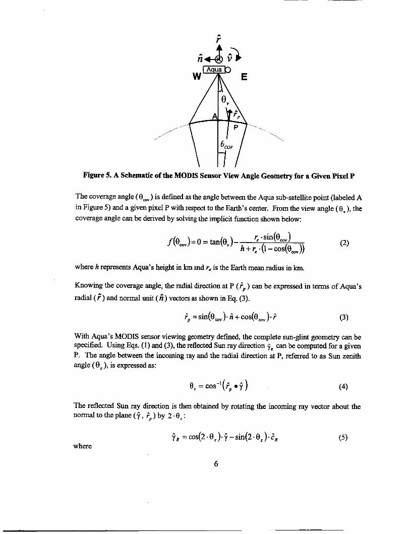
Figure 5. A Schematic of the MODIS Sensor View Angle Geometry for a Given Pixel P
The coverage angle (e,) is defined as the angle between the Aqua sub-satellite point (labeled A in Figure 5) and a given pixel P with respect to the Earth’s center. From the view angle (ev), the coverage angle can be derived by solving the implicit function shown below:
where h represents Aqua’s height in km and re is the Earth mean radius in loa
Knowing the coverage angle, the radial direction at P ( FP ) can be expressed in terms of Aqua’s
radial(~)andnormalunit(~)vectorsasshowninEq. (3).
With Aqua’s MODIS sensor viewing geometry defined, the complete sun-glint geometry can be specified. Using Eqs. (1) and (3)’ the reflected Sun ray direction f R can be computed for a given P. The angle between the incoming ray and the radial direction at P, referred to as Sun zenith angle (8, ), is expressed as:
e, =cos-’(;, .f ) (4)
The reflected Sun ray direction is then obtained by rotating the incoming ray vector about the normal to the plane ( 5 , ?,) by 2 -8; :
6

and
A 1 1 . cR = n R x y
The sun-ght angle (0,) for pixel P is defined as the angle between the reflected ray vector and the direction from the pixel P to Aqua, also refmed to as view vector:
where
If, for a given pixel P, the value of the glint angle goes below the critical value of 35" at any given time during the mission, we will say that the pixel measurement suffers from sun-glint and coincident imaging between CALPSO and Aqua will be deemed impossible.
Formation Flying Geometry
Now that we can assess whether a given Aqua MODIS pixel suffers from sun-glint or not, we can design the CALIPSO formation flying with Aqua in order to avoid coincident CACIOP imaging with the Aqua sun-glint region. The CALIPSO's formation flying strategy requires two parameters to be specified: CALIPSO's equator crossing lag time with respect to Aqua (dfh) and the desired eastern cross-track shifl (sh$dj,,, ) at equator crossing with respect to the Aqua MODIS swath. The lag time will be held constant throughout this analysis at a nominal value of 1.22 minutes. This nominal value is derived from Aqua's and CALIPSO's respective control box sizes. In the initial formation flying strategy, CALIPSO was to fly directly behind Aqua so that CAL,IOP could image the Aqua sub-satellite point (i.e., zero view angle and zero ~h&gli,t)!*~
For the sun-ght avoidance formation flying strategy, CALIPSO's orbit is shifted east with respect to the Aqua spacecraft's orbit; the magnitude of the cross-track shift can be varied to enable coincident imaging with a portion of the MODIS swath not suffering h m sun-glint. Figure 6 summarizes the Aqua sun-ght geometry as defined in this paper in relation to the CALIOP instrument beam.
7

min
MODIS Swath
Figure 6. Schematic of the Sun-glint Geometry The cross-track shift will he varied and the glint mgk and view angle computed for each different cross-track value. Note that the right ascension of the ascending node includes an additional shift to compensate for the rotation of the Earth during dthr Thus, when propagated forward 1.22 minutes, CALIPSO will “see” the same MODIS pixel on the ground as specified by shiftgiint. Based on the two formation flying design parameters, the CALIPSO initial conditions are determined. Then Eqs. (10) and (11) are used as approximations to estimate CALIPSO’s initial true anomaly (TA) and right ascension of the ascending node (Q).
Aqua
where d2m is a day-expressed in minutes (i.e., 1440 minutes) and PAW is Aqua’s period. Note
that Shzpglint is the plane shift due to sun-glint avoidance strategy only.
The sun-glmt angle computation described in this section will be implemented for various CALIPSO formation flying strategies. A more detailed explanation about the control strategy is given in the last section of this paper.
SUN GLINT COMPUTATION IMPLEMENTATION
In the previous section, an expression computing the sun-ght angle for a given view angle (or cross-track shift) was given. While an approximation to the sun-glint angle and desired formation flying parameters can be generated using spherical geometry and two-body motion,’o we choose to implement the above equations in conjunction with high-fidelity models of the
8

formation’s orbital motion in a FreeFlyd/MATLAE3@ simulation. The CALIPSO FreeFIyd script is fully automated and it allows quick and easy runs of the sun-glint angle trade-space analysis to be performed.
For OUT simulation, Aqua’s trajectory was modeled using the latest Aqua mission planning ephemeris. The Aqua spacecraft state was propagated to the desired starting epoch. A graphical user panel prompts the user to enter the desired cross-track shiftglt range, a step value for variation in a for-loop and d t k (set to 1.22 minute for this study) for the trade-space analysis. The formation flying cross-track parameter shiJtglint is varied via a for-loop. Based on Aqua’s state and the formation flying parameters, CALIPSO’s new formation flying initial conditions are determined using the FreeFlyefi targeter with Eqs.(lO) and (11) as initial guesses. The targeter tolerances were set to f O.OOO1 minute and f 0.5 km for the d t h and shzj&*, respectively. The CALIPSO spacecraft force model was set to be identical to the one used to generate Aqua’s ephemeris. For each sh$diM cross-track value, CALPSO and Aqua’s orbits are propagated for one revolution, during which the Sun zenith angle, the MODIS pixel view angle and the sun-glint are computed using MATLAB@. For this simulation, the view angle corresponding to a given cross-track shift is computed using a fictitious spacecraft (labeled CP-View) as shown in Figure 7.
Maintenance Box
MODIS Swath
Figure 7. Schematic of Fictitious Spacecraft (CP-View) Geometry
The fictitious spacecraft’s trajectory is designed such that it flies directly above the Aqua’s MODIS swath, crossing the equator at the same time as Aqua @.e., zero lag time). Its ground- track is identical to the actual CALIPSO ground-track (labeled CP). The view angle computations are directly derived from CP-View as shown in the equations below:
9

where F is Aqua's position vector and Fp is CALIPSO's position vector when co-imaging a portion of the MODIS swath @e., CP-View position vector).
TRADESPACE ANALYSIS RESULTS
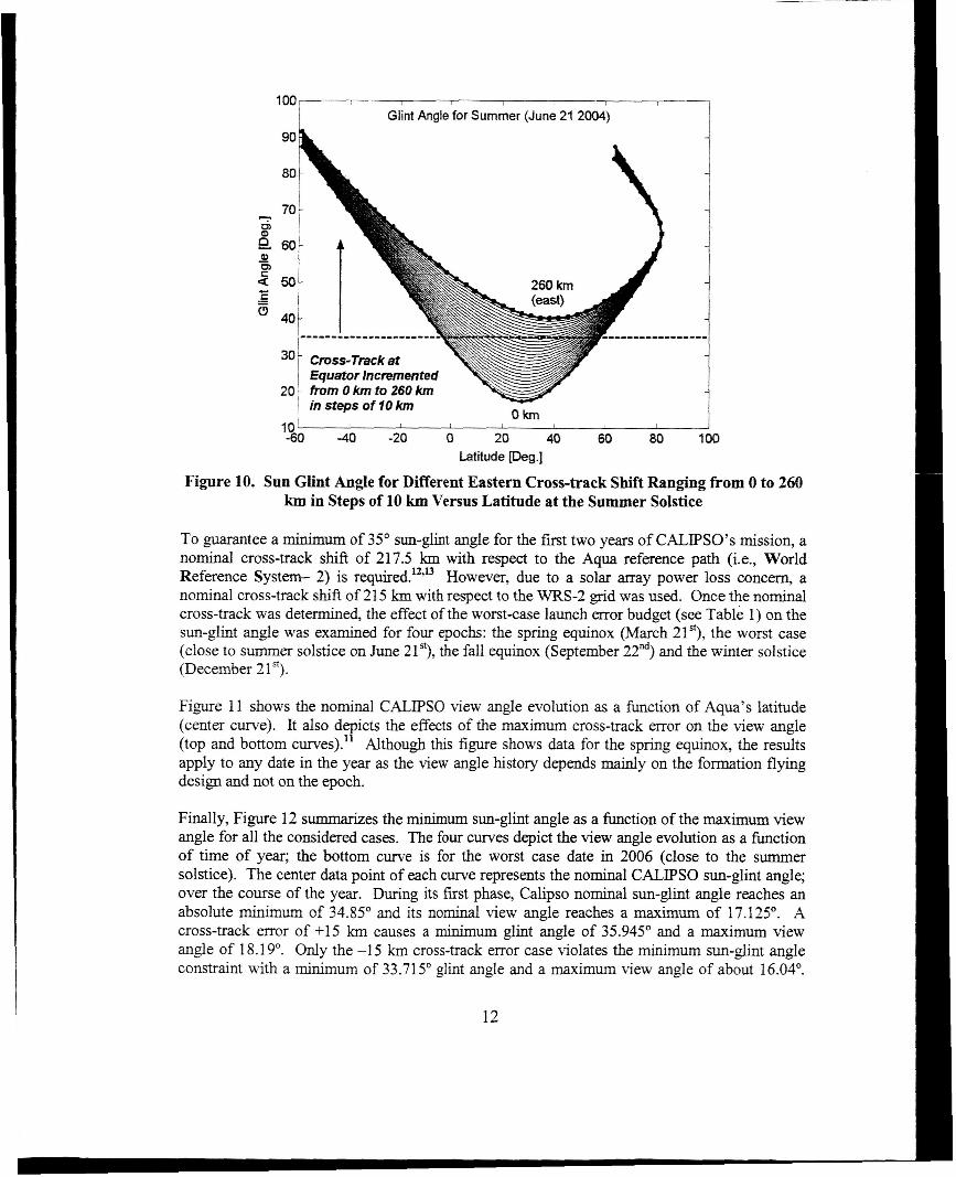
In the previous section, we presented our implementation of the sun-glint angle for a given cross-track (or view angle). In this section, we run a trade-space analysis with cross-track shift values with respect to Aqua equator crossing varied fiom 0 to 260 km in steps of 10 km. If at a given epoch, a chosen pixel (characterized here by its maximum view angle) does not suffer fiom sun-ght then it is also true for all epochs with beta angle greater than the considered epoch. Following that logic, the cross-track separation value should be based on the summer solstice epoch as it is dose io the mlrriinilm beii angle value. For each cress-track shift value, we computed the corresponding view angle and g h t angle. Once we found the minimum cross- track shift which ensures co-imaging with a g h t free portion of the Aqua MODIS, we refined OUT solution to within 1 km accuracy." Note that a 10 km east cross-track shift at the E!quator crossing translates into a change in right ascension of ascending node of 0.089849". Figure 8 shows the Sun zenith angle evolution for one orbit at Aqua's sub-satellite point for the sum me^
solstice (i.e., the worst sun-glint case). When the Sun zenith angle is greater than 90"' Aqua has crossed to the 'night-side' of the Earth where the measurements are not affected by sun-ght and can be neglected from this study. All subsequent plots do not include the 'night-side' portion of Aqua's ground-track Figure 9 represents the view angle evolution as a function of latitude. As expected, the maximum view angle is reached around the Equator crossing. For the chosen shzFgh coarse range, the maximum view angle ranges from 0" to 22" in steps of about 0.8O. Figure 10 shows the sun-glint angle history as a function of latitude. The 35" threshold is indicated by a thick horizontal line to highhght which cross-track cases were suffering fiom sun-
. .
ght.
10

Zenith Angle for Summer ( June 21 2004)
l m m
Q 0) - ; -10-
5 -15
-20
0' I I I I I I I I
-80 -60 -40 -20 0 20 40 60 80 Latitude [Des.]
Figure 8. Sun Zenith Angle for Aqua's Sub-satellite Pixel versus Latitude at the Summer Solstice
-
-
10 I I
V i Angle for Summer (June 21 2004) 1 1
instepsoflOkm 260 km (east)
-1 00 -50 0 50 100 Latitude [Des.]
-25 I I I
Figure 9. MODIS Pixel View Angle for Different Eastern Cross-track Shift Ranging from 0 to 260 km in Steps of 10 km versus Latitude
1 1
100 , I I 8
Glint Angle for Summer (June 21 2004)
------------------
in steps of I O km
.- -60 -40 -20 0 20 40 60 80 loo
Latitude b.] Figure 10. Sun Glint Angle for Different Eastern Cross-track Shift Ranging from 0 to 260
km in Steps of 10 km Versus Latitude at the Summer Solstice
To guarantee a minimum of 35" sun-ght angle for the first two years of CALIpSO's mission, a nominal cross-track shift of 217.5 km with respect to the Aqua reference path (i.e., World Reference System- 2) is required.u313 However, due to a solar array power loss concern, a nominal cross-track shift of 215 km with respect to the WRS-2 grid was used. Once the nominal cross-track was determined, the effect of the worstcase launch mor budget (see Table 1) on the sun-glint angle was examined for four epochs: the spring equinox (March 21'), the worst case (close to summer solstice on June 21'), the fall equinox (September 22"d) and the winter solstice (December 2lS).
Figure 11 shows the nominal CALIF'S0 view angle evolution as a h c t i o n of Aqua's latitude (center curve). It also depicts the effects of the maximum cross-track mor on the view angle (top and bottom curves)." Although this figure shows data for the spring equinox, the results apply to any date in the year as the view angle history depends mainly on the formation flying design and not on the epoch.
Finally, Figure 12 summarizes the minimum sun-glint angle as a function of the maximum view angle for all the considered cases. The four curves depict the view angle evolution as a function of time of year; the bottom curve is for the worst case date in 2006 (close to the summer solstice). The center data point of each curve represents the nominal CALIPSO sun-glmt angle; over the course of the year. During its first phase, Calipso nominal sun-glint angle reaches an absolute minimum of 34.85" and its nominal view angle reaches a maximum of 17.125'. A cross-track error of +15 km causes a minimum glint angle of 35.945" and a maximum view angle of 18.19'. Only the -15 km cross-track error case violates the minimum sun-glmt angle constraint with a minimum of 33.715' glint angle and a maximum view angle of about 16.04'.
12

However, the CALIPSO initial conditions could be determined by positioning it on the eastern side of its maintenance window during the worst summer year.
Table 1
CALIPSO CROSS-TRACK ERROR BUDGET RELATIVE TO AQUA"
Error Source Error tkml Comments
Launch Errors Total (RSS) k3.3 Includes a Q.2 km for the line-of-nodes error (k0.02") and e . 5 km for the launch window error window error
Margin k2.0 51 5.3
Figure 11
Epoch: March 20,2006.
-1 00 30 0 100 Latiiude [Des.]
Equinox . Calipso View Angle (Absolute Value) as a function of Latitude at the Spring
13

48
....................... .! ................... ...i. ....... . i.. ........... i ................................
-o- Worst Day (le., - Summer Solstice) -C Winter Solstice + Fall Equinox
I
........... i .............................. ........................
4 +15 k
34
16 16.5 17 17.5 18 18.5 Max. view Angle peg.]
Figure 12 Minimum Glint Angle vs. Maximum View Angle for the Nominal CALIPSO Orbit with Added Cross-track Error
NOMINAL SUN GLINT AVOIDANCE FORMATION FLYING LIFETIME ANALYSIS
In the previous section, we determined the nominal cross-track shift with respect to Aqua so that CALIPSO does not perform coincident imaging with any portion of the MODIS swath suffering fiom sun-glint. In this section, we compare the new formation flying strategy to the 0rigjna.l formation flying strategy where CALlPSO flew the same ground track as Aqua.15 The comparison was made for two specific parameters: beta angle and overall delta-V budget. The beta angle must be closely monitored to ensure CALIPSO power margins are maintained. Another parameter considered was the overall delta-V budget. For the new formation flying strategy, CALIPSO is shifted 215 km east of Aqua sub-satellite point. Phase 2 of the mission requires the spacecraft to precess through the entire western edge of the MODIS swath. As a result, the delta-V budget must increase in order to accommodate a larger inclination maneuver as compared to the initial strategy. Note that the separation time at equator crossing remains unchanged between the two strategies at a nominal value of 1.22 minutes (center-tocenter of Aqua and CALIPSO ground-track control boxes). This value assumes that both Aqua and CALIPSO maintain a i10 km control box. For the sun-glint avoidance formation flying strategy, the spacecraft will be maintained to a WRS-2 grid shifted 215 km east during Phase 1. During Phase 2, both formation flying strategies will maintain a control box with respect to a WRS-2 drifting with the spacecraft plane.
CALIPSO is required to follow Aqua by up to 2 minutes and 45 seconds for coincident imaging to occur. For the CALIPSO and Aqua formation, only CALIPSO is required to perform maneuvers to control the formation. Aqua simply maintains its own mission requirements, maneuvering as needed. Table 2 Summarizes the initial formation flying (Formation 1) and the
14

new sun-glmt avoidance formation flying (Formation 2) requirements for each phase of the mission.
Table 2
FORMATION FLYING REQUIREMENTS FOR FORMATION 1 AND FORMATION 2
Nominal Cross-Track Separation Phase Control Box Grid Control Separation with respect to Aaua at Duration Reference - Box
Time at Eauator Crossing - Sue
1 Formation 1.22 rnin + 215 km 2 years WRS-2 Grid + 215 2 10 km
Formation 1.22 rnin drift from 0 km to - 1165 1 year nla 2 10 km 1 km Formation 1.22 min drift from +215 to -1 165 1 year nla f 10 km 2 km
km shift
This nominal separation time assumes that both CALIPSO and Aqua maintain a +/- 70 km control box. 1
Figere 13 2!1strztes CALIPCO’s !eczttim relative te &e swah of ?he Aqua MODIS instrument for both the Formation 1 and Formation 2 scenarios. For Formation 2, CALPSO remains at 215 km east of the MODIS swath during Phase 1 and it will sweep fiom 215 km east of Aqua sub-satellite through the entire western side of the MODIS swath during Phase 2.
/-- A C L M S d - \ -Satellite
I
65 I km +215 km Point +1165
km b
Figure 13. CALIPSO in the Aqua MODIS Swath for Formation 1 and Formation 2 (not to scale)
15

For each formation scenario, CALTPSO’s right ascension of the ascending node and mean anomaly are initialized to satisfy the requirements identified in Table 2. Aqua and CALIPSO will then perform their ground-track control maneuvers independently of one another to maintain their respective control boxes. This independent control box strategy will maintain the separation time within 1 minute 13 seconds f 21.5 seconds (see Figure 14).14
1 minute 13 seconds
seconds seconds
Figure 14. Schematic of the Aqua and CALIPSO Ground-Track Control Box and Time Separation
This setting implies that the lag time has to be adjusted to the actual positions of Aqua and CALIPSO in their respective boxes at the starting epoch of the run. The initial position of CALIPSO in the control box is arbitrarily chosen close to Aqua’s for this analysis. However, it is planned that CALIPSO will be positioned in the center of its control box with respect to Aqua at the end of its ascent phase. This is not taken into account in this analysis since the ascent phase is not included and the simulation starts directly with the operational parameters?A16 The CALPSO formation flying control depends solely on a ground-track error control scheme. The ground-track error control is l l l y automated using the FreeFlyer@ targeter. Note that for Formation 2, CALIPSO is controlled to a customized WRS-2 grid shifted 215 lan east. Phase 2 of the CALIPSO mission is initiated with an inclination maneuver. The CALIPSO inclination is chosen to produce the desired precession across the western portion of the MODIS swath for the last year of the mission. The chosen inclination will determine the rate of change of the mean local time, and therefore the position with respect to the MODIS swath throughout the remainder of the mission. The MODIS swath is nominally 2,330 km wide, centered at Aqua’s subsatellite point. For the Formation 1 scenario, CALIPSO should nominally start and end at 0 lan and -1 165 km, respectively, in cross-track distance fiom the Aqua sub-satellite point as illustrated in Figure 12. For the Formation 2 scenario, CALPSO should nominally start and end at +215 km and -1 165 km, respectively. During the precession phase, CALIPSO mean local time starts at 13:33:00 and ends at 12:54:00 for Formation 1 and starts at 13:40:48 and ends at 12:56:24 for Formation 2. As explained previously, when CALIPSO performs an inclination maneuver to precess through half of the MODIS swath, its orbit becomes quasi-Sunsynchronous and the frozen condition no longer holds. For this section, the CALIPSO formation flying scheme was chosen to be controlled to a drifting WRS-2 grid with a drift rate equal to CALIPSO’s orbit plane drift relative to Aqua’s orbit plane.
16

Overall, the CALIPSO-Formation 2 strategy requires a delta-V budget about 4 d s higher (9% increase) than the CALJPSO-Formation 1 strategy. Table 3 summarizes the delta-V budgets for both strategies. The Formation 1 and 2 strategies have a similar control delta-V budget. Indeed, there is no fundamental difference in their control strategies. For Phase 1, the Formation 1 strategy maintains a 510 km error with respect to the WRS-2 grid. Similarly, the Formation 2 strategy maintains a *10 km error with respect to a WRS-2 grid shifted 215 lan to the east. As expected, the major contributor to the delta-V budget increase is the inclination maneuver to begin Phase 2 of the mission. The Formation 2 strategy requires a larger maneuver to reach the end of Aqua-MODIS swath as compared to the Formation 1 strategy because of the initial bias of 215 km. The Phase 2 control strategies are identical.
Table 3
(FORMATION 1 (0 KM) VS. FORMATION 2 (215 KM)) Formation Inc Delta-V - GTC SeDC - Total
lrnls) 31 -92 Formation 1 31.1 8 0.50807 0.2301
(0 km shift) Formation 2 35.20 0.50842 0.2352 35.94 (215 krn shift)
difference + 4.02 + 0.00035 + 0.005 + 4.02
OVERALL DELTA4 BUDGET COMPARISON
Flvina StrateQy jrnls) (m/s) 0
Figure 15 shows the evolution of the difference in beia angle between the two l'ormatiom. For Phase 1 of the mission this difference fluctuates about the nominal value of 1.9314". During Phase 2 the difference decreases as both spacecraft formation drift towards the same target at the western end of the Aqua MODIS swath.
Difference in Beta Angle ( 0 h n vs. 215 hn )
2.00
1.75
0.75
I I I I
2005 2006 2007 2008 CALIPSO Epoch
Figure 15. Difference in Beta Angle Between Formation 1 and Formation 2 17

CONCLUSIONS
CALPSO will fly in formation with the Aqua spacecraft to obtain a coincident image of a portion of the Aqua/MODIS swath. Since MODIS pixels (defined as portions of the MODIS swath that are the same width as the CALIOP beam width) suffering sun-ght degradation are not processed, it is essential that CALIPSO only co-image the glint free portion of the MODIS instrument swath. This paper presented the results of the CALPSO mission sun-glint avoidance strategies. Once dehed, the sun-ght geometry was implemented in a FreeFlyer@ script. A trade-space study was performed which varied CALIPSO’s eastern cross-track shift with respect to Aqua’s at the equator crossing from 0 km to 260 km in steps of 10 km. A minimum cross- track shift needed to avoid coincident imaging of a poxtion of the MODIS swath affected by mn- glint was found with this initial parametric scan and then was refined to within 1 lan accuracy. A nominal cross-track shift of 21 5 km with respect to the WRS-2 reference path was found so as to ensure that CALIPSO will not suffer any loss of data due to sun-ght. Once the nominal cross-track was obtained, the new CALIF’S0 operational state was determined for the current launch date with a nominal lag time of 1.22 minutes. The impact of the cross-track error budget on the sun-ght analysis was also examined. Finally, we compared the new formation flying strategy to the o r i m formation flying strategy where CALIPSO was to fly the same ground track as Aqua. The comparison was made for two specific parameters: beta angle and overall delta-V budget. We found that if CALIPSO flies a sun-glint avoidance formation flying strategy, it will sufI”er an increase of about 9% in overail delta-V expenditure and will on averagc fly a 1.93 14” increase in the beta angle for the first two years of the mission.
ACRONYMS
CALIPSO LaRC CNES Hu IPSL CALIOP MODIS WRS-2
- Cloud-Aerosol Lidar and Infixed Pathfinder Satellite Observations
- Centre National D’Etudes Spatiales - Hampton University - Institute Pierre Simon Laplace - Cloud-Aerosol LIdar with Orthogonal Polarization - MODerate resolution Imaging Spectro-radiometer - World Reference System-2
- NASA Langley Research Center
ACKNOWLEDGEMENT
This work has been supported by NASA Goddard Space Flight Center (GSFC) under contract NAS5-01090. The authors would like to thank the Task Monitor at GSFC, Mr. Osvaldo Cuevas, and the Task Manager at a.i. solutions Inc., Mr. Jeff Dibble.
REFERENCES
1. A.C. Kelly and E. Macie, “The A-Train: NASA’s Earth Observing System @OS) Satellites”, 4th LPA Symposium On Small Satellites for Earth’s Observation, Berlin, Germany, April 7-1 1 2003.
2. R.J. Boain, “The CloudSat Mission: A Virtual Platform”, Paper AAS 03-247, AAS/AL4A Space Flight Mechanics Meeting, Ponce, Puerto Rico, February 9-1 3,2003.
18

3.
4.
5.
6.
7.
8.
9. 10 11
12.
13.
14.
15.
16.
D.E. Keenan, “A Formation Flying Strategy for CloudSatPicasso-Cena”, IEEE Aerospace Conference, Big Sky, Montana, March 10-17,2001. C. Salcedo, “CALIPSO Mission Analysis”, CNES Internal Document, PIC-PO-NT-208- C N E S , October 2002. C. Salcedo, “CALIPSO and CloudSat Formation Flying in the Aqua Train”, 3& International Workshop on Constellations and Formation Flying, Pisa, Italy February 24- 26,2003. L.M. Mailhe, S. Good, “CALESO Mission Analysis”, a.i. solutions Znc. memorandum, March 2002. R.J. Boain, “The Sun Glint Problem and Its Impact on CloudSat and CALIPSO, Internal Document, February 2002. L.M. Mailhe and C. Schiff, “CALPSO Glint Angle Analysis”, a.i. solutions Inc. memorandum, October 2002. Analemma Website, http://www.analemma.com R. J. Boain, “CloudSat Mission Analysis”, Private Communication. L.M. Mailhe and C. Schiff, “Extension of CALPSO Glint Angle Analysis”, a.i. solutions Znc. memorandum, ais-456-02-2003, November 2002. NASA’s Earth Observing System Project Science Office Website, Goddard Space Flight Center, http://eospso.gsfc.nasa.gov/fcs/Aqua-FactSheet.pdf P. Demarest, S. Good and D. Rand, “Ascent Plan for Aqua (EOS-PM1) including Phasing with Terra (EOS-AMl)”, International Symposium on Space Flight Dynamics, Pasadena, Gdifomia, 3-7 December, 2001. J.H. Stadler, “Updated Slide of the CALIFS0 Mission Presentation”, &/Pit4 constellation workshop, NASA GSFC, 10 January 2002. L.M. Mailhe “Muence of the Sun Glint Avoidance Formation Flying Strategy on CALIPSO’s Lifetime Analysis”, a i solutions Inc. memorandum, ais-66 1-0 1-2003, August 2003. M. A. Vincent and C. Salcedo, ‘‘The insertion of CloudSat and CALIPSO into the A- Train constellation”, AAS-03-589, AAS/AL4A Astrodynamics Specialist Conference, Big Sky, Montana, August 2003.
19