California Association for Research in Astronomy W. M. Keck Observatory KPAO Keck Precision Adaptive...
22
1 California Association for Research in Astronomy W. M. Keck Observatory KPAO Keck Precision Adaptive Optics Keck Precision AO (KPAO) Keck Precision AO (KPAO) Notes for AOWG telecom Notes for AOWG telecom July 22, 2005 July 22, 2005 Ralf Flicker, Olivier Lai & Christopher Ralf Flicker, Olivier Lai & Christopher Neyman Neyman for the KPAO team for the KPAO team
-
Upload
melvyn-evans -
Category
Documents
-
view
225 -
download
4
Transcript of California Association for Research in Astronomy W. M. Keck Observatory KPAO Keck Precision Adaptive...
11
California Association for Research in AstronomyW. M. Keck Observatory
KPAO Keck Precision Adaptive Optics
Keck Precision AO (KPAO)Keck Precision AO (KPAO)
Notes for AOWG telecomNotes for AOWG telecomJuly 22, 2005July 22, 2005
Ralf Flicker, Olivier Lai & Christopher NeymanRalf Flicker, Olivier Lai & Christopher Neymanfor the KPAO team for the KPAO team
22
Presentation Outline Presentation Outline
• KPAO animationKPAO animation• AOWG historyAOWG history• Science CaseScience Case• KPAO simulation statusKPAO simulation status• Review of current AO architecturesReview of current AO architectures
33
• KPAO was identified by the AOWG as their highest long-term priority KPAO was identified by the AOWG as their highest long-term priority in support of the Observatory’s Strategic Planin support of the Observatory’s Strategic Plan• A very high Strehl system with stable image quality & good sky A very high Strehl system with stable image quality & good sky
coverage (LGS AO)coverage (LGS AO)• Current effort: Produce a conceptual design by early 2006 Current effort: Produce a conceptual design by early 2006
• Performance simulations, detailed science case development & Performance simulations, detailed science case development & draft designs in processdraft designs in process
• Will then seek external fundingWill then seek external funding
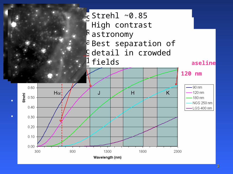
• The following galactic center images (from the current Keck AO The following galactic center images (from the current Keck AO system at 3.5 microns wavelength) illustrate KPAO’s intended system at 3.5 microns wavelength) illustrate KPAO’s intended capability at shorter wavelengths. In reality the resolution would also capability at shorter wavelengths. In reality the resolution would also improve (linearly with wavelength). improve (linearly with wavelength).
KPAO Baseline
120 nm
KPAO: Keck Precision AO KPAO: Keck Precision AO Strehl ~0.6 Compare to current AO at K, ~2x resolution (J vs. K)
Strehl ~0.2
Resolution 4x HST and collection gain 16x HST with 10 meter Keck
Strehl ~0.85 High contrast astronomyBest separation of detail in crowded fields
44
14 more years to go to reach “all AO all the time”
NSF-funded laser K1
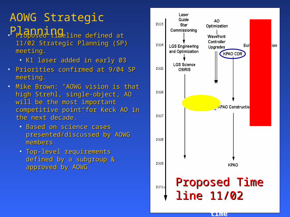
AOWG Strategic Planning
• Proposed timeline defined at 11/02 Proposed timeline defined at 11/02 Strategic Planning (SP) meeting.Strategic Planning (SP) meeting.
• K1 laser added in early 03K1 laser added in early 03
• Priorities confirmed at 9/04 SP Priorities confirmed at 9/04 SP meeting. meeting.
• Mike Brown: “AOWG vision is that Mike Brown: “AOWG vision is that high Strehl, single-object, AO will be high Strehl, single-object, AO will be the most important competitive point the most important competitive point for Keck AO in the next decade.” for Keck AO in the next decade.”
• Based on science cases Based on science cases presented/discussed by AOWG presented/discussed by AOWG membersmembers
• Top-level requirements defined Top-level requirements defined by a subgroup & approved by by a subgroup & approved by AOWGAOWG
Proposed Time line Proposed Time line 11/0211/02
55
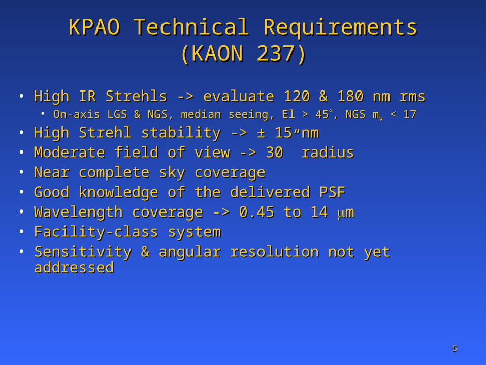
KPAO Technical RequirementsKPAO Technical Requirements (KAON 237)(KAON 237)
• High IR Strehls -> evaluate 120 & 180 nm rmsHigh IR Strehls -> evaluate 120 & 180 nm rms• On-axis LGS & NGS, median seeing, El > 45On-axis LGS & NGS, median seeing, El > 45, NGS m, NGS mvv < 17 < 17
• High Strehl stability -> High Strehl stability -> ± ± 15 nm15 nm• Moderate field of view -> 30” radiusModerate field of view -> 30” radius• Near complete sky coverageNear complete sky coverage• Good knowledge of the delivered PSFGood knowledge of the delivered PSF• Wavelength coverage -> 0.45 to 14 Wavelength coverage -> 0.45 to 14 mm• Facility-class systemFacility-class system• Sensitivity & angular resolution not yet addressedSensitivity & angular resolution not yet addressed
66
Science case Science case
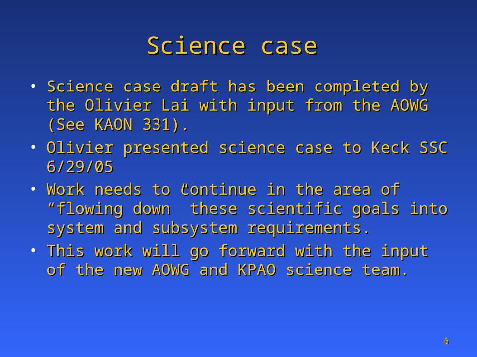
• Science case draft has been completed by the Olivier Lai Science case draft has been completed by the Olivier Lai with input from the AOWG (See KAON 331). with input from the AOWG (See KAON 331).
• Olivier presented science case to Keck SSC 6/29/05Olivier presented science case to Keck SSC 6/29/05• Work needs to continue in the area of “flowing down” Work needs to continue in the area of “flowing down”
these scientific goals into system and subsystem these scientific goals into system and subsystem requirements. requirements.
• This work will go forward with the input of the new This work will go forward with the input of the new AOWG and KPAO science team.AOWG and KPAO science team.
77
KPAO performance predictionsKPAO performance predictions
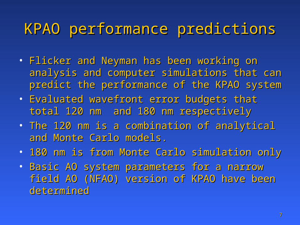
• Flicker and Neyman has been working on analysis and Flicker and Neyman has been working on analysis and computer simulations that can predict the performance of computer simulations that can predict the performance of the KPAO systemthe KPAO system
• Evaluated wavefront error budgets that total 120 nm and Evaluated wavefront error budgets that total 120 nm and 180 nm respectively180 nm respectively
• The 120 nm is a combination of analytical and Monte The 120 nm is a combination of analytical and Monte Carlo models. Carlo models.
• 180 nm is from Monte Carlo simulation only180 nm is from Monte Carlo simulation only• Basic AO system parameters for a narrow field AO Basic AO system parameters for a narrow field AO
(NFAO) version of KPAO have been determined (NFAO) version of KPAO have been determined
88
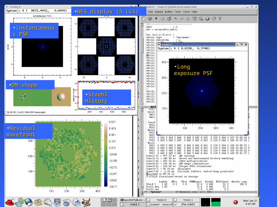
KPAO Monte Carlo simulationKPAO Monte Carlo simulation
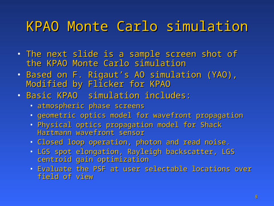
• The next slide is a sample screen shot of the KPAO The next slide is a sample screen shot of the KPAO Monte Carlo simulation Monte Carlo simulation
• Based on F. Rigaut’s AO simulation (YAO), Modified by Based on F. Rigaut’s AO simulation (YAO), Modified by Flicker for KPAOFlicker for KPAO
• Basic KPAO simulation includes: Basic KPAO simulation includes: • atmospheric phase screens atmospheric phase screens • geometric optics model for wavefront propagation geometric optics model for wavefront propagation • Physical optics propagation model for Shack Hartmann Physical optics propagation model for Shack Hartmann
wavefront sensorwavefront sensor• Closed loop operation, photon and read noise. Closed loop operation, photon and read noise. • LGS spot elongation, Rayleigh backscatter, LGS centroid gain LGS spot elongation, Rayleigh backscatter, LGS centroid gain
optimizationoptimization• Evaluate the PSF at user selectable locations over field of viewEvaluate the PSF at user selectable locations over field of view
99
•Long exposure Long exposure PSFPSF
•WFS display (5 LGS)WFS display (5 LGS)
•DM shape DM shape
•Residual Residual WavefrontWavefront
•Strehl HistoryStrehl History
•Instantaneous Instantaneous PSFPSF
1010
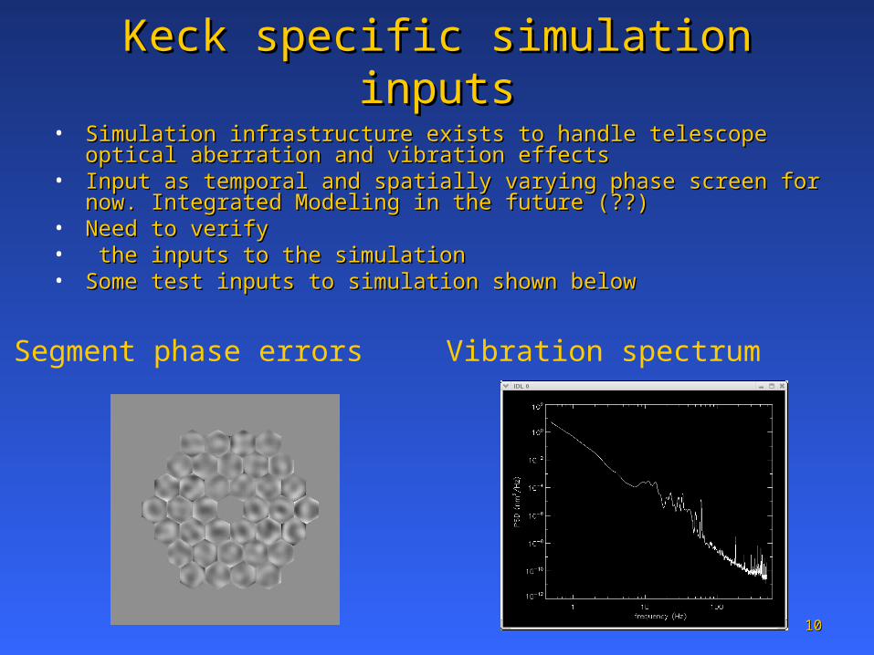
Keck specific simulation inputsKeck specific simulation inputs
Segment phase errors Vibration spectrum
• Simulation infrastructure exists to handle telescope optical aberration and Simulation infrastructure exists to handle telescope optical aberration and vibration effectsvibration effects
• Input as temporal and spatially varying phase screen for now. Integrated Input as temporal and spatially varying phase screen for now. Integrated Modeling in the future (??) Modeling in the future (??)
• Need to verifyNeed to verify• the inputs to the simulation the inputs to the simulation • Some test inputs to simulation shown belowSome test inputs to simulation shown below
1111
Large part of KPAO cost will be lasers Large part of KPAO cost will be lasers
• Need to understand Watts/$ tradeoffsNeed to understand Watts/$ tradeoffs• Obtained several year data set of Na Column densities for Obtained several year data set of Na Column densities for
Maui (Maui (http://eoslserver.csl.uiuc.edu/Research/Maui/NaLidar/index.htmlhttp://eoslserver.csl.uiuc.edu/Research/Maui/NaLidar/index.html))• Model for photon return from Na laser guide stars, included Model for photon return from Na laser guide stars, included
laser saturation effects (Both Pulsed and CW formats)laser saturation effects (Both Pulsed and CW formats)• Models compared to Keck/Gemini simultaneous LGS Models compared to Keck/Gemini simultaneous LGS
propagation on May 28 2005propagation on May 28 2005• Comparison between models and theory good to about 0.4 Comparison between models and theory good to about 0.4
magnitudes: magnitudes: • actual Na density is large uncertainty in verifying models actual Na density is large uncertainty in verifying models
1212
Sky CoverageSky Coverage
• Important to finalize requirement as it drives AO Important to finalize requirement as it drives AO architecture (NFAO vs. MOAO/MCAO)architecture (NFAO vs. MOAO/MCAO)
• Large sky coverage will requireLarge sky coverage will require• IR tracking detectorsIR tracking detectors• Some sharpening of NGSSome sharpening of NGS• Need to measure 3-4 NGS (tip/tilt only) or 1 NGS Need to measure 3-4 NGS (tip/tilt only) or 1 NGS
(tip/tilt focus/astigmatism)(tip/tilt focus/astigmatism)
• Using tools developed by Richard Clare for TMT Using tools developed by Richard Clare for TMT to evaluate KPAO sky coverageto evaluate KPAO sky coverage
1313
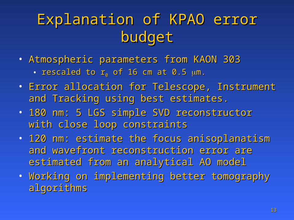
Explanation of KPAO error budgetExplanation of KPAO error budget
• Atmospheric parameters from KAON 303 Atmospheric parameters from KAON 303 • rescaled to rrescaled to r00 of 16 cm at 0.5 of 16 cm at 0.5 m.m.
• Error allocation for Telescope, Instrument and Tracking Error allocation for Telescope, Instrument and Tracking using best estimates. using best estimates.
• 180 nm: 5 LGS simple SVD reconstructor with close loop 180 nm: 5 LGS simple SVD reconstructor with close loop constraintsconstraints
• 120 nm: estimate the focus anisoplanatism and 120 nm: estimate the focus anisoplanatism and wavefront reconstruction error are estimated from an wavefront reconstruction error are estimated from an analytical AO model analytical AO model
• Working on implementing better tomography algorithms Working on implementing better tomography algorithms
1414
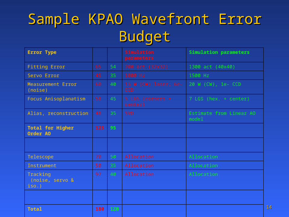
Sample KPAO Wavefront Error BudgetSample KPAO Wavefront Error Budget
Error Type Simulation parameters
Simulation parameters
Fitting Error 65 54 700 act (32x32) 1300 act (40x40)
Servo Error 45 35 1000 Hz 1500 Hz
Measurement Error (noise)
60 40 15 W (CW) laser, 6e- CCD
20 W (CW), 1e- CCD
Focus Anisoplanatism 58 45 5 LGS (corners + center)
7 LGS (hex. + center)
Alias, reconstruction 48 35 SVD Estimate from Linear AO model
Total for Higher Order AO
125
95
Telescope 70 50 Allocation Allocation
Instrument 50 35 Allocation Allocation
Tracking (noise, servo & iso.)
97 40 Allocation Allocation
Total 180
120
1515
SummarySummary
• Important to develop science requirements as Important to develop science requirements as part of the conceptual design process.part of the conceptual design process.• Therefore desire more community involvement.Therefore desire more community involvement.
• Performance analysis tools in place to do Performance analysis tools in place to do science/technical trade studies.science/technical trade studies.
• Emphasis soon to switch to system design Emphasis soon to switch to system design issues.issues.
1616
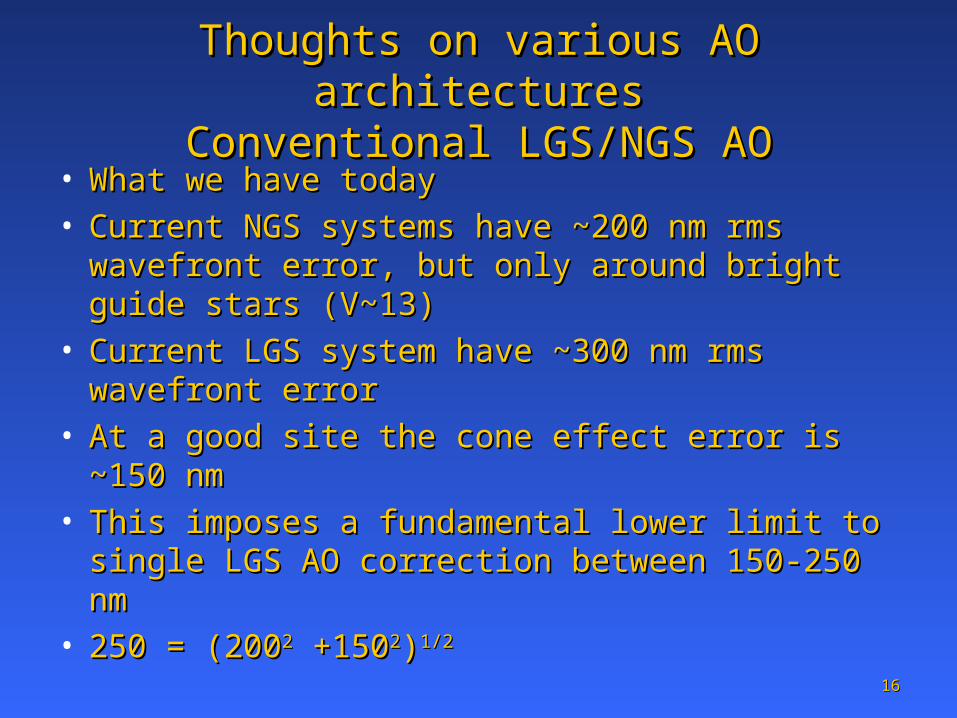
Thoughts on various AO architecturesThoughts on various AO architecturesConventional LGS/NGS AOConventional LGS/NGS AO
• What we have today What we have today • Current NGS systems have ~200 nm rms Current NGS systems have ~200 nm rms
wavefront error, but only around bright guide wavefront error, but only around bright guide stars (V~13)stars (V~13)
• Current LGS system have ~300 nm rms Current LGS system have ~300 nm rms wavefront errorwavefront error
• At a good site the cone effect error is ~150 nm At a good site the cone effect error is ~150 nm • This imposes a fundamental lower limit to single This imposes a fundamental lower limit to single
LGS AO correction between 150-250 nmLGS AO correction between 150-250 nm• 250 = (200250 = (20022 +150 +15022))1/21/2
1717
Thoughts on various AO architecturesThoughts on various AO architecturesExtreme AOExtreme AO
• One solution it to decide that NGS are the only One solution it to decide that NGS are the only viable reference sourceviable reference source
• A high Strehl system is still possible (i.e. XAOPI) A high Strehl system is still possible (i.e. XAOPI) • But now the number of targets is reduced to the But now the number of targets is reduced to the
brightest stars (V~9 or brighter)brightest stars (V~9 or brighter)• This is perfectly acceptable for certain types of This is perfectly acceptable for certain types of
very compelling observationsvery compelling observations• Extra-solar planetsExtra-solar planets
1818
Thoughts on various AO architecturesThoughts on various AO architecturesTomographyTomography
• Using multiple LGS to reduce cone effect was proposed Using multiple LGS to reduce cone effect was proposed in the original LGS paper (~1985)in the original LGS paper (~1985)
• Several variations have been proposed in recent yearsSeveral variations have been proposed in recent years• Multi conjugate AO (MCAO)Multi conjugate AO (MCAO)• Multi object AO (MOAO)Multi object AO (MOAO)• Narrow Field AO (NFAO)Narrow Field AO (NFAO)• Ground Layer AO (GLAO)Ground Layer AO (GLAO)
• These concepts all rely on measuring the volume These concepts all rely on measuring the volume turbulence above the telescope with several LGS turbulence above the telescope with several LGS
• The multi LGS measurement process has been named The multi LGS measurement process has been named tomography in analogy with medical imagingtomography in analogy with medical imaging
1919
Thoughts on various AO architecturesThoughts on various AO architecturesGLAOGLAO
• Measure volume turbulenceMeasure volume turbulence• select out only the turbulence at the ground and select out only the turbulence at the ground and
boundary layer (~ first km)boundary layer (~ first km)• Apply this correction with a single corrector at Apply this correction with a single corrector at
the telescope pupilthe telescope pupil• Field of view is large because turbulence Field of view is large because turbulence
correction at pupil is approximately the same for correction at pupil is approximately the same for all field angles all field angles
• wavefront error ~ 500 nm rms wavefront error ~ 500 nm rms
2020
Thoughts on various AO architecturesThoughts on various AO architecturesMCAOMCAO
• Measure volume turbulence with several LGSMeasure volume turbulence with several LGS• Approximate turbulence as occurring at several discrete Approximate turbulence as occurring at several discrete
altitudesaltitudes• Apply this correction with correcting elements that are Apply this correction with correcting elements that are
conjugate to each altitude conjugate to each altitude (from step above)(from step above)
• Field of view is large because turbulence correction is Field of view is large because turbulence correction is “applied” at altitude“applied” at altitude
• Cone effect reduced as well Cone effect reduced as well • wavefront error ~ 100-200 nm rms (field average)wavefront error ~ 100-200 nm rms (field average)• Fundamental limits set by tomography, number of Fundamental limits set by tomography, number of
correctors and need for NGS tip/tilt starscorrectors and need for NGS tip/tilt stars
2121
Thoughts on various AO architecturesThoughts on various AO architecturesMOAOMOAO
• Measure volume turbulence with several LGSMeasure volume turbulence with several LGS• Select preferred directions for correction, i.e. science objects and Select preferred directions for correction, i.e. science objects and
possibly tip/tilt NGSpossibly tip/tilt NGS• Apply each direction optimized correction with a optic that is unique Apply each direction optimized correction with a optic that is unique
to that direction (field separated) to that direction (field separated) • Correction is only applied at interesting locations in a large field of Correction is only applied at interesting locations in a large field of
view: don’t correct blank sky!view: don’t correct blank sky!• As currently conceived LGS AO light is open loopAs currently conceived LGS AO light is open loop• This requires linear AO correctors and wavefront sensing over a This requires linear AO correctors and wavefront sensing over a
large dynamic rangelarge dynamic range• Required technology has yet to be demonstrated/testedRequired technology has yet to be demonstrated/tested• UCSC is doing conceptual design of MOAO for TMT UCSC is doing conceptual design of MOAO for TMT • Fundamental limits set by tomography, non linearity of AO system Fundamental limits set by tomography, non linearity of AO system
elements and need for NGS tip/tilt starselements and need for NGS tip/tilt stars
2222
Thoughts on various AO architecturesThoughts on various AO architecturesNFAONFAO
• Measure volume turbulence with several LGSMeasure volume turbulence with several LGS• Select correction needed for on axis objectsSelect correction needed for on axis objects• Corrected field of view smallCorrected field of view small• System can run closed loop around LGS with proper System can run closed loop around LGS with proper
reconstruction matrixreconstruction matrix• System upgrade to full MCAO straightforwardSystem upgrade to full MCAO straightforward• Wavefront error 50-120 nm rms Wavefront error 50-120 nm rms • Fundamental limits set by tomography and need for NGS Fundamental limits set by tomography and need for NGS
tip/tilt starstip/tilt stars