
CALCULATION OF SHAFTS IN MARINE APPLICATIONS · PDF file~ool-V022 CLASSIFICATION NOTES No....
28
V022 CLASSIFICATION NOTES No. 41.4 CALCULATION OF SHAFTS IN MARINE APPLICATIONS JANUARY 2001 DET NORSKE VERITAS Veritasveien l, Norway Tel.: +47 67 5799 OOFax: +47 67 57 99 11
Transcript of CALCULATION OF SHAFTS IN MARINE APPLICATIONS · PDF file~ool-V022 CLASSIFICATION NOTES No....
~ool- V022
CLASSIFICATION NOTES
No. 41.4
CALCULATION OF SHAFTS IN MARINE APPLICATIONS
JANUARY 2001
DET NORSKE VERITAS
Veritasveien l, N-1322H~vik, Norway Tel.: +47 67 5799 OOFax: +47 67 57 99 11

FOREWORD
DET NORSKE VER IT AS is an autonomous and independent Foundation with the objective of safeguarding life, property and the environment at sea and ashore.
DET NO RS KE VER IT AS AS is a fully owned subsidiary Society of the Foundation. It undertakes classification and certification of ships, mobile offshore units, fixed offshore structures, facilities and systems for shipping and other industries. 111e Society also carries oul research and development associated with these functions.
DET NORSKE VERITAS operates a worldwide network of survey stations and is authorised by more than 130 national administrations to cm-ry out surveys and, in most cases, issue certificates on their behalf.
Classification Notes Classification Notes are publications that give practical information on classification of sl1ips and other objeccs. Examples of design solutions, calculation mechods, specifications of test procedures, as well as acceptable repair methods for some components are given as inteipretations of the more general rule requirements.
A list of Classification Notes is found in the latest edition of the Introduction bookl.ets to the "Rules for Classification of Ships", the "Rules for Classification of Mobile Offshore Units" and the "Rules for Classification of High Speed and Light Craft". In "Rules for Classification of Fixed Offshore installations", only those Classification Notes that are relevant for this type of structure, have been listed.
The list of Classification Notes is also incl.uded in the current "Classification Services - Publications" issued by the Society, which is available on request. All publications may be ordered from the Society's Web site http://exchange.dnv.com.
Comments may be sent by e-mail to [email protected] For sub.~cription orders or information about subscription terms, please use [email protected] Comprehensive information about DNV and the Society's services is found at the Web site hllp:l/www.dnv.com
©Oct Nor.~ke Ventas Computer Typesetting (FM+SGML) by Det Norske Veritas Printed in Norway by GCS AS.
If any parson suffers loss or damage which is proved lo have been causecl by any negligent act or omission of Det Norske verlles. lhen Det Norske Veritas shall pay compensation to such person for his provecl clirect loss or damage. However. the compensation shall not exceed an amount equal lo ten times the lee charged for the service in question, provided that the maximum compen· sation shall never exceed USO 2 million. In this provision ·oet Norske Veritas• shall mean t'1a Foundation Del Norske Veritas as well as all its subsidiaries, directors, officers, employees, agents and any other acting on behalf of Del Norske Verilas .

Classification Notes - No. 41 . 4
Januar 2001
3
CONTENTS
1. 1.1 1.2 l.3 2. 2.1 3. 3.1 3.2 3.3 3.4 3.S
4. 4.1 4.2 4.3 4.4
BASIC PRINCIPLES ............................................... 5 5. THE TRANSIENT VIBRATION CRITERION . 11 Scope ........................................................................... 5 Description of Method ............................................... 5 Limits of Application ................................................. 6 NOMENCLATURE ................................................. 6
5.1 Scope and General Remarks .................................. 11 5.2 Basic Equation ......................................................... 11 6. THE GEOMETRICAL STRESS
CONCENTRATION F'ACTORS .......................... 13 Syinbols ....................................................................... 6 THE LOW CYCLE FATIGUE CRITERION ....... 7 Scope and General Remarks ....................... - ........... 7 Basic Equations ............................................. ............. 7 Repeti tive Nominal Peak Torsional Stress, 'Z'max· .... 7 Repetitive Nominal T orsional Stress Range, l:!.7: ...... 7 Component Influence Factor for Low Cycle Fatigue, KL ................................................................. 9 THE HIGH CYCLE :FATIGUE CRITERION .... 10
6.1 Definition and General Remarks ........................... 13 6.2 Shoulder Fillets and Flange Fillets ....................... 13 6.3 U-Notch .................................................................... 14 6.4 Step with Undercut ................................................. 15 6.5 Shrink Fits ................................................................ 15 6.6 Keyways .................................................................... 16 6.7 Radial Holes ............................................................ 17 6.8 Longitudinal Slot ..................................................... 17
Scope and General Rcmarks ................................... t 0 Basic Equation ......................................................... 10
6.9 Splines ....................................................................... 18 6.10 Square Groove (Circlip) ......................................... 19
High Cycle Fatigue Strengths, -rr and or ................ 10 Compom~nt Influence Factor for High Cycle APPENDIX A F atigue, KH-.and ~a-............................................. 10 EXAMPLES ....................................................................... 20
DET NORS.Kl:: VERITAS

4
Dl:ff N ORSKE VERITAS
Classification Notes - No. 41.4
January 2001

Classification Notes - No. 41.4
January 2001
1. Basic PrincipJes
1.1 Scope This Classification Note consists of the procedure and the basic equations for verification of the load carrying capacity for shafts. It is mainly based on the DlN 743 Part l-3: 2000-04 and VDEH 1983 "Synlhetische Wohlerlioien" but "adapted" to marine applications, such as marine propulsion and auxiliaries
102 103 104 105 106 107
Figure 1-1 Applicable load cycles
1.2 Description of Method Figure 1-1 describes the typical ranges of load cycles to be considered for shafts in marine applications.
A represents the "primary cycles" occurring when full load is applied for forward operation . For reversing plants (reversing direction of rotation) the stJess range is also to inelude the negative torque. The range J03 to 104 is typical, but for certain applications, as for example short range ferries, higher number of cycles may have lo be considered. For the method referred to as " low cycle criterion" 104 is used.
B represents no1mal, continuous operation. The number of cycles is associated with the number of revolutions throughout the vessels lifetime, i.e. 109 to I oto. In the following this is referred to as the "high cycle criterion".
C represents regular transient operations lhaL are noc covered by A. In practice this means direct coupled plants with a speed range baned for continuous operation. Sven though such barred speed ranges shall be passed as quickly as possible, certain plants may accumulare as much as I 06 cycles, either due to frequent passing or due to slow acceleration. On the other hand, optimised plants may accumulate as few cycles as 104.
For optimisation of a shafting system, in panicular when transient operations are concerned, it is advised to use an iterative approach between dynamic analyses (the Rules for Classification of Ships Pl.4 Ch.3 Sec. I G) and shaft design.
Torsional and bending stresses are to be considered, but axial stresses are considered negligible for marine shafting systems.
1.2.1 Fatigue values and safety factors The empirical fonnulae for fatigue strength arc based on average values, i.e. 50% survival probabiUty. The correlation between fatigue strength and mechanical strength is a simple function of the yield strength (or 0,2% proof stress). This is
5
onboard ships and mobile offshore units. "Adapted" means lhaL simplifications have been made, such as direct use or mechanical strength from representative testing, and that lifecycle considerations are made for a limited number of stress cycles.
The permissible stresses in the different shafts depend on the safety factors as required hy the respective rule sections.
Welded shafts are not covered in this Classification Note.
106 N Number of cycles
A = Range for start·full load-stop cycles
B =Range for cycles due to reversed bending and/or torsional vibrations for conlinuous operation
C = Range for transient cond· itions as passing through barred speed ranges
documented to result in the smallest standard deviation, see VDEH 1983.
Since run outs are normally not pursued beyond 107 cycles, and it is known that the fatigue scatter increases with higher number of cycles, higher safety factors are used for high cycle fatigue than for low cycle fatigue.
Somewhat higher safety factors are also chosen for shafts with considerable uncertainties in the stress assessment and when there is limited accessibility, as for example propeller shafts.
Main differences to previous DNV practice
As mentioned above, safety factors are made dependent on number of cycles. Stress concentrations and surface roughness influence are combined in a more modern way. The old method where the single influence factors were multiplied did not give justice to the interdependence. The old method would only be reasonably correct when smooth surfaces were combined with various stress concentrations, or rough surfaces combined with low stress concentrations. Rough surfaces combined with high stress concentrations would be too conservative. The fatigue strength depends on the actual mean stress. As in DIN 743 the mean stress is taken as the equivalent stress (combined torsion and bending). This results in a somewhat stronger mean stress dependence than previously. The low cycle criterion is now based on I 04 cycles versus I OJ previously.
Simplified methods for some applications are presented in the Rules for Classification of Ships.
For the purpose of demonstration, a few examples of the calculation methods are presented in Appendix A.
OET NORSKE VERITAS

6
1.3 Limits of Application The criteria presenlcd in thi.s Classification Note apply to shafts with:
material of forged or hot rolled s teels w ith minimum tensile s trength of 400 MPa material tensile strength, Oh up to 1200 MPa1) and yield strength (0,2 % proof' stress), O'y up to 900 MP a 1)
no surface hardening (which will require special consider;ttions)
no chrome plating, metal spraying, etc. protection against c01rosion (th rough oil, oil based coating, paint, material selection or dry atmosphere).2)
1) .for applications where it may be ncce~~ary Lo take the advantage of lensil e strength above goo MPa a11d yield strength ahove 600 M J!H, material d eanliness has an increasing imponnncc. Higher cleanliness than specified hy material standnrds mny be required. Sec also the Rules l<ir Classification of Ships Pc.4 Ch.2 Sec.5.
2) Furthermore, special protection against corrosion is required. Method of protection is lo be approved.
2. Nomenclature
2.1 Symbols The symbols in Tahle 2-1 are used . Only Sl units are used.
Ta ble 2-1 Symbols
Symbol Term Unit a;. Geometrical stress concetllralion -
factor, lor.~ion
ab Geometrical stress concentration factor, bending
-
A. Rotational speed ratio = n/n0 -61' Repcti.tivc nominal torsional MPa ( = N/mni2)
slress range
T Nominal mean torsional stress at MPa (= N/nun2) any load (or r .p.m.)
'f'Q Nominal torsional stress at max-imum conlinuous power
MPa (= N/mm2)
iJcc rev Tori;i{mal stress due to ice shock MPa (= N/nun2) while running astern
'Zinax Repecitive nominal peak torsion- Ml'a (= N/m1u2) al ~tress
'rvT Pennissible torsional vibration stress amplitude for transient
MPa (= N/mm2)
condition
~nax reversed Maximnm reverse<l ton;ional MPa (= N/mm2) stress
1'v Nominal vibratory torsional MPa (= N/mm2) stress amplitude
'tf High cycle fatigue ~'tl'Cngtl1 MPa (= N/mm2)
'tvHC Permissible high cycle torsiornll vibration stress amplitude
MPa (= N/mm2)
'Z'vJ.C Permissible low cycle torsional v ibration stresi; amplitude
MPa (= N/nun2)
Oil Nominal reversed bending stress amplitude (rotating bending stress amplitude)
MPa (= N/min2)
O'H Ultimate tensile strength I) MPa (= N/mm2)
O'f High cycle bending fatigue MPa (:: N/mm2) strength
ay Yield strength or 0.2% pr()o f stress I )
MPa ( = N/mm2)
b Width of square groove (circlip) mm d Minimum shaft diameter at mm
notch
d; l nncr diamecer of shaft al. notch mm
Classification Notes - No. 41.4
January 2001
Tublc 2-1 Symhol1> (Continued)
Symbol Term Unit
d1i Dia.meter of hole mm [) Bigger diameter in way of notch mm
e Slot width mm
Ji.< a;.. ay) Nocch sensitivity term for low -cycle fatigue
A<Ry,CTn) Surface condition innuencc term -for low cycle fatigue
fH/l4,m1) Notch influence term for high cycle tor:sional fatigue
-
jj~J.ai:i.mtJ Notch influence term for high cycle bending fatigue
-
f tt(r) Size (statistical) influence term for high cycle fatigue
.
f i-i i<Rr O".s) Surface condition influence term -for high cycle torsional fatigue
fiiJ Ry, O'o) Surface condition influence term -for high cycle bending fatigue
k,~, Bccentricity ratio -6.K" Applkation factor, torque range -KA Application factor, repetitive cy- -
clic torques
KAP Application factor, temporary nccasional peak torques
.
KA ice Application factor, ice shock tor- -q11es
Kua Component in n uence factor for high cycle bending fatigue
-
KH'I' Component influence factor for high cycle torsional fatigue
-Kr. Component influence factor for
low cycle fatigue -
[ Total slot length mm
mb Notch sensitivity coeffi '-ient for high cycle fatigue (bending)
.
m, Notch sensitivity coefficient for h igh cycle fatigue (torsion)
-
n Actua l shaft rotational speed, minutes· I r.p. m.
no Shuft rotational speed at maxi-mum continumts power, r.p.m.
minutes· 1
Ne Accumulated number of load cy- -cl cs
Ne Accumulated number ()f load cy-cle.~ <luring one passage 11p and
-down
p Maximum continuous power kW
r Notch radius mm
r .. Radius t.o eccentric axial horc mm
R~ S urface roughness, arithmetical mean deviation of d1c profile
JIJ11
Ry Surface roughness, maximum µm height of the profile (peak to val-ley)
s Safely factor -t T hickness mm
Tv Nominal vibratory torsional torque amplitude
kNm
To Torque at maximum continuous kNm power
w1 Cross sectional modulus (first inomenl of area), torsion
mm3
l} For represencativc ccst pieces according to the Rules for Classi licalion of Ships Pt.2 Ch.2 Sec.5 .
D ET NORS'KE VEl<JTAS

Classitlcation Notes - No. 41.4
January 2001
7
3. The Low Cycle Fatigue Criterion •o = nominal torsional strel;s at maximum continuou~ power calculated as:
3.1 Scope and General Remarks The low cycle fatigue criterion is applicable for shafls subject to load conditions, which accumulate 103 to 104 load cycles. Typical low cycle fatigue load conditions arc:
T0 · 106
16 d T 0 · 106
= w 4 4 r n(d - d;)
Load variations from: KA = application factor, repetitive cyclic torques defined as:
z,cro to full forward load zero to peak loads such as clutching-in :;hock loads, electrjc motor start-up with scar-delta shift, ice shock loads (applicable for ships with ice class nolations), etc. reversed load to ful I forward load.
The bending stress iniluence is normally negligible because bending stresses are normally associated with the number of shaft revolutions (rotary bending stresses) and thus with high cycle fatigue, see 4. However, for certain applications where stochastic bending moments of high amplitudes but few cycles may occur (i.e. bending stresses as for example in water jets), the bending influence should be taken into account, see 3.3.
Simplified diamete.r fonnu lac arc given in lhe Rules for C1as.sificat1cm of Ships Pt4 Ch.4 Sec. I R206 to B208 for various common shaft designs. However, since lhe simplifications are made "Lo Lhe safe side", these formulae will re.suit in somewhat larger dimensions than the basic criterion presented here.
3.2 Basic Equations The peak stresses are limited to:
Fur all ~hafts:
Additionally, for shafis in r~versible plants:
0.85 O"y
Ll-r:5: S KL
"llnax
s
= repetitive nominal peak torsional stress according to 3.3
= repetitive nominal torsional stress range according to 3.4
= yield strength or 0.2 % proof stress linrited to 0, 7 a13 •
This limitation is introduced for the calculalion purpose only, since further "irrational" increase of the yield strength (by the steel heat treatment) increases the risk for brittle fracture.
= required safety factor according to the Rules for Classification of Ships (January 2001, S = 1.4)
= component influence factor for low cycle fatigue according to 3.5.
3.3 Repetitive Nominal Peak Torsional Stre.'>S, 'linax
For geared plants:
Trnnx = "'cl KA or i-u KAP or •o KAice whichever is the highest, sec Figure 3-1
For direct coupled plants:
'!max = max irn um val uc of ( 1: + 'fv) in the entire speed range (for fwd running) or To KA ice whichever is the high~t, sec Figure 3-2.
KAP =
KAice =
'X"v
Sec Classification Note 41. 2 application fact.or, temporary occasional peak torques, see Classification Note 41.2 application factor, ice shock torques, see Rules for Classification of Ships l't.5 Ch. I and Classification Note 41.2 nominal vibratory torsional stress amplitude for continuous operation, see Rules for Classification of Ships Pt.4 Ch.2 Sec. 1 Table Al.
The innucncc of any stochastic bending moments of high amplitudes (but few cycles) may be taken into account simply by multiplication of -r0 with:
I (<rh)2 I+- -
3 "ro
This simplification is justified because the estimation of these stochastic bending moments is very uncertain and conservative, see Rules for Classification or Ships Pt.4 Ch.4 Sec. I F301 item 2.
3.4 Repetitive Nominal T01·sional Stress Range, /).. -r Only applicable to reversible plants.
For geared plants:
.1.KA = Application factor, torque range defined as:
= K A (P)(ice) fii + Tmax reversed
•o
As a safe simplification it may be assumed that ..1KA = 2 KA or 2 KAP or 2 KA ice whichever is the highest.
For direct coupled plants: ..1-r= 'linax +'!max reven;ed, sec Figure 3-3.
"t;nnx = maximum value or ( !" + 'fy) in the entire speed range (for fwd running) or ro KAice
whichever is the highest
'Zinux reversed maximum reversed tor:;ional stress, which is the maximum value of ( i- + t'v) in the entire speed range (for astern nmning) or 'lice rev (for astern mnning) whichever is the highest
Ll '! = repetitive nominal torsional stress range is equal to the maximum forward torsional stJess plu~ the maximum reversed torsional stress.
As a safo simplirication it may be assumed that 6. -r= 2 ( r + rv) or 2 7:0 KA ice whicheveris the highest.
DET NORSKE Vl.iRffAS

8
Figure 3-1
To~ional stress ~--- Clutching in---+---
Typical torsional stresses in sbafts for geared plants
Figure3-2
Torsional stress
'to --------
Typical torsional stresses in shafts for direct coupled planL~
Classification Notes - No. 41 .4
January 2001
Normal operation (MCR)
KA;ce •o~ ki.:~hock ~
time
Vibration Stress (Synthesis)
~
n0 r.p.m.
Der NO RS KE VER IT AS

Classification Notes - No. 41.4
January 2001
Figure 3-3 Stress range
Torsional stress
Nominal
forward t
~ r.p.m.
_./Nominal / ! reversed t
I
9
3.5 Component Influence Factor for Low Cycle <7y Fatigue, KL
yield strength or 0,2% proof stress limited to 0,7 OR· This limitation is introduced for the calculation purpose only, since further "irrational" increase of the yie ld strength (by the steel heat treaunent) increases the risk for brittle fracture.
The component influence factor for low cycle fatigue takes into account the difference in fatigue strength of the actual shaft component and a polished plain test specimen push - pull loaded. The empirical formula is:
fL(Ut_, O'y) =
Ji. (Ry, O:S) =
notch influence term for low cycle fatigue including notch sensitivity, see 3.5. I surface condition influence tenn for low cycle fatigue, see 3.5.2.
3.5.1 Notch influence term for low cycle fatigue,/i,(lJ:t, 6y) This notch influence term is a simplified approach that reflects the increasing influence of a notch with increasing material strength:
3.5.2 Surface condition influence term for low cycle fatigue,! d R y,<7B)
This surface condition influence tenn is a simplified approach that reflects the increasing int1uenee of surface roughness for high material strength.
For ordinmy steels: -4
f1.(Ry,<7a) = 10 (CJ'.'R - 200)logRY
For stainless steel exposed to sea water:
.fi.,(Ry,O'B) = 4 · I0-4(a8 - 200) logRY
geometrical stress concentration factor, torsion ac- Ry cording to 6
= surface roughness, maldmum height of the profile (i.e. peak to valley)"' 6 R3 .
DF.T N ORSKE VEIUfAS

10
4. The High Cycle Fatigue Criterion
4.1 Scope and General Remarks The high cycle fatigue criterion is applicable for shafts subject to load conditions, which accumulate more than 3· l 06 load cycles, but typically 109 to 1010. Tl is based on the combined vibratory torsional and rotating bending stresses (axial stresses disregarded) relative to the respective component fatigue sirengLhs. T ypical high cycle fatigue load conditions are:
Lu;ni nuiaiiu11:s <lut: to wrsionai vibrations appiicabie for continuous operation, see the Rules for Classification of Ships Pt.4 Cli.2 Scc. l Table A I und rotating bending moments due to forces from gear mesh and forces listed in the Rules for Classification of Ships Pt.4 Ch.4 Sec. I f300. Load variations (torque and bending moment) due to ice impacts on the propeller for ice dassed vessels, see the Rules for Classification of Ships Pt.5 Ch. I.
Simplified diameter formulae are given in the Rules for Classification of Ships PL.4 Ch.4 Sec. l B206 to A208 for various common shaft designs . However, since the simpl ifications arc made "to the safe side", these formulae will result in somewhat larger dimensions than the basic c1iterion presented here.
4.2 Basic Equation The high cyde dynamic stresses are limi ted to:
('"·)2
(O'h)2
l - + - $;-
't'f O'f s2
'2\,- = nominal vibratory torsional stress for continuous operation.
For geared plants: To (KA - 1) unless a higher value applicioi below the full speed range (-90%-100% engine speed).
For ice class: ro (K Aico - I) . 't'r = high cycle 1orsional fatigue strength, see 4.3 q, = nominal reversed bending stress amplitude, see 4.1 O'f high eye.le bending fatigue strength, sec 4.3 S = required safety factor according to the Rules for
Classil'ication of Ships (January 2001, S = 1,6) .
4.3 High Cycle Fatigue Strengths, 'fr and O"'f
For ordinary steels, the high cycle fatigue sl.rcngths in bending and torsion arc based on empi1ical formulae. For reversed stresses, the fatigue strength is presented as a linear function (e.g. 0,4 O'y+ 70) of the main parameter which is assumed to be the yield strength (see VDEH 1983). The mean stress influence is in principle the applied equivalent (von Mises) mean stress, but for marine shafting this means in prnctice a function of the mean torsional stress. Finally, the fatigue strengths are reduced hy the component influence factor.
For stainlc."'" steel operating in seawater, Lhe fatigue strengll1s are dependent on the expected number of load cycles. Test rcsult.o.; are used as basis for the given figures, but are somewhat on U1c safe side in order lo compensate for !he i_nfluence of 1he mean stress (thus the mean stress influence is not inco11mrat.ed as a separate parameter in these fonnulae).
Classification Notes - No. 41 .4
January 2001
For stainless steel not exposed to corrosive environment, the criteria for ordinary steel apply.
Table 4·1 Fatigue strength
~) ... 1()8 l o9-1010
M
•r = 0.24 (J'y + 42 - 0.15 ..
u • ".H 'l'
Ordinary sleeli;
O'r = 0.4 (J'~ + 70 - 0.4 ..
KHa
105 90 't f = -- 'tf = --
Kur Klir Stainless sl.t:cl f2)
(in sea water) 16:5 140
(J'f = -- O'f = --Kua KHa
118 97 'tf = -- 'tr = --
KH-r Kur
Stain less steel II2) and 1112) (in sea w atcr)
184 150 O'f = -- O'f = --
KHO' KUO'
l) 'file nwnht:r of cycles t'cfcrs to thosi: accumulated in the full load range. 1()8 is a suitable estimate for e.g. plcasucc craft. 109 l0 LQIO should be used r01· ferries, etc.
2) Stainless sletl I= nustcnitic steels with 16-18 % Cr, 10-14 % Ni and > 2% Mo with O'fl = 500-600 MPa and (TY> 0,45 a13 SLainles~ steel 11 = martcusitic.: steels with 15-17 % Cr, 4-6 % Ni And > I% Mo wilh <rp = 850-1000 MP:1 und <1. > 0,75 a8 S1ainlcss i.icel II - ferritic-austenitic (dupfcx) steels with 25-27 % Cr. 4-7% Ni and 1-2% Mo with o-8 = 600 to 750 MPa and O'y > 0,65 0'9. For 01her kinds of stainless slcel. special consideration applies to fntigue values and pining resistance, see the Ruic.~ for Classificmion of Ships PL4 Ch.-4 Sec. I 0204
cry = yield s trength or 0.2% proof stress limited to 0.7 a8 . This limitation is introduced for U1c calculation purpose only, since further " irrational" increase of the yield strength (by the steel heat treatment) increases the risk for b1ittlc fracture.
KHr component influence factor for high cycle torsional fatigue, sec 4.4
KHO' component influence factors for high cycle bending fatigue, sec 4.4
T nominal mean torsional str.ess al any load (or r.p.m.).
4.4 Component lntluence Factor for High Cycle Fatigue, KH-rand KH<T
The component influence factor for high cycle fatigue takes into accoum the difference in fatigue strength of the actual shaft component and a polished plain lest specimen push - pull loaded. The empirical formulae are :
Torsion:
Rending:
KHr == fI1 i at, mt) +.ff.r(r) + f H!Ry, 0'9)
KHa = fnJab, mh) + ftt(r) + f ttJRy,aF!)
DF.T NORSKE VRRITAS

Classification Notes - No. 41.4
January 2001
.ff.1/£1i,m1)
fHJ%,mb)
f H(r)
I H i(RY'<T13)
fi1JRY'Ofi)
= notch influem:c tcnn for high cycle torsional fatigue, see 4.4.1
= notch influence term for high cycle bending fatigue, see 4.4.1
= si1.e (statistical) inlluence term for high cycle fat igue, see 4.4.2
= surface condition influence term for high cycle torsional fatigue, see 4.4.3
= surface condition influence tenn for high cycle bending fatigue, sec 4.4.3.
4.4.1 Notch influence term for high cycle fatigue,J8 ;.a.,
11
For ordinary steels:
torsion: -4
.fH1<Ry,a13) = 3. JO (CJa -200)1ogR Y
Reruling: ! HJRy,aB) = 4· 10-4(aB-200)log'l{y
For stainless szeel exposed to seawater:
Torsion and bendi11g: -3
/11't(Ry, aB) = f H a<RY'aB) = l 0 ( O'B - 200)log RY
mt) andfHcf <Xfi, mh) Ry = surface roughness, maximum height of the profile (i.e. peak to valley)"' 6 Ra· This term represents the influence of the geometrical stress
concentration, a and the notch sensitivity, m, which represents the notch factor when they are combined as afrn.
For multjradii tran.'>itions, sec 6.2, resulting in low geometrical stress concentration factors (- 1.05), m 1 and rnb = 1.0. If the calculated value offH./~.m1) or fiio(O'"b,mh) i.o,; below unity, the value 1.0 is to be used.
Torsion: at
.fH (at' mt) = -t TI\
a1 geometrical stress concentration factor, torsion according to 6
mt = notch sensitivity c<Jcfficient for high cycle torsional
Bending:
fatigue, calculated as:
ml = I + ( 60 - 0.05) fl
(jy >./~
ab fHa(llb,mb) = -
mb ab geometrical stress C()nccntration factor, bending ac
cording to 6 m0 notch sensitivity coefficient for high cycle bending
fatigue, calculated as:
mb = 1+(60- 0.05) f?:.
(jy >J; 4.4.2 Size (statistical) intluence term for high cycle fatigue, fR(r)
This term represents a size factor, which qualitatively takes into account the amount of material subject to high stresses. It does not represent the stress gradient influence since that is included in the notch sensitivity coefficient, m, above. Further, it doe.s not consider Lhe reduced material strength due to size since that is covered by requirements of testing representative specimen from forgings.
r = notch radius (use d1/2 or e/2 for radial holes or sloLc;, respectively, see 6.7 or 6.8) or shaft radius whichever is smaller. 1f r > J 00, l 00 is to be used.
4.4.3 Surface condition intluence term for high cycle fatigue, /H:-r\Ry, CIJl) and f 8 JRy, a8 )
This term takes the surface roughness into account. The surface roughness due to the machining constitutes a kind of stress concentration and reduced fatigue strength compared with a polished test specimen. The smface condition influence is higher for more notch sensitive, high strength steels.
5. The Transient Vibration Criterion
5.1 Scope and General Remarks The transient vibration criterion applicable to vibration levels when passing through a barred speed range applies in practice only to direct coupled plants. The permissible torsional vibration stress amplitudes, 'fvT are determined by logarithmic interpolation between the low cycle criterion ( rvLd and the high cycle criterion CrvHC) depending on the accumulated number of cycles Ne during the foreseen lifetime of the plant.
Barred speed ranges arc only permitted below a speed ratio A= nlno = 0.8 where n = actual r.p.m. and no = r.p.m. at full power.
Simplified diameter formulae are given in the l{ules for Classification of Ships Pt.4 Ch.4 Sec.1 B208 for some specific shaft dc.o,;igns.
5.2 Basic Equation
0.41og(f'v l.CJ
( ~ f'vlld
3·10 'X'vT :::; 'X'vHC ~
_ (NcJ0.4log(::~~) - 'X'vLC 4
10
'rvl!C
rvLC
= pcnnissible high cycle torsional vibration stress am-p litude calculated according to the criteria in 4. with a safety factor of l.5 (January 2001) but without the bending stress influence.. For propeller shafts in way of and aft of the afl stern tube bearing the bending influence is covered by an increase of S by 0.05
= permissible low cycle torsional vibration stress am-plitude calculated according to the criteria in 3. with a safety factor of 1.4 (January 2001). For propeller shaft., in way of and aft of the aft stern tube hearing the bending inl1uence is covered by an increase of S by 0.05
= accumulated number of load cycles (104 < Ne < 3· lu6). For determination of the relevant Ne. see the Rules for ClassiJicalion of Ships Pt.4 Ch.3 Scc. l 0401 c and f, or a detailed method in 5.2. l and 2.
5.2.l The accumulated number of cycles, Ne The accumulated number of cycles, Ne is to be based upon an equivalent number of cycles U1at results in the same accumulated partial damage (Miner's theory) as the real load spectrum.
The procedure is as follows:
I) Record transient torsional vibrations, sec Figure 5-1 and Figure 5-2.
om· NORSKE VERITAS

12 Classification Notes - No. 41 .4
January 2001
----------:::_1_~0-~- 90% -----------80%
------------ -- - -- --- - -- -------------80% ---- -- --- ------ 90°/ri
------------ ---- - ----------~00% .
Figure 5-1 'fv during stopping
- ---- --------------100% - - - - - - - - - - - - - - - ---- - - - - --90%
----- - ----- - - ----· 80%
---------------------80% --- ------- -- - -------- - ------------ 90%
------- -- -------------------100%
Figure S-2 -r, during starting
2) Determine the maximum double amplitude 'f"y considering both start and stop and use lhi!'i as reference for 100%.
3) Draw lines in both start and stop rcconls with double amp litude 100%, 90%, 80% and so on, see Pigure 5-1 and Figure 5-2.
4) Count number of cycles N JOO between 90% and 100%. This range will then be eomndered as amplitudes of 100%. Count number of cycles N90 between 80% and 90%.
This range will then be considered as amplitudes of 90%, and so on.
5) Determine the double Jogarilhmic.; -r-N curve by means of "Z"vLC and XVHC> see Figure 5-3.
'tvllC
Figure 5-3
! ! I I i
----t--······--·-·-
1 i I
i j i ! '
104
Double logarithmic -r-N curve
DRT NORSKC VERlTAS
n time
time
N 3-106

Classification Notes - No. 41 .4
January 2001
With this characteristic the equivalent number of cycles with 100% amplitude are calculated by means of division of the counted cycles with denominators detennincd as:
90% level with denominator
80% level with denominator
70% level with denominator
6) Calculate the equivalent number of cycles for one pa.o,;sage up and down as:
N90 Ngo N?O
Ne = N 100 + [ ~ + [ ~ + [ ~ log :vL<.: log ;vL(; log ;vLC
'!"vii 'l"vH 'fvH , 1.3 1.7 2.4
7) Determine accumulated number of cycles Ne as Ne times number of passages, see 5.2.2.
5.2.2 Number of passages This equivalent number of cycles for passing up and down through the barred speed range is to be multiplied with the expected number of passages during the foreseen life time of the ship.
Unless substantiated by particular foreseen service spectrum, the followi ng number of passages (up and down together) may be used for lhe various kinds of vessels:
Large carriers with fixed pitch propeller and manoeuvring speed below the barred speed range respectively with con-
13
trollable pitch propeller. Once every week, resul ting in a total of 1000 passages. Large carriers with fixed pitch propeller and manoeuvring speed above U1e barred speed range. Five times every week, resulting in 5000 passages. Vessels for short trade, once every day, resulting in 7000 passages. Ferries for short distances, 20 times per day, resulting in 150000 passages.
6. The Geometrical Stress Concentration Factors
6.1 Definition and General Remarks The stress concentration factors, a are defined:
for bending as the ratio between the maximum principal stress and the nominal bending stress for torsion as the ratio between the maximum principal stress divided hy J3 or the maximum shear stress (whichever is the highest) and the nominal torsional stress .
Stress concentration factors may be taken from well documented measurements, finite clement calculations, recognised literature or from the formulae summarised in 6.2 to 6.10.
Note that these stress concentration factors are based on nominal stresses calculated by the minimum shaft diameter, d at the notch, and considering the influence of a cenu·al axial hole with diameter di. The reduction of the first moment of area due to keyway(s), longitudinal slot(s) or radial hole(s) is not cons idered.
IL is recommended to design with generous fillet radii, in particular in ureas where the checking of the radius may be difficult (e.g. keyways).
6.2 Shoulder Fillets and Flange Fillets The stress concentration factors in Table 6-J arc valid for both shoulder fillets and flange fiJ lets provided that the inner diameter, di is less than 0.5 d.
For shoulder fillets:
Higher stress concentration factors apply if a part is shrunk on to the bigger diameter, D of Lhe shou Ider as indicated in the Ja<;t Figure in Table 6-4. This increase may be simplified by using a 10% larger value for Din the formulae in Table 6-1.
DET NORSKR VERITAS

14 Classification Notes - No. 41.4
January 2001
Table 6-1 Stress concentration factors, shoulder fillets aod flange fillets Des if? fl
Cl -------- "0 -- -
cll2
6.3 U-Notch
For low and high cyclef(lfigue
01, = I + --;::::============== ,,.,A r . ., ,.r(, ,,.,r\ 2 .• ,..d( r \ 3
O..<."T D - d.,. '' .v<l\" '""d) ... • .u D \ o - d)
at =!+-;::============================= J68 _i_· +38 !:(1 +2~1 2
+4 s! ('__!_12
. D-d . d CV D D - dJ
For combinations or small relative flange thicknesses (t/d) and small relativt: fillet radii (rid) as e.g. (r + t)/d < 0.35 the Q\ increast:s. This is to be taken into account by multiplying q wi lh 1 + (0.08d/(r+1))2
Multiradii. transitions with flange thicknt:ss t;;:: 0.2 d:
This may be ohtaint:<l by e.g. starting with r 1 = 2.5 d tangt:n tially to the shaft over a 5° sector, followed by r2 = 0.65 dover 20° and finally r3 = 0.09 dover 65°
The stress concentration factors in Table 6-2 is valid for Unotches (grooves), provided that the inner diameter, d; is less than 0.5 d.
Table 6-2 Stress concentration factors, U-notch Design For low and high cycle fatigue
I+ I
ab =
J r r( ~2 y 0.4 D _ d + S .5 d l + 2 -
~--+-!-¥.
• - --- "O ·- -
' ~
a -t - 1 + 1
.1.4 D - d +20.6 d 1 +2-J r . r( ~2
DET NORSKE VP.RITAS
Classification Notes • No. 41.4
January 2001
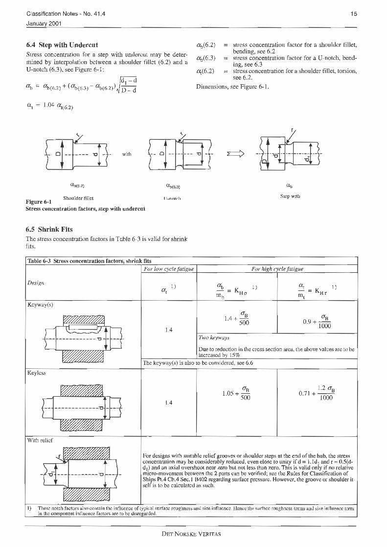
6.4 Step with Undercut
15
Stress concentration for a step with undercut may be determined by interpolation between a shoulder fillet (6.2) and a U-notch (6.3), sec Figure 6-1:
<Xj.,(6.2)
ab(6.3)
Q((6.2)
= stress concentration facLor for a shoulder fillet, bending, see 6.2
= stress concentration factor for a U-notch, bending, see 6.3
= stress concentration for a shoulder fillet, torsion, see 6.2.
a b = ~(6.2) + ( lXi>(G.3) - lXi>(6.2l) £ Dimensions, see Figure 6- I.
ex., 1.04 at(G.2)
- · 0 -- ---- 'O ·- - with Cl!-- - --- " - -
<lt.(6.2) <Xi>(6.3)
11-nntch S1ep with Shoulder fillet
Figure 6-1 Stress concentration factors, step with undercut
6.5 Shrink Fits The stress concentration factors in Table 6-3 is valid for shrink fi ts.
Table 6-3 Stre!is concentration factors, $hrink fits
Kcyway(s)
Key less
With relief
For low cyclefatiRue
1) a,
1.4
For high cyclefmigue
Two key.-vays
Oue to reduction in Lhe cross section area, the above values arc to be increased by 15%
The kcyway(s) is also to be considered, see 6.6
1.4
1.2 a0 0.71 + 1000
For designs with suitable relief grooves or shoulder steps at the end or the hub, Lhe stress concentration may be considerably reduced, even close to unity if d = I. Id 1 and r = 0.5(dd 1) and an axial overshoot near 1..ero but noL lcss than zero. This is valid only if no relative micro-movemcnl between the 2 parts can be verified; sec the Rules for Classification of Ships PL.4 Ch.4 Sec. I '6402 regarding surface pressure. However, the groove or shoulder itself is lo be calculated as such.
1) These notch factors also contain the influence of lypical surface roughness and size influence. Hence the surface roughness tenns and size influence ccrm in the com oncnt i nnuence factors are to be disrc nrded.
DET NORS.K.E VERITAS

16
For hollow shafts with a relatively large inner diameter the notch factors are higher. However, this can he compensated by means of an expansion sleeve in the inner bore.
Table 6·4 Stress concentration factors, kcyways Design Semicircular ends
6.6 Keyways
Classification Notes - No. 41 .4
January 2001
The stress concentration factors in the bollom of a keyway is given in Table 6-4.
For l-0w and high cycle fatigue
<Xi., = 1.4 + 0.015 s! r
r (for d < 0.006 Lhii:; formula gives too high stre:>:; concentration)
d a1 = 2.1 + 0.012 -r
(for ~ < 0.0075 this formula gives too high stress concentration)
Sled runner ends
~ = '1.4
d at = 2. l + 0.012 -
r
(for J < 0.0075 this formula gives too high stress concentration)
For hollow shafts with inner diameter greater than 0.5 d, the increase of nominal stresses due lo the keyway(s) has to be considered.
Note that these stress concentration factors are to be used together with the real nominal stresses applied at the end of the kcyway, see Figure 6-2, i.e. the influence of huh stiffening in bending and torque transmission due to friction may be considered.
The shrink fit between shaft and hub is also to be considered, see 6.5.
Location of real nominal stresses for keyways
Figure 6·2 l<.:yway inside hub
Der NORSKE VERITAS
#/.,i· ,, // ....
;-·· . / ,. .... · / ..... ··· ... ·"·" / ,/ // / / _....· / / /
,,/ //// /_,./"/// ........ ,,/ 11' • ... ••• /-.... ·" ...... ~ /" ,/' / ,. / ,(, .. / /'' ..... . ·"
,,,, ·' .. "'
,. ' I _, "'/' / / .. .•l ,/ / ;'+' ,,.. ./• / , I' I
./ / ··"/" ,/ / / / ,//" I' / / ,. // / / /
//.'°,/ /'// // t' •• • •• / .I // / _,,,·· .,,,,. ,,~" .. .I.... ./ ,,. / .
/'/ ,/ /

Classification Notes - No. 41. 4
January 2001
17
6.7 Radial Holes For a radial hole with diameter db< 0.2 d and a central bore ~ < 0 .5 d ( i.e. 2 outlet holes diametrically oppuscd), the stress
concentration factors at the surface in the radial hole outlets are given in Table 6-5.
Table 6-5 Stress concetration factors, radial holes
De.l"ign For tow and high cycle fmigue
d
dh (dh)2 a1 = 2.3 -3.4 d + 17.5 d
As an approximation the same fonnulae may be u~ if only one oullet. With intcn;ecting eccentric axial bore Multiply the above formulae with:
kcc - ecce ntricity ratio = d
d
- For kcc > 0,85 the stress concentralion will be bpecia1Jy considered.
The notch radius to be used in the formulae for component influence factors in 4.4 is the radial bole radius = 0.5 ~ and the nominal stress is based on the full secti<m.
high torsional vibrations, such as direct coupled plants, no sharp edges are acceptable.
Important Note: 6.8 Longitudinal Slot The stress concentration in the intersection itself can be much higher and is subject lo special consideration. J-1or plants with
For longitudinal slots, the stress concentration factor is given in Table 6-6.
T.tble 6-<i Stress concetration factors, longitudinal slots
Design
where:
For low and high cydefatigue
l- c a1 = 2.3 + 0.4 r.:=
...;tr
r = ~ for semicircular ends 2
The formula is valid for:
0.2 d s; d1 $ 0.85 d 0.05 d $ c $ 0.2 d r s; e for outlets each 180° anrl for outlets each 120°.
The radius to be used in the fonnulae for component influence factors in 4.4 is e/2.
DET NORSKE VcRlTAS

18
6.9 Splines The stress concentration factors I} given in Table 6-7 may be applied.
Table 6-7 Stress concet..-ation factors, splines
Design
Involute splines:
Non-involute splines:
Parallell splines
Trape7.0dial (serra1cJ) splines
For low cycle fat igue
1.15
l) Note thnl lhe nominal stresses are based on the n>ot diameter of the splines.
Classification Notes - No. 41 .4
January 2001
For high cycle fatigue
iXi, = K 2 ) --Ho
..!!L O.Y6 + 1000 ..s_
0 ·92 + 1500
Higher not<.:h factors apply (LO%)
2) These nolch factors also cootain the influence of typical surface roughness and size innuence. Hence the ~urface roughness t1:1111s nnd size influence term in the com ncnt influence factors are to be disre arded.
Note that higher notch factors apply if the hub i.'l very rigid, i.e. the torque transmission is concentrated at the hub edge, see Figure 6-3.
- - -- -- -_t:====:::L Figure6-3 Spline connection with very rigid huh
Dl:::T NORSKE VERlTt\S

Classification Notes · No. 41.4
January 2001
6.10 Square Groove (Cil'clip) The i>tress concentration factors given in Table 6-8 may be applied.
Table 6-8 Stress concetration factors, square grove (circlip) Design For low cycle
fatigue
--~ ---~----J_J 3.0
For high cycle fatigue
0.4724(D - d) I 1.03+ - (0.51 4 +0.00152ay)
r + 2.9 · 10
l .48 +i l __ 0._10_1_3"""-(D_-~d)'---(0.514 +0.00152ay)
r+ 10
- If calculated value of ~ > 4 , use 4 and if mb
at - > 2.5, use 2.5. mt
- If 02~ d < 1.4 , multiply the above formulae with: 0.94( D ~ ~-0.2
DET NORSKE VRRJTAS
19

20
Appendix A Examples The examples presented in this Appendix arc solely meant for demonstration of the calculation meLho<l an<l are not to be used
r Iii 'I'
Classification Notes - No. 41 .4
January 2001
for dimcn.~ioning purposes as fictitious loads and dimensions arc used.
II ,,, ?::'?, -'~ m n ..__filL_.1~~~~~~~~-"-~~~~--'-~~~~~-swll'--~~~-"---- !!'I~'~~---'
Figure A-1 Geared CP-propeller plant
A.1 Calculation example 1: Propeller shaft in a geared, controllable pitch plant with no ICE-class The shafL arrangement is shown in Figure A- 1.
A.1.1 ln way of propeller flange
Ji'i~ureA-2
Propeller flange fillet
Relevant loads:
Torque at maximum continuous power, T0 = 62 kNm Application factors , repetitive cyclic torques (taken from the torsional vibration cakulations): ln normal operation c<m<lition, K Anorm. = 1.2 In misfiring condition, KAmisf. = 1.3 Rotating bending moment, Mh = 24.8 kNm (taken from the shaft alignment calculations including the bending moment due to thrust eccentricity or as a simple and conservative estimation by 0.4T0)
No significant clutching-in shock loads
Relevam dimensions:
Outer diamcler, <l = 220 mm Inner diameter, di = I 00 mm Flange diameter, D = 475 mm Radius of flange fillet, r = 30 mm Flange thickness, t = 65 mm Surface roughncs.~ in flange fillet, Ra= 0.8 µm, i.e. Ry""' 4.8 µm
Relevant material data:
EN 10083-1: C45E +N ( 1.11 91) with the following mechanical properties for representative lest ~ieces l): Ultimate tensile strength, Oh ~ 560 N/mrn Yield strength, ay ~ 275 N/mm2.
I ) See the Rules for Classification of Ship~ Pt.2 Ch.2 Sec.5.
Calculations:
The low cycle criterion (sec 3.2):
Cf.
'<max = 'to KA ~~ L
Nominal torsional stress at maximum continuous power (see 3.3):
-ro = 6
16 · 220 · 62 · IO N/ mm2= 30.98 N / nun2
Jt(2204
- 1004
)
Application factor (maximum KA to be used in this criterion, sec 3.3): KAmisf. = 1.3 Yield strength: ay = 275 N/mm2
Safety fador (see the Rules for Classification of Ships Pt.4 Ch.4 Sec. l B205): S = 1.4 {January 2001) Geometrical stress concentration factor, torsion (see 6.2): a;= 1.33 Component influence factor for low cycle fatigue (see 3.5):
KL = 1 + (l.33 -1)~~~ + I0-4
(560-200)Log4.8= 1.13
DET NORSKE VERITAS

Classification Notes - No. 41.4
January 2001
Consequently:
1.3 · 30.98 N/ rnm2 $
275 N/mm2
2. 1.4 . 1.13
~ 40 . 3 N/rnrn
2 $ 86.9 N/mm
2
or actual safety factor, S = 3.0
Conclusion: Criterion fulfilled.
The high cycle criterion (sec 4.2):
('v)2 +(6b)2 ::;;..!... -rf <Jr. s2
Nominal vibratory torsional stress for continuous operation (see 4.2): !\. = (KAnorm. - 1)1{} = ( 1.2 - 1) 30.98 N/111m2 = 6.20 NI mm2
Nominal reversed bending stress amplitude:
6
6 b = 32 · 220 · 24.8 · 10 N/rnm2 = 24.8 N/mm2
JZ"(2204
- 1004
)
Geometrical stress concentration factors (see 6.2): Torsion: ~ = 1.33 Bending: o:i, = 1.61 Notch sensitivity coefficients (see 4.4. l):
Torsion: mr = I + (2;~ - O.os) ~ = 1.03
B ending: mb = I + (2;~ - O.os) Jlo = 1.04
Component influence factors for high cycle fatigue (see 4.4):
Torsion: Kn-r = ~:~; + 0.01 J30 + 3 · 10-4
(560 - 200)Iog4.8= 1.42
Bending: KHa = ~ :~ + 0.01J30+ 4 · 10-4 (560- 200)1o~4.8= l.70
- High cycle fatigue strengths (see 4.3):
T . . . _ 0.24 · 275 + 42 - 0.15 · 30.98 72_78 N/mm2 or s1on. 'tr -1 _42
Be cl'ng· O'. _ 0.4 · 275 + 70 - 0.4 · 30.98 98.59 N/mm2 n I . f - 1.70
Safety factor (see the Rules for Classification of ships, PL4 Ch.4 Sec. I B205): S = 1.6 (Jan. 2001) Consequently:
( 6.20 12 +(24.78)2 = 0.07 ~(~'2= 0.39 72.78J 98.59 L6J
or actual safety facLor, S = 3.8
Conclusion: Acceptable, and the dimensions could be reduced provided that the stern tube bearing pressure remains within the acceptable rule limits in all operating conditions (full and idle speed respectively).
The transient vibmtion criterion (see 5):
21
Not applicable since lhis is a geared plant with no barred speed range.
A.1.2 In way ofshaft coupling:
Figure A-3 Propeller shaft end at shrink fit coupling
Relevant loads:
Torque at maximum continuous power:, T0 = 62 kNm Application factors, repetitive cyclic torques (taken from the torsional vibration calculations): [n normal operation condition, KAnonn. = 1.2 In misfiring condition, KAmisf. = 1.3 Negligible rotating bending moment (confirmed by shaft alignment analysis) No significant clutching-in shock loads
Relevant dimensions:
Outer diameter, d :::: 200 mm - Inner diameter, di = 93 mm - Surface roughness, Ra = I .6 µm, i.e. Ry "" 9.6 µm
Relevant material data:
EN I 0083- 1: C45E +N (1.1 191 ) with the following mechanical properties for representative test pieces1>: Ultimate tensile strength, o-8 ~ 560 N/mm2 Yield strength, O'y ~ 275 N/mm2.
1) Sec chc Rules for CJa.~8ific:a1ion of Ships Pt.2 Ch.2 Sec.5
Calculations:
The low cycle criterion (sec 3.2):
_!!y_ '"ma;ic; = "to KA s; 2 S K
L
Nominal torsional sti·c,qs at maximum continuous power (see 3.3):
6 'E"u = 16. 200. 62. JO N/mm2 = 41.41 N/mm2
1t(2004
- 934
)
ApplicaLion factor (maximum KA to be used in this criterion, see 3.3): KAmisf. = 1.3 Yield strength: ay = 275 N/mm2
Safety factor (sec the Rules for Classification of Ships Pt.4 Ch.4 Sec. I 8205): S = 1.4 (January 2001)
DRT NORSKE VERITAS

22
Geometrical stress concentration factor, torsion (see 6.5): Qi=l.4 Component influence factor for low cycle fatigue (see 3.5):
275 KL :::: I +(1.4 - 1)
900 = 1.12
Consequently:
1".l.ii1 Jl 1 l\T/mm2 < 275 l\.l/,._,~ 2 . ... . . . . •• ........ - 2. 1.4. 1.2 . ....... .
n "/. 2
53.8 N/mm $; 87.7 N/mm
or actual safety factor, S = 2.3
Conclu.~ion: Criterion fulfilled.
The high cycle criterion (see 4.2):
(rv) (ub) 1 - + - <-Tr O"f - S2
Nominal vibratory torsional slJ·ess for continuous operation (see 4.2): rv =(KAnorm.- l )t"o= (l.2 - 1)41.41N/mm2 =8.28 N/mm2 Geometrical stress concentration factor, tors.ion (see 6.5):
Figure A-4
at = 0.71 + 1.2 . 560 = 1.38 mt 1000
I - --___ _ .J
Direct coupled CP-propeller plant
A.2 Calculation example 2: Oil dis tribution shaft in a direct coupled, controllable pitch plant with no ICE-class: T he shaft arrangement is shown in Figure A-4.
Classification Notes - No. 41.4
January 2001
This notch factor contains also I.he influence of the surface roughness and size influence. Hence, the component int1uencc factor for high cycle torsional fatigue (see 4.4): KHr= 1.38 High cycle torsional fatigue strength (see 4.3):
T . . _0.24 ·275+42 - 0.15·4!.41
ors1011. "tr - 1.38
= 73.76 N/mm2
(a:) 2 "" 0 , since rotating bending moment ic; negligible at O"r
this section of the shaft Safety factor (sec the Rules for Classification of Ships Pt.4 C h.4 Sec.I B205): S = 1.6 (January 2001 )
Consequently:
for acll.lal safety factor, S = 8.8
Conclusion: Acceptable, and it means that the shaft dimensions may be reduced, provided that acceptable friction torque transmission through the :>hrink fit coupling is maintained.
T he transient vibration criterion (see 5):
Not. applicable sin(;c this i::; a geared plant with no barred speed ranges.
(~
. 1r
Main engine: 6 cylinder MAN R& W 6S42MC rated to 5300 kW at 120 r.p .m.
Control system: Only pitch control, i.c engine running al C(m
stant speed. No combinator mode.
DRT NORSKE Yl:iRITAS

Classification Notes • No. 41.4
January 2001
A.2.1 In way of slot in the oil distribution shaft:
(
Figure A-5 Design of slot in O.D.-shaft
Relevant load.~:
SEEN FROMX
~ I I
I ly
\+--
370
Ra 1 .
R:±t
Torque at maximum continuous power, T 0 = 421.8 kNm at no= 120 r.p.m.
50 r::; I .... 'f :::
45
~ 40 " g
35
~ 30
25
20
15
i
I I
I 10
5 ~
~ ,,,....
. v 0
20 <O 60
FigureA-6 Torsional vibration calculations in normal condition with full pitch
\ \
23
SECJ]ON Y .y
Negligible rotating bending moment (confirmed by shaft alignment analysis) Calculated steady state torsional vibrations (full pitch) according to Figure A-6.
MCR
\. ~ I../" ~ :syn1 ~
~ -......__..;
es is
- - ~ ~
80 10() 120 140
Et-<;!~ SPEEO !RPM)
DET NORSKF. VERJT AS

24
In this case the calculated torsional vibration level for zero pil1.:h reaches approximately the same level as for full pitch, see Figure A-9. The reason for this is that both the engine excitation and propeller damping is lower for zero pitch than for full pitch. The 6th order resonance speed is 72 r.p.m. (1. mode nat-
50
'" I .... z 45 ..! =: tll ~ "'
40
~ 35
~ 30
25
20
Ji
~~ 15
p 10
5 ':ir- i---
.. -0
20 40 60
Figure A-7
l't
fl
Classification Notes • No. 41 .4
January 2001
ural frequency = 433.6 vibr/min). In misfiring condition, the torsional vibration stresses due to the 6th order excitation will be lower than for normal condition, due to one cylinder with no ignition, see Figure A-7.
MCR
\~
\ '-V'- _/ -~ A /
v ·---' ../ _-:>-
_ _/ -:x :-4---- -80 100 120 140
ENG [1£ SPf.EO (RPM)
Torsional vibration calculations in misfiring condition with reduced pitch corresponding to 3500 kW at 120 r.p.m.
Relevant dimensions:
Numher of slots: 3 (each 120°) Outer diameter, d = 520 mm Inner diameter, di = 402 mm Length of slot, 1 = 370 mm Width of slot, e = 60 mm Edge radius of slot, re= 21 mm Surface roughness at the edge of the slot, Ra= 1.6 µm, i.e. Ry"' 9.6 µrn
Relevant material data:
EN 10083-1: 42CrMo4 +QT (1.7225) with the following mechanical properties as specified by the designer for representative test pieces1): Ultimate tensile strength, OB ~ 750 N/mm2
Yield strength, ay ~ 450 N/mm2
I) See the Rules for Classification of Ships Pl.2 Ch.2 Sec.5.
Calculations:
The low cycle criterion (see 3.2):
Nominal torsional stress at maximum continuous power (see 3.3):
t'o = 16 · 520 · 421.8 · 106 = 23 _77 N/mm2
1t(5204
- 4024
)
Maximum value of ( r + rv) in the entire speed range (see '.U):
In this case there are three potential maximwn values of (r+ iy):
a) Running with full pitch al n0 = 120 r.p.m. in no1mal condition:
Nominal torsional stJess: -r0 = 23.77 N/mm2 and vibratory torsional stress (see Figure A-6): 1V = 8.6 N/nun2. Thus, in this case ( i-+ t'v) = 32. 4 N/mm2.
b) Running with full pitch at n0 = 120 r.p.m in misfiring condition (one cylinder without combustion):
Since the thermal load on the remaining 5 cylinders will be too high at 120 r.p.m, the power has to be reduced to 3500 kW. Nominal torsional stress at 120 r.p.m is then:
3500 2 2 •omisr. =
5300 · 23.77 N/mm = 15.70 N/mm
Vibratory torsional stress at 120 r.p.m in misfiring condition is according to the torsional vibration calculations: 'fv misf. =
211.7 N/mm2. Thus, in this case ('r+
'fv) = 27.4 N/mm .
c) Running (accidently*) al 61h order resonance speed= 72 r.p.m with 0-pitch:
DET NORSKE VERITAS
Classification Notes - No. 41.4
January 2001
Nominal torsional stress at 72 r.p.m with 0-pileh is assumed to be approximately 15% of the nominal lorsional stress with full pitch:
(72_12 2 2
'X'nRPM = 0.15 l2o) 23.77 N/mm = 1.28 N/mm
Vibratory torsional stress at 72 r.p.m with 0-pileh is according to the torsional vibration calculations (see Fig.A-9):
2 'tv?2PRM = 40.0 N/mm .
Thus, in this case ('X'+ iy) = 41.3 N/mm2.
* Accidently, since running steady at 72 r.p.m is not relevant as the high cycle criterion below concludes with a ba.tTcd speed range around 72 r.p.m.
The maximum torsional stress occurs in case c):
2 Cr+ r.) = ('X'+ r. )72 = 41.3 N/mm v Illa)( v r.p.m
Yield strength: 2 ay = 450 N/mm
Satety factor (see the Rules for Classification of Ships Pt.4 Ch.4 Sec.l B205): S = 1.4 (January 2001) Geometrical stress concentration factor, torsion (based on FEM-calculations since the empirical formula in 6.8 is not valid due to 3 slots and d/d > 0.5): a. =4.22 Component intluence factor for low cycle fatigue (see 3.5):
450 -4 KL = 1 + (4.22 -1)
900 + 10 (750 -200)1og9.6 = 2.66
Consequently: 2 450 2 2
41.3 N/mm ~ 2
• 1.4
. 2
.66
N/mm = 60.4 N/mm
50 N'
~ ?:
45
... Ul
!!! "'
40
~ 35
~ 30
25
j
I I
20
15
~ ~ -
ID
5
Fi2ure A-8 ° -
11
0
25
or actual safety factor, S = 2.0
Conclusion: Criterion fulfilled.
The high cycle criterion (see 4.2):
(t'vJ2 +(O'h)2 ~~ -rr <Jr s
Notch sensitivity coefficient for high cycle torsional fatigue (see 4.4.1 ):
m1 = 1 + (465°0 -0.05) ~ = 1.02
Component influence factor for high cycle torsional fatigue (see 4.4):
KH = 4·22 + 0.01J36+3 · I0-4(750 - 200)log9.6 = 4.35
'i 1.02 - High cycle torsional fatigue strength (see 4.3):
2 0.24. 450. 42-0.15 · 0.15 ·A. · 23.77 N/mm2
t'f = 4.35
= 34.48-0.12A.2
N/mm2
A. is the speed ratio = .!!.. no
(Oj,J 2
"' o since rotating bending moment is negligible at O'f
this section of the shaft Safety factor (see the Rules for Classification of Ships Pt.4 Ch.4 Sec. I B205): S = 1.6 (January 2001)
Consequently:
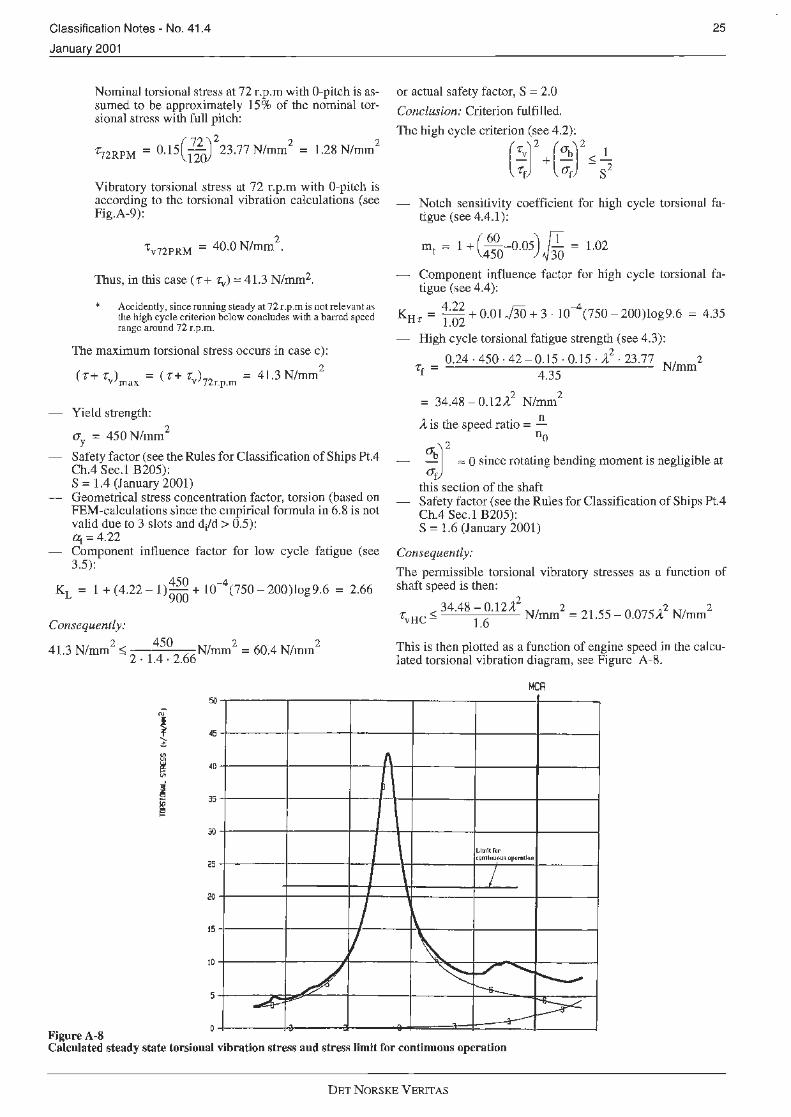
The permissible torsional vibratory stresses as a function of shaft speed is then:
2 < 34.48 - O.l2 ..t NI 2 = 2·1 55 - 0 075 12 N/ 2
t'vHC - 1.6 mm . . - /I. mm
This is then plotted as a function of engine speed jn the calculated torsional vibration diagram, see Figure A-8.
MCR
L.ltnitror contl11uAu~ 01ltrtll4'ld
\ I 1
\
\. ~ l-/ ""- r-.....
r-s.__ -~ ~
Calculated steady state torsional vibration stress and stress limit for continuous operation
DRT NORSKE VERIT AS

26
Conclusion:
The calculated stresses are higher than the allowable stresses for continuous operation around the 6th order resonance at 72 r.p.m. This means that a barred speed range ha:-; to be introduced from 66 to 78 r.p.m. In order to take into account some speed hunting and the inaccuracies of the calculations and engine lachometer, the barred speed range should be ext.ended some r.p.m (- 2%). In this case the barred speed range should be set to 64 - 80 r.p.m. However, this is to be finally confinned by torsional vibration measurements on board during the sea trials.
The transient vibration criterion (sec 5):
0.4 log(-rvl.~ 0.4 log( tvHC)
(3 . 106] -rvH (Ne) 1vLC
TvT:::;; TvHC ~ = TvLC l04
Permissible high cycle torsional vibration stress, 'l"vHC• as calculated above but with a satety factor of 1.5:
TvHC = 34.4
8 ~~· 12A.2
N/mm2 = 23.0- 0.08 A.2
N/mn/
50
"' i .... 'f 45 ~ Ill ~ Ul
40 _J .. ~ ~
35
3()
25
20
A. is the speed ralio = .!!.. no
Classification Notes - No. 41.4
January 2001
Accumulated number ofload cycles when passing through the barred speed range, Ne is assumed to be less than 105
for this plant since the passage is with zero pitch. Permissible low cycle torsional vibratory stress, -ZVLC• as calculated above:
2 2 -rvLC = 60.4- 0.15 · 4 · 23.77 N/mm
= 60.4 - 3.57 .A.2 N/w.m
2
Consequently:
The permissible torsional vibratory strcs.-;cs in transient condition as a function of shaft speed is then:
0.4 log( 60.4 - 3.57 A.:) •vT:::;;(23.0-0.08 ,1,2)30 23
·0-0.08A N/mm2
This is then plotted as a function of engine .speed in the calculated torsional vibration diagram:, see Figure A-9.
MCR
f'mtar01' Ctundc111
/"p1:rJll101t
J
I \ 15
10
-/ ~ fl, ~- ~- - .~ -- ~
5
-. 0
20 40 60 eo 100 120 140
Et4Gll'E SPEED IAPHl
Figure A-9 Calculated steady state torsional vibration stress with 0-pitch and stress limit for transient operation
Conclusion:
If we compare the stress limit for transient operation with the calculated steady state stress, we see from Fig.9 that the limit is just reached at 72 r.p.m. However, when quickly pa.-;sing the harrcd speed range with 0-pitch, the stresses will not have sufficient time lo build up to the calculated steady state level. Also the expected number of cycles of significant load may be lower than the assumed 1 os when quickly passing through the barred
speed range. This is to be verified by measurements on board dming sea trials or be based on experience with similar plants.
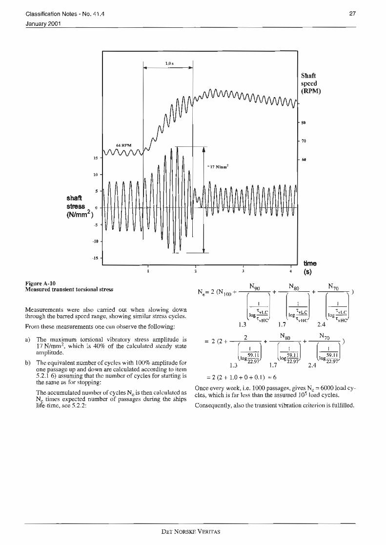
The measured shaft stresses converted to the O.D. shaft during the sea trials when passing quickly through the barred speed range with zero pitch arc shown on Figure A- I 0. The engine was taken up to 64 r.p.m with zero pitch and kept there some seconds. Then the engine was hrought as quickly as po~sihle with zero pitch through the ba1Ted speed range to 90 r.p.m, sec Figure A-JO.
DET NORSKE VERITAS
Classification Notes· No. 41.4
Januar 2001
15
10
s shaft
1,0s
stress o -u-1-+-1_._,-++-1-+++++++--1-H++~ (N/mm2 )
-5
-10
-15
Figure A-10 Measured transient torsional stress
Measurements were also carried out when slowing down through the barred speed range, showing similar stress cycles.
From these measurements one can observe the following:
a) The maximum torsional vibratory stress amplitude is 17 N/mm2, which is 40% of the calculated steady state amplitude.
b) The equivalent number of cycles with l 00% amplitude for one passage up and down are calculated according to item 5.2.l 6) assuming that the number of cycles for starting is the same us for stopping:
The accumulated number of cycles Ne is then calculated as J':'i: ti!-'fies expected. number of passages during the ships hte-tune, see 5.2.2.
+J7 N/01m2
2 3 4
= 2 (2 + 1.0 + 0 + 0.1) "' 6
Shaft speed (RPM)
80
70
time (s)
27
Once every week, i.e. 1000 passages, gives Ne = 6000 load cycles, which is far less than the assumed J 05 load cycles.
Consequently, also the transient vibration criterion is fulfilled.
DET NORSKE V ER IT AS