Exadaktylos 2002-Aclosed-Form Elastic Solution for Stresses and Displacements Around Tunnel

196 TECHNICAL JOURNAL 12, 4(2018), 196-203
ISSN 1846-6168 (Print), ISSN 1848-5588 (Online) Original scientific paper https://doi.org/10.31803/tg-20180824073309
CALCULATION OF DISPLACEMENTS AND STRESSES IN CYLINDRICAL SHELLS BY THE BOUNDARY ELEMENTS METHOD
Aleksej ANISKIN, Viktor F. OROBEY, Leonid V. KOLOMIETS, Aleksandr M. LYMARENKO
Abstract: The application of the boundary element method to the calculation of a closed circular cylindrical shell of step-constant thickness, loaded over the entire surface by a uniform normal pressure, is described. The numerical example is considered. The results of the calculation are compared by two numerical methods – boundary and finite elements.
Keywords: cylindrical shells of piecewise constant rigidity; finite element method; MATLAB; non-conservative problems of stability; numerical-analytical boundary element method; rod system; stress-strain state
1 INTRODUCTION
The majority of the problems of construction mechanics associated with the study of the stress-strain state (SSS) of designs and their elements are reduced, as a rule, to one or several differential equations. Accurate solutions of these equations, namely the solutions in a closed form, cannot al-ways be obtained. In this regard, for the solving of many practical problems, approximate methods of research are used.
Presently, the most developed numerical method is the finite element method (FEM). The search for alternative ap-proaches had led to the emergence of a new method, or ra-ther, to the emergence of the boundary element method (BEM). Here, the whole area under consideration is not sub-jected to discretization, as opposed to the finite element method, but only its boundary. Considerable numbers of works are devoted to this direction in the field of structural mechanics. However, many problems remain unresolved. One of these problems is the calculation of shells.
2 ANALYSIS OF RECENT RESEARCH AND PUBLICATIONS
A great variety of engineering tasks in construction requires the attraction of effective methods for their calculation. Since researchers are not always satisfied with the results of FEM, it is extremely necessary to apply accurate and perfect methods for the calculation and analysis of engineering structures, in particular of cylindrical shells.
The literature on the research of cylindrical shells is very voluminous. However, there is no research where a modern numerical-analytical variant is applied [1-5]. Basically, the numerical-analytical version of BEM is developed for rod and plate systems [6-11].
At the same time, with insignificant resources (memory and speed), BEM allows engineers to obtain very accurate values of the stress-strain state of various engineering constructions. In this connection, the application and obtaining of mathematical models for various variants of BEM is an actual problem in calculations, modeling and designing of existing engineering constructions.
3 THE PURPOSE OF THE WORK
The purpose of this research is the construction of mathematical models of the state of cylindrical shells of piecewise constant rigidity that are suitable for the application of the numerical-analytical variant of BEM. Calculations of the stress-strain state of the cylindrical shells of BEM and FEM (ANSYS) are performed and their results are compared (MATLAB).
4 MAIN PURPOSE OF THE ARTICLE
Let us consider the bending of the closed circular cylin-drical shell of step-constant thickness, loaded over the entire surface by the uniform normal pressure intensity p (Fig. 1).
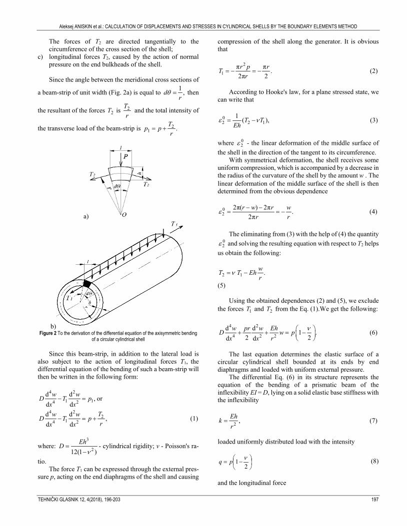
In view of the symmetry of the load p relative to the shell axis, the deformation of the latter will also be symmetric. The bending of such a shell can be characterized by the bending of a beam-strip of unit width separated from the shell under consideration by two meridional planes (Fig. 2).
Figure 1 Closed circular cylindrical shell that is loaded with comprehensive exter-nal evenly distributed pressure
In view of the symmetry of the load p with respect to the shell axis, the deformation of the latter will also be symmet-ric. The bending of such a shell can be characterized by the bending of a beam-strip of unit width, separated from the shell under consideration by two meridional planes (Fig. 2).
The following will act on the beam-strip: a) the transverse load p uniformly distributed along the
length; b) T2 forces applied to the lateral faces of the beam-strip and
characterizing the effect of the cut off part of the shell.
Aleksej ANISKIN et al.: CALCULATION OF DISPLACEMENTS AND STRESSES IN CYLINDRICAL SHELLS BY THE BOUNDARY ELEMENTS METHOD
TEHNIČKI GLASNIK 12, 4(2018), 196-203 197
The forces of T2 are directed tangentially to the circumference of the cross section of the shell;
c) longitudinal forces T2, caused by the action of normal pressure on the end bulkheads of the shell.
Since the angle between the meridional cross sections of
a beam-strip of unit width (Fig. 2a) is equal to 1 ,dr
θ = then
the resultant of the forces 2T is r
T2 and the total intensity of
the transverse load of the beam-strip is .21 r
Tpp +=
a)
b) Figure 2 To the derivation of the differential equation of the axisymmetric bending
of a circular cylindrical shell
Since this beam-strip, in addition to the lateral load is also subject to the action of longitudinal forces Т1, the differential equation of the bending of such a beam-strip will then be written in the following form:
4 2
1 14 2d d ,d d
w wD T px x
− = or
4 22
14 2d d ,d d
Tw wD T prx x
− = + (1)
where: 3
212(1 )EhD
ν=
−- cylindrical rigidity; ν - Poisson's ra-
tio. The force Т1 can be expressed through the external pres-
sure р, acting on the end diaphragms of the shell and causing
compression of the shell along the generator. It is obvious that
2
1π π .2π 2r p rT
r= − = − (2)
According to Hooke's law, for a plane stressed state, we
can write that
02 2 1
1 ( ),T TEh
ε ν= − (3)
where 0
2ε - the linear deformation of the middle surface of the shell in the direction of the tangent to its circumference.
With symmetrical deformation, the shell receives some uniform compression, which is accompanied by a decrease in the radius of the curvature of the shell by the amount w . The linear deformation of the middle surface of the shell is then determined from the obvious dependence
02
2π( ) 2π .2π
r w r wr r
ε − −= = − (4)
The eliminating from (3) with the help of (4) the quantity
02ε and solving the resulting equation with respect to T2 helps
us obtain the following:
.12 rwEhTT −=ν
(5)
Using the obtained dependences (2) and (5), we exclude the forces 1T and 2T from the Eq. (1).We get the following:
4 2
4 2 2d d 1 .
2 2d dw pr w EhD w p
x x rν + + = −
(6)
The last equation determines the elastic surface of a
circular cylindrical shell bounded at its ends by end diaphragms and loaded with uniform external pressure.
The differential Eq. (6) in its structure represents the equation of the bending of a prismatic beam of the inflexibility EI = D, lying on a solid elastic base stiffness with the inflexibility
2 ,Ehkr
= (7)
loaded uniformly distributed load with the intensity
−=
21 νpq (8)
and the longitudinal force

Aleksej ANISKIN et al.: CALCULATION OF DISPLACEMENTS AND STRESSES IN CYLINDRICAL SHELLS BY THE BOUNDARY ELEMENTS METHOD
198 TECHNICAL JOURNAL 12, 4(2018), 196-203
.2prT = − (9)
In the notation (7) - (9), equation (6) can be rewritten in the form
.IVEIw Tw kw q′′− + = (10)
The Eq. (10) and possible forms of its general integral are well-known. The form of the general integral is determined by the numerical value of the parameter β:
.2
TEIk
β = (11)
For the shells of greatest practical interest, the parameter
β satisfies the condition 0 < β2 < 1. The general integral of the Eq. (10), or equivalently, of the Eq. (6) can then be writ-ten in the form
1 2
3 4 part
( ) ch cos ch sinsh cos sh sin ,
w x C x x C x xC x x C x x w
δ γ δ γδ γ δ γ= + +
+ + + (12)
where
41 ; 1 ; .4
kEI
δ α β γ α β α= + = − = (13)
As р = const, the particular solution is determined by the
formula
2
part 1 .2
q prwk Eh
ν = = −
(14)
A closed cylindrical shell, bounded at its ends by
transverse diaphragms, cannot perceive large external transverse pressures if the distance between the diaphragms is sufficiently large. Such a shell can lose stability even at a very low value of external pressure.
The most effective means of increasing the stability of cylindrical shells is their reinforcement with annular closed stiffeners.
In connection with this, consider the work on the bending of a closed cylindrical circular uniformly loaded shell, reinforced between transverse diaphragms by equidistant identical annular ribs of the area A (Fig. 3).
Neglecting the influence of the stiffness of the end diaphragms on the work in the middle part of the shell, we can assume that the radial compressions of the shell at a certain distance from the diaphragms will be symmetrical with respect to the plane of the reinforcing ribs. By virtue of this, we can confine ourselves to examining the bending of the shell only within one span.
If we place the origin of coordinates in the middle be-tween the edges (Fig. 4), then, because of the symmetry of
the shell bending relative to the chosen origin in the expres-sion (12), only even terms should be retained, that is, take the form of C2 = C3 = 0.
Figure 3 Scheme of a circular cylindrical shell reinforced with identical equidistant
annular ribs
Figure 4 To the formulation of the boundary conditions of a circular cylindrical shell
reinforced by ribs
Expression (12) takes the form
2
1 4( ) 1 ch cos sh sin .2
prw x C x x C x xEh
ν δ γ δ γ = − + +
(15)
In view of the symmetry of the elastic shell surface
relative to the plane of each of the reinforcing ribs, the angles of the rotation of the shell on the edges will be zero, i.e. with
2lx = ±
d 0.dwx= (16)
The second boundary condition is obtained if we con-
sider the interaction of the shell and the reinforcing edge. When acting on the pressure shell р, the edge is exposed
from the shell side to the action of a uniformly distributed load with the running intensity p1. The linear load p1 is balanced by twice the value of the transverse force in the reference section of a beam-strip of unit width, i.e.
3
1 32
d2 .d lx
wp Dx =
= (17)
The voltage value σp, acting in the cross section of the
edge, can be determined, on the one hand, from the obvious equality
Aleksej ANISKIN et al.: CALCULATION OF DISPLACEMENTS AND STRESSES IN CYLINDRICAL SHELLS BY THE BOUNDARY ELEMENTS METHOD
TEHNIČKI GLASNIK 12, 4(2018), 196-203 199
1 ,pp rA
σ = − (18)
or on the other hand, by the formula
2 .p
lw xE
rσ
= = − (19)
From the comparison of (18) and (19), we obtain
1 22 .
lw xp EA
r
= = − (20)
Eliminating p1 with (20) from (17), we obtain the second
missing boundary condition for determining the integration constants in the expression (15):
2 3
32
2 d .dlx
Dr wwEA x=
= (21)
Substituting the expression for the x from (15) into the
boundary conditions (16) and (21), we obtain two equations, the joint solution of which allows us to determine the unknown C1 and C4:
21 1 2 2 1 2
1 12 1 1 2
22 1 2 1 1 2
4 12 1 1 2
ch sin sh cos2 1 ;2 2 2
ch sin sh cos2 1 ,2 sh2 sin2
u u u u u uprCEh u sh u u sin u
u u u u u uprCEh u u u u
ν ε
ν ε
+ = − − +
− = − − +
(22)
where
1
1 1 2
2 1 21 1 2
2 1 1 2
1 2
1 ;1 ( , )
ch2 cos2( , ) 1 ;sh2 sin2
1 ; 1 ;2 2
0 6425 .
lh A u uA
u uA u uu u u u
l lu u u u
lu ,rh
ε
β
δ γβ β
=+
−= −
+
= = + = = +
=
(23)
With the final expression for w(x), we can determine all
elements of the beam-bending strip and, consequently, the shell elements under consideration bending.
The foregoing solution of the problem takes into account the influence of longitudinal forces on the bending of the shell. However, as numerical calculations show, in most cases, this influence can be neglected. Instead of (10), we should then consider an equation of the form
.IVEIw kw q+ = (24)
As it can be seen from the differential Eq. (24) and the boundary conditions (16) and (21), the approximate solution reduces to solving the problem of the bending of a single-span beam, lying on an elastic foundation loaded with a uniformly distributed load and rigidly embedded at the ends on elastic supports with a compliance coefficient kΠ, equal to
22 .Пrk
EA= (25)
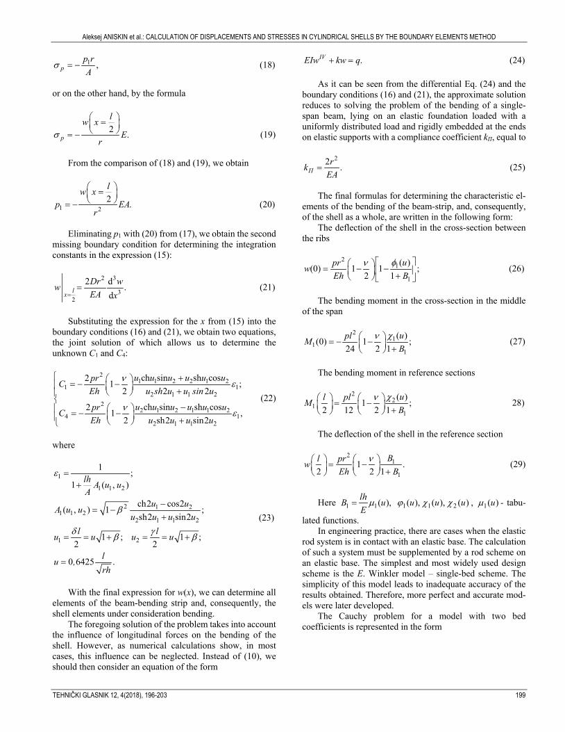
The final formulas for determining the characteristic el-
ements of the bending of the beam-strip, and, consequently, of the shell as a whole, are written in the following form:
The deflection of the shell in the cross-section between the ribs
21
1
( )(0) 1 1 ;2 1
uprwEh B
φν = − − + (26)
The bending moment in the cross-section in the middle
of the span
21
11
( )(0) 1 ;24 2 1
uplMB
χν = − − + (27)
The bending moment in reference sections
2
21
1
( )1 ;2 12 2 1
ul plMB
χν = − + 28)
The deflection of the shell in the reference section
2
1
11 .
2 2 1Bl prw
Eh Bν = − +
(29)
Here 1 1( ),lhB uEµ= )(),(),( 211 uuu χχϕ , )(1 uµ - tabu-
lated functions. In engineering practice, there are cases when the elastic
rod system is in contact with an elastic base. The calculation of such a system must be supplemented by a rod scheme on an elastic base. The simplest and most widely used design scheme is the E. Winkler model – single-bed scheme. The simplicity of this model leads to inadequate accuracy of the results obtained. Therefore, more perfect and accurate mod-els were later developed.
The Cauchy problem for a model with two bed coefficients is represented in the form

Aleksej ANISKIN et al.: CALCULATION OF DISPLACEMENTS AND STRESSES IN CYLINDRICAL SHELLS BY THE BOUNDARY ELEMENTS METHOD
200 TECHNICAL JOURNAL 12, 4(2018), 196-203
2( ) ( ) ( ) 1 ; 2 2
(0); (0) (0);(0) (0) (0);
(0) (0) (0);
2
IY pr EhDv x v x v x pr
v v'M D v T vQ D v T v
prT .
µ
ϕ
′′+ + = −
=′′= − −′′′ ′= − −
= −
(30)
The characteristic equation for the differential Eq. (30) is
a biquadratic:
4 2 22
22
0, ;2
0,2
pr EhD k k k tr
pr EhDt tr
+ + = =
+ + = (31)
which roots
2
2
1 2
2
2
1, 2, 3, 4
42 2
;2
42 2
.2
,
pr pr EhDrt
D
pr pr EhDrk
D
− ± − =
− ± − = ±
(32)
The fundamental orthonormal functions of the task for
all four possible variants of the roots of the characteristic equation are known [1].
Variant 1. Roots are complex (corresponds to low pressures):
1, 2, 3, 4 ,k a ib= ± ± (33) where
4
1 ;
1 ;
;4
2 .2
a
b
kDpr
D k
α β
α β
α
β
= +
= −
=
= −
(34)
Variant 2. Imaginary roots:
1, 2 3, 4; .k ia k ib= ± = ± (35)
This variant of the roots also corresponds to the compres-sion of the shell.
Variant 3. Four valid roots:
1, 2 3, 4; .k a k b= ± = ± (36)
This variant of the roots corresponds to the extension of the shell.
Variant 4. Two real roots and two imaginary roots:
1, 2 3, 4; .k a k ib= ± = ± (37)
This variant of the roots also corresponds to the exten-sion of the shell.
5 RESULTS
As an example, consider a cylindrical shell rigidly clamped along the ends of step-constant rigidity, which is un-der the action of uniform internal pressure (Fig. 5).
The algorithm for calculating of the cylindrical shell is: 1. Break the shell into three modules. 2. We form the matrices of the initial and final parameters
and the load vector, taking into account the boundary conditions, the equilibrium equations and the equations of the compatibility of displacements of the nodes 1 and 2.
An analysis of the matrix *X shows that in the matrix
*А , it is necessary to zero the first and second columns and then introduce compensating elements for transferring the fi-nal parameters from Y to the matrix *X . 3. The equation of the boundary value problem for a cylin-
drical shell by the boundary element method takes the form (38).
4. By solving the system (38) in the MATLAB environ-ment, we obtain numerical and visual parameters of the stress-strain state of the shell.
5. In accordance with the algorithm above, the cylindrical shell of step-constant rigidity is calculated for the action of internal pressure (Fig. 5).

Aleksej ANISKIN et al.: CALCULATION OF DISPLACEMENTS AND STRESSES IN CYLINDRICAL SHELLS BY THE BOUNDARY ELEMENTS METHOD
TEHNIČKI GLASNIK 12, 4(2018), 196-203 201
* =X
;0)0(101 =−vD )( 3
32 lM −
=Y
)0()( 2111
101
−− = vDlvD
=B
- )( 110
11 lB −
;0)0(101 =−ϕD )( 3
32 lQ − )0()( 2111
101
−− = ϕϕ DlD - )( 110
21 lB −
)0(10−M )0()( 211
10 −− = MlM )( 110
31 lB −
)0(10−Q )0()( 211
10 −− = QlQ )( 110
41 lB − )0(21
2−vD )0()( 32
2221
2−− = vDlvD - )( 2
2111 lB −
)0(212
−ϕD )0()( 3222
212
−− = ϕϕ DlD - )( 221
21 lB − )0(21−M )0()( 32
221 −− = MlM )( 2
2131 lB −
)0(21−Q )0()( 322
21 −− = QlQ )( 221
41 lB − )0(32
3−vD 0)( 3
323 =− lvD - )( 3
3211 lB −
)0(323
−ϕD 0)( 332
3 =− lD ϕ - )( 332
21 lB −
)0(32−M )( 332 lM − )( 3
3231 lB −
)0(32−Q )( 332 lQ − )( 3
3241 lB −
(38)
Figure 5 Cylindrical shell of step-constant stiffness
Aleksej ANISKIN et al.: CALCULATION OF DISPLACEMENTS AND STRESSES IN CYLINDRICAL SHELLS BY THE BOUNDARY ELEMENTS METHOD
202 TECHNICAL JOURNAL 12, 4(2018), 196-203
With the indicated shell parameters, the characteristic equation (30) for each section with constant rigidity has, as in the previous problem, complex roots: - On a section with the diameter D1
),0895,00899,0(41 ⋅±±=− ik - On a section with the diameter D2
),0818,00819,0(41 ⋅±±=− ik - On a section with the diameter D3
),0757,00758,0(41 ⋅±±=− ik i.e. where a solution for the fundamental functions and the load vector are used for the Variant 1.
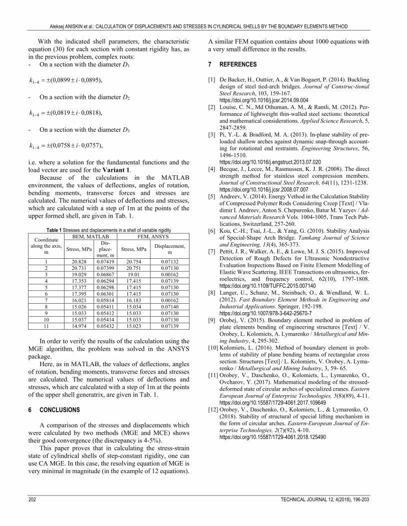
Because of the calculations in the MATLAB environment, the values of deflections, angles of rotation, bending moments, transverse forces and stresses are calculated. The numerical values of deflections and stresses, which are calculated with a step of 1m at the points of the upper formed shell, are given in Tab. 1.
Table 1 Stresses and displacements in a shell of variable rigidity
Coordinate along the axis,
m
BEM, MATLAB FEM, ANSYS
Stress, MPa Dis-
place-ment, m
Stress, MPa Displacement, m
1 20.828 0.07419 20.754 0.07132 2 20.731 0.07399 20.751 0.07130 3 19.029 0.06867 19.01 0.00162 4 17.353 0.06294 17.415 0.07139 5 17.377 0.06298 17.415 0.07130 6 17.395 0.06301 17.415 0.07130 7 16.021 0.05814 16.183 0.00162 8 15.026 0.05411 15.034 0.07140 9 15.033 0.05412 15.033 0.07130 10 15.037 0.05414 15.033 0.07130 11 14.974 0.05432 15.023 0.07139
In order to verify the results of the calculation using the
MGE algorithm, the problem was solved in the ANSYS package.
Here, as in MATLAB, the values of deflections, angles of rotation, bending moments, transverse forces and stresses are calculated. The numerical values of deflections and stresses, which are calculated with a step of 1m at the points of the upper shell generatrix, are given in Tab. 1.
6 CONCLUSIONS
A comparison of the stresses and displacements which were calculated by two methods (MGE and MCE) shows their good convergence (the discrepancy is 4-5%).
This paper proves that in calculating the stress-strain state of cylindrical shells of step-constant rigidity, one can use CA MGE. In this case, the resolving equation of MGE is very minimal in magnitude (in the example of 12 equations).
A similar FEM equation contains about 1000 equations with a very small difference in the results. 7 REFERENCES
[1] De Backer, H., Outtier, A., & Van Bogaert, P. (2014). Buckling
design of steel tied-arch bridges. Journal of Construc-tional Steel Research, 103, 159-167. https://doi.org/10.1016/j.jcsr.2014.09.004
[2] Louise, C. N., Md Othuman, A. M., & Ramli, M. (2012). Per-formance of lightweight thin-walled steel sections: theoretical and mathematical considerations. Applied Science Research, 5, 2847-2859.
[3] Pi, Y.-L. & Bradford, M. A. (2013). In-plane stability of pre-loaded shallow arches against dynamic snap-through account-ing for rotational end restraints. Engineering Structures, 56, 1496-1510. https://doi.org/10.1016/j.engstruct.2013.07.020
[4] Becque, J., Lecce, M., Rasmussen, K. J. R. (2008). The direct strength method for stainless steel compression members. Journal of Constructional Steel Research, 64(11), 1231-1238. https://doi.org/10.1016/j.jcsr.2008.07.007
[5] Andreev, V. (2014). Energy Vethod in the Calculation Stability of Compressed Polymer Rods Considering Creep [Text] / Vla-dimir I. Andreev, Anton S. Chepurenko, Batur M. Yazyev / Ad-vanced Materials Research Vols. 1004-1005, Trans Tech Pub-lications, Switzerland, 257-260.
[6] Kou, C.-H.; Tsai, J.-L., & Yang, G. (2010). Stability Analysis of Special-Shape Arch Bridge. Tamkang Journal of Science and Engineering, 13(4), 365-373.
[7] Pettit, J. R., Walker, A. E., & Lowe, M. J. S. (2015). Improved Detection of Rough Defects for Ultrasonic Nondestructive Evaluation Inspections Based on Finite Element Modelling of Elastic Wave Scattering. IEEE Transactions on ultrasonics, fer-roelectrics, and frequency control, 62(10), 1797-1808. https://doi.org/10.1109/TUFFC.2015.007140
[8] Langer, U., Schanz, M., Steinbach, O., & Wendland, W. L. (2012). Fast Boundary Element Methods in Engineering and Industrial Applications. Springer, 192-198. https://doi.org/10.1007/978-3-642-25670-7
[9] Orobej, V. (2015). Boundary element method in problem of plate elements bending of engineering structures [Text] / V. Orobey, L. Kolomiets, A. Lymarenko / Metallurgical and Min-ing Industry, 4, 295-302.
[10] Kolomiets, L. (2016). Method of boundary element in prob-lems of stability of plane bending beams of rectangular cross section. Structures [Text] / L. Kolomiets, V. Orobey, A. Lyma-renko / Metallurgical and Mining Industry, 3, 59- 65.
[11] Orobey, V., Daschenko, O., Kolomiets, L., Lymarenko, O., Ovcharov, Y. (2017). Mathematical modeling of the stressed-deformed state of circular arches of specialized cranes. Eastern European Journal of Enterprise Technologies, 5(8)(89), 4-11. https://doi.org/10.15587/1729-4061.2017.109649
[12] Orobey, V., Daschenko, O., Kolomiets, L., & Lymarenko, O. (2018). Stability of structural of special lifting mechanism in the form of circular arches. Eastern-European Journal of En-terprise Technologies, 2(7)(92), 4-10. https://doi.org/10.15587/1729-4061.2018.125490

Aleksej ANISKIN et al.: CALCULATION OF DISPLACEMENTS AND STRESSES IN CYLINDRICAL SHELLS BY THE BOUNDARY ELEMENTS METHOD
TEHNIČKI GLASNIK 12, 4(2018), 196-203 203
Authors' contacts: Aleksej ANISKIN, PhD University North, Department of Civil Engineering, Jurja Križanića 31b, 42000 Varaždin, Croatia [email protected] Viktor F. OROBEY, PhD, Professor, Head of the Dept. Department of Dynamics, Strength of Machines and Resistance of Materials, Odesa National Polytechnic University, Shevchenko Avenue 1, Odesa, Ukraine [email protected] Leonid V. KOLOMIETS, PhD, Professor, Rector Odesa State Academy of Technical Regulation and Quality, Kovalska st. 15, Odesa, Ukraine [email protected] Aleksandr M. LYMARENKO, PhD, Associate Professor Department of Dynamics, Strength of Machines and Resistance of Materials, Odesa National Polytechnic University, Shevchenko Avenue 1, Odesa, Ukraine [email protected]