Calculating the Time Constant of an RC Circuit
12
Undergraduate Journal of Mathematical Undergraduate Journal of Mathematical Modeling: One + Two Modeling: One + Two Volume 2 | 2010 Spring Article 3 2010 Calculating the Time Constant of an RC Circuit Calculating the Time Constant of an RC Circuit Sean Dunford University of South Florida Advisors: Arcadii Grinshpan, Mathematics and Statistics Gerald Woods, Physics Problem Suggested By: Gerald Woods Follow this and additional works at: https://digitalcommons.usf.edu/ujmm Part of the Mathematics Commons UJMM is an open access journal, free to authors and readers, and relies on your support: Donate Now Recommended Citation Recommended Citation Dunford, Sean (2010) "Calculating the Time Constant of an RC Circuit," Undergraduate Journal of Mathematical Modeling: One + Two: Vol. 2: Iss. 2, Article 3. DOI: http://dx.doi.org/10.5038/2326-3652.2.2.3 Available at: https://digitalcommons.usf.edu/ujmm/vol2/iss2/3
Transcript of Calculating the Time Constant of an RC Circuit

Undergraduate Journal of Mathematical Undergraduate Journal of Mathematical
Modeling: One + Two Modeling: One + Two
Volume 2 | 2010 Spring Article 3
2010
Calculating the Time Constant of an RC Circuit Calculating the Time Constant of an RC Circuit
Sean Dunford University of South Florida
Advisors:
Arcadii Grinshpan, Mathematics and Statistics
Gerald Woods, Physics
Problem Suggested By: Gerald Woods
Follow this and additional works at: https://digitalcommons.usf.edu/ujmm
Part of the Mathematics Commons
UJMM is an open access journal, free to authors and readers, and relies on your support:
Donate Now
Recommended Citation Recommended Citation Dunford, Sean (2010) "Calculating the Time Constant of an RC Circuit," Undergraduate Journal of Mathematical Modeling: One + Two: Vol. 2: Iss. 2, Article 3. DOI: http://dx.doi.org/10.5038/2326-3652.2.2.3 Available at: https://digitalcommons.usf.edu/ujmm/vol2/iss2/3

Calculating the Time Constant of an RC Circuit Calculating the Time Constant of an RC Circuit
Abstract Abstract In this experiment, a capacitor was charged to its full capacitance then discharged through a resistor. By timing how long it took the capacitor to fully discharge through the resistor, we can determine the RC time constant using calculus.
Keywords Keywords Time Constant, RC circuit, Electronics
Creative Commons License Creative Commons License
This work is licensed under a Creative Commons Attribution-Noncommercial-Share Alike 4.0 License.
This article is available in Undergraduate Journal of Mathematical Modeling: One + Two: https://digitalcommons.usf.edu/ujmm/vol2/iss2/3

2 SEAN DUNFORD
TABLE OF CONTENTS
Problem Statement ................................................................................................................... 3
Motivation ................................................................................................................................... 3
Mathematical Description and Solution Approach .................................................... 3
Discussion ................................................................................................................................... 7
Conclusion and Recommendations ................................................................................... 7
Nomenclature ............................................................................................................................. 8
References ................................................................................................................................... 9
Appendices ............................................................................................................................... 10
Dunford: Calculating the Time Constant of an RC Circuit
Produced by The Berkeley Electronic Press, 2010

CALCULATING THE TIME CONSTANT OF AN RC CIRCUIT 3
PROBLEM STATEMENT
Using calculus, determine the time constant of an RC circuit for a recorded time with an
initial charge on the capacitor of , and a voltage of volts.
MOTIVATION
This project and derivation is designed to acknowledge the value of a circuit RC time
constant. Knowing the time constant of an RC circuit can allow it to be used as a hardware filter.
It can be utilized to only react to certain changes within the circuit. For instance windshield
wiper speed settings in modern cars are controlled by RC circuits. They allow a lower voltage to
reach the windshield wipers which makes them move slower. Electronic instruments, washing
pieces of technology all contain RC circuits.
(Koehler,1)(Sheets. 1)
MATHEMATICAL DESCRIPTION AND SOLUTION APPROACH
After setting up the circuit to match the schematic and picture of circuit, we place a max
charge on the circuit plate that is equal to that of the power supply (30 volts). The capacitance is
supplied by a decade box and is given as (microfarads). The resistance is given by the
DMM resistor as (megaohms). Our resistor is also used to measure voltages at specific
variable times. Charging the capacitor takes less than a second. We can determine the charge and
charges on all the pieces within a loop will always equal zero at any time (Serway,785), i.e.
. (1)
Undergraduate Journal of Mathematical Modeling: One + Two, Vol. 2, Iss. 2 [2010], Art. 3
https://digitalcommons.usf.edu/ujmm/vol2/iss2/3DOI: http://dx.doi.org/10.5038/2326-3652.2.2.3

4 SEAN DUNFORD
The emf of the battery is taken to be volts, the current at some instant is represented by ,
the potential drop across the resistor is , the magnitude of the charge on the capacitor at
some instant is , the potential drop across the capacitor plates is shown as (Serway,
745/767). We can now rewrite (1) as
. (2)
Any time before the capacitor has a charge, and (2) becomes
(3)
Once the capacitor has reached the full voltage of the power supply since charge no longer
flows in the circuit. When this happens, (2) becomes
. (4)
Current is the change in charge over the change in time (Serway,753), i.e.
. (5)
By substituting (5) into (2) we have,
. (6)
and implies that
. (7)
If we integrate both sides, we achieve
which evaluates to
. (8)
If , then and (8) becomes
Dunford: Calculating the Time Constant of an RC Circuit
Produced by The Berkeley Electronic Press, 2010

CALCULATING THE TIME CONSTANT OF AN RC CIRCUIT 5
(9)
and simplifies to
. (10)
Note that we may substitute (10) into (5) to get an equation for current:
. (11)
Our main goal is to determine the exact value of the time constant . At time ,
equation (10) tells us that
. (12)
We can determine the time constant more accurately by considering similar equations for the
discharging process. At time the emf from the battery is present on the plates of the
capacitor. After the battery is disconnected from the circuit, the emf on the plates begins to
dissipate. This discharging equation for is similar to (2) and is given by
(13)
which via (11) reduces to
. (14)
During this discharge process is constant as the battery is disconnected from the circuit. Also,
note that the current switches direction away from the capacitor becoming negative. This
transforms (5) into
. (15)
In light of equation (14) and (15) we still get the same positive current equation as in (11)
. (16)
Undergraduate Journal of Mathematical Modeling: One + Two, Vol. 2, Iss. 2 [2010], Art. 3
https://digitalcommons.usf.edu/ujmm/vol2/iss2/3DOI: http://dx.doi.org/10.5038/2326-3652.2.2.3

6 SEAN DUNFORD
During the discharge process, voltages were recorded at various time intervals (see Table
1.2 in the Appendix). Graphing the voltage versus time yielded an exponentially decaying graph.
To determine the time constant, we must establish a linear relationship ( ) of voltage
and time. If we consider that relationship between charge and voltage
(17)
where is voltage, is charge and is capacitance, (14) becomes
. (18)
By taking the natural logarithm of both sides of (18), we establish a linear relationship between
and time :
. (19)
Using linear regression implemented in Excel (Graph 2.1), we find that
which means
and . (20)
From (18) we know that the voltage is of the initial charge during the charging
process. Since we know the initial value is equal to , the emf of the battery the capacitor
at time will read
volts. (21)
Charging the capacitor and timing how long it took to reach our target value of volts
yielded the experimental value of RC.
Dunford: Calculating the Time Constant of an RC Circuit
Produced by The Berkeley Electronic Press, 2010
CALCULATING THE TIME CONSTANT OF AN RC CIRCUIT 7
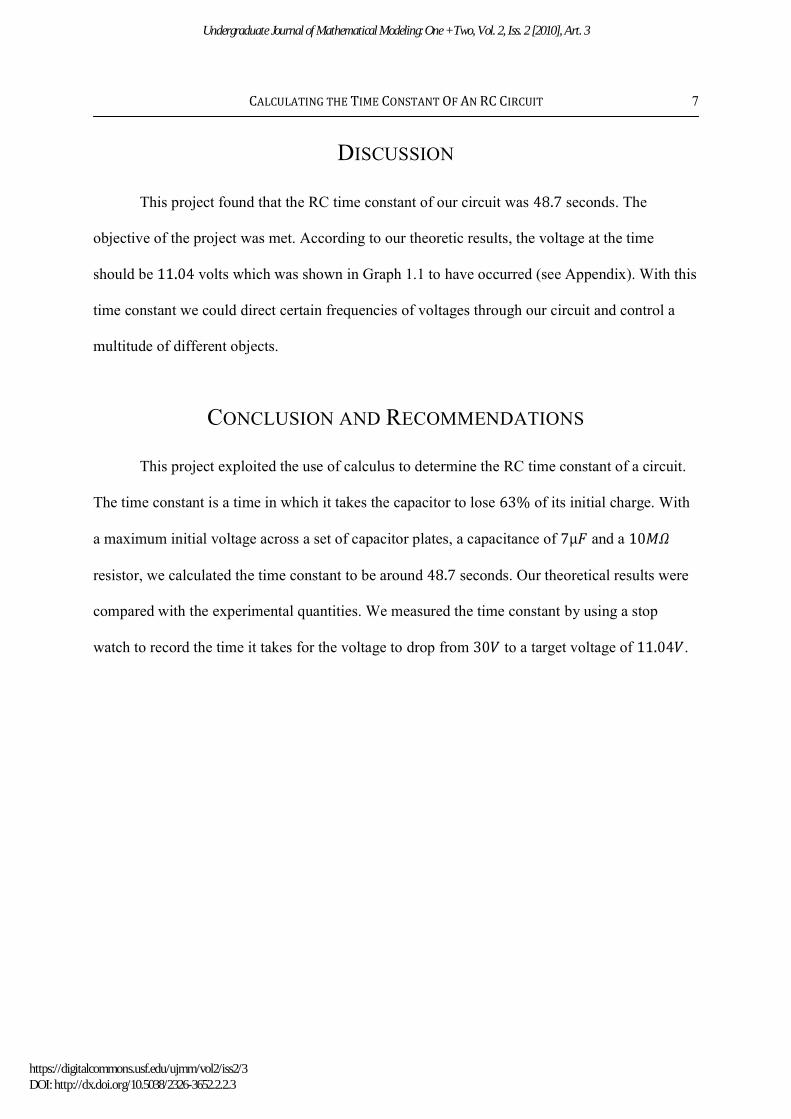
DISCUSSION
This project found that the RC time constant of our circuit was seconds. The
objective of the project was met. According to our theoretic results, the voltage at the time
should be volts which was shown in Graph 1.1 to have occurred (see Appendix). With this
time constant we could direct certain frequencies of voltages through our circuit and control a
multitude of different objects.
CONCLUSION AND RECOMMENDATIONS
This project exploited the use of calculus to determine the RC time constant of a circuit.
The time constant is a time in which it takes the capacitor to lose of its initial charge. With
a maximum initial voltage across a set of capacitor plates, a capacitance of and a
resistor, we calculated the time constant to be around seconds. Our theoretical results were
compared with the experimental quantities. We measured the time constant by using a stop
watch to record the time it takes for the voltage to drop from to a target voltage of .
Undergraduate Journal of Mathematical Modeling: One + Two, Vol. 2, Iss. 2 [2010], Art. 3
https://digitalcommons.usf.edu/ujmm/vol2/iss2/3DOI: http://dx.doi.org/10.5038/2326-3652.2.2.3
8 SEAN DUNFORD
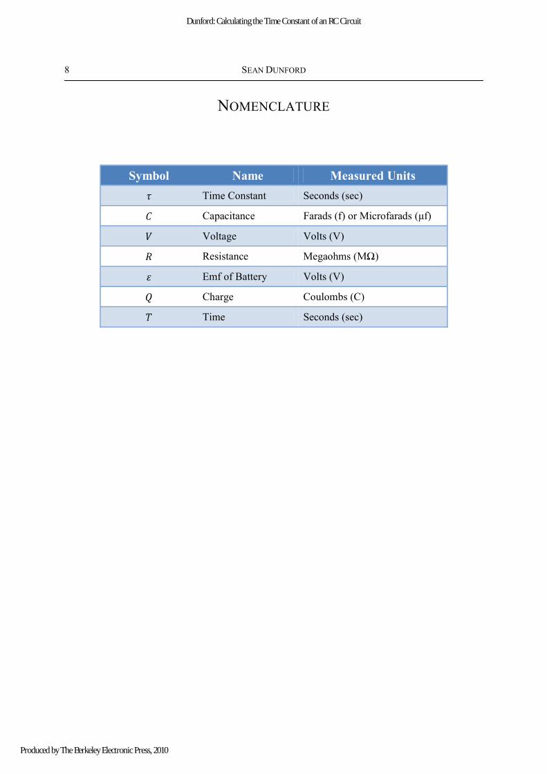
NOMENCLATURE
Symbol Name Measured Units
Time Constant Seconds (sec)
Capacitance Farads (f) or Microfarads ( )
Voltage Volts (V)
Resistance Megaohms ( )
Emf of Battery Volts (V)
Charge Coulombs (C)
Time Seconds (sec)
Dunford: Calculating the Time Constant of an RC Circuit
Produced by The Berkeley Electronic Press, 2010

CALCULATING THE TIME CONSTANT OF AN RC CIRCUIT 9
REFERENCES
Larson, Ron, Robert Hosteteler, and Bruce Edwards. Calculus: Early Transcendental functions.
New York: Houghton Mifflin Company, 2007.
Raymond A., Serway, and John W. Jewett, Jr.. Physics: for Scientist and Engineers. Belmont,
Ca: David Harris, 2005
Koehler , Kenneth R. "Capacitors and RC Circuits". College Physics for Students of Biology and
Chemistry. 04/28/2010 <College Physics for Students of Biology and Chemistry>.
Bill Sheets and Rudolf F. Graf, "RC Timers and Timing Circuits." North Country Radio.
04/27/10 <http://www.northcountryradio.com/PDFs/column008.pdf>.
Undergraduate Journal of Mathematical Modeling: One + Two, Vol. 2, Iss. 2 [2010], Art. 3
https://digitalcommons.usf.edu/ujmm/vol2/iss2/3DOI: http://dx.doi.org/10.5038/2326-3652.2.2.3

10 SEAN DUNFORD
APPENDIX
GRAPH 1.1
TABLE 1.2
Time Voltage
3 28.79984
6 26.39976
7 26.19992
9 22.90024
11 24.10016
13 23.09989
15 22.19985
17 21.2002
18 20.79984
21 18.89992
25 17.9999
26 17.40003
Time Voltage
35 14.39992
40 13.18014
45 11.88995
50 10.73001
55 9.670079
60 8.729915
65 7.869914
70 7.100027
85 5.210027
110 3.109997
135 1.859987
y = 29.83e-0.02x
0
5
10
15
20
25
30
35
0 20 40 60 80 100 120 140
Vol
tage
(vo
lts)
Time (seconds)
Recorded Values
Expon. (Recorded Values)
Graph 1.1 Voltage recorded at the capacitor once the power source was removed.
Dunford: Calculating the Time Constant of an RC Circuit
Produced by The Berkeley Electronic Press, 2010

CALCULATING THE TIME CONSTANT OF AN RC CIRCUIT 11
GRAPH 2.1
TABLE 2.2
Time Voltage
3 3.36037
6 3.273355
7 3.265756
9 3.131147
11 3.182218
13 3.139828
15 3.100086
17 3.054011
18 3.034945
21 2.939158
25 2.890366
26 2.856472
Time Voltage
35 2.667223
40 2.578711
45 2.475694
50 2.373044
55 2.269036
60 2.166756
65 2.063047
70 1.960099
85 1.650585
110 1.134622
135 0.620569
y = -0.020x + 3.395
0
0.5
1
1.5
2
2.5
3
3.5
4
0 20 40 60 80 100 120 140
Vol
tage
(vo
lts)
Time (seconds)
Log[V(t)]
Linear (Log[V(t)])
Graph 2.1 Natural logarithm of the voltages achieved in Graph 1.1 versus time.
Undergraduate Journal of Mathematical Modeling: One + Two, Vol. 2, Iss. 2 [2010], Art. 3
https://digitalcommons.usf.edu/ujmm/vol2/iss2/3DOI: http://dx.doi.org/10.5038/2326-3652.2.2.3