UCS Central – единое средство управления несколькими вычислительными системами Cisco UCS

fineDoc Number: EDCS-<XXXXX>
Last Revision Date: January 27, 2011
Created by: Dave McFarland
Template Ver.
Number:
EDCS-781852 Rev
3
CAE UCS 1.4.1
FC Switch Mode

TABLE OF CONTENTS
......................................................................................................................................................... 1
......................................................................................................................................................... 1
......................................................................................................................................................... 1
1 INTRODUCTION .................................................................................................................. 3
1.1 What Cisco Provides ....................................................................................................... 3 1.2 What the Field Site Must Provide .................................................................................. 3 1.3 Topology Used for this White Paper .............................................................................. 3 1.4 MDS Configuration for TE port .................................................................................... 4
1.5 UCS FC Switch mode and TE port configuration ........................................................ 4 1.6 UCS FC Switch mode and TE port-channel configuration ....................................... 10
1.7 UCS FC module switch mode FC storage port configuration ................................... 18 1.8 UCS FC module switch mode FCoE storage port configuration .............................. 22
1.9 UCS FCoE module zoning and zonesets ...................................................................... 27 1.10 UCS FC module switch mode default-zone enable (permit) .................................. 31 1.11 UCS FC module switch mode Standalone Host HBA configuration ..................... 32

1 Introduction
This White Paper will guide the user through the configuration and verification of FC switch
mode. It will cover creating TE ports to connect to a SAN fabric. Creating SAN port-channels
and utilizing the active zoneset from a connected fabric. This document will also show how to
run standalone with default-zone permit.
This will also cover configuration of direct attach FC and FCoE storage ports.
1.1 What Cisco Provides
Software
UCS 1.4.1 Image
1.2 What the Field Site Must Provide
Hardware Requirements
UCS System with FC modules
FC and FCoE Storage targets
1.3 Topology Used for this White Paper

1.4 MDS Configuration for TE port
Configure MDS ports to connect to UCS ports.
1) Preparing the MDS for switch mode. The links between the MDS and UCS will be E-ports.
We’ll also configure trunking E-ports
interface fc4/11
switchport rate-mode dedicated
switchport mode E
switchport trunk mode auto
no shutdown
interface fc4/12
switchport rate-mode dedicated
switchport mode E
switchport trunk mode auto
no shutdown
1.5 UCS FC Switch mode and TE port configuration
Configure UCS fibre module switch mode and E (ISL) and Trunk E (TE) ports to the upstream
MDS switch

1) Switch mode is required on both 6100’s. Only heterogeneous fc switch mode or NPV mode
is allowed on the same cluster.
Changing to switch mode on one FI will change the setting for both FI’s and cause a reboot of
both 6100s. This is disruptive, both FI’s will reboot more or less simultaneously. All data paths
on both fabrics will be down.

2) After the UCS system reboots, you can check the FC module status.
3) There is no need to configure E-port(s) on the UCS. This is the default configuration.
cae-sj-ca3-A(nxos)# show running-config interface fc 2/1-2
!Command: show running-config interface fc2/1-2
!Time: Wed Oct 20 16:49:39 2010
version 4.2(1)N1(1.4)
interface fc2/1
switchport mode E
no shutdown
interface fc2/2
switchport mode E
no shutdown
4) Set the native VSAN for the E-port(s). As these will be trunk ports capable of carrying
multiple VSANs it is not necessary for both sides to be in the same VSAN. But, some best

practices place both sides in VSAN 1 as it is the default available VSAN on both the MDS and
UCS FC module.
In the GUI do the following:
Or if you want to drive from the CLI:
cae-sj-ca3-A# scope fc-uplink
cae-sj-ca3-A /fc-uplink # enter vsan default 1 1
cae-sj-ca3-A /fc-uplink/vsan # enter member-port a 2 1
cae-sj-ca3-A /fc-uplink/vsan/member-port # exit
cae-sj-ca3-A /fc-uplink/vsan # enter member-port a 2 2
cae-sj-ca3-A /fc-uplink/vsan/member-port # exit
cae-sj-ca3-A /fc-uplink/vsan # set fcoe-vlan 1
cae-sj-ca3-A /fc-uplink/vsan # set id 1
cae-sj-ca3-A /fc-uplink/vsan # exit
cae-sj-ca3-A /fc-uplink # show vsan detail expand
VSAN:
Name: 1
Id: 1
FCoE VLAN: 1
Fabric ID: A
Default Zoning: Disabled
Member Port:
Fabric ID: A
Slot ID: 2
Port ID: 2
Oper State: Up
State Reason:
Oper Speed: 4gbps

Current Task:
Member Port:
Fabric ID: A
Slot ID: 2
Port ID: 1
Oper State: Up
State Reason:
Oper Speed: 4gbps
Current Task:
cae-sj-ca3-A(nxos)# show vsan membership interface fc 2/1-2
fc2/1
vsan:1
allowed list:1-4078,4080-4093
fc2/2
vsan:1
allowed list:1-4078,4080-4093
5) It is best practice to make the native VSAN the same on both end points.
On The MDS side
cae-sj-9506-1# show vsan membership interface fc 4/11-12
fc4/11
vsan:1
allowed list:1-4078,4080-4093
fc4/12
vsan:1
allowed list:1-4078,4080-4093
cae-sj-9506-1# show interface fc 4/11
fc4/11 is trunking
Hardware is Fibre Channel, SFP is short wave laser w/o OFC (SN)
Port WWN is 20:cb:00:0d:ec:24:5b:c0
Peer port WWN is 20:41:00:0d:ec:d3:5d:c0
Admin port mode is E, trunk mode is auto
snmp link state traps are enabled
Port mode is TE
Port vsan is 1
Speed is 4 Gbps
Rate mode is dedicated
Transmit B2B Credit is 16
Receive B2B Credit is 250
Receive data field Size is 2112
Beacon is turned off
Trunk vsans (admin allowed and active) (1,10,50,100,103)

6) The ports should go into the up state on both the MDS and UCS side
7) Show MDS E-port status and VSAN allow list
cae-sj-9506-1(config-if)# show interface fc 1/1-2
fc1/1 is trunking
Hardware is Fibre Channel, SFP is short wave laser w/o OFC (SN)
Port WWN is 20:01:00:0d:ec:24:5b:c0
Peer port WWN is 20:43:00:0d:ec:d3:5d:c0
Admin port mode is E, trunk mode is auto
snmp link state traps are enabled
Port mode is TE
Port vsan is 1
Speed is 4 Gbps
Rate mode is dedicated
Transmit B2B Credit is 16
Receive B2B Credit is 250
Receive data field Size is 2112
Beacon is turned off
Trunk vsans (admin allowed and active) (1,10,50,100,103)
Trunk vsans (up) (1,10,50,100,103)
Trunk vsans (isolated) ()
Trunk vsans (initializing) ()
8) Show UCS E-port status and VSAN allow list
cae-sj-ca3-A(nxos)# show interface fc 2/3
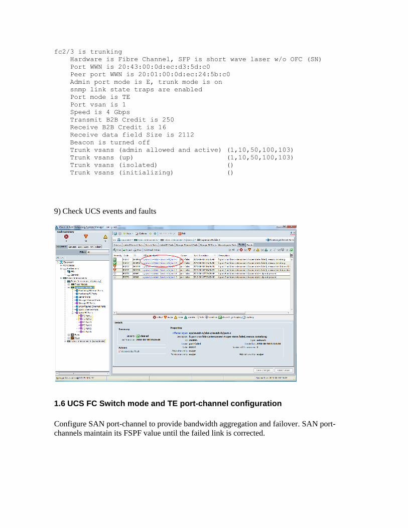
fc2/3 is trunking
Hardware is Fibre Channel, SFP is short wave laser w/o OFC (SN)
Port WWN is 20:43:00:0d:ec:d3:5d:c0
Peer port WWN is 20:01:00:0d:ec:24:5b:c0
Admin port mode is E, trunk mode is on
snmp link state traps are enabled
Port mode is TE
Port vsan is 1
Speed is 4 Gbps
Transmit B2B Credit is 250
Receive B2B Credit is 16
Receive data field Size is 2112
Beacon is turned off
Trunk vsans (admin allowed and active) (1,10,50,100,103)
Trunk vsans (up) (1,10,50,100,103)
Trunk vsans (isolated) ()
Trunk vsans (initializing) ()
9) Check UCS events and faults
1.6 UCS FC Switch mode and TE port-channel configuration
Configure SAN port-channel to provide bandwidth aggregation and failover. SAN port-
channels maintain its FSPF value until the failed link is corrected.

1) Show FC topology to verify connections cae-sj-ca3-A(nxos)# show topo
FC Topology for VSAN 1 :
--------------------------------------------------------------------------------
Interface Peer Domain Peer Interface Peer IP Address
--------------------------------------------------------------------------------
fc2/1 0x62(98) fc4/11 172.25.183.123
fc2/2 0x62(98) fc4/12 172.25.183.123
The connected MDS switch IP is 172.25.183.123. This shows the fc port connections between
the UCS FC module and the MDS line card
2) Configure the MDS port-channel configuration
cae-cae-sj-9506-1# conf t
Enter configuration commands, one per line. End with CNTL/Z.
cae-sj-9506-1(config)# interface port-channel 3
cae-sj-9506-1(config-if)# channel mode active
cae-sj-9506-1(config-if)# switchport mode e
cae-sj-9506-1(config-if)# switchport rate-mode dedicated
cae-sj-9506-1(config-if)# switchport trunk mode auto
cae-sj-9506-1(config-if)# do show run interface port-channel 3
!Command: show running-config interface port-channel 3
!Time: Thu Jan 27 09:44:57 2011
version 4.2(7b)
interface port-channel 3
channel mode active
switchport mode E
switchport rate-mode dedicated
switchport trunk mode auto
3) Configure the MDS TE ports to be members of the port-channel
cae-sj-9506-1# show run interface port-channel 3
!Command: show running-config interface port-channel 3
!Time: Wed Oct 20 17:06:01 2010
version 5.0(1a)
interface port-channel 3
channel mode active
switchport mode E
switchport rate-mode dedicated
switchport trunk mode auto
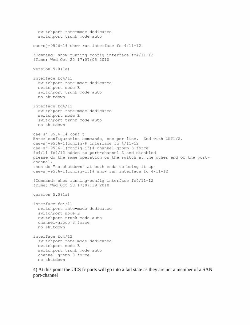
cae-sj-9506-1# show run interface fc 4/11-12
!Command: show running-config interface fc4/11-12
!Time: Wed Oct 20 17:07:05 2010
version 5.0(1a)
interface fc4/11
switchport rate-mode dedicated
switchport mode E
switchport trunk mode auto
no shutdown
interface fc4/12
switchport rate-mode dedicated
switchport mode E
switchport trunk mode auto
no shutdown
cae-sj-9506-1# conf t
Enter configuration commands, one per line. End with CNTL/Z.
cae-sj-9506-1(config)# interface fc 4/11-12
cae-sj-9506-1(config-if)# channel-group 3 force
fc4/11 fc4/12 added to port-channel 3 and disabled
please do the same operation on the switch at the other end of the port-
channel,
then do "no shutdown" at both ends to bring it up
cae-sj-9506-1(config-if)# show run interface fc 4/11-12
!Command: show running-config interface fc4/11-12
!Time: Wed Oct 20 17:07:39 2010
version 5.0(1a)
interface fc4/11
switchport rate-mode dedicated
switchport mode E
switchport trunk mode auto
channel-group 3 force
no shutdown
interface fc4/12
switchport rate-mode dedicated
switchport mode E
switchport trunk mode auto
channel-group 3 force
no shutdown
4) At this point the UCS fc ports will go into a fail state as they are not a member of a SAN
port-channel

cae-sj-ca3-A(nxos)# show interface fc 2/1-2
fc2/1 is down (Isolation due to port-channel mis-configuration)
Hardware is Fibre Channel, SFP is short wave laser w/o OFC (SN)
Port WWN is 20:41:00:0d:ec:d3:5d:c0
Admin port mode is E, trunk mode is on
snmp link state traps are enabled
Port vsan is 1
interface fc2/4
switchport trunk mode on
channel-group 1 force
5) Create the UCS SAN port-channel
no shutdown

6) Enable the port-channel

Or in the UCS CLI:
cae-sj-ca3-A # scope fc-uplink
cae-sj-ca3-A /fc-uplink # scope fabric a
cae-sj-ca3-A /fc-uplink/fabric # enter port-channel 1
cae-sj-ca3-A /fc-uplink/fabric/port-channel* # enable
cae-sj-ca3-A /fc-uplink/fabric/port-channel* # enter member-port 2 1
cae-sj-ca3-A /fc-uplink/fabric/port-channel/member-port* # enable
cae-sj-ca3-A /fc-uplink/fabric/port-channel/member-port* # exit
cae-sj-ca3-A /fc-uplink/fabric/port-channel* # enter member-port 2 2
cae-sj-ca3-A /fc-uplink/fabric/port-channel/member-port* # enable
cae-sj-ca3-A /fc-uplink/fabric/port-channel/member-port* # exit
cae-sj-ca3-A /fc-uplink/fabric/port-channel* # set adminspeed 4gbps
cae-sj-ca3-A /fc-uplink/fabric/port-channel* # exit
cae-sj-ca3-A /fc-uplink/fabric* # enter vsan 1 1 1
cae-sj-ca3-A /fc-uplink/fabric/vsan* # set fcoe-vlan 1
cae-sj-ca3-A /fc-uplink/fabric/vsan* # set id 1
cae-sj-ca3-A /fc-uplink/fabric/vsan* # enter member-port-channel a 1
cae-sj-ca3-A /fc-uplink/fabric/vsan/member-port-channel* # exit
cae-sj-ca3-A /fc-uplink/fabric/vsan* # commit-buffer
cae-sj-ca3-A /fc-uplink/fabric/vsan # exit
cae-sj-ca3-A /fc-uplink/fabric # show
cae-sj-ca3-A /fc-uplink/fabric # show detail expand

Fabric:
Id: A
Uplink Trunking: Enabled
Current Task:
Port Channel:
Channel Id: 1
Name:
Admin State: Enabled
Oper State: Up
Admin Speed: 4 Gbps
Oper Speed (Gbps): 4
Member Port:
Fabric ID: A
Slot Id: 2
Port Id: 1
Membership: Up
Admin State: Enabled
Current Task:
cae-sj-ca3-A(nxos)# show interface san-port-channel 1
san-port-channel 1 is trunking
Hardware is Fibre Channel
Port WWN is 24:01:00:0d:ec:d3:5d:c0
Admin port mode is E, trunk mode is on
snmp link state traps are enabled
Port mode is TE
Port vsan is 1
Speed is 8 Gbps
Trunk vsans (admin allowed and active) (1,10,26,50,66,100-
101,103,123,222,24
0)
Trunk vsans (up) (1,10,50,100,103)
Trunk vsans (isolated) (26,66,101,123,222,240)
Trunk vsans (initializing) ()
5 minute input rate 2312 bits/sec, 289 bytes/sec, 2 frames/sec
5 minute output rate 1440 bits/sec, 180 bytes/sec, 2 frames/sec
2669 frames input, 194760 bytes
0 discards, 0 errors
0 CRC, 0 unknown class
0 too long, 0 too short
2677 frames output, 158316 bytes
0 discards, 0 errors
0 input OLS, 1 LRR, 0 NOS, 0 loop inits
6 output OLS, 10 LRR, 2 NOS, 0 loop inits
Member[1] : fc2/1
Member[2] : fc2/2
Interface last changed at Wed Oct 20 17:16:55 2010
cae-sj-ca3-A(nxos)# show run interface fc 2/1-2

!Command: show running-config interface fc2/1-2
!Time: Wed Oct 20 17:19:41 2010
version 4.2(1)N1(1.4)
interface fc2/1
switchport mode E
channel-group 1 force
no shutdown
interface fc2/2
switchport mode E
channel-group 1 force
no shutdown
cae-sj-ca3-A(nxos)# show run interface san-port-channel 1
!Command: show running-config interface san-port-channel 1
!Time: Wed Oct 20 17:20:12 2010
version 4.2(1)N1(1.4)
interface san-port-channel 1
switchport mode E
no shutdown
:28:10 2010
7) Use the show command to verify the the port-channel configuration on the MDS
cae-sj-9506-1(config-if)# sho interface port-channel 3
port-channel 3 is trunking
Hardware is Fibre Channel
Port WWN is 24:03:00:0d:ec:24:5b:c0
Admin port mode is E, trunk mode is auto
snmp link state traps are enabled
Port mode is TE
Port vsan is 1
Speed is 8 Gbps
Trunk vsans (admin allowed and active) (1,10,50,100,103)
Trunk vsans (up) (1,10,50,100,103)
Trunk vsans (isolated) ()
Trunk vsans (initializing) ()
8) Verify the Fabric Topology
cae-sj-9506-1(config-if)# show topology
FC Topology for VSAN 1 :
--------------------------------------------------------------------------------
Interface Peer Domain Peer Interface Peer IP Address
--------------------------------------------------------------------------------

port-channel 3 0xb2(178) port-channel 3 ::
FC Topology for VSAN 10 :
--------------------------------------------------------------------------------
Interface Peer Domain Peer Interface Peer IP Address
--------------------------------------------------------------------------------
port-channel 3 0x14(20) port-channel 3 ::
FC Topology for VSAN 50 :
--------------------------------------------------------------------------------
Interface Peer Domain Peer Interface Peer IP Address
--------------------------------------------------------------------------------
port-channel 3 0x68(104) port-channel 3 ::
FC Topology for VSAN 100 :
--------------------------------------------------------------------------------
Interface Peer Domain Peer Interface Peer IP Address
--------------------------------------------------------------------------------
port-channel 3 0x8c(140) port-channel 3 ::
FC Topology for VSAN 103 :
--------------------------------------------------------------------------------
Interface Peer Domain Peer Interface Peer IP Address
--------------------------------------------------------------------------------
port-channel 3 0x31(49) port-channel 3 ::
1.7 UCS FC module switch mode FC storage port configuration
1) Use the GUI or CLI in UCS to create a storage VSAN to match the uplink VSAN you
are using for the host HBA


2) Use the CLI to create a storage VSAN
cae-sj-ca3-A# scope fc-storage
cae-sj-ca3-A /fc-storage # scope fabric a
cae-sj-ca3-A /fc-storage/fabric # enter vsan 100 100 100
cae-sj-ca3-A /fc-storage/fabric/vsan* # set fcoe-vlan 100
cae-sj-ca3-A /fc-storage/fabric/vsan* # enter member-port a 2 5
cae-sj-ca3-A /fc-storage/fabric/vsan/member-port* # commit-buffer
cae-sj-ca3-A /fc-storage/fabric/vsan/member-port # exit
cae-sj-ca3-A /fc-storage/fabric/vsan # end
cae-sj-ca3-A /fc-storage # show configuration
scope fc-storage
enter vsan default 1 1
set fcoe-vlan 1
enter member-port b 2 5
exit
exit
scope fabric a
enter interface fc 2 5
enable
set user-label ""
exit
enter vsan 100 100 100
set fcoe-vlan 100
enter member-port a 2 5
exit
exit
exit
scope fabric b
enter interface fc 2 5
enable
set user-label ""
exit
exit
set default-zoning disabled
set fcoe-storage-native-vlan 4048
exit
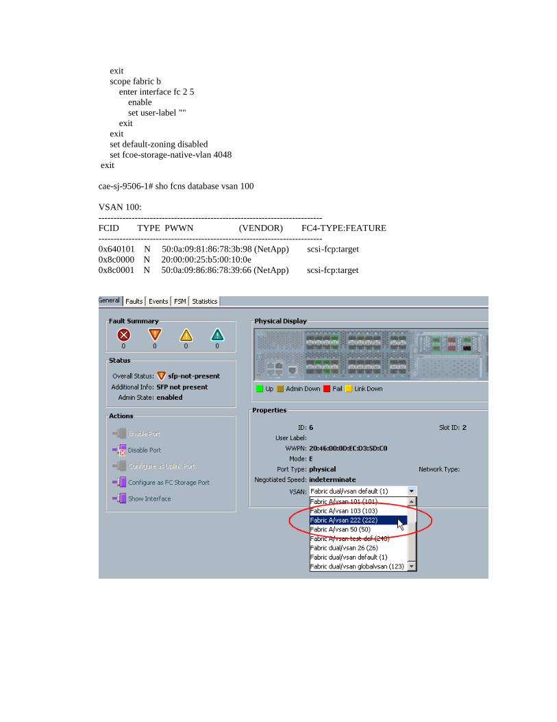
cae-sj-9506-1# sho fcns database vsan 100
VSAN 100:
--------------------------------------------------------------------------
FCID TYPE PWWN (VENDOR) FC4-TYPE:FEATURE
--------------------------------------------------------------------------
0x640101 N 50:0a:09:81:86:78:3b:98 (NetApp) scsi-fcp:target
0x8c0000 N 20:00:00:25:b5:00:10:0e
0x8c0001 N 50:0a:09:86:86:78:39:66 (NetApp) scsi-fcp:target

1.8 UCS FC module switch mode FCoE storage port configuration
Directly attach an FCoE storage port to UCS 10G port
1) Create a VSAN in the Storage Cloud for both the A and B fabric.

Repeat for the B Fabric

In The Equipment Tab, Fabric Interconnect, Unconfigued Ethernet ports, select the port attached to the FCoE storage and configure it as a “Storage Ethernet Port”

By default it will be placed into VSAN 1, move it to your desired VSAN for zoning

Move to VSAN 100
Login to the Fabric Interconnect to verify interface, VSAN, flogi information is as expected
FarNorth-A(nxos)# show interface ethernet 1/20

Ethernet1/20 is up
Hardware: 10000 Ethernet, address: 000d.ecd0.7b5b (bia 000d.ecd0.7b5b)
Description: F: FcoeEstc
MTU 1500 bytes, BW 10000000 Kbit, DLY 10 usec,
reliability 255/255, txload 1/255, rxload 1/255
Encapsulation ARPA
Port mode is trunk
FarNorth-A(nxos)# show interface ethernet 1/20 fcoe
Ethernet1/20 is FCoE UP
vfc1405 is Up
FCID is 0xdc0000
PWWN is 50:0a:09:85:87:d9:6e:b7
MAC addr is 00:c0:dd:11:0d:89
FarNorth-A(nxos)# show interface vfc 1405
vfc1405 is up
Bound interface is Ethernet1/20
FCF priority is 128
Hardware is Virtual Fibre Channel
Port WWN is 25:7c:00:0d:ec:d0:7b:7f
Admin port mode is F, trunk mode is on
snmp link state traps are enabled
Port mode is F, FCID is 0xdc0000
Port vsan is 100
5 minute input rate 64 bits/sec, 8 bytes/s
FarNorth-A(nxos)# show flogi database vsan 100
--------------------------------------------------------------------------------
INTERFACE VSAN FCID PORT NAME NODE NAME
--------------------------------------------------------------------------------
vfc1405 100 0xdc0000 50:0a:09:85:87:d9:6e:b7 50:0a:09:80:87:d9:6e:b7
Total number of flogi = 1.
1.9 UCS FCoE module zoning and zonesets
Create zones and zonesets in FC switch mode
1) With this release there is no method to create zones and zonesets with just the UCS FC
module. You must use a SAN switch that is connected with an E-port.
2) From a connected MDS switch you can view the existing zoneset for each VSAN
TOP# show zoneset active vsan 100
zoneset name ZS_mn_bootcamp_v100 vsan 100
zone name Z_mn_bootcamp_4_v100 vsan 100

* fcid 0x400002 [pwwn 50:0a:09:88:87:d9:6e:b7]
pwwn 20:00:00:25:b5:00:30:08
zone name Z_mn_bootcamp_3_v100 vsan 100
* fcid 0x400002 [pwwn 50:0a:09:88:87:d9:6e:b7]
pwwn 20:00:00:25:b5:00:30:0a
3) From UCS switch you can show the active zoneset that exists from the connected MDS
SAN switch
FarNorth-A(nxos)# show zoneset active vsan 100
zoneset name ZS_mn_bootcamp_v100 vsan 100
zone name Z_mn_bootcamp_4_v100 vsan 100
* fcid 0x400002 [pwwn 50:0a:09:88:87:d9:6e:b7]
pwwn 20:00:00:25:b5:00:30:08
zone name Z_mn_bootcamp_3_v100 vsan 100
* fcid 0x400002 [pwwn 50:0a:09:88:87:d9:6e:b7]
pwwn 20:00:00:25:b5:00:30:0a
4) Show the fcns dabatase information to show the PWWN information from the UCS FC
module (DomainID 0x8c)
FarNorth-A(nxos)# show fcns database vsan 100
VSAN 100:
--------------------------------------------------------------------------
FCID TYPE PWWN (VENDOR) FC4-TYPE:FEATURE
--------------------------------------------------------------------------
0x400002 N 50:0a:09:88:87:d9:6e:b7 (NetApp) scsi-fcp:target
0x40000d N 21:00:00:c0:dd:12:04:fe (Qlogic) scsi-fcp:init
0xdc0000 N 50:0a:09:85:87:d9:6e:b7 (NetApp) scsi-fcp:target
Total number of entries = 3
5) Show the MDS local PWWN information by showing the flogi database
TOP# show fcns database vsan 100
VSAN 100:
--------------------------------------------------------------------------
FCID TYPE PWWN (VENDOR) FC4-TYPE:FEATURE
--------------------------------------------------------------------------
0x400002 N 50:0a:09:88:87:d9:6e:b7 (NetApp) scsi-fcp:target
0x40000d N 21:00:00:c0:dd:12:04:fe (Qlogic) scsi-fcp:init
0xdc0000 N 50:0a:09:85:87:d9:6e:b7 (NetApp) scsi-fcp:target
6) Create a new VSAN 100 zoneset and zones from both the local MDS storage and remote
UCS storage and host initiator
TOP(config)# zoneset name ZS_FCoE_V100 vsan 100
TOP(config-zoneset)# zone name Z_FCoE_V100 vsan 100

TOP(config-zone)# member pwwn 50:0a:09:85:87:d9:6e:b7
TOP(config-zone)# member pwwn 21:00:00:c0:dd:12:04:fe
TOP(config-zoneset)# zoneset name ZS_FCoE_V100 vsan 100
TOP(config-zoneset)# member Z_FCoE_V100
7) On the MDS switch, show the new zoneset configuration
TOP(config-zoneset)# show zoneset name ZS_FCoE_V100 vsan 100
zoneset name ZS_FCoE_V100 vsan 100
zone name Z_FCoE_V100 vsan 100
pwwn 50:0a:09:85:87:d9:6e:b7
pwwn 21:00:00:c0:dd:12:04:fe
8) The zoneset and zone information has not been distributed to the UCS FC module yet. The
old existing VSAN 100 zoneset is still active
FarNorth-A(nxos)# show zoneset name ZS_FCoE_V100 vsan 100
Zoneset not present
FarNorth-A(nxos)# show zoneset active vsan 100
zoneset name ZS_mn_bootcamp_v100 vsan 100
zone name Z_mn_bootcamp_4_v100 vsan 100
* fcid 0x400002 [pwwn 50:0a:09:88:87:d9:6e:b7]
pwwn 20:00:00:25:b5:00:30:08
zone name Z_mn_bootcamp_3_v100 vsan 100
* fcid 0x400002 [pwwn 50:0a:09:88:87:d9:6e:b7]
pwwn 20:00:00:25:b5:00:30:0a
9) On the MDS activate the zoneset in VSAN 100 and check the status
TOP(config-zoneset)# zoneset activate name ZS_FCoE_V100 vsan 100
WARNING: You are trying to activate zoneset ZS_FCoE_V100, which is different
from current active zoneset ZS_mn_bootcamp_v100. Do you want to continue?
(y/n) [n] y
Zoneset activation initiated. check zone status
TOP(config)# show zoneset active vsan 100
zoneset name ZS_FCoE_V100 vsan 100
zone name Z_FCoE_V100 vsan 100
* fcid 0xdc0000 [pwwn 50:0a:09:85:87:d9:6e:b7]
* fcid 0x40000d [pwwn 21:00:00:c0:dd:12:04:fe]
10) Check the VSAN 100 activation status on the UCS fabric interconnect
FarNorth-A(nxos)# show zoneset active vsan 100
zoneset name ZS_FCoE_V100 vsan 100
zone name Z_FCoE_V100 vsan 100
* fcid 0xdc0000 [pwwn 50:0a:09:85:87:d9:6e:b7]
* fcid 0x40000d [pwwn 21:00:00:c0:dd:12:04:fe]

11) Now the zoneset configuration is distributed to the UCS if zoneset distribution is
enabled for the VSAN
This first time I run the command, zoneset distribution is not enabled for the VSAN from the
upstream MDS switch.
FarNorth-A(nxos)# show zoneset name ZS_FCoE_V100 vsan 100
Zoneset not present
I enable distribution for all VSANs and do another zoneset activation
TOP(config)# zoneset distribute full vsan 1-4093
TOP(config)# zoneset activate name ZS_FCoE_V100 vsan 100
Now when I check the Fabric Interconnect, the zoneset configuration information is present.
FarNorth-A(nxos)# show zoneset name ZS_FCoE_V100 vsan 100
zoneset name ZS_FCoE_V100 vsan 100
zone name Z_FCoE_V100 vsan 100
pwwn 50:0a:09:85:87:d9:6e:b7
pwwn 21:00:00:c0:dd:12:04:fe

1.10 UCS FC module switch mode default-zone enable (permit)
You can enable default-zoning, in MDS this is called default-zone permit. This can be used
when there is no attached SAN switch to provide zoning configuration. In this case, all host
hba’s scsi initiators can access all storage targets. Lun masking must be performed to ensure
hosts do not access storage luns for other hosts
cae-sj-ca3-A# scope fc-storage
cae-sj-ca3-A /fc-storage #
cae-sj-ca3-A /fc-storage # scope fabric a
cae-sj-ca3-A /fc-storage/fabric # enter vsan 101 101 101
cae-sj-ca3-A /fc-storage/fabric/vsan # set default-zoning enabled
cae-sj-ca3-A /fc-storage/fabric/vsan # show detail
VSAN:
Name: 101
Id: 101
FCoE VLAN: 101
Fabric ID: A
Default Zoning: Enabled
cae-sj-ca3-A(nxos)# show run | include default-zone
zone default-zone permit vsan 100-101

1.11 UCS FC module switch mode Standalone Host HBA configuration
1) In an environment where there is no Northbound SAN connectivity and no uplinks are
configured, the host service profile HBA will need to be assigned to the same VSAN as its
direct attach storage VAN