CADMAN 6003 3-Point Hitch Hose Caddy · CADMAN 6003 3-Point Hitch Hose Caddy OPERATOR’S PARTS and...
26
CADMAN 6003 3-Point Hitch Hose Caddy OPERATOR’S PARTS and MAINTENANCE MANUAL 2006 EDITION TR-MAN-6003
Transcript of CADMAN 6003 3-Point Hitch Hose Caddy · CADMAN 6003 3-Point Hitch Hose Caddy OPERATOR’S PARTS and...

CADMAN 6003 3-Point Hitch Hose Caddy
OPERATOR’S PARTS and MAINTENANCE MANUAL 2006 EDITION
TR-MAN-6003


TR-MAN-60033-POINT HITCH HOSE CADDY
Creation Revision date: 10MAR06 date:
by: Ivon LeBlanc by:
Page 1 of 24
Table of Contents Table of Contents ..................................................................................................... 1
3-Point Hitch Hose Caddy......................................................................................... 3
Warranty Policy......................................................................................................... 4
When Applying Liquid Manure .................................................................................. 5
Safety Precautions.................................................................................................... 6
Important Note .......................................................................................................... 7
Safety Decals............................................................................................................ 8
Unloading Your Hose Caddy .................................................................................... 9
Loading Your Hose Caddy...................................................................................... 11
Parts Section .......................................................................................................... 13
Required Maintenance............................................................................................ 22
Useful Information................................................................................................... 24

TR-MAN-6003 3-POINT HITCH HOSE CADDY
Page 2 of 24

TR-MAN-6003 3-POINT HITCH HOSE CADDY
Page 3 of 24
3-Point Hitch Hose Caddy We would like to thank you for purchasing your new Cadman 3-Point Hitch Hose
Caddy. You have purchased a product of superior quality that will serve your needs for a long time provided you follow this manual and safety procedures.
Figure 1 - Cadman 3-Point Hitch Hose Caddy img-00168.png
BEFORE operating your new Cadman 3-Point Hitch Hose Caddy, inspect the machine for any damage or parts which may have come loose during shipping. REPORT ANY DAMAGE TO CADMAN POWER EQUIPMENT LIMITED OR YOUR LOCAL DEALER IMMEDIATELY!

TR-MAN-6003 3-POINT HITCH HOSE CADDY
Page 4 of 24
Warranty Policy CADMAN POWER EQUIPMENT LIMITED warrants that each machine it
manufactures shall be free from defects in materials and workmanship. The terms of this warranty are as follows:
• All components manufactured by CADMAN POWER EQUIPMENT LIMITED shall be warranted for a period of one (1) year from the date of delivery, except the frame and hose drum structures which shall be warranted for a period of three (3) years.
• CADMAN POWER EQUIPMENT LIMITED makes no warranty whatsoever in regard to tires, engines, and other trade accessories used on its equipment. The customer shall rely solely on the warranties offered (if any) by the respective manufacturer of these trade accessories.
The sole obligation to CADMAN POWER EQUIPMENT LIMITED under this warranty is limited to the repair or replacement of any part it manufactured, which, in the judgment of CADMAN POWER EQUIPMENT LIMITED, failed under normal and proper use and maintenance due to defective materials or workmanship. All freight charges incurred shall be the sole responsibility of the customer.
CADMAN POWER EQUIPMENT LIMITED and its dealers (who are neither authorized nor qualified to undertake any obligations on behalf of CADMAN POWER EQUIPMENT LIMITED) DO NOT, under any circumstances, accept any responsibility for any losses or costs incurred due to parts failure and/or delays during the parts replacement process.
This warranty will be considered void if any alterations or modifications have been made to the machine without the express written consent of CADMAN POWER EQUIPMENT LIMITED outlining the nature and the extent of such modifications.
CADMAN POWER EQUIPMENT LIMITED, whose policy is one of continuous improvement, reserves the right to change specifications and designs without notice or incurring obligation.
The warranties expressed herein are non-transferable and replace any other warranties, either written or verbal, which may have been given or implied.

TR-MAN-6003 3-POINT HITCH HOSE CADDY
Page 5 of 24
When Applying Liquid Manure Environmental concerns seem to be driving legislative agendas in many agricultural
areas across the continent. Current and pending laws in many agricultural regions of North America are changing the ways in which the agricultural community is expected to manage their liquid animal waste products.
The changes in legislation typically target two main issues; run-off prevention during and after application and soil nutrient loading.
Run-off seems to be the largest concern with nutrient application. Run-off may result from several different factors, most of which are controllable. These factors include; exceeding the soil intake rate; nutrient application on steep grades; high application amounts; leaking mainline fittings and seals; sudden rainfall during or immediately after application; ground frost; etc. Constant watch must be kept and immediate action taken when necessary to prevent run-off from occurring.
Soil nutrient loading depends on many variables. Some of these variables (but certainly not all) are soil type, type of crop being grown in the irrigated area, application timing, nutrient value of the material being applied (nutrient value should be assessed at the time of application as it can change throughout the year), etc.
Soil type will determine the intake rate at which liquid may be applied. Cultivation of the field just prior to application can improve the intake rate of some soils.
Great potential benefit lies in using the nutritional value of the nutrient being applied to replace some or all of the traditional chemical fertilizer used. Application timing and amount are important considerations. Soil analysis taken prior to planting and during the growth periods of the crop will help determine if there is room for further application amounts to be added prior to crop maturity. A total management plan should include provisions to end the crop season without surplus nutrients left as residual. These excess nutrients typically end up in the ground water supply. Local colleges, universities and agricultural extension services are usually a good source of information. They can usually help you determine an application program that prevents soil nutrient overload due to excess application.
Cadman Power Equipment Limited cannot possibly provide up-to-date recommendations with regard to the legal obligations you must deal with in your particular area. However, as a manufacturer of equipment used in nutrient application (liquid manure, milk house run-off, etc.), we feel it necessary to make you aware that the municipal, regional and state governing bodies in your area may have recently enacted new legislation or revised existing legislation with regard to nutrient handling practices and procedures.
It is your responsibility to make yourself aware of and abide by the current legislation in your area. Please take the time to contact your local agricultural representative to obtain the latest information regarding legal handling and application of nutrient.

TR-MAN-6003 3-POINT HITCH HOSE CADDY
Page 6 of 24
Safety Precautions Please take the time to read and understand this manual so that unnecessary
errors and risks are avoided. If you have any questions or concerns, please contact Cadman Power Equipment Ltd. or your local dealer/distributor.
• DO NOT move or operate this machine until you have read and understand these instructions in this manual.
• NEVER allow untrained persons to operate this machine.
• DO NOT attempt to service this machine while it is in operation.
• MAKE CERTAIN all mechanical and hydraulic tension has been released before attempting any service on the machine.
• CHECK all fasteners (nuts and bolts) regularly for tightness.
• PERFORM REQUIRED MAINTENANCE as prescribed or as necessary to keep this machine in safe operating condition.
• KEEP ALL SPECTATORS at a safe distance.
• STAY CLEAR of high pressure supply lines, especially when first pressurizing the system.
• DO NOT remove or alter any shielding on this machine.
• KEEP CLEAR of all moving parts.
• REGULAR INSPECTION of your pipe couplings, tubing and gaskets should be a part of your regular set-up routine. Any defective parts MUST be replaced or repaired before the machine is put into service.
This symbol, the safety-alert symbol, indicates a hazard. When you come across this safety-alert symbol in this manual, make certain you fully understand and abide by the given instructions or warnings.
OPERATOR NOTESafety is just a word until put into practice.
Safety must be the first thing on your mind when operating any piece of machinery.
Failure to follow all safety instructions can result in serious injury or death to you or any spectators.
Remember…
SAFETY FIRST!

TR-MAN-6003 3-POINT HITCH HOSE CADDY
Page 7 of 24
Important Note Things to keep in mind while using the Cadman 3-Point Hitch Hose Caddy are:
• This Hose Caddy is capable of holding the following number soft hoses:
Hose Size Quantity ∅ 6 in. X 660 ft 3 ∅ 8 in. X 660 ft 2 ½
• The hose is a high volume “Receiver Tank” containing a large amount of fluid. Be sure to allow enough spreading area to properly distribute the hose contents.
Ø 6” hose contains approximately 1 ½ US Gallons per foot Ø 8” hose contains approximately 2 ⅔ US Gallons per foot
660 1320 1980 2640 3300 3960 4620 5280 5940 6600 FeetØ 6" 969 1939 2908 3877 4847 5816 6785 7755 8724 9693 US GalØ 8" 1723 3447 5170 6893 8616 10340 12063 13786 15509 17233 US Gal
• Hose couplings should be maintained and in good working order. Check for broken
or damaged couplings and replace where necessary.
• Be sure that there is no contained pressure in the lines prior to uncoupling the hose connections. Serious injury or death to you or your spectators could result.

TR-MAN-6003 3-POINT HITCH HOSE CADDY
Page 8 of 24
Safety Decals The safety decals on this machine are intended to warn the operator of potential
hazards. It is important that these decals are properly maintained.
• keep all safety decals legible (remove dirt or debris)
• replace any damaged or illegible decals
• replace any missing decals
• if applicable, include the current safety decal specified by Cadman Power Equipment Limited on any components installed during repair
Figure 2 - Replace Decals img-00131.png
To obtain the required replacement safety decals contact Cadman Power Equipment Limited. Re-install all decals in the proper location on the machine. For part numbers and locations please refer to the Decal Assembly drawing of this manual on page 20.

TR-MAN-6003 3-POINT HITCH HOSE CADDY
Page 9 of 24
Unloading Your Hose Caddy Complete the following instructions to unload your Hose Caddy…
Step 1 Connect your tractors 3-Point Hitch to the Hose Caddy. You can mount this unit on
most Category 2, 3, or 3N three-point hitch system and for more convenience a Quick Hitch system. Connect hydraulic lines to the tractor.
Figure 3 - Connect to caddy with 3-Point Hitch (Quick Hitch System shown) img-00169.png
Step 2 Make sure to disengage the tractor hydraulics. Transport the hose caddy to the
required site.

TR-MAN-6003 3-POINT HITCH HOSE CADDY
Page 10 of 24
Step 3 Once on site, engage the tractor hydraulics so that the drum
rotates away from the rear of the tractor. This will allow the soft hose to unreel.
Step 4 As you unreel the soft hose drive the tractor (at a low rate of
speed) along the required hose path.
Figure 4 - Unreel Hose Slowly img-00170.wmf
Step 5 When the soft hose is nearing the last wrap stop the tractor and disengage the
hydraulics. Slowly rotate the drum so that the hose end fitting can be easily removed.
Step 6 To prevent damage to the hose fitting, remove the hose end manually from the Hose
Caddy.
OPERATOR NOTEWhere field conditions permit, always attempt to pull the hose either up or down sloping terrain instead of operating across a side hill.
SAFETY FIRST!

TR-MAN-6003 3-POINT HITCH HOSE CADDY
Page 11 of 24
Loading Your Hose Caddy Prior to loading the Hose Caddy Cadman Power Equipment Limited recommends that you clean the hoses with a proper clean-out procedure (i.e. clean-out ball launcher or water flushing).
Complete the following instructions to load your Hose Caddy…
Step 1 Position the Hose Caddy relatively straight to the hose end. Disconnect a section of
the soft hose by uncoupling the clamp.
Never pull more than two (2) hoses at one time. Extensive damage to your Hose Caddy will result.
Step 2 Position the Hose Caddy with the tractor so that one end of the soft hose can be
inserted into the opening in the hose drum. (see Figure 5)
Figure 5 - Insert Hose into Reel Opening img-00171.png
Step 3 With one end of the soft hose inserted into the drum, engage the tractor hydraulics
so that the drum rotates towards the tractor.
Step 4 Guide the hose so that it is evenly distributed over the entire reel.
Step 5 When the first hose has been retrieved, return to Step 1 for the remaining hoses.

TR-MAN-6003 3-POINT HITCH HOSE CADDY
Page 12 of 24

TR-MAN-6003 3-POINT HITCH HOSE CADDY
Page 13 of 24
Parts Section
From Serial Number: 0710603HC63 - 6003
Frame Assembly ∗ ............................................................................................ 14
Drive Assembly................................................................................................. 16
Decals ∗ ............................................................................................................. 20
∗
Up to Serial Number: 0700507HC63 - 6003
Drive Assembly................................................................................................. 18
∗ All assemblies marked with an asterisk apply to all model serial numbers.

TR-MAN-6003 3-POINT HITCH HOSE CADDY
Page 14 of 24
Frame Assembly ∗ 6003(All Models)

TR-MAN-6003 3-POINT HITCH HOSE CADDY
Page 15 of 24
Frame Assembly ∗ 6003(All Models)
Item Description Part Number Qty 1 BEARING RETAINING PLATE 05-622 2 2 UPPER HITCH PIN 13-397 1 3 LOWER HITCH PIN 13-405 2 4 DRUM DRIVE LUG 15-040-B 12 5 FRAME, HOSE CADDY 3PT HITCH 19-400 1 6 DRUM WELDMENT 19-500 1 7 CHAIN GUARD WELDMENT 19-601 1 8 TOOL BOX DOOR 19-602 2 9 BRASS HINGE PIN 19-603 2
10 LABEL, GREASE POINT 40-041-A 1 11 LABEL, ENTANGLEMENT 40-051-A 1 12 RUBBER LATCH KIT 40-217 2 13 CADMAN SERIAL NUMBER TAG 40-238 1 14 LABEL, ROTATING DRUM 40-287-A 3 15 3 POINT HOSE CADDY PANEL DECAL 40-530-6003 2 16 AMBER REFLECTIVE DECAL 40-598 4 17 RED REFLECTIVE DECAL 40-599 4 18 2 1/2 IN. PILLOW BLOCK BEARING 40-602 2 19 CADMAN 3 PT HOSE DRUM DECAL 40-706 4 20 LABEL, LIFT POINT 40-933 2 21 LABEL, TIE DOWN POINT 40-947 4 22 5/8-11 X 1.25 STAINLESS STEEL BOLT 88-BLT-06311X125 2 23 3/4-10 X 2.00 STAINLESS STEEL BOLT 88-BLT-07510X200 4 24 1/2-13 STAINLESS STEEL JAM NUT 88-NUT-JAM050-13 12 25 1/2 STAINLESS STEEL LOCK WASHER 88-WSR-LOC050 12 26 5/8 STAINLESS STEEL LOCK WASHER 88-WSR-LOC063 2 27 3/4 STAINLESS STEEL SAE FLAT WASHER 88-WSR-SAE075 4 28 5/16-18X3/4 LG. FLANGE HEAD BOLT 90-BLT-F03118X075 2 29 STD. LYNCH PIN 90-PIN-LYNCH 5 30 3/16 X 3/8 LG. RIVET 90-RIV-019X038 10 31 1/4 X 1.00 TEK SCREW 90-SCR-TEK025X100 2 32 1/4 NYLON FLAT WASHER 90-WSR-FLT025NYLON 2

TR-MAN-6003 3-POINT HITCH HOSE CADDY
Page 16 of 24
Drive Assembly 6003(From 0710603HC63)
22
19
4
27
6
13
23
5
5
39
1415 17
1
3 25
7
21
26
9 27
16 22182410
8
11
20
23
2
12 26
DETAIL A

TR-MAN-6003 3-POINT HITCH HOSE CADDY
Page 17 of 24
Drive Assembly 6003(From 0710603HC63)
Item Description Part Number Qty 1 SPROCKET RETAINING PLATE 01-314-B 1 2 SPRING ADJUSTING ROD 06-635-B 1 3 QD BUSHING 1 1/4 X 5/16 IN. KEYWAY 10-BUS-QD125 1 4 #80 RIVETED ROLLER CHAIN/LINK 10-CHN-80-1RIV 1 5 #80 CONNECTING LINK 10-LNK-80CONN 1 6 #80-12 X 3/4 IDLER SPROCKET 10-SPT-80-12IDLER 1 7 80 QD 15 SPROCKET 10-SPT-80B15QD 1 8 IDLER ARM 16-610-A 1 9 IDLER ARM BUSHING, 1 1/4 IN X 3 LG. 16-611-A 1
10 ADAPTER - #10 JIC-M C #10 SAE-M 25-WHD-5315X10 2 11 1/8 NPT GREASE FITTING 40-001 1 12 1 3/4 X 5 EXT. SPRING (IDLER) 40-056 1 13 3/4 X 3/4 IN. LG. SPACER 40-118 1 14 8.50 IN H.D. CABLE TIE BLACK UV 40-470 4 15 HYDRAULIC COUPLER TIP 40-563 2 16 HYDRAULIC MOTOR - 510 RPM @ 3440 40-609 1 17 3/4 IN. X 132 IN. LG. HYDRAULIC HOSE 40-HHZ-0160 2 18 DOUBLE CROSS PORT RELIEF VALVE 40-HYD-CPR 1 19 3/8-16 X 2.00 STAINLESS STEEL BOLT 88-BLT-03816X200 1 20 1/2-13 X 2.00 STAINLESS STEEL BOLT 88-BLT-05013X200 4 21 3/4-10 X 5.00 STAINLESS STEEL BOLT 88-BLT-07510X500 1 22 1/2-13 STAINLESS STEEL LOCK NUT 88-NUT-LOC050-13 5 23 3/4-10 STAINLESS STEEL LOCKNUT 88-NUT-LOC075-10 2 24 3/8-16 X 1.50 SHCS GR.8 88-SCR-SH03816X150 2 25 3/8 STAINLESS STEEL SAE WASHER 88-WSR-SAE038 1 26 1/2 STAINLESS STEEL SAE FLAT WASHER 88-WSR-SAE050 5 27 3/4 STAINLESS STEEL SAE FLAT WASHER 88-WSR-SAE075 6

TR-MAN-6003 3-POINT HITCH HOSE CADDY
Page 18 of 24
Drive Assembly 6003(0700507HC63 or earlier)
D
D
4
5
23
11
21
224
27
31
18
31
12
27
19
289
6
13
15
14
288
1 3032
25
726
32
3
11
16 17
2922
16 20
C
C A
A
B
B
A

TR-MAN-6003 3-POINT HITCH HOSE CADDY
Page 19 of 24
Drive Assembly 6003(0700507HC63 or earlier)
Item Description Part Number Qty 1 SPROCKET RETAINING PLATE 01-314-B 1 2 SPRING ADJUSTING ROD 06-635-B 1 3 QD BUSHING 1 1/4 X 5/16 IN. KEYWAY 10-BUS-QD125 1 4 #80 RIVETED ROLLER CHAIN/LINK 10-CHN-80-1RIV 1 5 #80 CONNECTING LINK 10-LNK-80CONN 1 6 #80-12 X 3/4 IDLER SPROCKET 10-SPT-80-12IDLER 1 7 80 QD 15 SPROCKET 10-SPT-80B15QD 1 8 IDLER ARM 16-610-A 1 9 IDLER ARM BUSHING, 1 1/4 IN X 3 LG. 16-611-A 1
10 DRUM WELDMENT 19-500 1 11 ADAPTER, #12 JIC-M X #12 NPT-M 25-WHD-5205X12 4 12 ADAPTER - #10 JIC-M C #10 SAE-M 25-WHD-5315X10 2 13 1/8 NPT GREASE FITTING 40-001 1 14 1 3/4 X 5 EXT. SPRING (IDLER) 40-056 1 15 3/4 X 3/4 IN. LG. SPACER 40-118 1 16 8.50 IN H.D. CABLE TIE BLACK UV 40-470 4 17 HYDRAULIC COUPLER TIP 40-563 2 18 HYDRAULIC MOTOR - 510 RPM @ 3440 40-609 1 19 3/4 IN. X 62 IN. LG. HYDRAULIC HOSE 40-723 2 20 3/4 IN. X 60 IN. LG. HYDRAULIC HOSE 40-724 2 21 CUSHION RELIEF VALVE 40-HYD-DWV752000 1 22 5/16-18 X 3.50 STAINLESS STEEL BOLT 88-BLT-03118X350 2 23 3/8-16 X 2.00 STAINLESS STEEL BOLT 88-BLT-03816X200 1 24 1/2-13 X 2.00 STAINLESS STEEL BOLT 88-BLT-05013X200 4 25 3/4-10 X 2.75 STAINLESS STEEL BOLT 88-BLT-07510X275 1 26 3/4-10 X 5.00 STAINLESS STEEL BOLT 88-BLT-07510X500 1 27 1/2-13 STAINLESS STEEL LOCKNUT 88-NUT-LOC050-13 5 28 3/4-10 STAINLESS STEEL LOCKNUT 88-NUT-LOC075-10 2 29 5/16 STAINLESS STEEL LOCK WASHER 88-WSR-LOC031 2 30 3/8 STAINLESS STEEL SAE WASHER 88-WSR-SAE038 1 31 1/2 STAINLESS STEEL SAE FLAT WASHER 88-WSR-SAE050 5 32 3/4 STAINLESS STEEL SAE FLAT WASHER 88-WSR-SAE075 6

TR-MAN-6003 3-POINT HITCH HOSE CADDY
Page 20 of 24
Decals ∗ 6003(All Models)
12
910
3
467
58
10
2
110
6
6
74
8
59
3
TR-MAN-6003 3-POINT HITCH HOSE CADDY
Page 21 of 24
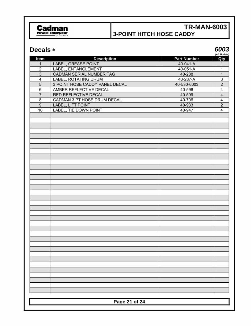
Decals ∗ 6003(All Models)
Item Description Part Number Qty 1 LABEL, GREASE POINT 40-041-A 1 2 LABEL, ENTANGLEMENT 40-051-A 1 3 CADMAN SERIAL NUMBER TAG 40-238 1 4 LABEL, ROTATING DRUM 40-287-A 3 5 3 POINT HOSE CADDY PANEL DECAL 40-530-6003 2 6 AMBER REFLECTIVE DECAL 40-598 4 7 RED REFLECTIVE DECAL 40-599 4 8 CADMAN 3 PT HOSE DRUM DECAL 40-706 4 9 LABEL, LIFT POINT 40-933 2
10 LABEL, TIE DOWN POINT 40-947 4

TR-MAN-6003 3-POINT HITCH HOSE CADDY
Page 22 of 24
Required Maintenance Prevention of mechanical failure is the goal of any good maintenance schedule. The
secret to preventing unwanted down time is to adhere to a maintenance schedule suited to the way you use the equipment. Your maintenance schedule should include the following minimum requirements:
Maintenance must be done ONLY when the machine is on level ground and disconnected from the tractors hydraulics and 3-point hitch.
Each Use Maintenance Item Figure Procedure
Visually inspect equipment N / A Walk around the unit and inspect for loose, missing or damaged items. Check the condition of the drive chain and connecting link. Replace missing or damaged items and tighten loosened items.
Adjust, if necessary, the alignment and tension of the
drive chain
Figure 6 The drive chain (around the drum) is properly tensioned when it has no visible slack and is seating properly onto the drive pegs when the drum rotates. Adjustments are made by turning the locknut (3/4” wrench) on the spring adjustment rod.
Lubricate all grease fittings Figure 7 Using a grease gun, lubricate each grease fitting with an appropriate amount of acceptable grease. (See Lubricants)
Table 1 - Required Maintenance - Each Use
Figure 6 - Chain Tension Adjuster img-00165.png

TR-MAN-6003 3-POINT HITCH HOSE CADDY
Page 23 of 24
Figure 7 - Grease Points img-00167.png
Before Storing Maintenance Item Figure Procedure
Visually inspect equipment N / A Walk around the unit and inspect for loose, missing or damaged items. Replace missing or damaged items and tighten loosened items.
Clean unit N / A Wash down the unit’s exterior. Washing thoroughly with reduce corrosion damage.
Lubricate drive chain N / A Brush the drive chain with acceptable grease. (see “Lubricants”)
Table 2 – Required Maintenance - Before Storing
Lubricants Grease: Any good grade multi-purpose, waterproof grease is compatible
with the greasing requirements of your Cadman 3-Point Hitch Hose Caddy.
NOTE: Proper storage of the Cadman 3-point Hitch Hose Caddy will greatly prolong the operational life of the unit.
TR-MAN-6003 3-POINT HITCH HOSE CADDY
Page 24 of 24
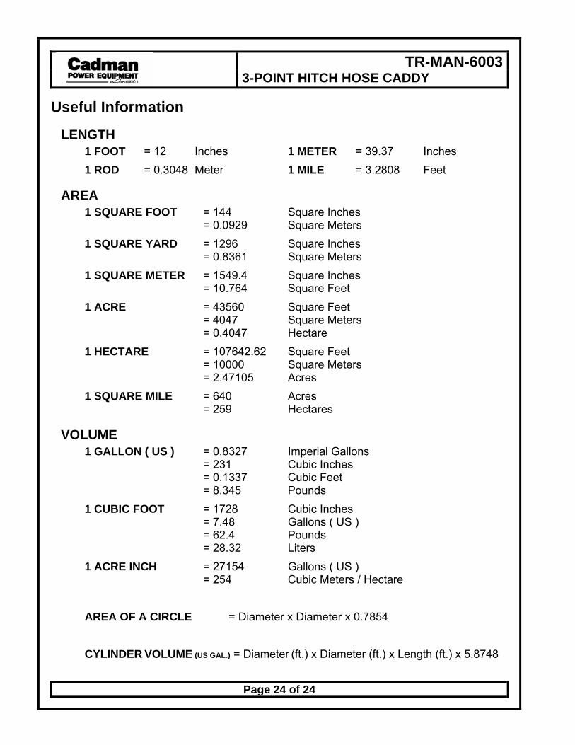
Useful Information
LENGTH 1 FOOT = 12 Inches 1 METER = 39.37 Inches 1 ROD = 0.3048 Meter 1 MILE = 3.2808 Feet
AREA 1 SQUARE FOOT = 144 Square Inches = 0.0929 Square Meters 1 SQUARE YARD = 1296 Square Inches = 0.8361 Square Meters 1 SQUARE METER = 1549.4 Square Inches = 10.764 Square Feet 1 ACRE = 43560 Square Feet = 4047 Square Meters = 0.4047 Hectare 1 HECTARE = 107642.62 Square Feet = 10000 Square Meters = 2.47105 Acres 1 SQUARE MILE = 640 Acres = 259 Hectares
VOLUME 1 GALLON ( US ) = 0.8327 Imperial Gallons = 231 Cubic Inches = 0.1337 Cubic Feet = 8.345 Pounds 1 CUBIC FOOT = 1728 Cubic Inches = 7.48 Gallons ( US ) = 62.4 Pounds = 28.32 Liters 1 ACRE INCH = 27154 Gallons ( US ) = 254 Cubic Meters / Hectare AREA OF A CIRCLE = Diameter x Diameter x 0.7854 CYLINDER VOLUME (US GAL.) = Diameter (ft.) x Diameter (ft.) x Length (ft.) x 5.8748